

Page 1

Page 2

Version 1.0
Published May 2019
Copyright©2019 ASRock INC. All rights reser ved.
Copyright Notice:
No part of this documentation may be reproduced, transcribed, transmitted, or
translated in any language, in any form or by any means, except duplication of
documentation by the purchaser for backup purpose, without written consent of
ASRock Inc.
Products and corporate names appearing in this documentation may or may not
be registered trademarks or copyrights of their respective companies, and are used
only for identication or explanation and to the owners’ benet, without intent to
infringe.
Disclaimer:
Specications and information contained in this documentation are furnished for
informational use only and subject to change without notice, and should not be
constructed as a commitment by ASRock. ASRock assumes no responsibility for
any errors or omissions that may appear in this documentation.
With respect to the contents of this documentation, ASRock does not provide
warranty of any kind, either expressed or implied, including but not limited to
the implied warranties or conditions of merchantability or tness for a particular
purpose.
In no event shall ASRock, its directors, ocers, employees, or agents be liable for
any indirect, special, incidental, or consequential damages (including damages for
loss of prots, loss of business, loss of data, interruption of business and the like),
even if ASRock has been advised of the possibility of such damages arising from any
defect or error in the documentation or product.
is device complies with Part 15 of the FCC Rules. Operation is subject to the following
two conditions:
(1) this device may not cause harmful interference, and
(2) this device must accept any interference received, including interference that
may cause undesired operation.
CALIFORNIA, USA ONLY
e Lithium battery adopted on this motherboard contains Perchlorate, a toxic substance
controlled in Perchlorate Best Management Practices (BMP) regulations passed by the
California Legislature. When you discard the Lithium battery in California, USA, please
follow the related regulations in advance.
“Perchlorate Material-special handling may apply, see ww w.dtsc.ca.gov/hazardouswaste/
perchlorate”
ASRock Website: http://www.asrock.com
Page 3

AUSTRALIA ONLY
Our goods come with guarantees that cannot be excluded under the Australian
Consumer Law. You are entitled to a replacement or refund for a major failure and
compensation for any other reasonably foreseeable loss or damage caused by our
goods. You are also entitled to have the goods repaired or replaced if the goods fail
to be of acceptable quality and the failure does not amount to a major failure. If
you require assistance please call ASRock Tel : +886-2-28965588 ext.123 (Standard
International call charges apply)
e terms HDMI® and HDMI High-Denition Multimedia Interface, and the
HDMI logo are trademarks or registered trademarks of HDMI Licensing LLC in the
United States and other countries.
Page 4
CE Warning
is device complies with directive 2014/53/EU issued by the Commision of the European
Community.
is equipment complies with EU radiation exposure limits set forth for an uncontrolled
environment.
is equipment should be installed and operated with minimum distance 20cm between
the radiator & your body.
Operations in the 5.15-5.35GHz band are restricted to indoor usage only.
Radio transmit power per transceiver ty pe
Function Frequency Maximum Output Power (EIRP)
2400-2483.5 MHz 18.5 + / -1.5 dbm
5150-5250 MHz 21.5 + / -1.5 dbm
WiFi
Bluetooth 2400-2483.5 MHz 8.5 + / -1.5 dbm
5250-5350 MHz
5470-5725 MHz
18.5 + / -1.5 dbm (no TPC)
21.5 + / -1.5 dbm (TPC)
25.5 + / -1.5 dbm (no TPC)
28.5 + / -1.5 dbm (TPC)
Page 5

Contents
Chapter 1 Introduction 1
1.1 Package Contents 1
1.2 Specications 2
1.3 Motherboard Layout 8
1.4 I/O Panel 10
Chapter 2 Installation 14
2.1 Installing the CPU 15
2.2 Installing the CPU Fan and Heatsink 17
2.3 Installing Memory Modules (DIMM) 26
2.4 Expansion Slots (PCI Express Slots) 29
2.5 Jumpers Setup 30
2.6 Onboard Headers and Connectors 31
2.7 Smart Switches 37
2.8 Dr. Debug 39
2.9 SLITM and Quad SLITM Operation Guide 45
2.9.1 Installing Two SLITM-Ready Graphics Cards 45
2.9.2 Driver Installation and Setup 47
2.10 CrossFireXTM , 3-Way CrossFireXTM and Quad CrossFireXTM
Operation Guide 48
2.10.1 Installing Two CrossFireXTM-Ready Graphics Cards 48
Page 6

2.10.2 Installing Three CrossFireXTM-Ready Graphics Cards 50
2.11 M.2_SSD (NGFF) Module Installation Guide (M2_1) 52
2.12 M.2_SSD (NGFF) Module Installation Guide (M2_2) 55
2.13 M.2_SSD (NGFF) Module Installation Guide (M2_3) 58
Chapter 3 Software and Utilities Operation 61
3.1 Installing Drivers 61
3.2.1 Installing Phantom Gaming Tuning 62
3.2.2 Using Phantom Gaming Tuning 62
3.3 ASRock Live Update & APP Shop 65
3.3.1 UI Overview 65
3.3.2 Apps 66
3.3.3 BIOS & Drivers 69
3.3.4 Setting 70
3.4 Creative SoundBlaster Cinema5 71
3.5 ASRock Polychrome SYNC 72
Chapter 4 UEFI SETUP UTILITY 75
4.1 Introduction 75
4.1.1 UEFI Menu Bar 75
4.1.2 Navigation Keys 76
4.2 Main Screen 77
4.3 OC Tweaker Screen 78
4.4 Advanced Screen 82
4.4.1 CPU Conguration 83
4.4.2 Onboard Devices Conguration 84
Page 7

4.4.3 Storage Conguration 86
4.4.4 ACPI Conguration 87
4.4.5 Super IO Conguration 88
4.4.6 Trusted Computing 89
4.4.7 AMD CBS 90
4.4.8 AMD PBS 91
4.4.9 AMD Overclocking 92
4.5 Tools 93
4.6 Hardware Health Event Monitoring Screen 94
4.7 Security Screen 97
4.8 Boot Screen 98
4.9 Exit Screen 100
Page 8

X570 Phantom Gaming X
Chapter 1 Introduction
ank you for purchasing ASRock X570 Phantom Gaming X motherboard, a
reliable motherboard produced under ASRock’s consistently stringent quality
control. It delivers excellent performance with robust design conforming to
ASRock’s commitment to quality and endurance.
In this documentation, Chapter 1 and 2 contains the introduction of the
motherboard and step-by-step installation guides. Chapter 3 contains the operation
guide of the soware and utilities. Chapter 4 contains the conguration guide of
the BIOS setup.
Becau se the motherboard specications and the BIOS soware might be updated, the
content of this documentation will be subject to change without notice. In case any modications of this documentation occur, the updated version will be available on ASRock’s
website w ithout further notice. If you require technical support related to this motherboard, please visit our website for specic information about the model you are using. You
may nd the l atest VGA cards and CPU suppor t list on ASRock’s website a s well. ASRock
website http://www.asrock.com.
1.1 Package Contents
ASRock X570 Phantom Gaming X Motherboard (ATX Form Factor)
•
ASRock X570 Phantom Gaming X Quick Installation Guide
•
ASRock X570 Phantom Gaming X Support CD
•
4 x Serial ATA (SATA) Data Cables (Optional)
•
1 x ASRock SLI_HB_Bridge_2S Card (Optional)
•
2 x ASRock WiFi 2.4/5 GHz Antennas
•
1 x ASRock Screwdriver (Optional)
•
3 x Screws for M.2 Socket (Optional)
•
2 x Standos for M.2 Sockets (Optional)
•
English
1
Page 9

1.2 Specications
Platform
CPU
Chipset
Memory
•
•
•
•
•
•
•
•
•
•
•
•
* For Ryzen Series CPUs (Picasso), ECC is only supported with
PRO CPUs.
* Please refer to Memory Support List on ASRock’s website for
more information. (http://www.asrock.com/)
* Please refer to page 26 for DDR4 UDIMM maximum
frequency support.
•
•
ATX Form Factor
2oz Copper PCB
Supports AMD AM4 socket Ryzen™ 2000 and 3000 series
processors
Intersil Digital PWM
14 Power Phase design
Supports ASRock Hyper BCLK Engine II
AMD X570
Dual Channel DDR4 Memory Technology
4 x DDR4 DIMM Slots
AMD Ryzen series CPUs (Matisse) support DDR4
4666+(OC)/4400(OC)
4133(OC)/3466(OC)/3200/2933/2667/2400/2133 ECC & non-
ECC, un-buered memory*
AMD Ryzen series CPUs (Pinnacle Ridge) support DDR4
3600+(OC)/3466(OC)/3200(OC)/2933/2667/2400/2133 ECC
& non-ECC, un-buered memory*
AMD Ryzen series CPUs (Picasso) support DDR4 3466+
(OC)/3200(OC)/2933/2667/2400/2133 non-ECC, un-buered
memory*
Max. capacity of system memory: 64GB
15μ Gold Contact in DIMM Slots
(OC)/4300(OC)/4266(OC)/4200(OC)/
|
English
2
Expansion
Slot
AMD Ryzen series CPUs (Matisse)
3 x PCI Express 4.0 x16 Slots (PCIE1/PCIE3/PCIE5: single
•
at x16 (PCIE1); dual at x8 (PCIE1) / x8 (PCIE3); triple at x8
(PCIE1) / x8 (PCIE3) / x4 (PCIE5))*
Page 10

X570 Phantom Gaming X
AMD Ryzen series CPUs (Pinnacle Ridge)
3 x PCI Express x16 Slots (PCIE1/PCIE3/PCIE5: single at
•
Gen3x16 (PCIE1); dual at Gen3x8 (PCIE1) / Gen3x8 (PCIE3);
triple at Gen3x8 (PCIE1) / Gen3x8 (PCIE3) / Gen4x4
(PCIE 5))*
AMD Ryzen series CPUs (Picasso)
1 x PCI Express 3.0 x16 Slot (single at x8 (PCIE1))*
•
1 x PCI Express 4.0 x16 Slot (single at x4 (PCIE5))*
•
* Supports NVMe SSD as boot disks
2 x PCI Express 4.0 x1 Slots
•
Supports AMD Quad CrossFireXTM, 3-Way CrossFireXTM
•
and CrossFireXTM
Supports NVIDIA® Quad SLITM and SLI
•
Supports NVIDIA® NVLinkTM with dual NVIDIA® GeForce®
•
RTX series graphics cards**
** NVIDIA NVLink Bridge does not come with the package.
Please purchase it from NVIDIA® if necessary.
** is feature is only supported with Ryzen Series CPUs
(Pinnacle Ridge).
1 x Vertical M.2 Socket (Key E) with the bundled WiFi-
•
802.11ax module (on the rear I/O)
15μ Gold Contact in VGA PCIe Slot (PCIE1)
•
TM**
Graphics
Integrated AMD RadeonTM Vega Series Graphics in Ryzen
•
Series APU*
* Actual support may vary by CPU
DirectX 12, Pixel Shader 5.0
•
Shared memory default 2GB. Max Shared memory supports
•
up to 16GB.
* e Max shared memory 16GB requires 32GB system memory
installed.
Supports HDMI 1.4 with max. resolution up to 4K x 2K
•
(4096x2160) @ 30Hz
Supports Auto Lip Sync, Deep Color (12bpc), xvYCC and
•
HBR (High Bit Rate Audio) with HDMI 1.4 Ports (Compliant
HDMI monitor is required)
Supports HDCP 1.4 with HDMI 1.4 Port
•
Supports 4K Ultra HD (UHD) playback with HDMI 1.4 Port
•
Supports Microso PlayReady®
•
English
3
Page 11

Audio
7.1 CH HD Audio with Content Protection (Realtek
•
ALC1220 Audio Codec)
Premium Blu-ray Audio support
•
Supports Surge Protection
•
Nichicon Fine Gold Series Audio Caps
•
120dB SNR DAC with Dierential Amplier
•
NE5532 Premium Headset Amplier for Front Panel Audio
•
Connector (Supports up to 600 Ohm headsets)
Pure Power-In
•
Direct Drive Technology
•
PCB Isolate Shielding
•
Impedance Sensing on Rear Out port
•
Individual PCB Layers for R/L Audio Channel
•
Gold Audio Jacks
•
15μ Gold Audio Connector
•
Supports Creative SoundBlaster Cinema5
•
English
LAN
Wireless
LAN
1 x 2.5 Gigabit LAN 10/100/1000/2500 Mb/s (Dragon
RTL8125AG):
Supports Phantom Gaming LAN Soware
•
- Smart Auto Adjust Bandwidth Control
- Visual User Friendly UI
- Visual Network Usage Statistics
- Optimized Default Setting for Game, Browser, and
Streaming Modes
- User Customized Priority Control
Supports Wake-On-LAN
•
Supports Lightning/ESD Protection
•
Supports Energy Ecient Ethernet 802.3az
•
Supports PXE
•
1 x Intel Gigabit LAN 10/100/1000 Mb/s (1 x Intel® I211AT):
Supports Wake-On-LAN
•
Supports Lightning/ESD Protection
•
Supports Energy Ecient Ethernet 802.3az
•
Supports PXE
•
Intel® 802.11ax WiFi Module
•
Supports IEEE 802.11a/b/g/n/ax
•
Supports Dual-Band (2.4/5 GHz)
•
Supports WiFi6 802.11ax (2.4Gbps)
•
4
Page 12

Rear Panel
I/O
X570 Phantom Gaming X
2 antennas to support 2 (Transmit) x 2 (Receive) diversity
•
technolog y
Supports Bluetooth 5.0 + High speed class II
•
Supports MU-MIMO
•
2 x Antenna Ports
•
1 x PS/2 Mouse/Keyboard Port
•
1 x HDMI Port
•
1 x Optical SPDIF Out Port
•
1 x USB 3.2 Gen2 Type-A Port (10 Gb/s) (Supports ESD
•
Protection)
1 x USB 3.2 Gen2 Type-C Port (10 Gb/s) (Supports ESD
•
Protection)
6 x USB 3.2 Gen1 Ports (Supports ESD Protection)
•
* Ultra USB Power is supported on USB3_5_6 ports.
* ACPI wake-up function is not supported on USB3_5_6ports.
2 x RJ-45 LAN Ports with LED (ACT/LINK LED and SPEED
•
LED)
1 x Clear CMOS Button
•
1 x BIOS Flashback Button
•
HD Audio Jacks: Rear Speaker / Centra l / Bass / Line in /
•
Front Speaker / Microphone (Gold Audio Jacks)
Storage
8 x SATA3 6.0 Gb/s Connectors, support RAID (RAID 0,
•
RAID 1 and RAID 10), NCQ, AHCI and Hot Plug
1 x Hyper M.2 Socket (M2_1), supports M Key ty pe
•
2242/2260/2280 M.2 SATA3 6.0 Gb/s module and M.2 PCI
Express module up to Gen4x4 (64 Gb/s) (with Matisse) or
Gen3x4 (32 Gb/s) (with Pinnacle Ridge and Picasso)*
1 x Hyper M.2 Socket (M2_ 2), supports M Key type
•
2260/2280 M.2 PCI Express module up to Gen4x4 (64 Gb/s)*
1 x Hyper M.2 Socket (M2_ 3), supports M Key type
•
2230/2242/2260/2280/22110 M.2 SATA3 6.0 Gb/s module
and M.2 PCI Express module up to Gen4x4 (64 Gb/s)*
* If M2_3 is occupied, PCIE5 slot will be disabled
* Supports NVMe SSD as boot disks
* Supports ASRock U.2 Kit
English
5
Page 13

English
6
Connector
1 x TPM Header
•
1 x SPI TPM Header
•
1 x Power LED and Speaker Header
•
1 x AMD Fan LED Header
•
* e AMD Fan LED Header is compatible with a regular RGB
LED stripe.
* e AMD Fan LED Header supports LED strips of maximum
load of 3A (36W) and length up to 2.5M.
1 x RGB LED Header
•
* Supports in total up to 12V/3A, 36W LED Strip
1 x Addressable LED Header
•
* Supports in total up to 5V/3A, 15W LED Strip
1 x CPU Fan Connector (4-pin)
•
* e CPU Fan Connector supports the CPU fan of ma ximum
1A (12W) fan power.
1 x CPU/Water Pump Fan Connector (4-pin) (Smart Fan
•
Speed Control)
* e CPU/Water Pump Fan supports the water cooler fan of
maximum 2A (24W) fan power.
4 x Chassis/Water Pump Fan Connectors (4-pin) (Smart Fan
Speed Control)
* e Chassis/Water Pump Fan supports the water cooler fan of
maximum 2A (24W) fan power.
* CPU_FAN2/WP, CHA _FA N1/ WP, CH A _FA N2/ WP,
CHA_FAN3/WP and CHA_FAN4/WP can auto detect if 3-pin
or 4-pin fan is in use.
1 x 24 pin ATX Power Connector (Hi-Density Power
•
Connector)
1 x 8 pin 12V Power Connector (Hi-Density Power
•
Connector)
1 x 4 pin 12V Power Connector (Hi-Density Power
•
Connector)
1 x Front Panel Audio Connector (15μ Gold Audio
•
Connec tor)
1 x AMD LED Fan USB Header
•
1 x underbolt AIC Connector (5-pin) (Supports ASRock
•
underbolt AIC Card only)
2 x USB 2.0 Headers (Support 4 USB 2.0 ports) (Supports
•
ESD Protection)
1 x USB 3.2 Gen1 Header (Supports 2 USB 3.2 Gen1 ports)
•
(Supports ESD Protection)
1 x Front Panel Type C USB 3.2 Gen2 Header (Supports ESD
•
Protection)
Page 14

BIOS
Feature
Hardware
Monitor
X570 Phantom Gaming X
1 x Dr. Debug with LED
•
1 x Power Button with LED
•
1 x Reset Button with LED
•
1 x Clear CMOS Button
•
AMI UEFI Legal BIOS with GUI support
•
Supports “Plug and Play”
•
ACPI 5.1 compliance wake up events
•
Supports jumperfree
•
SMBIOS 2.3 support
•
CPU, CPU VDDCR_SOC, DRAM, VPPM, PREM VDD_
•
CLDO, PERM VDDCR _SOC, +1.8V, VDDP Voltage Multi-
adjustment
Temperature Sensing: CPU, CPU/Water Pump, Chassis,
•
Chassis/Water Pump Fans
Fan Tachometer: CPU, CPU/Water Pump, Chassis, Chassis/
•
Water Pump Fans
Quiet Fan (Auto adjust chassis fan speed by CPU tempera-
•
ture): CPU, CPU/Water Pump, Chassis, Chassis/Water
Pump Fans
Fan Multi-Speed Control: CPU, CPU/Water Pump, Chassis,
•
Chassis/Water Pump Fans
Voltage monitoring: +12V, +5V, +3.3V, CPU Vcore, CPU VD-
•
DCR_SOC, DRAM, VPPM, PREM VDDCR _SOC, +1.8V,
VDDP
Microso® Windows® 10 64-bit
OS
Certications
* For detailed product information, please visit our website: http://www.asrock .com
Please realiz e that the re is a certain r isk involved with o verclocking, including adjusting
the setting in the BIOS, applying Untied Overclocking Technolog y, or using third-party
overclocking to ols. O verclocking may aect your system’s stability, or even c ause damage to
the components and devices of your system. It should be don e at your ow n risk and expense.
We are not responsibl e for possible damage caused by overclo cking.
•
FCC, CE
•
ErP/EuP ready (ErP/EuP ready power supply is required)
•
English
7
Page 15
DDR 4_A2 (6 4 bit, 28 8-pin m odule )
DDR 4_A1 (6 4 bit, 28 8-pin m odule )
DDR 4_B2 (6 4 bit, 28 8-pin m odule )
DDR 4_B1 (6 4 bit, 28 8-pin m odule )
ATXP WR 1
PCIE1
USB 3.2 Gen1
T: USB5
B: USB6
USB 3.2 Gen1
T: USB3
B: USB4
Top:
Central/Bass
Center :
REAR SPK
Top:
LINE IN
Center :
FRONT
Bottom :
Optica l
SPDIF
Bottom :
MIC IN
PCIE3
HDLED RESET
PLED PWRBTN
PANEL1
1
1
SPK_PLED1
1
HD_AUDIO1
PCIE5
SATA3_1_2
SATA3_3_4
SATA3_7_8
8
10
14
12
13
15
16
SATA3_5_6
17
18
19
USB_1_2
1
24
USB_3_4
1
25
32
1
7
6
30
Dr.
Debug
20
USB 3.2 G en1
T: USB1
B: USB2
PS2
Keybo ard
/Mous e
CMOS
Battery
26
CPU_FAN1
9
1
TPMS1
USB 3.2 Gen2
T: USB31_TA_1
B: USB31_TC_1
M2_3
Reset Power
CHA_FAN1/WP
CPU_FAN2/WP
5
4
USB3_7 _8
1
AMD_FAN _LED1
1
LAN
LAN
AUDIO
CODEC
22
21
BIOS
ROM
RoHS
PCIE4
ATX12V1
CHA_FAN3/WP
M2_WIFI_1
CLRC
BTN1
CLRC
BTN2
1
USB_5
Top:
RJ-45
(I211AT)
AMD
Premium
X570
SOCKETAM4
CHA_FAN2/WP
2829
RGB_HEADER1
1
27
ADDR_LED1
1
3
F_USB31_TC_1
PCIE2
HDMI1
2
ATX12V2
11
T B1
1
31
X570 Phantom Gaming X
M2_2
M2_1
BIOS
_FB1
Top:
2.5GLAN
(Realtek
RTL8125AG)
CHA_FAN4
/WP
CLRMOS1
1
23
1
SPI_TPM_J1
33
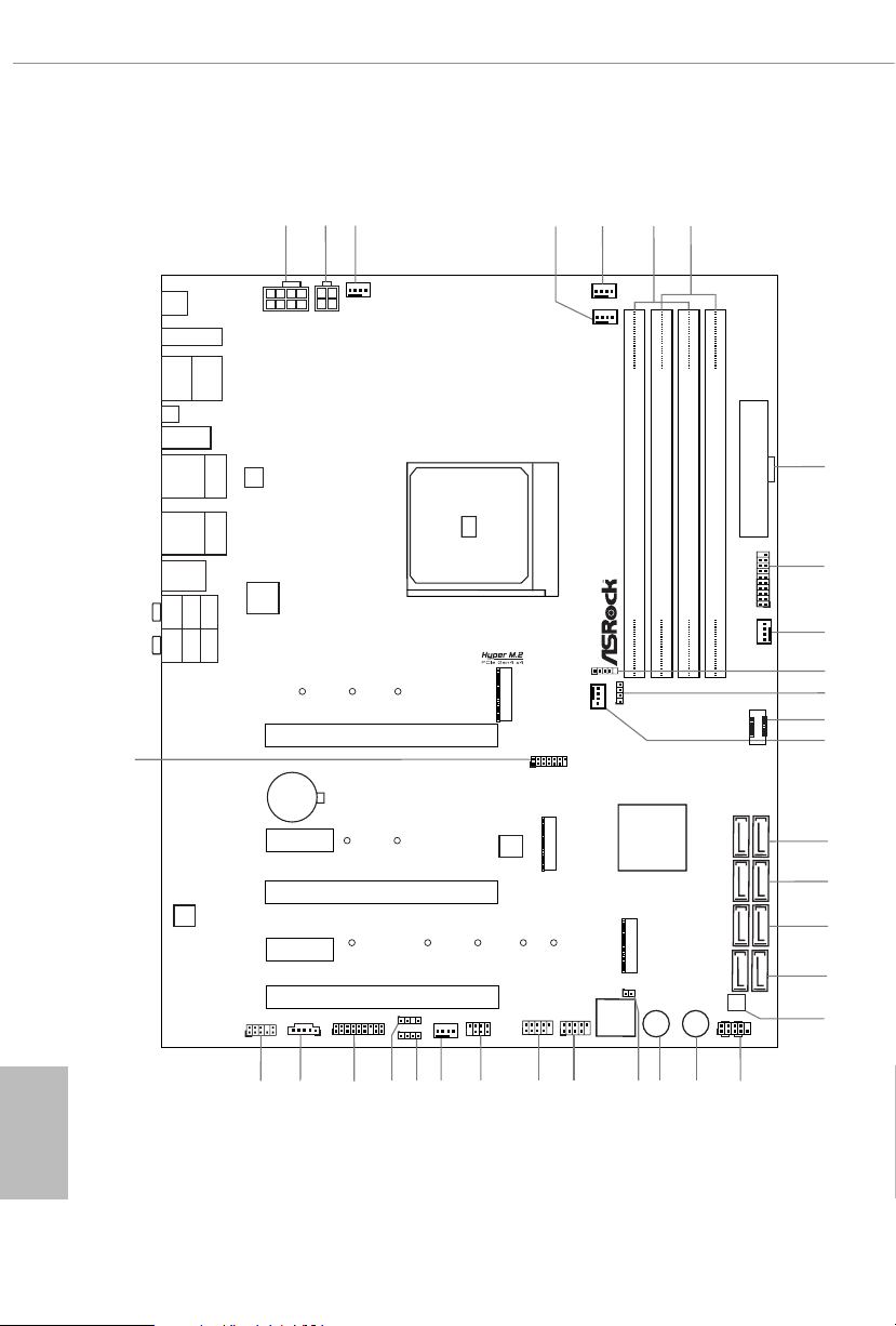
1.3 Motherboard Layout
English
8
Page 16

No. Description
1 8 pin 12V Power Connector (ATX12V1)
2 4 pin 12V Power Connector (ATX12V2)
3 Chassis / Waterpump Fan Connector (CHA_FAN3/WP)
4 CPU / Waterpump Fan Connector (CPU_FAN2/WP)
5 CPU Fan Connector (CPU_FAN1)
6 2 x 288-pin DDR4 DIMM Slots (DDR4_A1, DDR4_B1)
7 2 x 288-pin DDR4 DIMM Slots (DDR4_A2, DDR4_B2)
8 ATX Power Connector (ATXPWR1)
9 USB 3.2 Gen1 Header (USB3_7_8)
10 Chassis / Waterpump Fan Connector(CHA_FAN1/WP)
11 AMD LED Fan USB Header (USB_5)
12 AMD FAN LED Header (AMD_FAN_LED1)
13 Front Panel Type C USB 3.2 Gen2 Header (F_USB31_TC_1)
14 Chassis / Waterpump Fan Connector (CHA_FAN4/WP)
15 SATA3 Connectors (SATA3_1_2)
16 SATA 3 C on nectors (SATA 3_3 _4)
17 SATA3 Connectors (SATA3_5_6)
18 SATA3 Connectors (SATA3_7_8)
19 Clear CMOS Button (CLRCBTN2)
20 System Panel Header (PANEL1)
21 Power Button (PWRBTN1)
22 Reset Button (RSTBTN1)
23 Clear CMOS Jumper (CLRCMOS1)
24 USB 2.0 Header (USB_1_2)
25 USB 2.0 Header (USB_3_4)
26 Power LED and Spea ker Header (SPK_PLED1)
27 Chassis/Water Pump Fan Connector (CHA_FAN2/WP)
28 RGB LED Header (RGB_HEADER1)
29 Addressable LED Header (ADDR_LED1)
30 TPM Header (TPMS1)
31 underbolt AIC Header (TB1)
32 Front Panel Audio Header (HD_AUDIO1)
33 SPI TPM Header (SPI_TPM_J1)
X570 Phantom Gaming X
English
9
Page 17
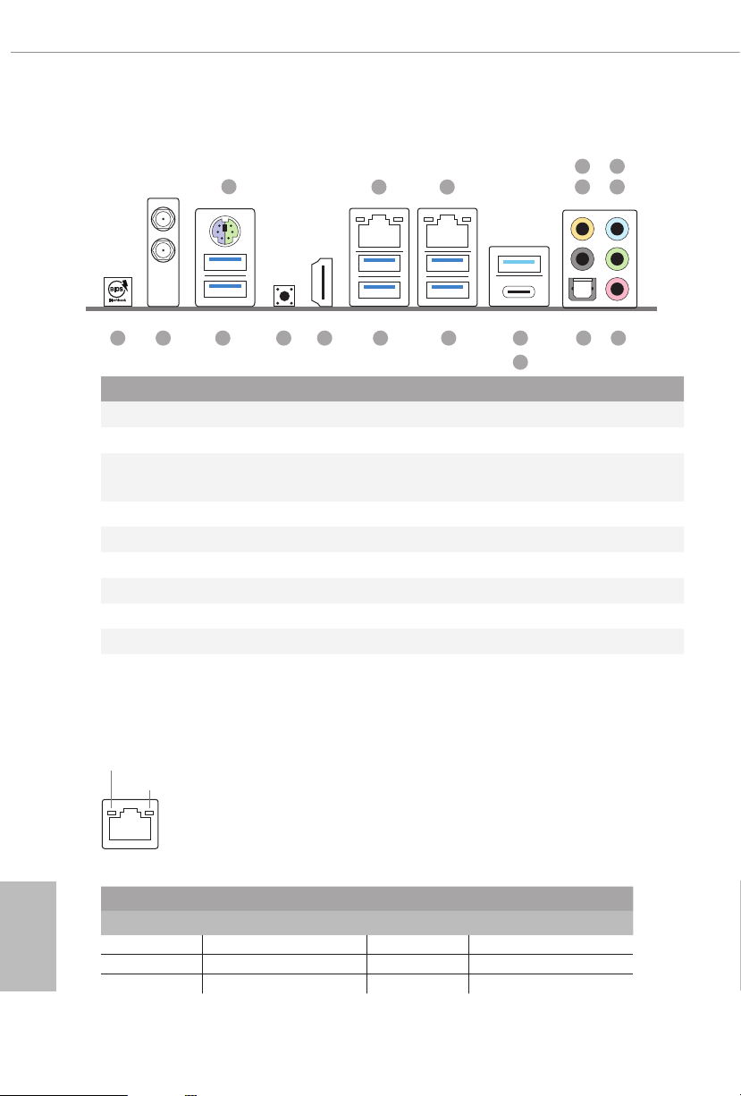
1.4 I/O Panel
6
1
2
3
547
151718 1314
No. Description No. Description
1 PS/2 Mouse/Keyboard Port (PS2_KB1) 10 USB 3.2 Gen2 Type-A Port (USB31_TA_1)
2 LAN RJ-45 Port (Intel® I211AT)* 11 USB 3.2 Gen2 Type-C Port (USB31_TC_1)
2.5G LAN RJ-45 Port(Dragon
3
RTL8125AG)**
4 Central / Bass (Orange) 13 USB 3.2 Gen1 Ports (USB3_3_4)
5 Rear Speaker (Black) 14 HDMI Port
6 Line In (Light Blue) 15 Clear CMOS Button
7 Front Speaker (Lime)*** 16 USB 3.2 Gen1 Ports (USB3_1_ 2)
8 Microphone (Pink) 17 Antenna Ports
9 Optical SPDIF Out Port 18 BIOS Flashback Button
* ere are two LEDs on each LAN port. Please refer to the table below for the LAN port LED indications.
ACT/LINK LED
SPEED LED
12 USB 3.2 Gen1 Ports (USB3_5_6)****
12
11
891016
English
10
LAN Por t
Activity / Link LED Speed LED
Status Description Status Description
O No Link O 10Mbps connection
Blinking Data Activity Orange 100Mbps connection
On Link Green 1Gbps connection
Page 18
X570 Phantom Gaming X
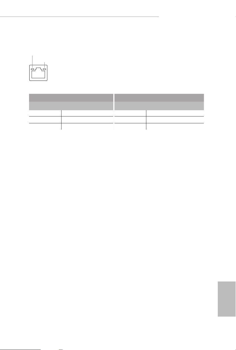
** ere are two LEDs on each LAN port. Please refer to the table below for the LAN port LED indications.
ACT/LINK LED
SPEED LED
LAN Por t
Activity / Link LED Speed LED
Status Description Status Description
O No Link O 10Mbps connection
Blinking Data Activity Orange 100Mbps/1Gbps connection
On Link Green 2.5Gbps connection
11
English
Page 19

***If you use a 2- channel speaker, plea se connect the speaker’s plug into “Front Speaker Jack”. See th e table below
for connection d etails in accordance w ith the type of speaker you use.
Audio Output
Channels
Front Speaker
(No. 7)
Rear Speaker
(No. 5)
Central / Bass
(No. 4)
2 V -- -- --
4 V V -- --
6 V V V --
8 V V V V
**** ACPI wake-up function is not supported on USB3_ 5_6 ports.
Line In
(No.6)
English
12
Page 20

X570 Phantom Gaming X
1.6 WiFi-802.11ax Module and ASRock WiFi 2.4/5 GHz
Antenna
WiFi-802.11ax + BT Module
is motherboard comes with an exclusive WiFi 802.11 a/b/g/n/ax + BT v5.0
module (pre-installed on the rear I/O panel) that oers support for WiFi 802.11 a/b/
g/n/ax connectivity standards and Bluetooth v5.0. WiFi + BT module is an easy-to-
use wireless local area network (WLAN) adapter to support WiFi + BT. Bluetooth
v5.0 standard features Smart Ready technology that adds a whole new class of
functionality into the mobile devices. BT 5.0 also includes Low Energ y Technology
and ensures extraordinary low power consumption for PCs. e 2T2R WiFi
solution sets a WiFi high speed standard and oers max link rate up to 2.4Gbps.
* e transmission speed may vary according to the environment.
13
English
Page 21

Chapter 2 Installation
is is an ATX form factor motherboard. Before you install the motherboard, study
the conguration of your chassis to ensure that the motherboard ts into it.
Pre-installation Precautions
Take note of the following precautions before you install motherboard components
or change any motherboard settings.
Make sure to unplug the power cord before installing or removing the motherboard.
•
Failure to do so may cause physical injuries to you and damages to motherboard
components.
In order to avoid damage from static electricity to the motherboard’s components,
•
NEVER place your motherboard directly on a carpet. Also remember to use a grounded
wrist strap or touch a safety grounded object before you handle the components.
Hold components by the edges and do not touch the ICs.
•
Whenever you uninstall any components, place them on a grounded anti-static pad or
•
in the bag that comes with the components.
When placing screws to secure the motherboard to the chassis, please do not over-
•
tighten the screws! Doing so may damage the motherboard.
English
14
Page 22
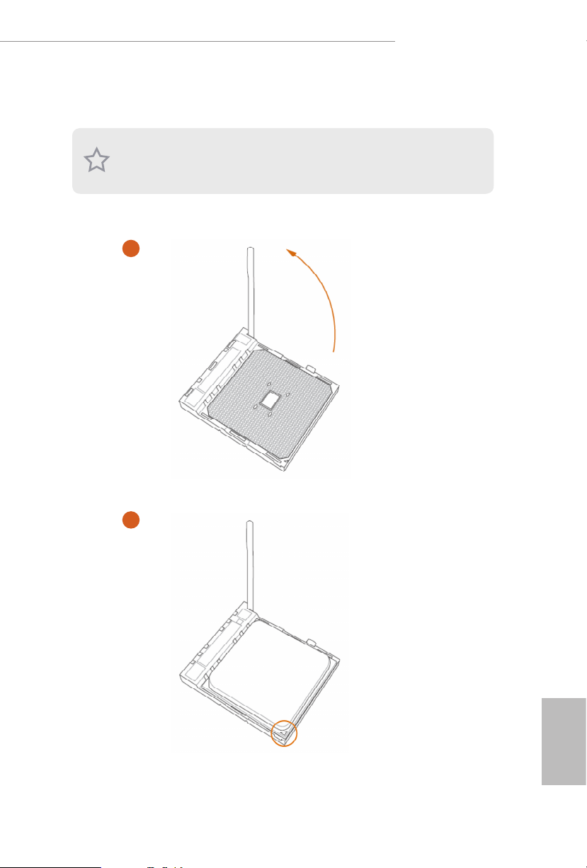
2.1 Installing the CPU
Unplug all power cables be fore installing the CPU.
1
X570 Phantom Gaming X
2
English
15
Page 23
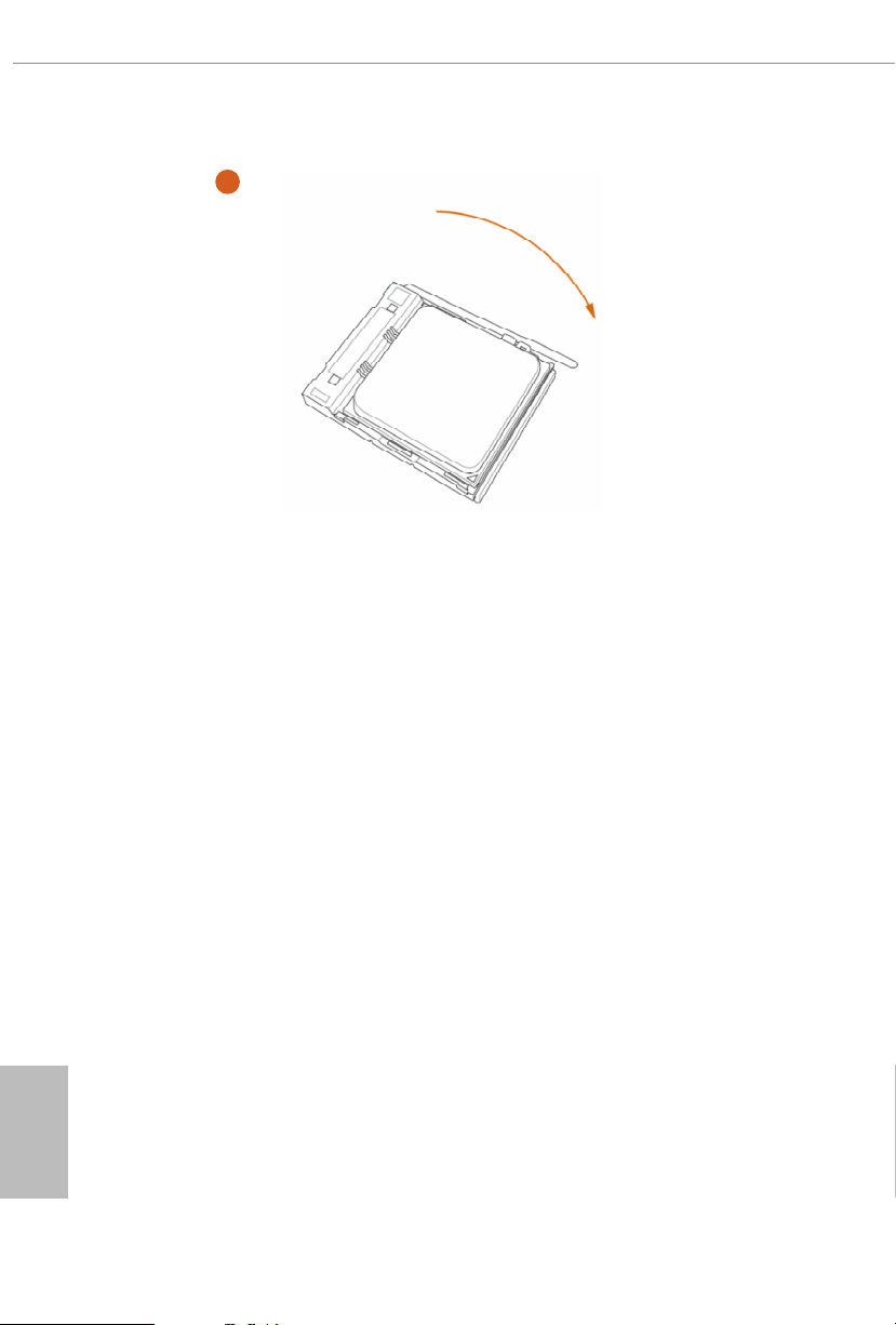
3
English
16
Page 24
X570 Phantom Gaming X
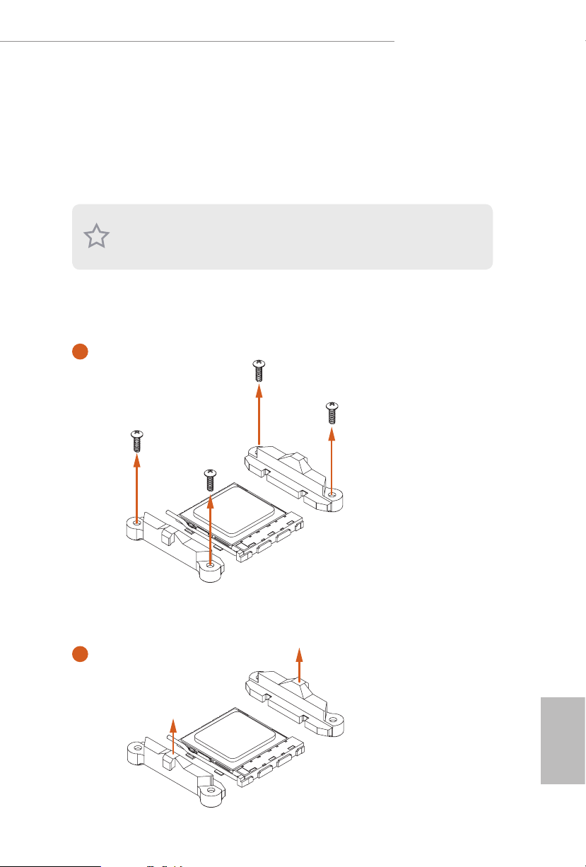
2.2 Installing the CPU Fan and Heatsink
Aer you install the CPU into this motherboard, it is necessary to install a larger
heatsink and cooling fan to dissipate heat. You also need to spray thermal grease
between the CPU and the heatsink to improve heat dissipation. Ma ke sure that the
CPU and the heatsink are securely fastened and in good contact with each other.
Please turn o the power or remove th e power cord before changing a CPU or heatsink.
Installing the CPU Box Cooler SR1
1
2
English
17
Page 25
3
English
18
4
1
N
FA
_
U
P
C
Page 26
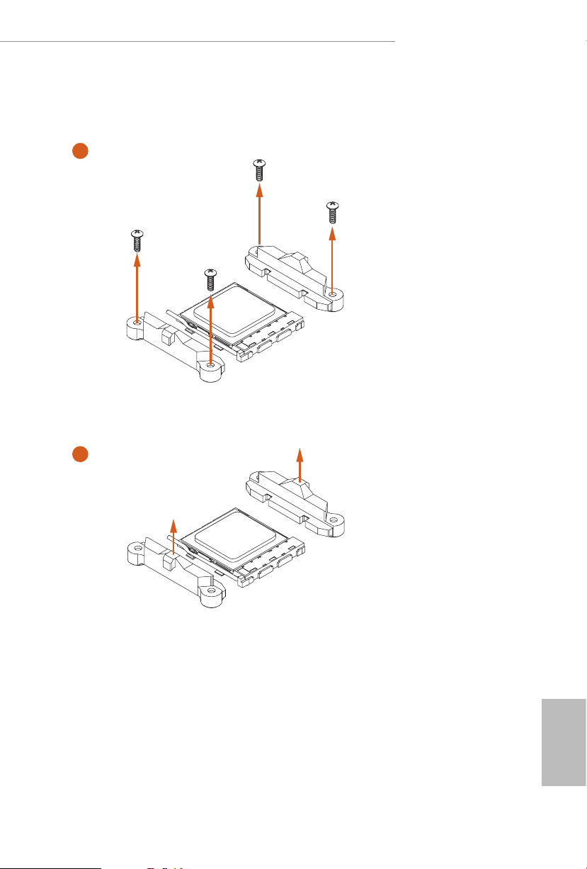
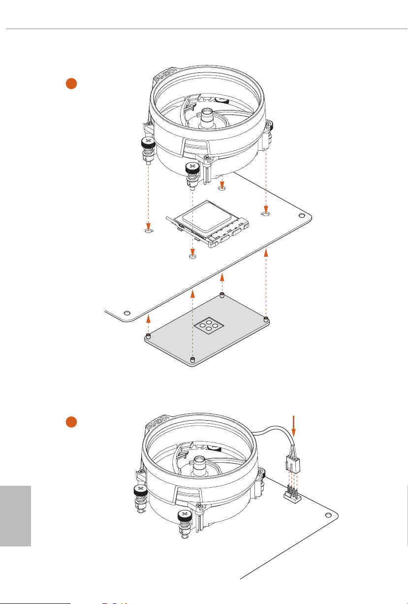
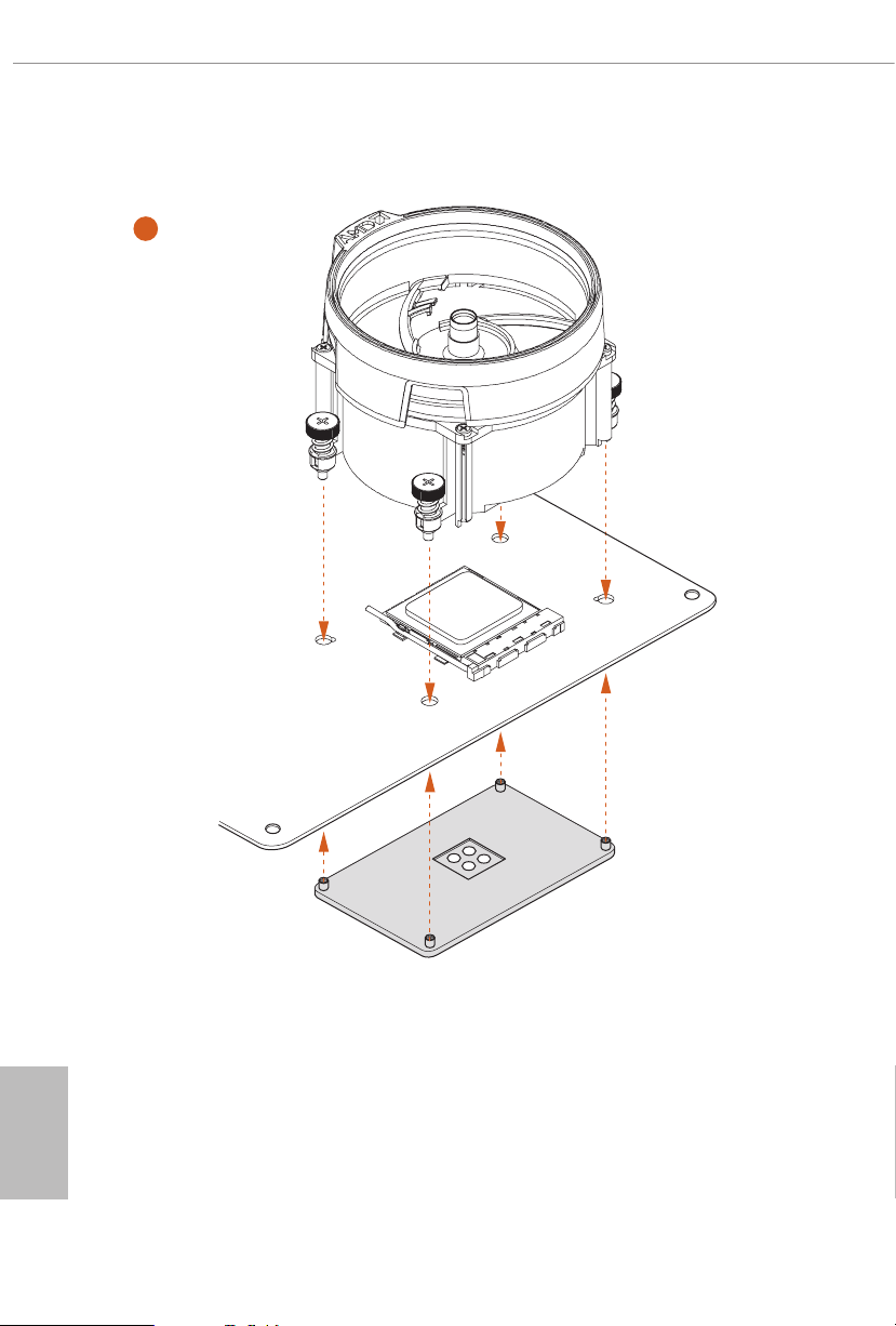
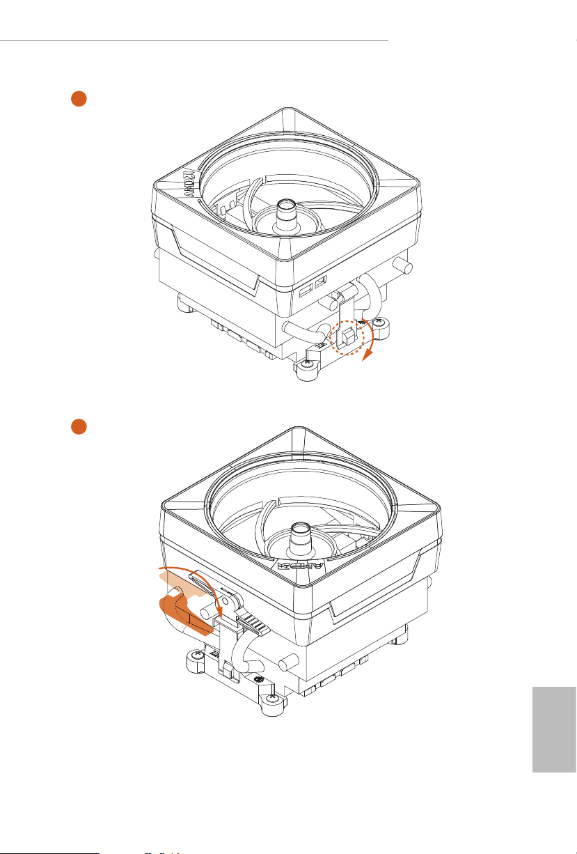
Installing the AM4 Box Cooler SR2
1
X570 Phantom Gaming X
2
English
19
Page 27
3
English
20
Page 28
X570 Phantom Gaming X
4
1
N
FA
_
U
P
C
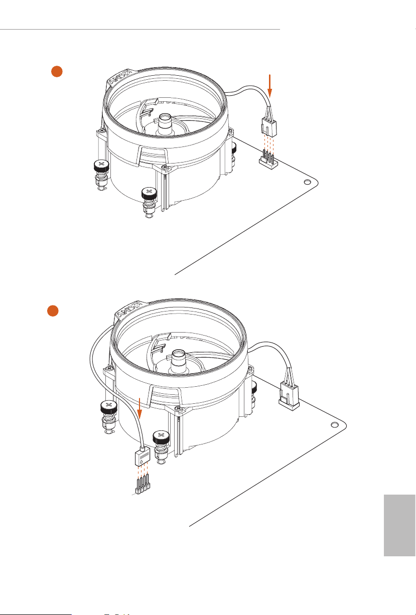
5
4-pin FAN cable
RGB LED Cable
1
N
FA
CPU_
1
D
E
L
_
N
FA
_
D
AM
+12V
*e diagrams shown here are for reference only. e headers might be in a dierent position on
your motherboard. Please refer to page 36 for the orientation of AMD Fan LED Header (AMD_
FAN_LED1).
English
21
Page 29
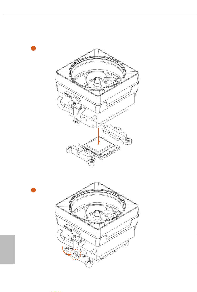
Installing the AM4 Box Cooler SR3
1
English
22
2
Page 30
X570 Phantom Gaming X
4
3
English
23
Page 31

5
FAN1
CPU_
English
24
Page 32

X570 Phantom Gaming X
6
1
N
FA
_
U
P
C
2
D
E
L
_
B
RG
+12V
or
7
1
N
FA
_
U
P
C
1
D
E
L
_
N
FA
_
D
AM
5
_
B
S
U
Please note that only one cable should be used at a time in this step.
If you select AMD_FAN_LED1, please install ASRock utility "ASRock Polychrome SYNC".
If you select USB connector, please install AMD utility "SR3 Settings Soware".
*e diagrams shown here are for reference only. e headers might be in a dierent position on your
motherboard. Please refer to page 36 for the orientation of AMD Fan LED Header (AMD_FAN_LED1)
and page 32 for the orientation of AMD LED Fan USB Header (USB_5).
25
English
Page 33

2.3 Installing Memory Modules (DIMM)
is motherboard provides four 288-pin DDR4 (Double Data Rate 4) DIMM slots,
and supports Dual Channel Memory Technology.
1. For dual channel cong uration , you always need to in stall identical (the same
brand, speed , size and chip-type) DDR4 DIMM pairs.
2. It is unable to activate Du al Channel Memory Technology with only one or three
memory module installed.
3. It is not allowed to install a DDR, DDR2 or DDR3 memory module into a DDR4
slot; otherwise, this motherboard and DIMM may be damaged.
4. We suggest that you install the memory modules on DDR4_A 2 and DDR4_B2 rst
for better DRAM compatibility on 2 DIMM s conguration.
AMD non-XMP Memory Frequency Support
Ryzen Series CPUs (Matisse):
English
26
UDIMM Memory Slot
A1 A2 B1 B2
Frequency
(Mhz)
- SR - - 3200
- DR - - 3200
- SR - SR 3200
- DR - DR 3200
SR SR SR SR 2933
SR/DR DR SR/DR DR 2667
SR/DR SR/DR SR/DR SR/DR 2667
Ryzen Series CPUs (Pinnacle Ridge):
UDIMM Memory Slot
A1 A2 B1 B2
- SR - - 2933
- DR - - 2933
- SR - SR 2933
- DR - DR 2933
SR SR SR SR 2933
SR/DR DR SR/DR DR 2667
SR/DR SR/DR SR/DR SR/DR 2133-2400
Frequency
(Mhz)
Page 34

Ryzen Series CPUs (Picasso):
UDIMM/SO-DIMMs Memory Slot
# of DIMMs on
the Channel
1 of 1 xR
1 of 2 xR-0
2 of 2 1R-1R 2133
2 of 2 2R-xR 1866
x=1 or 2
SR: Single rank DIMM, 1Rx4 or 1R x8 on DIMM module label
DR: Dua l rank DIMM, 2Rx4 or 2R x8 on DIMM module label
# of Ranks
per DIMM
1.20V
SR: 2933
DR: 2677
SR: 2667
DR: 2400
X570 Phantom Gaming X
27
English
Page 35

e DIMM only ts in one correct orie ntation. It will cause permanent dam age to
the motherboard and the DIMM if you force the DIMM into the slot at incor rect
orientation.
1
2
English
28
3
Page 36

X570 Phantom Gaming X
2.4 Expansion Slots (PCI Express Slots)
ere are 5 PCI Express slots on the motherboard.
Before installing an ex pansion card, please make sure that the power supply is switched o
or the power cord is unplug ged. Pl ease re ad the documentation of the expansion card and
make necessary hardware settings for the card before you start the installation.
PCIe slots:
PCIE1 (PCIe 4.0 x16 slot) is used for PCI Express x16 lane width graphics cards.
PCIE2 (PCIe 4.0 x1 slot) is used for PCI Express x1 lane width cards.
PCIE3 (PCIe 4.0 x16 slot) is used for PCI Express x8 lane width graphics cards.
PCIE4 (PCIe 4.0 x1 slot) is used for PCI Express x1 lane width cards.
PCIE5 (PCIe 4.0 x16 slot) is used for PCI Express x4 lane width graphics cards.
* If PCIE5 slot is occupied, M2 _3 will be disabled.
PCIe Slot Congurations
PCIE1 PCIE3 PCIE5
Ryzen Series CPUs (Matisse) Gen4x8 Gen4x8 Gen4x4
Ryzen Series CPUs (Pinnacle Ridge) Gen3x8 Gen3x8 Gen4x4
Gen3x8
Ryzen Series CPUs (Picasso)
N/A
For a better ther mal environme nt, ple ase connect a ch assis fan to the motherboard’s
chassis fan connector (CHA_ FAN1/WP, CHA_ FAN2/WP , CHA_FAN3/WP or
CHA_ FAN4/WP ) when using multiple graphics cards.
N/A
N/A
N/A
Gen4x4
English
29
Page 37

2.5 Jumpers Setup
e illustration shows how jumpers are setup. When the jumper cap is placed on
the pins, the jumper is “Short”. If no jumper cap is placed on the pins, the jumper is
“O pen”.
English
Clear CMOS Jumper
(CLRCMO S1)
(see p.8, No. 23)
CLRCMOS1 allows you to clear the data in CMOS. e data in CMOS includes
system setup information such as system password, date, time, and system setup
parameters. To clear and reset the system parameters to default setup, please
turn o the computer and unplug the power cord, then use a jumper cap to short
the pins on CLRCMOS1 for 3 seconds. Please remember to remove the jumper
cap aer clearing the CMOS. If you need to clear the CMOS when you just nish
updating the BIOS, you must boot up the system rst, and then shut it down
before you do the clear-CMOS action.
e Clear CMOS Button has the same function as the Cl ear CMOS jumper.
2-pin Jumper
Short: Clear CMOS
Open: Default
30
Page 38

2.6 Onboard Headers and Connectors
Onboard headers and connectors are NOT jump ers. Do NOT place jumper caps over these
heade rs and connectors. Placing jumper caps over the headers and connectors will cause
permanent damage to the motherboard.
X570 Phantom Gaming X
System Panel Header
(9-pi n PANEL1)
(see p.8, No. 20)
PWRBTN (Power Button):
Connec t to the power button on the ch assi s front panel. You may congure the way to tur n
o your system using the power button.
RESET (Reset B utton):
Connec t to the reset button on the ch assi s front panel. P ress the reset button to re start the
computer if the computer f reezes and fails to per form a normal restar t.
PLED (Syste m Power LED):
Connec t to the power status indicator on the chas sis front panel. e LED i s on when the
system is operating. e LED keeps blinking when the system is in S1/S3 sleep state. e
LED is o when the system is in S4 slee p state or powered o (S5).
HDLED (Ha rd Drive Activity LED):
Connec t to the hard drive ac tivity LED on the chassis front panel. e LED is on when the
hard drive is reading or wr iting data.
e front panel de sign may dier by chassis. A front panel module mainly consists of powe r
button, reset button , power LED, hard dr ive activity LED, speaker and etc. When connecting your ch assi s front panel module to thi s header, make sure the wire a ssignments and the
pin assignments are matched correctly.
1
PLED+
PLED-
HDLED-
HDLED+
PWRBTN#
GND
RESET#
GND
GND
Connect the power
button, reset button and
system status indicator on
the chassis to this header
according to the pin
assignments below. Note
the positive and negative
pins before connecting
the cables.
31
English
Page 39

Power LED and Speaker
1
+5V
DUMMY
PLED+
PLED+
PLED-
DUMMY
SPEAKER
DUMMY
GND
GND
P+
P-
USB_PWR
P+
P-
USB_PWR
1
1
1
USB_PWR
Header
(7-pin SPK_PLED1)
(see p.8, No. 26)
Please connect the
chassis power LED and
the chassis speaker to this
header.
Serial ATA3 Connectors
(SATA3_1_2:
see p.8, No. 15)
(SATA3_3_4:
see p.8, No. 16)
(SATA3_ 5_6:
see p.8, No. 17)
(SATA3_ 7_ 8:
see p.8, No. 18)
AMD LED Fan USB
Header
(4-pin USB_5)
(see p.8, No. 11)
USB 2.0 Headers
(9-pin USB_1_2)
(see p.8, No. 24)
(9-pin USB_3_4)
(see p.8, No. 25)
SATA3_2
SATA3_4
SATA3_6
SATA3_7
P-
ese eight SATA3
connectors support SATA
SATA3_1
data cables for internal
storage devices with up to
6.0 Gb/s data transfer rate.
SATA3_3
SATA3_5
SATA3_8
is header is used for
GND
P+
connecting the USB
connector on the AMD
SR3 Heatsink.
ere are two headers
on this motherboard.
Each USB 2.0 header can
support two ports.
English
32
USB 3.2 Gen1 Header
(19-pin USB3_7_8)
(see p.8, No. 9)
Vbus
IntA_PA_SSRX-
IntA_PA_SSRX+
IntA_PA_SSTX-
IntA_PA_SSTX+
IntA_PA_D-
IntA_PA_D+
VbusVbus
IntA_PB_SSRX-
IntA_PB_SSRX+
GND
IntA_PB_SSTX-
GND
IntA_PB_SSTX+
GND
IntA_PB_D-
GND
IntA_PB_D+
Dummy
ere is a header on this
motherboard. is USB
3.2 Gen1 header can
support two ports.
Page 40

X570 Phantom Gaming X
J_SENSE
OUT2_L
1
MIC_RET
PRESENCE#
GND
OUT2_R
MIC2_R
MIC2_L
OUT_RET
FAN_SPEED_CONTROL
4
GND
1 2 3 4
ype-C Cable
Front Panel Type C USB
3.2 Gen2 Header
(26-pin F_USB31_TC_1)
(see p.8, No. 13)
ere is one Front
Panel Type C USB 3.2
Gen2 Header on this
motherboard. is header
is used for connecting a
USB T
USB 3.2 Gen2 module for
additional USB 3.2 Gen2
ports.
Front Panel Audio Header
(9-pin HD_ AUDIO1)
(see p.8, No. 32)
1. High Denition Audio support s Jack Sensing, but the panel wire on the cha ssis must sup port HDA to function correctly. Ple ase fol low the instructions in our manual and chassis
manual to install your system.
2. If you use an AC’97 audio panel , please install it to th e front panel audio header by the
steps below:
A. Connect Mic_IN (MIC) to MIC2_ L.
B. Conne ct Audio_R (RIN) to OUT2_R and Audio_ L (LIN) to OUT2_ L.
C. Connect Ground (GND) to Ground (GND).
D. MIC_ RET and OUT_RET are for the HD audio panel only. You don’t ne ed to conn ect
them for the AC’97 audio panel .
E. To activate the front mic, go to the “FrontMic” Tab in the Realtek Control panel and
adjust “Recording Volume”.
is header is for
connecting audio devices
to the front audio panel.
Chassis Water Pump Fan
Connectors
(4-pin CHA_FAN1/WP)
(see p.8, No. 10)
(4-pin CHA_FAN2/WP)
(see p.8, No. 27)
(4-pin CHA_FAN3/WP)
(see p.8, No. 3)
CHA_FAN_SPEED
FAN_VOLTAGE
GND
FAN_VOLTAGE
FAN_SPEED
3
2
1
FAN_SPEED_CONTROL
is motherboard
provides four 4-Pin water
cooling
chassis
fan
connectors. If you plan to
connect a 3-Pin
chassis
water cooler fan, please
connect it to Pin 1-3.
English
33
Page 41

(4-pin CHA_FAN4/WP)
FAN_SPEED_CONTROL
1 2 3 4
FAN_SPEED_CONTROL
1 2 3 4
4
1
8 5
GND
1
(see p.8, No. 14)
2
3
4
FAN_VOLTAGE
CHA_FAN_SPEED
FAN_SPEED_CONTROL
English
34
CPU Fan Connector
(4-pin CPU_FAN1)
(see p.8, No. 5)
CPU Water Pump Fan
Connector
(4-pin CPU_FAN2/WP)
(see p.8, No. 4)
ATX Power Connector
(24-p i n ATX PWR1)
(see p.8, No. 8)
ATX 12V Power
Connector
(8-pin ATX12V1)
(see p.8, No. 1)
CPU_FAN_SPEED
FAN_VOLTAGE
GND
CPU_FAN_SPEED
FAN_VOLTAGE
GND
12
1
is motherboard pro”For
thevides a 4-Pin CPU fan
(Quiet Fan) connector.
If you plan to connect a
3-Pin CPU fan, please
connect it to Pin 1-3.
is motherboard
provides a 4-Pin water
cooling CPU fan
connector. If you plan
to connect a 3-Pin CPU
water cooler fan, please
connect it to Pin 1-3.
24
is motherboard pro-
vides a 24-pin ATX power
connector. To use a 20-pin
ATX power supply, please
plug it along Pin 1 and Pin
13
13.
is motherboard pro-
vides an 8-pin ATX 12V
power connector. To use a
4-pin ATX power supply,
please plug it along Pin 1
and Pin 5.
*Warning: Please make
sure that the power cable
connected is for the CPU
and not the graphics
card. Do not plug the
PCIe power cable to this
connector.
Page 42

X570 Phantom Gaming X
1
SPI_DQ3
ATX 12V Power
Connector
(4-pin ATX12V2)
(see p.8, No. 2)
LPC/TPM Header
(17-pi n TP MS1)
(see p.8, No. 30)
SPI TPM Header
(13 -pi n SPI_T PM _J1)
(see p.8, No. 33)
1
GN D
PC ICL K
+3.3V
SPI_CS0
SPI_DQ2
SMB _CL K_M AIN
SMB _DA TA_ MAI N
FRA M E
PC IRS T #
Dummy
CLK
RSMRST#
SPI_MISO
LAD 2
GN D
LAD 1
+3 V
LAD 3
LAD 0
SPI_MOSI
RST#
TPM_PIRQ
SPI_TPM_CS#
GND
Please connect an ATX
12V power supply to this
connector.
*e power supply plug
ts into this connector in
only one orientation.
is connector supports Trusted
Platform Module (TPM) system,
D
S_P WRD WN #
SER IRQ #
which can securely store keys,
GN
digital certicates, passwords,
and data. A TPM system also
helps enhance network security,
GN D
+3V S B
protects digital identities, and
ensures platform integrity.
is connector supports SPI
Trusted Platform Module (TPM)
system, which can securely store
keys, digital certicates, pass-
words, and data. A TPM system
also helps enhance network
security, protects digital
identities, and ensures platform
integrity.
underbolt AIC
Connector
(5-p i n TB1)
(see p.8, No. 31)
Please connect a underbolt™
add-in card (AIC) to the
underbolt AIC connector via
the GPIO cable.
*Please install the underbolt™
AIC card to PCIE4 (default
slot).
*For the further information,
please visit ww w.asrock.com.
English
35
Page 43

AMD FAN LED Header
D
1
1
1
(4- pi n AM D_FA N_
LED1)
(see p.8, No. 12)
B
R
G
12V
AMD FAN LED Header is used
to connect RGB LED
extension cable that comes with
AMD heatsink. e cable
connection allows users to choose
from various LED lighting
eects.
*e AMD Fan LED Header is
compatible with a regular RGB
LED stripe.
Caution: Never install the FAN
LED cable in the wrong orienta-
tion; otherwise, the cable may
be damaged.
English
36
RGB LED Header
(4-pi n RGB _HEA DER1)
(see p.8, No. 28)
Addressable LED Header
(3-pin A DDR_LE D1)
(see p.8, No. 29)
12V GRB
DO_ADDR
VOUT
is RGB header is used to
connect RGB LED extension
cable which allows
users to choose from various LED
lighting eects.
Caution: Never install the RGB
LED cable in the wrong orienta-
tion; otherwise, the cable may
be damaged.
*Please refer to page 72 for
further instructions on this
header.
is header is used to connect
GN
Addressable
LED extension cable
which allows users to choose
from various LED lighting
eects.
Caution: Never install the
Addressable LED cable in the
wrong orientation; otherwise,
the cable may be damaged.
*Please refer to page 73 for
further instructions on this
header.
Page 44

X570 Phantom Gaming X
2.7 Smart Switches
e motherboard has four smart switches: Power Button, Reset Button, Clear
CMOS Buttons and BIOS Flashback Switch, allowing users to quickly turn on/o
the system, reset the system, clear the CMOS values or ash the BIOS.
Power Button
(PWRBTN)
(see p.8, No. 21)
Reset Button
(RSTBTN)
(see p.8, No. 22)
Clear CMOS Buttons
(CLRCBTN1)
(see p.10, No. 15)
(CLRCBTN2)
(see p.8, No. 19)
is function i s workable only when you power o your computer and unplug the powe r
supp ly.
Power Button allows users
to quickly turn on/o the
system.
Reset Button allows
users to quickly reset the
system.
Clear CMOS Buttons
allow users to quickly
clear the CMOS values.
37
English
Page 45

BIOS Flashback Button
(BIOS_FB1)
BIOS Flashback Switch allows users
to ash the BIOS.
(see p.10, No. 18)
ASRock BIOS Flashback feature allows you to update BIOS without poweri ng on the system, even
without CPU.
To use the USB BIOS Flashback function, Plea se follow the steps below.
1. Download the latest BIOS le from ASRock's website : http://www.asrock.com.
2. Copy t he BIOS le to your USB ash drive. Please make sure the le system of
your USB ash drive must be FAT32.
3. Extract BIOS le from the zip le.
4. Rename the le to “creative.rom” and save it to the root director y of X: USB ash drive.
5. Plug the 24 pin power connector to t he motherboard. en turn on the power supply's AC
switch.
*ere is no need to power on t he system.
6. en plug your USB drive to the USB BIOS Flashback port.
7. Press the BIOS Flashback Switch for about three seconds. en the LED starts to blink.
8. Wait unti l the LED stops blink ing, i ndicating that BIOS ashing has been completed.
*If the LED light turns solid green, this means that the BIOS Flashback is not
operating properly. Please make sure that you plug t he USB drive to the USB BIOS Flashback
port.
English
38
USB BIOS Flashback port
Page 46

X570 Phantom Gaming X
2.8 Dr. Debug
Dr. Debug is used to provide code information, which makes troubleshooting even
easier. Please see the diagrams below for reading the Dr. Debug codes.
Code Description
0x10 PEI_CORE _STA RTED
0x11 PEI_CAR_CPU_INIT
0x15 PEI_CAR_NB_INIT
0x19 PEI_CAR_SB_INIT
0x 31 PEI_MEMORY_INSTALLED
0x32 PEI_CPU_INIT
0x33 PEI_CPU_CACHE_INIT
0x34 PEI_CPU_AP_INIT
0x35 PEI_CPU_BSP_SELECT
0x36 PEI_CPU_SMM_INIT
0x37 PEI_MEM_NB_INIT
0x3B PEI_MEM_SB_INIT
0x4F PEI_DXE_IPL_STARTED
0x60 DXE_CORE_STARTED
0x61 DXE_NVRAM_INIT
0x62 DXE_SBRU N_INI T
English
39
Page 47

0x63 DXE_ CPU_IN IT
0x68 DXE_NB_HB_INIT
0x69 DXE_NB_INIT
0x6A DXE_NB_SMM_INIT
0x70 DX E _SB _IN IT
0x71 DXE_SB_SMM_INIT
0x72 DXE_SB_DEVICES_INIT
0x78 DXE_ACPI_INIT
0x79 DXE_CSM_INIT
0x90 DXE_BDS_STARTED
0x91 DXE_BDS_CONNECT_DRIVERS
English
40
0x92 DXE_PCI_BUS_BEGIN
0x93 DXE_PCI_BUS_HPC_INIT
0x94 DXE_PCI_BUS_ENUM
0x95 DXE_PCI_BUS_REQUEST_RESOURCES
0x96 DXE_PCI_BUS_ASSIGN_RESOURCES
0x97 DXE_CON_OUT_CONNECT
0x98 DXE_CON_IN_CONNECT
Page 48

0x99 DXE_SIO_I NIT
0x 9A DXE_USB_BEGIN
0x9B DXE_USB_ RESET
0x9C DXE_USB_DETECT
0x9D DXE_USB_ENABLE
0xA0 DXE_IDE_BEGIN
0xA1 DXE_IDE_RESET
0xA2 DXE_IDE_DETECT
0xA3 DXE_IDE_ENABLE
X570 Phantom Gaming X
0xA4 DXE_SCSI_BEGIN
0xA5 DXE_SCSI_R ESET
0xA6 DXE_SCSI_DETECT
0xA7 DXE_SCSI _ENABLE
0xA8 DXE_SETUP_VER IFYING_PAS SWORD
0xA9 DXE_SETUP_START
0xAB DXE_SETUP_INPUT_WAIT
0xAD DXE_R EADY_TO_BOOT
0xAE DXE_LEGACY_BOOT
English
41
Page 49

0xAF DXE_EXIT_ BO OT_ SERVICES
0xB0 RT_SET_VIRTUAL _ADDRESS_MAP_BEGIN
0x B1 RT_SET_VIRTUAL_ADDRESS_ MAP_END
0xB2 DX E_LEGACY_OPROM _IN IT
0xB3 DXE_RESET_SYSTEM
0xB4 DXE_USB _HOTPLUG
0xB5 DXE_PCI_BUS_HOTPLUG
0xB6 DXE_NVRAM_CLEANUP
0xB7 DXE_CONFIGURATION_RESET
0xF0 PEI _RECOVERY_AUTO
0xF1 PEI_RECOVERY_USER
English
42
0xF2 PE I_R ECOVE RY_ STARTED
0xF3 PEI_RECOVERY_CAPSULE_FOUND
0xF4 PEI_RECOVERY_CAPSULE_LOADED
0xE0 PEI_S3_STARTED
0xE1 PEI_S3_BOOT_SCRIPT
0xE2 PEI_S3_VIDEO_REPOST
Page 50

0xE3 PEI _ S3 _OS _WAK E
0x50 PEI_MEMORY_INVALID_TYPE
0x53 PEI_MEMORY_NOT_DETECTED
0x55 PEI_MEMORY_NOT_INSTALLED
0x57 PEI_CPU_MISMATCH
0x58 PEI_CPU_SELF_TEST_FAILED
0x59 PEI_CPU_NO_MICROCODE
0x5A PEI_CPU_ERROR
0x5B PE I_R ESET_ NOT_AVAILABLE
X570 Phantom Gaming X
0xD0 DXE_CPU_ERROR
0x D1 DXE_NB_ERROR
0xD2 DXE_SB_ERROR
0xD3 DXE_ARCH_PROTOCOL_NOT_AVAILABLE
0xD4 DXE_PCI_BUS_OUT_OF_RESOURCES
0xD5 DXE _LEGACY_OPROM_ NO _SPACE
0xD6 DXE_NO_CON_OUT
0xD7 DXE_NO_CON_IN
English
43
Page 51

0xD8 DXE_IN VALID_PAS SWORD
0xD9 DXE_BOOT_OPTION_LOAD_ERROR
0x DA DXE_BOOT_OPTION_FAILED
0xDB DXE_FLASH_UPDATE_FAILED
0xDC DXE _RESET_ NOT_AVAILABLE
0xE8 PEI_MEMORY_S3_RESUME_FAILED
0xE9 PEI_S3_RESUME_PPI_NOT_FOUND
0xEA PEI_ S3_BOOT_SCR IPT_ER ROR
0xEB PEI_S3_OS_WAKE_ERROR
English
44
Page 52

X570 Phantom Gaming X
2.9 SLITM and Quad SLITM Operation Guide
is motherboard supports NVIDIA® SLITM and Quad SLITM (Scalable Link
Interface) technology that allows you to install up to two identical PCI Express x16
graphics cards.
Requirements
1. You should only u se identical SLITM-ready g raphics cards that are NV IDIA® certied.
2. Make sure that your gra phics c ard driver supports NVIDIA® SLITM technology. Download
the drivers from the NVIDIA® website: www.nvidia.com
3. Make sure that your power supply unit (PSU) can provide at lea st the minimum power
your system requires. It is recommended to use a NV IDIA® certied PSU. Please refer to
the NVIDIA® website for details.
2.9.1 Installing Two SLITM-Ready Graphics Cards
Step 1
Insert one graphics card into PCIE1 slot
and the other graphics card to PCIE3 slot.
Make sure that the cards are properly
seated on the slots.
Step 2
If required, connect the auxiliary power
source to the PCI Express graphics cards.
English
45
Page 53

SLI_HB_Bridge_2S Card
ASRock SLI_HB_Bridge_2S Card
Step 3
Align and insert the ASRock SLI_HB_
Bridge_2S Card to the goldngers on each
graphics card. Make sure the ASRock SLI_
HB_Bridge_2S Card is rmly in place.
Step 4
Connect a VGA cable or a DVI cable to the
monitor connector or the DVI connector of
the graphics card that is inserted to PCIE1
slot.
English
46
Page 54

X570 Phantom Gaming X
2.9.2 Driver Installation and Setup
Install the graphics card drivers to your system. Aer that, you can enable the
Multi-Graphics Processing Unit (GPU) in the N VIDIA® nView system tray utilit y.
Please follow the below procedures to enable the multi-GPU.
For SLITM and Quad SLITM mode
Step 1
Double-click the NVIDIA Control Panel
icon in the Windows® sy stem tray.
Step 2
In the le pane, click Set SLI and PhysX
conguration. en select Maximize 3D
performance and click Apply.
Step 3
Reboot your system.
Step 4
You can freely enjoy the benets of SLITM
or Quad SLITM.
47
English
Page 55

2.10 CrossFireXTM , 3-Way CrossFireXTM and Quad CrossFireXTM
Operation Guide
is motherboard supports CrossFireXTM, 3-way CrossFireXTM and Quad
CrossFireXTM that allows you to install up to three identical PCI Express x16
graphics cards.
1. You should only use identical CrossFireXTM-ready g raphics cards that are AM D
certied.
2. Make sure that your gra phics c ard driver supports AMD CrossFireXTM technology.
Download the drivers from the A MD’s website: www.amd.com
3. Make sure that your power supply unit (PSU) can provide at lea st the minimum
power your syste m require s. It is recommended to use a AMD certied PSU. Plea se
refer to the AMD’s website for d etail s.
4. If you pair a 12-pipe CrossFireXTM Edition card with a 16-pipe card, both cards will
operate a s 12-pipe cards while in CrossFireXTM mode.
5. Dierent CrossFireXTM cards may require dierent method s to enable CrossFireXTM. Please refer to A MD graphics card manuals for de tailed installation guide.
2.10.1 Installing Two CrossFireXTM-Ready Graphics Cards
Step 1
Insert one graphics card into PCIE1 slot
and the other graphics card to PCIE3 slot.
Make sure that the cards are properly
seated on the slots.
English
48
CrossFire Bridge
Step 2
Connect two graphics cards by installing
a CrossFire Bridge on the CrossFire Bridge
Interconnects on the top of the graphics
cards. (e CrossFire Bridge is provided
with the graphics card you purchase, not
bundled with this motherboard. Please
refer to your graphics card vendor for
deta ils .)
Page 56

X570 Phantom Gaming X
Step 3
Connect a VGA cable or a DVI cable to the
monitor connector or the DVI connector of
the graphics card that is inserted to PCIE1
slot.
49
English
Page 57

2.10.2 Installing Three CrossFireXTM-Ready Graphics Cards
Step 1
Insert one graphics card into PCIE1 slot,
another graphics card to PCIE3 slot, and
the other graphics card to PCIE5 slot.
Make sure that the cards are properly
seated on the slots.
Step 2
Use one CrossFire Bridge to connect
CrossFire Bridge
the graphics cards on PCIE1 and PCIE3
slots, and use the other CrossFire Bridge
to connect the graphics cards on PCIE3
and PCIE5 slots. (e CrossFire Bridge
is provided with the graphics card
you purchase, not bundled with this
motherboard. Please refer to your graphics
card vendor for details.)
English
50
Step 3
Connect a VGA cable or a DVI cable to the
monitor connector or the DVI connec-
tor of the graphics card that is inserted to
PCIE1 slot.
Page 58

X570 Phantom Gaming X
2.10.3 Driver Installation and Setup
Step 1
Power on your computer and boot into OS.
Step 2
Remove the AMD drivers if you have any VGA drivers installed in your system.
e Catalyst Unins talle r is an optional do wnload. We recommend us ing this utility
to uninstall any previously installed Catalyst drivers prior to installation. Pl ease
check A MD’s website for AMD driver update s.
Step 3
Install the required drivers and CATALYST Control Center then restart your
computer. Please check AMD’s website for details.
Step 4
Double-click the AMD Catalyst Control
AMD Catalyst Control Center
Center icon in the Windows® sy stem tray.
Step 5
In the le pane, click Performance and
then AMD CrossFireXTM. en select
Enable AMD CrossFireX and click Apply.
Select the GPU number according to your
graphics card and click Apply.
English
51
Page 59

2.11 M.2_SSD (NGFF) Module Installation Guide (M2_1)
3
The M.2, a lso known as the Next Generation Form Factor (NGFF), is a sma ll size a nd
versatile card edge connector that aims to replace mPCIe and mSATA. e Hy per M.2
Socket (M2_1) supports SATA3 6.0 Gb/s module and M.2 PCI E xpress module up to
Gen4x4 (64 Gb/s) (with Matisse) or Gen3x4 (32 Gb/s) (with Pinnacle Ridge and Picasso)*
Installing the M.2_SSD (NGFF) Module
Step 1
Prepare a M.2_SSD (NGFF) module
and the screw.
English
2
1
ABC
No. 1 2 3
Nut Location A B C
PCB Length 4.2cm 6cm 8cm
Module Type Type 224 2 Ty pe2260 Ty pe 2 28 0
Step 2
Depending on the PCB type and
length of your M.2_SSD (NGFF)
module, nd the corresponding nut
location to be used.
52
Page 60

X570 Phantom Gaming X
1
2
1
Step 3
Before installing a M.2 (NGFF) SSD
module, please loosen the screws to
remove the M.2 heatsink.
*Please remove the protective lms
on the bottom side of the M.2
1
1
heatsink before you install a M.2
SSD module.
Step 4
Prepare the M.2 stando that comes
with the package. en hand tighten
the stando into the desired nut
location on the motherboard. Align
ABC
and gently insert the M.2 (NGFF)
SSD module into the M.2 slot. Please
be aware that the M.2 (NGFF) SSD
module only ts in one orientation.
ABC
o
20
Step 5
Tighten the screw with a screwdriver
to secure the module into place.
NUT1NUT2C
Please do not overtighten the screw
as this might damage the module.
English
53
Page 61

M.2_SSD (NGFF) Module Support List
Vendor Interface P/N
SanDisk PCIe SanDisk-SD6PP4M-128G( Gen2 x2)
Intel PCIe INTEL 6000P-SSDPEKKF256G7 (nvme)
Intel PCIe INTEL 6000P-SSDPEKKF512G7 (nvme)
Intel PCIe SSDPEKKF512G7 NVME / 512GB
Intel SATA 540S-SSDSCKKW240H6 / 240GB
Kingston PCIe Kingston SHPM2280P2 / 240G (Gen2 x4)
Samsung PCIe Samsung XP941-MZHPU512HCGL(Gen2x4)
Samsung PCIe SM951 (NVME) / 512GB
Samsung PCIe SM951 (M ZHPV512HDGL) / 512GB
ADATA SATA ADATA - AXNS381E-128GM-B
ADATA PCIe ASX8000NP-512GM-C / 512GB
ADATA PCIe ASX7000NP-512GT-C / 512GB
ADATA SATA ASU800NS38-512GT-C / 512GB
Crucial SATA Crucial-CT240M500SSD4-240GB
ezlink SATA ezlink P51B-80-120GB
Intel SATA INTEL 540S-SSDSCKKW240H6-240GB
Kingston SATA Kingston SM2280S3G2/120G - Win8.1
Kingston SATA Kingston-RBU-SNS8400S3 / 180GD
Kingston PCIe SKC1000/480G
Kingston PCIe SKC1000/960GB NVME
LITEON SATA LI TEON LJH-25 6V2G -25 6GB (2260)
PLEXTOR SATA PLEXTOR PX-128M6G-2260-128GB
PLEXTOR SATA PLEXTOR PX-128M7VG-128GB
PLEXTOR PCIe PX-512M8Pe G/ 512GB
SanDisk SATA SanDisk X400-SD8SN8U-128G
SanDisk SATA Sandisk Z400s-SD8SNAT-128G-1122
SanDisk SATA SanDisk-SD6SN1M-128G
Tra nscend SATA Transcend TS256GMTS800-256GB
Tra nscend SATA TS512GMTS800 / 512GB
V-Col or SATA V- C olor 120G
V-Col or SATA V- C olor 240G
WD SATA WD GREEN WDS240G1G0B-00RC30
WD PCIe WDS512G1X0C -00EN X0 (N VME) / 512GB
English
54
For the latest updates of M.2_SSD (NFGG) module support list, please visit our website
for details: http://www.asrock.com
Page 62

X570 Phantom Gaming X
2.12 M.2_SSD (NGFF) Module Installation Guide (M2_2)
The M.2, a lso known as the Next Generation Form Factor (NGFF), is a sma ll size a nd
versatile card edge connector that aims to replace mPCIe and mSATA. e Hy per M.2
Socket (M2_2) supports M.2 PCI Express module up to Gen4x4 (64 Gb/s).
Installing the M.2_SSD (NGFF) Module
Step 1
is motherboard supports M.2_SSD
(NGFF) module t ype 2260 and 2280
only. Prepare a proper PCB lenth of
module, the screw and the stando.
Step 2
Depending on the PCB type and
length of your M.2_SSD (NGFF)
2
1
module, nd the corresponding nut
location to be used.
A
B
No. 1 2
Nut Location A B
PCB Length 6cm 8cm
Module Type Type22 60 Type 228 0
English
55
Page 63

1
2
1
Step 3
Before installing a M.2 (NGFF) SSD
module, please loosen the screws to
remove the M.2 heatsink.
*Please remove the protective lms
1
on the bottom side of the M.2
heatsink before you install a M.2
SSD module.
1
Step 4
Prepare the M.2 stando that comes
with the package. en hand tighten
the stando into the desired nut
location on the motherboard. Align
AB
and gently insert the M.2 (NGFF)
SSD module into the M.2 slot. Please
be aware that the M.2 (NGFF) SSD
module only ts in one orientation.
English
56
AB
o
20
Step 5
Tighten the screw with a screwdriver
to secure the module into place.
Please do not overtighten the screw
NUT1NUT2B
as this might damage the module.
Page 64

X570 Phantom Gaming X
M.2_SSD (NGFF) Module Support List
Vendor Interface P/N
SanDisk PCIe SanDisk-SD6PP4M-128G( Gen2 x2)
Intel PCIe INTEL 6000P-SSDPEKKF256G7 (nvme)
Intel PCIe INTEL 6000P-SSDPEKKF512G7 (nvme)
Intel PCIe SSDPEKKF512G7 NVME / 512GB
Kingston PCIe Kingston SHPM2280P2 / 240G (Gen2 x4)
Samsung PCIe Samsung XP941-MZHPU512HCGL(Gen2x4)
Samsung PCIe SM951 (NVME) / 512GB
Samsung PCIe SM951 (M ZHPV512HDGL) / 512GB
ADATA PCIe ASX8000NP-512GM-C / 512GB
ADATA PCIe ASX7000NP-512GT-C / 512GB
Kingston PCIe SKC1000/480G
Kingston PCIe SKC1000/960GB NVME
PLEXTOR PCIe PX-512M8Pe G/ 512GB
WD PCIe WDS512G1X0C -00EN X0 (N VME) / 512GB
For the latest updates of M.2_SSD (NFGG) module support list, please visit our website
for details: http://www.asrock.com
57
English
Page 65

2.13 M.2_SSD (NGFF) Module Installation Guide (M2_3)
5
e M.2, also known as the Next Generation Form Factor (NGFF), is a small size and
versatile card edge connector that aims to replace mPCIe and mSATA. e Hyper M.2
Socket (M2_3) supports M.2 SATA3 6.0 Gb/s module and M.2 PCI Express module up to
Gen4x4 (64 Gb/s).
* If M2_3 is occupied, PCIE5 slot will be disabled.
Installing the M.2_SSD (NGFF) Module
Step 1
Prepare a M.2_SSD (NGFF) module
and the screw.
English
4
3
Depending on the PCB type and
length of your M.2_SSD (NGFF)
module, nd the corresponding nut
Step 2
2
1
A
BCDE
location to be used.
No. 1 2 3 4 5
Nut Location A B C D E
PCB Length 3cm 4.2cm 6cm 8cm 11cm
Module Type Type223 0 Ty pe 22 42 Ty pe 2260 Ty pe 2280 Type 2 2110
58
Page 66

X570 Phantom Gaming X
1
2
1
Step 3
Before installing a M.2 (NGFF) SSD
module, please loosen the screws to
remove the M.2 heatsink.
*Please remove the protective lms on
the bottom side of the M.2 heatsink
1
1
before you install a M.2 SSD module.
Step 4
Prepare the M.2 stando that comes
with the package. en hand tighten
the stando into the desired nut
ABCDE
location on the motherboard. Align
and gently insert the M.2 (NGFF)
SSD module into the M.2 slot. Please
be aware that the M.2 (NGFF) SSD
module only ts in one orientation.
o
ABCDE
20
Step 5
Tighten the screw with a screwdriver
to secure the module into place.
Please do not overtighten the screw as
NUT1NUT2DE
this might damage the module.
English
59
Page 67

Vendor Interface P/N
M.2_SSD (NGFF) Module Support List
SanDisk PCIe SanDisk-SD6PP4M-128G( Gen2 x2)
Intel PCIe INTEL 6000P-SSDPEKKF256G7 (nvme)
Intel PCIe INTEL 6000P-SSDPEKKF512G7 (nvme)
Intel PCIe SSDPEKKF512G7 NVME / 512GB
Intel SATA 540S-SSDSCKKW240H6 / 240GB
Kingston PCIe Kingston SHPM2280P2 / 240G (Gen2 x4)
Samsung PCIe Samsung XP941-MZHPU512HCGL(Gen2x4)
Samsung PCIe SM951 (NVME) / 512GB
Samsung PCIe SM951 (M ZHPV512HDGL) / 512GB
ADATA SATA ADATA - AXNS381E-128GM-B
ADATA PCIe ASX8000NP-512GM-C / 512GB
ADATA PCIe ASX7000NP-512GT-C / 512GB
ADATA SATA ASU800NS38-512GT-C / 512GB
Crucial SATA Crucial-CT240M500SSD4-240GB
ezlink SATA ezlink P51B-80-120GB
Intel SATA INTEL 540S-SSDSCKKW240H6-240GB
Kingston SATA Kingston SM2280S3G2/120G - Win8.1
Kingston SATA Kingston-RBU-SNS8400S3 / 180GD
Kingston PCIe SKC1000/480G
Kingston PCIe SKC1000/960GB NVME
LITEON SATA LI TEON LJH-25 6V2G -25 6GB (2260)
PLEXTOR SATA PLEXTOR PX-128M6G-2260-128GB
PLEXTOR SATA PLEXTOR PX-128M7VG-128GB
PLEXTOR PCIe PX-512M8Pe G/ 512GB
SanDisk SATA SanDisk X400-SD8SN8U-128G
SanDisk SATA Sandisk Z400s-SD8SNAT-128G-1122
SanDisk SATA SanDisk-SD6SN1M-128G
Tra nscend SATA Transcend TS256GMTS800-256GB
Tra nscend SATA TS512GMTS800 / 512GB
V-Col or SATA V- C olor 120G
V-Col or SATA V- C olor 240G
WD SATA WD GREEN WDS240G1G0B-00RC30
WD PCIe WDS512G1X0C -00EN X0 (N VME) / 512GB
English
60
For the latest updates of M.2_SSD (NFGG) module support list, please visit our website
for details: http://www.asrock.com
Page 68

X570 Phantom Gaming X
Chapter 3 Software and Utilities Operation
3.1 Installing Drivers
e Support CD that comes with the motherboard contains necessary drivers and
useful utilities that enhance the motherboard’s features.
Running The Support CD
To begin using the support CD, insert the CD into your CD-ROM drive. e CD
automatically displays the Main Menu if “AUTORUN” is enabled in your computer.
If the Main Menu does not appear automatically, locate and double click on the le
“ASRSETUP.EXE” in the Support CD to display the menu.
Drivers Menu
e drivers compatible to your system will be auto-detected and listed on the
support CD driver page. Please click Install All or follow the order from top to
bottom to install those required drivers. erefore, the drivers you install can work
properly.
Utilities Menu
e Utilities Menu shows the application soware that the motherboard supports.
Click on a specic item then follow the installation wizard to install it.
61
English
Page 69

3.2 Phantom Gaming Tuning
Phantom Gaming Tuning is ASRock ’s multi purpose soware suite with a new
interface, more new features and improved utilities.
3.2.1 Installing Phantom Gaming Tuning
Phantom Gaming Tuning can be downloaded from ASRock Live Update & APP
Shop. Aer the installation, you will nd the icon “Phantom Gaming Tuning“ on
your desktop. Double-click the “Phantom Gaming Tuning“ icon, Phantom
Gaming Tuning main menu will pop up.
3.2.2 Using Phantom Gaming Tuning
ere are ve sections in Phantom Gaming Tuning main menu: Operation Mode,
OC Tweaker, System Info, FAN-Tastic Tuning and Settings.
Operation Mode
Choose an operation mode for your computer.
English
62
Page 70

OC Tw eaker
Congurations for overclocking the system.
X570 Phantom Gaming X
System Info
View information about the system.
*e System Browser tab may not appear for certain models.
English
63
Page 71

FAN-Tastic Tuning
Congure up to ve dierent fan speeds using the graph. e fans will automatically shi
to the next speed level when the assigned temperature is met.
Settings
Congure ASRock Phantom Gaming Tuning. Click to select "Auto run at Windows
Startup" if you want Phantom Gaming Tuning to be launched when you start up the
Windows operating system.
English
64
Page 72

X570 Phantom Gaming X
3.3 ASRock Live Update & APP Shop
e ASRock Live Update & APP Shop is an online store for purchasing and
downloading soware applications for your ASRock computer. You can quickly and
easily install various apps and support utilities. With ASRock Live Update & APP
Shop, you can optimize your system and keep your motherboard up to date simply
with a few clicks.
Double-click on your desktop to access ASRock Live Update & APP Shop
utility.
*You need to be connected to the Internet to download apps f rom the ASRock Live Update & APP Shop.
3.3.1 UI Overview
Category Panel
Information Panel
Category Panel: e category panel contains several category tabs or buttons that
when selected the information panel below displays the relative information.
Information Panel: e information panel in the center displays data about the
currently selected category and allows users to perform job-related tasks.
Hot News: e hot news section displays the various latest news. Click on the image
to visit the website of the selected news and know more.
Hot News
English
65
Page 73

3.3.2 Apps
When the "Apps" tab is selected, you will see all the available apps on screen for you
to download.
Installing an App
Step 1
Find the app you want to install.
e most recommended app appears on the le side of the screen. e other various
apps are shown on the right. Please scroll up and down to see more apps listed.
You can check the price of the app and whether you have already intalled it or not.
English
66
- e red icon displays the price or "Free" if the app is free of charge.
- e green "Installed" icon means the app is installed on your computer.
Step 2
Click on the app icon to see more details about the selected app.
Page 74

X570 Phantom Gaming X
Step 3
If you want to install the app, click on the red icon to start downloading.
Step 4
When installation completes, you can nd the green "Installed " icon appears on the
upper right corner.
To uninstall it, simply click on the trash can icon .
*e trash icon may not appear for certain apps.
English
67
Page 75

Upgrading an App
You can only upgrade the apps you have already installed. When there is an
available new version for your app, you will nd the mark of "New Version"
appears below the installed app icon.
Step 1
Click on the app icon to see more details.
Step 2
Click on the yellow icon to start upgrading.
English
68
Page 76

X570 Phantom Gaming X
3.3.3 BIOS & Drivers
Installing BIOS or Drivers
When the "BIOS & Drivers" tab is selected, you will see a list of recommended or
critical updates for the BIOS or drivers. Please update them all soon.
Step 1
Please check the item information before update. Click on to see more details.
Step 2
Click to select one or more items you want to update.
Step 3
Click Update to start the update process.
English
69
Page 77
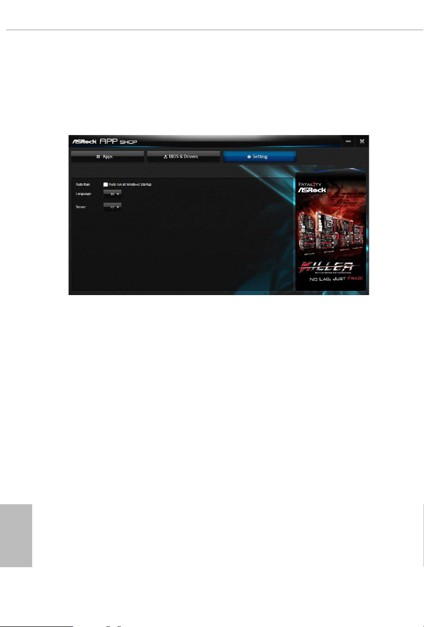
3.3.4 Setting
In the "Setting" page, you can change the language, select the server location, and
determine if you want to automatically run the ASRock Live Update & APP Shop
on Windows startup.
English
70
Page 78

X570 Phantom Gaming X
1 2 3 4 5
3.4 Creative SoundBlaster Cinema5
e SoundBlasterTM Cinema5, powered by the SBX Pro Studio technologies, is designed
to bring the same great audio experience found in live performances, lms, and record-
ing studios to the PC. With this utility, you can easily enhance your audio environment
in ve modes, including Headphones, Speakers, Music, Movie, Game, Voice and Custom.
ere are ve functions in SoundBlasterTM Cinema5:
No. Function Description
Surround
1
Crystalizer
2
Bass
3
Smart Volume
4
Dialog Plus
5
Creating unprecedented levels of audio realism by producing
virtual speakers around, above and below you.
Making music sound as good as the artist originally
intended by ensuring that every audio detail is heard.
Enhancing bass sound experience by expanding the low
frequency tones.
Minimizing abrupt volume changes by automatically
adjusting the loudness of your audio playback.
Enhancing voices in music and movies for drastically clearer
vocal range.
English
71
Page 79

3.5 ASRock Polychrome SYNC
1
ASRock Polychrome SYNC is a lighting control utility specically designed for unique indi-
viduals with sophisticated tastes to build their own stylish colorful lighting system. Simply by
connecting the LED strip, you can customize various lighting schemes and patterns, including
Static, Breathing, Strobe, Cycling, Music, Wave and more.
Connecting the LED Strip
Connect your RGB LED strip to the
X570 Phantom Gaming X
RGB LED Header (RGB_HEADE R1)
1
B
R
G
V
2
1
RGB_HEADER1
12V GRB
on the motherboard.
English
72
1. Never install the RGB LED cable in the wrong orientation; othe rwise, the cable may be
damaged.
2. Be fore installing or remov ing your RGB LED cable, please power o your system an d
unplug the power cord from the power supply. Failure to do so may c ause damages to
motherboard components.
1. Please note that the RGB LED strips do not come with the package.
2. e RGB LED header supports standard 5050 RGB LED strip (12V/G/R/B), with a
maximum power rating of 3A (12V) and length within 2 meters.
Page 80

Connecting the Addressable RGB LED Strip
D
1
Connect your
the motherboard.
Addressable RGB LED
X570 Phantom Gaming X
strip to the
Addressable LED Header (ADDR_ LED1)
1
1. Never install the RGB LED cable in the wrong orientation; othe rwise, the cable may be
damaged.
2. Be fore installing or remov ing your RGB LED cable, please power o your system an d
unplug the power cord from the power supply. Failure to do so may c ause damages to
motherboard components.
ADDR_LED1
GN
DO_ADDR
VOUT
X570 Phantom Gaming X
on
1. Please note that the RGB LED strips do not come with the package.
2. e RGB LED header supports WS2812B addressable RGB LED strip (5V/Data/
GND), with a ma ximum power rating of 3A (5V) and length within 2 meters.
English
73
Page 81

ASRock Polychrome SYNC Utility
Now you can adjust the RGB LED color through the ASRock RGB LED utility. Download
this utility from the ASRock Live Update & APP Shop and start coloring your PC style
your way!
Drag the tab to customize your
preference.
Toggle on/o the
RGB LED switch
Sync RGB LED eects
for all LED regions of
the motherboard
Select a RGB LED light eect
from the drop-down menu.
English
74
Page 82

X570 Phantom Gaming X
Chapter 4 UEFI SETUP UTILITY
4.1 Introduction
is section explains how to use the UEFI SETUP UTILITY to congure your
system. You may run the UEFI SETUP UTILITY by pressing <F2> or <Del> right
aer you power on the computer, other wise, the Power-On-Self-Test (POST) will
continue with its test routines. If you wish to enter the UEFI SETUP UTILITY aer
POST, restart the system by pressing <Ctl> + <Alt> + <Delete>, or by pressing the
reset button on the system chassis. You may also restart by turning the system o
and then back on.
Becau se the UEFI soware is constantly being upd ated, the following UEFI setup
screens and de scriptions are for refe rence purpose only, and they may not exactly
match what you see on your scre en.
4.1.1 UEFI Menu Bar
e top of the screen has a menu bar with the following selections:
Main
OC Tweaker
Advanced
Tool
H/W Monitor
Security
Boot
Exit
For setting system time/date information
For overclocking congurations
For advanced system congurations
Useful tools
Displays current hardware status
For security settings
For conguring boot settings and boot priority
Exit the current screen or the UEFI Setup Utility
English
75
Page 83

4.1.2 Navigation Keys
Use < > key or < > key to choose among the selections on the menu bar, and
use < > key or < > key to move the cursor up or down to select items, then
press <Enter> to get into the sub screen. You can also use the mouse to click your
required item.
Please check the following table for the descriptions of each navigation key.
Navigation Key(s) Description
+ / -
<Tab>
<PGUP>
<PGDN>
<HOME>
<END>
<F1>
<F7>
<F9>
<F10>
<F12>
<ESC>
To change option for the selected items
Switch to next function
Go to the previous page
Go to the next page
Go to the top of the screen
Go to the bottom of the screen
To display the General Help Screen
Discard changes and exit the SETUP UTILITY
Load optimal default values for all the settings
Save changes and exit the SETUP UTILITY
Print screen
Jump to the Exit Screen or exit the current screen
English
76
Page 84

X570 Phantom Gaming X
4.2 Main Screen
When you enter the UEFI SETUP UTILITY, the Main screen will appear and
display the system overview.
77
English
Page 85

4.3 OC Tweaker Screen
In the OC Tweaker screen, you can set up overclocking features.
Becau se the UEFI soware is constantly being upd ated, the following UEFI setup
screens and de scriptions are for refe rence purpose only, and they may not exactly
match what you see on your scre en.
English
78
CPU Conguration
Overclock Mode
Select the overclock mode.
CPU Spread Spectrum
Enable CPU Spread Spectrum to reduce electromagnetic interference for passing
EMI tests. Disable to achieve higher clock speeds when overclocking.
SRC Spread Spectrum
Enable SRC Spread Spectrum to reduce electromagnetic interference for passing
EMI tests. Disable to achieve higher clock speeds when overclocking.
Page 86

X570 Phantom Gaming X
CPU Frequency and Voltage Change
If this item is set to [Manual], the multiplier and voltage will be set based on user selection.
Final result is depending on the CPU's capability.
SoC/Uncore OC Voltage
Specif y the SoC/Uncore voltage (VDD_SOC) in mV to support memory and
Innity Fabric overclocking. VDD_SOC also determines the GPU voltage on
processors with integrated graphics.
“SoC/Uncore OC Mode” need to be enabled to force this voltage.
SMT Mode
is item can be used to disable symmetric multithreading. To re-enable SMT, a
power cycle is needed aer selecting [Auto].
Warning: S3 is not supported on systems where SMT is disabled.
DRAM Timing Conguration
Load XMP Setting
Load XMP settings to overclock the memory and perform beyond standard specications.
DRAM Information
Browse the serial presence detect (SPD) for DDR4 modules.
DRAM Frequency
If [Auto] is selected, the motherboard will detect the memory module(s) inserted
and assign the appropriate frequency automatically.
Innity Fabric Frequency and Dividers
Set Innity Fabric Frequency and Dividers (FCLK).
GFX Clock Frequency
is item allows you to alter the frequency for the GFX clock frequency. Aer you
alter the GFX Clock Frequency settings, make sure to adjust the GFX Core Voltage
settings.
*e adjustable range is dependent on the CPU being installed.
GFX Core Voltage
is item allows you to alter the voltage for the GFX Core Voltage.
*e adjustable range is dependent on the CPU being installed.
(Only for processor with integrated graphics)
(Only for processor with integrated graphics)
English
79
Page 87

Voltage Conguration
Voltage Mode
[OC]
If this option is selected, there is larger range voltage for overclocking.
[Stable]
If this option is selected, there is smaller range voltage for stable system.
CPU Vcore Voltage
Congure the voltage for the CPU Vcore.
CPU Vcore Load-Line Calibration
CPU Load-Line Calibration helps prevent CPU voltage droop when the system is
under heav y loading.
CPU VDDCR_SOC Voltage
Congure the voltage for the VID-requested VDDCR_SOC supply level.
CPU VDDCR_SOC Load-Line Calibration
VDDCR_SOC Load-Line Calibration helps prevent VDDCR_SOC voltage droop
when the system is under heavy loading.
VDDG Voltage Control
VDDG represents voltage for the data portion of the Innity Fabric. It is derived
from the CPU SoC/Uncore Voltage (VDD_SOC). VDDG can approach but not
exceed VDD_SOC.
English
80
DRAM Voltage
Use this to select DRAM Voltage. e default value is [Auto].
VTT_DDR Oset Voltage (mV)
Congure the VTT DDR oset voltage. e default value is [Auto].
VPPM
Congure the voltage for the VPPM.
VDDP
Congure the voltage for the VDDP.
Page 88

CPU VDD 1.8 Voltage
Congure the voltage for the CPU VDD 1.8 PROM.
PREM VDD_CLDO Voltage
Use this to select PREM VDD_CLDO Voltage. e default value is [Auto].
PREM VDDCR_SOC Voltage
Use this to select PREM VDDCR_SOC Voltage. e default value is [Auto].
Save User Default
Type a prole name and press enter to save your settings as user default.
Load User Default
Load previously saved user defaults.
Save User UEFI Setup Prole to Disk
Save current UEFI settings as an user default prole to disk.
Load User UEFI Setup Prole to Disk
Load previously saved user defaults from the disk.
X570 Phantom Gaming X
81
English
Page 89

4.4 Advanced Screen
In this section, you may set the congurations for the following items: CPU
Conguration, Onboard Devices Conguration, Storage Conguration, ACPI
Conguration, Super IO Conguration, Trusted Computing , AMD CBS, AMD
PBS and AMD Overclocking.
Setting wrong values in this sec tion may cause the system to malfunction.
English
82
UEFI Conguration
Active Page on Entry
Select the default page when entering the UEFI setup utility.
Full HD UEFI
When [Auto] is selected, the resolution will be set to 1920 x 1080 if the monitor
supports Full HD resolution. If the monitor does not support Full HD resolution,
then the resolution will be set to 1024 x 768. When [Disable] is selected, the
resolution will be set to 1024 x 768 directly.
Page 90

X570 Phantom Gaming X
4.4.1 CPU Conguration
PSS Support
Use this to enable or disable the generation of ACPI_PPC, _PSS, and _PCT objects.
NX Mode
Use this to enable or disable NX mode.
SVM Mode
When this is set to [Enabled], a VMM (Virtual Machine Architecture)can utilize the
additional hardware capabilities provided by AMD-V. e default value is [Enabled].
Coniguration options: [Enabled] and [Disabled].
SMT Mode
is item can be used to disable symmetric multithreading. To re-enable SMT, a
power cycle is needed aer selecting [Auto].
Warning: S3 is not supported on systems where SMT is disabled.
AMD fTPM Switch
Use this to enable or disable AMD CPU fTPM.
English
83
Page 91

4.4.2 Onboard Devices Conguration
SR-IOV Support
Enable/disable the SR-IOV (Single Root IO Virtualization Support) if the system
has SR-IOV capable PCIe devices.
English
84
UMA Frame buer Size
is item allows you to set the size of the UMA frame buer.
(Only for processor with integrated graphics)
Onboard HD Audio
Enable/disable onboard HD audio. Set to Auto to enable onboard HD audio and
automatically disable it when a sound card is installed.
Front Panel
Enable/disable front panel HD audio.
Deep Sleep
Congure deep sleep mode for power saving when the computer is shut down.
Restore on AC/Power Loss
Select the power state aer a power failure. If [Power O] is selected, the power will
remain o when the power recovers. If [Power On] is selected, the system will start
to boot up when the power recovers.
Page 92

WAN Radio
Congure the WiFi module's connectivity.
BT On/O
Enable/disable the bluetooth.
Onboard Debug Port LED
Enable/disable the onboard Dr. Debug LED.
X570 Phantom Gaming X
85
English
Page 93

4.4.3 Storage Conguration
English
86
Page 94

4.4.4 ACPI Conguration
Suspend to RAM
It is recommended to select auto for ACPI S3 power saving.
X570 Phantom Gaming X
PS/2 Keyboard S4/S5 Wakeup Support
Allow the system to be waked up by a PS/2 Keyboard in S4/S5.
PCIE Devices Power On
Allow the system to be waked up by a PCIE device and enable wake on LAN.
RTC Alarm Power On
Allow the system to be waked up by the real time clock alarm. Set it to By OS to let
it be handled by your operating system.
USB Power Delivery in Soft O State (S5)
If this option is enabled, the USB port will provide power to your devices even when
the system is in Power State S5.
English
87
Page 95

4.4.5 Super IO Conguration
PS2 Y- Cable
Enable the PS2 Y-Cable or set this option to Auto.
English
88
Page 96

4.4.6 Trusted Computing
Security Device Support
Enable or disable BIOS support for security device.
X570 Phantom Gaming X
89
English
Page 97

4.4.7 AMD CBS
e AMD CBS menu accesses AMD specic features.
English
90
Page 98

4.4.8 AMD PBS
e AMD PBS menu accesses AMD specic features.
X570 Phantom Gaming X
91
English
Page 99

4.4.9 AMD Overclocking
e AMD Overclocking menu accesses options for conguring CPU frequency and
voltage.
English
92
Page 100

X570 Phantom Gaming X
4.5 Tools
RGB LED
ASRock Polychrome SYNC allows you to adjust the RGB LED color to your liking.
Easy Driver Installer
For users that don’t have an optical disk drive to install the drivers from our support
CD, Easy Driver Installer is a handy tool in the UEFI that installs the LAN driver
to your system via an USB storage device, then downloads and installs the other
required drivers automatically.
SSD Secure Erase Tool
Use this tool to securely erase SSD.
Instant Flash
Save UEFI les in your USB storage device and run Instant Flash to update your
UEFI.
English
93
 Loading...