

Page 1
Page 2

Version 1.0
Published June 2019
Copyright©2019 ASRock INC. All rights reser ved.
Copyright Notice:
No part of this documentation may be reproduced, transcribed, transmitted, or
translated in any language, in any form or by any means, except duplication of
documentation by the purchaser for backup purpose, without written consent of
ASRock Inc.
Products and corporate names appearing in this documentation may or may not
be registered trademarks or copyrights of their respective companies, and are used
only for identication or explanation and to the owners’ benet, without intent to
infringe.
Disclaimer:
Specications and information contained in this documentation are furnished for
informational use only and subject to change without notice, and should not be
constructed as a commitment by ASRock. ASRock assumes no responsibility for
any errors or omissions that may appear in this documentation.
With respect to the contents of this documentation, ASRock does not provide
warranty of any kind, either expressed or implied, including but not limited to
the implied warranties or conditions of merchantability or tness for a particular
purpose.
In no event shall ASRock, its directors, ocers, employees, or agents be liable for
any indirect, special, incidental, or consequential damages (including damages for
loss of prots, loss of business, loss of data, interruption of business and the like),
even if ASRock has been advised of the possibility of such damages arising from any
defect or error in the documentation or product.
is device complies with Part 15 of the FCC Rules. Operation is subject to the following
two conditions:
(1) this device may not cause harmful interference, and
(2) this device must accept any interference received, including interference that
may cause undesired operation.
CALIFORNIA, USA ONLY
e Lithium battery adopted on this motherboard contains Perchlorate, a toxic substance
controlled in Perchlorate Best Management Practices (BMP) regulations passed by the
California Legislature. When you discard the Lithium battery in California, USA, please
follow the related regulations in advance.
“Perchlorate Material-special handling may apply, see ww w.dtsc.ca.gov/hazardouswaste/
perchlorate”
ASRock Website: http://www.asrock.com
Page 3
AUSTRALIA ONLY
Our goods come with guarantees that cannot be excluded under the Australian Consumer
Law. You are entitled to a replacement or refund for a major failure and compensation for
any other reasonably foreseeable loss or damage caused by our goods. You are also entitled
to have the goods repaired or replaced if the goods fail to be of acceptable quality and the
failure does not amount to a major failure. If you require assistance please call ASRock Tel
: +886-2-28965588 ext.123 (Standard International call charges apply)
e terms HDMI® and HDMI High-Denition Multimedia Interface, and the
HDMI logo are trademarks or registered trademarks of HDMI Licensing LLC in the
United States and other countries.
Manufactured under license under U.S. Patent Nos: 5,956,674; 5,974,380; 6,487,535;
7,003,467 & other U.S. and worldwide patents issued & pending. DTS, the Symbol, &
DTS and the Symbol together is a registered trademark & DTS Connect, DTS Interactive,
DTS Neo:PC are trademarks of DTS, Inc. Product includes soware.
© DTS, Inc., All Rights Reserved.
Page 4

Contents
Chapter 1 Introduction 1
1.1 Package Contents 1
1.2 Specications 2
1.3 Motherboard Layout 8
1.4 I/O Panel 10
Chapter 2 Installation 13
2.1 Installing the CPU 14
2.2 Installing the CPU Fan and Heatsink 16
2.3 Installing Memory Modules (DIMM) 25
2.4 Expansion Slots (PCI Express Slots) 28
2.5 Jumpers Setup 29
2.6 Onboard Headers and Connectors 30
2.7 Post Status Checker 36
2.8 CrossFireXTM and Quad CrossFireXTM Operation Guide 37
2.8.1 Installing Two CrossFireXTM-Ready Graphics Cards 37
2.8.2 Driver Installation and Setup 39
2.9 M.2 WiFi/BT Module Installation Guide 40
2.10 M.2_SSD (NGFF) Module Installation Guide (M2_1) 42
2.11 M.2_SSD (NGFF) Module Installation Guide (M2_2) 45
Page 5

Chapter 3 Software and Utilities Operation 48
3.1 Installing Drivers 48
3.2 A-Tuning 49
3.2.1 Installing A-Tuning 49
3.2.2 Using A-Tuning 49
3.3 ASRock Live Update & APP Shop 52
3.3.1 UI Overview 52
3.3.2 Apps 53
3.3.3 BIOS & Drivers 56
3.3.4 Setting 57
3.4 ASRock Polychrome SYNC 58
Chapter 4 UEFI SETUP UTILITY 61
4.1 Introduction 61
4.1.1 UEFI Menu Bar 61
4.1.2 Navigation Keys 62
4.2 Main Screen 63
4.3 OC Tweaker Screen 64
4.4 Advanced Screen 68
4.4.1 CPU Conguration 69
4.4.2 Onboard Devices Conguration 70
4.4.3 Storage Conguration 72
4.4.4 ACPI Conguration 73
4.4.6 Trusted Computing 75
4.4.7 AMD CBS 76
Page 6

4.4.8 AMD PBS 77
4.4.9 AMD Overclocking 78
4.5 Tools 79
4.6 Hardware Health Event Monitoring Screen 81
4.7 Security Screen 84
4.8 Boot Screen 85
4.9 Exit Screen 87
Page 7

X570 Extreme4
Chapter 1 Introduction
ank you for purchasing ASRock X570 Extreme4 motherboard, a reliable
motherboard produced under ASRock’s consistently stringent quality control.
It delivers excellent performance with robust design conforming to ASRock’s
commitment to quality and endurance.
In this documentation, Chapter 1 and 2 contains the introduction of the
motherboard and step-by-step installation guides. Chapter 3 contains the operation
guide of the soware and utilities. Chapter 4 contains the conguration guide of
the BIOS setup.
Becau se the motherboard specications and the BIOS soware might be updated, the
content of this documentation will be subject to change without notice. In case any modications of this documentation occur, the updated version will be available on ASRock’s
website w ithout further notice. If you require technical support related to this motherboard, please visit our website for specic information about the model you are using. You
may nd the l atest VGA cards and CPU suppor t list on ASRock’s website a s well. ASRock
website http://www.asrock.com.
1.1 Package Contents
ASRock X570 Extreme4 Motherboard (ATX Form Factor)
•
ASRock X570 Extreme4 Quick Installation Guide
•
ASRock X570 Extreme4 Support CD
•
4 x Serial ATA (SATA) Data Cables (Optional)
•
3 x Screws for M.2 Socket (Optional)
•
2 x Standos for M.2 Sockets (Optional)
•
English
1
Page 8

1.2 Specications
Platform
CPU
Chipset
Memory
•
•
•
•
•
•
•
•
•
•
•
* For Ryzen Series CPUs (Picasso), ECC is only supported with
PRO CPUs.
* Please refer to Memory Support List on ASRock’s website for
more information. (http://www.asrock.com/)
* Please refer to page 25 for DDR4 UDIMM maximum
frequency support.
•
•
ATX Form Factor
2oz Copper PCB
Supports AMD AM4 socket Ryzen™ 2000 and 3000 series
processors
Intersil Digital PWM
10 Power Phase design
AMD X570
Dual Channel DDR4 Memory Technology
4 x DDR4 DIMM Slots
AMD Ryzen series CPUs (Matisse) support DDR4 4666+
(OC)/4400(OC)/4300(OC)/4266(OC)/4200(OC)/4133(OC)/
3466(OC)/3200/2933/2667/2400/2133 ECC & non-ECC, un-
buered memory*
AMD Ryzen series CPUs (Pinnacle Ridge) support DDR4
3600+(OC)/3466(OC)/3200(OC)/2933/2667/2400/2133 ECC
& non-ECC, un-buered memory*
AMD Ryzen series CPUs (Picasso) support DDR4 3466+
(OC)/3200(OC)/2933/2667/2400/2133 non-ECC, un-buered
memory*
Max. capacity of system memory: 64GB
15μ Gold Contact in DIMM Slots
|
English
2
Expansion
Slot
AMD Ryzen series CPUs (Matisse)
2 x PCI Express 4.0 x16 Slots (single at x16 (PCIE1); dual at
•
x16 (PCIE1) / x4 (PCIE4))*
Page 9

Graphics
X570 Extreme4
AMD Ryzen series CPUs (Pinnacle Ridge)
2 x PCI Express 3.0 x16 Slots (single at x16 (PCIE1); dual at
•
x16 (PCIE1) / x4 (PCIE4))*
AMD Ryzen series CPUs (Picasso)
2 x PCI Express 3.0 x16 Slots (single at x8 (PCIE1); dual at x8
•
(PCIE1) / x4 (PCIE4))*
* Supports NVMe SSD as boot disks
3 x PCI Express 4.0 x1 Slots
•
Supports AMD Quad CrossFireXTM and CrossFireXTM
•
1 x M.2 Socket (Key E), supports ty pe 2230 WiFi/BT module
•
15μ Gold Contact in VGA PCIe Slot (PCIE1)
•
Integrated AMD RadeonTM Vega Series Graphics in Ryzen
•
Series APU*
* Actual support may vary by CPU
DirectX 12, Pixel Shader 5.0
•
Shared memory default 2GB. Max Shared memory supports
•
up to 16GB.
* e Max shared memory 16GB requires 32GB system memory
installed.
Supports HDMI 1.4 with max. resolution up to 4K x 2K
•
(4096x2160) @ 30Hz
Supports Auto Lip Sync, Deep Color (12bpc), xvYCC and
•
HBR (High Bit Rate Audio) with HDMI 1.4 Ports (Compliant
HDMI monitor is required)
Supports HDCP 1.4 with HDMI 1.4 Port
•
Supports 4K Ultra HD (UHD) playback with HDMI 1.4 Port
•
Supports Microso PlayReady®
•
Audio
7.1 CH HD Audio with Content Protection (Realtek
•
ALC1220 Audio Codec)
Premium Blu-ray Audio support
•
Supports Surge Protection
•
Supports Purity SoundTM 4
•
- Nichicon Fine Gold Series Audio Caps
- 120dB SNR DAC with Dierential Amplier
- NE5532 Premium Headset Amplier for Front Panel
Audio Connector (Supports up to 600 Ohm headsets)
- Pure Power-In
English
3
Page 10

LAN
Rear Panel
I/O
- Direct Drive Technology
- PCB Isolate Shielding
- Impedance Sensing on Rear Out port
- Individual PCB Layers for R/L Audio Channel
- 15μ Gold Audio Connector
Supports DTS Connect
•
Gigabit LAN 10/100/10 00 Mb/s
•
GigaLAN Intel® I211AT
•
Supports Wake-On-LAN
•
Supports Lightning/ESD Protection
•
Supports Energy Ecient Ethernet 802.3az
•
Supports PXE
•
2 x Antenna Ports (on I/O Panel Shield)
•
1 x PS/2 Mouse/Keyboard Port
•
1 x HDMI Port
•
1 x Optical SPDIF Out Port
•
1 x USB 3.2 Gen2 Type-A Port (10 Gb/s) (Supports ESD
•
Protection)
1 x USB 3.2 Gen2 Type-C Port (10 Gb/s) (Supports ESD
•
Protection)
6 x USB 3.2 Gen1 Ports (Supports ESD Protection)
•
* Ultra USB Power is supported on USB3_56 ports.
* ACPI wake-up function is not supported on USB3_56 ports.
1 x RJ-45 LAN Port with LED (ACT/LINK LED and SPEED
•
LED)
HD Audio Jacks: Rear Speaker / Centra l / Bass / Line in /
•
Front Speaker / Microphone
English
4
Storage
8 x SATA3 6.0 Gb/s Connectors, support RAID (RAID 0,
•
RAID 1 and RAID 10), NCQ, AHCI and Hot Plug
1 x Hyper M.2 Socket (M2_1), supports M Key ty pe
•
2230/2242/2260/2280 M.2 PCI Express module up to
Gen4x4 (64 Gb/s) (with Matisse) or Gen3x4 (32 Gb/s) (with
Pinnacle Ridge and Picasso)*
1 x Hyper M.2 Socket (M2_ 2), supports M Key type
•
2230/2242/2260/2280/22110 M.2 SATA3 6.0 Gb/s module
and M.2 PCI Express module up to Gen4x4 (64 Gb/s)*
* Supports NVMe SSD as boot disks
* Supports ASRock U.2 Kit
Page 11

Connector
X570 Extreme4
1 x TPM Header
•
1 x SPI TPM Header
•
1 x Power LED and Speaker Header
•
1 x AMD Fan LED Header
•
* e AMD Fan LED Header is compatible with a regular RGB
LED stripe.
* e AMD Fan LED Header supports LED strips of maximum
load of 3A (36W) and length up to 2.5M.
1 x RGB LED Header
•
* Supports in total up to 12V/3A, 36W LED Strip
1 x Addressable LED Header
•
* Supports in total up to 5V/3A, 15W LED Strip
1 x CPU Fan Connector (4-pin)
•
* e CPU Fan Connector supports the CPU fan of ma ximum
1A (12W) fan power.
1 x CPU/Water Pump Fan Connector (4-pin) (Smart Fan
•
Speed Control)
* e CPU/Water Pump Fan supports the water cooler fan of
maximum 2A (24W) fan power.
4 x Chassis/Water Pump Fan Connectors (4-pin) (Smart Fan
•
Speed Control)
* e Chassis/Water Pump Fan supports the water cooler fan of
maximum 2A (24W) fan power.
* CPU_FAN2/WP, CHA_FAN1/WP, CHA_FAN2/WP, CHA_
FAN3/WP and CHA_FAN4/WP can auto detect if 3-pin or 4-pin
fan is in use.
1 x 24 pin ATX Power Connector (Hi-Density Power
•
Connector)
1 x 8 pin 12V Power Connector (Hi-Density Power
•
Connector)
1 x 4 pin 12V Power Connector (Hi-Density Power
•
Connector)
1 x Front Panel Audio Connector (15μ Gold Audio
•
Connec tor)
1 x AMD LED Fan USB Header
•
1 x underbolt AIC Connector (5-pin) (Supports ASRock
•
underbolt AIC Card only)
2 x USB 2.0 Headers (Support 4 USB 2.0 ports) (Supports
•
ESD Protection)
English
5
Page 12

BIOS
Feature
Hardware
Monitor
2 x USB 3.2 Gen1 Headers (Support 4 USB 3.2 Gen1 ports)
•
(Supports ESD Protection)
1 x Front Panel Type C USB 3.2 Gen1 Header (Supports ESD
•
Protection)
AMI UEFI Legal BIOS with GUI support
•
Supports “Plug and Play”
•
ACPI 5.1 compliance wake up events
•
Supports jumperfree
•
SMBIOS 2.3 support
•
CPU, CPU VDDCR_SOC, DRAM, VPPM, PREM VDD_
•
CLDO, PERM VDDCR _SOC, +1.8V, VDDP Voltage Multi-
adjustment
Temperature Sensing: CPU, CPU/Water Pump, Chassis,
•
Chassis/Water Pump Fans
Fan Tachometer: CPU, CPU/Water Pump, Chassis, Chassis/
•
Water Pump Fans
Quiet Fan (Auto adjust chassis fan speed by CPU tempera-
•
ture): CPU, CPU/Water Pump, Chassis, Chassis/Water
Pump Fans
Fan Multi-Speed Control: CPU, CPU/Water Pump, Chassis,
•
Chassis/Water Pump Fans
Voltage monitoring: +12V, +5V, +3.3V, CPU Vcore, CPU VD-
•
DCR_SOC, DRAM, VPPM, PREM VDDCR _SOC, +1.8V,
VDDP
English
6
OS
Certications
Microso® Windows® 10 64-bit
•
FCC, CE
•
ErP/EuP ready (ErP/EuP ready power supply is required)
•
Page 13

* For detailed product information, please visit our website: http://www.asrock .com
Please realiz e that the re is a certain r isk involved with o verclocking, including adjusting
the setting in the BIOS, applying Untied Overclocking Technolog y, or using third-party
overclocking to ols. O verclocking may aect your system’s stability, or even c ause damage to
the components and devices of your system. It should be don e at your ow n risk and expense.
We are not responsibl e for possible damage caused by overclo cking.
X570 Extreme4
English
7
Page 14
DDR 4_A2 (6 4 bit, 28 8-pin m odule )
DDR 4_A1 (6 4 bit, 28 8-pin m odule )
DDR 4_B2 (6 4 bit, 28 8-pin m odule )
DDR 4_B1 (6 4 bit, 28 8-pin m odule )
ATXP WR 1
PCIE1
Top:
Central/Bass
Center :
REAR SPK
Top:
LINE IN
Center :
FRONT
Bottom :
Optica l
SPDIF
Bottom :
MIC IN
PCIE4
HDLED RESET
PLED PWRBTN
PANEL1
1
1
SPK_PLED1
1
HD_AUDIO1
SATA3_1_2
SATA3_3_4
SATA3_7_8
8
10
11
12
13
14
SATA3_5_6
15
16
USB_1_2
1
21
USB_3_4
1
20
30
1
6
5
29
17
USB 3.2 G en1
T: USB1
B: USB2
PS2
Keyb oard
/Mou se
CMOS
Battery
24
23
CPU_FAN1
9
1
TPMS1
USB 3.2 Gen2
T: USB31_TA_1
B: USB31_TC_1
M2_2
M2_1
CHA_FAN1/WP
CPU_FAN2/WP
4
3
USB3_7 _8
1
LAN
18
RoHS
PCIE5
ATX12V1
1
USB_5
AMD
Premium
X570
SOCKETAM4
CHA_FAN3/WP
25 22
ADDR_LED1
F_USB31_TC_1
PCIE3
HDM I1
2
ATX12V2
28
BIOS
ROM
USB 3.2 Gen1
T: USB5
B: USB6
Top:
RJ-45
T B1
1
RGB_HEADER1
1
1
AMD_FAN_LED1
1
1
19
X5 70
EX TR EM E4
USB3_9 _10
1
7
CHA_FAN4/WP
CHA_FAN2/WP
26
27
1
SPI_TPM_J1
PCIE2
M2_ WIFI_ 1
31
32
USB 3.2 Gen1
T: USB3
B: USB4
CPU
DRAM
VGA
BOOT
Super
I/O
CLRCMOS1
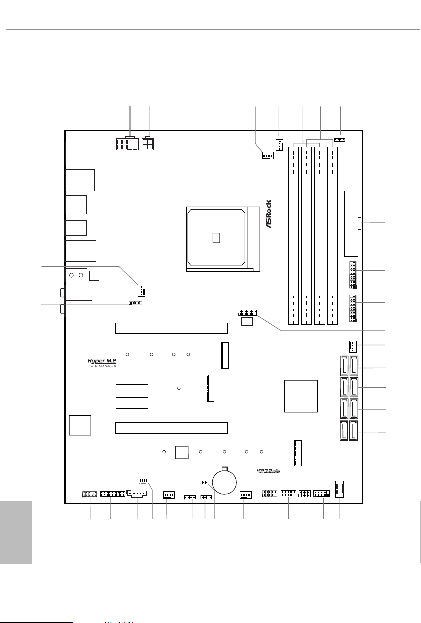
1.3 Motherboard Layout
English
8
Purity
Sound 4
TM
Page 15

No. Description
1 8 pin 12V Power Connector (ATX12V1)
2 4 pin 12V Power Connector (ATX12V2)
3 CPU Fan Connector (CPU_FAN1)
4 CPU / Waterpump Fan Connector (CPU_FAN2/WP)
5 2 x 288-pin DDR4 DIMM Slots (DDR4_A1, DDR4_B1)
6 2 x 288-pin DDR4 DIMM Slots (DDR4_A2, DDR4_B2)
7 AMD FAN LED Header (AMD_FAN_LED1)
8 ATX Power Connector (ATXPWR1)
9 USB 3.2 Gen1 Header (USB3_9_10)
10 USB 3.2 Gen1 Header (USB3_7_8)
11 SPI TPM Header (SPI_TPM_J1)
12 Chassis / Waterpump Fan Connector (CHA_FAN4/WP)
13 SATA3 Connectors (SATA3_1_2)
14 SATA3 Conne ctors (SATA3_3_4)
15 SATA3 Connectors (SATA3_5_6)
16 SATA3 Connectors (SATA3_7_8)
17 Front Panel Type C USB 3.2 Gen1 Header (F_USB31_TC_1)
18 System Panel Header (PANEL1)
19 Power LED and Speaker Header (SPK_PLED1)
20 USB 2.0 Header (USB_3_4)
21 USB 2.0 Header (USB_1_2)
22 Chassis/Water Pump Fan Connector (CHA_FAN3/WP)
23 Clear CMOS Jumper (CLRCMOS1)
24 Addressable LED Header (ADDR_LED1)
25 RGB LED Header (RGB_HEADER1)
26 Chassis / Waterpump Fan Connector (CHA_FAN2/WP)
27 Post Status Checker (PSC)
28 underbolt AIC Header (TB1)
29 TPM Header (TPMS1)
30 Front Panel Audio Header (HD_AUDIO1)
31 AMD LED Fan USB Header (USB_5)
32 Chassis / Waterpump Fan Connector (CHA_FAN1/WP)
X570 Extreme4
English
9
Page 16
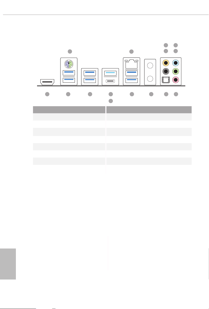
1.4 I/O Panel
5
1
2
436
13 10 9
No. Description No. Description
1 PS/2 Mouse/Keyboard Port 9 Antenna Bracket (on I/O Panel Shield)
2 LAN RJ-45 Port* 10 USB 3.2 Gen1 Ports (USB3_56)***
3 Central / Bass (Orange) 11 USB 3.2 Gen2 Type-A Port (USB31_TA_1)
4 Rear Speaker (Black) 12 USB 3.2 Gen2 Type-C Port (USB31_TC_1)
5 Line In (Light Blue) 13 USB 3.2 Gen1 Ports (USB3_34)
6 Front Speaker (Lime)** 14 USB 3.2 Gen1 Ports (USB3_12)
7 Microphone (Pink) 15 HDMI Port
8 Optical SPDIF Out Port
12
78111415
English
10
Page 17
X570 Extreme4
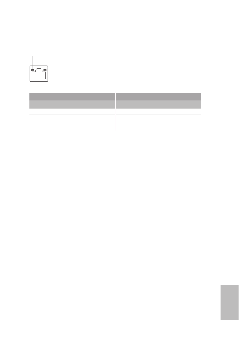
* ere are two LEDs on each LAN port. Please refer to the table below for the LAN port LED indications.
ACT/LINK LED
SPEED LED
LAN Por t
Activity / Link LED Speed LED
Status Description Status Description
O No Link O 10Mbps connection
Blinking Data Activity Orange 100Mbps connection
On Link Green 1Gbps connection
11
English
Page 18

** If you use a 2- channel speaker, plea se connect the speake r’s plug into “Front Spea ker Jack”. See the table below
for connection d etails in accordance w ith the type of speaker you use.
Audio Output
Channels
Front Speaker
(No. 6)
Rear Speaker
(No. 4)
Central / Bass
(No. 3)
2 V -- -- --
4 V V -- --
6 V V V --
8 V V V V
*** ACPI wake-up function is not supported on USB3_ 56 ports.
Line In
(No.5)
English
12
Page 19

X570 Extreme4
Chapter 2 Installation
is is an ATX form factor motherboard. Before you install the motherboard, study
the conguration of your chassis to ensure that the motherboard ts into it.
Pre-installation Precautions
Take note of the following precautions before you install motherboard components
or change any motherboard settings.
Make sure to unplug the power cord before installing or removing the motherboard.
•
Failure to do so may cause physical injuries to you and damages to motherboard
components.
In order to avoid damage from static electricity to the motherboard’s components,
•
NEVER place your motherboard directly on a carpet. Also remember to use a grounded
wrist strap or touch a safety grounded object before you handle the components.
Hold components by the edges and do not touch the ICs.
•
Whenever you uninstall any components, place them on a grounded anti-static pad or
•
in the bag that comes with the components.
When placing screws to secure the motherboard to the chassis, please do not over-
•
tighten the screws! Doing so may damage the motherboard.
13
English
Page 20
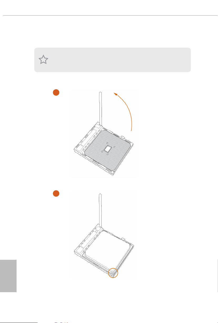
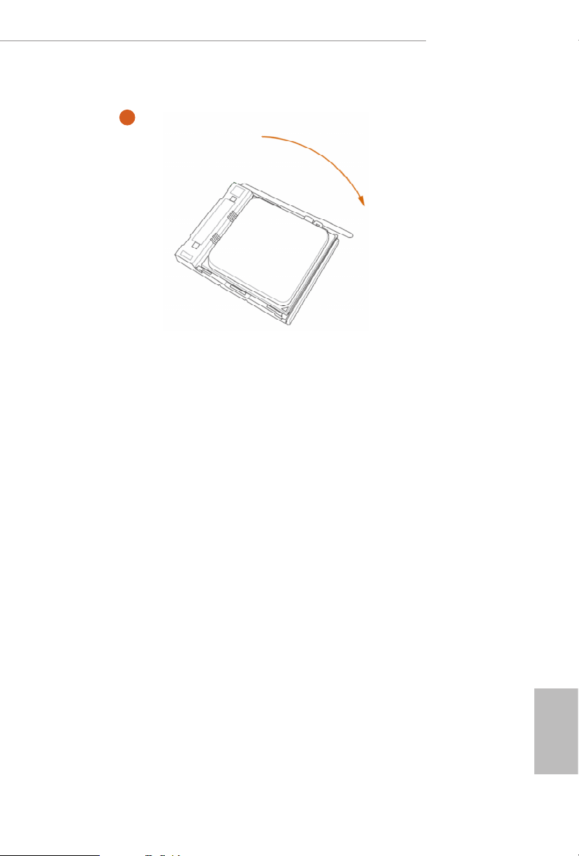
2.1 Installing the CPU
Unplug all power cables be fore installing the CPU.
1
English
14
2
Page 21
X570 Extreme4
3
15
English
Page 22
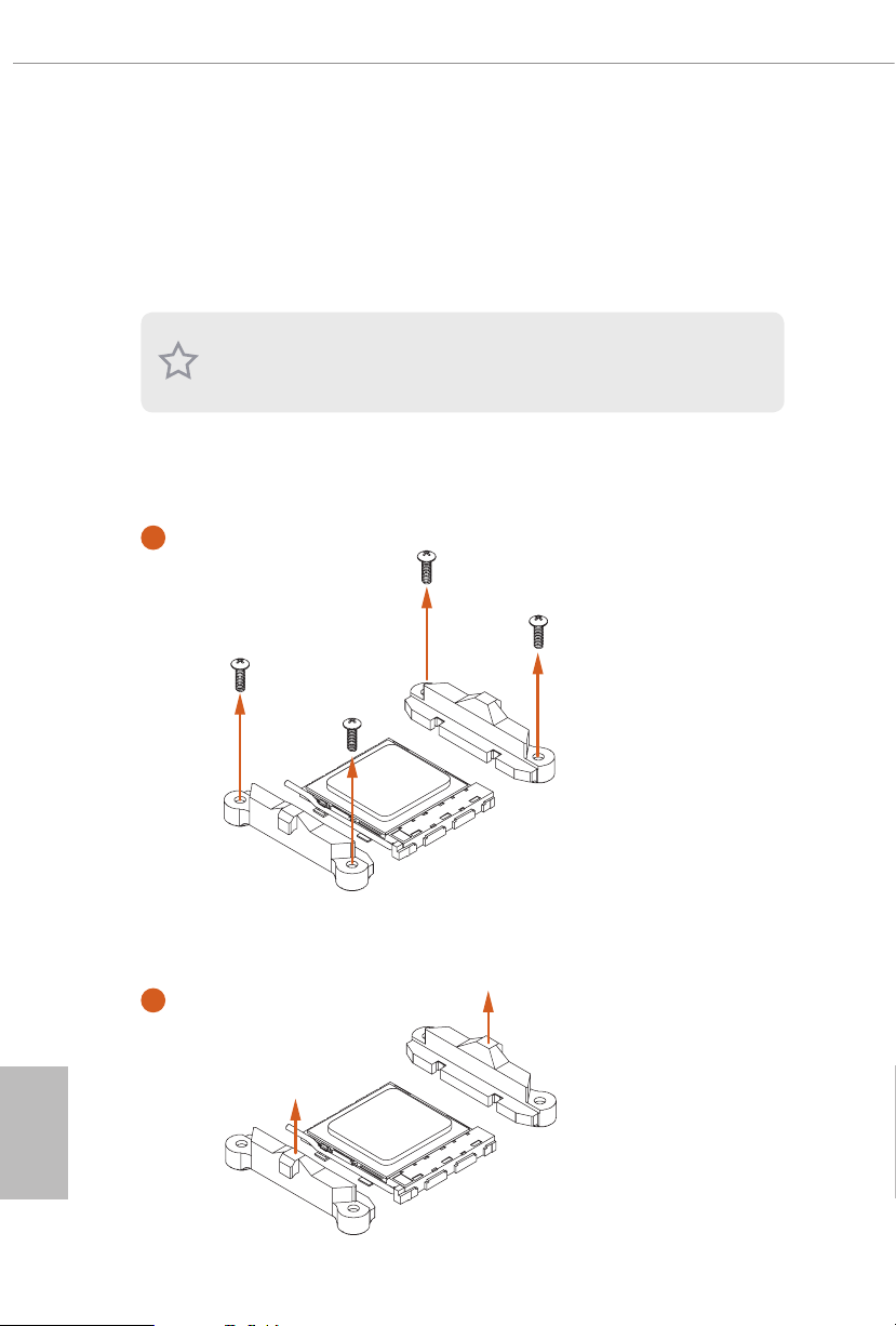
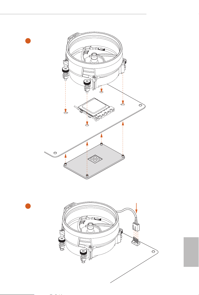
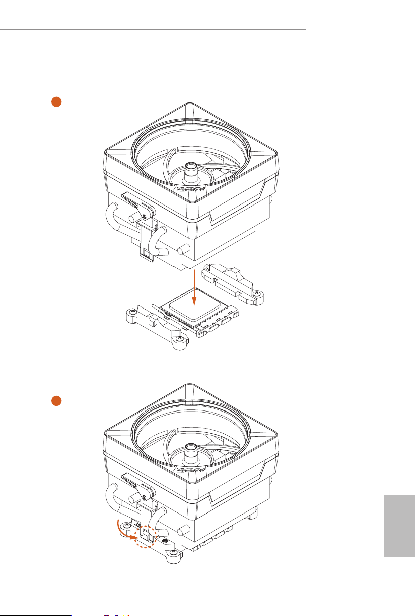
2.2 Installing the CPU Fan and Heatsink
Aer you install the CPU into this motherboard, it is necessary to install a larger
heatsink and cooling fan to dissipate heat. You also need to spray thermal grease
between the CPU and the heatsink to improve heat dissipation. Ma ke sure that the
CPU and the heatsink are securely fastened and in good contact with each other.
Please turn o the power or remove th e power cord before changing a CPU or heatsink.
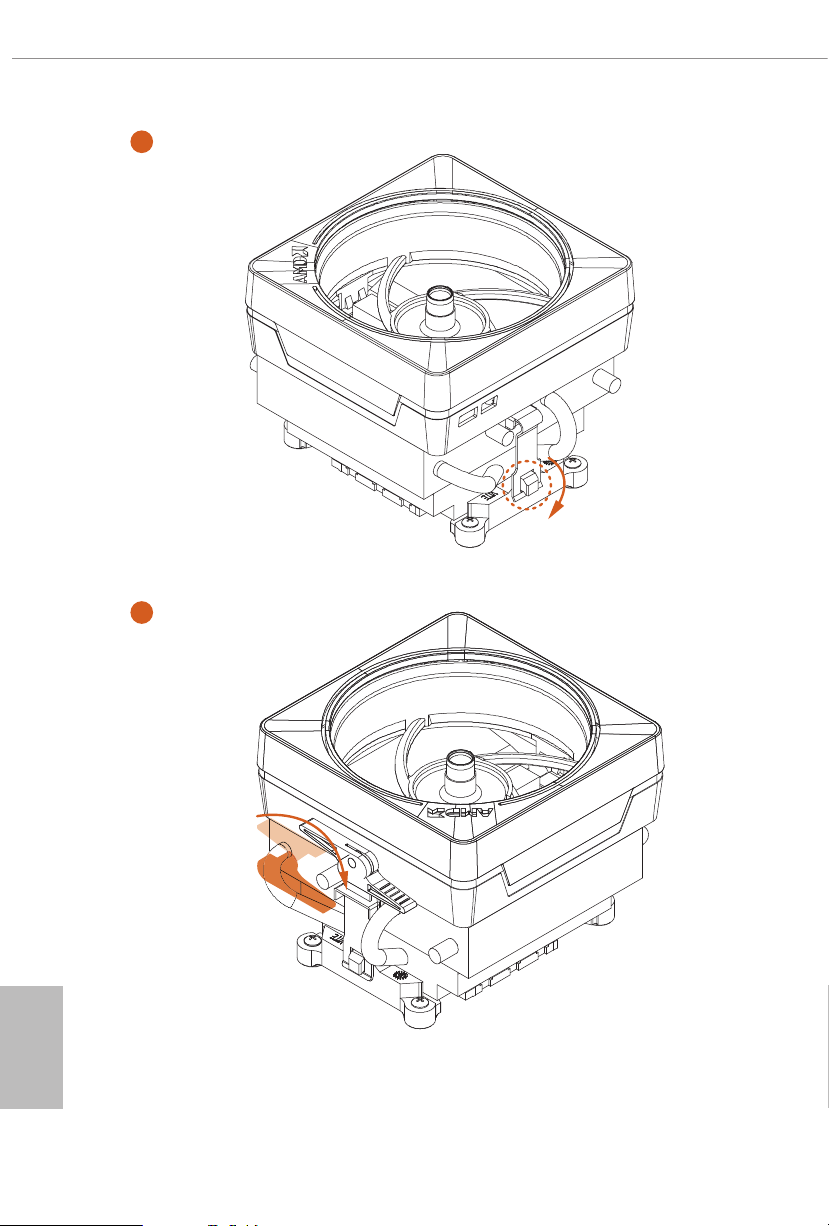
Installing the CPU Box Cooler SR1
1
English
16
2
Page 23
X570 Extreme4
3
4
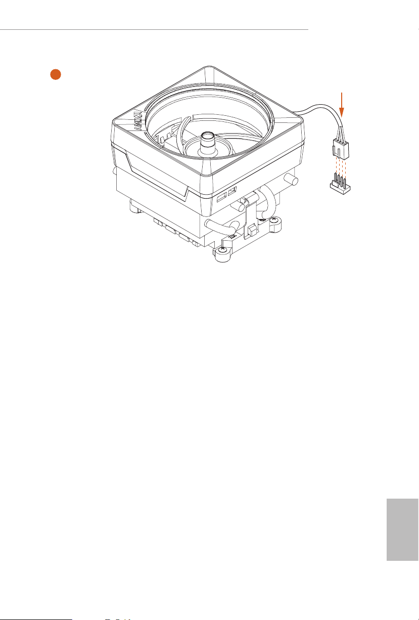
1
N
FA
_
U
P
C
English
17
Page 24
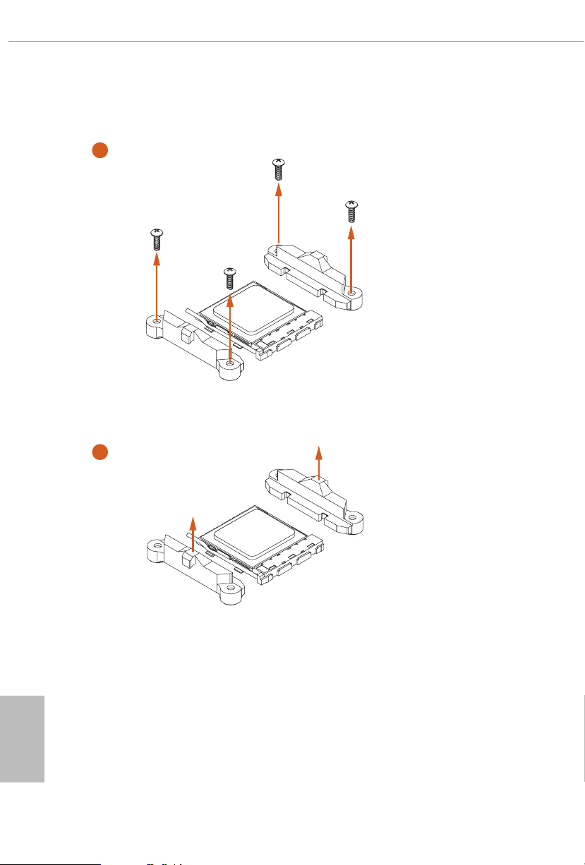
Installing the AM4 Box Cooler SR2
1
2
English
18
Page 25
X570 Extreme4
3
19
English
Page 26
4
1
N
FA
_
U
P
C
5
4-pin FAN cable
English
20
RGB LED Cable
1
N
FA
CPU_
1
D
E
L
_
N
FA
_
D
AM
+12V
*e diagrams shown here are for reference only. e headers might be in a dierent position on
your motherboard. Please refer to page 35 for the orientation of AMD Fan LED Header (AMD_
FAN_LED1).
Page 27
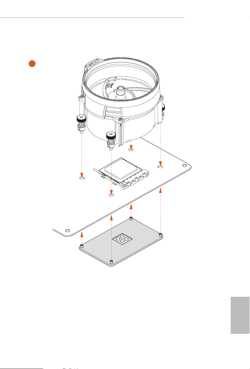
Installing the AM4 Box Cooler SR3
1
X570 Extreme4
2
English
21
Page 28
3
4
English
22
Page 29
X570 Extreme4
5
FAN1
CPU_
23
English
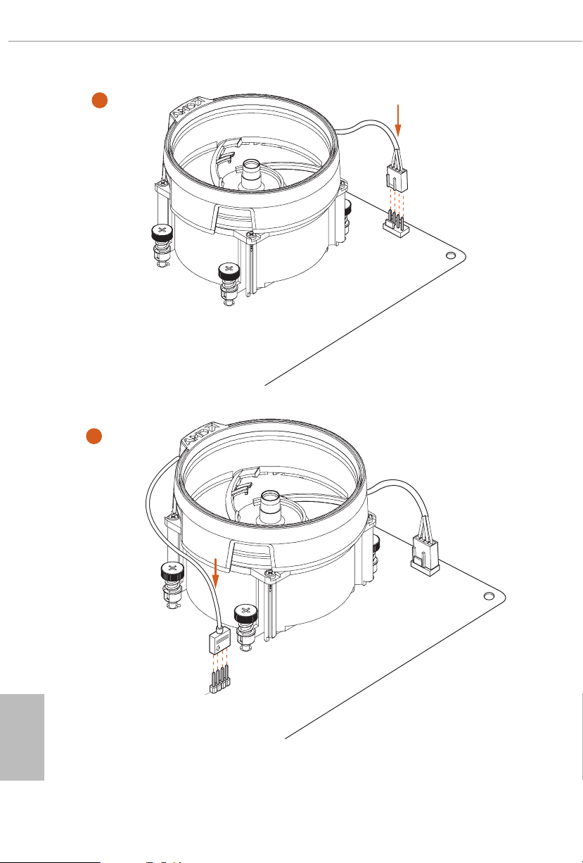
Page 30

6
1
N
FA
_
U
P
C
2
D
E
L
_
B
RG
+12V
or
7
1
N
FA
_
U
P
C
1
D
E
L
_
N
FA
_
D
AM
5
_
B
S
U
Please note that only one cable should be used at a time in this step.
English
If you select AMD_FAN_LED1, please install ASRock utility "ASRock Polychrome SYNC".
If you select USB connector, please install AMD utility "SR3 Settings Soware".
*e diagrams shown here are for reference only. e headers might be in a dierent position on your
motherboard. Please refer to page 35 for the orientation of AMD Fan LED Header (AMD_FAN_LED1)
and page 31 for the orientation of AMD LED Fan USB Header (USB_5).
24
Page 31

2.3 Installing Memory Modules (DIMM)
is motherboard provides four 288-pin DDR4 (Double Data Rate 4) DIMM slots,
and supports Dual Channel Memory Technology.
1. For dual channel cong uration , you always need to in stall identical (the same
brand, speed , size and chip-type) DDR4 DIMM pairs.
2. It is unable to activate Du al Channel Memory Technology with only one or three
memory module installed.
3. It is not allowed to install a DDR, DDR2 or DDR3 memory module into a DDR4
slot; otherwise, this motherboard and DIMM may be damaged.
4. We suggest that you install the memory modules on DDR4_A 2 and DDR4_B2 rst
for better DRAM compatibility on 2 DIMM s conguration.
AMD non-XMP Memory Frequency Support
Ryzen Series CPUs (Matisse):
X570 Extreme4
UDIMM Memory Slot
A1 A2 B1 B2
- SR - - 3200
- DR - - 3200
- SR - SR 3200
- DR - DR 3200
SR SR SR SR 2933
SR/DR DR SR/DR DR 2667
SR/DR SR/DR SR/DR SR/DR 2667
Frequency
(Mhz)
Ryzen Series CPUs (Pinnacle Ridge):
UDIMM Memory Slot
A1 A2 B1 B2
- SR - - 2933
- DR - - 2933
- SR - SR 2933
- DR - DR 2933
SR SR SR SR 2933
SR/DR DR SR/DR DR 2667
SR/DR SR/DR SR/DR SR/DR 2133-2400
Frequency
(Mhz)
English
25
Page 32

Ryzen Series CPUs (Picasso):
UDIMM/SO-DIMMs Memory Slot
# of DIMMs on
the Channel
1 of 1 xR
1 of 2 xR-0
2 of 2 1R-1R 2133
2 of 2 2R-xR 1866
x=1 or 2
SR: Single rank DIMM, 1Rx4 or 1R x8 on DIMM module label
DR: Dua l rank DIMM, 2Rx4 or 2R x8 on DIMM module label
# of Ranks
per DIMM
1.20V
SR: 2933
DR: 2677
SR: 2667
DR: 2400
English
26
Page 33

e DIMM only ts in one correct orie ntation. It will cause permanent dam age to
the motherboard and the DIMM if you force the DIMM into the slot at incor rect
orientation.
1
2
X570 Extreme4
3
English
27
Page 34

2.4 Expansion Slots (PCI Express Slots)
ere are 5 PCI Express slots on the motherboard.
Before installing an ex pansion card, please make sure that the power supply is switched o
or the power cord is unplug ged. Pl ease re ad the documentation of the expansion card and
make necessary hardware settings for the card before you start the installation.
PCIe slots:
PCIE1 (PCIe 4.0 x16 slot) is used for PCI Express x16 lane width graphics cards.
PCIE2 (PCIe 4.0 x1 slot) is used for PCI Express x1 lane width cards.
PCIE3 (PCIe 4.0 x1 slot) is used for PCI Express x1 lane width cards.
PCIE4 (PCIe 4.0 x16 slot) is used for PCI Express x4 lane width graphics cards.
PCIE5 (PCIe 4.0 x1 slot) is used for PCI Express x1 lane width cards.
PCIe Slot Congurations
PCIE1 PCIE4
Ryzen Series CPUs (Matisse) Gen4x16 Gen4x4
Ryzen Series CPUs (Pinnacle Ridge) Gen3x16 Gen3x4
English
28
Ryzen Series CPUs (Picasso) Gen3x8 Gen3x4
For a better ther mal environme nt, ple ase connect a ch assis fan to the motherboard’s
chassis fan connector (CHA_ FAN1/WP, CHA_ FAN2/WP , CHA_FAN3/WP or
CHA_ FAN4/WP ) when using multiple graphics cards.
Page 35

X570 Extreme4
2.5 Jumpers Setup
e illustration shows how jumpers are setup. When the jumper cap is placed on
the pins, the jumper is “Short”. If no jumper cap is placed on the pins, the jumper is
“O pen”.
Clear CMOS Jumper
(CLRCMO S1)
(see p.8, No. 23)
CLRCMOS1 allows you to clear the data in CMOS. e data in CMOS includes
system setup information such as system password, date, time, and system setup
parameters. To clear and reset the system parameters to default setup, please
turn o the computer and unplug the power cord, then use a jumper cap to short
the pins on CLRCMOS1 for 3 seconds. Please remember to remove the jumper
cap aer clearing the CMOS. If you need to clear the CMOS when you just nish
updating the BIOS, you must boot up the system rst, and then shut it down
before you do the clear-CMOS action.
2-pin Jumper
Short: Clear CMOS
Open: Default
29
English
Page 36

2.6 Onboard Headers and Connectors
1
Onboard headers and connectors are NOT jump ers. Do NOT place jumper caps over these
heade rs and connectors. Placing jumper caps over the headers and connectors will cause
permanent damage to the motherboard.
System Panel Header
(9-pi n PANEL1)
(see p.8, No. 18)
PWRBTN (Power Button):
Connec t to the power button on the ch assi s front panel. You may congure the way to tur n
o your system using the power button.
RESET (Reset B utton):
Connec t to the reset button on the ch assi s front panel. P ress the reset button to re start the
computer if the computer f reezes and fails to per form a normal restar t.
PLED (Syste m Power LED):
Connec t to the power status indicator on the chas sis front panel. e LED i s on when the
system is operating. e LED keeps blinking when the system is in S1/S3 sleep state. e
LED is o when the system is in S4 slee p state or powered o (S5).
HDLED (Ha rd Drive Activity LED):
Connec t to the hard drive ac tivity LED on the chassis front panel. e LED is on when the
hard drive is reading or wr iting data.
e front panel de sign may dier by chassis. A front panel module mainly consists of powe r
button, reset button , power LED, hard dr ive activity LED, speaker and etc. When connecting your ch assi s front panel module to thi s header, make sure the wire a ssignments and the
pin assignments are matched correctly.
PLED+
PLED-
HDLED-
HDLED+
PWRBTN#
GND
RESET#
GND
GND
Connect the power
button, reset button and
system status indicator on
the chassis to this header
according to the pin
assignments below. Note
the positive and negative
pins before connecting
the cables.
English
30
Page 37

X570 Extreme4
1
+5V
DUMMY
PLED+
PLED+
PLED-
DUMMY
SPEAKER
DUMMY
GND
GND
P+
P-
USB_PWR
P+
P-
USB_PWR
1
1
1
Power LED and Speaker
Header
(7-pin SPK_PLED1)
(see p.8, No. 19)
Serial ATA3 Connectors
(SATA3_1_2:
see p.8, No. 13)
(SATA3_3_4:
see p.8, No. 14)
(SATA3_ 5_6:
see p.8, No. 15)
(SATA3_ 7_ 8:
see p.8, No. 16)
AMD LED Fan USB
Header
(4-pin USB_5)
(see p.8, No. 31)
SATA3_2
SATA3_4
SATA3_6
SATA3_8
P-
USB_PWR
Please connect the
chassis power LED and
the chassis speaker to this
header.
ese eight SATA3
connectors support SATA
SATA3_1
data cables for internal
storage devices with up to
6.0 Gb/s data transfer rate.
SATA3_3
SATA3_5
SATA3_7
is header is used for
GND
P+
connecting the USB
connector on the AMD
SR3 Heatsink.
USB 2.0 Headers
(9-pin USB_1_2)
(see p.8, No. 21)
(9-pin USB_3_4)
(see p.8, No. 20)
USB 3.2 Gen1 Headers
(19-pin USB3_7_8)
(see p.8, No. 10)
(19-pin USB3_9_10)
(see p.8, No. 9)
Vbus
IntA_PA_SSRX-
IntA_PA_SSRX+
IntA_PA_SSTX-
IntA_PA_SSTX+
IntA_PA_D-
IntA_PA_D+
ere are two headers
on this motherboard.
Each USB 2.0 header can
support two ports.
VbusVbus
IntA_PB_SSRX-
IntA_PB_SSRX+
GND
IntA_PB_SSTX-
GND
IntA_PB_SSTX+
GND
IntA_PB_D-
GND
IntA_PB_D+
Dummy
ere are two headers on
this motherboard. Each
USB 3.2 Gen1 header can
support two ports.
English
31
Page 38

Front Panel Type C USB
J_SENSE
OUT2_L
1
MIC_RET
PRESENCE#
GND
OUT2_R
MIC2_R
MIC2_L
OUT_RET
ype-C Cable
FAN_SPEED_CONTROL
4
GND
1 2 3 4
3.2 Gen1 Header
(26-pin F_USB31_TC_1)
(see p.8, No. 17)
USB T
ere is one Front
Panel Type C USB 3.2
Gen1 Header on this
motherboard. is header
is used for connecting a
USB 3.2 Gen1 module for
additional USB 3.2 Gen1
ports.
English
32
Front Panel Audio Header
(9-pin HD_ AUDIO1)
(see p.8, No. 30)
1. High Denition Audio support s Jack Sensing, but the panel wire on the cha ssis must sup port HDA to function correctly. Ple ase fol low the instructions in our manual and chassis
manual to install your system.
2. If you use an AC’97 audio panel , please install it to th e front panel audio header by the
steps below:
A. Connect Mic_IN (MIC) to MIC2_ L.
B. Conne ct Audio_R (RIN) to OUT2_R and Audio_ L (LIN) to OUT2_ L.
C. Connect Ground (GND) to Ground (GND).
D. MIC_ RET and OUT_RET are for the HD audio panel only. You don’t ne ed to conn ect
them for the AC’97 audio panel .
E. To activate the front mic, go to the “FrontMic” Tab in the Realtek Control panel and
adjust “Recording Volume”.
Chassis Water Pump Fan
Connectors
(4-pin CHA_FAN1/WP)
CHA_FAN_SPEED
FAN_VOLTAGE
GND
(see p.8, No. 32)
is header is for
connecting audio devices
to the front audio panel.
is motherboard
3
provides four 4-Pin water
2
1
cooling
connectors. If you plan to
connect a 3-Pin
(4-pin CHA_FAN2/WP)
(see p.8, No. 26)
FAN_VOLTAGE
FAN_SPEED
FAN_SPEED_CONTROL
water cooler fan, please
connect it to Pin 1-3.
(4-pin CHA_FAN3/WP)
(see p.8, No. 22)
chassis
fan
chassis
Page 39

X570 Extreme4
FAN_SPEED_CONTROL
1 2 3 4
4
1
8 5
GND
OL
1
FAN_SPEED_CONTROL
4
(4-pin CHA_FAN4/WP)
(see p.8, No. 12)
CPU Fan Connector
(4-pin CPU_FAN1)
(see p.8, No. 3)
CPU Water Pump Fan
Connector
(4-pin CPU_FAN2/WP)
(see p.8, No. 4)
ATX Power Connector
(24-p i n ATX PWR1)
(see p.8, No. 8)
2
3
4
CPU_FAN_SPEED
FAN_VOLTAGE
FAN_VOLTAGE
12
1
FAN_VOLTAGE
CHA_FAN_SPEED
FAN_SPEED_CONTR
GND
FAN_SPEED
GND
24
13
is motherboard pro-
vides a 4-Pin CPU fan
(Quiet Fan) connector.
If you plan to connect a
3-Pin CPU fan, please
connect it to Pin 1-3.
is motherboard
3
provides a 4-Pin water
2
1
cooling CPU fan
connector. If you plan
to connect a 3-Pin CPU
water cooler fan, please
connect it to Pin 1-3.
is motherboard pro-
vides a 24-pin ATX power
connector. To use a 20-pin
ATX power supply, please
plug it along Pin 1 and Pin
13.
ATX 12V Power
Connector
(8-pin ATX12V1)
(see p.8, No. 1)
is motherboard pro-
vides an 8-pin ATX 12V
power connector. To use a
4-pin ATX power supply,
please plug it along Pin 1
and Pin 5.
*Warning: Please make
sure that the power cable
connected is for the CPU
and not the graphics
card. Do not plug the
PCIe power cable to this
connector.
English
33
Page 40

ATX 12V Power
1
1
SPI_DQ3
#
Connector
(4-pin ATX12V2)
(see p.8, No. 2)
Please connect an ATX
12V power supply to this
connector.
*e power supply plug
ts into this connector in
only one orientation.
English
underbolt AIC
Connector
(5-p i n TB1)
(see p.8, No. 28)
LPC/TPM Header
(17-pi n TP MS1)
(see p.8, No. 29)
SPI TPM Header
(13 -pi n SPI_T PM _J1)
(see p.8, No. 11)
1
GN D
PC ICL K
+3.3V
SPI_CS0
SPI_DQ2
SMB _CL K_M AIN
SMB _DA TA_ MAI N
FRA M E
PC IRS T #
Dummy
CLK
RSMRST#
SPI_MISO
LAD 2
LAD 1
+3 V
LAD 3
SPI_MOSI
RST#
SPI_TPM_CS
GND
GN D
S_P WRD WN #
LAD 0
TPM_PIRQ
Please connect a underbolt™
add-in card (AIC) to the
underbolt AIC connector via
the GPIO cable.
*Please install the underbolt™
AIC card to PCIE4 (default
slot).
*For the further information,
please visit ww w.asrock.com.
is connector supports Trusted
Platform Module (TPM) system,
which can securely store keys,
D
SER IRQ #
GN
digital certicates, passwords,
and data. A TPM system also
helps enhance network security,
GN D
+3V S B
protects digital identities, and
ensures platform integrity.
is connector supports SPI
Trusted Platform Module (TPM)
system, which can securely store
keys, digital certicates, pass-
words, and data. A TPM system
also helps enhance network
security, protects digital
identities, and ensures platform
integrity.
34
Page 41

X570 Extreme4
1
1
1
AMD FAN LED Header
(4- pi n AM D_FA N_
LED1)
(see p.8, No. 7)
RGB LED Header
(4-pi n RGB _HEA DER1)
(see p.8, No. 25)
12VGRB
12V GRB
AMD FAN LED Header is used
to connect RGB LED
extension cable that comes with
AMD heatsink. e cable
connection allows users to choose
from various LED lighting
eects.
*e AMD Fan LED Header is
compatible with a regular RGB
LED stripe.
Caution: Never install the FAN
LED cable in the wrong orienta-
tion; otherwise, the cable may
be damaged.
is RGB header is used to
connect RGB LED extension
cable which allows
users to choose from various LED
lighting eects.
Caution: Never install the RGB
LED cable in the wrong orienta-
tion; otherwise, the cable may
be damaged.
*Please refer to page 65 for
further instructions on this
header.
Addressable LED Header
(3-pin A DDR_LE D1)
(see p.8, No. 24)
VOUT
DO_ADDR
GND
is header is used to connect
Addressable
LED extension cable
which allows users to choose
from various LED lighting
eects.
Caution: Never install the
Addressable LED cable in the
wrong orientation; otherwise,
the cable may be damaged.
*Please refer to page 66 for
English
further instructions on this
header.
35
Page 42

2.7 Post Status Checker
Post Status Checker (PSC) diagnoses the computer when users power on the
machine. It emits a red light to indicate whether the CPU, memory, VGA or stor-
age is dysfunctional. e lights go o if the four mentioned above are functioning
normally.
English
36
Page 43

2.8 CrossFireXTM and Quad CrossFireXTM Operation Guide
is motherboard supports CrossFireXTM and Quad CrossFireXTM that allows you
to install up to two identical PCI Express x16 graphics cards.
1. You should only use identical CrossFireXTM-ready g raphics cards that are AM D certied.
2. Make sure that your graphics card driver supports A MD CrossFireXTM technology.
Download the drivers from the A MD’s website: www.amd.com
3. Make sure that your power supply unit (PSU) can provide at lea st the minimum power
your system requires. It is recommended to use a AMD certied PSU. Ple ase refer to the
AMD’s website for de tails.
4. If you pair a 12-pipe CrossFireXTM Edition card with a 16-pipe card, both cards will operate as 12-pipe card s while in CrossFireXTM mode.
5. Dierent CrossFireXTM cards may require dierent method s to enable CrossFireXTM.
Please refer to A MD graphics card manuals for de tailed installation guide.
2.8.1 Installing Two CrossFireXTM-Ready Graphics Cards
X570 Extreme4
CrossFire Bridge
Step 1
Insert one graphics card into PCIE1 slot
and the other graphics card to PCIE4 slot.
Make sure that the cards are properly
seated on the slots.
Step 2
Connect two graphics cards by installing
a CrossFire Bridge on the CrossFire Bridge
Interconnects on the top of the graphics
cards. (e CrossFire Bridge is provided
with the graphics card you purchase, not
bundled with this motherboard. Please
refer to your graphics card vendor for
deta ils .)
English
37
Page 44

Step 3
Connect a VGA cable or a DVI cable to the
monitor connector or the DVI connec-
tor of the graphics card that is inserted to
PCIE1 slot.
English
38
Page 45

2.8.2 Driver Installation and Setup
Step 1
Power on your computer and boot into OS.
Step 2
Remove the AMD drivers if you have any VGA drivers installed in your system.
e Catalyst Unins talle r is an optional do wnload. We recommend us ing this utility to uninstall any previously installed Catalyst drivers prior to installation. Plea se check AMD’s
website for AMD driver updates .
Step 3
Install the required drivers and CATALYST Control Center then restart your
computer. Please check AMD’s website for details.
Step 4
Double-click the AMD Catalyst Control
AMD Catalyst Control Center
Center icon in the Windows® sy stem tray.
X570 Extreme4
Step 5
In the le pane, click Performance and
then AMD CrossFireXTM. en select
Enable AMD CrossFireX and click Apply.
Select the GPU number according to your
graphics card and click Apply.
English
39
Page 46

2.9 M.2 WiFi/BT Module Installation Guide
e M.2 Socket (Key E) supports type 2230 WiFi/BT module.
Installing the WiFi/BT module
Step 1
Prepare a type 2230 WiFi/BT module
and the screw.
Step 2
Find the nut location to be used.
PCB Length: 3cm
Module Type: Type2230
A
English
40
Step 3
Align and gently insert the WiFi/BT
module into the M.2 slot. Please be
aware that the module only ts in one
orientation.
A
20
o
A
Page 47

X570 Extreme4
Step 4
Tighten the screw with a screwdriver
to secure the module into place.
Please do not overtighten the screw as
this might damage the module.
A
41
English
Page 48

2.10 M.2_SSD (NGFF) Module Installation Guide (M2_1)
4
e M.2, also known as the Next Generation Form Factor (NGFF), is a small size and
versatile card edge connector that aims to replace mPCIe and mSATA. e M.2 Socket
(M2_1) supports M Key ty pe 2230/2242/2260/2280 M.2 PCI Express module up to Gen4x4
(64 Gb/s) (with Matisse) or Gen3x4 (32 Gb/s) (with Pinnacle Ridge and Picasso).
Installing the M.2_SSD (NGFF) Module
Step 1
Prepare a M.2_SSD (NGFF) module
and the screw.
Step 2
English
3
Depending on the PCB type and
length of your M.2_SSD (NGFF)
module, nd the corresponding nut
location to be used.
2
1
A
BCD
No. 1 2 3 4
Nut Location A B C D
PCB Length 3cm 4.2cm 6cm 8cm
Module Type Type223 0 Ty pe 224 2 Type2 260 Ty pe 2280
42
Page 49

X570 Extreme4
1
Step 3
Before installing a M.2 (NGFF) SSD
2
module, please loosen the screws to
remove the M.2 heatsink.
1
*Please remove the protective lms on
the bottom side of the M.2 heatsink
before you install a M.2 SSD module.
1
Step 4
Prepare the M.2 stando that comes
with the package. en hand tighten
the stando into the desired nut
ABCD
location on the motherboard. Align
and gently insert the M.2 (NGFF)
SSD module into the M.2 slot. Please
be aware that the M.2 (NGFF) SSD
module only ts in one orientation.
o
ABCD
20
Step 5
Tighten the screw with a screwdriver
to secure the module into place.
Please do not overtighten the screw as
NUT1NUT2D
this might damage the module.
English
43
Page 50

M.2_SSD (NGFF) Module Support List
Vendor Interface P/N
SanDisk PCIe SanDisk-SD6PP4M-128G( Gen2 x2)
Intel PCIe INTEL 6000P-SSDPEKKF256G7 (nvme)
Intel PCIe INTEL 6000P-SSDPEKKF512G7 (nvme)
Intel PCIe SSDPEKKF512G7 NVME / 512GB
Kingston PCIe Kingston SHPM2280P2 / 240G (Gen2 x4)
Samsung PCIe Samsung XP941-MZHPU512HCGL(Gen2x4)
Samsung PCIe SM951 (NVME) / 512GB
Samsung PCIe SM951 (M ZHPV512HDGL) / 512GB
ADATA PCIe ASX8000NP-512GM-C / 512GB
ADATA PCIe ASX7000NP-512GT-C / 512GB
Kingston PCIe SKC1000/480G
Kingston PCIe SKC1000/960GB NVME
PLEXTOR PCIe PX-512M8Pe G/ 512GB
WD PCIe W DS512G1X0 C-0 0ENX0 (NV ME) / 512GB
For the latest updates of M.2_SSD (NFGG) module support list, please visit our website
for details: http://www.asrock.com
English
44
Page 51

X570 Extreme4
5
2.11 M.2_SSD (NGFF) Module Installation Guide (M2_2)
e M.2, also known as the Next Generation Form Factor (NGFF), is a small size and
versatile card edge connector that aims to replace mPCIe and mSATA. e Hyper M.2
Socket (M2_2) supports M Key ty pe 2230/2242/2260/2280/22110 M.2 SATA3 6.0 Gb/s
module and M.2 PCI Express module up to Gen4x4 (64 Gb/s).
Installing the M.2_SSD (NGFF) Module
Step 1
Prepare a M.2_SSD (NGFF) module
and the screw.
4
3
Depending on the PCB type and
length of your M.2_SSD (NGFF)
module, nd the corresponding nut
Step 2
2
1
A
BCDE
location to be used.
No. 1 2 3 4 5
Nut Location A B C D E
PCB Length 3cm 4.2cm 6cm 8cm 11cm
Module Type Type223 0 Ty pe 224 2 Type2 260 Ty pe 2280 Type 22110
English
45
Page 52

1
Step 3
Before installing a M.2 (NGFF) SSD
2
module, please loosen the screws to
remove the M.2 heatsink.
1
*Please remove the protective lms on
the bottom side of the M.2 heatsink
before you install a M.2 SSD module.
1
*Please remove the protective lms on
the bottom side of the M.2 heatsink
before you install a M.2 SSD module.
Step 4
Prepare the M.2 stando that comes
with the package. en hand tighten
the stando into the desired nut
ABCDE
location on the motherboard. Align
and gently insert the M.2 (NGFF)
SSD module into the M.2 slot. Please
be aware that the M.2 (NGFF) SSD
module only ts in one orientation.
English
46
o
ABCDE
20
Step 5
Tighten the screw with a screwdriver
to secure the module into place.
NUT1NUT2DE
Please do not overtighten the screw as
this might damage the module.
Page 53

M.2_SSD (NGFF) Module Support List
Vendor Interface P/N
SanDisk PCIe SanDisk-SD6PP4M-128G( Gen2 x2)
Intel PCIe INTEL 6000P-SSDPEKKF256G7 (nvme)
Intel PCIe INTEL 6000P-SSDPEKKF512G7 (nvme)
Intel PCIe SSDPEKKF512G7 NVME / 512GB
Intel SATA 540S-SSDSCKKW240H6 / 240GB
Kingston PCIe Kingston SHPM2280P2 / 240G (Gen2 x4)
Samsung PCIe Samsung XP941-MZHPU512HCGL(Gen2x4)
Samsung PCIe SM951 (NVME) / 512GB
Samsung PCIe SM951 (M ZHPV512HDGL) / 512GB
ADATA SATA ADATA - AXNS381E-128GM-B
ADATA PCIe ASX8000NP-512GM-C / 512GB
ADATA PCIe ASX7000NP-512GT-C / 512GB
ADATA SATA ASU800NS38-512GT-C / 512GB
Crucial SATA Crucial-CT240M500SSD4-240GB
ezlink SATA ezlink P51B-80-120GB
Intel SATA INTEL 540S-SSDSCKKW240H6-240GB
Kingston SATA Kingston SM2280S3G2/120G - Win8.1
Kingston SATA Kingston-RBU-SNS8400S3 / 180GD
Kingston PCIe SKC1000/480G
Kingston PCIe SKC1000/960GB NVME
LITEON SATA LIT EON LJ H-256 V2G-256GB (2260)
PLEXTOR SATA PLEXTOR PX-128M6G-2260-128GB
PLEXTOR SATA PLEXTOR PX-128M7VG-128GB
PLEXTOR PCIe PX-512M8Pe G/ 512GB
SanDisk SATA SanDisk X400-SD8SN8U-128G
SanDisk SATA Sandisk Z400s-SD8SNAT-128G-1122
SanDisk SATA SanDisk-SD6SN1M-128G
Tra nscend SATA Transcend TS256GMTS800-256GB
Tra nscend SATA TS512GMTS800 / 512GB
V-Col or SATA V- Colo r 12 0 G
V-Col or SATA V- Colo r 24 0G
WD SATA WD GREEN WDS240G1G0B-00RC30
WD PCIe W DS512G1X0 C-0 0ENX0 (NV ME) / 512GB
X570 Extreme4
For the latest updates of M.2_SSD (NFGG) module support list, please visit our website
for details: http://www.asrock.com
English
47
Page 54

Chapter 3 Software and Utilities Operation
3.1 Installing Drivers
e Support CD that comes with the motherboard contains necessary drivers and
useful utilities that enhance the motherboard’s features.
Running The Support CD
To begin using the support CD, insert the CD into your CD-ROM drive. e CD
automatically displays the Main Menu if “AUTORUN” is enabled in your computer.
If the Main Menu does not appear automatically, locate and double click on the le
“ASRSETUP.EXE” in the Support CD to display the menu.
Drivers Menu
e drivers compatible to your system will be auto-detected and listed on the
support CD driver page. Please click Install All or follow the order from top to
bottom to install those required drivers. erefore, the drivers you install can work
properly.
Utilities Menu
e Utilities Menu shows the application soware that the motherboard supports.
Click on a specic item then follow the installation wizard to install it.
English
48
Page 55

3.2 A-Tuning
A-Tuning is ASRock’s multi purpose soware suite with a new interface, more new
features and improved utilities.
3.2.1 Installing A-Tuning
A-Tu ni n g can be downloaded from ASRock Live Update & APP Shop. Aer the
installation, you will nd the icon “A-Tu n i ng“ on your desktop. Double-click the
“A-Tu ni n g“ icon, A-Tu n i n g main menu will pop up.
3.2.2 Using A-Tuning
ere are ve sections in A-Tuning main menu: Operation Mode, OC Tweaker,
System Info, FAN-Tastic Tuning and Settings.
Operation Mode
Choose an operation mode for your computer.
X570 Extreme4
49
English
Page 56

OC Tw eaker
Congurations for overclocking the system.
System Info
View information about the system.
*e System Browser tab may not appear for certain models.
English
50
Page 57

X570 Extreme4
FAN-Tastic Tuning
Congure up to ve dierent fan speeds using the graph. e fans will automatically shi
to the next speed level when the assigned temperature is met.
Settings
Congure ASRock A-Tuning. Click to select "Auto run at Windows Startup" if you
want A-Tuning to be launched when you start up the Windows operating system.
English
51
Page 58

3.3 ASRock Live Update & APP Shop
e ASRock Live Update & APP Shop is an online store for purchasing and
downloading soware applications for your ASRock computer. You can quickly and
easily install various apps and support utilities. With ASRock Live Update & APP
Shop, you can optimize your system and keep your motherboard up to date simply
with a few clicks.
Double-click on your desktop to access ASRock Live Update & APP Shop
utility.
*You need to be connected to the Internet to download apps f rom the ASRock Live Update & APP Shop.
3.3.1 UI Overview
English
Category Panel
Information Panel
Category Panel: e category panel contains several category tabs or buttons that
when selected the information panel below displays the relative information.
Information Panel: e information panel in the center displays data about the
currently selected category and allows users to perform job-related tasks.
Hot News: e hot news section displays the various latest news. Click on the image
to visit the website of the selected news and know more.
Hot News
52
Page 59

X570 Extreme4
3.3.2 Apps
When the "Apps" tab is selected, you will see all the available apps on screen for you
to download.
Installing an App
Step 1
Find the app you want to install.
e most recommended app appears on the le side of the screen. e other various
apps are shown on the right. Please scroll up and down to see more apps listed.
You can check the price of the app and whether you have already intalled it or not.
- e red icon displays the price or "Free" if the app is free of charge.
- e green "Installed" icon means the app is installed on your computer.
Step 2
Click on the app icon to see more details about the selected app.
English
53
Page 60

Step 3
If you want to install the app, click on the red icon to start downloading.
Step 4
When installation completes, you can nd the green "Installed " icon appears on the
upper right corner.
English
54
To uninstall it, simply click on the trash can icon .
*e trash icon may not appear for certain apps.
Page 61

Upgrading an App
You can only upgrade the apps you have already installed. When there is an
available new version for your app, you will nd the mark of "New Version"
appears below the installed app icon.
Step 1
Click on the app icon to see more details.
X570 Extreme4
Step 2
Click on the yellow icon to start upgrading.
English
55
Page 62

3.3.3 BIOS & Drivers
Installing BIOS or Drivers
When the "BIOS & Drivers" tab is selected, you will see a list of recommended or
critical updates for the BIOS or drivers. Please update them all soon.
Step 1
Please check the item information before update. Click on to see more details.
Step 2
English
56
Click to select one or more items you want to update.
Step 3
Click Update to start the update process.
Page 63

3.3.4 Setting
In the "Setting" page, you can change the language, select the server location, and
determine if you want to automatically run the ASRock Live Update & APP Shop
on Windows startup.
X570 Extreme4
57
English
Page 64

3.4 ASRock Polychrome SYNC
1
ASRock Polychrome SYNC is a lighting control utility specically designed for unique indi-
viduals with sophisticated tastes to build their own stylish colorful lighting system. Simply by
connecting the LED strip, you can customize various lighting schemes and patterns, including
Static, Breathing, Strobe, Cycling, Music, Wave and more.
Connecting the LED Strip
Connect your RGB LED strip to the
RGB LED Header (RGB_HEADE R1)
on the motherboard.
English
X570
EXTRE ME4
1
B
R
G
V
2
1
RGB_HEADER1
12V GRB
1. Never install the RGB LED cable in the wrong orientation; othe rwise, the cable may be
damaged.
2. Be fore installing or remov ing your RGB LED cable, please power o your system an d
unplug the power cord from the power supply. Failure to do so may c ause damages to
motherboard components.
1. Please note that the RGB LED strips do not come with the package.
2. e RGB LED header supports standard 5050 RGB LED strip (12V/G/R/B), with a
maximum power rating of 3A (12V) and length within 2 meters.
58
Page 65

Connecting the Addressable RGB LED Strip
D
1
Connect your
the motherboard.
Addressable RGB LED
X570
EXTR EME4
strip to the
Addressable LED Header (ADDR_ LED1)
1
1. Never install the RGB LED cable in the wrong orientation; othe rwise, the cable may be
damaged.
2. Be fore installing or remov ing your RGB LED cable, please power o your system an d
unplug the power cord from the power supply. Failure to do so may c ause damages to
motherboard components.
ADDR_LED1
GN
DO_ADDR
VOUT
X570 Extreme4
on
1. Please note that the RGB LED strips do not come with the package.
2. e RGB LED header supports WS2812B addressable RGB LED strip (5V/Data/
GND), with a ma ximum power rating of 3A (5V) and length within 2 meters.
English
59
Page 66

ASRock Polychrome SYNC Utility
Now you can adjust the RGB LED color through the ASRock RGB LED utility. Download
this utility from the ASRock Live Update & APP Shop and start coloring your PC style
your way!
Drag the tab to customize your
preference.
Toggle on/o the
RGB LED switch
Sync RGB LED eects
for all LED regions of
the motherboard
Select a RGB LED light eect
from the drop-down menu.
English
60
Page 67

X570 Extreme4
Chapter 4 UEFI SETUP UTILITY
4.1 Introduction
is section explains how to use the UEFI SETUP UTILITY to congure your
system. You may run the UEFI SETUP UTILITY by pressing <F2> or <Del> right
aer you power on the computer, other wise, the Power-On-Self-Test (POST) will
continue with its test routines. If you wish to enter the UEFI SETUP UTILITY aer
POST, restart the system by pressing <Ctl> + <Alt> + <Delete>, or by pressing the
reset button on the system chassis. You may also restart by turning the system o
and then back on.
Becau se the UEFI soware is constantly being upd ated, the following UEFI setup
screens and de scriptions are for refe rence purpose only, and they may not exactly
match what you see on your scre en.
4.1.1 UEFI Menu Bar
e top of the screen has a menu bar with the following selections:
Main
OC Tweaker
Advanced
Tool
H/W Monitor
Security
Boot
Exit
For setting system time/date information
For overclocking congurations
For advanced system congurations
Useful tools
Displays current hardware status
For security settings
For conguring boot settings and boot priority
Exit the current screen or the UEFI Setup Utility
English
61
Page 68

4.1.2 Navigation Keys
Use < > key or < > key to choose among the selections on the menu bar, and
use < > key or < > key to move the cursor up or down to select items, then
press <Enter> to get into the sub screen. You can also use the mouse to click your
required item.
Please check the following table for the descriptions of each navigation key.
Navigation Key(s) Description
+ / -
<Tab>
<PGUP>
<PGDN>
<HOME>
<END>
<F1>
<F7>
<F9>
<F10>
<F12>
<ESC>
To change option for the selected items
Switch to next function
Go to the previous page
Go to the next page
Go to the top of the screen
Go to the bottom of the screen
To display the General Help Screen
Discard changes and exit the SETUP UTILITY
Load optimal default values for all the settings
Save changes and exit the SETUP UTILITY
Print screen
Jump to the Exit Screen or exit the current screen
English
62
Page 69

4.2 Main Screen
When you enter the UEFI SETUP UTILITY, the Main screen will appear and
display the system overview.
X570 Extreme4
63
English
Page 70

4.3 OC Tweaker Screen
In the OC Tweaker screen, you can set up overclocking features.
Becau se the UEFI soware is constantly being upd ated, the following UEFI setup
screens and de scriptions are for refe rence purpose only, and they may not exactly
match what you see on your scre en.
English
64
CPU Conguration
Spread Spectrum
Enable Spread Spectrum to reduce electromagnetic interference for passing EMI
tests. Disable to achieve higher clock speeds when overclocking.
CPU Frequency and Voltage Change
If this item is set to [Manual], the multiplier and voltage will be set based on user selection.
Final result is depending on the CPU's capability.
SoC/Uncore OC Voltage
Specif y the SoC/Uncore voltage (VDD_SOC) in mV to support memory and
Innity Fabric overclocking. VDD_SOC also determines the GPU voltage on
processors with integrated graphics.
“SoC/Uncore OC Mode” need to be enabled to force this voltage.
Page 71

X570 Extreme4
SMT Mode
is item can be used to disable symmetric multithreading. To re-enable SMT, a
power cycle is needed aer selecting [Auto].
Warning: S3 is not supported on systems where SMT is disabled.
DRAM Timing Conguration
Load XMP Setting
Load XMP settings to overclock the memory and perform beyond standard specications.
DRAM Information
Browse the serial presence detect (SPD) for DDR4 modules.
DRAM Frequency
If [Auto] is selected, the motherboard will detect the memory module(s) inserted
and assign the appropriate frequency automatically.
Innity Fabric Frequency and Dividers
Set Innity Fabric Frequency and Dividers (FCLK).
GFX Clock Frequency
is item allows you to alter the frequency for the GFX clock frequency. Aer you
alter the GFX Clock Frequency settings, make sure to adjust the GFX Core Voltage
settings.
*e adjustable range is dependent on the CPU being installed.
GFX Core Voltage
is item allows you to alter the voltage for the GFX Core Voltage.
*e adjustable range is dependent on the CPU being installed.
(Only for processor with integrated graphics)
(Only for processor with integrated graphics)
Voltage Conguration
Voltage Mode
[OC]
If this option is selected, there is larger range voltage for overclocking.
[Stable]
If this option is selected, there is smaller range voltage for stable system.
CPU Vcore Voltage
Congure the voltage for the CPU Vcore.
English
65
Page 72

CPU Vcore Load-Line Calibration
CPU Load-Line Calibration helps prevent CPU voltage droop when the system is
under heav y loading.
CPU VDDCR_SOC Voltage
Congure the voltage for the VID-requested VDDCR_SOC supply level.
CPU VDDCR_SOC Load-Line Calibration
VDDCR_SOC Load-Line Calibration helps prevent VDDCR_SOC voltage droop
when the system is under heavy loading.
VDDG Voltage Control
VDDG represents voltage for the data portion of the Innity Fabric. It is derived
from the CPU SoC/Uncore Voltage (VDD_SOC). VDDG can approach but not
exceed VDD_SOC.
DRAM Voltage
Use this to select DRAM Voltage. e default value is [Auto].
VPPM
Congure the voltage for the VPPM.
VDDP
Congure the voltage for the VDDP.
English
66
CPU VDD 1.8 Voltage
Congure the voltage for the CPU VDD 1.8 PROM.
PREM VDD_CLDO Voltage
Use this to select PREM VDD_CLDO Voltage. e default value is [Auto].
PREM VDDCR_SOC Voltage
Use this to select PREM VDDCR_SOC Voltage. e default value is [Auto].
Save User Default
Type a prole name and press enter to save your settings as user default.
Load User Default
Load previously saved user defaults.
Page 73

Save User UEFI Setup Prole to Disk
Save current UEFI settings as an user default prole to disk.
Load User UEFI Setup Prole to Disk
Load previously saved user defaults from the disk.
X570 Extreme4
67
English
Page 74

4.4 Advanced Screen
In this section, you may set the congurations for the following items: CPU
Conguration, Onboard Devices Conguration, Storage Conguration, ACPI
Conguration, Trusted Computing , AMD CBS, AMD PBS and AMD
Overclocking.
Setting wrong values in this sec tion may cause the system to malfunction.
English
68
UEFI Conguration
Active Page on Entry
Select the default page when entering the UEFI setup utility.
Full HD UEFI
When [Auto] is selected, the resolution will be set to 1920 x 1080 if the monitor
supports Full HD resolution. If the monitor does not support Full HD resolution,
then the resolution will be set to 1024 x 768. When [Disable] is selected, the
resolution will be set to 1024 x 768 directly.
Page 75

4.4.1 CPU Conguration
PSS Support
Use this to enable or disable the generation of ACPI_PPC, _PSS, and _PCT objects.
X570 Extreme4
NX Mode
Use this to enable or disable NX mode.
SVM Mode
When this is set to [Enabled], a VMM (Virtual Machine Architecture)can utilize the
additional hardware capabilities provided by AMD-V. e default value is [Enabled].
Coniguration options: [Enabled] and [Disabled].
SMT Mode
is item can be used to disable symmetric multithreading. To re-enable SMT, a
power cycle is needed aer selecting [Auto].
Warning: S3 is not supported on systems where SMT is disabled.
AMD fTPM Switch
Use this to enable or disable AMD CPU fTPM.
English
69
Page 76

4.4.2 Onboard Devices Conguration
SR-IOV Support
Enable/disable the SR-IOV (Single Root IO Virtualization Support) if the system
has SR-IOV capable PCIe devices.
English
70
UMA Frame buer Size
is item allows you to set the size of the UMA frame buer.
(Only for processor with integrated graphics)
Onboard HD Audio
Enable/disable onboard HD audio. Set to Auto to enable onboard HD audio and
automatically disable it when a sound card is installed.
Front Panel
Enable/disable front panel HD audio.
Deep Sleep
Congure deep sleep mode for power saving when the computer is shut down.
Restore on AC/Power Loss
Select the power state aer a power failure. If [Power O] is selected, the power will
remain o when the power recovers. If [Power On] is selected, the system will start
to boot up when the power recovers.
Page 77

WAN Radio
Congure the WiFi module's connectivity.
BT On/O
Enable/disable the bluetooth.
Turn On LED is S5
Turn on/o the LED in the ACPI S5 state.
PS2 Y- Cable
Enable the PS2 Y-Cable or set this option to Auto.
X570 Extreme4
71
English
Page 78

4.4.3 Storage Conguration
English
72
Page 79

4.4.4 ACPI Conguration
Suspend to RAM
It is recommended to select auto for ACPI S3 power saving.
X570 Extreme4
PS/2 Keyboard S4/S5 Wakeup Support
Allow the system to be waked up by a PS/2 Keyboard in S4/S5.
PCIE Devices Power On
Allow the system to be waked up by a PCIE device and enable wake on LAN.
RTC Alarm Power On
Allow the system to be waked up by the real time clock alarm. Set it to By OS to let
it be handled by your operating system.
English
73
Page 80

USB Power Delivery in Soft O State (S5)
If this option is enabled, the USB port will provide power to your devices even when
the system is in Power State S5.
English
74
Page 81

4.4.5 Trusted Computing
Security Device Support
Enable or disable BIOS support for security device.
X570 Extreme4
75
English
Page 82

4.4.6 AMD CBS
e AMD CBS menu accesses AMD specic features.
English
76
Page 83

4.4.7 AMD PBS
e AMD PBS menu accesses AMD specic features.
X570 Extreme4
77
English
Page 84

4.4.8 AMD Overclocking
e AMD Overclocking menu accesses options for conguring CPU frequency and
voltage.
English
78
Page 85

4.5 Tools
RGB LED
ASRock Polychrome SYNC allows you to adjust the RGB LED color to your liking.
X570 Extreme4
SSD Secure Erase Tool
Use this tool to securely erase SSD.
English
79
Page 86

Instant Flash
Save UEFI les in your USB storage device and run Instant Flash to update your
UEFI.
English
80
Page 87

4.6 Hardware Health Event Monitoring Screen
is section allows you to monitor the status of the hardware on your system,
including the parameters of the CPU temperature, motherboard temperature, fan
speed and voltage.
X570 Extreme4
Fan Tuning
Measure Fan Min Duty Cycle.
Fan-Tastic Tuning
Select a fan mode for CPU Fans 1&2, or choose Customize to set 5 CPU temperatures and
assign a respective fan speed for each temperature.
CPU_FAN1 Setting
Select a fan mode for CPU Fan 1, or choose Customize to set 5 CPU temperatures
and assign a respective fan speed for each temperature.
CPU_FAN1 Temp Source
Select a fan temperature source for CPU Fan 1.
FAN Conguration
CPU_FAN2 / W_Pump Switch
Select CPU Water Pump mode.
English
81
Page 88

CPU Fan 2 Control Mode
Select PWM mode or DC mode for CPU Fan 2 .
CPU Fan 2 Setting
Select a fan mode for CPU Fan 2, or choose Customize to set 5 CPU temperatures
and assign a respective fan speed for each temperature.
CPU Fan 2 Temp Source
Select a fan temperature source for CPU Fan 2.
CHA_FAN1 / WP Switch
Select CHA_FAN1 or Water Pump mode.
Chassis Fan 1 Control Mode
Select PWM mode or DC mode for Chassis Fan 1 .
Chassis Fan 1 Setting
Select a fan mode for Chassis Fan 1, or choose Customize to set 5 CPU temperatures
and assign a respective fan speed for each temperature.
Chassis Fan 1 Temp Source
Select a fan temperature source for Chassis Fan 1.
CHA_FAN2 / WP Switch
Select CHA_FAN2 or Water Pump mode.
English
82
Chassis Fan 2 Control Mode
Select PWM mode or DC mode for Chassis Fan 2 .
Chassis Fan 2 Setting
Select a fan mode for Chassis Fan 2, or choose Customize to set 5 CPU temperatures
and assign a respective fan speed for each temperature.
Chassis Fan 2 Temp Source
Select a fan temperature source for Chassis Fan 2.
CHA_FAN3 / WP Switch
Select CHA_FAN3 or Water Pump mode.
Page 89

X570 Extreme4
Chassis Fan 3 Control Mode
Select PWM mode or DC mode for Chassis Fan 3 .
Chassis Fan 3 Setting
Select a fan mode for Chassis Fan 3, or choose Customize to set 5 CPU temperatures
and assign a respective fan speed for each temperature.
Chassis Fan 3 Temp Source
Select a fan temperature source for Chassis Fan 3.
CHA_FAN4 / WP Switch
Select CHA_FAN4 or Water Pump mode.
Chassis Fan 4 Control Mode
Select PWM mode or DC mode for Chassis Fan 4 .
Chassis Fan 4 Setting
Select a fan mode for Chassis Fan 4, or choose Customize to set 5 CPU temperatures
and assign a respective fan speed for each temperature.
Chassis Fan 4 Temp Source
Select a fan temperature source for Chassis Fan 4.
SB_FAN1 Setting
Select a fan mode for SB_FAN1, or choose Customize to set 5 CPU temperatures
and assign a respective fan speed for each temperature.
English
83
Page 90

4.7 Security Screen
In this section you may set or change the supervisor/user password for the system.
You may also clear the user password.
Supervisor Password
Set or change the password for the administrator account. Only the administrator
has authority to change the settings in the UEFI Setup Utility. Leave it blank and
press enter to remove the password.
English
84
User Password
Set or change the password for the user account. Users are unable to change the
settings in the UEFI Setup Utility. Leave it blank and press enter to remove the
password.
Secure Boot
Enable to support Secure Boot.
Page 91

4.8 Boot Screen
is section displays the available devices on your system for you to congure the
boot settings and the boot priority.
Fast Boot
Fast Boot minimizes your computer's boot time. In fast mode you may not boot
from an USB storage device.
X570 Extreme4
Boot From Onboard LAN
Allow the system to be waked up by the onboard LAN.
Setup Prompt Timeout
Congure the number of seconds to wait for the setup hot key.
Bootup Num-Lock
Select whether Num Lock should be turned on or o when the system boots up.
Boot Beep
Select whether the Boot Beep should be turned on or o when the system boots up. Please
note that a buzzer is needed.
Full Screen Logo
Enable to display the boot logo or disable to show normal POST messages.
English
85
Page 92
AddOn ROM Display
Enable AddOn ROM Display to see the AddOn ROM messages or congure the AddOn
ROM if you've enabled Full Screen Logo. Disable for faster boot speed.
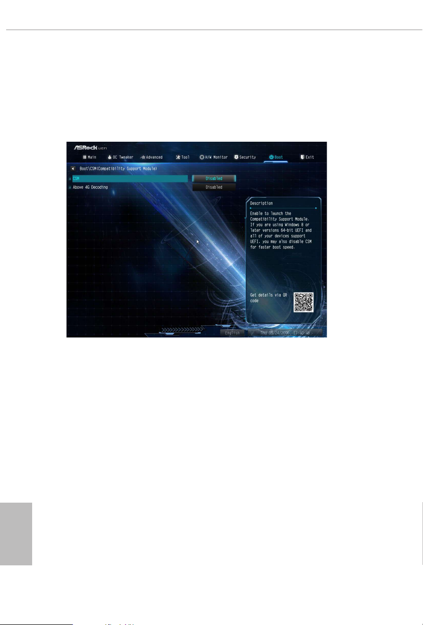
CSM (Compatibility Support Module)
CSM
Enable to launch the Compatibility Support Module. Please do not disable unless
you’re running a WHCK test.
English
86
Above 4G Decoding
Enable or disable 64bit capable Devices to be decoded in Above 4G Address Space
(only if the system supports 64 bit PCI decoding).
Launch PXE OpROM Policy
Select UEFI only to run those that support UEFI option ROM only. Select Legacy
only to run those that support legacy option ROM only. Select Do not launch to not
execute both legacy and UEFI option ROM.
Launch Storage OpROM Policy
Select UEFI only to run those that support UEFI option ROM only. Select Legacy
only to run those that support legacy option ROM only. Select Do not launch to not
execute both legacy and UEFI option ROM.
Page 93

X570 Extreme4
4.9 Exit Screen
Save Changes and Exit
When you select this option the following message, “Save conguration changes
and exit setup?” will pop out. Select [OK] to save changes and exit the UEFI SETUP
UTILITY.
Discard Changes and Exit
When you select this option the following message, “Discard changes and exit
setup?” will pop out. Select [OK] to exit the UEFI SETUP UTILITY without saving
any changes.
Discard Changes
When you select this option the following message, “Discard changes?” will pop
out. Select [OK] to discard all changes.
Load UEFI Defaults
Load UEFI default values for a ll options. e F9 key can be used for this operation.
Launch EFI Shell from lesystem device
Copy shellx64.e to the root directory to launch EFI Shell.
English
87
Page 94

Contact Information
If you need to contact ASRock or want to know more about ASRock, you’re welcome
to visit ASRock’s website at http://ww w.asrock.com; or you may contact your dealer
for further information. For technical questions, please submit a support request
form at https://event.asrock.com/tsd.asp
ASRock Incorporation
2F., No.37, Sec. 2, Jhongyang S. Rd., Beitou District,
Taipei City 112, Taiwan (R.O.C.)
ASRock EUROPE B.V.
Bijsterhuizen 11-11
6546 AR Nijmegen
e Netherlands
Phone: +31-24-345-44-33
Fax: +31-24-345-44-38
ASRock America, Inc.
13848 Magnolia Ave, Chino, CA91710
U.S.A.
Phone: +1-909-590-8308
Fax: +1-909-590-1026
Page 95

DECLARATION OF CONFORMITY
Per FCC Part 2 Section 2.1077(a)
Responsible Party Name: ASRock Incorporation
Address:
Phone/FaxNo:
hereby declares that the product
Product Name : Motherboard
13848 Magnolia Ave, Chino, CA91710
+1-909-590-8308/+1-909-590-1026
Model Number :
Conforms to the following specications:
FCC Part 15, Subpart B, Unintentional Radiators
Supplementary Information:
X570 Extreme4
is device complies with part 15 of the FCC Rules. Operation is subject to the
following two conditions: (1) is device may not cause harmful interference,
and (2) this device must accept any interference received, including interference
that may cause undesired operation.
James
Representative Person’s Name:
Signature :
Date :
May 12, 2017
Page 96

EU Declaration of Conformity
EMC —Directive 2014/30/EU (from April 20th, 2016)
☐
For the following equipment:
Motherboard
(Product Name)
X570 Extreme4 / ASRock
(Model Designation / Trade Name)
ASRock Incorporation
(Manufacturer Name)
2F., No.37, Sec. 2, Jhongyang S. Rd., Beitou District, Taipei City 112, Taiwan (R.O.C.)
(Manufacturer Address)
ڛ
☐ EN 55022:2010/AC:2011 Class B EN 55024:2010/A1:2015
ڛ EN 55032:2012+AC:2013 Class B ڛڛ EN 61000-3-3:2013
ڛ EN 61000-3-2:2014
☐
LVD —Directive 2014/35/EU (from April 20th, 2016)
EN 60950-1 : 2011+ A2: 2013 ☐
ڛ RoHS — Directive 2011/65/EU
ڛ CE marking
EN 60950-1 : 2006/A12: 2011
(EU conformity marking)
ASRock EUROPE B.V.
(Company Name)
Bijsterhuizen 1111 6546 AR Nijmegen e Netherlands
(Company Address)
Person responsible for making this declaration:
(Name, Surname)
A.V.P
(Position / Title)
July 5, 2019
(Date)
P/N: 15G062166000AK V1.0
 Loading...