

Page 1

Page 2

Version 1.0
Published November 2018
Copyright©2018 ASRock INC. All rights reserved.
Copyright Notice:
No part of this documentation may be reproduced, transcribed, transmitted, or
translated in any language, in any form or by any means, except duplication of
documentation by the purchaser for backup purpose, without written consent of
ASRock Inc.
Products and corporate names appearing in this documentation may or may not
be registered trademarks or copyrights of their respective companies, and are used
only for identication or explanation and to the owners’ benet, without intent to
infringe.
Disclaimer:
Specications and information contained in this documentation are furnished for
informational use only and subject to change without notice, and should not be
constructed as a commitment by ASRock. ASRock assumes no responsibility for
any errors or omissions that may appear in this documentation.
With respect to the contents of this documentation, ASRock does not provide
warranty of any kind, either expressed or implied, including but not limited to
the implied warranties or conditions of merchantability or tness for a particular
purpose.
In no event shall ASRock, its directors, ocers, employees, or agents be liable for
any indirect, special, incidental, or consequential damages (including damages for
loss of prots, loss of business, loss of data, interruption of business and the like),
even if ASRock has been advised of the possibility of such damages arising from any
defect or error in the documentation or product.
is device complies with Part 15 of the FCC Rules. Operation is subject to the following
two conditions:
(1) this device may not cause harmful interference, and
(2) this device must accept any interference received, including interference that
may cause undesired operation.
CALIFORNIA, USA ONLY
e Lithium battery adopted on this motherboard contains Perchlorate, a toxic substance
controlled in Perchlorate Best Management Practices (BMP) regulations passed by the
California Legislature. When you discard the Lithium battery in California, USA, please
follow the related regulations in advance.
“Perchlorate Material-special handling may apply, see ww w.dtsc.ca.gov/hazardouswaste/
perchlorate”
ASRock Website: http://www.asrock.com
Page 3

AUSTRALIA ONLY
Our goods come with guarantees that cannot be excluded under the Australian Consumer
Law. You are entitled to a replacement or refund for a major failure and compensation for
any other reasonably foreseeable loss or damage caused by our goods. You are also entitled
to have the goods repaired or replaced if the goods fail to be of acceptable quality and the
failure does not amount to a major failure. If you require assistance please call ASRock Tel
: +886-2-28965588 ext.123 (Standard International call charges apply)
Page 4

Contents
Chapter 1 Introduction 1
1.1 Package Contents 1
1.2 Specications 2
1.3 Motherboard Layout 7
1.4 I/O Panel 9
Chapter 2 Installation 11
2.1 Installing the CPU 12
2.2 Installing the CPU Liquid Cooler 16
2.3 Installing the CPU Cooler 18
2.4 Installation of Memory Modules (DIMM) 21
2.5 Expansion Slots (PCI Express Slots) 23
2.6 Onboard Headers and Connectors 24
2.7 Smart Switches 29
2.8 SLITM , 3-Way SLI
TM
and Quad SLITM Operation Guide 30
2.8.1 Installing Two SLITM-Ready Graphics Cards 30
2.8.2 Installing Three SLITM-Ready Graphics Cards 32
2.8.3 Driver Installation and Setup 34
2.9 CrossFireXTM, 3-Way CrossFireX
TM
and Quad CrossFireXTM
Operation Guide 35
2.9.1 Installing Two CrossFireXTM-Ready Graphics Cards 35
2.9.2 Installing Three CrossFireXTM-Ready Graphics Cards 36
2.9.3 Driver Installation and Setup 37
Page 5

2.10 M.2 WiFi/BT Module Installation Guide 38
2.11 M.2_SSD (NGFF) Module Installation Guide (M2_1) 40
2.12 M.2_SSD (NGFF) Module Installation Guide (M2_2) 43
2.13 M.2_SSD (NGFF) Module Installation Guide (M2_3) 47
Chapter 3 Software and Utilities Operation 51
3.1 Installing Drivers 51
3.2 Phantom Gaming Tuning 52
3.2.1 Installing Phantom Gaming Tuning 52
3.2.2 Using Phantom Gaming Tuning 52
3.3 ASRock Live Update & APP Shop 55
3.3.1 UI Overview 55
3.3.2 Apps 56
3.3.3 BIOS & Drivers 59
3.3.4 Setting 60
3.4 Creative SoundBlaster Cinema5 61
3.5 ASRock Polychrome RGB 62
Chapter 4 UEFI SETUP UTILITY 65
4.1 Introduction 65
4.1.1 UEFI Menu Bar 65
4.1.2 Navigation Keys 66
4.2 Main Screen 67
4.3 OC Tweaker Screen 68
4.4 Advanced Screen 71
4.4.1 CPU Conguration 72
Page 6

4.4.2 North Bridge Conguration 73
4.4.3 South Bridge Conguration 74
4.4.4 Storage Conguration 75
4.4.5 Super IO Conguration 76
4.4.6 ACPI Conguration 77
4.4.7 Trusted Computing 78
4.4.8 AMD CBS 79
4.4.9 AMD PBS 89
4.5 Tools 90
4.6 Hardware Health Event Monitoring Screen 91
4.7 Security Screen 94
4.8 Boot Screen 95
4.9 Exit Screen 97
Page 7

X399 Phantom Gaming 6
Chapter 1 Introduction
ank you for purchasing ASRock X399 Phantom Gaming 6 motherboard, a
reliable motherboard produced under ASRock’s consistently stringent quality
control. It delivers excellent performance with robust design conforming to
ASRock’s commitment to quality and endurance.
In this documentation, Chapter 1 and 2 contains the introduction of the
motherboard and step-by-step installation guides. Chapter 3 contains the operation
guide of the soware and utilities. Chapter 4 contains the conguration guide of
the BIOS setup.
Becau se the motherboard specications and the BIOS soware might be updated, the
content of this documentation will be subject to change without notice. In case any modications of this documentation occur, the updated version will be available on ASRock’s
website w ithout further notice. If you require technical support related to this motherboard, please visit our website for specic information about the model you are using. You
may nd the l atest VGA cards and CPU suppor t list on ASRock’s website a s well. ASRock
website http://www.asrock.com.
1.1 Package Contents
ASRock X399 Phantom Gaming 6 Motherboard (ATX Form Factor)
•
ASRock X399 Phantom Gaming 6 Quick Installation Guide
•
ASRock X399 Phantom Gaming 6 Support CD
•
1 x I/O Panel Shield
•
4 x Serial ATA (SATA) Data Cables (Optional)
•
1 x ASRock SLI_HB_Bridge_2S Card (Optional)
•
4 x Screws for M.2 Sockets (Option al)
•
1 x WiFi Bracket (Optional)
•
English
1
Page 8

1.2 Specications
Platform
CPU
Chipset
Memory
Expansion
Slot
•
•
•
•
•
•
•
•
•
•
* Please refer to Memory Support List on ASRock’s website for
more information. (http://www.asrock.com/)
•
•
•
* Supports NVMe SSD as boot disks
•
•
•
•
ATX Form Factor
8 Layer PCB
Supports AMD TR4 Socket Ryzen readripper Series CPUs
Supports CPU up to 180W
Digi Power design
8 Power Phase design
AMD X399
Quad Channel DDR4 Memory Technology
8 x DDR4 DIMM Slots
Supports DDR4 3400+(OC)/3200(OC)/2933(OC)/
2667/2400/2133 ECC & non-ECC, un-buered memory*
Max. capacity of system memory: 128GB
15μ Gold Contact in DIMM Slots
3 x PCI Express 3.0 x16 Slots (PCIE1/PCIE2/PCIE3: single at
x16 (PCIE1); dual at x16 (PCIE1) / x16 (PCIE2); triple at x16
(PCIE1) / x16 (PCIE2) / x16 (PCIE3))*
Supports AMD Quad CrossFireXTM, 3-Way CrossFireXTM
and CrossFireXTM
Supports NVIDIA® Quad SLITM, 3-Way SLITM and SLI
1 x M.2 Socket (Key E), supports ty pe 2230 WiFi/BT module
15μ Gold Contact in VGA PCIe Slot (PCIE1, PCIE2 and
PCIE 3)
TM
English
2
Audio
7.1 CH HD Audio with Content Protection (Realtek
•
ALC1220 Audio Codec)
Premium Blu-ray Audio support
•
Supports Surge Protection
•
Nichicon Fine Gold Series Audio Caps
•
120dB SNR DAC with Dierential Amplier
•
Page 9

X399 Phantom Gaming 6
NE5532 Premium Headset Amplier for Front Panel Audio
•
Connector (Supports up to 600 Ohm headsets)
Pure Power-In
•
Direct Drive Technology
•
PCB Isolate Shielding
•
Impedance Sensing on Rear Out port
•
Individual PCB Layers for R/L Audio Channel
•
Gold Audio Jacks
•
15μ Gold Audio Connector
•
Supports Creative SoundBlaster Cinema5
•
LAN
Rear Panel
I/O
1 x 2.5 Gigabit LAN 10/100/1000/2500 Mb/s (Dragon
RTL8125AG)
Supports Phantom Gaming LAN Soware
•
- Smart Auto Adjust Bandwidth Control
- Visual User Friendly UI
- Visual Network Usage Statistics
- Optimized Default Setting for Game, Browser, and
Streaming Modes
- User Customized Priority Control
Supports Wake-On-LAN
•
Supports Lightning/ESD Protection
•
Supports Energy Ecient Ethernet 802.3az
•
Supports PXE
•
1 x Gigabit LAN 10/100/1000 Mb/s (Intel® I211AT)
Supports Wake-On-LAN
•
Supports Lightning/ESD Protection
•
Supports Energy Ecient Ethernet 802.3az
•
Supports PXE
•
1 x PS/2 Mouse/Keyboard Port
•
1 x Optical SPDIF Out Port
•
1 x USB 3.1 Gen2 Type-A Port (10 Gb/s) (Supports ESD
•
Protection)
1 x USB 3.1 Gen2 Type-C Port (10 Gb/s) (Supports ESD
•
Protection)
8 x USB 3.1 Gen1 Ports (Supports ESD Protection)
•
2 x RJ-45 LAN Ports with LED (ACT/LINK LED and SPEED
•
LED)
HD Audio Jacks: Rear Speaker / Centra l / Bass / Line in /
•
Front Speaker / Microphone (Gold Audio Jacks)
English
3
Page 10

English
Storage
Connector
8 x SATA3 6.0 Gb/s Connectors, support RAID (RAID 0,
•
RAID 1 and RAID 10), NCQ, AHCI and Hot Plug
1 x Ultra M.2 Socket (M2_1), supports M Key type
•
2230/2242/2260/2280/22110 M.2 PCI Express module up to
Gen3 x4 (32 Gb/s)**
1 x Ultra M.2 Socket (M2_2), supports M Key ty pe
•
2242/2260/2280 M.2 PCI Express module up to Gen3 x4 (32
Gb/s)*
1 x Ultra M.2 Socket (M2_3), supports M Key ty pe
•
2230/2242/2260/2280 M.2 SATA3 6.0 Gb/s module and M.2
PCI Express module up to Gen3 x4 (32 Gb/s)**
* Supports NVMe SSD as boot disks
* Supports ASRock U.2 Kit
1 x TPM Header
•
1 x Power LED and Speaker Header
•
2 x RGB LED Headers
•
* Support in total up to 12V/3A, 36W LED Strip
1 x Addressable LED Header
•
* Supports in total up to 5V/3A, 15W LED Strip
1 x CPU Fan Connector (4-pin)
•
* e CPU Fan Connector supports the CPU fan of ma ximum
1A (12W) fan power.
1 x CPU/Water Pump Fan Connector (4-pin) (Smart Fan
•
Speed Control)
* e CPU/Water Pump Fan supports the water cooler fan of
maximum 2A (24W) fan power.
3 x Chassis/Water Pump Fan Connectors (4-pin) (Smart Fan
•
Speed Control)
* e Chassis/Water Pump Fan supports the water cooler fan of
maximum 2A (24W) fan power.
* CPU_FAN2/WP, CHA_FAN1/WP, CHA_FAN2/WP and
CHA_FAN3/WP can auto detect if 3-pin or 4-pin fan is in use.
1 x 24 pin ATX Power Connector
•
2 x 8 pin 12V Power Connectors
•
1 x Front Panel Audio Connector (15μ Gold Audio
•
Connector)*
1 x Right Angle Front Panel Audio Connector*
•
* Connect the audio device to either one of the audio connec-
tors.
4
Page 11

BIOS
Feature
Hardware
Monitor
X399 Phantom Gaming 6
1 x AMD LED Fan USB Header
•
2 x USB 2.0 Headers (Support 4 USB 2.0 ports) (Supports
•
ESD Protection)
2 x USB 3.1 Gen1 Headers (Support 4 USB 3.1 Gen1 ports)
•
(Supports ESD Protection)
1 x Clear CMOS Button
•
1 x Power Button with LED
•
1 x Reset Button with LED
•
AMI UEFI Legal BIOS with GUI support
•
Supports “Plug and Play”
•
ACPI 5.1 compliance wake up events
•
Supports jumperfree
•
SMBIOS 2.3 support
•
VCORE, VCORE_NB, DRAM, VPPM, PCH 1.05V, +1.8V,
•
+1.8VSB, VDDCR_SOC_S5, PROM 2.5V, Voltage Multi-
adjustment
Temperature Sensing: CPU, CPU/Water Pump, Chassis/Wa-
•
ter Pump Fans
Fan Tachometer: CPU, CPU/Water Pump, Chassis/Water
•
Pump Fans
Quiet Fan (Auto adjust chassis fan speed by CPU tempera-
•
ture): CPU, CPU/Water Pump, Chassis/Water Pump Fans
Fan Multi-Speed Control: CPU, CPU/Water Pump, Chassis/
•
Water Pump Fans
Voltage monitoring: +12V, +5V, +3.3V, CPU Vcore, VCORE_
•
NB, DRAM, PCH 1.05V, +1.8V, VDDCR_ SOC
Microso® Windows® 10 64-bit
OS
Certications
* For detailed product information, please visit our website: http://www.asrock .com
•
FCC, CE
•
ErP/EuP ready (ErP/EuP ready power supply is required)
•
English
5
Page 12

Please realiz e that the re is a certain r isk involved with o verclocking, including adjusting
the setting in the BIOS, applying Untied Overclocking Technolog y, or using third-party
overclocking to ols. O verclocking may aect your system’s stability, or even c ause damage to
the components and devices of your system. It should be don e at your ow n risk and expense.
We are not responsibl e for possible damage caused by overclo cking.
English
6
Page 13
ATXP WR 1
AMD
X399
LAN
PCIE1
Top:
Central/Bass
Center :
REAR SPK
Top:
LINE IN
Center :
FRONT
Bottom :
Optica l
SPDIF
Bottom :
MIC IN
PCIE2
HDLED RESET
PLED PWRBTN
PANEL1
1
USB_3_4
1
1
USB_1_2
1
HD_AUDIO1
1
HD_AUDIO_RA1
SATA3_3_4
SATA3_5_6
CPU_FAN1
RoH S
10
13
14
15
SATA3_7_8
16
24
2531 2930
SATA3_1_2
1
5
DDR 4_D1 (6 4 bit, 28 8-pin m odule )
DDR 4_D2 (6 4 bit, 28 8-pin m odule )
DDR 4_C1 (6 4 bit, 28 8-pin m odule )
DDR 4_C2 (6 4 bit, 28 8-pin m odule )
32
27 19
20
CHA_FAN1
/WP
32
DDR 4_A2 (6 4 bit, 28 8-pin m odule )
DDR 4_A1 (6 4 bit, 28 8-pin m odule )
DDR 4_B2 (6 4 bit, 28 8-pin m odule )
DDR 4_B1 (6 4 bit, 28 8-pin m odule )
8
6
TR4 Socket
(4094 pins)
USB3_11 _12
1
SPK_PLED1
AUDIO
CODEC
11
1
1
USB3_9_10
18
28
Top:
RJ-45
Top:
RJ-45
USB 3.1 Gen1
T: USB3
B: USB4
USB 3.1 Gen1
T: USB5
B: USB6
USB 3.1 G en1
T: USB1
B: USB2
PS2
Keyb oard
/Mous e
BIOS
ROM
ATX12V2
PCIE3
RGB_LED1
1
M2_2
M2_3
ATX12V1
4
CPU_FAN2/WP
RGB_LED2
1
2122
23
26
CHA_FAN2
/WP
CHA_FAN3
/WP
1
TPMS1
ADDR_LED1
1
X399 Phantom Gaming 6
CMOS
Battery
M2_1
CT2CT3CT4CT5 CT1
USB 3.1 Gen2
T: USB31_TA_1
B: USB31_TC_1
USB 3.1 Gen1
T: USB7
B: USB8
7
9
RSTBTN1
CLRCBTN1
PWRBTN1
17
1
USB_5
12
M2_4
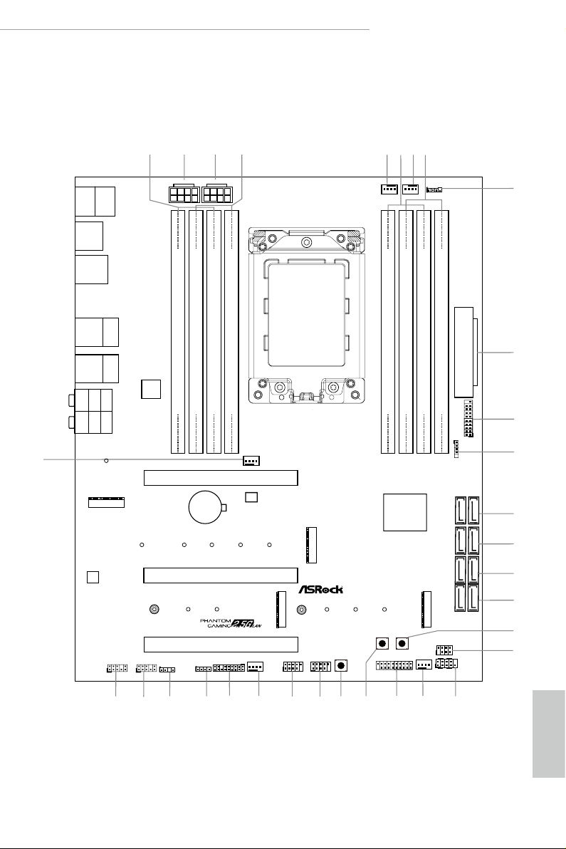
1.3 Motherboard Layout
X399 Phantom Gaming 6
English
7
Page 14

English
No. Description
1 2 x 288-pin DDR4 DIMM Slots (DDR4_D2, DDR4_C2)
2 ATX 12V Power Connector (ATX12V2)
3 ATX 12V Power Connector (ATX12V1)
4 2 x 288-pin DDR4 DIMM Slots (DDR4_D1, DDR4_C1)
5 CPU Fan Connector (CPU_FAN1)
6 2 x 288-pin DDR4 DIMM Slots (DDR4_A1, DDR4_B1)
7 CPU/Water Pump Fan Connector (CPU_FAN2/WP)
8 2 x 288-pin DDR4 DIMM Slots (DDR4_A2, DDR4_B2)
9 RGB LED Header (RGB_LED2)
10 ATX Power Connector (ATXPWR1)
11 USB 3.1 Gen1 Header (USB3_11_12)
12 AMD LED Fan USB Header (USB_5)
13 SATA3 Connectors (SATA3_1_2)
14 SATA3 Conne ctors (SATA3_3_4)
15 SATA3 Connectors (SATA3_5_6)
16 SATA3 Connectors (SATA3_7_8)
17 Power Button (PWRBTN1)
18 Power LED and Speaker Header (SPK_PLED1)
19 System Panel Header (PANEL1)
20 Chassis/Water Pump Fan Connector (CHA_FAN1/WP)
21 USB 3.1 Gen1 Header (USB3_9_10)
22 Reset Button (RSTBTN1)
23 Clear CMOS Button (CLRCBTN1)
24 USB 2.0 Header (USB_1_2)
25 USB 2.0 Header (USB_3_4)
26 Chassis/Water Pump Fan Connector (CHA_FAN2/WP)
27 TPM Header (TPMS1)
28 RGB LED Header (RGB_LED1)
29 Addressable LED Header (ADDR_LED1)
30 Right Angle Front Panel Audio Header (HD_AUDIO_RA1)
31 Front Panel Audio Header (HD_AUDIO1)
32 Chassis/Water Pump Fan Connector (CHA_FAN3/WP)
8
Page 15
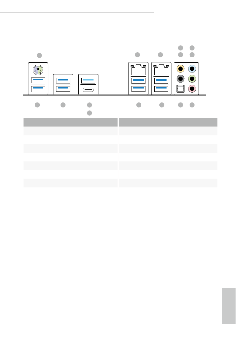
1.4 I/O Panel
1
X399 Phantom Gaming 6
6
2
3
547
15 14 89
No. Description No. Description
1 PS/2 Mouse/Keyboard Port 9 Optical SPDIF Out Port
2 LAN RJ-45 Port (I211AT)* 10 USB 3.1 Gen1 Ports (USB3_7_8)
3 LAN RJ-45 Port (Dragon RTL8125AG)** 11 USB 3.1 Gen1 Ports (USB3_5_6)
4 Central / Bass (Orange) 12 USB 3.1 Gen2 Type-A Port (USB31_TA_1)
5 Rear Speaker (Black) 13 USB 3.1 Gen2 Type-C Port (USB31_TC_1)
6 Line In (Light Blue) 14 USB 3.1 Gen1 Ports (USB3_3_4)
7 Front Speaker (Lime)*** 15 USB 3.1 Gen1 Ports (USB3_1_2)
8 Microphone (Pink)
12
13
11
10
English
9
Page 16
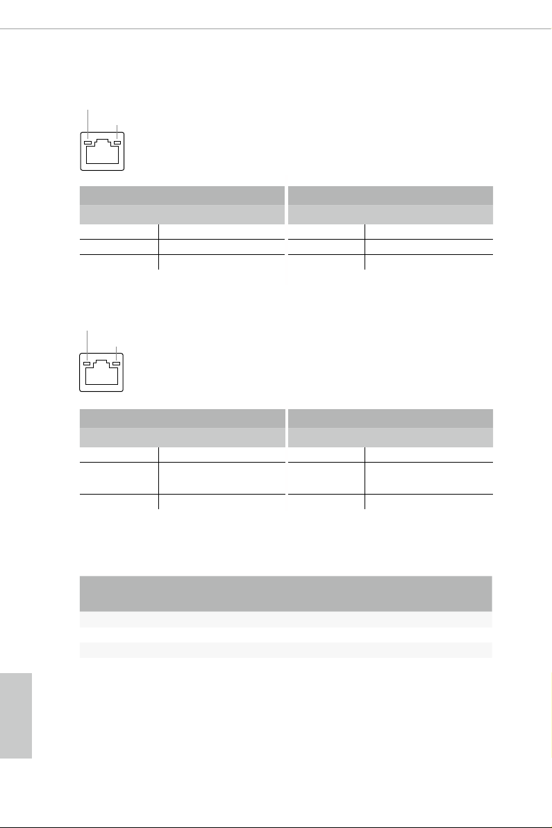
* ere are two LEDs on each LAN port. Please refer to the table below for the LAN port LED indications.
ACT/LINK LED
SPEED LED
LAN Por t
Activity / Link LED Speed LED
Status Description Status Description
O No Link O 10Mbps connection
Blinking Data Activity Orange 100Mbps connection
On Link Green 1Gbps connection
* ere are two LEDs on each LAN port. Please refer to the table below for the LAN port LED indications.
ACT/LINK LED
SPEED LED
LAN Por t
Activity / Link LED Speed LED
Status Description Status Description
O No Link O 10Mbps connection
Blinking Data Activity Orange
100Mbps/1Gbps
connection
On Link Green 2.5Gbps connection
English
10
*** If you use a 2-channe l speak er, please connect the spe aker’s plug into “Front Speaker Jack”. See the table below
for connection d etails in accordance w ith the type of speaker you use.
Audio Output
Channels
Front Speaker
(No. 7)
Rear Speaker
(No. 5)
Central / Bass
(No. 4)
Line In
(No. 6)
2 V -- -- --
4 V V -- --
6 V V V --
8 V V V V
Page 17

X399 Phantom Gaming 6
Chapter 2 Installation
is is an ATX form factor motherboard. Before you install the motherboard, study
the conguration of your chassis to ensure that the motherboard ts into it.
Pre-installation Precautions
Take note of the following precautions before you install motherboard components
or change any motherboard settings.
Make sure to unplug the power cord before installing or removing the motherboard
•
components. Failure to do so may cause physical injuries and damages to motherboard
components.
In order to avoid damage from static electricity to the motherboard’s components,
•
NEVER place your motherboard directly on a carpet. Also remember to use a grounded
wrist strap or touch a safety grounded object before you handle the components.
Hold components by the edges and do not touch the ICs.
•
Whenever you uninstall any components, place them on a grounded anti-static pad or
•
in the bag that comes with the components.
When placing screws to secure the motherboard to the chassis, please do not over-
•
tighten the screws! Doing so may damage the motherboard.
11
English
Page 18
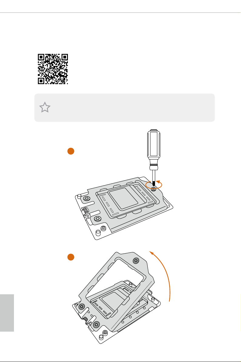
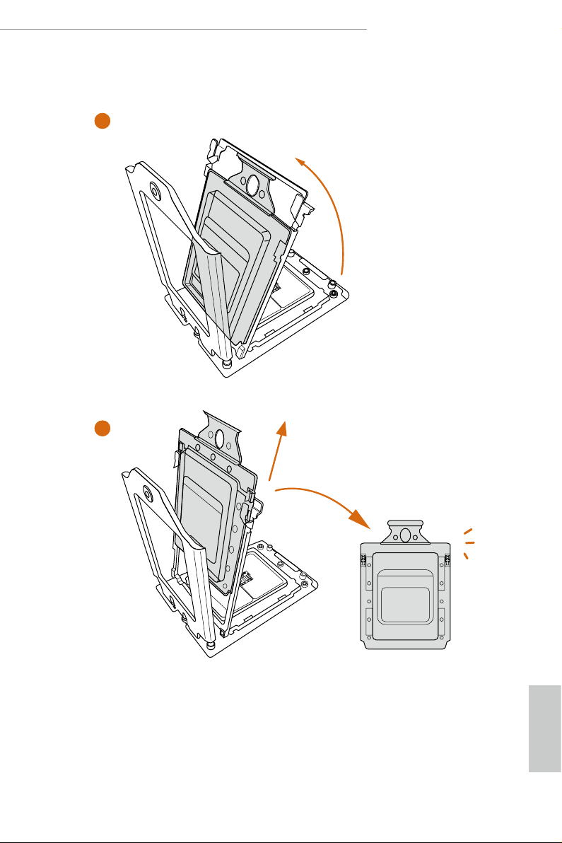
2.1 Installing the CPU
Tutorial Video
Unplug all power cables be fore installing the CPU.
1
English
12
2
Page 19
X399 Phantom Gaming 6
3
4
13
English
Page 20
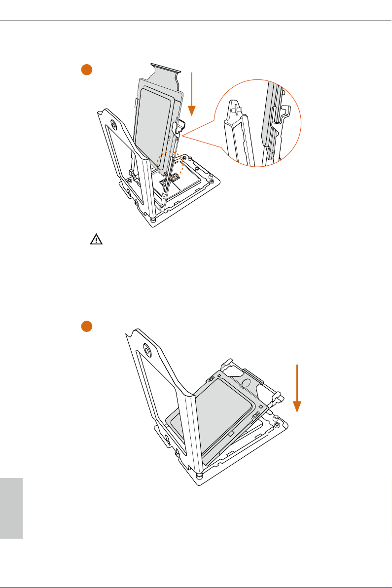
5
Carrier Fram e with CPU
Rail Frame
Please make sure that the carrier
frame with CPU is closely attached to
the rail frame while inserting it.
English
Install the orange carrier frame with CPU. Don’t separate them.
6
14
Page 21
X399 Phantom Gaming 6
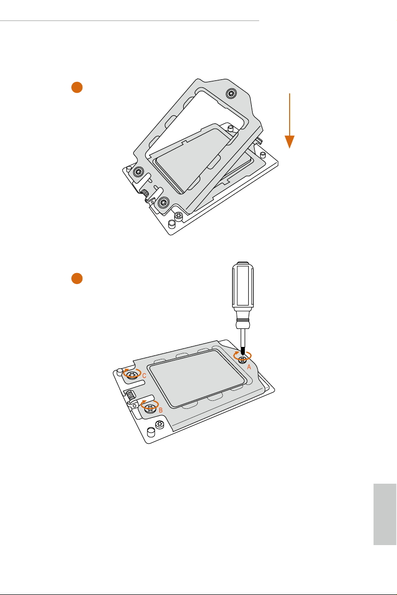
7
8
15
English
Page 22
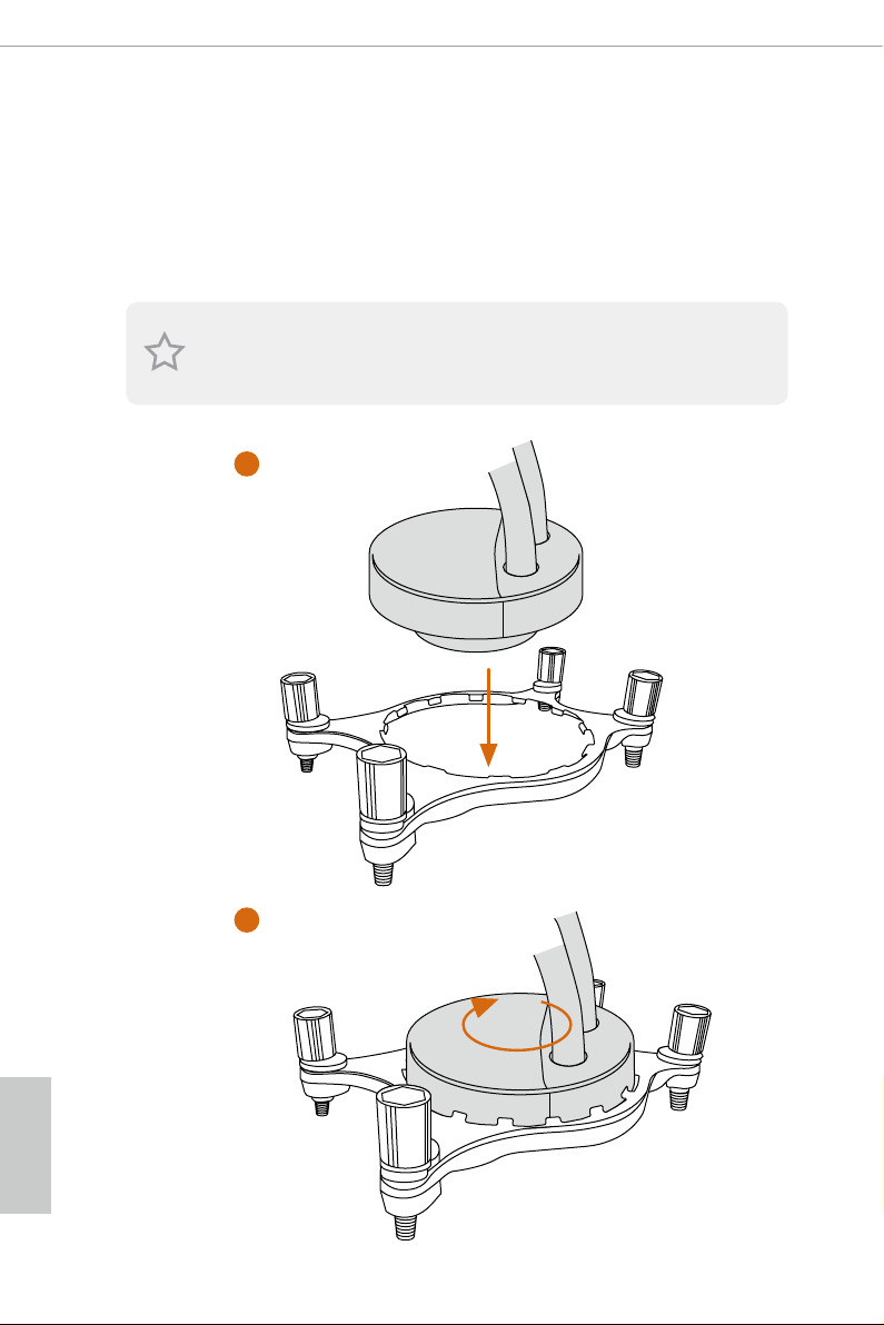
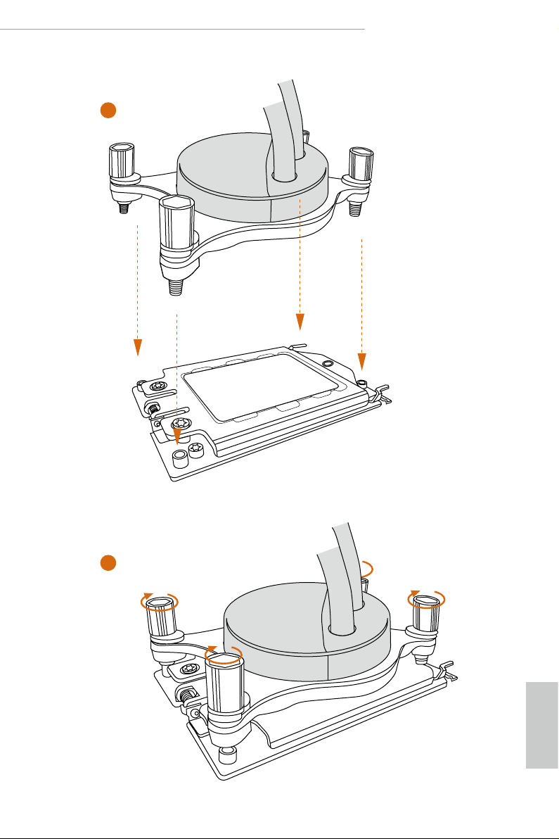
2.2 Installing the CPU Liquid Cooler
Aer you install the CPU into this motherboard, it is necessary to install a larger
heatsink and cooling fan to dissipate heat. You also need to spray thermal grease
between the CPU and the heatsink to improve heat dissipation. Ma ke sure that the
CPU and the heatsink are securely fastened and in good contact with each other.
Please turn o the power or remove th e power cord before changing a CPU or heatsink.
1
English
16
2
Page 23
X399 Phantom Gaming 6
3
4
English
17
Page 24
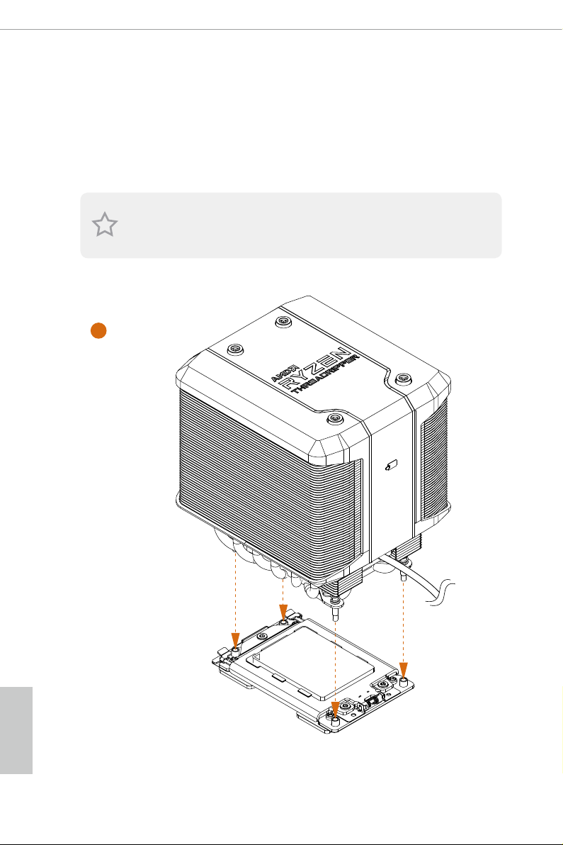
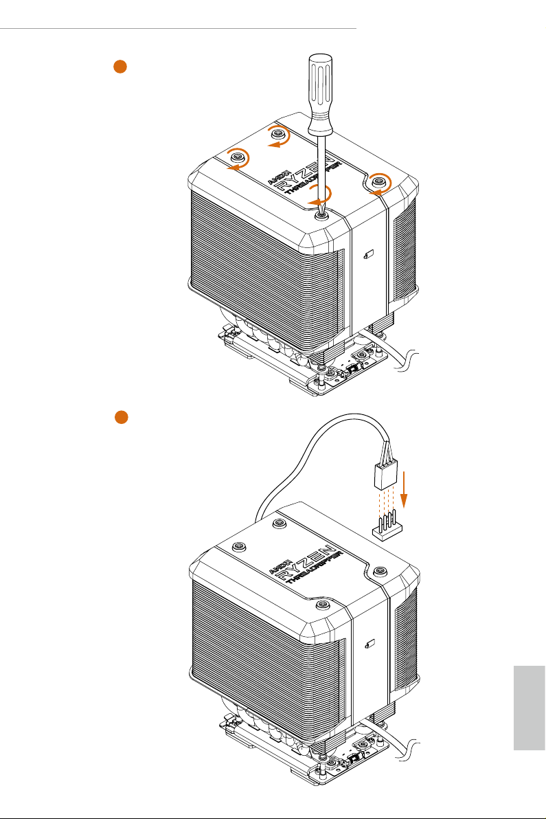
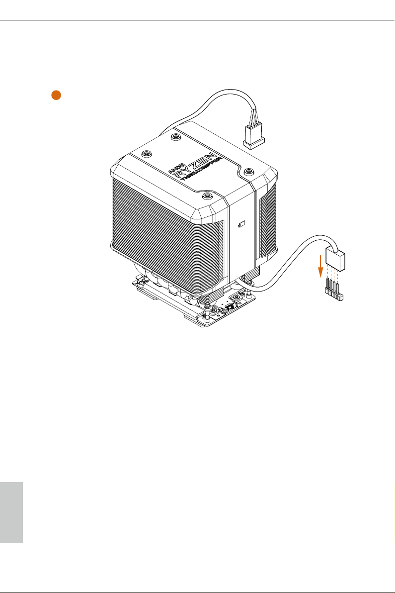
2.3 Installing the CPU Cooler
Aer you install the CPU into this motherboard, it is necessary to install a larger
heatsink and cooling fan to dissipate heat. You also need to spray thermal grease
between the CPU and the heatsink to improve heat dissipation. Ma ke sure that the
CPU and the heatsink are securely fastened and in good contact with each other.
Please turn o the power or remove th e power cord before changing a CPU or heatsink.
1
English
18
Page 25
X399 Phantom Gaming 6
2
B
C
D
A
3
1
N
FA
_
U
P
C
English
19
Page 26
4
1
N
FA
_
U
P
C
U
S
B
_
5
English
20
Page 27
X399 Phantom Gaming 6
D2
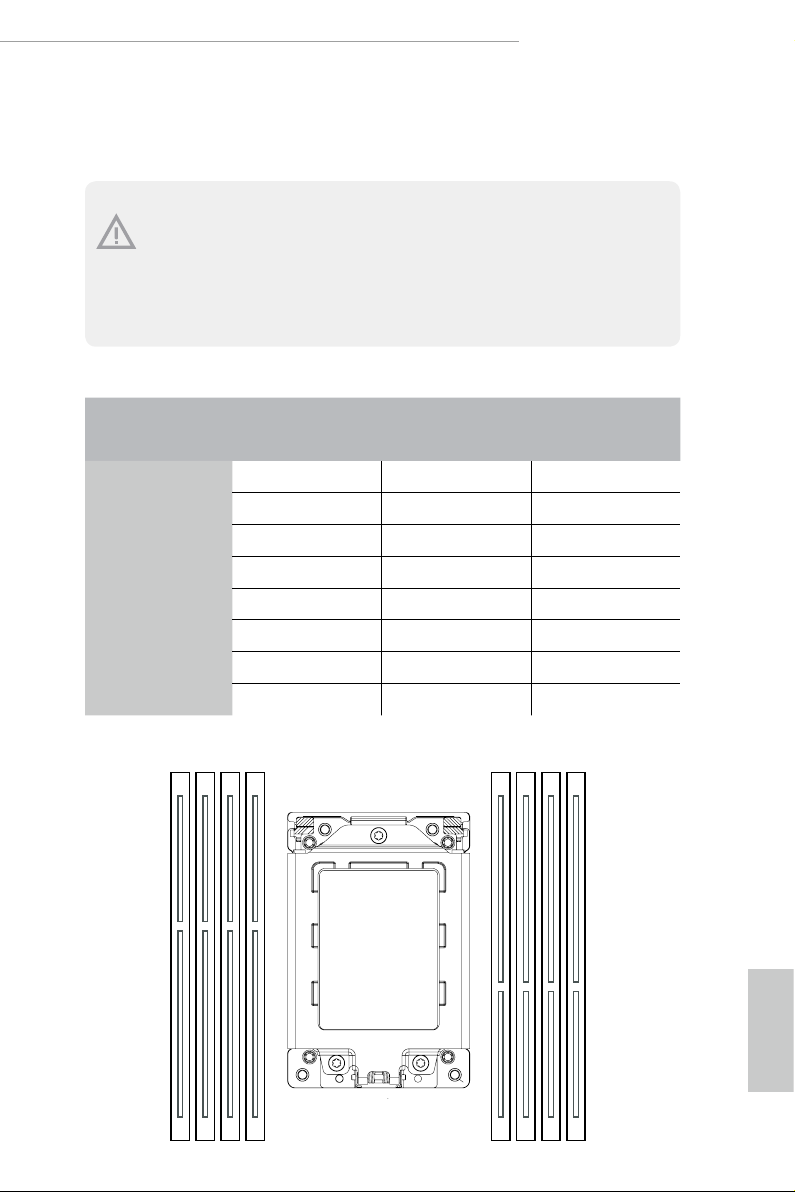
2.4 Installation of Memory Modules (DIMM)
is motherboard provides eight 288-pin DDR4 (Double Data Rate 4) DIMM slots, and
supports Quad Channel Memory Technology.
1. For quad chann el cong uration, you always need to install identical (the same brand,
speed , size and chip-type) DDR4 DIMM pairs.
2. It is not allowed to install a DDR, DDR2 or DDR3 memory module into a DDR4 sl ot;
otherwise , this motherboard and DIM M may be damaged.
3. e DIMM only ts in one correct orientation. It will cause permanent damage to the
motherboard and the DIMM if you force the DIMM into the slot at incorrect orientation.
Memory Conguration
2 - DIMM 4 - DIMM 8 - DIMM
Priority 1 2 3
DDR4_D2
DDR4_D1
DDR4_C2
DDR4_C1
DDR4_A1
DDR4_A2
DDR4_B1
DDR4_B2
Populated Populated Populated
Populated Populated Populated
Populated Populated
Populated
Populated Populated
Populated
Populated
Populated
D1 C2 C1 A1 A2 B1 B2
English
21
Page 28
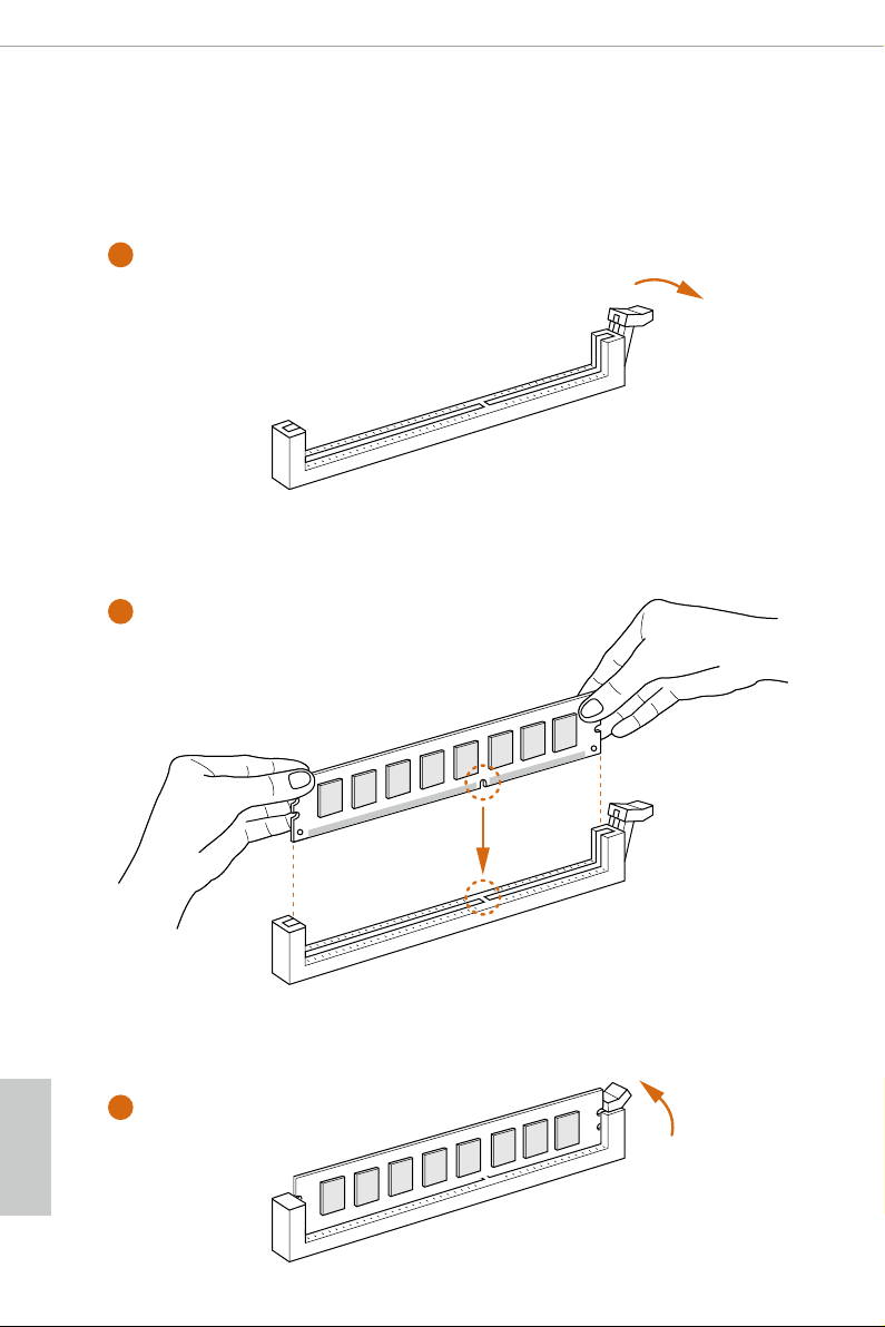
If only two memory modules are installed in the DDR4 DIMM slots, then Dual Channel
•
Memory Technology is activated. If three memory modules are insta lled, then Triple
Channel Memory Technology is activated. If more than four memory modules are installed
in the DDR4 DIMM slots, then Quad Channel Memory Technology is activated.
1
2
English
22
3
Page 29

X399 Phantom Gaming 6
2.5 Expansion Slots (PCI Express Slots)
ere are 3 PCI Express slots on the motherboard.
Before installing an ex pansion card, please make sure that the power supply is switched o
or the power cord is unplug ged. Pl ease re ad the documentation of the expansion card and
make necessary hardware settings for the card before you start the installation.
PCIe slots:
PCIE1 (PCIe 3.0 x16 slot) is used for PCI Express x16 lane width graphics cards.
PCIE2 (PCIe 3.0 x16 slot) is used for PCI Express x16 lane width graphics cards.
PCIE3 (PCIe 3.0 x16 slot) is used for PCI Express x16 lane width graphics cards.
PCIe Slot Congurations
PCIE1 PCIE2 PCIE3
Single Graphics Card x16 N/A N/A
Two Graphics Cards in
CrossFireXTM or SLITM
Mode
ree Graphics Cards in
3-Way CrossFireXTM Mode
or 3-Way SLITM Mode
For a better ther mal environme nt, ple ase connect a ch assis fan to the motherboard’s
chassis fan connector (CHA_ FAN1/WP, CHA_ FAN2/WP or CHA_ FAN3/WP) when u sing
multiple graphics cards.
x16 x16 N/A
x16 x16 x16
English
23
Page 30
2.6 Onboard Headers and Connectors
1
1
+5V
DUMMY
PLED+
PLED+
PLED-
DUMMY
SPEAKER
Onboard headers and connectors are NOT jump ers. Do NOT place jumper caps over
these headers and connectors. Placing jumper caps over the headers and connectors
will cause permanent damage to the motherboard.
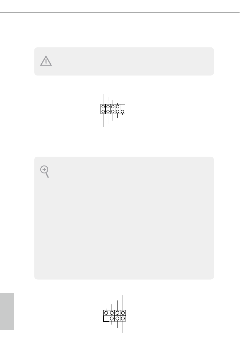
System Panel Header
(9-pi n PANEL1)
(see p.7, No. 19)
PWRBTN (Power Button):
Connec t to the power button on the ch assi s front panel. You may congure the way to tur n
o your system using the power button.
RESET (Reset B utton):
Connec t to the reset button on the ch assi s front panel. P ress the reset button to re start the
computer if the computer f reezes and fails to per form a normal restar t.
PLED (Syste m Power LED):
Connec t to the power status indicator on the chas sis front panel. e LED i s on when the
system is operating. e LED keeps blinking when the system is in S1/S3 sleep state. e
LED is o when the system is in S4 slee p state or powered o (S5).
HDLED (Ha rd Drive Activity LED):
Connec t to the hard drive ac tivity LED on the chassis front panel. e LED is on when the
hard drive is reading or wr iting data.
e front panel de sign may dier by chassis. A front panel module mainly consists of powe r
button, reset button , power LED, hard dr ive activity LED, speaker and etc. When connecting your ch assi s front panel module to thi s header, make sure the wire a ssignments and the
pin assignments are matched correctly.
PLED+
PLED-
HDLED-
HDLED+
PWRBTN#
GND
GND
RESET#
GND
Connect the power
button, reset button and
system status indicator on
the chassis to this header
according to the pin
assignments below. Note
the positive and negative
pins before connecting
the cables.
English
24
Power LED and Speaker
Header
(7-pin SPK_PLED1)
(see p.7, No. 18)
Please connect the
chassis power LED and
the chassis speaker to this
header.
Page 31

X399 Phantom Gaming 6
DUMMY
GND
GND
P+
P-
USB_PWR
P+
P-
USB_PWR
1
1
ID
I
1
Serial ATA3 Connectors
(SATA3_1_2:
see p.7, No. 13)
(SATA3_3_4:
see p.7, No. 14)
(SATA3_ 5_6:
see p.7, No. 15)
(SATA3_ 7_ 8:
see p.7, No. 16)
AMD LED Fan USB
Header
(4-pin USB_5)
(see p.7, No. 12)
USB 2.0 Headers
(9-pin USB_1_2)
(see p.7, No. 24)
(9-pin USB_3_4)
(see p.7, No. 25)
SATA3_1
SATA3_3
SATA3_5SATA3_7
USB_PWR
GND
ese eight SATA3
connectors support SATA
SATA3_2
data cables for internal
storage devices with up to
6.0 Gb/s data transfer rate.
SATA3_4
SATA3_6SATA3_8
is header is used for
P-
P+
connecting the USB
connector on the AMD
Heatsink.
ere are two headers
on this motherboard.
Each USB 2.0 header can
support two ports.
USB 3.1 Gen1 Headers
(19-pin USB3_9_10)
(see p.7, No. 21)
(19-pin USB3_11_12)
(see p.7, No. 11)
IntA_P_SSRX +
ntA_P_SSRX -
Vbu s
Vbu s
IntA_P_SSRX -
IntA_P_SSRX +
IntA_PA_SSRX-
IntA_PA_SSRX+
IntA_PA_SSTX-
IntA_PA_SSTX+
IntA_PA_D-
IntA_PA_D+
IntA_P_SSTX-
IntA_P_SSTX+
GN D
GN D
IntA_P_SSTX-
IntA_P_SSTX+
Vbus
GND
GND
IntA_P_D +
IntA_P_D -
GN D
IntA_P_D -
VbusVbus
IntA_PB_SSRX-
IntA_PB_SSRX+
GND
IntA_PB_SSTX-
IntA_PB_SSTX+
GND
IntA_PB_D-
IntA_PB_D+
Dummy
1
GN D
IntA_P_D +
ere are two headers on
this motherboard. Each
USB 3.1 Gen1 header can
support two ports.
English
25
Page 32

Front Panel Audio
J_SENSE
OUT2_L
1
MIC_RET
PRESENCE#
GND
OUT2_R
MIC2_R
MIC2_L
OUT_RET
4 3 2 1
GND
1 2 3 4
Headers
(9-pin HD_ AUDIO1)
(see p.7, No. 31)
(9-pin HD_AUDIO_RA1)
(see p.7, No. 30)
1. High Denition Audio support s Jack Sensing, but the panel wire on the cha ssis
must support HDA to function cor rectly. Please follow the instr uctions in our
manual and chassis manual to in stall your system.
2. If you use an AC’97 audio panel , please install it to th e front panel audio header by
the steps below:
A. Connect Mic_IN (MIC) to MIC2_ L.
B. Conne ct Audio_R (RIN) to OUT2_R and Audio_ L (LIN) to OUT2_ L.
C. Connect Ground (GND) to Ground (GND).
D. MIC_ RET and OUT_RET are for the HD audio panel only. You don’t ne ed to
connec t them for the AC’97 audio panel.
E. To activate the front mic, go to the “FrontMic” Tab in the Realtek Control panel
and adjust “Recording Volume”.
ese two headers are for
connecting audio devices
to the front audio panel.
* Connect the audio
device to either one of the
audio connectors.
English
26
Chassis/Water Pump Fan
Connectors
(4-pin CHA_FAN1/WP)
(see p.7, No. 20)
(4-pin CHA_FAN2/WP)
(see p.7, No. 26)
(4-pin CHA_FAN3/WP)
(see p.7, No. 32)
CPU Fan Connector
(4-pin CPU_FAN1)
(see p.7, No. 5)
FAN_VOLTAGE
FAN_SPEED
FAN_SPEED_CONTROL
GND
FAN_VOLTAGE
CPU_F
AN_SPEED
FAN_SPEED_CONTROL
is motherboard
provides three 4-Pin water
cooling
chassis
fan
connectors. If you plan to
connect a 3-Pin
chassis
water cooler fan, please
connect it to Pin 1-3.
is motherboard
provides a 4-Pin CPU fan
(Quiet Fan) connector.
If you plan to connect a
3-Pin CPU fan, please
connect it to Pin 1-3.
Page 33

X399 Phantom Gaming 6
FAN_SPEED_CONTROL
4 3 2 1
4
8
SMB _DA TA_ MAI N
#
CPU/Water Pump Fan
Connector
(4-pin CPU_FAN2/WP)
(see p.7, No. 7)
ATX Power Connector
(24-p i n ATX PWR1)
(see p.7, No. 10)
ATX 12V Power
Connectors
(8-pin ATX12V1)
(see p.7, No. 3)
(8-pin ATX12V2)
(see p.7, No. 2)
TPM Header
(17-pi n TP MS1)
(see p.7, No. 27)
is motherboard
provides a 4-Pin water
GND
FAN_VOLTAGE
CPU_F
AN_SPEED
cooling CPU fan
connector. If you plan
to connect a 3-Pin CPU
water cooler fan, please
connect it to Pin 1-3.
12
24
is motherboard pro-
vides a 24-pin ATX power
connector. To use a 20-pin
ATX power supply, please
plug it along Pin 1 and Pin
1
13
5
13.
is motherboard
provides two 8-pin ATX
1
12V power connectors. To
use a 4-pin ATX power
supply, please plug it along
Pin 1 and Pin 5.
is connector supports Trusted
GN D
LAD 0
+3 V
+3V S B
D
GN
GN D
LAD 1
SER IRQ #
S_P WRD WN #
PC ICL K
LAD 3
PC IRS T
FRA M E
GN D
LAD 2
Platform Module (TPM) system,
1
which can securely store keys,
digital certicates, passwords,
and data. A TPM system also
helps enhance network security,
SMB _CL K_M AIN
protects digital identities, and
ensures platform integrity.
English
27
Page 34

RGB LED Headers
1
D
1
(4-p i n RGB_LED1)
(see p.7, No. 28)
(4-pi n RGB _LED2)
(see p.7, No. 9)
12V GRB
RGB LED header is used to
connect RGB LED extension
cable which allows users to
choose from various LED
lighting eects.
Caution: Never install the RGB
LED cable in the wrong orienta-
tion; otherwise, the cable may
be damaged.
*Please refer to page 63 for for
further instructions on this
header.
English
Addressable LED Header
(3-pin A DDR_LE D1)
(see p.7, No. 29)
VOUT
DO_ADDR
is header is used to connect
GN
Addressable
LED extension cable
which allows users to choose
from various LED lighting
eects.
Caution: Never install the
Addressable LED cable in the
wrong orientation; otherwise,
the cable may be damaged.
*Please refer to page 64 for
further instructions on this
header.
28
Page 35

X399 Phantom Gaming 6
2.7 Smart Switches
e motherboard has three smart switches: Power Button, Reset Button and Clear
CMOS Button.
Power Button
(PWRBTN)
(see p.7, No. 17)
Reset Button
(RSTBTN)
(see p.7 No. 22)
Clear CMOS Button
(CLRCBTN1)
(see p.7, No. 23)
is function i s workable only when you power o your computer and unplug the powe r
supp ly.
Power Button allows users to
quickly turn on/o the system.
Reset Button allows users to
quickly reset the system.
Clear CMOS Button allows
users to quickly clear the
CMOS values.
29
English
Page 36

2.8 SLITM , 3-Way SLI
is motherboard supports NVIDIA® SLITM , 3-way SLI
TM
and Quad SLITM Operation Guide
TM
and Quad SLITM (Scalable
Link Interface) technology that allows you to install up to four identical PCI
Express x16 graphics cards.
Requirements
1. You should only use identic al SLITM-ready g raphics cards that are NV IDIA® certied.
2. Make sure that your graphics card driver supports NVI DIA® SLITM technology.
Download the drivers from the N VIDIA® website: www.nvidi a.com
3. Make sure that your power supply unit (PSU) can provide at least the minimum
power your syste m require s. It is recommended to use a NVIDIA® certied PSU.
Please refer to the NVIDIA® website for details.
2.8.1 Installing Two SLITM-Ready Graphics Cards
Step 1
Insert one graphics card into PCIE1 slot
and the other graphics card to PCIE2 slot.
Make sure that the cards are properly
seated on the slots.
English
30
Step 2
If required, connect the auxiliary power
source to the PCI Express graphics cards.
Page 37

SLI_HB_Bridge_2S Card
ASRock SLI_HB_Bridge_2S Card
X399 Phantom Gaming 6
Step 3
Align and insert the ASRock SLI_HB_
Bridge_2S Card to the goldngers on each
graphics card. Make sure the ASRock SLI_
HB_Bridge_2S Card is rmly in place.
Step 4
Connect a VGA cable or a DVI cable to the
monitor connector or the DVI connector of
the graphics card that is inserted to PCIE1
slot.
31
English
Page 38

2.8.2 Installing Three SLITM-Ready Graphics Cards
Step 1
Insert one graphics card into PCIE1 slot,
another graphics card to PCIE2 slot, and
the other graphics card to PCIE3 slot.
Make sure that the cards are properly
seated on the slots.
Step 2
Connect the auxiliary power source to the
PCI Express graphics card. Please make
sure that both power connectors on the
PCI Express graphics card are connected.
Repeat this step on the three graphics
cards.
English
32
Step 3
Align and insert the 3-Way SLI-2S1S
Bridge Card to the goldngers on each
graphics card. Make sure the Bridge Card
is rmly in place.
*Please note that the 3-Way SLI-2S1S
Bridge Card does not come with the
package.
Page 39

X399 Phantom Gaming 6
Step 4
Connect a VGA cable or a DVI cable to the
monitor connector or the DVI connector of
the graphics card that is inserted to PCIE1
slot.
33
English
Page 40

2.8.3 Driver Installation and Setup
Install the graphics card drivers to your system. Aer that, you can enable the
Multi-Graphics Processing Unit (GPU) in the N VIDIA® nView system tray utility.
Please follow the below procedures to enable the multi-GPU.
Step 1
Double-click the NVIDIA Control Panel
icon in the Windows® sys tem tr ay.
Step 2
In the le pane, click Set SLI and PhysX
conguration. en select Maximize 3D
performance and click Apply.
Step 3
Reboot your system.
English
34
Page 41

X399 Phantom Gaming 6
2.9 CrossFireXTM, 3-Way CrossFireX
TM
and Quad CrossFireXTM
Operation Guide
is motherboard supports CrossFireXTM, 3-way CrossFireXTMand Quad
CrossFireXTM that allows you to install up to four identical PCI Express x16 graphics
cards.
1. You should only use identical CrossFireXTM-ready g raphics cards that are AM D
certied.
2. Make sure that your graphics card driver supports AMD CrossFire XTM technology.
Download the drivers from the A MD’s website: www.amd.com
3. Make sure that your power supply unit (PSU) can provide at least the minimum
power your syste m require s. It is recommended to use a AMD certied PSU. Plea se
refer to the AMD’s website for d etail s.
4. If you pair a 12-pipe CrossFireXTM Edition card with a 16-pipe card, both cards will
operate a s 12-pipe cards while in CrossFireXTM mode.
5. Dierent CrossFireXTM cards may require dierent method s to enable CrossFireXTM. Please refer to A MD graphics card manuals for de tailed installation guide.
2.9.1 Installing Two CrossFireXTM-Ready Graphics Cards
Step 1
Insert one graphics card into PCIE1 slot
and the other graphics card to PCIE2 slot.
Make sure that the cards are properly
seated on the slots.
CrossFire BridgeCrossFire Bridge
Step 2
Connect two graphics cards by installing
a CrossFire Bridge on the CrossFire Bridge
Interconnects on the top of the graphics
cards. (e CrossFire Bridge is provided
with the graphics card you purchase, not
bundled with this motherboard. Please
refer to your graphics card vendor for
deta ils .)
English
35
Page 42

Step 3
Connect a VGA cable or a DVI cable to the
monitor connector or the DVI connec-
tor of the graphics card that is inserted to
PCIE1 slot.
2.9.2 Installing Three CrossFireXTM-Ready Graphics Cards
Step 1
Insert one graphics card into PCIE1 slot,
another graphics card to PCIE2 slot, and
the other graphics card to PCIE3 slot.
Make sure that the cards are properly
seated on the slots.
Step 2
Use one CrossFire Bridge to connect
CrossFire Bridge
the graphics cards on PCIE1 and PCIE2
slots, and use the other CrossFire Bridge
to connect the graphics cards on PCIE2
and PCIE3 slots. (e CrossFire Bridge
is provided with the graphics card
you purchase, not bundled with this
motherboard. Please refer to your graphics
card vendor for details.)
English
36
Step 3
Connect a VGA cable or a DVI cable to the
monitor connector or the DVI connec-
tor of the graphics card that is inserted to
PCIE1 slot.
Page 43

X399 Phantom Gaming 6
2.9.3 Driver Installation and Setup
Step 1
Power on your computer and boot into OS.
Step 2
Remove the AMD drivers if you have any VGA drivers installed in your system.
e Catalyst Unins talle r is an optional do wnload. We recommend us ing this utility
to uninstall any previously installed Catalyst drivers prior to installation. Pl ease
check A MD’s website for AMD driver update s.
Step 3
Install the required drivers and CATALYST Control Center then restart your
computer. Please check AMD’s website for details.
Step 4
Double-click the AMD Catalyst Control
AMD Catalyst Control Center
Center icon in the Windows® sy stem tray.
Step 5
In the le pane, click Performance and
then AMD CrossFireXTM. en select
Enable AMD CrossFireX and click Apply.
Select the GPU number according to your
graphics card and click Apply.
English
37
Page 44

2.10 M.2 WiFi/BT Module Installation Guide
e M.2, also known as the Next Generation Form Factor (NGFF), is a small size and
versatile card edge connector that aims to replace mPCIe and mSATA. e M.2 Socket (Key
E) supports type 2230 WiFi/BT module.
Installing the WiFi/BT module
Step 1
Prepare a type 2230 WiFi/BT module
and the screw.
Step 2
Find the nut location to be used.
PCB Length: 3cm
Module Type: Type2230
English
38
A
Step 3
Gently insert the WiFi/BT module
into the M.2 slot. Please be aware
that the module only ts in one
orientation.
A
o
A
20
Page 45

X399 Phantom Gaming 6
Step 4
Tighten the screw with a screwdriver
to secure the module into place.
Please do not overtighten the screw as
this might damage the module.
A
39
English
Page 46

2.11 M.2_SSD (NGFF) Module Installation Guide (M2_1)
5
The M.2, a lso known as the Next Generation Form Factor (NGFF), is a sma ll size a nd
versatile card edge connec tor t hat aims to replace mPCIe and mSATA. The Ult ra M.2
Socket (M2_1) supports M.2 PCI Express module up to Gen3 x4 (32 Gb/s).
Installing the M.2_SSD (NGFF) Module
Step 1
Prepare a M.2_SSD (NGFF) module
and the screw.
English
4
3
Depending on the PCB type and
length of your M.2_SSD (NGFF)
module, nd the corresponding nut
Step 2
2
1
A
BCDE
location to be used.
No. 1 2 3 4 5
Nut Location A B C D E
PCB Length 3cm 4.2cm 6cm 8cm 11cm
Module Type Type223 0 Ty pe 224 2 Type2 260 Ty pe 2280 Type 22110
40
Page 47

X399 Phantom Gaming 6
1
Step 3
Before installing a M.2 (NGFF) SSD
module, please loosen the screws to
2
1
remove the M.2 heatsink.
Step4
Align and gently insert the M.2
(NGFF) SSD module into the M.2
slot. Please be aware that the M.2
(NGFF) SSD module only ts in one
ABCDE
o
ABCDE
20
orientation.
Step 5
Tighten the screw with a screwdriver
to secure the module into place.
NUT1NUT2DE
Please do not overtighten the screw
as this might damage the module.
English
41
Page 48

M.2_SSD (NGFF) Module Support List
Vendor Interface P/N
ADATA PCIe3 x4 ASX7000NP-128GT-C
ADATA PCIe3 x4 ASX8000NP-256GM-C
ADATA PCIe3 x4 ASX7000NP-256GT-C
ADATA PCIe3 x4 ASX8000NP-512GM-C
ADATA PCIe3 x4 ASX7000NP-512GT-C
Apacer PCIe3 x4 AP240GZ280
Corsair PCIe3 x4 CSSD-F240GBMP500
Intel PCIe3 x4 SSDPEKKF256G7
Intel PCIe3 x4 SSDPEKKF512G7
Kingston PCIe3 x4 SKC1000/480G
Kingston PCIe2 x4 SH2280S3/480G
OCZ PCIe3 x4 RVD400-M2280-512G (NVME)
PAT R IOT PCIe3 x4 PH240GPM280SSDR NVME
Plextor PCIe3 x4 PX-128M8PeG
Plextor PCIe3 x4 PX-1TM8PeG
Plextor PCIe3 x4 PX-256M8PeG
Plextor PCIe3 x4 PX-512 M8PeG
Plextor PCIe PX-G256M6e
Plextor PCIe PX-G512M6e
Samsung PCIe3 x4 SM961 MZVPW128HEGM (NVM)
Samsung PCIe3 x4 PM961 MZVLW128HEGR (NVME)
Samsung PCIe3 x4 960 EVO (MZ-V6E250) (NVME)
Samsung PCIe3 x4 960 EVO (MZ-V6E250BW) (NVME)
Samsung PCIe3 x4 SM951 (N VME)
Samsung PCIe3 x4 SM951 (MZHPV256HDGL)
Samsung PCIe3 x4 SM951 (MZHPV512HDGL)
Samsung PCIe3 x4 SM951 (N VME)
Samsung PCIe x4 XP941-512G (MZHPU512HCGL)
SanDisk PCIe SD6PP4M-12 8G
SanDisk PCIe SD6PP4M-256G
English
42
Page 49

X399 Phantom Gaming 6
3
2.12 M.2_SSD (NGFF) Module Installation Guide (M2_2)
The M.2, a lso known as the Next Generation Form Factor (NGFF), is a sma ll size a nd
versatile card edge connec tor t hat aims to replace mPCIe and mSATA. The Ult ra M.2
Socket (M2_2) supports M.2 PCI Express module up to Gen3 x4 (32 Gb/s).
Installing the M.2_SSD (NGFF) Module
Step 1
Prepare a M.2_SSD (NGFF) module
and the screw.
2
1
ABC
No. 1 2 3
Nut Location A B C
PCB Length 4.2cm 6cm 8cm
Module Type Ty p e 2242 Ty pe2260 Ty pe 22 80
Step 2
Depending on the PCB type and
length of your M.2_SSD (NGFF)
module, nd the corresponding nut
location to be used.
43
English
Page 50

Step 3
Move the stando based on the
module type and length.
ABC
e stando is placed at the nut
location D by default. Skip Step 3
and 4 and go straight to Step 5 if you
are going to use the default nut.
Otherwise, release the stando by
hand.
Step 4
Peel o the yellow protective lm on
the nut to be used. Hand tighten the
ABC
stando into the desired nut location
on the motherboard.
Step 5
Align and gently insert the M.2
(NGFF) SSD module into the M.2
slot. Please be aware that the M.2
(NGFF) SSD module only ts in one
ABC
orientation.
English
44
ABC
o
20
Page 51

X399 Phantom Gaming 6
Step 6
Tighten the screw with a screwdriver
to secure the module into place.
NUT1NUT2C
Please do not overtighten the screw
as this might damage the module.
45
English
Page 52

M.2_SSD (NGFF) Module Support List
Vendor Interface Length P/N
ADATA PCIe3 x4 2280 ASX7000NP-128GT-C
ADATA PCIe3 x4 2280 ASX8000NP-256GM-C
ADATA PCIe3 x4 2280 ASX7000NP-256GT-C
ADATA PCIe3 x4 2280 ASX7000NP-512GT-C
ADATA PCIe3 x4 2280 ASX8000NP-512GM-C
Corsair PCIe3 x4 2280 CSSD-F240GBMP500
Intel PCIe3 x4 2280 SSDPEKKF256G7
Intel PCIe3 x4 2280 SSDPEK KF512G7
Kingston PCIe2 x4 2280 SH2280S3/480G
OCZ PCIe3 x4 2280 RVD400-M2280-512G (NVME)
Plextor PCIe3 x4 2280 PX-128M8PeG
Plextor PCIe3 x4 2280 PX-1TM8PeG
Plextor PCIe3 x4 2280 PX-256M8PeG
Plextor PCIe3 x4 2280 PX-512M8PeG
Plextor PCIe 2280 PX-G256M6 e
Plextor PCIe 2280 PX-G512M6e
Samsung PCIe3 x4 2280 SM961 MZVPW128HEGM (NVM)
Samsung PCIe3 x4 2280 PM961 MZVLW128HEGR (NVME)
Samsung PCIe3 x4 2280 960 EVO (MZ-V6E250) (NVME)
Samsung PCIe3 x4 2280 960 EVO (MZ-V6E250BW) (NVME)
Samsung PCIe3 x4 2280 SM 951 (NVM E)
Samsung PCIe3 x4 2280 SM951 (MZHPV256HDGL)
Samsung PCIe3 x4 2280 SM 951 (MZHPV512HDGL)
Samsung PCIe3 x4 2280 SM 951 (NVM E)
Samsung PCIe x4 2280 XP941-512G (MZHPU512HCGL)
SanDisk PCIe 2260 SD 6PP4M-128G
SanDisk PCIe 2260 SD6PP4M-256G
TEAM PCIe3 x4 2280 TM8FP22 40G0C101
TEAM PCIe3 x4 2280 TM8FP2480GC110
WD PCIe3 x4 2280 WDS256G1X0C-00ENX0 (NVME)
WD PCIe3 x4 2280 WDS512G1X0C- 00ENX0 (N VME)
English
46
Page 53

X399 Phantom Gaming 6
4
2.13 M.2_SSD (NGFF) Module Installation Guide (M2_3)
The M.2, a lso known as the Next Generation Form Factor (NGFF), is a sma ll size a nd
versatile card edge connec tor t hat aims to replace mPCIe and mSATA. The Ult ra M.2
Socket (M2_3) supports SATA3 6.0 Gb/s module and M.2 PCI Express module up to Gen3
x4 (32 Gb/s).
Installing the M.2_SSD (NGFF) Module
Step 1
Prepare a M.2_SSD (NGFF) module
and the screw.
Step 2
3
2
1
Depending on the PCB type and
length of your M.2_SSD (NGFF)
module, nd the corresponding nut
location to be used.
A
BCD
No. 1 2 3 4
Nut Location A B C D
PCB Length 3cm 4.2cm 6cm 8cm
Module Type Type223 0 Ty pe 224 2 Type2 260 Ty pe 2280
English
47
Page 54

Step 3
Move the stando based on the
A
BCD
module type and length.
e stando is placed at the nut
location D by default. Skip Step 3 and
4 and go straight to Step 5 if you are
going to use the default nut.
Otherwise, release the stando by
hand.
Step 4
Peel o the yellow protective lm on
A
BCD
the nut to be used. Hand tighten the
stando into the desired nut location
on the motherboard.
Step 5
Align and gently insert the M.2
(NGFF) SSD module into the M.2
slot. Please be aware that the M.2
(NGFF) SSD module only ts in one
ABCD
orientation.
English
48
o
ABCD
20
Step 6
Tighten the screw with a screwdriver
to secure the module into place.
Please do not overtighten the screw as
NUT1NUT2D
this might damage the module.
Page 55

X399 Phantom Gaming 6
M.2_SSD (NGFF) Module Support List
Vendor Interface Length P/N
ADATA SATA3 2230 AXNS330E-32GM-B
ADATA SATA3 2280 AXNS381E-128GM-B
ADATA SATA3 2280 ASU800NS38-256GT-C
ADATA SATA3 2280 AX NS381E-256GM-B
ADATA SATA3 2280 ASU800NS38-512GT-C
ADATA PCIe3 x4 2280 ASX7000NP-128GT-C
ADATA PCIe3 x4 2280 ASX8000NP-256GM-C
ADATA PCIe3 x4 2280 ASX7000NP-256GT-C
ADATA PCIe3 x4 2280 ASX7000NP-512GT-C
ADATA PCIe3 x4 2280 ASX8000NP-512GM-C
Corsair PCIe3 x4 2280 CSSD-F240GBMP500
Crucial SATA3 2280 CT120M500SSD4
Crucial SATA3 2280 CT240M500SSD4
Intel SATA3 2280 Intel SSDSCKGW080A401/80G
Intel PCIe3 x4 2280 SSDPEKKF256G7
Intel PCIe3 x4 2280 SSDPEK KF512G7
Kingston SATA3 2280 SM2280S3
Kingston PCIe2 x4 2280 SH2280S3/480G
OCZ PCIe3 x4 2280 RVD400-M2280-512G (NVME)
Plextor PCIe3 x4 2280 PX-128M8PeG
Plextor PCIe3 x4 2280 PX-1TM8PeG
Plextor PCIe3 x4 2280 PX-256M8PeG
Plextor PCIe3 x4 2280 PX-512M8PeG
Plextor PCIe 2280 PX-G256M6 e
Plextor PCIe 2280 PX-G512M6e
Samsung PCIe3 x4 2280 SM961 MZVPW128HEGM (NVM)
Samsung PCIe3 x4 2280 PM961 MZVLW128HEGR (NVME)
Samsung PCIe3 x4 2280 960 EVO (MZ-V6E250) (NVME)
Samsung PCIe3 x4 2280 960 EVO (MZ-V6E250BW) (NVME)
Samsung PCIe3 x4 2280 SM 951 (NVM E)
Samsung PCIe3 x4 2280 SM951 (MZHPV256HDGL)
Samsung PCIe3 x4 2280 SM 951 (MZHPV512HDGL)
Samsung PCIe3 x4 2280 SM 951 (NVM E)
Samsung PCIe x4 2280 XP941-512G (MZHPU512HCGL)
SanDisk PCIe 2260 SD 6PP4M-128G
SanDisk PCIe 2260 SD6PP4M-256G
Team SATA3 2242 TM4PS4128GMC105
Team SATA3 2242 TM4PS4256GMC105
Team SATA3 2280 TM8PS4128GMC105
Team SATA3 2280 TM8PS4256GMC105
TEAM PCIe3 x4 2280 TM8FP22 40G0C101
TEAM PCIe3 x4 2280 TM8FP2480GC110
English
49
Page 56

Tra nscend SATA 3 2242 TS256GMTS400
Tra nscend SATA 3 2260 TS512GMTS600
Tra nscend SATA 3 2280 TS512GMTS800
V-Col or SATA3 2280 VLM100-120G-2280B-RD
V-Col or SATA3 2280 VLM100-240G -2280B-R D
V-Col or SATA3 2280 VLM100-240G -2280RGB
V-Col or SATA3 2280 VSM100 -240G-2 28 0
WD SATA3 2280 WDS100T1B0B-00AS40
WD SATA3 2280 WDS240G1G0B-00RC30
WD PCIe3 x4 2280 WDS256G1X0C-00ENX0 (NVME)
WD PCIe3 x4 2280 WDS512G1X0C- 00ENX0 (N VME)
English
50
Page 57

X399 Phantom Gaming 6
Chapter 3 Software and Utilities Operation
3.1 Installing Drivers
e Support CD that comes with the motherboard contains necessary drivers and
useful utilities that enhance the motherboard’s features.
Running The Support CD
To begin using the support CD, insert the CD into your CD-ROM drive. e CD
automatically displays the Main Menu if “AUTORUN” is enabled in your computer.
If the Main Menu does not appear automatically, locate and double click on the le
“ASRSETUP.EXE” in the Support CD to display the menu.
Drivers Menu
e drivers compatible to your system will be auto-detected and listed on the
support CD driver page. Please click Install All or follow the order from top to
bottom to install those required drivers. erefore, the drivers you install can work
properly.
Utilities Menu
e Utilities Menu shows the application soware that the motherboard supports.
Click on a specic item then follow the installation wizard to install it.
51
English
Page 58

3.2 Phantom Gaming Tuning
Phantom Gaming Tuning is ASRock ’s multi purpose soware suite with a new
interface, more new features and improved utilities.
3.2.1 Installing Phantom Gaming Tuning
Phantom Gaming Tuning can be downloaded from ASRock Live Update & APP
Shop. Aer the installation, you will nd the icon “Phantom Gaming Tuning“ on
your desktop. Double-click the “Phantom Gaming Tuning“ icon, Phantom
Gaming Tuning main menu will pop up.
3.2.2 Using Phantom Gaming Tuning
ere are ve sections in Phantom Gaming Tuning main menu: Operation Mode,
OC Tweaker, System Info, FAN-Tastic Tuning and Settings.
Operation Mode
Choose an operation mode for your computer.
English
52
Page 59

OC Tw eaker
Congurations for overclocking the system.
X399 Phantom Gaming 6
System Info
View information about the system.
*e System Browser tab may not appear for certain models.
English
53
Page 60

FAN-Tastic Tuning
Congure up to ve dierent fan speeds using the graph. e fans will automatically shi
to the next speed level when the assigned temperature is met.
Settings
Congure ASRock Phantom Gaming Tuning. Click to select "Auto run at Windows
Startup" if you want Phantom Gaming Tuning to be launched when you start up the
Windows operating system.
English
54
Page 61

X399 Phantom Gaming 6
3.3 ASRock Live Update & APP Shop
e ASRock Live Update & APP Shop is an online store for purchasing and
downloading soware applications for your ASRock computer. You can quickly and
easily install various apps and support utilities. With ASRock Live Update & APP
Shop, you can optimize your system and keep your motherboard up to date simply
with a few clicks.
Double-click on your desktop to access ASRock Live Update & APP Shop
utility.
*You need to be connected to the Internet to download apps f rom the ASRock Live Update & APP Shop.
3.3.1 UI Overview
Category Panel
Hot News
Information Panel
Category Panel: e category panel contains several category tabs or buttons that
when selected the information panel below displays the relative information.
Information Panel: e information panel in the center displays data about the
currently selected category and allows users to perform job-related tasks.
Hot News: e hot news section displays the various latest news. Click on the image
to visit the website of the selected news and know more.
English
55
Page 62

3.3.2 Apps
When the "Apps" tab is selected, you will see all the available apps on screen for you
to download.
Installing an App
Step 1
Find the app you want to install.
e most recommended app appears on the le side of the screen. e other various
apps are shown on the right. Please scroll up and down to see more apps listed.
English
56
You can check the price of the app and whether you have already intalled it or not.
- e red icon displays the price or "Free" if the app is free of charge.
- e green "Installed" icon means the app is installed on your computer.
Step 2
Click on the app icon to see more details about the selected app.
Page 63

X399 Phantom Gaming 6
Step 3
If you want to install the app, click on the red icon to start downloading.
Step 4
When installation completes, you can nd the green "Installed " icon appears on the
upper right corner.
To uninstall it, simply click on the trash can icon .
*e trash icon may not appear for certain apps.
English
57
Page 64

Upgrading an App
You can only upgrade the apps you have already installed. When there is an
available new version for your app, you will nd the mark of "New Version"
appears below the installed app icon.
Step 1
Click on the app icon to see more details.
Step 2
Click on the yellow icon to start upgrading.
English
58
Page 65

X399 Phantom Gaming 6
3.3.3 BIOS & Drivers
Installing BIOS or Drivers
When the "BIOS & Drivers" tab is selected, you will see a list of recommended or
critical updates for the BIOS or drivers. Please update them all soon.
Step 1
Please check the item information before update. Click on to see more details.
Step 2
Click to select one or more items you want to update.
Step 3
Click Update to start the update process.
English
59
Page 66

3.3.4 Setting
In the "Setting" page, you can change the language, select the server location, and
determine if you want to automatically run the ASRock Live Update & APP Shop
on Windows startup.
English
60
Page 67

X399 Phantom Gaming 6
1 2 3 4 5
3.4 Creative SoundBlaster Cinema5
e SoundBlasterTM Cinema5, powered by the SBX Pro Studio technologies, is designed to
bring the same great audio experience found in live performances, lms, and recording
studios to the PC. With this utility, you can easily enhance your audio environment in
ve modes, including Headphones, Speakers, Music, Movie, Game, Voice and Custom.
ere are ve functions in SoundBlasterTM Cinema5:
No. Function Description
Surround
1
Crystalizer
2
Bass
3
Smart Volume
4
Dialog Plus
5
Creating unprecedented levels of audio realism by producing
virtual speakers around, above and below you.
Making music sound as good as the artist originally
intended by ensuring that every audio detail is heard.
Enhancing bass sound experience by expanding the low
frequency tones.
Minimizing abrupt volume changes by automatically
adjusting the loudness of your audio playback.
Enhancing voices in music and movies for drastically clearer
vocal range.
English
61
Page 68

3.5 ASRock Polychrome RGB
1
1
ASRock Polychrome RGB is a lighting control utility specically designed for unique individuals
with sophisticated tastes to build their own stylish colorful lighting system. Simply by connect-
ing the LED strip, you can customize various lighting schemes and patterns, including Static,
Breathing, Strobe, Cycling, Music, Wave and more.
Connecting the LED Strip
Connect your RGB LED strips to the
motherboard.
X399 Phantom Gaming 6
RGB LED Headers (RGB_LED1, RGB_LED2)
1
B
R
G
V
2
1
RGB_LED2
12V GRB
RGB_LED1
12V GRB
on the
English
1. Never insta ll the RGB LED cable in the wrong orientation; otherwise, the cabl e may be
damaged.
2. Before installing or re moving your RGB LED c able, please power o your system and
unplug the power cord from the power supply. Failure to do so may c ause damages to
motherboard components.
1. Please note that the RGB LED strips do not come with the package.
2. e RGB LED header suppor ts standard 5050 RGB LED str ip (12V/G/R/B), with a
maximum power rating of 3A (12V) and length within 2 meters.
62
Page 69

Connecting the Addressable RGB LED Strip
1
Connect your
the motherboard.
Addressable RGB LED
strip to the
Addressable LED Header (ADDR_ LED1)
ADDR_LED1
GND
DO_ADDR
VOUT
X399 Phantom Gaming 6
on
X399 Phantom Gaming 6
1
1. Never insta ll the RGB LED cable in the wrong orientation; otherwise, the cabl e may be
damaged.
2. Before installing or re moving your RGB LED c able, please power o your system and
unplug the power cord from the power supply. Failure to do so may c ause damages to
motherboard components.
1. Please note that the RGB LED strips do not come with the package.
2. e RGB LED header suppor ts WS2812B addressable RGB LED strip (5V/Data/
GND), with a ma ximum power rating of 3A (5V) and length within 2 meters.
English
63
Page 70

ASRock Polychrome RGB Utility
Now you can adjust the RGB LED color through the ASRock Polychrome RGB Utilit y.
Download this utility from the ASRock Live Update & APP Shop and start coloring your
PC style your way!
Drag the tab to customize your
preference.
Toggle on/o the
RGB LED switch
Sync RGB LED eects
for all LED regions of
the motherboard
Select a RGB LED light eect
from the drop-down menu.
English
64
Page 71

X399 Phantom Gaming 6
Chapter 4 UEFI SETUP UTILITY
4.1 Introduction
is section explains how to use the UEFI SETUP UTILITY to congure your
system. You may run the UEFI SETUP UTILITY by pressing <F2> or <Del> right
aer you power on the computer, other wise, the Power-On-Self-Test (POST) will
continue with its test routines. If you wish to enter the UEFI SETUP UTILITY aer
POST, restart the system by pressing <Ctl> + <Alt> + <Delete>, or by pressing the
reset button on the system chassis. You may also restart by turning the system o
and then back on.
Becau se the UEFI soware is constantly being upd ated, the following UEFI setup
screens and de scriptions are for refe rence purpose only, and they may not exactly
match what you see on your scre en.
4.1.1 UEFI Menu Bar
e top of the screen has a menu bar with the following selections:
Main
OC Tweaker
Advanced
Tool
H/W Monitor
Security
Boot
Exit
For setting system time/date information
For overclocking congurations
For advanced system congurations
Useful tools
Displays current hardware status
For security settings
For conguring boot settings and boot priority
Exit the current screen or the UEFI Setup Utility
English
65
Page 72

4.1.2 Navigation Keys
Use < > key or < > key to choose among the selections on the menu bar, and
use < > key or < > key to move the cursor up or down to select items, then
press <Enter> to get into the sub screen. You can also use the mouse to click your
required item.
Please check the following table for the descriptions of each navigation key.
Navigation Key(s) Description
+ / -
<Tab>
<PGUP>
<PGDN>
<HOME>
<END>
<F1>
<F7>
<F9>
<F10>
<F12>
<ESC>
To change option for the selected items
Switch to next function
Go to the previous page
Go to the next page
Go to the top of the screen
Go to the bottom of the screen
To display the General Help Screen
Discard changes and exit the SETUP UTILITY
Load optimal default values for all the settings
Save changes and exit the SETUP UTILITY
Print screen
Jump to the Exit Screen or exit the current screen
English
66
Page 73

X399 Phantom Gaming 6
4.2 Main Screen
When you enter the UEFI SETUP UTILITY, the Main screen will appear and
display the system overview.
67
English
Page 74

4.3 OC Tweaker Screen
In the OC Tweaker screen, you can set up overclocking features.
Becau se the UEFI soware is constantly being upd ated, the following UEFI setup
screens and de scriptions are for refe rence purpose only, and they may not exactly
match what you see on your scre en.
English
68
CPU Conguration
CPU Frequency and Voltage Change
If this item is set to [Manual], the multiplier and voltage will be set based on user selection.
Final result is depending on the CPU's capability.
SMT Mode
is item can be used to disable symmetric multithreading. To re-enable SMT, a
power cycle is needed aer selecting [Auto].
Warning: S3 is not supported on systems where SMT is disabled.
Precision Boost Overdrive
Precision Boost Overdrive (PBO) is an opportunistic automated overclocking
mechanism.
Page 75

X399 Phantom Gaming 6
[Disabled]
Stock board values for standard IRM.
[Enabled]
Loads board limits for Electric Design Current (EDC), ermal Design Current
(TDC) and Package Power Target (PPT).
[Manual]
manual setting of Package Power Target (PPT), ermal Design Current (TDC) and
Electric Design Current (EDC).
Performance Enhancer
Congure the performance-enhancing feature.
Performance Bias
Congure the Performance Bias.
DRAM Timing Conguration
Load XMP Setting
Load XMP settings to overclock the DDR memory and perform beyond standard
specications.
TR4 Advance Boot Training
Set TR4 Advance boot training to [Auto] to increase compatibility.
Voltage Conguration
Voltage Mode
[OC]
If this option is selected, there is larger range voltage for overclocking.
[Stable]
If this option is selected, there is smaller range voltage for stable system.
CPU Vcore Voltage
Congure the voltage for the CPU Vcore.
CPU Load-Line Calibration
CPU Load-Line Calibration helps prevent CPU voltage droop when the system is
under heav y loading.
English
69
Page 76

VDDCR_SOC Voltage
Congure the voltage for the VID-requested VDDCR_SOC supply level.
VDDCR_SOC Load-Line Calibration
VDDCR_SOC Load-Line Calibration helps prevent VDDCR_SOC voltage droop
when the system is under heavy loading.
DRAM Voltage
Use this to select DRAM Voltage. e default value is [Auto].
DRAM_CD Voltage
Use this to select DRAM_CD Voltage. e default value is [Auto].
VPPM
Congure the voltage for the VPPM.
VPPM_CD
Congure the voltage for the VPPM_CD.
VDDCR_SOC_S5
Congure the VDDCR SOC (S5) voltage.
1.05V_PROM Voltage
Use this to select 1.05V_PROM Voltage. e default value is [Auto].
English
70
+1.8 Voltage
Use this to select +1.8 Voltage. e default value is [Auto].
+1.8 SB Voltage
Use this to select +1.8 SB Voltage. e default value is [Auto].
2.50V_PROM Voltage
Congure the voltage for the 2.50V PROM.
Page 77

X399 Phantom Gaming 6
4.4 Advanced Screen
In this section, you may set the congurations for the following items: CPU
Conguration, North Bridge Conguration, South Bridge Conguration, Storage-
Conguration, Super IO Conguration, ACPI Conguration, Trusted Computing ,
AMD CBS and AMD PBS.
Setting wrong values in this sec tion may cause the system to malfunction.
UEFI Conguration
Active Page on Entry
Select the default page when entering the UEFI setup utility.
Full HD UEFI
When [Auto] is selected, the resolution will be set to 1920 x 1080 if the monitor
supports Full HD resolution. If the monitor does not support Full HD resolution,
then the resolution will be set to 1024 x 768. When [Disable] is selected, the
resolution will be set to 1024 x 768 directly.
English
71
Page 78

4.4.1 CPU Conguration
AMD fTPM Switch
Use this to enable or disable AMD CPU fTPM.
SVM Mode
When this option is set to [Enabled], a VMM (Virtual Machine Architecture) can
utilize the additional hardware capabilities provided by AMD-V. e default value is
[Enabled]. Conguration options: [Enabled] and [Disabled].
English
72
Page 79

X399 Phantom Gaming 6
4.4.2 North Bridge Conguration
IOMMU
Use this to congure IOMMU. e default value of this feature is [Auto].
SR-IOV Support
Enable/disable the SR-IOV (Single Root IO Virtualization Support) if the system
has SR-IOV capable PCIe devices.
English
73
Page 80

4.4.3 South Bridge Conguration
Onboard HD Audio
Enable/disable onboard HD audio. Set to Auto to enable onboard HD audio and
automatically disable it when a sound card is installed.
Front Panel
Enable/disable front panel HD audio.
English
74
Deep Sleep
Congure deep sleep mode for power saving when the computer is shut down.
Restore on AC/Power Loss
Select the power state aer a power failure. If [Power O] is selected, the power will
remain o when the power recovers. If [Power On] is selected, the system will start
to boot up when the power recovers.
WAN Radio
Congure the WiFi module's connectivity.
BT On/O
Congure the Bluetooth.
Page 81

4.4.4 Storage Conguration
SATA Controller(s)
Enable/disable the SATA controllers.
X399 Phantom Gaming 6
SATA M o de
AHCI: Supports new features that improve performance.
RAID: Combine multiple disk drives into a logical unit.
SATA Hot Plug
Enable/disable the SATA Hot Plug function.
English
75
Page 82

4.4.5 Super IO Conguration
Serial Port
Enable or disable the Serial port.
Serial Port Address
Select the address of the Serial port.
English
76
PS2 Y- Cable
Enable the PS2 Y-Cable or set this option to Auto.
Page 83

4.4.6 ACPI Conguration
Suspend to RAM
It is recommended to select auto for ACPI S3 power saving.
X399 Phantom Gaming 6
ACPI HPET Table
Enable the High Precision Event Timer for better performance and to pass WHQL
tests.
PS/2 Keyboard Power On
Allow the system to be waked up by a PS/2 Keyboard.
PCIE Devices Power On
Allow the system to be waked up by a PCIE device and enable wake on LAN.
RTC Alarm Power On
Allow the system to be waked up by the real time clock alarm. Set it to By OS to let
it be handled by your operating system.
USB Power
When this option is enabled, USB power on is supported.
English
77
Page 84

4.4.7 Trusted Computing
Security Device Support
Enable or disable BIOS support for security device.
English
78
Page 85

4.4.8 AMD CBS
Zen Common Options
RedirectForReturnDis
X399 Phantom Gaming 6
From a workaround for GCC/C000005 issue for XV Core on CZ A0, setting MSRC001_1029
Decode Conguration (DE_CFG) bit 14 [DecfgNoRdrctForReturns] to 1.
L2 TLB Associativity
0 - L2 TLB ways [11:8] are fully associative. 1 - =L2 TLB ways [11:8] are 4K-only.
Platform rst Error Handling
Enable/disable PFEH, cloak individual banks, and mask deferred error interrupts from each
bank.
Core Performance Boost
Disable CPB.
Enable IBS
Enables IBS through MSRC001_1005[42] and disables SpecLockMap through
MSRC001_1020[54].
Global C-state Control
Controls IO based C-state generation and DF C-states.
English
79
Page 86

Power Supply Idle Control
Enables or disables Package C6 State. Set this option to [Auto] to automatically congures
this setting.
Opcache Control
Enables or disables the Opcache.
OC Mode
OC1 - 16 cores/3.6GHz on 1.3375V
OC2 - 8 cores/3.7GHz on 1.369V
OC3 - 4 cores/3.75GHz on 1.374V\nMax Stress - 16 cores/3.8GHz on 1.400V
Custom Pstates / Throttling
Core/Thread Enablement
Enables or disables the streaming stores functionality.
SEV-ES ASID Space Limit
SEV VMs using ASIDs below the SEV-ES ASID Space Limit must enable the SEV-ES feature.
e valid values for this eld are from 0x1 (1) - 0x10 (16).
Streaming Stores Control
Enables or disables the streaming stores functionality.
English
80
ACPI _CST C1 Declaration
Determines whether or not to declare the C1 state to the OS.
Prefetcher settings
SMU and PSP Production Mode
When this option is disabled, specic uncorrected errors detected by the PSP FW or SMU
FW will hang and not reset the system.
DF Common Options
DRAM scrub time
Provide a value that is the number of hours to scrub memory.
Redirect scrubber control
Control DF::RedirScrubCtrl[EnRedirScrub]
Page 87

X399 Phantom Gaming 6
Disable DF sync ood propagation
Control DF::PIECong[DisSyncFloodProp].
Freeze DF module queues on error
Controls DF::PIECong[DisImmSyncFloodOnFatalError]
Disabling this option sets DF:PIECong[DisImmSyncFloodOnFatalError].
GMI encryption control
GMI encryption control
xGMI encryption control
xGMI encryption control
CC6 memory region encryption
Control whether or not the CC6 save/restore memory is encry pted
Location of private memory regions
Controls whether or not the private memory regions (PSP, SMU and CC6) are at the top of
DRAM or distributed. Note that distributed requires memory on all dies. Note that it will
always be at the top of DRAM if some dies don't have memory regardless of this option's
setting.
System probe lter
Controls whether or not the probe lter is enabled. Has no eect on parts where the probe
lter is fuse disabled.
Memory interleaving
Controls fabric level memory interleaving (AUTO, none, channel, die, socket). Note that
channel, die, and socket has requirements on memory populations and it will be ignored if
the memory doesn't support the selected option.
Memory interleaving size
Controls the memory interleaving size. e valid values are AUTO, 256 bytes, 512 bytes, 1
Kbytes or 2Kby tes. is determines the starting address of the interleave (bit 8, 9, 10 or 11).
Channel interleaving hash
Controls whether or not the address bits are hashed during channel interleave mode. is
eld should not be used unless the interleaving is set to channel and the interleaving size is
256 or 512 bytes.
English
81
Page 88

Memory Clear
When this feature is disabled, BIOS does not implement MemClear aer memory training
(only if non-ECC DIMMs are used).
ACPI SLIT Distance Control
Determines how the SLIT distances are declared.
UMC Common Options
DDR4 Common Options
DRAM Controller Conguration
DRAM Controller Conguration
DRAM Power Options
Cmd2T
Select between 1T and 2T mode on ADDR/CMD
Gear Down Mode
Congure the Gear Down Mode.
CAD Bus Conguration
CAD Bus Timing User Controls
English
82
Setup time on CAD bus signals to Auto or Manual
CAD Bus Drive Strength User Controls
Drive Strength on CAD bus signals to Auto or Manual
Data Bus Conguration
Data Bus Conguration User Controls
Specif y the mode for drive strength to Auto or Manual
Common RAS
Data Poisoning
Enable/disable data poisoning: UMC_CH::EccCtrl[UcFatalEn] UMC_
CH::EccCtrl[WrEccEn]
Should be enabled/disabled together.
Page 89

Security
TSME
Transparent SME: AddrTweakEn = 1; ForceEncrEn =1; DataEncrEn = 0
Data Scramble
Data scrambling: DataScrambleEn
DRAM Memory Mapping
Chipselect Interleaving
Interleave memory blocks across the DRAM chip selects for node 0.
BankGroupSwap
Congure the BankGroupSwap.
BankGroupSwapAlt
Congure BankGroupSwapAlt.
Address Hash Bank
X399 Phantom Gaming 6
Congure the bank address hashing.
Address Hash CS
Congure the CS address hashing.
NVDIMM
Memory MBIST
MBIST Enable
Congure the Memory MBIST.
MBIST SubType Test
Select MBIST Subtest - Single Chipselect, Multi Chipselect, Address Line Test or execute
All test
MBIST Aggressors
Enable or disable MBIST Aggressor test.
MBIST Per Bit Slave Die Reporting
Enable or disable MBIST per bit slave die result report.
English
83
Page 90

NBIO Common Options
NB Conguration
Determinism Slider
[Auto]
Use default performance determinism settings
cTDP Control
[Auto]
Use the fused cTDP.
[Manual]
User can set customized cTDP.
Fan Control
[Auto]
Use the default fan controller settings.
[Manual]
User can set customized fan controller settings.
PSI
English
84
Disable PSI.
ACS Enable
Enable ACS.
Enable AER Cap
Enables Advanced Error Reporting Capability.
PCIe ARI Support
Enables Alternative Routing-ID Interpretation
CLDO_VDDP Control
[Manual]
If this option is selected, user can set customized CLDO_VDDP voltage.
Page 91

X399 Phantom Gaming 6
HD Audio Enable
Enable HD Audio.
Force PCIe gen speed
Force PCIe gen speed to Gen1 or Gen3.
Processor temperature Control
[Auto] Set the default thermal throttle limit for the CPU.
[Manual] Set the thermal throttle limit for the CPU.
[Processor temperature limit] Set the thermal throttle limit[for the CPU.
Precision Boost Overdrive Conguration
SOC OVERCLOCK VID
Species the Voltage ID (VID) value for VDDR_SOC to support overclock ing.
Block PCIe Loopback
Block PCIe loopback mode for hot plug slots.
CRS Delay
CRS delay for hot plug ports.
CRS Limit
CRS limit for hot plug ports.
Hot Plug ags
PCIE RESET Control
Control PCIE RESET WA.
[Disable] GPIO mode
[Enable] PciRstBTmr mode
IOMMU
Enable/Disable IOMMU.
Fan Control
[Auto] Use the default fan controller settings.
English
85
Page 92

[Manual] User can set customized fan controller setting.
Force PWM Control
[Unforce] Do not force the fan PWM.
[Force] Force the fan PWM to the use specied value.
Force PWM
Specif y the PWM to force the fan to [0-100].
Fan Table Control
[Auto] Use the default fan table.
[Manual] User can set customized fan table.
FCH Common Options
SATA Conguration Options
SATA Controller
Disable or enable OnChip SATA controller
Sata RAS Support
Disable or enable Sata RAS Support
Sata Disabled AHCI Prefetch Function
English
86
Congure the Sata Disabled AHCI Prefetch function.
Aggresive SATA Device Sleep Port 0
Congure the Aggresive SATA Device Sleep Port 0.
Aggresive SATA Device Sleep Port 1
Congure the Aggresive SATA Device Sleep Port 1.
USB Conguration Options
XHCI controller enable
Congure the USB3 controller.
SD (Secure Digital) Options
SD Conguration Mode
Select SD Mode.
Page 93

Ac Power Loss Options
Select Ac Loss Control Method.
I2C Conguration Options
Uart Conguration Options
ESPI Conguration Options
XGBE Conguration Options
eMMC Options
NTB Common Options
DRAM Memory Mapping
Chipselect Interleaving
Interleave memory blocks across the DRAM chip selects for node 0.
BankGroupSwap
Congure the BankGroupSwap.
X399 Phantom Gaming 6
BankGroupSwapAlt
Congure the BankGroupSwapAlt.
Address Hash Bank
Congure the bank address hashing.
Address Hash CS
Congure the CS address hashing.
NVDIMM
Memory MBIST
MBIST Enable
Congure the Memory MBIST.
MBIST SubType Test
Select MBIST Subtest - Single Chipselect, Multi Chipselect, Address Line Test or execute
all test.
MBIST Aggressors
Congure the MBIST Aggressor test.
English
87
Page 94

MBIST Per Bit Slave Die Reporting
Congure the MBIST per bit slave die result report.
English
88
Page 95

4.4.9 AMD PBS
PCIe x16 Switch
Congure the PCIe x16 Switch.
X399 Phantom Gaming 6
Promontory PCIe Switch
Congure the Promontory PCIe Switch.
NVMe RAID mode
Congure the NVMe RAID mode.
PCIe Slot Conguration
Congure the PCIe slots.
English
89
Page 96

4.5 Tools
RGB LED
ASRock RGB LED allows you to adjust the RGB LED color to your liking.
Easy RAID Installer
Easy R AID Installer helps you to copy the R AID driver from the support CD to
your USB storage device. Aer copying the drivers please change the SATA mode to
RAID, then you can start installing the operating system in RAID mode.
English
90
SSD Secure Erase Tool
Use this tool to securely erase SSD.
Instant Flash
Save UEFI les in your USB storage device and run Instant Flash to update your
UEFI.
Page 97

X399 Phantom Gaming 6
4.6 Hardware Health Event Monitoring Screen
is section allows you to monitor the status of the hardware on your system,
including the parameters of the CPU temperature, motherboard temperature, fan
speed and voltage.
Fan Tuning
Measure Fan Min Duty Cycle.
Fan-Tastic Tuning
Select a fan mode for CPU Fans 1&2, or choose Customize to set 5 CPU temperatures and
assign a respective fan speed for each temperature.
CPU Fan 1 Setting
Select a fan mode for CPU Fan 1, or choose Customize to set 5 CPU temperatures
and assign a respective fan speed for each temperature.
CPU Fan 1 Temp Source
Select a fan temperature source for CPU Fan 1.
CPU_OPT / W_Pump Switch
Select CPU Optional or Water Pump mode.
English
91
Page 98

CPU Optional Fan Control Mode
Select PWM mode or DC mode for CPU Optional fan.
CPU Optional Fan Setting
Select a fan mode for CPU Optional fan, or choose Customize to set 5 CPU
temperatures and assign a respective fan speed for each temperature.
CPU Optional Fan Temp Source
Select a fan temperature source for CPU Optional fan.
CHA_FAN1 / W_Pump Switch
Select CHA_FAN1 / W_Pump mode.
CHA_FAN1 Control Mode
Select PWM mode or DC mode for CHA_FAN1.
CHA_FAN1 Setting
Select a fan mode for CHA_FAN1, or choose Customize to set 5 CPU temperatures
and assign a respective fan speed for each temperature.
Chassis Fan 1 Temp Source
Select a fan temperature source for Chassis Fan 1.
CHA_FAN2 / W_Pump Switch
Select CHA_FAN2 / W_Pump mode.
English
92
CHA_FAN2 Control Mode
Select PWM mode or DC mode for CHA_FAN2.
CHA_FAN2 Setting
Select a fan mode for CHA_FAN2, or choose Customize to set 5 CPU temperatures
and assign a respective fan speed for each temperature.
Chassis Fan 2 Temp Source
Select a fan temperature source for Chassis Fan 2.
CHA_FAN3 / W_Pump Switch
Select CHA_FAN3 / W_Pump mode.
Page 99

X399 Phantom Gaming 6
CHA_FAN3 Control Mode
Select PWM mode or DC mode for CHA_FAN3.
CHA_FAN3 Setting
Select a fan mode for CHA_FAN3, or choose Customize to set 5 CPU temperatures
and assign a respective fan speed for each temperature.
Chassis Fan 3 Temp Source
Select a fan temperature source for Chassis Fan 2.
93
English
Page 100

4.7 Security Screen
In this section you may set or change the supervisor/user password for the system.
You may also clear the user password.
Supervisor Password
Set or change the password for the administrator account. Only the administrator
has authority to change the settings in the UEFI Setup Utility. Leave it blank and
press enter to remove the password.
English
94
User Password
Set or change the password for the user account. Users are unable to change the
settings in the UEFI Setup Utility. Leave it blank and press enter to remove the
password.
Secure Boot
Enable to support Secure Boot.
 Loading...