

Page 1
Page 2

Version 1.0
Published March 2021
is device complies with Part 15 of the FCC Rules. Operation is subject to the following
two conditions:
(1) this device may not cause harmful interference, and
(2) this device must accept any interference received, including interference that
may cause undesired operation.
CALIFORNIA, USA ONLY
e Lithium battery adopted on this motherboard contains Perchlorate, a toxic substance
controlled in Perchlorate Best Management Practices (BMP) regulations passed by the
California Legislature. When you discard the Lithium battery in California, USA, please
follow the related regulations in advance.
“Perchlorate Material-special handling may apply, see ww w.dtsc.ca.gov/hazardouswaste/
perchlorate”
Page 3

AUSTRALIA ONLY
Our goods come with guarantees that cannot be excluded under the Australian Consumer
Law. You are entitled to a replacement or refund for a major failure and compensation for
any other reasonably foreseeable loss or damage caused by our goods. You are also entitled
to have the goods repaired or replaced if the goods fail to be of acceptable quality and the
failure does not amount to a major failure. If you require assistance please call ASRock Tel
: +886-2-28965588 ext.123 (Standard International call charges apply)
e terms HDMI® and HDMI High-Denition Multimedia Interface, and the
HDMI logo are trademarks or registered trademarks of HDMI Licensing LLC in the
United States and other countries.
Page 4

Contents
Chapter 1 Introduction 1
1.1 Package Contents 1
1.2 Specications 2
1.3 Motherboard Layout 6
1.4 Front Panel 8
1.5 Rear Panel 9
Chapter 2 Installation 10
2.1 Installing the CPU 11
2.2 Installing the CPU Fan and Heatsink 13
2.3 Installing Memory Modules (SO-DIMM) 14
2.4 Jumpers Setup 17
2.5 Onboard Headers and Connectors 18
2.6 Power Button 20
2.7 M.2 WiFi/BT Module Installation Guide 21
2.8 M.2_SSD (NGFF) Module Installation Guide (M2_1) 23
Chapter 3 Software and Utilities Operation 27
3.1 Installing Drivers 27
Chapter 4 UEFI SETUP UTILITY 28
4.1 Introduction 28
4.1.1 UEFI Menu Bar 28
4.1.2 Navigation Keys 29
Page 5

4.2 Main Screen 30
4.3 OC Tweaker Screen 31
4.4 Advanced Screen 35
4.4.1 CPU Conguration 36
4.4.2 Onboard Devices Conguration 37
4.4.3 Storage Conguration 39
4.4.4 ACPI Conguration 40
4.4.5 Trusted Computing 41
4.4.6 AMD Firmware Version 43
4.5 Tools 44
4.6 Hardware Health Event Monitoring Screen 45
4.7 Security Screen 46
4.8 Boot Screen 47
4.9 Exit Screen 49
Page 6

English
Chapter 1 Introduction
ank you for purchasing X300D4-P1 motherboard. In this documentation,
Chapter 1 and 2 contains the introduction of the motherboard and step-by-step
installation guides. Chapter 3 contains the operation guide of the soware and
utilities. Chapter 4 contains the conguration guide of the BIOS setup.
Becau se the motherboard specications and the BIOS soware might be updated, the
content of this documentation will be subject to change without notice.
Becau se the motherboard specications and the BIOS soware might be updated, the
content of this documentation will be subject to change without notice.
1.1 Package Contents
X300D4-P1 Motherboard
•
X300D4-P1 Quick Installation Guide
•
X300D4-P1 Support CD
•
1 x Serial ATA(SATA) Data with Power Cable (Optional)
•
1 x Screw for M.2 Socket (M2*2) (Optional)
•
1 x Screw for WiFi Module (M2*2) (Optional)
•
X300D4-P1
Page 7

English
1.2 Specications
Platform
CPU
Chipset
Memory
•
•
•
•
•
•
•
•
•
•
•
•
* Please refer to page 15 for DDR4 SO-DIMM maximum
frequency support.
6.7-in x 6.8-in, 17.0 cm x 17.2 cm
Supports AMD AM4 Socket CPUs (Renoir, Picasso, Raven
Ridge, up to 65W)
Supports CPU up to 65W
4 Power Phase design
AMD X300
Dual Channel DDR4 Memory Technology
2 x DDR4 SO-DIMM Slots
AMD Renoir series APUs support DDR4
3200/2933/2667/2400/2133 non-ECC, un-buered memory*
AMD Ryzen series CPUs (Picasso) support DDR4
2933/2667/2400/2133 non-ECC, un-buered memory*
AMD Ryzen series CPUs (Raven Ridge) support DDR4
2933/2667/2400/2133 non-ECC, un-buered memory*
Max. capacity of system memory: 64GB
15μ Gold Contact in SO-DIMM Slots
1 x M.2 Socket (Key E), supports ty pe 2230 WiFi/BT PCIe
Expansion
Slot
Graphics
•
WiFi module
TM
Integrated AMD Radeon
•
Series APU*
* Actual support may vary by CPU
DirectX 12, Pixel Shader 5.0
•
Shared memory default 2GB. Max Shared memory supports
•
up to 16GB.
* e Max shared memory 16GB requires 32GB system memory
installed.
Vega Series Graphics in Ryzen
2 3
Page 8

English
Audio
ree graphics output options: D-Sub, DisplayPort 1.4 and
•
HDMI
Supports Triple Monitor
•
Supports HDMI 1.4 with max. resolution up to 4K x 2K
•
(4096x2160) @ 24Hz / (3840x2160) @ 30Hz
Supports D-Sub with max. resolution up to 1920x1200 @
•
60Hz
Supports DisplayPort 1.4 with max. resolution up to 4K x 2K
•
(4096x2304) @ 60Hz
Supports Auto Lip Sync, Deep Color (12bpc), xvYCC and
•
HBR (High Bit Rate Audio) with HDMI 1.4 Port (Compliant
HDMI monitor is required)
Supports HDCP 1.4 with HDMI and DisplayPort 1.4 Ports
•
Supports Full HD 1080p Blu-ray (BD) playback with HDMI
•
and DisplayPort 1.4 Ports
Realtek ALC233 Audio Codec
•
1 x Headphone/Headset Jack
•
1 x MIC-In
•
X300D4-P1
LAN
Front
Panel I/O
Rear Panel
I/O
PCIE x1 Gigabit LAN 10/100/1000 Mb/s
•
Realtek RTL8111GN
•
Supports Wake-On-LAN
•
Supports Lightning/ESD Protection
•
Supports PXE
•
1 x Power Button
•
1 x Headphone/Headset Jack
•
2 x USB 3.2 Gen1 Type-A Ports (Support ESD Protection)
•
2 x USB 3.2 Gen1 Type-C Ports (Support ESD Protection)
•
1 x Microphone Input Jack
•
1 x DC Jack (Compatible with the 19V power adapter)*
•
* Please use 90W power adapter for 65W CPU and 65W power
adapter for 35W CPU.
1 x Headphone Jack
•
1 x D-Sub Port
•
1 x HDMI Port
•
Page 9

English
Storage
Connector
BIOS
Feature
1 x DisplayPort 1.4
•
2 x USB 2.0 Ports (Support ESD Protection)
•
2 x USB 3.2 Gen1 Ports (Supports ESD Protection)
•
1 x RJ-45 LAN Port with LED (ACT/LINK LED and SPEED
•
LED)
1 x SATA3 6.0 Gb/s with Power Connector , support NCQ,
•
AHCI and Hot Plug
1 x Ultra M.2 Socket, support type 2280 M.2 SATA3 6.0 Gb/s
•
module and M.2 PCI Express module up to Gen3 x4 (32 Gb/s)*
* Supports NVMe SSD as boot disks
1 x Chassis Intrusion Header
•
1 x CPU Fan Connector (4-pin)
•
1 x Mono-Out Header
•
1 x ROM Recovery Header
•
AMI UEFI Legal BIOS with GUI support
•
Supports "Plug and Play"
•
ACPI 5.1 compliance wake up events
•
Supports jumperfree
•
SMBIOS 2.3 support
•
DRAM Voltage adjustment
•
CPU Temperature Sensing
Hardware
Monitor
OS
Certications
•
CPU Fan Tachometer
•
CPU Quiet Fan (Auto adjust chassis fan speed by CPU
•
temperature)
CPU Fan Multi-Speed Control
•
CASE OPEN detection
•
Voltage monitoring: +12V, +5V, +3.3V, CPU Vcore
•
Microso® Windows® 10 64-bit
•
FCC, CE
•
ErP/EuP ready (ErP/EuP ready power supply is required)
•
4 5
Page 10

English
Please realize that the re is a certain r isk involved with overclo cking, including adju sting
the setting in the BIOS, applying Untied Overclocking Technolog y, or using third-party
overclocking to ols. O verclocking may aect your system’s stability, or even cause damage to
the components and devices of your system. It should be done at your ow n risk and expense.
We are not responsibl e for possible damage caused by overclo cking.
X300D4-P1
Page 11
English
RJ-45
T: USB 2.0
USB3
B: USB 2.0
USB4
2
4
5
Headset
8
6
DDR 4_A1DDR 4_A1
DDR 4_B1
HP OUT
HDMI1
DP1
1
CI1
BIOS
ROM
M.2 W LAN
CPU_FAN1
3
ROM_R
SATA1
CLRMOS1
1
1
Mic In
Power
Button
1
M.2 S SD
7
MONO1
1
CMOS
Battery
DC Jack
BUZZER1
USB 3.2 Gen1
T: USB_TA_2
B: USB_TC_2
USB 3.2 Gen1
T: USB_5
B: USB_6
USB 3.2 Gen1
T: USB_TA_1
B: USB_TC_1
SOCKETAM4
X300D4-P1
VGA1
1
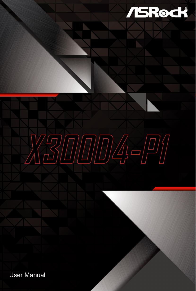
1.3 Motherboard Layout
6 7
Page 12

English
No. Description
1 Clear CMOS Jumper (CLR MOS1)
2 2 x 260-pin DDR4 SO-DIMM Slots (DDR4_A1, DDR4_B1)
3 CPU Fan Connector (CPU_FAN1)
4 2.5W Mono Out Speaker Header (MONO1)
5 SATA3 Connector (SATA1)
6 ROM Recovery Header (ROM_R)
7 Chassis Intrusion Header (CI1)
8 VGA Header (VGA1)
X300D4-P1
Page 13
English
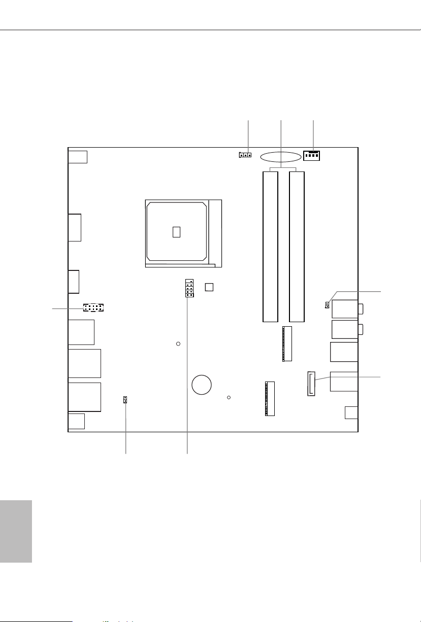
1.4 Front Panel
1
No. Description No. Description
1 Power Button (S W1) 4 USB 3.2 Gen1 Type-A Port
2 USB 3.2 Gen1 Type-A Port (USB_TA _2)
3 USB 3.2 Gen1 Type-C Port (USB_TC_2)*
* Please note that if your motherboard, with a A MD Flavor 2 or Pic asso Athlon CPU installed, is connected to
a D-Sub monitor, the USB 2.0 dev ice on this Type-C port will be detected while the USB 3.0 devic e will not be
detected.
2
3 5
(USB_TA _1) 5 USB 3.2 Gen1 Type-C Port
(USB_TC_1) 6 Microphone Input (AUDIO1)
4
7
6
7 Headphone/Headset Jack
8 9
Page 14
English
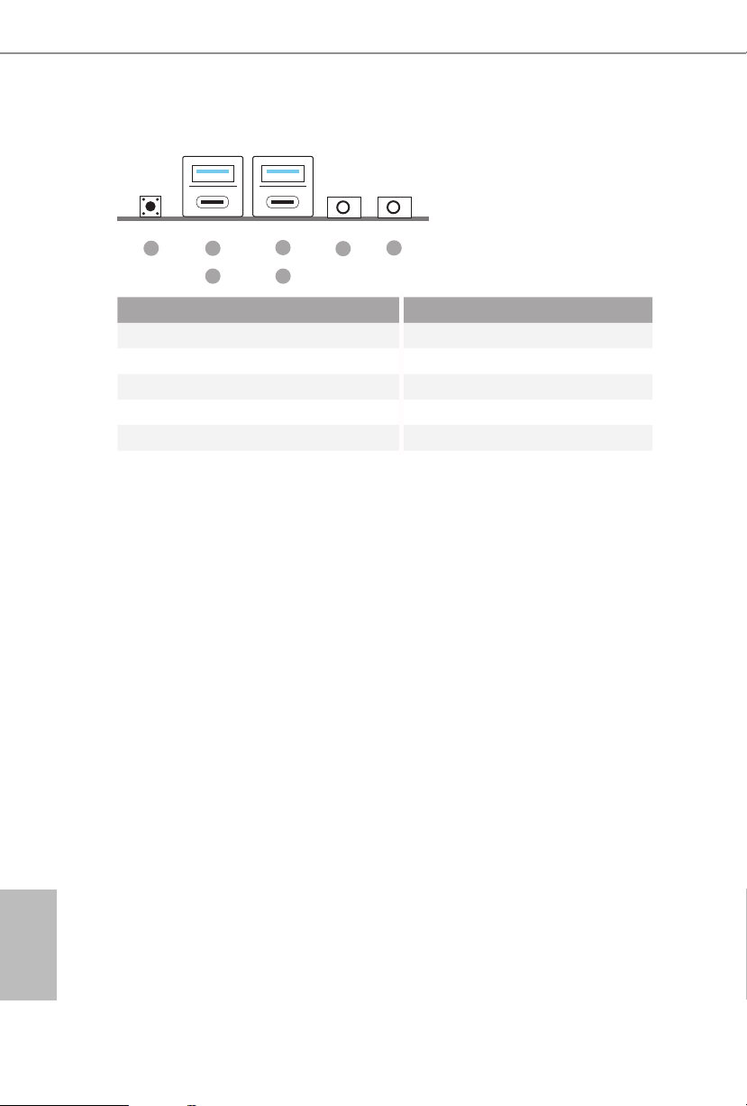
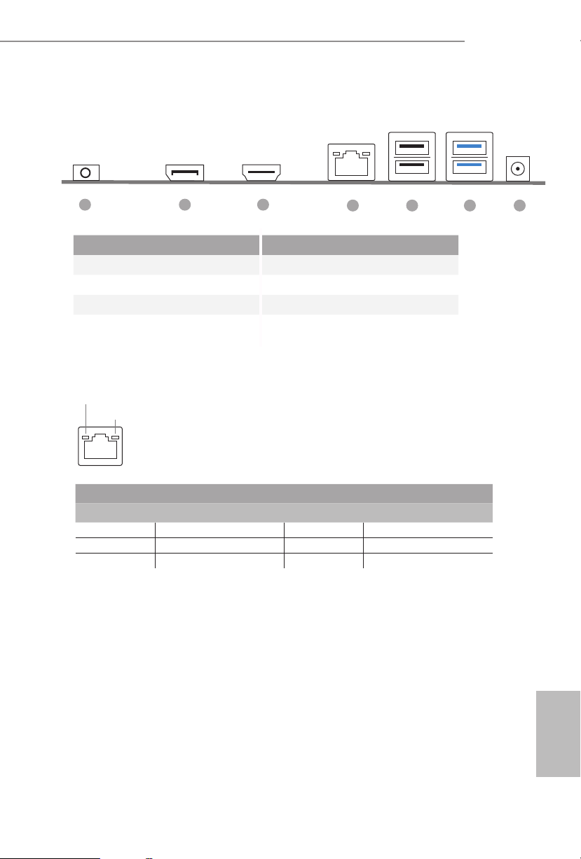
1.5 Rear Panel
X300D4-P1
1 2 3
4 5 6 7
No. Description No. Description
1 Headphone Jack 5 USB 2.0 Ports (USB_34)
2 Display Port 6 USB 3.2 Gen1 Ports
3 HDMI Port (USB_56)
4 LAN RJ-45 Port* 7 DC Jack
* ere are two LEDs on each LAN port. Please refer to the table below for the LAN port LED indications .
ACT/LINK LED
SPEED LED
LAN Por t
Activity / Link LED Speed LED
Status Description Status Description
O No Link O 10Mbps connection
Blinking Data Activity Green 100Mbps connection
On Link Orange 1Gbps connection
Page 15

English
Chapter 2 Installation
is is a Proprietary form factor motherboard. Before you install the motherboard,
study the conguration of your chassis to ensure that the motherboard ts into it.
Pre-installation Precautions
Take note of the following precautions before you install motherboard components
or change any motherboard settings.
Make sure to unplug the power cord before installing or removing the motherboard
•
components. Failure to do so may cause physical injuries and damages to motherboard
components.
In order to avoid damage from static electricity to the motherboard’s components,
•
NEVER place your motherboard directly on a carpet. Also remember to use a grounded
wrist strap or touch a safety grounded object before you handle the components.
Hold components by the edges and do not touch the ICs.
•
Whenever you uninstall any components, place them on a grounded anti-static pad or
•
in the bag that comes with the components.
When placing screws to secure the motherboard to the chassis, please do not over-
•
tighten the screws! Doing so may damage the motherboard.
10 11
Page 16
English
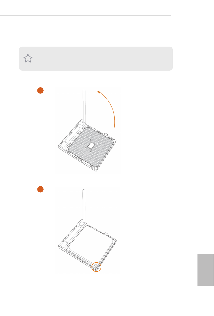
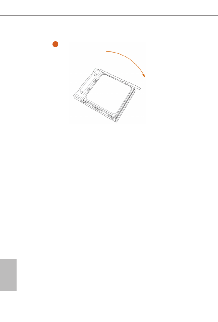
2.1 Installing the CPU
Unplug all power cables be fore installing the CPU.
1
X300D4-P1
2
Page 17
English
3
12 13
Page 18

English
2.2 Installing the CPU Fan and Heatsink
1 2
X300D4-P1
FAN
U_
CP
Page 19

English
2.3 Installing Memory Modules (SO-DIMM)
is motherboard provides two 260-pin DDR4 (Double Data Rate 4) SO-DIMM
slots.
It is not allowed to install a DDR, DDR2 or DDR3 memory module into a DDR4 slot;
otherwise , this motherboard and SO-DIMM may be damaged.
e SO-DIMM only ts in one cor rect orientation. It w ill cau se permanent damage to
the mothe rboard and the SO-DIMM if you force the SO-DIMM into the sl ot at incorrect
orientation.
1. Carefully insert the SO-DIMM memory modules into the slot at a 30-degree angle.
2. Push down until the modules snap into place.
14 15
Page 20

English
DDR4 SO-DIMM Maximum Frequency Support
Ryzen Series APUs (Renoir):
X300D4-P1
SO-DIMM Memory Slot
A1 B1
SR - 3200
- SR 3200
DR - 3200
- DR 3200
SR SR 3200
DR DR 3200
Ryzen Series CPUs (Picasso):
SO-DIMM Memory Slot
A1 B1
SR - 2933
- SR 2933
DR - 2667
- DR 2667
SR SR 2933
DR DR 2667
Frequency
(Mhz)
Frequency
(Mhz)
Page 21

English
Ryzen Series CPUs (Raven Ridge):
SO-DIMM Memory Slot
A1 B1
SR - 2933
- SR 2933
DR - 2667
- DR 2667
SR SR 2933
DR DR 2667
SR: Single rank DIMM, 1Rx4 or 1R x8 on DIMM module label
DR: Dua l ran k DIMM, 2Rx4 or 2R x8 on DIMM module label
Frequency
(Mhz)
16 17
Page 22

English
2.4 Jumpers Setup
e illustration shows how jumpers are setup. When the jumper cap is placed on
the pins, the jumper is “Short”. If no jumper cap is placed on the pins, the jumper
is “Open”. e illustration shows a 3-pin jumper whose pin1 and pin2 are “Short”
when a jumper cap is placed on these 2 pins.
Clear CMOS Jumper
(CLRMO S1)
(see p.6, No. 1)
CLRMOS1 allows you to clear the data in CMOS. To clear and reset the system
parameters to default setup, please turn o the computer and unplug the power
cord from the power supply. Aer waiting for 15 seconds, use a jumper cap to
short pin2 and pin3 on CLRMOS1 for 5 seconds. However, please do not clear the
CMOS right aer you update the BIOS. If you need to clear the CMOS when you
just nish updating the BIOS, you must boot up the system rst, and then shut it
down before you do the clear-CMOS action. Please be noted that the password,
date, time, and user default prole will be cleared only if the CMOS battery is
removed.
Default
Clear CMOS
X300D4-P1
1. e Clear CMOS Button ha s the same function as the Clear CMOS jumper.
2. If you clear the CMOS, the ca se open may be detected . Please adju st the BIOS option “Cl ear
Status” to clear the record of previous chassis intrusion status.
Page 23

English
2.5 Onboard Headers and Connectors
FAN_SPEED_CONTROL
4 3 2 1
1
Signa
MONO_OUT
MONO_OUT
1
2
Onboard headers and connectors are NOT jumpers. Do NOT place jumper caps over these
heade rs and connectors. Placing jumper caps over the headers and connectors will cause
permanent damage to the motherboard.
Serial ATA3 Connector
(SATA1:
see p.6, No. 5)
CPU Fan Connectors
(4-pin CPU_FAN1)
(see p.6, No. 3)
Chassis Intrusion Header
(2-pin CI1)
(see p.6, No. 7)
2.5W Audio Amp Output
Header
(2-pin MONO1)
(see p.6, No. 4)
GND
+12V
CPU_F
l
GND
AN_SPEED
+
-
is SATA3 connector
supports SATA data cables
for internal storage devices
with up to 6.0 Gb/s data
transfer rate.
is motherboard
provides a 4-Pin CPU fan
(Quiet Fan) connector. If
you plan to connect a 3-Pin
CPU fan, please connect it
to Pin 1-3.
is motherboard supports
CASE OPEN detection
feature that detects if the
chassis cove has been
removed. is feature
requires a chassis with
chassis intrusion detection
design.
Please connect the chassis
speaker to this header.
18 19
Page 24

English
X300D4-P1
SPI_MOS
DDC_SDA
GND
RED_VGA
ROM Recovery
Header
(8-pin ROM _R)
(see p.6, No. 6)
VGA
Header
(10 -pi n VGA 1)
(see p.6, No. 8)
SPI_CLK
SPI_DQ3
+1.8V
GRN_VGA
I
GND
GND
BLU_VGA
1
VSYNC_R
DDC_SCL
HSYNC_R
GND
RST#
SPI_DQ2
SPI_MISO
SPI_CS#
1
is ROM Recover y Connector
allows qualied technicians to
reload rmware into the SPI boot
ash in case there is problem with
the data.
is VGA Connector provides
VGA interface for your monitor.
Page 25

English
2.6 Power Button
e motherboard has one Power Button.
Power Button
(SW1)
(see p.8, No. 1)
Power Button allows users
to quickly turn on/o the
system.
20 21
Page 26

English
X300D4-P1
2.7 M.2 WiFi/BT Module Installation Guide
e M.2, also known as the Next Generation Form Factor (NGFF), is a small size and
versatile card edge connector that aims to replace mPCIe and mSATA. e M.2 Socket (Key
E) supports type 2230 WiFi/BT module.
* e M.2 socket does not support SATA M.2 SSDs.
Installing the WiFi/BT module
Step 1
Prepare a type 2230 WiFi/BT module
and the screw.
Step 2
Find the nut location to be used.
PCB Length: 3cm
Module Type: Type2230
A
Step 3
Gently insert the WiFi/BT module
into the M.2 slot. Please be aware
that the module only ts in one
orientation.
A
o
A
20
Page 27

English
Step 4
Tighten the screw with a screwdriver
to secure the module into place.
Please do not overtighten the screw as
this might damage the module.
A
22 23
Page 28

English
X300D4-P1
2.8 M.2_SSD (NGFF) Module Installation Guide (M2_1)
e Ultra M.2, a lso known as the Next Generation Form Factor (NGFF), is a small size
and versatile card edge connector that aims to replace mPCIe and mSATA. e Ultra M.2
Socket, support type 2280 M.2 SATA3 6.0 Gb/s module and M.2 PCI Express module up to
Gen3 x4 (32 Gb/s).
Installing the M.2_SSD (NGFF) Module
Step 1
Prepare a M.2_SSD (NGFF) module
and the screw.
Step 2
Gently insert the M.2 (NGFF) SSD
module into the M.2 slot. Please
be aware that the M.2 (NGFF) SSD
module only ts in one orientation.
o
20
Step3
Tighten the screw with a screwdriver
to secure the module into place.
Please do not overtighten the screw as
NUT1NUT2
this might damage the module.
Page 29

English
M.2_SSD (NGFF) Module Support List
Vendor Interface P/N
ADATA PCIe ADATA ASX8200PNP (XPG SX8200 Pro-512GB)
ADATA PCIe ADATA AS40G-256GT-C XPG SPECTRIX S40G 256G Gen3 x4
ADATA PCIe ADATA SX8100NP-512G-C SX8100NP 512G Gen3 x4
ADATA PCIe ADATA ASX6000PNP-256GT-C XPG SX6000 Pro 256G Gen3 x4
ADATA PCIe ADATA ASX8200 Pro-256G
Apacer PCIe Apacer AP240GZ280-240GB
Crucial PCIe CRUCIA L P1 SERIES-CT1000P1SSD8-1TB
Crucial PCIe CRUCIA L P1-500 G
Hikvision PCIe HIKVISION E1000N-NVMe-256G-3Y (Gen3 x2)
HP PCIe HP 5MS22AA#ABC EX950 512G Gen3 x4
Intel PCIe INTEL 660P SERIES-SSDPEKNW512G8-512G
Intel PCIe INTEL 760P-SSDPEKKW256G8-256GB
Intel PCIe INTEL SSDPEKNW020T9 665P 2TB Gen3 x4
Kingston PCIe KINGSTON A1000-SA1000M8/240G (Gen3 x2)
Kingston PCIe Kingston KC2000-250G (SKC2000M8/250G) Gen3 x4
Kingston PCIe Kingston KC1000 SKC1000-480GB
Patriot PCIe Patriot VPN100-256G (VPN100-256GM28H) Gen3 x4
Pioneer PCIe Pioneer APS-SE20G-256 (Gen3 x4
Phison PCIe PHISON H531-190409015-1T (Gen4 x4)
PLEXTOR PCIe PLEXTOR PX-512M9PEGN-512GB
PLEXTOR PCIe PLEXTOR PX-256M8SeGN-256GB
Pioneer PCIe PIONEER APS-SE10G-512 (Gen3 x2)
Samsung PCIe Sam su ng MZ -V7 P512-512GB (970PRO)
Samsung PCIe Samsung MZ-VPW1280-128GB (SM961)
Samsung PCIe Samsung MZ-V7E250-250GB 970EVO 250G Gen3 x4
Samsung PCIe Samsu ng MZ-V6E250 -250GB (960 E VO)
Samsung PCIe Samsung MZ-V7S500-MZVLB500HBJQ-500G (970EVO+)
Samsung PCIe Samsung PM981 512G Gen3 x4
Samsung PCIe Samsung MZ-VLW1280-128GB (PM961)
Seagate PCIe Seagate FireCuda 510-1TB (ZP1000GM30011)
Seagate PCIe Seagate ZP2000GM30001 FireCuda 510 2TB Gen3 x4
Seagate PCIe Seagate ZP256CM30011 BarraCuda 510 256G Gen3 x4
Seagate PCIe Seagate ZP500GM30002 FireCuda 520 500G Gen4 x4
Seagate PCIe Seagate ZP2000GM30002 FireCuda 520 2TB Gen4 x4
Seagate PCIe Seagate ZP1000CM3A001 BarraCuda 510 1TB Gen3 x4
Team PCIe Tea mTM8FP4001T-1TB Gen3 x4
Team PCIe Team TM8FP5001T0C110 T-FORCE-CARDEA II 1TB Gen3 x4
Team PCIe Team CARDEA-240GB
TOSHIBA PCIe TOSHIBA RD50500G00 RD500 500G Gen3 x4
TOSHIBA PCIe TOSHIBA THN-RC50Z5000C8 RC500 500G Gen3 x4
TOSHIBA PCIe TOSHIBA XG3-128GB
UMAX PCIe UMAX M500-HDUM500PCIE256G (Gen3 x2)
UNIC PCIe UNIC UNSPC256AKMM P5160 256G Gen3 x4
WD PCIe
24 25
WD SDAPNUW-512G-1006 (SN520) (Gen3 x2)
Page 30

English
WD PCIe WD WDS100T3X0C-00SJG0 (Black SN750-1TB)
WD PCIe WD SN500-500GB (WDS500G1B0C-00S6U0) (Gen3 x2)
ADATA SATA ADATA ASU650NS38-240GT-C SU650NS38 240G SATA3
ADATA SATA ADATA ASU800NS38-512GT-C
ADATA SATA ADATA-GAMING-XPG-SX930-ASX930S3-120GM-C-120G
ADATA SATA ADATA-ULTIMATE-SU900-ASU900SS-256GM-C-256G
Anaconda SATA ANACONDA-TS SERIES-TS240201803718-240G
Apacer SATA A PACE R-PA NTHER-AS35 0-A P12 0 GAS35 0-1-12 0G
Crucial SATA CRUCIAL MX500 SERIES-CT500MX500SSD4-500G
Crucial SATA CRUCIAL-BX500-CT120BX500SSD1-120G
Crucial SATA CRUCIAL-MX500-CT250MX500SSD1-250G
EZLink SATA ezlink P51B-80-120GB
HGST SATA HGST-HT S721010A9E630-1TB
Hikvision SATA HIKVISION-C100-HS-SSD- C100-480 G
Intel SATA INTEL-540SSERIES-SSDSCKKW240H6-240G
Intel SATA INTEL-545S SERIES-SSDSC2KW128G8X1-128G
Intel SATA INTEL-730SERIES-SSDSC2BP240G4R5-240GB
Kingston SATA Kingston SM2280S3G2/120G
Kingston SATA KINGSTON-HYPERX-FURY-RGB-SHFR200/240G-240G
Kingston SATA KINGSTON-HYPERX-SAVAGE-SHSS37A/240G
Kingston SATA KINGSTON-V300-SV300S37A-120G
KLEVV SATA KLEVV-NEO-N500-D240GAA-N500-240G
LITE-ON SATA LITE-ON-MU3-PH6-PH6-CE240-L2-240G
OCZ SATA OCZ-TRION100-TRN100-25SAT3-120G
OCZ SATA OCZ-VECTOR180-VTR180-25SAT3-120G-120G
Pioneer SATA PIONEER-APS-SL3N-APS-SL3N-120-120G
PLEXTOR SATA PLEXTOR-M6 PRO-PX-256M6PRO-256G
PLEXTOR SATA PLEXTOR-M6V-PX-256M6V-256G
Samsung SATA SAMSUNG-860EVO-MZ-76E250BW-MZ7LH250HAHQ-250G
SanDisk SATA SanDisk X400-SD8SN8U-128G
SanDisk SATA Sandisk Z400s-SD8SNAT-128G-1122
SanDisk SATA SANDISK-EXTREME PRO-SDSSDXPS-240G
SanDisk SATA SANDISK-X300-SD7SB6S-128G
Seagate SATA SEAGATE-FI RECUDA-LX015-ST1000L X015 -1T-W/8G SSD
Seagate SATA SE AGATE-ST500LM021-3Y/P-500G
Tcel l SATA TCELL-TT650-240G
Team Group SATA
TOSHIBA SATA TOSHIBA-MQ02ABD100H-MLC-NAND8G+HD1T-1T
TOSHIBA SATA TOSHIBA-Q300 PRO-H DTS412AZ STA-128G
TOSHIBA SATA TOSHIBA-Q300 -HDTS712AZSTA-120G
Tra nscend SATA Transcend TS256GMTS800-256GB
Tra nscend SATA TRANSCEND-SSD340K-TS128GSSD340K-128G
Tra nscend SATA TRANSCEND-SSD370S-TS128GSSD370S-128G
TEAM GROUP-T-FORCE-DELTA RGB-T253TR250G3C313-5V-
250G
X300D4-P1
Page 31

English
UMAX SATA UMAX-S330-HDUM330SSD240G-240G
V-Col or SATA V-Color 240G 250g
V-Col or SATA V-COLOR-VS S100-VS S100 -240G-FO-240G
WD SATA WD BLUE 3D NAND WDS500G2B0B-00YS70-500G
WD SATA WD GREEN WDS240G1G0B-00RC30-240GB
WD SATA WD WDS100T1B0B-00AS40 WD BLUE PC SSD 1TB SATA3
WD SATA WD WDS200T2B0B-00YS70-2TB SATA3
WD SATA WD-BLACK-WD7500BPKX-750G
WD SATA WD-BLUE-WD10SPZX-00Z10T0-1T
WD SATA WD-BLUE-WDS250G2B0A-00SM50-250G
WD SATA WD-GREEN-WDS120G2G0A-00JH30-120G
WD SATA WD-RED-WD10JFCX-INTELLIPOWER-1T
Wyvo SATA WYVO-APS1-SSB240GTLC4-SA-AF-240G
For the latest updates of M.2_SSD (NFGG) module support list, please visit our website for
details.
26 27
Page 32

English
Chapter 3 Software and Utilities Operation
3.1 Installing Drivers
e Support CD that comes with the motherboard contains necessary drivers and
useful utilities that enhance the motherboard’s features.
Running The Support CD
To begin using the support CD, insert the CD into your CD-ROM drive. e CD
automatically displays the Main Menu if “AUTORUN” is enabled in your computer.
If the Main Menu does not appear automatically, locate and double click on the le
“ASRSETUP.EXE” in the Support CD to display the menu.
Drivers Menu
e drivers compatible to your system will be auto-detected and listed on the
support CD driver page. Please click Install All or follow the order from top to
bottom to install those required drivers. erefore, the drivers you install can work
properly.
Utilities Menu
e Utilities Menu shows the application soware that the motherboard supports.
Click on a specic item then follow the installation wizard to insta ll it.
X300D4-P1
Page 33

English
Chapter 4 UEFI SETUP UTILITY
4.1 Introduction
is section explains how to use the UEFI SETUP UTILITY to congure your
system. You may run the UEFI SETUP UTILITY by pressing <F2> or <Del> right
aer you power on the computer, other wise, the Power-On-Self-Test (POST) will
continue with its test routines. If you wish to enter the UEFI SETUP UTILITY aer
POST, restart the system by pressing <Ctl> + <Alt> + <Delete>, or by pressing the
reset button on the system chassis. You may also restart by turning the system o
and then back on.
Becau se the UEFI soware is constantly being upd ated, the following UEFI setup screens
and descriptions are for reference purpose only, and they may not ex actly match what you
see on your screen .
4.1.1 UEFI Menu Bar
e top of the screen has a menu bar with the following selections:
Main
OC Tweaker
Advanced
Tool
H/W Monitor
Boot
Security
Exit
For setting system time/date information
For overclocking congurations
For advanced system congurations
Useful tools
Displays current hardware status
For conguring boot settings and boot priority
For security settings
Exit the current screen or the UEFI Setup Utility
28 29
Page 34

English
4.1.2 Navigation Keys
Use < > key or < > key to choose among the selections on the menu bar, and
use < > key or < > key to move the cursor up or down to select items, then
press <Enter> to get into the sub screen. You can also use the mouse to click your
required item.
Please check the following table for the descriptions of each navigation key.
Navigation Key(s) Description
X300D4-P1
+ / -
<Tab>
<PGUP>
<PGDN>
<HOME>
<END>
<F1>
<F7>
<F9>
<F10>
<F12>
<ESC>
To change option for the selected items
Switch to next function
Go to the previous page
Go to the next page
Go to the top of the screen
Go to the bottom of the screen
To display the General Help Screen
Discard changes and exit the SETUP UTILITY
Load optimal default values for all the settings
Save changes and exit the SETUP UTILITY
Print screen
Jump to the Exit Screen or exit the current screen
Page 35

English
4.2 Main Screen
When you enter the UEFI SETUP UTILITY, the Main screen will appear and
display the system overview.
30 31
Page 36

English
4.3 OC Tweaker Screen
In the OC Tweaker screen, you can set up overclocking features.
X300D4-P1
Becau se the UEFI soware is constantly being upd ated, the following UEFI setup
screens and de scriptions are for reference purpose only, and they may not exactly
match what you see on your scre en.
CPU Frequency and Voltage(VID) Change
If this item is set to [Manual], the multiplier and voltage will be set based on user selection.
Final result is depending on the CPU's capability.
CPU Core (Per CCX)
CPU Voltage
Species a custom CPU core voltage (mV), Should be combined with a custom CPU core
frequency. Power saving features for idle cores (e.g. cc6 sleep) remain active.
CCD0
CCX0 Frequency (MHz)
Use this item to adjust CCX0 Frequency.
Page 37

English
CCX1 Frequency (MHz)
Use this item to adjust CCX1 Frequency.
CCD1
CCX0 Frequency (MHz)
Use this item to adjust CCX0 Frequency.
CCX1 Frequency (MHz)
Use this item to adjust CCX1 Frequency.
SoC/Uncore OC Voltage(VID)
Specify the SoC/Uncore voltage (VDD_SOC) in mV to support memory and Innity Fabric
overclocking. VDD_SOC also determines the GPU voltage on processors with integrated
graphics. “SoC/Uncore OC Mode” needs to be enabled to force this voltage.
CLD0 VDDP Voltage Control
AMD Overclocking Setup VDDP is a voltage for the DDR4 bus signaling (PHY), and it is
derived from your DRAM Voltage (VDDIO_Mem). As a result, VDDP voltage in mV can
approach but not exceed your DRAM Voltage.
CLD0 VDDG CCD Voltage Control
AMD Overclocking Setup VDDG CCD represents voltage for the data portion of the Innity
Fabric. It is derived from the CPU SoC/Uncore Voltage (VDD_SOC). VDDG can approach
but not exceed VDD_SOC.
CLD0 VDDG IOD Voltage Control
AMD Overclocking Setup VDDG IOD represents voltage for the data portion of the Innity
Fabric. It is derived from the CPU SoC/Uncore Voltage (VDD_SOC). VDDG can approach
but not exceed VDD_SOC.
Core Performance Boost
Core Performance Boost (CPB) allows you to determine whether to enable the Core
Performance Boost (CPB) technology, a CPU performance-boost technology.
Global C-state Control
is option controls IO based C-state generation and DF C-states.
32 33
Page 38

English
Graphic Conguration
X300D4-P1
GFX Clock Frequency
is item allows you to alter the frequency for the GFX clock frequency. Aer you
alter the GFX Clock Frequency settings, make sure to adjust the GFX Core Voltage
settings.
*e adjustable range is dependent on the CPU being installed.
GFX Core Voltage
is item allows you to alter the voltage for the GFX Core Voltage.
*e adjustable range is dependent on the CPU being installed.
(Only for processor with integrated graphics)
(Only for processor with integrated graphics)
DRAM Timing Conguration
DRAM Information
DRAM Frequency
If [Auto] is selected, the motherboard will detect the memory module(s) inserted
and assign the appropriate frequency automatically. Setting DRAM Frequency can
adjust DRAM Timing.
Innity Fabric Frequency and Dividers
AMD Overclocking Setup Set Innity Fabric frequency (FCLK). Auto: FCLK =
MCLK. Manual: FCLK must be less than or equal to MCLK for best performance in
most cases. Latency penalties are incurred if FCLK and MCLK are mismatched, but
suciently high MCLK can negate or overcome this penalty.
DRAM Timing Conguration
Voltage Conguration
CPU Vcore Voltage (Oset)
Congure the voltage for the CPU Vcore (Oset).
VDDCR SOC Voltage (Oset)
Congure the voltage for the VDDCR SOC (Oset)
DRAM Voltage
Congure the voltage for the DRAM Voltage.
Performance Mode
Use this to enable or disable performance mode e default value is [Disabled].
Page 39

English
Adapter Select
Use this to select the adapter. e default value is [120W].
SMU Common Options
XFR Enhancement
Save User Default
Type a prole name and press enter to save your settings as user default.
Load User Default
Load previously saved user defaults.
Save User UEFI Setup Prole to Disk
Save current UEFI settings as an user default prole to disk.
Load User UEFI Setup Prole to Disk
Load previously saved user defaults from the disk.
34 35
Page 40

English
4.4 Advanced Screen
In this section, you may set the congurations for the following items: CPU
Conguration, Onboard Devices Conguration, Storage Conguration, ACPI
Conguration, Trusted Computing and AMD Firmware Version.
X300D4-P1
Setting wrong values in this sec tion may cause the system to malfunction.
UEFI Conguration
Full HD UEFI
When [Auto] is selected, the resolution will be set to 1920 x 1080 if the monitor
supports Full HD resolution. If the monitor does not support Full HD resolution,
then the resolution will be set to 1024 x 768. When [Disable] is selected, the
resolution will be set to 1024 x 768 directly.
Page 41

English
4.4.1 CPU Conguration
PSS Support
Use this to enable or disable the generation of ACPI_PPC, _PSS, and _PCT objects.
NX Mode
Use this to enable or disable NX mode.
SVM Mode
When this is set to [Enabled], a VMM (Virtual Machine Architecture)can utilize the
additional hardware capabilities provided by AMD-V. e default value is [Enabled].
Coniguration options: [Enabled] and [Disabled].
SMT Mode
is item can be used to disable symmetric multithreading. To re-enable SMT, a
power cycle is needed aer selecting [Auto].
Warning: S3 is not supported on systems where SMT is disabled.
IOMMU
Use this to enable or disable IOMMU. e default value of this feature is [Disabled].
TPM Switch
Use this to enable or disable AMD CPU fTPM.
36 37
Page 42

English
4.4.2 Onboard Devices Conguration
SR-IOV Support
Enable/disable the SR-IOV (Single Root IO Virtualization Support) if the system
has SR-IOV capable PCIe devices.
X300D4-P1
UMA Frame buer Size
is item allows you to set the size of the UMA frame buer.
(Only for processor with integrated graphics)
Onboard HD Audio
Enable/disable onboard HD audio. Set to Auto to enable onboard HD audio and
automatically disable it when a sound card is installed.
Restore on AC/Power Loss
Select the power state aer a power failure. If [Power O] is selected, the power will
remain o when the power recovers. If [Power On] is selected, the system will start
to boot up when the power recovers.
WAN Device
Enable/disable the onboard WAN device.
WAN Radio
Congure the WiFi module's connectivity.
Page 43

English
BT Control
Enable/disable the bluetooth.
Onboard LAN
Enable or disable the onboard network interface controller.
38 39
Page 44

English
4.4.3 Storage Conguration
SATA Controller(s)
Enable/disable the SATA controllers.
X300D4-P1
SATA M o de
AHCI: Supports new features that improve performance.
RAID: Combine multiple disk drives into a logical unit.
NVME RAID
Enable/disable RAID mode on NVMe device.
Page 45

English
4.4.4 ACPI Conguration
Suspend to RAM
It is recommended to select auto for ACPI S3 power saving.
Deep Sleep
Congure deep sleep mode for power saving when the computer is shut down.
Wake From Onboard LAN
Allow the system to be waked up by a onboard LAN.
RTC Alarm Power On
Allow the system to be waked up by the rea l time clock alarm. Set it to By OS to let
it be handled by your operating system.
40 41
Page 46

English
X300D4-P1
4.4.5 Trusted Computing
NOTE: Options var y depending on the version of your connected TPM module.
Security Device Support
Use this item to enable or disable BIOS support for security device. O.S. wi ll not show
Security Device. TCG EFI protocol and INT1A interface will not be available.
SHA-1 PCR Bank
Use this item to enable or disable SHA-1 PCR Bank.
SHA256 PCR Bank
Use this item to enable or disable SHA256 PCR Bank.
Pending Operation
Schedule an Operation for the Security Device.
NOTE: Your computer will reboot during restart in order to change State of the Device.
Platform Hierarchy
Use this item to enable or disable Platform Hierarchy.
Storage Hierarchy
Use this item to enable or disable Storage Hierarchy.
Endorsement Hierarchy
Use this item to enable or disable Endorsement Hierarchy.
Page 47

English
TPM2.0 UEFI Spec Version
Use this item to select the TCG2 spec. version supported.
e optional settings: [TCG_1_2]; [TCG_2].
[TCG_1_2]: compatible mode for Win8/Win10.
[TCG_2]: for TCG2 newer spec. compatible mode for Win10
Physical Presence Spec version
Select this item to tell OS to support PPI spec version 1.2 or 1.3. Please note that some HCK
tests might not support version 1.3.
Device Select
Use this item to select the TPM device to be supported. TPM 1.2 will restrict support to
TPM 1.2 devices. TPM 2.0 will restrict support to TPM 2.0 devices. Auto will support both
with the default set to TPM 2.0 devices. If TPM 2.0 devices are not found, TPM 1.2 devices
will be enumerated.
42 43
Page 48

English
4.4.6 AMD Firmware Version
is page shows all of AMD Firmware Version.
X300D4-P1
Page 49

English
4.5 Tools
SSD Secure Erase Tool
Use this tool to securely erase SSD.
Instant Flash
Save UEFI les in your USB storage device and run Instant Flash to update your
UEFI.
44 45
Page 50

English
4.6 Hardware Health Event Monitoring Screen
is section allows you to monitor the status of the hardware on your system,
including the parameters of the CPU temperature, motherboard temperature, fan
speed and voltage.
X300D4-P1
CPU Fan 1 Setting
Select a fan mode for CPU Fan 1, or choose Customize to set 5 CPU temperatures
and assign a respective fan speed for each temperature.
Case Open Feature
Enable or disable Case Open Feature to detect whether the chassis cover has been
removed.
Page 51

English
4.7 Security Screen
In this section you may set or change the supervisor/user password for the system.
You may also clear the user password.
Supervisor Password
Set or change the password for the administrator account. Only the administrator
has authority to change the settings in the UEFI Setup Utility. Leave it blank and
press enter to remove the password.
User Password
Set or change the password for the user account. Users are unable to change the
settings in the UEFI Setup Utility. Leave it blank and press enter to remove the
password.
Secure Boot
Enable to support Secure Boot.
46 47
Page 52

English
4.8 Boot Screen
is section displays the available devices on your system for you to congure the
boot settings and the boot priority.
Fast Boot
Fast Boot minimizes your computer's boot time. In fast mode you may not boot
from an USB storage device.
X300D4-P1
Boot From Onboard LAN
Allow the system to boot from a network instead of the local drive.
Setup Prompt Timeout
Congure the number of seconds to wait for the setup hot key.
Bootup Num-Lock
Select whether Num Lock should be turned on or o when the system boots up.
Full Screen Logo
Enable to display the boot logo or disable to show normal POST messages.
Page 53

English
CSM (Compatibility Support Module)
CSM
Enable to launch the Compatibility Support Module. Please do not disable unless
you’re running a WHCK test.
Launch PXE OpROM Policy
Select UEFI only to run those that support UEFI option ROM only. Select Legacy
only to run those that support legacy option ROM only. Select Do not launch to not
execute both legacy and UEFI option ROM.
Launch Storage OpROM Policy
Select UEFI only to run those that support UEFI option ROM only. Select Legacy
only to run those that support legacy option ROM only. Select Do not launch to not
execute both legacy and UEFI option ROM.
48 49
Page 54

English
4.9 Exit Screen
Save Changes and Exit
When you select this option the following message, “Save conguration changes
and exit setup?” will pop out. Select [OK] to save changes and exit the UEFI SETUP
UTILITY.
X300D4-P1
Discard Changes and Exit
When you select this option the following message, “Discard changes and exit
setup?” will pop out. Select [OK] to exit the UEFI SETUP UTILITY without saving
any changes.
Discard Changes
When you select this option the following message, “Discard changes?” will pop
out. Select [OK] to discard all changes.
Load UEFI Defaults
Load UEFI default values for a ll options. e F9 key can be used for this operation.
Launch EFI Shell from lesystem device
Copy shellx64.e to the root directory to launch EFI Shell.
Page 55

DECLARATION OF CONFORMITY
Per FCC Part 2 Section 2.1077(a)
Responsible Party Name: ASRock Incorporation
Address:
Phone/FaxNo:
hereby declares that the product
Product Name : Motherboard
13848 Magnolia Ave, Chino, CA91710
+1-909-590-8308/+1-909-590-1026
Model Number :
Conforms to the following specications:
FCC Part 15, Subpart B, Unintentional Radiators
Supplementary Information:
X300D4-P1
is device complies with part 15 of the FCC Rules. Operation is subject to the
following two conditions: (1) is device may not cause harmful interference,
and (2) this device must accept any interference received, including interference
that may cause undesired operation.
James
Representative Person’s Name:
Signature :
Date :
May 12, 2017
Page 56

EMC —Directive 2014/30/EU (from April 20th, 2016)
ڛ
☐
EU Declaration of Conformity
For the following equipment:
Motherboard
(Product Name)
X300D4-P1
(Model Designation / Trade Name)
☐ EN 55022:2010/AC:2011 Class B EN 55024:2010/A1:2015
ڛ EN 55032:2012+AC:2013 Class B ڛڛ EN 61000-3-3:2013
ڛ EN 61000-3-2:2014
☐
LVD —Directive 2014/35/EU (from April 20th, 2016)
EN 60950-1 : 2011+ A2: 2013 ☐
ڛ RoHS — Directive 2011/65/EU
ڛ CE marking
EN 60950-1 : 2006/A12: 2011
(EU conformity marking)
 Loading...