

Page 1

Page 2

Version 1.0
Published September 2017
Copyright©2017 ASRock INC. All rights reserved.
Copyright Notice:
No part of this documentation may be reproduced, transcribed, transmitted, or
translated in any language, in any form or by any means, except duplication of
documentation by the purchaser for backup purpose, without written consent of
ASRock Inc.
Products and corporate names appearing in this documentation may or may not
be registered trademarks or copyrights of their respective companies, and are used
only for identication or explanation and to the owners’ benet, without intent to
infringe.
Disclaimer:
Specications and information contained in this documentation are furnished for
informational use only and subject to change without notice, and should not be
constructed as a commitment by ASRock. ASRock assumes no responsibility for
any errors or omissions that may appear in this documentation.
With respect to the contents of this documentation, ASRock does not provide
warranty of any kind, either expressed or implied, including but not limited to
the implied warranties or conditions of merchantability or tness for a particular
purpose.
In no event shall ASRock, its directors, ocers, employees, or agents be liable for
any indirect, special, incidental, or consequential damages (including damages for
loss of prots, loss of business, loss of data, interruption of business and the like),
even if ASRock has been advised of the possibility of such damages arising from any
defect or error in the documentation or product.
is device complies with Part 15 of the FCC Rules. Operation is subject to the following
two conditions:
(1) this device may not cause harmful interference, and
(2) this device must accept any interference received, including interference that
may cause undesired operation.
CALIFORNIA, USA ONLY
e Lithium batter y adopted on this motherboard contains Perchlorate, a toxic substance
controlled in Perchlorate Best Management Practices (BMP) regulations passed by the
California Legislature. When you discard the Lithium battery in California, USA, please
follow the related regulations in advance.
“Perchlorate Material-special handling may apply, see www.dtsc.ca.gov/hazardouswaste/
perchlorate”
ASRock Website: http://www.asrock.com
Page 3

AUSTRALIA ONLY
Our goods come with guarantees that cannot be excluded under the Australian Consumer
Law. You are entitled to a replacement or refund for a major failure and compensation for
any other reasonably foreseeable loss or damage caused by our goods. You are also entitled
to have the goods repaired or replaced if the goods fail to be of acceptable quality and the
failure does not amount to a major failure. If you require assistance please call ASRock Tel
: +886-2-28965588 ext.123 (Standard International call charges apply)
Page 4
CE Warning
is device complies with directive 2014/53/EU issued by the Commision of the European
Community.
is equipment complies with EU radiation exposure limits set forth for an uncontrolled
environment.
is equipment should be installed and operated with minimum distance 20cm between
the radiator & your body.
Operations in the 5.15-5.35GHz band are restricted to indoor usage only.
Radio transmit power per transceiver type
Function Frequency Maximum Output Power (EIRP)
2400-2483.5 MHz 18.5 + / -1.5 dbm
5150-5250 MHz 21.5 + / -1.5 dbm
WiFi
Bluetooth 2400-2483.5 MHz 8.5 + / -1.5 dbm
5250-5350 MHz
5470-5725 MHz
18.5 + / -1.5 dbm (no TPC)
21.5 + / -1.5 dbm (TPC)
25.5 + / -1.5 dbm (no TPC)
28.5 + / -1.5 dbm (TPC)
Page 5

Contents
Chapter 1 Introduction 1
1.1 Package Contents 1
1.2 Specications 2
1.3 Motherboard Layout 7
1.4 I/O Panel 9
Chapter 2 Installation 13
2.1 Installing the CPU 14
2.2 Installing the CPU Fan and Heatsink 17
2.3 Installation of Memory Modules (DIMM) 18
2.4 Expansion Slots (PCI Express Slots) 20
2.5 Jumpers Setup 22
2.6 Onboard Headers and Connectors 23
2.7 Smart Switches 29
2.8 Dr. Debug 30
2.9 SLITM , 3-Way SLITMand Quad SLITM Operation Guide 32
2.9.1 Installing Two SLITM-Ready Graphics Cards 32
2.9.2 Installing Three SLITM-Ready Graphics Cards 34
2.9.3 Driver Installation and Setup 36
2.10 CrossFireXTM, 3-Way CrossFireXTM and Quad CrossFireXTM
Operation Guide 37
2.10.1 Installing Two CrossFireXTM-Ready Graphics Cards 37
2.10.2 Installing Three CrossFireXTM-Ready Graphics Cards 39
Page 6

2.10.3 Driver Installation and Setup 40
2.11 M.2_SSD (NGFF) Module Installation Guide 41
Chapter 3 Software and Utilities Operation 45
3.1 Installing Drivers 45
3.2 A-Tuning 46
3.2.1 Installing A-Tuning 46
3.2.2 Using A-Tuning 46
3.3 ASRock Live Update & APP Shop 49
3.3.1 UI Overview 49
3.3.2 Apps 50
3.3.3 BIOS & Drivers 53
3.3.4 Setting 54
3.4 ASRock RGB LED 55
Chapter 4 UEFI SETUP UTILITY 57
4.1 Introduction 57
4.2 EZ Mode 58
4.3 Advanced Mode 59
4.3.1 UEFI Menu Bar 59
4.3.2 Navigation Keys 60
4.4 Main Screen 61
4.5 OC Tweaker Screen 62
4.6 Advanced Screen 74
4.6.1 CPU Conguration 75
4.6.2 IIO Conguration 77
Page 7

4.6.3 Chipset Conguration 78
4.6.4 Storage Conguration 80
4.6.5 Intel® Thunderbolt™ 82
4.6.6 Super IO Conguration 83
4.6.7 ACPI Conguration 84
4.6.8 USB Conguration 85
4.6.9 Trusted Computing 86
4.7 Tools 87
4.8 Hardware Health Event Monitoring Screen 89
4.9 Security Screen 92
4.10 Boot Screen 93
4.11 Exit Screen 96
Page 8

Chapter 1 Introduction
ank you for purchasing ASRock X299 Taichi XE motherboard, a reliable
motherboard produced under ASRock ’s consistently stringent quality control.
It delivers excellent performance with robust design conforming to ASRock ’s
commitment to quality and endurance.
In this documentation, Chapter 1 and 2 contains the introduction of the
motherboard and step-by-step installation guides. Chapter 3 contains the operation
guide of the soware and utilities. Chapter 4 contains the conguration guide of
the BIOS setup.
Becau se the motherboard specication s and the BIOS soware might be updated, the
content of this documentation will be subject to change without notice. In case any modications of this d ocumentation occur, the updated version will be available on ASRock’s
website w ithout further notice . If you require technical support rel ated to this mothe rboard, please v isit our website for specic information about the model you are using. You
may nd the l atest VGA cards and CPU suppor t list on ASRock’s website as well. ASRock
website http://www.asrock.com.
X299 Taichi XE
1.1 Package Contents
ASRock X299 Taichi XE Motherboard (ATX Form Factor)
•
ASRock X299 Taichi XE Quick Installation Guide
•
ASRock X299 Taichi XE Support CD
•
1 x I/O Panel Shield
•
1 x ASRock SLI_HB_Bridge_2S Card (Optional)
•
1 x ASRock 3-Way SLI-2S1S Bridge Card (Optional)
•
4 x Serial ATA (SATA) Data Cables (Optional)
•
2 x ASRock WiFi 2.4/5 GHz Antennas (Optional)
•
3 x Screws for M.2 Sockets (Optiona l)
•
English
1
Page 9

1.2 Specications
Platform
CPU
Chipset
Memory
•
•
•
•
•
•
•
* Please note that the 4-Core processors only support Intel®
Turbo Boost Technology 2.0.
•
•
•
•
•
* e maximum memory frequency supported may vary by
processor type.
* Please refer to Memory Support List on ASRock’s website for
more information. (http://www.asrock.com/)
•
•
•
•
ATX Form Factor
8 Layer PCB
2oz Copper PCB
Supports Intel® CoreTM X-Series Processor Family for the
LGA 2066 Socket
Digi Power design
13 Power Phase design
Supports Intel® Turbo Boost Max Technology 3.0
Supports ASRock Hyper BCLK Engine III
Intel® X299
Quad Channel DDR4 Memory Technology
8 x DDR4 DIMM Slots
Supports DDR4 4 400+(OC)*/4266(OC)/4133(OC)/40 00
(OC)/3866(OC)/3800(OC)/3733(OC)/3600(OC)/3200(OC)/2
933(OC)/2800(OC)/2666/2400/2133 non-ECC, un-buered
memory
Supports non-ECC RDIMM (Registered DIMM)
Max. capacity of system memor y: 128GB
Supports Intel® Extreme Memory Prole (XMP) 2.0
15μ Gold Contact in DIMM Slots
English
2
Expansion
Slot
4 x PCI Express 3.0 x16 Slots*
•
* If you install CPU with 44 lanes, PCIE1/PCIE2/PCIE3/PCIE5
will run at x16/x8/x16/x0 or x8/x8/x16/x8.
* If you install CPU with 28 lanes, PCIE1/PCIE2/PCIE3/PCIE5
will run at x16/x0/x8/x0 or x8/x0/x8/x8.
* If you install CPU with 16 lanes, PCIE1/PCIE2/PCIE3/PCIE5
will run at x16/x0/x0/x0 or x8/x0/x4/x0.
* Supports NVMe SSD as boot disks
Page 10

Audio
1 x PCI Express 2.0 x1 Slot
•
Supports AMD Quad CrossFireXTM, 3-Way CrossFireXTM
•
and CrossFireXTM **
** 3-Way CrossFireXTM is only supported with CPU with 44
lanes or 28 lanes.
Supports NVIDIA® Quad SLITM, 3-Way SLITM and SLITM***
•
*** is feature is only supported with CPU with 44 lanes or 28
lanes.
1 x Vertical M.2 Socket (Key E) with the bundled WiFi-
•
802.11ac module (on the rear I/O)
15μ Gold Contact in VGA PCIe Slot (PCIE1 and PCIE3)
•
7.1 CH HD Audio with Content Protection (Realtek
•
ALC1220 Audio Codec)
Premium Blu-ray Audio support
•
Supports Surge Protection (ASRock Full Spike Protection)
•
Supports Purity SoundTM 4
•
- Nichicon Fine Gold Series Audio Caps
- 120dB SNR DAC with Dierential Amplier
- NE5532 Premium Headset Amplier for Front Panel
Audio Connector (Supports up to 600 Ohm headsets)
- Pure Power-In
- Direct Drive Technology
- PCB Isolate Shielding
- Impedance Sensing on Line Out port
- Individual PCB Layers for R/L Audio Channel
- Gold Audio Jacks
- 15μ Gold Audio Connector
Supports DTS Connect
•
X299 Taichi XE
LAN
Gigabit LAN 10/100/100 0 Mb/s
•
1 x Giga PHY Intel® I219V, 1 x GigaLAN Intel® I211AT
•
Supports Wake-On-LAN
•
Supports Lightning/ESD Protection
•
Supports Dual LAN with Teaming*
•
* Teaming is supported on Windows® 10 RS2 and above.
Supports Energy Ecient Ethernet 802.3az
•
Supports PXE
•
English
3
Page 11

Wireless
LAN
Rear Panel
I/O
Intel® 802.11ac WiFi Module
•
Supports IEEE 802.11a/b/g/n/ac
•
Supports Dual-Band (2.4/5 GHz)
•
Supports high speed wireless connections up to 433Mbps
•
Supports Bluetooth 4.2 / 3.0 + High speed class II
•
2 x Antenna Ports
•
1 x PS/2 Mouse/Keyboard Port
•
1 x Optical SPDIF Out Port
•
2 x USB 2.0 Ports (Supports ESD Protection)
•
1 x USB 3.1 Gen2 Type-A Port (10 Gb/s) (ASMedia ASM3142)
•
(Supports ESD Protection (ASRock Full Spike Protection))
1 x USB 3.1 Gen2 Type-C Port (10 Gb/s) (ASMedia ASM3142)
•
(Supports ESD Protection (ASRock Full Spike Protection))
* Ultra USB Power is supported on USB3_12 ports.
* ACPI wake-up function is not supported on USB3_12 ports.
4 x USB 3.1 Gen1 Ports (Supports ESD Protection (ASRock
•
Full Spike Protection))
2 x RJ-45 LAN Ports with LED (ACT/LINK LED and SPEED
•
LED)
1 x BIOS Flashback Button
•
1 x Clear CMOS Button
•
HD Audio Jacks: Rear Speaker / Central / Bass / Line in /
•
Front Speaker / Microphone (Gold Audio Jacks)
English
4
Storage
8 x SATA3 6.0 Gb/s Connectors, support RAID (RAID 0,
•
RAID 1, RAID 5, RAID 10, Intel Rapid Storage Technology
15 and Intel Smart Response Technology), NCQ, AHCI and
Hot Plug*
* If M2_1 is occupied by a SATA-type M.2 device, SATA3_1 will
be disabled.
* If M2_2 is occupied by a SATA-type M.2 device, SATA3_0 will
be disabled.
* If M2_3 is occupied by a SATA-type M.2 device, SATA3_7
will be disabled.
2 x SATA3 6.0 Gb/s Connectors by ASMedia ASM1061, sup-
•
port NCQ, AHCI and Hot Plug
1 x Ultra M.2 Socket (M2_2), supports M Key type
•
2230/2242/2260/2280/22110 M.2 SATA3 6.0 Gb/s module
and M.2 PCI Express module up to Gen3 x4 (32 Gb/s)**
Page 12

Connector
X299 Taichi XE
2 x Ultra M.2 Sockets (M2_1 and M2_3), support M Key
•
type 2230/2242/2260/2280 M.2 SATA3 6.0 Gb/s module and
M.2 PCI Express module up to Gen3 x4 (32 Gb/s)**
** Supports Intel® OptaneTM Technology (on M2_2 and M2_3)
** Supports NVMe SSD as boot disks
** Supports ASRock U.2 Kit
1 x Virtual RAID On CPU Header
•
1 x TPM Header
•
1 x Power LED and Speaker Header
•
2 x RGB LED Headers
•
* Support up to 12V/3A, 36W LED Strip
1 x CPU Fan Connector (4-pin)
•
* e CPU Fan Connector supports the CPU fan of maximum
1A (12W) fan power.
1 x CPU Optional/Water Pump Fan Connector (4-pin)
•
(Smart Fan Speed Control)
* e CPU Optional/Water Pump Fan supports the water cooler
fan of maximum 1.5A (18W) fan power.
2 x Chassis Fan Connectors (4-pin) (Smart Fan Speed Con-
•
trol)
1 x Chassis Optional/Water Pump Fan Connector (4-pin)
•
(Smart Fan Speed Control)
* e Chassis Optional/Water Pump Fan supports the water
cooler fan of maximum 1.5A (18W) fan power.
* CPU_OPT/W_PUMP, CHA_FAN1, CHA_FAN2 and CHA_
FAN3/W_PUMP can auto detect if 3-pin or 4-pin fan is in use.
1 x 24 pin ATX Power Connector (Hi-Density Power
•
Connec tor)
2 x 8 pin 12V Power Connectors (Hi-Density Power
•
Connec tor)
1 x Front Panel Audio Connector (15μ Gold Audio Connec-
•
tor)
1 x underbolt AIC Connector (5-pin)
•
* e underbolt™ AIC card can be installed in the enabled
PCIe slot (depending on CPU type).
2 x USB 2.0 Headers (Support 4 USB 2.0 ports) (Supports
•
ESD Protection (ASRock Full Spike Protection))
2 x USB 3.1 Gen1 Headers (Support 4 USB 3.1 Gen1 ports)
•
(ASMedia ASM1074 Hub) (Supports ESD Protection (AS-
Rock Full Spike Protection))
English
5
Page 13

BIOS
Feature
Hardware
Monitor
OS
1 x Dr. Debug with LED
•
2 x AMI UEFI Legal BIOS with multilingual GUI support (1
•
x Main BIOS and 1 x Backup BIOS)
Supports Secure Backup UEFI Technology
•
ACPI 6.1 Compliant wake up events
•
SMBIOS 3.0 Support
•
CPU, DRAM, VPPM, VTTM, PCH 1.0V, VCCMPHY,
•
VCCIO, VCCST, VCCSA, VCCSFR, VCCPLL, CLK VDD
Voltage Multi-adjustment
Temperature Sensing: CPU, CPU Optional/Water Pump,
•
Chassis, Chassis Optional/Water Pump Fans
Fan Tachometer: CPU, CPU Optional/Water Pump, Chassis,
•
Chassis Optional/Water Pump Fans
Quiet Fan (Auto adjust chassis fan speed by CPU tempera-
•
ture): CPU, CPU Optional/Water Pump, Chassis, Chassis
Optional/Water Pump Fans
Fan Multi-Speed Control: CPU, CPU Optional/Water Pump,
•
Chassis, Chassis Optional/Water Pump Fans
Voltage monitoring: +12V, +5V, +3.3V, CPU Vcore, DRAM,
•
PCH 1.0V, VCCIO, VCCSA, VCCSFR
Microso® Windows® 10 64-bit
•
English
6
FCC, CE
Certications
* For detailed product infor mation, please visit our website: http://www.asrock .com
Please realize that there is a certain risk involved with overclocking, including adjusting
the setting in the BIOS, applying Untied Overclocking Technology, or using third-party
overclocking tools. Overclocking may aect your system’s stability, or even cause damage to
the components and devices of your system. It should be done at your own risk and expense.
We are not responsible for possible damage caused by overclocking.
•
ErP/EuP ready (ErP/EuP ready power supply is required)
•
Page 14
ATXP WR 1
Ult ra M.2
PCIe Ge n3 x4
RGB_LED2
1
Intel
X299
ATX12V1
LAN
LAN
PCIE1
Top:
Central/Bass
Center:
REAR SPK
Top:
LINE IN
Center:
FRONT
Bottom:
Optical
SPDIF
Bottom:
MIC IN
PCIE3
HDLED RESET
PLED PWRBTN
PANEL1
1
1
HD_AUDIO1
PCIE5
SATA3_2_3
SATA3_4_5
PCIE4
CPU_FAN1
RoHS
9
8
10
13
14
15
SATA3_6_7
16
2223
21
29
28
BIOS
_FB1
SATA3_0_1
4
7
DDR4 _B2 (64 b it, 288 -pin mo dule)
DDR4 _B1 (64 b it, 288 -pin mo dule)
DDR4 _A2 (64 b it, 288 -pin mo dule)
DDR4 _A1 (64 b it, 288 -pin mo dule)
2
1
24
20
BIOS_A1
BIOS
1
TPMS1
CLRMOS1
1
M2_WIFI_1
CHA_FAN1
CHA_FAN2
27
30
DDR4 _C1 (64 b it, 288 -pin mo dule)
DDR4 _C2 (64 b it, 288 -pin mo dule)
DDR4 _D1 (64 b it, 288 -pin mo dule)
DDR4 _D2 (64 b it, 288 -pin mo dule)
6
5
BIOS_A_LED1
2066 Socket
USB3_7_ 8
Dr.
Debug
USB 2.0
T: USB1
B: USB2
PS2
Keybo ard
/Mous e
1
SPK_PLED1
M2_3
M2_2
SATA3_A1_ A2
17
11
1
1
USB3_5_ 6
12
18
19
T B1
1
RGB_LED1
1
25
PCIE2
BIOS_B1
BIOS
CHA_FAN3/
W_PUMP
BIOS_B_LED1
X299 Taichi XE
Purity
Sound 4
TM
CLRC
BTN1
Top:
RJ-45
Top:
RJ-45
USB 3.1 Gen1
T: USB3
B: USB4
USB 3.1 Gen2
T: USB31_TA_1
B: USB31_TC_1
Top:
RJ-45
USB 3.1 Gen1
T: USB1
B: USB2
ATX12V2
3
USB3_4
1
1
USB5_6
VROC1
1
26
CPU_OPT/
W_PUMP
M2_1
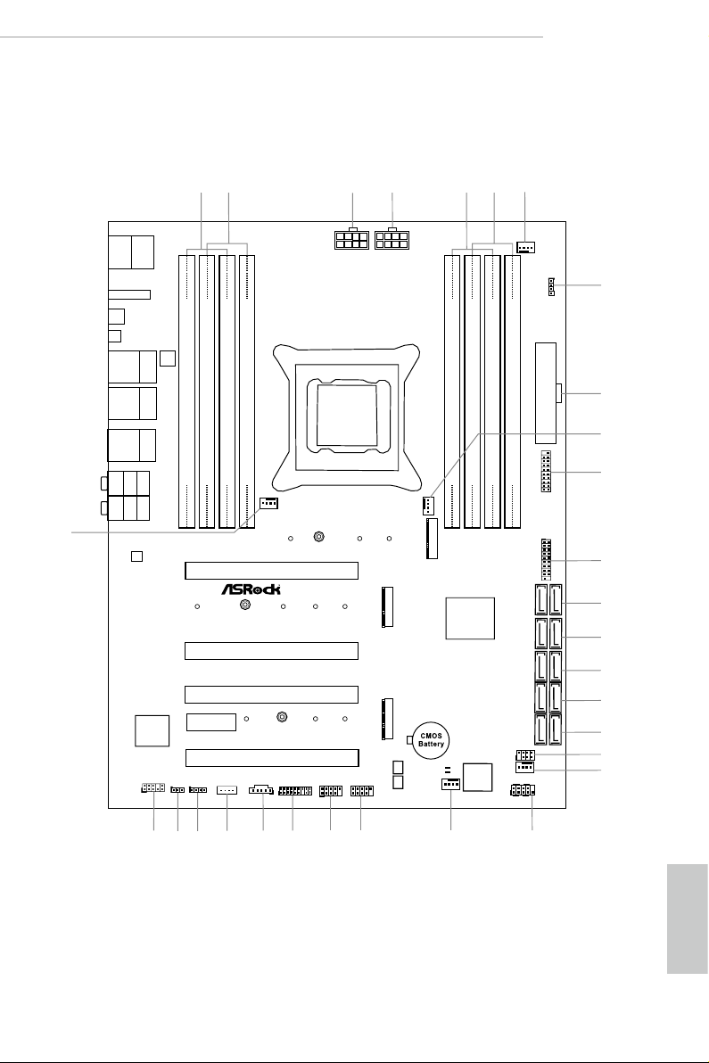
1.3 Motherboard Layout
X299 Taichi XE
English
7
Page 15

English
No. Description
1 2 x 288-pin DDR4 DIMM Slots (DDR4_A1, DDR4_B1)
2 2 x 288-pin DDR4 DIMM Slots (DDR4_A2, DDR4_B2)
3 ATX 12V Power Connector (ATX12V2)
4 ATX 12V Power Connector (ATX12V1)
5 2 x 288-pin DDR4 DIMM Slots (DDR4_C2, DDR4_D2)
6 2 x 288-pin DDR4 DIMM Slots (DDR4_C1, DDR4_D1)
7 CPU Fan Connector (CPU_FAN1)
8 RGB LED Header (RGB_LED2)
9 ATX Power Connector (ATXPWR1)
10 CPU Fan / Waterpump Fan Connector (CPU_OPT/W_PUMP)
11 USB 3.1 Gen1 Header (USB3_7_8)
12 USB 3.1 Gen1 Header (USB3_5_6)
13 SATA3 Connectors (SATA3_0_1)
14 SATA3 Connectors (SATA3_2_3)
15 SATA3 Connectors (SATA3_4_5)
16 SATA3 Connectors (SATA3_6_7)
17 SATA3 Connectors (SATA3_A1_A2)
18 Power LED and Speaker Header (SPK_PLED1)
19 Chassis Fan Connector (CHA_FAN1)
20 System Panel Header (PANEL1)
21 Chassis Fan / Waterpump Fan Connector (CHA_FAN3/W_PUMP)
22 USB 2.0 Header (USB5_6)
23 USB 2.0 Header (USB3_4)
24 TPM Header (TPMS1)
25 underbolt AIC Header (TB1)
26 Virtual RAID On CPU Header (VROC1)
27 RGB LED Header (RGB_LED1)
28 Clear CMOS Jumper (CLR MOS1)
29 Front Panel Audio Header (HD_AUDIO1)
30 Chassis Fan Connector (CHA_FAN2)
8
Page 16
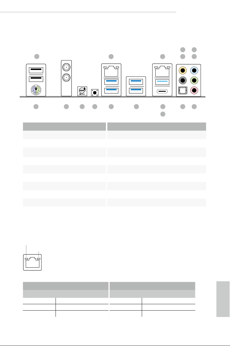
1.4 I/O Panel
11
6
X299 Taichi XE
1
17 14
No. Description No. Description
1 USB 2.0 Port (USB12) 10 USB 3.1 Gen2 Type-A Port (USB31_TA_1)
2 LAN RJ-45 Port (Intel® I211AT)* 11 USB 3.1 Gen2 Type-C Port (USB31_TC_1)
3 LAN RJ-45 Port (Intel® I219V)* 12 USB 3.1 Gen1 Ports (USB3_34)
4 Central / Bass (Orange) 13 USB 3.1 Gen1 Ports (USB3_12)***
5 Rear Speaker (Black) 14 Clear CMOS Button
6 Line In (Light Blue) 15 Flashback Button
7 Front Speaker (Lime)** 16 Antenna Ports
8 Microphone (Pink) 17 PS/2 Mouse/Keyboard Port (PS2 _KB1)
9 Optical SPDIF Out Port
1516 1213
2 3
547
8910
* ere are two LEDs on each LAN port. Please refer to the table below for the LAN port LED indications.
ACT/LINK LED
SPEED LED
LAN Por t
Activity / Link LED Speed LED
Status Description Status Description
O No Link O 10Mbps connection
Blinking Data Activity Orange 100Mbps connection
On Link Green 1Gbps connection
English
9
Page 17

** If you use a 2- channel speaker, please connect the speaker’s plug into “Front Speaker Jack”. See the table below
for connection details in accordance with the type of s peaker you use.
Audio Output
Channels
Front Speaker
(No. 7)
Rear Speaker
(No. 5)
Central / Bass
(No. 4)
2 V -- -- --
4 V V -- --
6 V V V --
8 V V V V
*** ACPI wake-up function is not supported on USB3_12 ports.
To enable Multi-Streaming, you need to connect a front panel audio cabl e to the front
panel audio header. Aer restarting your computer, you will nd the “Mixer” tool on your
system. Please select “Mixer ToolBox” , click “Enable playback multi-streaming”, and
click “ok”. Choose “2CH”, “4CH”, “6CH”, or “8CH” and then you are allowed to select
“Realtek HDA Primary output” to use the Rear Speaker, Central/Bass, and Front Speaker,
or select “Realtek HDA Audio 2nd output” to use the front panel audio.
Line In
(No. 6)
English
10
Page 18

X299 Taichi XE
1.5 WiFi-802.11ac Module and ASRock WiFi 2.4/5 GHz Antenna
WiFi-802.11ac + BT Module
is motherboard comes with an exclusive WiFi 802.11 a/b/g/n/ac + BT v4.2
module (pre-installed on the rear I/O panel) that oers support for WiFi 802.11 a/b/
g/n/ac connectivity standards and Bluetooth v4.2. WiFi + BT module is an easy-to-
use wireless local area network (WLAN) adapter to support WiFi + BT. Bluetooth
v4.2 standard features Smart Ready technology that adds a whole new class of
functionality into the mobile devices. BT 4.2 also includes Low Energy Technology
and ensures extraordinary low power consumption for PCs.
* e transmission speed may vary according to the environment.
11
English
Page 19
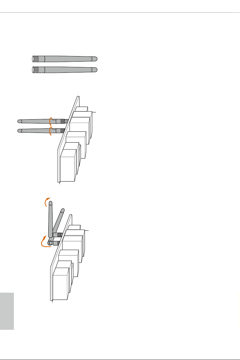
WiFi Antennas Installation Guide
Step 1
Prepare the WiFi 2.4/5 GHz Antennas that come
with the package.
Step 2
Connect the two WiFi 2.4/5 GHz Antennas to
the antenna connectors. Turn the antenna clock-
wise until it is securely connected.
Step 3
Set the WiFi 2.4/5 GHz Antenna as shown in the
illustration.
*You may need to adjust the direction of
the antenna for a stronger signal.
English
12
Page 20

Chapter 2 Installation
is is an ATX form factor motherboard. Before you install the motherboard, study
the conguration of your chassis to ensure that the motherboard ts into it.
Pre-installation Precautions
Take note of the following precautions before you install motherboard components
or change any motherboard settings.
Make sure to unplug the power cord before installing or removing the motherboard
•
components. Failure to do so may cause physical injuries and damages to motherboard
components.
In order to avoid damage from static electricity to the motherboard’s components,
•
NEVER place your motherboard directly on a carpet. Also remember to use a grounded
wrist strap or touch a safety grounded object before you handle the components.
Hold components by the edges and do not touch the ICs.
•
Whenever you uninstall any components, place them on a grounded anti-static pad or
•
in the bag that comes with the components.
When placing screws to secure the motherboard to the chassis, please do not over-
•
tighten the screws! Doing so may damage the motherboard.
X299 Taichi XE
13
English
Page 21

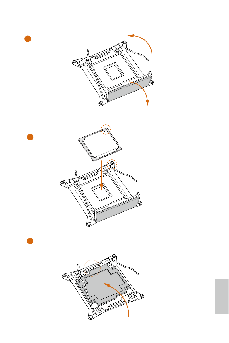
2.1 Installing the CPU
1. Before you insert the 2066-Pin CPU into the socket, plea se check if the PnP ca p is on the
socket, if the CPU surface is unclean, or if there are any bent pins in the socket. Do not
force to in sert the CPU into the socket if above situation is found. Otherwise, the CPU
will be seriously damaged.
2. Unplug all power cables before installing the CPU.
CAU TION:
Please note that X299 platform is only compatible with the LGA 2066 socket, which is
incompatible with the LGA 2011-3 socket (for X99 platform).
1
A
B
English
14
A
2
B
Page 22
X299 Taichi XE
3
4
A
B
5
English
15
Page 23
6
A
B
7
A
B
English
16
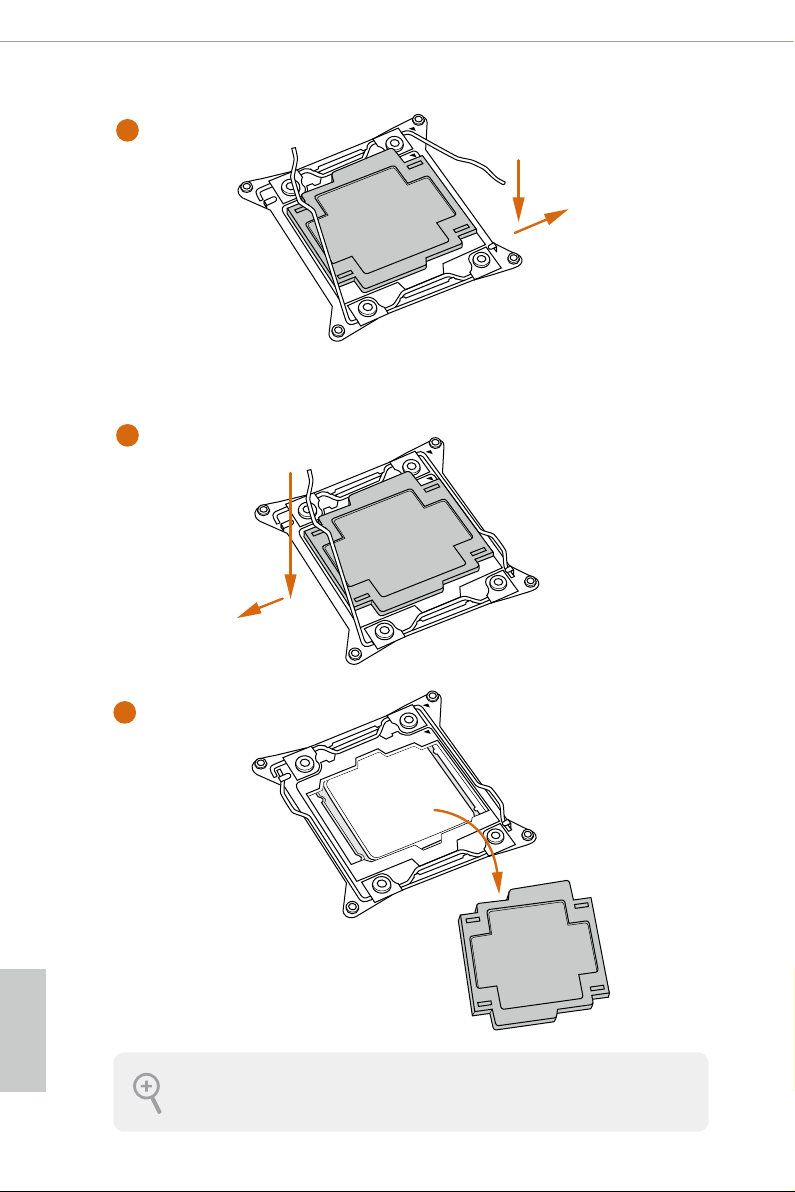
8
Please save and replace the cover if the processor is removed. e cover must be placed if
you wish to return the motherboard for aer service.
Page 24
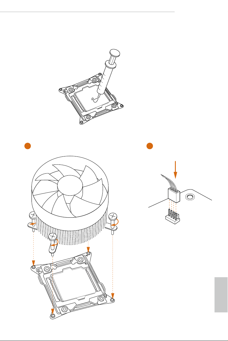
2.2 Installing the CPU Fan and Heatsink
1 2
X299 Taichi XE
FAN
CPU_
English
17
Page 25

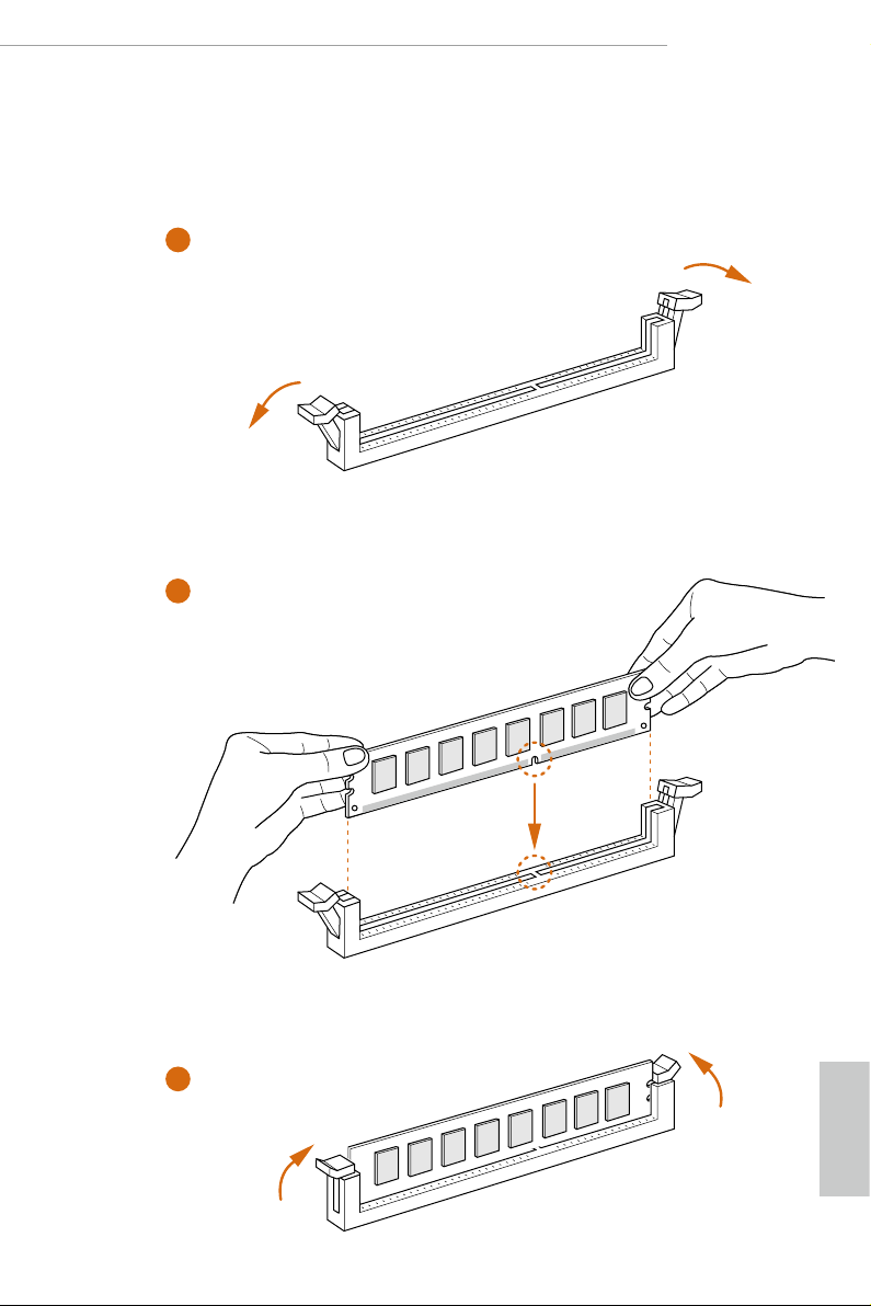
2.3 Installation of Memory Modules (DIMM)
is motherboard provides eight 288-pin DDR4 (Double Data Rate 4) DIMM slots, and
supports Quad Channel Memory Technology.
1. For quad channel conguration, you always need to install identical (the same brand,
speed , size and chip-type) DDR4 DIMM pairs.
2. It is not allowed to install a DDR, DDR2 or DDR 3 memory modul e into a DDR4 slot;
otherwise, this motherboard and DIMM may be damaged.
3. e DIMM only ts in one correct orientation . It will cause per manent damage to the
motherboard and the DIMM if you force the DIM M into the slot at incorrect orientation.
Quad Channel Memory Conguration (For CPU with 44 or 28 PCIe lanes)
Priority 1 2
DDR4_B1
DDR4_B2
DDR4_A1
DDR4_A2
DDR4_D1
DDR4_D2
DDR4_C1
DDR4_C2
Populated Populated
Populated
Populated Populated
Populated
Populated Populated
Populated
Populated Populated
Populated
English
18
Dual Channel Memory Conguration (For CPU with 16 PCIe lanes)
Priority 1 2
DDR4_D1
DDR4_D2
DDR4_C1
DDR4_C2
Due to Intel® CPU spec denition, please install the memory modules on DDR4_A1,
•
DDR4_B1, DDR4_C1 and DDR4_D1 for rst priority. If the four DDR4 DIMM slots
above are fully installed, and you want to use more than four memory modules, please
install the other memory modules from le to right (from DDR4_A2, DDR4_B2,
DDR4_D2 to DDR4_C2.)
If only two memory modules are installed in the DDR4 DIMM slots, then Dual
•
Channel Memory Technology is activated. If three memor y modules are installed, then
Triple Channel Memory Technology is activated. If more than four memory modules
are installed in the DDR4 DIMM slots, then Quad Channel Memory Technology is
activated.
Populated Populated
Populated
Populated Populated
Populated
Page 26
For CPU with 16 PCIe lanes, please install the memory modules on DDR4_C1, C2, D1
•
and D2 only.
1
2
X299 Taichi XE
3
English
19
Page 27

2.4 Expansion Slots (PCI Express Slots)
ere are 5 PCI Express slots on the motherboard.
Before installing an expansion card, please mak e sure that the power supply is switched o
or the power cord is unplugged. Please read the documentation of the expansion card and
make necessary hardware settings for the card before you start the installation.
PCIe slots:
PCIE1 (PCIe 3.0 x16 slot) is used for PCI Express x16 lane width graphics cards.
PCIE2 (PCIe 3.0 x16 slot) is used for PCI Express x8 lane width graphics cards.
PCIE3 (PCIe 3.0 x16 slot) is used for PCI Express x16 lane width graphics cards.
PCIE4 (PCIe 2.0 x1 slot) is used for PCI Express x1 lane width cards.
PCIE5 (PCIe 3.0 x16 slot) is used for PCI Express x8 lane width graphics cards.
* If you install CPU with 44 lanes, PCIE1/PCIE2/PCIE3/PCIE5 will run at x16/x8/
x16/x0 or x8/x8/x16/x8.
* If you install CPU with 28 lanes, PCIE1/PCIE2/PCIE3/PCIE5 will run at x16/x0/
x8/x0 or x8/x0/x8/x8.
* If you install CPU with 16 lanes, PCIE1/PCIE2/PCIE3/PCIE5 will run at x16/x0/
x0/x0 or x8/x0/x4/x0.
PCIe Slot Congurations (For CPU with 44 PCIe lanes)
PCIE1 PCIE2 PCIE3 PCIE4 PCIE5 M2 _1
English
20
Single Graphics Card x16 N/A N/A N/A N/A x4
Two Graphics Cards in
CrossFireXTM or SLITM
Mode
ree Graphics Cards in
3-Way CrossFireXTM Mode
or 3-Way SLITM Mode
x16 N /A x16 N/A N/A x4
x8 N/A x16 N /A x8 x4
Page 28

X299 Taichi XE
PCIe Slot Congurations (For CPU with 28 PCIe lanes)
PCIE1 PCIE2 PCIE3 PCIE4 PCIE5 M2 _1
Single Graphics Card x16 N/A N /A N/A N/A x4
Two Graphics Cards in
CrossFireXTM or SLITM
Mode
ree Graphics Cards in
3-Way CrossFireXTM Mode
or 3-Way SLITM Mode
x16 N /A x8 N/A N/A x4
x8 N/A x8 N/A x8 x4
PCIe Slot Congurations (For CPU with 16 PCIe lanes)
PCIE1 PCIE2 PCIE3 PCIE4 PCIE5 M2 _1
Single Graphics Card x16 N/A N /A N/A N/A x0
Two Graphics Cards in
CrossFireXTM Mode
For a better thermal environment , please connect a chassis fan to the motherboard’s |
chassis fan connector (CHA_FAN1, CHA_FAN2 or CHA_FAN3) when using multiple
graphics cards .
* If you install CPU with 44 or 28 lanes and encounter CrossFire issues, please
do the followings.
1. Enter UEFI by pressing <F2> or <Del> during system startup.
2. Select “Boot > CSM” from the menu.
3. Set "Launch Storage OpROM policy" to "UEFI only".
4. Press F10 to Save and Exit.
x8 N/A x4 N/A N/A x4
English
21
Page 29
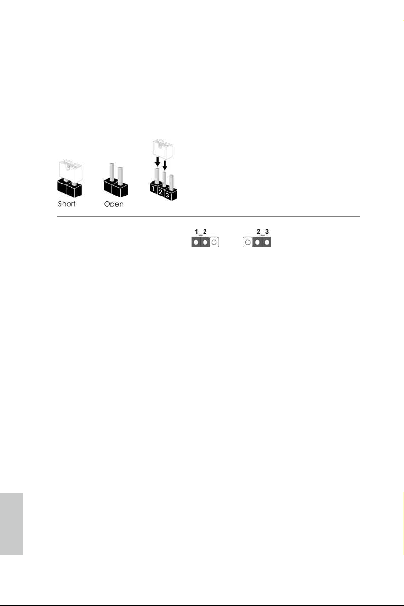
2.5 Jumpers Setup
e illustration shows how jumpers are setup. When the jumper cap is placed on
the pins, the jumper is “Short”. If no jumper cap is placed on the pins, the jumper
is “Open”. e illustration shows a 3-pin jumper whose pin1 and pin2 are “Short”
when a jumper cap is placed on these 2 pins.
Clear CMOS Jumper
(CLR MOS1)
(see p.7, No. 28)
CLRMOS1 allows you to clear the data in CMOS. To clear and reset the system
parameters to default setup, please turn o the computer and unplug the power
cord from the power supply. Aer waiting for 15 seconds, use a jumper cap to
short pin2 and pin3 on CLRMOS1 for 5 seconds. However, please do not clear the
CMOS right aer you update the BIOS. If you need to clear the CMOS when you
just nish updating the BIOS, you must boot up the system rst, and then shut it
down before you do the clear-CMOS action. Please be noted that the password,
date, time, and user default prole will be cleared only if the CMOS battery is
removed.
Clear CMOSDefault
English
22
Page 30

2.6 Onboard Headers and Connectors
1
Onboard headers and connectors are NOT jumpers. Do NOT place jumper caps over these
heade rs and connectors. Plac ing jumper caps over the hea ders and connectors will cause
permanent damage to the motherboard.
X299 Taichi XE
System Panel Header
(9-p in PA NE L1)
(see p.7, No. 20)
PWRBTN (Power But ton):
Connec t to the power button on the chassis f ront panel. You may congure the way to turn
o your system using the powe r button.
RESET (Reset Button):
Connec t to the reset button on the chassis f ront panel. Pre ss the reset button to restart the
computer if the computer freezes and fails to perform a normal restart.
PLED (Syste m Power LED):
Connec t to the power status indicator on the chassi s front panel. e LED is on when the
system is operating. e LED keeps blinking when the system is in S1/S3 sleep state. e
LED is o when the system is in S4 sleep state or powered o (S5).
HDLED (Ha rd Drive Activity LED):
Connec t to the hard drive activity LED on the chassis f ront panel. e LED is on when the
hard drive is reading or writing data .
e front panel design may dier by chassis . A front panel module mainly consists of powe r
button, reset button, power LED, hard drive a ctivity LED, speaker and etc. When connecting your chassis front panel module to this header, make sure the wire assig nments and the
pin assignments are matched correctly.
PLED+
PLED-
HDLED-
HDLED+
PWRBTN#
GND
RESET#
GND
GND
Connect the power
button, reset button and
system status indicator on
the chassis to this header
according to the pin
assignments below. Note
the positive and negative
pins before connecting
the cables.
English
23
Page 31

Power LED and Speaker
1
+5V
DUMMY
PLED+
PLED+
PLED-
DUMMY
SPEAKER
DUMMY
GND
GND
P+
P-
USB_PWR
P+
P-
USB_PWR
1
1
IntA_PB_SSTX+
IntA_PB_SSRX+
A_SSRX+
A_SSTX+
Header
(7-pin SPK_PLED1)
(see p.7, No. 18)
Please connect the
chassis power LED and
the chassis speaker to this
header.
Serial ATA3 Connectors
(SATA3_0_1:
see p.7, No. 13)
(SATA3_2_3:
see p.7, No. 14)
(SATA3_4_5:
see p.7, No. 15)
(SATA3_6_7:
see p.7, No. 16)
(SATA3_A1_A2:
see p.7, No. 17)
USB 2.0 Headers
(9-pin USB3_4)
(see p.7, No. 23)
(9-pin USB5_6)
(see p.7, No. 22)
SATA3_0
SATA3_2
SATA3_4
SATA3_6
SATA3_A1
ese ten SATA3
connectors support SATA
data cables for interna l
SATA3_1
storage devices with up to
6.0 Gb/s data transfer rate.
SATA3_3
* To minimize the boot
time, use Intel® X299
SATA ports (SATA3_0~7)
SATA3_5
for your bootable devices.
* If M2_1 is occupied by
a SATA-type M.2 device,
SATA3_7
SATA3_1 will be disabled.
* If M2_2 is occupied by
a SATA-type M.2 device,
SATA3_0 will be disabled.
SATA3_A2
* If M2_3 is occupied by
a SATA-type M.2 device,
SATA3_7 will be disabled.
ere are two headers
on this motherboard.
Each USB 2.0 header can
support two ports.
English
24
USB 3.1 Gen1 Headers
(19-pin USB3_5_6)
(see p.7, No. 12)
Dummy
IntA_PB_D+
IntA_PB_D-
IntA_PB_SSTX-
IntA_PB_SSRX-
VbusV
GND
GND
IntA_PA_D+
IntA_PA_D-
GND
IntA_P
IntA_PA_SSTX-
GND
IntA_P
IntA_PA_SSRX-
V
bus
ere are two headers on
this motherboard. Each
USB 3.1 Gen1 header can
support two ports.
Page 32

X299 Taichi XE
1
J_SENSE
OUT2_L
1
MIC_RET
PRESENCE#
GND
OUT2_R
MIC2_R
MIC2_L
OUT_RET
4 3 2 1
(19-pin USB3_7_8)
(see p.7, No. 11)
Front Panel Audio Header
(9-pin HD_AUDIO1)
(see p.7, No. 29)
IntA_PA_SSRX-
IntA_PA_SSRX+
IntA_PA_SSTX-
IntA_PA_SSTX+
IntA_PA_D-
IntA_PA_D+
Vbus
VbusVbus
IntA_PB_SSRX-
IntA_PB_SSRX+
GND
IntA_PB_SSTX-
GND
IntA_PB_SSTX+
GND
IntA_PB_D-
GND
IntA_PB_D+
Dummy
is header is for
connecting audio devices
to the front audio panel.
1. High Denition Audio supports Jack Sensing, but the panel wire on the chassis must support HDA to function correctly. Please follow the instructions in our manual and chassi s
manual to install your system.
2. If you use an AC’97 audio panel , please install it to the f ront panel audio header by the
steps below:
A. Connect Mic_ IN (MIC) to MIC2_L.
B. Conne ct Audio_R (RIN) to OUT2 _R and Audio_ L (LIN) to OUT2_ L.
C. Connect Ground (GND) to Ground (GND).
D. MIC_ RET and OUT_RET are for the HD audio panel only. You don’t need to connect
them for the AC’97 audio panel.
E. To activate the front mic, go to the “FrontMic” Tab in the Realtek Control panel and
adjust “Recording Volume”.
Chassis Fan Connectors
(4-pin CHA_FAN1)
(see p.7, No. 19)
(4-pin CHA_FAN2)
(see p.7, No. 30)
FAN_SPEED_CONTROL
CHA_FAN_SPEED
FAN_VOLTAGE
Please connect fan cables
to the fan connectors and
match the black wire to
the ground pin.
GND
English
25
Page 33

Chassis Optional/Water
FAN_SPEED_CONTROL
1 2 3 4
N_SPEED_CONTROL
1
2
3
4
4 3 2 1
5
1
8
Pump Fan Connector
(4-pin CHA_FAN3/W_
PUMP)
(see p.7, No. 21)
FAN_SPEED_CONTROL
CHA_FAN_SPEED
FAN_VOLTAGE
GND
is motherboard
provides a 4-Pin water
cooling
chassis
fan
connector. If you plan to
connect a 3-Pin
chassis
water cooler fan, please
connect it to Pin 1-3.
English
CPU Fan Connector
(4-pin CPU_FAN1)
(see p.7, No. 7)
CPU Optional/Water
Pump Fan Connector
(4-pin CPU_OPT/W_
PUM P)
(see p.7, No. 10)
ATX Power Connector
(24-pin AT XPWR 1)
(see p.7, No. 9)
ATX 12V Power
Connectors
(8-pin ATX12V1)
(see p.7, No. 4)
(8-pin ATX12V2)
(see p.7, No. 3)
CPU_FAN_SPEED
FAN_VOLTAGE
GND
GND
FAN_VOLTAGE
CPU_FAN_SPEED
FA
12
1
is motherboard
provides a 4-Pin CPU fan
(Quiet Fan) connector.
If you plan to connect a
3-Pin CPU fan, please
connect it to Pin 1-3.
is motherboard
provides a 4-Pin water
cooling CPU fan
connector. If you plan
to connect a 3-Pin CPU
water cooler fan, please
connect it to Pin 1-3.
24
is motherboard
provides a 24-pin ATX
power connector. To use a
20-pin ATX power supply,
please plug it along Pin 1
13
and Pin 13.
is motherboard
provides two 8-pin ATX
12V power connectors. To
use a 4-pin ATX power
supply, please plug it along
Pin 1 and Pin 5.
26
Page 34

X299 Taichi XE
1
12V
1
TPM Header
(17-pi n TPMS1)
(see p.7, No. 24)
underbolt AIC
Connector
(5-pin T B1)
(see p.7, No. 25)
RGB LED Headers
(4-pi n RGB _LE D1)
(see p.7, No. 27)
(4-pi n RGB _LE D2)
(see p.7, No. 8)
is connector supports Trusted
Platform Module (TPM) system,
which can securely store keys,
SMB _CLK _MA IN
SMB _DAT A_M AIN
LAD 2
GN D
1
PC ICL K
LAD 1
+3 V
LAD 3
FRA M E
PC IRS T #
D
GN D
S_P WRDW N #
SER IRQ #
GN
digital certicates, passwords,
and data. A TPM system also
helps enhance network security,
protects digital identities, and
GN D
LAD 0
+3V S B
ensures platform integrity.
Please connect a underbolt™
add-in card (AIC) to this
1
connector via the GPIO cable.
*e underbolt™ AIC card can
be installed in the enabled PCIe
slot (depending on CPU type).
If you install CPU with 44 lanes,
install the card to PCIE2.
If you install CPU with 28 lanes,
install the card to PCIE3.
If you install CPU with 16 lanes,
install the card to PCIE3.
ese two RGB headers are used
12V GRB
to connect RGB LED extension
cable which allows
users to choose from various LED
lighting eects.
Caution: Never install the RGB
G
R
B
LED cable in the wrong orienta-
tion; otherwise, the cable may
be damaged.
*Please refer to page 57 for
further instructions on these two
headers.
English
27
Page 35

Virtual RAID On CPU
VROC RAID KEY
1
Header
(4-pin VROC1)
(see p.7, No. 26)
GND
+3VSB
GND
is connector supports
Intel®
Virtual RAID on CPU and
NVME/AHCI RAID on CPU
PCIE.
With the introduction of the Intel VROC product, there are three modes of operation:
SKU HW key required Key features
• Pass-thru only (no RAID)
• 3rd party NVMe SSD support
Pass-thru Not needed
• LED Management
• Hot Plug Support
• RAID 0 support for Intel Fultondale NVMe SSDs
• Pass-thru SKU features
Standard Standard Key
• RAID 0, 1, 10
• 3rd party NVMe SSD support
• Standard SKU features
Premium Premium Key
• RAID 5
• RAID 5 Write Hole Closure
• 3rd party NVMe SSD support
English
28
*For further details on VROC, please refer to the ocial information released by Intel.
Page 36

2.7 Smart Switches
e motherboard has two smart switches: Clear CMOS Switch and BIOS Flashback
Switch, allowing users to clear the CMOS values or ash the BIOS.
X299 Taichi XE
Clear CMOS Switch
(CLRCBTN)
(see p.9, No. 14)
is function is workable only when you power o your computer and unplug the power
supp ly.
BIOS Flashback Switch
(BIOS_FB1)
Clear CMOS Switch
allows users to quickly
clear the CMOS values.
BIOS Flashback Switch allows
users to ash the BIOS.
(see p.9, No. 15)
To use USB BIOS Flashback function, press the BIOS Flashback Button for t hree seconds. Please
follow the steps below.
1. Download the latest BIOS le from ASRock 's website : http://ww w.asrock.com.
2. Copy t he BIOS le to your USB ash d rive. Please make sure the le system of
your USB ash drive must be FAT32.
3. Extract BIOS le from the zip le.
4. Rename the le to “creative.rom” and plug your USB drive to the USB BIOS Flashback port.
5. Make su re that the CPU is not instal led; then install PSU a nd turn it on.
6. Press the BIOS Flashback But ton for about three seconds. en t he LED starts to
blink.
7. Wait until the LED stops blinki ng, indicating that BIOS ashing has been completed.
*If the LED light turns solid green, this means that the BIOS Flashback is not
operating properly.
USB BIOS Flashback port
English
29
Page 37

2.8 Dr. Debug
Dr. Debug is used to provide code information, which makes troubleshooting even
easier. Please see the diagrams below for reading the Dr. Debug codes.
Code Description
00 Please check if the CPU is installed correctly and then clear
CMOS.
0d Problem related to memor y, VGA card or other devices.
Please clear CMOS, re-install the memor y and VGA card,
and remove other USB, PCI devices.
English
01 - 54
(exce pt 0d),
5A- 60
55 e Memory could not be detected. Please re-install the
61 - 91 Chipset initialization error. Please press reset or clear
92 - 99 Problem related to PCI-E devices. Please re-install PCI-E
A0 - A7 Problem related to SATA devices. Please re-insta ll
b0 Problem related to memory. Please re-install the CPU and
Problem related to memory. Please re-install the CPU and
memory then clear CMOS. If the problem still exists, please
install only one memory module or try using other memory
modules.
memory and CPU. If the problem still exists, please install
only one memory module or try using other memory
modules.
CMOS.
devices or try installing them in other slots. If the problem
still exists, please remove all PCI-E devices or try using
another VGA card.
IDE and SATA devices. If the problem still exists, please
clear CMOS and try removing all SATA devices.
memory. If the problem still exists, please install only one
memory module or try using other memory modules.
30
Page 38

b4 Problem related to USB devices. Please try removing all
USB devices.
b7 Problem related to memory. Please re-install the CPU and
memory then clear CMOS. If the problem still exists, please
install only one memory module or try using other memory
modules.
d6 e VGA could not be recognized. Please clear CMOS and
try re-installing the VGA card. If the problem still exists,
please try installing the VGA card in other slots or use other
VGA c ards.
d7 e Keyboard and mouse could not be recognized. Please
try re-installing the keyboard and mouse.
d8 Invalid Password.
FF Please check if the CPU is installed correctly and then clear
CMOS.
X299 Taichi XE
31
English
Page 39

2.9 SLITM , 3-Way SLITMand Quad SLITM Operation Guide
is motherboard supports NVIDIA® SLITM , 3-Way SLITM and Quad SLITM (Scalable
Link Interface) technology that allows you to install up to three identical PCI
Express x16 graphics cards. Currently, NVIDIA® SLITM and Quad SLITM technolog y
supports Windows® 10 64-bit
*is feature is only supported with CPU with 44 lanes or 28 lanes.
Requirements
1. You should only use identical SLITM-ready graphics cards that are NVIDIA® certied.
2. Make sure that your graphics card driver support s NVIDIA® SLITM technology. Download
the drivers from the NVIDIA® website: www.nvidia.com
3. Make sure that your power supply unit (PSU) can provide at l east the minimum power
your system requires. It is recommended to use a N VIDIA® certied PSU. Please refer to
the NVIDIA® website for details.
2.9.1 Installing Two SLITM-Ready Graphics Cards
Step 1
Insert one graphics card into PCIE1 slot
and the other graphics card to PCIE3 slot.
Make sure that the cards are properly
seated on the slots.
Step 2
If required, connect the auxiliary power
source to the PCI Express graphics cards.
English
32
Page 40

SLI_HB_Bridge_2S Card
ASRock SLI_HB_Bridge_2S Card
Step 3
Align and insert the ASRock SLI_HB_
Bridge_2S Card to the goldngers on each
graphics card. Make sure the ASRock SLI_
HB_Bridge_2S Card is rmly in place.
Step 4
Connect a VGA cable or a DVI cable to the
monitor connector or the DVI connector of
the graphics card that is inserted to PCIE1
slot.
X299 Taichi XE
33
English
Page 41

2.9.2 Installing Three SLITM-Ready Graphics Cards
Step 1
Insert one graphics card into PCIE1 slot,
another graphics card to PCIE3 slot, and
the other graphics card to PCIE5 slot.
Make sure that the cards are properly
seated on the slots.
Step 2
Connect the auxiliary power source to the
PCI Express graphics card. Please make
sure that both power connectors on the
PCI Express graphics card are connected.
Repeat this step on the three graphics
cards.
English
34
IL
S
S
1
2S
Way
3
3-Way SLI-2S1S Bridge Card
Step 3
Align and insert the ASRock 3-Way SLI-
2S1S Bridge Card to the goldngers on
each graphics card. Make sure the ASRock
3-Way SLI-2S1S Bridge Card is rmly in
place.
Page 42

Step 4
Connect a VGA cable or a DVI cable to the
monitor connector or the DVI connector of
the graphics card that is inserted to PCIE1
slot.
X299 Taichi XE
35
English
Page 43

2.9.3 Driver Installation and Setup
Install the graphics card drivers to your system. Aer that, you can enable the
Multi-Graphics Processing Unit (GPU) in the NVIDIA® nView system tray utility.
Please follow the below procedures to enable the multi-GPU.
Step 1
Double-click the NVIDIA Control Panel
icon in the Windows® sy st em tr ay.
Step 2
In the le pane, click Set SLI and PhysX
conguration. en select Maximize 3D
performance and click Apply.
Step 3
Reboot your system.
English
36
Page 44

X299 Taichi XE
2.10 CrossFireXTM, 3-Way CrossFireXTM and Quad CrossFireXTM Operation Guide
is motherboard supports CrossFireXTM, 3-way CrossFireXTM and Quad
CrossFireXTM that allows you to install up to three identical PCI Express
x16 graphics cards. Currently CrossFireXTM, 3-way CrossFireXTM and Quad
CrossFireXTM are supported with Windows® 10 64-bit OS.
* 3-Way CrossFireXTM is only supported with CPU with 44 lanes or 28 lanes.
1. You should only use identical CrossFireXTM-ready graphics cards that are AMD certied.
2. Make sure that your graphics card driver supports AMD CrossFireXTM technology.
Download the dr ivers from the AMD’s website: www.amd.com
3. Make sure that your power supply unit (PSU) can provide at l east the minimum power
your system requires. It is recommended to use a A MD certied PSU. Please refer to the
AMD’s website for details.
4. If you pair a 12-pipe CrossFireXTM Edition card with a 16-pipe card , both cards will operate as 12-pipe cards while in CrossFireXTM mode.
5. Dierent CrossFireXTM cards may require dierent methods to enable CrossFireXTM.
Please refer to AMD graphics card manuals for detailed installation guide.
2.10.1 Installing Two CrossFireXTM-Ready Graphics Cards
CrossFire Bridge
Step 1
Insert one graphics card into PCIE1 slot
and the other graphics card to PCIE3 slot.
Make sure that the cards are properly
seated on the slots.
Step 2
Connect two graphics cards by installing
a CrossFire Bridge on the CrossFire Bridge
Interconnects on the top of the graphics
cards. (e CrossFire Bridge is provided
with the graphics card you purchase, not
bundled with this motherboard. Please
refer to your graphics card vendor for
deta ils.)
English
37
Page 45

Step 3
Connect a VGA cable or a DVI cable to the
monitor connector or the DVI
connector of the graphics card that is
inserted to PCIE1 slot.
English
38
Page 46

2.10.2 Installing Three CrossFireXTM-Ready Graphics Cards
Step 1
Insert one graphics card into PCIE1 slot,
another graphics card to PCIE3 slot, and
the other graphics card to PCIE5 slot.
Make sure that the cards are properly
seated on the slots.
Step 2
Use one CrossFire Bridge to connect
CrossFire Bridge
the graphics cards on PCIE1 and PCIE3
slots, and use the other CrossFire Bridge
to connect the graphics cards on PCIE3
and PCIE5 slots. (e CrossFire Bridge
is provided with the graphics card
you purchase, not bundled with this
motherboard. Please refer to your graphics
card vendor for details.)
X299 Taichi XE
Step 3
Connect a VGA cable or a DVI cable to the
monitor connector or the DVI connec-
tor of the graphics card that is inserted to
PCIE1 slot.
English
39
Page 47

2.10.3 Driver Installation and Setup
Step 1
Power on your computer and boot into OS.
Step 2
Remove the AMD drivers if you have any VGA drivers installed in your system.
e Catalyst Uninstaller i s an optional download . We recommend using this utility to uninstall any previously install ed Catalyst drivers prior to installation. Plea se check AMD’s
website for AMD dr iver updates.
Step 3
Install the required drivers and CATALYST Control Center then restart your
computer. Please check AMD’s website for details.
Step 4
Double-click the AMD Catalyst Control
AMD Catalyst Control Center
Center icon in the Windows® sy st em tr ay.
Step 5
In the le pane, click Performance and
then AMD CrossFireXTM. en select
Enable AMD CrossFireX and click Apply.
Select the GPU number according to your
graphics card and click Apply.
English
40
Page 48

2.11 M.2_SSD (NGFF) Module Installation Guide
5
e M.2, also known as the Next Generation Form Factor (NGFF), is a small size and
versatile card edge connector that aims to replace mPCIe and mSATA. e Ultra M.2
Socket can accommodate either a M.2 SATA3 6.0 Gb/s module or a M.2 PCI Express
module up to Gen3 x4 (32 Gb/s).
* If M2_1 is occupied by a SATA-type M.2 device, SATA3_1 will be disabled.
* If M2_2 is occupied by a SATA-type M.2 device, SATA3_0 will be disabled.
* If M2_3 is occupied by a SATA-type M.2 device, SATA3_7 will be disabled.
Installing the M.2_SSD (NGFF) Module
e following is an example of installing M.2_SSD (NGFF) module into the M2_2.
Step 1
Prepare a M.2_ SSD (NGFF) module
and the screw.
X299 Taichi XE
4
3
Depending on the PCB t ype and
length of your M.2 _SSD (NGFF)
module, nd the corresponding nut
Step 2
2
1
A
BCDE
location to be used.
No. 1 2 3 4 5
Nut Location A B C D E
PCB Length 3cm 4.2cm 6cm 8cm 11cm
Module Type Type2 230 Type 2 242 Ty pe22 60 Ty pe 228 0 Ty pe 22110
English
41
Page 49

Step 3
Move the stando based on the
module type and length.
A
BCDE
e stando is placed at the nut
location D by default. Skip Step 3
and 4 and go straight to Step 5 if you
are going to use the default nut.
Otherwise, release the stando by
hand.
Step 4
Peel o the yellow protective lm on
the nut to be used. Hand tighten the
A
BCDE
stando into the desired nut location
on the motherboard.
Step 5
Align and gently insert the M.2
(NGFF) SSD module into the M.2
A
BC
slot. Please be aware that the M.2
(NGFF) SSD module only ts in one
orientation.
English
42
ABCDE
Step 6
Tighten the screw with a screwdriver
to secure the module into place.
NUT1NUT2DE
Please do not overtighten the screw
as this might damage the module.
Page 50

M.2_SSD (NGFF) Module Support List
Vendor Interface P/N
ADATA SATA3 AXNS330E-32GM-B
ADATA SATA3 AXNS381E-128GM-B
ADATA SATA3 AX NS381E -256GM-B
ADATA SATA3 ASU800NS38-256GT-C
ADATA SATA3 ASU800NS38-512GT-C
ADATA PCIe3 x4 ASX8000NP-256GM-C
ADATA PCIe3 x4 ASX8000NP-512GM-C
Crucial SATA3 CT120M500SSD4
Crucial SATA3 CT240M500SSD4
Intel SATA3 Intel SSDSCKGW080A401/80G
Intel PCIe3 x4 SSDPEKKF256G7
Intel PCIe3 x4 SSDPEKKF512G7
Kingston SATA3 SM2280S3
Kingston PCIe2 x4 SH2280S3/480G
OCZ PCIe3 x4 RVD400-M2280-512G (NVME)
Plextor PCIe3 x4 PX-128M8PeG
Plextor PCIe3 x4 PX-1TM8PeG
Plextor PCIe3 x4 PX-256M8PeG
Plextor PCIe3 x4 PX-512M8Pe G
Plextor PCIe PX-G256M6e
Plextor PCIe PX-G512M6e
Samsung PCIe3 x4 SM961 MZVPW128HEGM (NVM)
Samsung PCIe3 x4 PM961 MZVLW128HEGR (NVME)
Samsung PCIe3 x4 960 EVO (MZ-V6E250BW) (NVME)
Samsung PCIe3 x4 960 EVO (MZ-V6E250) (NVME)
Samsung PCIe3 x4 SM951 (MZHPV256HDGL)
Samsung PCIe3 x4 SM951 (NVME)
Samsung PCIe3 x4 SM951 (MZHPV512H DGL)
Samsung PCIe3 x4 SM951 (NVME)
Samsung PCIe x4 XP941-512G (MZHPU512HCGL)
SanDisk PCIe SD6PP4M-12 8G
SanDisk PCIe SD6PP4M-256G
Team SATA3 TM4PS4128GMC105
Team SATA3 TM4PS4 256GMC105
Team SATA3 TM8PS4128GMC105
Team SATA3 TM8PS4 256GMC105
Tra ns ce nd SATA3 TS256GMTS400
Tra ns ce nd SATA3 TS512GMTS600
Tra ns ce nd SATA3 TS512GMTS800
V-Co lor SATA3 VLM100-120G-2280B-R D
V-Co lor SATA3 VLM100 -24 0G-2280B-RD
V-Co lor SATA3 VSM100-2 40 G-2280
X299 Taichi XE
English
43
Page 51

WD SATA3 WDS100T1B0B-00AS40
WD SATA3 WDS240G1G0B-00RC30
WD PCIe3 x4 WDS256G1X0C-00ENX0 (NVME)
WD PCIe3 x4 WDS512G1X0C-00ENX0 (NV ME)
For the latest updates of M.2_SSD (NFGG) module support list, please visit our website for
details: http://www.asrock.com
English
44
Page 52

Chapter 3 Software and Utilities Operation
3.1 Installing Drivers
e Support CD that comes with the motherboard contains necessary drivers and
useful utilities that enhance the motherboard ’s features.
Running The Support CD
To begin using the support CD, insert the CD into your CD-ROM drive. e CD
automatically displays the Main Menu if “AUTORUN” is enabled in your computer.
If the Main Menu does not appear automatically, locate and double click on the le
“ASRSETUP.EXE” in the Support CD to display the menu.
Drivers Menu
e drivers compatible to your system will be auto-detected and listed on the
support CD driver page. Please click Install All or follow the order from top to
bottom to install those required drivers. erefore, the drivers you install can work
properly.
Utilities Menu
e Utilities Menu shows the application soware that the motherboard supports.
Click on a specic item then follow the installation wizard to install it.
X299 Taichi XE
45
English
Page 53

3.2 A-Tuning
A-Tuning is ASRock’s multi purpose soware suite with a new interface, more new
features and improved utilities.
3.2.1 Installing A-Tuning
A-Tu ni n g can be downloaded from ASRock Live Update & APP Shop. Aer the
installation, you will nd the icon “A-Tuni ng“ on your desktop. Double-click the
“A-Tu ni ng“ icon, A-Tu ni ng main menu will pop up.
3.2.2 Using A-Tuning
ere are ve sections in A-Tuning main menu: Operation Mode, OC Tweaker,
System Info, FAN-Tastic Tuning and Settings.
Operation Mode
Choose an operation mode for your computer.
English
46
Page 54

OC Tweaker
Congurations for overclocking the system.
X299 Taichi XE
System Info
View information about the system.
*e System Browser tab may not appear for certain models.
English
47
Page 55

FAN-Tastic Tuning
Congure up to ve dierent fan speeds using the graph. e fans will automatically shi
to the next speed level when the assigned temperature is met.
Settings
Congure ASRock A-Tuning. Click to select "Auto run at Windows Startup" if you
want A-Tuning to be launched when you start up the Windows operating system.
English
48
Page 56

3.3 ASRock Live Update & APP Shop
e ASRock Live Update & APP Shop is an online store for purchasing and
downloading soware applications for your ASRock computer. You can quickly
and easily install various apps and support utilities. With ASRock APP Shop, you
can optimize your system and keep your motherboard up to date simply with a few
clicks.
Double-click on your desktop to access ASRock Live Update & APP Shop
utility.
*You need to be connected to the Internet to download apps from the ASRock Live Update & APP Shop.
3.3.1 UI Overview
Category Panel
Hot News
X299 Taichi XE
Information Panel
Category Panel: e category panel contains several category tabs or buttons that
when selected the information panel below displays the relative information.
Information Panel: e information panel in the center displays data about the
currently selected category and allows users to perform job-related tasks.
Hot News: e hot news section displays the various latest news. Click on the image
to visit the website of the selected news and know more.
English
49
Page 57

3.3.2 Apps
When the "Apps" tab is selected, you will see all the available apps on screen for you
to download.
Installing an App
Step 1
Find the app you want to install.
e most recommended app appears on the le side of the screen. e other various
apps are shown on the right. Please scroll up and down to see more apps listed.
English
50
You can check the price of the app and whether you have already intalled it or not.
- e red icon displays the price or "Free" if the app is free of charge.
- e green "Installed" icon means the app is installed on your computer.
Step 2
Click on the app icon to see more details about the selected app.
Page 58

Step 3
If you want to install the app, click on the red icon to start downloading.
Step 4
When installation completes, you can nd the green "Installed" icon appears on the
upper right corner.
X299 Taichi XE
To uninstall it, simply click on the trash can icon .
*e trash icon may not appear for certain apps.
English
51
Page 59

Upgrading an App
You can only upgrade the apps you have already installed. When there is an
available new version for your app, you will nd the mark of "New Version"
appears below the installed app icon.
Step 1
Click on the app icon to see more details.
Step 2
Click on the yellow icon to start upgrading.
English
52
Page 60

3.3.3 BIOS & Drivers
Installing BIOS or Drivers
When the "BIOS & Drivers" tab is selected, you will see a list of recommended or
critical updates for the BIOS or drivers. Please update them all soon.
X299 Taichi XE
Step 1
Please check the item information before update. Click on to see more details.
Step 2
Click to select one or more items you want to update.
Step 3
Click Update to start the update process.
English
53
Page 61

3.3.4 Setting
In the "Setting" page, you can change the language, select the server location, and
determine if you want to automatically run the ASRock Live Update & APP Shop
on Windows startup.
English
54
Page 62

X299 Taichi XE
1
12V
1
3.4 ASRock RGB LED
ASRock RGB LED is a lighting control utility specically designed for unique individuals with
sophisticated tastes to build their own stylish colorful lighting system. Simply by connecting the
LED strip, you can customize various lighting schemes and patterns, including Static, Breathing,
Strobe, Cycling, Music, Wave and more.
Connecting the LED Strip
Connect your RGB LED strips to the
motherboard.
X299 Taichi XE
RGB LED Headers (RGB_LED1, RGB_L ED2)
G
RGB_LED2
R
B
RGB_LED1
12V GRB
on the
1
B
R
G
V
2
1
1. Never install the RGB LED cable in the wrong orientation; otherwise, the cable may be
damaged.
2. Before installing or removing your RGB LED cable, please power o your system and
unplug the power cord from the power supply. Failure to do so may cause damages to
motherboard components.
1. Please note that the RGB LED strips do not come with the package.
2. e RGB LED header supports standard 5050 RGB LED str ip (12V/G/R/B), with a
maximum power rating of 3A (12V) and leng th within 2 meters.
English
55
Page 63

ASRock RGB LED Utility
Now you can adjust the RGB LED color through the ASRock RGB LED utility. Download
this utility from the ASRock Live Update & APP Shop and start coloring your PC style
your way!
Drag the tab to customize your
preference.
Toggle on/o the
RGB LED switch
Sync RGB LED eects
for all LED regions of
the motherboard
Select a RGB LED light eect
from the drop-down menu.
English
56
Page 64

Chapter 4 UEFI SETUP UTILITY
4.1 Introduction
is section explains how to use the UEFI SETUP UTILITY to congure your
system. You may run the UEFI SETUP UTILITY by pressing <F2> or <Del> right
aer you power on the computer, otherwise, the Power-On-Self-Test (POST) will
continue with its test routines. If you wish to enter the UEFI SETUP UTILITY aer
POST, restart the system by pressing <Ctl> + <Alt> + <Delete>, or by pressing the
reset button on the system chassis. You may also restart by turning the system o
and then back on.
Becau se the UEFI soware is constantly being updated, the following UEFI setup screens
and descriptions are for reference purpose only, and they may not exactly match what you
see on your screen.
X299 Taichi XE
57
English
Page 65

4.2 EZ Mode
e EZ Mode screen appears when you enter the BIOS setup program by default. EZ
mode is a dashboard which contains multiple readings of the system’s current status.
You can check the most crucial information of your system, such as CPU speed,
DRAM frequency, SATA information, fan speed, etc.
Press <F6> or click the "Advanced Mode" button at the upper right corner of the
screen to switch to "Advanced Mode" for more options.
English
58
No. Function
Help
1
Load UEFI Defaults
2
Save Changes and Exit
3
Discard Changes
4
Change Language
5
Switch to Advanced Mode
6
Page 66

4.3 Advanced Mode
e Advanced Mode provides more options to congure the BIOS settings. Refer to
the following sections for the detailed congurations.
To access the EZ Mode, press <F6> or click the "EZ Mode" button at the upper right
corner of the screen.
4.3.1 UEFI Menu Bar
e top of the screen has a menu bar with the following selections:
X299 Taichi XE
Main
OC Tweaker
Advanced
Tool
H/W Monitor
Boot
Security
Exit
For setting system time/date information
For overclocking congurations
For advanced system congurations
Useful tools
Displays current hardware status
For conguring boot settings and boot priority
For security settings
Exit the current screen or the UEFI Setup Utility
59
English
Page 67

4.3.2 Navigation Keys
Use < > key or < > key to choose among the selections on the menu bar, and
use < > key or < > key to move the cursor up or down to select items, then
press <Enter> to get into the sub screen. You can also use the mouse to click your
required item.
Please check the following table for the descriptions of each navigation key.
Navigation Key(s) Description
+ / -
<Tab>
<PGUP>
<PGDN>
<HOME>
<END>
<F1>
<F5>
<F6>
<F7>
<F9>
<F10>
<F12>
To change option for the selected items
Switch to next function
Go to the previous page
Go to the next page
Go to the top of the screen
Go to the bottom of the screen
To display the General Help Screen
Add / Remove Favorite
Enter / Exit EZ Mode
Discard changes and exit the SETUP UTILITY
Load optimal default values for all the settings
Save changes and exit the SETUP UTILITY
Print screen
English
60
<ESC>
Jump to the Exit Screen or exit the current screen
Page 68

4.4 Main Screen
When you enter the UEFI SETUP UTILITY, the Main screen will appear and
display the system overview.
Favorite
Display your collection of BIOS items. Press F5 to add/remove your favorite items.
X299 Taichi XE
61
English
Page 69

4.5 OC Tweaker Screen
In the OC Tweaker screen, you can set up overclocking features.
Becau se the UEFI soware is constantly being updated, the following UEFI setup screens
and descriptions are for reference purpose only, and they may not exactly match what you
see on your screen.
English
62
Load Optimized CPU OC Setting
You can use this option to load optimized CPU overclocking setting. Please note that
overclocking may cause damage to your CPU and motherboard. It should be done at your
own risk and expense.
Page 70

CPU Conguration
CPU Ratio
e CPU speed is determined by the CPU Ratio multiplied with the BCLK.
Increasing the BCLK will increase the internal CPU clock speed but also aect the
clock speed of other components.
CPU Mesh Max Ratio
Use this item to set the maximum OC Ratio for the CPU Mesh.
CPU Mesh Min Ratio
Use this item to set the minimum OC Ratio for the CPU Mesh.
Flex Ratio
Sets the value for the CPU Flex Ratio.
BCLK Frequency
e CPU speed is determined by the CPU Ratio multiplied with the BCLK.
Increasing the BCLK will increase the internal CPU clock speed but also aect the
clock speed of other components.
X299 Taichi XE
BCLK PCIE Frequency
e CPU speed is determined by the CPU Ratio multiplied with the BCLK.
Increasing the BCLK will increase the internal CPU clock speed but also aect the
clock speed of other components.
ClockGen Advanced Setting
Congure the advanced setting for ClockGen.
Boot Performance Mode
Select the performance state that the BIOS will set before OS hando.
Intel Turbo Boost Technology
Intel Turbo Boost Technolog y enables the processor to run above its base operating
frequency when the operating system requests the highest performance state.
Intel SpeedStep Technology
Intel SpeedStep technology allows processors to switch between multiple frequen-
cies and voltage points for better power saving and heat dissipation.
English
63
Page 71

Intel Speed Shift Technology
Enable/Disable Intel Speed Shi Technology support. Enabling will expose the
CPPC v2 interface to allow for hardware controlled P-states.
Intel Turbo Boost Technology 3.0
Intel Turbo Boost Technolog y 3.0 enables the processor to run above its base operating
frequency when the operating system requests the highest performance state.
Adjust Pll
Adjust the Pll for higher -BCLK ration combination.
Pll Trim
Adjust the Pll value between +63 ro -63.
Pll Trim Prex
Adjust the Pll Trim Prex.
Pll Trim for Memory Controller
Adjust the MC-Pll value between +63 ro -63.
Pll Trim for Prex Memory Controller
Adjust the MC-Pll Trim Prex.
TJ-Max oset
English
64
Adjust the TJ-Max oset.
DCST LUT0
Congure the DCST LUT0.
DCST LUT1
Congure the DCST LUT1.
DCST LUT2
Congure the DCST LUT2.
DCST LUT3
Congure the DCST LUT3.
AVX2 Negative Oset
AVX2 Negative Oset reduces core frequency. e AVX2 Negative Oset species a
Page 72

X299 Taichi XE
negative oset from the Turbo Ratio Limit for AVX2 workloads.
AVX3 Negative Oset
AVX3 Negative Oset reduces core frequency. e AVX3 Negative Oset species a
negative oset from the Turbo Ratio Limit for AVX3 workloads.
Primary Plane Current Limit
Congure the current limit of the CPU under Turbo Mode in ampere. A lower limit can
protect the CPU and save power, while a higher limit may improve performance.
Long Duration Power Limit
Congure Package Power Limit 1 in watts. When the limit is exceeded, the CPU
ratio will be lowered aer a period of time. A lower limit can protect the CPU and
save power, while a higher limit may improve performance.
Long Duration Maintained
Congure the period of time until the CPU ratio is lowered when the Long
Duration Power Limit is exceeded.
Short Duration Power Limit
Congure Package Power Limit 2 in watts. When the limit is exceeded, the CPU ratio will
be lowered immediately. A lower limit can protect the CPU and save power, while a higher
limit may improve performance.
DRAM Conguration
DRAM Tweaker
Fine tune the DRAM settings by leaving marks in checkboxes. Click OK to conrm and
apply your new settings.
DRAM Timing Conguration
Load XMP Setting
Load XMP settings to overclock the DDR memory and perform beyond standard
specications.
BCLK Frequency
e CPU speed is determined by the CPU Ratio multiplied with the BCLK. Increasing the
BCLK will increase the internal CPU clock speed but also aect the clock speed of other
components.
English
65
Page 73

DRAM Reference Clock
Select Auto for optimized settings.
DRAM Frequency
If [Auto] is selected, the motherboard will detect the memory module(s) inserted
and assign the appropriate frequency automatically.
Primary Timing
CAS# Latency (tCL)
e time between sending a column address to the memory and the beginning of the data
in response.
RAS# to CAS# Delay (tRCD)
RAS# to CAS# Delay : e number of clock cycles required between the opening of a row
of memory and accessing columns within it.
English
66
Row Precharge (tRP)
Row Precharge: e number of clock cycles required between the issuing of the precharge
command and opening the next row.
RAS# Active Time (tRAS)
e number of clock cycles required between a bank active command and issuing the
precharge command.
Command Rate (CR)
e delay between when a memory chip is selected and when the rst active command can
be issued.
Secondary Timing
Write Recovery Time (tWR)
e amount of delay that must elapse aer the completion of a valid write operation,
before an active bank can be precharged.
Refresh Cycle Time (tRFC)
e number of clocks from a Refresh command until the rst Activate command to
the same rank.
RAS to RAS Delay (tRRD)
e number of clocks between two rows activated in dierent banks of the same
rank.
Page 74

X299 Taichi XE
RAS to RAS Delay (tRRD_L)
e number of clocks between two rows activated in dierent banks of the same
rank.
Write to Read Delay (tWTR)
e number of clocks between the last valid write operation and the next read command to
the same internal bank.
Write to Read Delay (tWTR_L)
e number of clocks between the last valid write operation and the next read command to
the same internal bank.
Read to Precharge (tRTP)
e number of clocks that are inserted between a read command to a row pre-
charge command to the same rank.
Four Activate Window (tFAW)
e time window in which four activates are allowed the same rank.
CAS Write Latency (tCWL)
Congure CAS Write Latency.
Third Timing
tREFI
Congure refresh cycles at an average periodic interval.
tCKE
Congure the period of time the DDR4 initiates a minimum of one refresh
command internally once it enters Self-Refresh mode.
tCCD
Congure back to back CAS to CAS (i.e. READ to RAED or WRITE to WRITE)
from same rank separation parameter.
tCCD_L
Congure back to back CAS to CAS (i.e. READ to RAED or WRITE to WRITE)
from same rank separation parameter.
English
67
Page 75

tCCD_WR _L
Congure back to back CAS to CAS (i.e. READ to RAED or WRITE to WRITE)
from same rank separation parameter.
tRRDS
e number of clocks between two rows activated in dierent banks of the same
rank.
tRRDR
Congure Read to Read dierent rank dead cycle Back to back READ to WR ITE
from dierent DIMM separation parameter.
tRRDD
Use this item to change tRRDD setting. e default is [Auto].
tRWSR
Use this item to change tRWSR setting. e default is [Auto].
tRWDS
Use this item to change tRWDS setting. e default is [Auto].
tRWDR
Use this item to change tRWDR setting. e default is [Auto].
English
68
tRWDD
Use this item to change tRWDD setting. e default is [Auto].
tWRDS
Use this item to change tWRDS setting. e default is [Auto].
tWRDR
Use this item to change tWRDR setting. e default is [Auto].
tWRDD
Use this item to change tWRDD setting. e default is [Auto].
tWWDS
Use this item to change tWWDS setting. e default is [Auto].
tWWDR
Use this item to change tWWDR setting. e default is [Auto]
Page 76

tWWDD
Use this item to change tWWDD setting. e default is [Auto]
Advanced Setting
ODT WR (A1)
Congure the memory on die termination resistors' WR for channel A1.
ODT WR (A2)
Congure the memory on die termination resistors' WR for channel A2.
ODT WR (B1)
Congure the memory on die termination resistors' WR for channel B1.
ODT WR (B2)
Congure the memory on die termination resistors' WR for channel B2.
ODT WR (C1)
Congure the memory on die termination resistors' WR for channel C1.
ODT WR (C2)
Congure the memory on die termination resistors' WR for channel C2.
X299 Taichi XE
ODT WR (D1)
Congure the memory on die termination resistors' WR for channel D1.
ODT WR (D2)
Congure the memory on die termination resistors' WR for channel D2.
ODT PARK (A1)
Congure the memory on die termination resistors' PARK for channel A1.
ODT PARK (A2)
Congure the memory on die termination resistors' PARK for channel A2.
ODT PARK (B1)
Congure the memory on die termination resistors' PARK for channel B1.
ODT PARK (B2)
Congure the memory on die termination resistors' PARK for channel B2.
ODT PARK (C1)
Congure the memory on die termination resistors' PARK for channel C1.
English
69
Page 77

ODT PARK (C2)
Congure the memory on die termination resistors' PARK for channel C2.
ODT PARK (D1)
Congure the memory on die termination resistors' PARK for channel D1.
ODT PARK (D2)
Congure the memory on die termination resistors' PARK for channel D2.
ODT NOM (A1)
Congure the memory on die termination resistors' NOM for channel A1.
ODT NOM (A2)
Congure the memory on die termination resistors' NOM for channel A2.
ODT NOM (B1)
Congure the memory on die termination resistors' NOM for channel B1.
ODT NOM (B2)
Congure the memory on die termination resistors' NOM for channel B2.
ODT NOM (C1)
Congure the memory on die termination resistors' NOM for channel C1.
ODT NOM (C2)
Congure the memory on die termination resistors' NOM for channel C2.
English
70
ODT NOM (D1)
Congure the memory on die termination resistors' NOM for channel D1.
ODT NOM (D2)
Congure the memory on die termination resistors' NOM for channel D2.
C/A Parity
is item allows you to enable or disable the DDR4's command address parity.
MRC Promote Warnings
Determines if MRC warnings are promoted to system level.
Promote Warnings
Determines if warnings are promoted to system level.
Page 78

Halt on mem Training Error
Use this item to enable or disable Halt on memory Training Error.
Memory Test
Use this item to enable or disable memory test during normal boot.
MemTestLoops
Set the number of memory test loops during normal boot.
Memory Test On Fast Boot
Use this item to enable or disable memory test during fast boot.
Attempt Fast Boot
Use this item to enable or disable memory test during fast boot.
Attempt Fast Cold Boot
When enabled, portions of memory reference code will be skipped when it is
possible toincrease boot speed.
Voltage Conguration
X299 Taichi XE
CPU Input Voltage
Congure the voltage for the CPU Vcore.
CPU Load-Line Calibration
CPU Load-Line Calibration helps prevent CPU voltage droop when the system is
under heav y loading.
VPPM AB Voltage
Congure the voltage for the VPPM AB.
DRAM AB Voltage
Congure the voltage for the DRAM AB.
VTTM AB Voltage
Congure the voltage for the VTTM AB.
VPPM CD Voltage
Congure the voltage for the VPPM CD.
DRAM CD Voltage
Congure the voltage for the DRAM CD.
English
71
Page 79

VTTM CD Voltage
Congure the voltage for the VTTM CD.
1.0V PCH Voltage
Congure the chipset voltage (1.0V).
PCH PLL Voltage
PCH PLL voltage helps BCLK overclocking, also slightly improves memory
overclocking.
VCCIO Voltage
Congure the voltage for the VCCIO.
VCCSA Voltage
Congure the voltage for the VCCSA.
CLK VDD Voltage
Congure the voltage for the CLK VDD.
FIVR Conguration
CPU Vcore Voltage Mode
Selects between Adaptive and Override Voltage modes. In Override Mode, the
voltage selected will be applied over all operating frequencies.In Adaptive mode, the
voltage is interpolated only in turbo mode.
English
72
Vcore Voltage Additional Oset
Congure the dy namic Vcore voltage added to the Vcore.
Oset Prex
Sets the oset value as positive or negative.
CPU Mesh Voltage Oset
Congure the amount of voltage fed to the UNCores of the processor, including its
cache. Increase the voltage when increasing CPU Mesh Frequency.
[Auto] For optimized settings.
[Adaptive] Add voltage to the CPU Mesh when the system is under heav y loading.
[Override] e voltage is xed.
CPU Mesh Voltage Oset
Species the Oset Voltage applied to the CPU Mesh domain. is voltage is
specied in millivolts.
Page 80

Oset Prex
Sets the oset value as positive or negative.
System Agent Voltage Oset
Species the Oset Voltage applied to the System Agent. is voltage is specied in
millivolts.
Oset Prex
Sets the oset value as positive or negative.
VCCU Voltage Oset
Species the Oset Voltage applied to the VCCU domain. is voltage is specied
in millivolts.
Oset Prex
Sets the oset value as positive or negative.
CPU Integrated VR Faults
Enable/Disable FIVR Faults. When FIVR faults are disabled, OVP and OCP
protection mechanism will be masked. is is a dangerous conguration and the
risk of using it is assumed by the user.
X299 Taichi XE
CPU Integrated VR Eciency Mode
FIVR eciency management is good for power deliver y eciency, but it may be
an impediment to proper power delivery control under overclocking, particularly
BCLK overclocking.
SVID Support
Enable/Disable SVID. Disabling SVID disables input voltage overrides.
Save User Default
Type a prole name and press enter to save your settings as user default.
Load User Default
Load previously saved user defaults.
Save User UEFI Setup Prole to Disk
It helps you to save current UEFI settings as an user prole to disk
Load User UEFI Setup Prole from Disk
You can load previous saved prole from the disk
English
73
Page 81

4.6 Advanced Screen
In this section, you may set the congurations for the following items: CPU
Conguration, IIO Conguration, Chipset Conguration, Storage Conguration,
Intel® underbolt, Super IO Conguration, ACPI Conguration, USB Congura-
tion and Trusted Computing.
Setting wrong values in this section may cause the system to malf unction.
English
74
UEFI Conguration
UEFI Setup Style
Select the default mode when entering the UEFI setup utility.
Active Page on Entry
Select the default page when entering the UEFI setup utility.
Full HD UEFI
When [Auto] is selected, the resolution will be set to 1920 x 1080 if the monitor
supports Full HD resolution. If the monitor does not support Full HD resolution,
then the resolution will be set to 1024 x 768. When [Disable] is selected, the
resolution will be set to 1024 x 768 directly.
Page 82

X299 Taichi XE
4.6.1 CPU Conguration
Intel Hyper Threading Technology
Intel Hyper reading Technology allows multiple threads to run on each core, so that the
overall performance on threaded so ware is improved.
Active Processor Cores
Select the number of cores to enable in each processor package.
CPU C States Support
Enable CPU C States Support for power saving. It is recommended to keep C3, C6
and C7 all enabled for better power saving.
Processor Hot Modes
Use this item to congure the processor Hot Modes for CPU throttling. When
a processor thermal sensor trips (either core), the PROCHOT# will be driven. If
bi-directional is enabled, external agents can drive PROCHOT# to throttle the
processor.
CPU Thermal Throttling
Enable CPU internal thermal control mechanisms to keep the CPU from overheat-
ing.
Intel Virtualization Technology
Intel Virtualization Technology allows a platform to run multiple operating systems
English
75
Page 83

and applications in independent partitions, so that one computer system can
function as multiple virtual systems.
Intel Safer Mode Extensions (SMX)
Enable/disable the Intel SMX (Safer Mode Extensions).
Hardware Prefetcher
Automatically prefetch data and code for the processor. Enable for better
performance.
Adjacent Cache Line Prefetch
Automatically prefetch the subsequent cache line while retrieving the currently
requested cache line. Enable for better performance.
English
76
Page 84

4.6.2 IIO Conguration
IOU0 (PCIE3)
Select PCIe port Bifurcation for selected slot(s).
Conguration options: [x4x4x4x4], [x4x4x8], [x8x4x4], [x8x8], [x16], [Auto]
X299 Taichi XE
IOU1 (PCIE1/PCIE5)
Select PCIe port Bifurcation for selected slot(s).
Conguration options: [x4x4x4x4], [x4x4x8], [x8x4x4], [x8x8], [x16], [Auto]
IOU2 (PCIE2/M2_1)
Select PCIe port Bifurcation for selected slot(s).
Conguration options: [x4x4x4x4], [x4x4x8], [x8x4x4], [x8x8], [x16], [Auto]
English
77
Page 85

4.6.3 Chipset Conguration
Above 4GB MMIO BIOS Assignment
Enable/disable above 4GB MemoryMappedIO BIOS assignment. is is disabled
automatically when Aperture Size is set to 2048MB.
VT-d
Intel® Virtualization Technology for Directed I/O helps your virtual machine
monitor better utilize hardware by improving application compatibility and
reliability, and providing additional levels of manageability, security, isolation, and
I/O performance.
English
78
PCIE1 Link Speed
Select the link speed for PCIE1.
PCIE2 Link Speed
Select the link speed for PCIE2.
PCIE3 Link Speed
Select the link speed for PCIE3.
PCIE4 Link Speed
Select the link speed for PCIE4.
Page 86

PCIE5 Link Speed
Select the link speed for PCIE5.
PCIE ASPM Support
is option enables/disables the ASPM support for all CPU downstream devices.
PCH PCIE ASPM Support
is option enables/disables the ASPM support for all PCH PCIE devices.
PCH DMI ASPM Support
is option enables/disables the ASPM support for all PCH DMI devices.
Inte(R) Ethernet Connection I211AT
Enable or disable the onboard network interface controller (Intel® I211AT).
Onboard HD Audio
Enable/disable onboard HD audio. Set to Auto to enable onboard HD audio and
automatically disable it when a sound card is installed.
Front Panel
Enable/disable front panel HD audio.
X299 Taichi XE
WAN Radio
Enable/disable the WiFi module's connectivity.
Deep Sleep
Congure deep sleep mode for power sav ing when the computer is shut down.
Restore on AC/Power Loss
Select the power state aer a power failure. If [Power O] is selected, the power will
remain o when the power recovers. If [Power On] is selected, the system will start
to boot up when the power recovers.
Onboard Debug Port LED
Enable/disable the onboard Dr. Debug LED.
Turn On LED in S5
Turn on/o the LED in the ACPI S5 state.
English
79
Page 87

4.6.4 Storage Conguration
SATA Controller(s)
Enable/disable the SATA controllers.
SATA Controller Speed
Indicates the maximum speed the SATA controller can support.
English
80
SATA Mode Selection
[AHCI]: Supports new features that improve performance.
[RAID]: Combine multiple disk drives into a logical unit.
SATA Aggressive Link Power Management
SATA Aggressive Link Power Management allows SATA devices to enter a low
power state during periods of inactivity to save power. It is only supported by AHCI
mode.
Intel VMD Technology
Use this option to congure the Intel VMD (Volume management Device)
Tech nol ogy.
VROC AIC: Supports up to four M.2 devices on VROC AIC.
Page 88

Hard Disk S.M.A.R.T.
S.M.A.R.T stands for Self-Monitoring, Analysis, and Reporting Technology. It is a
monitoring system for computer hard disk drives to detect and report on various
indicators of reliability.
Third Party SATA3 Controller
Enable or disable the third party SATA3 controller.
X299 Taichi XE
81
English
Page 89

4.6.5 Intel® Thunderbolt™
Intel(R) Thunderbolt Technonogy
Enable/Disable the Intel(R) underbolt function.
Security Level
Allows you to choose a security level for the underbolt ports
English
82
Page 90

4.6.6 Super IO Conguration
PS2 Y-Cable
Enable the PS2 Y-Cable or set this option to Auto.
X299 Taichi XE
83
English
Page 91

4.6.7 ACPI Conguration
Suspend to RAM
Select disable for ACPI suspend type S1. It is recommended to select auto for ACPI
S3 power saving.
PS/2 Keyboard Power On
Allow the system to be waked up by a PS/2 Keyboard.
English
84
PCIE Devices Power On
Allow the system to be waked up by a PCIE device and enable wake on LAN.
RTC Alarm Power On
Allow the system to be waked up by the real time clock alarm. Set it to By OS to let
it be handled by your operating system.
USB Keyboard/Remote Power On
Allow the system to be waked up by an USB keyboard or remote controller.
USB Mouse Power On
Allow the system to be waked up by an USB mouse.
Page 92

4.6.8 USB Conguration
Legacy USB Support
Enable or disable Legacy OS Support for USB 2.0 devices. If you encounter USB
compatibility issues it is recommended to disable legacy USB support. Select UEFI
Setup Only to support USB devices under the UEFI setup and Windows/Linux
operating systems only.
X299 Taichi XE
PS/2 Simulator
Enable PS/2 Simulator. is should be enabled for the complete USB keyboard
legacy support for non-USB aware OSes.
*Enable this option if you install Windows 7.
XHCI Hand-o
is is a workaround for OSes without XHCI hand-o support. e XHCI
ownership change should be claimed by XHCI driver.
English
85
Page 93

4.6.9 Trusted Computing
Security Device Support
Enable or disable BIOS support for security device.
English
86
Page 94

4.7 Tools
RGB LED
X299 Taichi XE
RGB LED and header allows users to connect LED strip and create their unique PC style
ea si ly.
UEFI Tech Service
Contact ASRock Tech Service if you are having trouble with your PC. Please setup
network conguration before using UEFI Tech Service.
Easy RAID Installer
Easy R AID Installer helps you to copy the RAID driver from the support CD to
your USB storage device. Aer copying the drivers please change the SATA mode to
RAID, then you can start insta lling the operating system in RAID mode.
Instant Flash
Save UEFI les in your USB storage device and run Instant Flash to update your
UEFI.
Internet Flash - DHCP (Auto IP), Auto
ASRock Internet Flash downloads and updates the latest UEFI rmware version
from our servers for you. Please setup network conguration before using Internet
Flash.
*For BIOS backup and recovery purpose, it is recommended to plug in your USB
pen drive before using this function.
English
87
Page 95

Secure Backup UEFI
Whenever one of the ROM images are outdated or corrupted, switch to the other
ash ROM and execute Secure Backup UEFI to duplicate the current working ROM
image to the secondary ash ROM.
is motherboard has two BIOS chips, an active BIOS (BIOS_A) and a backup
BIOS (BIOS_ B), which enhances the safety and stability of your system. Use “Secure
Backup UEFI” to duplicate a working copy of the BIOS les to the active BIOS to
ensure normal system operation. Normally, the system will work on the active BIOS.
However if the active BIOS is cor rupted or damaged, aer several failed boot
attempts, the backup BIOS will take over. For safety issue s, users are not able to
update the backup BIOS manually. Users may re fer to the BIOS LEDs (BIOS_A_LED
or BIOS_ B_LED) to identify which BIOS is currently activated .
Network Conguration
Use this to congure internet connection settings for Internet Flash.
English
88
Internet Setting
Enable or disable sound eects in the setup utility.
UEFI Download Server
Select a server to download the UEFI rmware.
Page 96

4.8 Hardware Health Event Monitoring Screen
is section allows you to monitor the status of the hardware on your system,
including the parameters of the CPU temperature, motherboard temperature, fan
speed and voltage.
X299 Taichi XE
Fan Tuning
Measure Fan Min Dut y Cycle.
Fan-Tastic Tuning
Select a fan mode for CPU Fans 1&2, or choose Customize to set 5 CPU
temperatures and assign a respective fan speed for each temperature.
CPU Fan 1 Setting
Select a fan mode for CPU Fans 1, or choose Customize to set 5 CPU temperatures and
assign a respective fan speed for each temperature.
CPU Fan Step Up
Set the value of CPU Fan Step Up.
CPU Fan Step Down
Set the value of CPU Fan Step Down.
English
89
Page 97

CPU_OPT / W_Pump Switch
Select CPU Optional or Water Pump mode.
CPU Optional Fan Control Mode
Select PWM mode or DC mode for CPU Optional fan.
CPU Optional Fan Setting
Select a fan mode for CPU Optional fan, or choose Customize to set 5 CPU
temperatures and assign a respective fan speed for each temperature.
CPU Optional Fan Temp Source
Select a fan temperature source for CPU Optional fan.
CPU Optional Fan Step Up
Set the value of CPU Optional fan Step Up.
CPU Optional Fan Step Down
Set the value of CPU Optional fan Step Down.
Chassis Fan 1 Setting
Select a fan mode for Chassis Fan 1, or choose Customize to set 5 CPU temperatures
and assign a respective fan speed for each temperature.
Chassis Fan 1 Temp Source
English
90
Select a fan temperature source for Chassis Fan 1.
Chassis Fan 1 Step Up
Set the value of Chassis Fan 1 Step Up.
Chassis Fan 1 Step Down
Set the value of Chassis Fan 1 Step Down.
Chassis Fan 2 Setting
Select a fan mode for Chassis Fan 2, or choose Customize to set 5 CPU temperatures
and assign a respective fan speed for each temperature.
Chassis Fan 2 Temp Source
Select a fan temperature source for Chassis Fan 2.
Page 98

Chassis Fan 2 Step Up
Set the value of Chassis Fan 2 Step Up.
Chassis Fan 2 Step Down
Set the value of Chassis Fan 2 Step Down.
CHA_FAN3 / W_Pump Switch
Select CHA_FAN3/CPU Optional or Water Pump mode.
Chassis Fan 3 Control Mode
Select PWM mode or DC mode for Chassis Fan 3.
Chassis Fan 3 Setting
Select a fan mode for Chassis Fan 3, or choose Customize to set 5 CPU temperatures
and assign a respective fan speed for each temperature.
Chassis Fan 3 Temp Source
Select a fan temperature source for Chassis Fan 3.
Chassis Fan 3 Step Up
X299 Taichi XE
Set the value of Chassis Fan 3 Step Up.
Chassis Fan 3 Step Down
Set the value of Chassis Fan 3 Step Down.
Over Temperature Protection
When Over Temperature Protection is enabled, the system automatically shuts
down when the motherboard is overheated.
English
91
Page 99

4.9 Security Screen
In this section you may set or change the super visor/user password for the system.
You may also clear the user password.
Supervisor Password
Set or change the password for the administrator account. Only the administrator
has authority to change the settings in the UEFI Setup Utility. Leave it blank and
press enter to remove the password.
English
92
User Password
Set or change the password for the user account. Users are unable to change the
settings in the UEFI Setup Utility. Leave it blank and press enter to remove the
password.
Secure Boot
Use this item to enable or disable support for Windows 8.1 Secure Boot.
Intel(R) Platform Trust Technology
Enable/disable Intel PTT in ME. Disable this option to use discrete TPM Module.
Page 100

4.10 Boot Screen
is section displays the available devices on your system for you to congure the
boot settings and the boot priority.
Fast Boot
X299 Taichi XE
Fast Boot minimizes your computer's boot time. In fast mode you may not boot from
an USB storage device. e VBIOS must support UEFI GOP if you are using an external
graphics card. Please notice that Ultra Fast mode will boot so fast that the only way to enter
this UEFI Setup Utility is to Clear CMOS or run the Restart to UEFI utility in Windows.
Boot From Onboard LAN
Allow the system to be waked up by the onboard LAN.
Setup Prompt Timeout
Congure the number of seconds to wait for the setup hot key.
Bootup Num-Lock
Select whether Num Lock should be turned on or o when the system boots up.
Boot Beep
Select whether the Boot Beep should be turned on or o when the system boots up. Please
note that a buzzer is needed.
English
93
 Loading...