

ASRock X299 Extreme4 Service Manual

Version 1.0
Published October 2017
Copyright©2017 ASRock INC. All rights reserved.
Copyright Notice:
No part of this documentation may be reproduced, transcribed, transmitted, or
translated in any language, in any form or by any means, except duplication of
documentation by the purchaser for backup purpose, without written consent of
ASRock Inc.
Products and corporate names appearing in this documentation may or may not
be registered trademarks or copyrights of their respective companies, and are used
only for identication or explanation and to the owners’ benet, without intent to
infringe.
Disclaimer:
Specications and information contained in this documentation are furnished for
informational use only and subject to change without notice, and should not be
constructed as a commitment by ASRock. ASRock assumes no responsibility for
any errors or omissions that may appear in this documentation.
With respect to the contents of this documentation, ASRock does not provide
warranty of any kind, either expressed or implied, including but not limited to
the implied warranties or conditions of merchantability or tness for a particular
purpose.
In no event shall ASRock, its directors, ocers, employees, or agents be liable for
any indirect, special, incidental, or consequential damages (including damages for
loss of prots, loss of business, loss of data, interruption of business and the like),
even if ASRock has been advised of the possibility of such damages arising from any
defect or error in the documentation or product.
is device complies with Part 15 of the FCC Rules. Operation is subject to the following
two conditions:
(1) this device may not cause harmful interference, and
(2) this device must accept any interference received, including interference that
may cause undesired operation.
CALIFORNIA, USA ONLY
e Lithium battery adopted on this motherboard contains Perchlorate, a toxic substance
controlled in Perchlorate Best Management Practices (BMP) regulations passed by the
California Legislature. When you discard the Lithium battery in California, USA, please
follow the related regulations in advance.
“Perchlorate Material-special handling may apply, see ww w.dtsc.ca.gov/hazardouswaste/
perchlorate”
ASRock Website: http://www.asrock.com
AUSTRALIA ONLY
Our goods come with guarantees that cannot be excluded under the Australian Consumer
Law. You are entitled to a replacement or refund for a major failure and compensation for
any other reasonably foreseeable loss or damage caused by our goods. You are also entitled
to have the goods repaired or replaced if the goods fail to be of acceptable quality and the
failure does not amount to a major failure. If you require assistance please call ASRock Tel
: +886-2-28965588 ext.123 (Standard International call charges apply)
Manufactured under license under U.S. Patent Nos: 5,956,674; 5,974,380; 6,487,535;
7,003,467 & other U.S. and worldwide patents issued & pending. DTS, the Symbol, &
DTS and the Symbol together is a registered trademark & DTS Connect, DTS Interactive,
DTS Neo:PC are trademarks of DTS, Inc. Product includes soware.
© DTS, Inc., All Rights Reserved.

Contents
Chapter 1 Introduction 1
1.1 Package Contents 1
1.2 Specications 2
1.3 Motherboard Layout 7
1.4 I/O Panel 9
Chapter 2 Installation 11
2.1 Installing the CPU 12
2.2 Installing the CPU Fan and Heatsink 15
2.3 Installation of Memory Modules (DIMM) 16
2.4 Expansion Slots (PCI Express Slots) 18
2.5 Jumpers Setup 20
2.6 Onboard Headers and Connectors 21
2.7 Smart Switch 27
2.8 SLITM and Quad SLITM Operation Guide 28
2.8.1 Installing Two SLITM-Ready Graphics Cards 28
2.8.2 Driver Installation and Setup 30
2.9 CrossFireXTM and Quad CrossFireXTM Operation Guide 31
2.9.1 Installing Two CrossFireXTM-Ready Graphics Cards 31
2.9.2 Driver Installation and Setup 33
2.10 M.2_SSD (NGFF) Module Installation Guide (M2_1) 34
2.11 M.2_SSD (NGFF) Module Installation Guide (M2_2) 38
Chapter 3 Software and Utilities Operation 42

3.1 Installing Drivers 42
3.2 A-Tuning 43
3.2.1 Installing A-Tuning 43
3.2.2 Using A-Tuning 43
3.3 ASRock Live Update & APP Shop 46
3.3.1 UI Overview 46
3.3.2 Apps 47
3.3.3 BIOS & Drivers 50
3.3.4 Setting 51
3.4 ASRock RGB LED 52
Chapter 4 UEFI SETUP UTILITY 54
4.1 Introduction 54
4.2 EZ Mode 55
4.3 Advanced Mode 56
4.3.1 UEFI Menu Bar 56
4.3.2 Navigation Keys 57
4.4 Main Screen 58
4.5 OC Tweaker Screen 59
4.6 Advanced Screen 72
4.6.1 CPU Conguration 73
4.6.2 IIO Conguration 75
4.6.3 Chipset Conguration 76
4.6.4 Storage Conguration 78
4.6.5 Intel® Thunderbolt™ 79

4.6.6 ACPI Conguration 80
4.6.7 USB Conguration 81
4.6.8 Trusted Computing 82
4.7 Tools 83
4.8 Hardware Health Event Monitoring Screen 85
4.9 Security Screen 88
4.10 Boot Screen 89
4.11 Exit Screen 92

X299 Extreme4
Chapter 1 Introduction
ank you for purchasing ASRock X 299 Extreme4 motherboard, a reliable
motherboard produced under ASRock’s consistently stringent quality control.
It delivers excellent performance with robust design conforming to ASRock’s
commitment to quality and endurance.
In this documentation, Chapter 1 and 2 contains the introduction of the
motherboard and step-by-step installation guides. Chapter 3 contains the operation
guide of the soware and utilities. Chapter 4 contains the conguration guide of
the BIOS setup.
Becau se the motherboard specications and the BIOS soware might be updated, the
content of this documentation will be subject to change without notice. In case any
modications of this documentation occur, the updated version will be available on
ASRock’s website w ithout f urther notice. If you require technical support relate d to
this motherboard, please vi sit our website for s pecic information about the model
you are using. You may nd the l atest VGA cards and CPU suppor t list on ASRock’s
website a s well. ASRock website ht tp://www.a srock.com.
1.1 Package Contents
ASRock X299 Extreme4 Motherboard (ATX Form Factor)
•
ASRock X299 Extreme4 Quick Installation Guide
•
ASRock X299 Extreme4 Support CD
•
1 x I/O Panel Shield
•
4 x Serial ATA (SATA) Data Cables (Optional)
•
1 x ASRock SLI_HB_Bridge_2S Card (Optional)
•
3 x Screws for M.2 Sockets (Optional)
•
1 x WiFi Bracket (Optional)
•
English
1

1.2 Specications
Platform
CPU
Chipset
Memory
•
•
•
•
•
* Please note that the 4-Core processors only support Intel®
Turbo Boost Technology 2.0.
•
•
•
•
* e maximum memor y frequency supported may vary by
processor type.
* Please refer to Memory Support List on ASRock’s website for
more information. (http://www.asrock.com/)
•
•
•
•
ATX Form Factor
Supports Intel® CoreTM X-Series Processor Family for the
LGA 2066 Socket
Digi Power design
11 Power Phase design
Supports Intel® Turbo Boost Max Technology 3.0
Intel® X299
Quad Channel DDR4 Memory Technology
8 x DDR4 DIMM Slots
Supports DDR4 4200+(OC)*/4133(OC)/4000(OC)/3866
(OC)/3800(OC)/3733(OC)/3600(OC)/3200(OC)/2933
(OC)/2800 (OC)/2666/2400/2133 non-ECC, un-buered
memory
Supports non-ECC RDIMM (Registered DIMM)
Max. capacity of system memory: 128GB
Supports Intel® Extreme Memory Prole (XMP) 2.0
15μ Gold Contact in DIMM Slots
English
2
Expansion
Slot
3 x PCI Express 3.0 x16 Slots*
•
* If you install CPU with 44 lanes, PCIE2/PCIE3/PCIE4 will
run at x16/x16/x4.
* If you install CPU with 28 lanes, PCIE2/PCIE3/PCIE4 will
run at x16/x8/x4.
* If you install CPU with 16 lanes, PCIE2/PCIE3/PCIE4 will run
at x16/x0/x4 or x8/x8/x4.
* Supports NVMe SSD as boot disks
1 x PCI Express 3.0 x1 Slot**
•
** If PCIE1 slot is occupied, M2_3 slot will be disabled.

X299 Extreme4
Audio
LAN
Supports AMD Quad CrossFireXTM and CrossFireX
•
Supports NVIDIA® Quad SLITM and SLI
•
1 x M.2 Socket (Key E), supports ty pe 2230 WiFi/BT module
•
15μ Gold Contact in VGA PCIe Slot (PCIE2 and PCIE3)
•
7.1 CH HD Audio with Content Protection (Realtek
•
ALC1220 Audio Codec)
Premium Blu-ray Audio support
•
Supports Surge Protection
•
Supports Purity SoundTM 4
•
- Nichicon Fine Gold Series Audio Caps
- 120dB SNR DAC with Dierential Amplier
- NE5532 Premium Headset Amplier for Front Panel
Audio Connector (Supports up to 600 Ohm headsets)
- Pure Power-In
- Direct Drive Technology
- PCB Isolate Shielding
- Impedance Sensing on Line Out port
- Individual PCB Layers for R/L Audio Channel
- 15μ Gold Audio Connector
Supports DTS Connect
•
Gigabit LAN 10/100/1000 Mb/s
•
Giga PHY Intel® I219V
•
Supports Wake-On-LAN
•
Supports Lightning/ESD Protection
•
Supports Energy Ecient Ethernet 802.3az
•
Supports PXE
•
TM
TM
Rear Panel
I/O
1 x PS/2 Mouse Port
•
1 x PS/2 Keyboard Port
•
1 x Optica l SPDIF Out Port
•
2 x USB 2.0 Ports (Supports ESD Protection)
•
1 x USB 3.1 Gen2 Type-A Port (10 Gb/s) (ASMedia ASM3142)
•
(Supports ESD Protection)
1 x USB 3.1 Gen2 Type-C Port (10 Gb/s) (ASMedia ASM3142)
•
(Supports ESD Protection)
4 x USB 3.1 Gen1 Ports (Supports ESD Protection)
•
1 x RJ-45 LAN Port with LED (ACT/LINK LED and SPEED
•
LED)
English
3

English
Storage
Connector
1 x Clear CMOS Button
•
HD Audio Jacks: Rear Speaker / Central / Bass / Line in /
•
Front Speaker / Microphone
8 x SATA3 6.0 Gb/s Connectors, support RAID (RAID 0,
•
RAID 1, RAID 5, RAID 10,
Intel Rapid Storage Technology 15 and Intel Smart Response
•
Technology), NCQ, AHCI and Hot Plug*
* If M2_1 is occupied by a SATA-type M.2 device, SATA3_0 will
be disabled.
* If M2_2 is occupied by a SATA-type M.2 device, SATA3_1 will
be disabled.
1 x Ultra M.2 Socket (M2_1), supports M Key type
•
2230/2242/2260/2280 M.2 SATA3 6.0 Gb/s module and M.2
PCI Express module up to Gen3 x4 (32 Gb/s)**
1 x Ultra M.2 Socket (M2_2), supports M Key type
•
2230/2242/2260/2280/22110 M.2 SATA3 6.0 Gb/s module
and M.2 PCI Express module up to Gen3 x4 (32 Gb/s)**
** Supports Intel® OptaneTM Technology
** Supports NVMe SSD as boot disks
** Supports ASRock U.2 Kit
1 x Virtual RAID On CPU Header
•
1 x TPM Header
•
1 x Power LED and Speaker Header
•
2 x RGB LED Headers
•
* Supports in total up to 12V/3A, 36W LED Strip
1 x CPU Fan Connector (4-pin)
•
* e CPU Fan Connector supports the CPU fan of ma ximum
1A (12W) fan power.
1 x CPU Optional/Water Pump Fan Connector (4-pin)
•
(Smart Fan Speed Control)
* e CPU Optiona l/Water Pump Fan supports the water cooler
fan of maximum 1.5A (18W) fan power.
2 x Chassis Fan Connectors (4-pin) (Smart Fan Speed Con-
•
trol)
1 x Chassis Optional/Water Pump Fan Connector (4-pin)
•
(Smart Fan Speed Control)
* e Chassis Optional/Water Pump Fan supports the water
cooler fan of maximum 1.5A (18W) fan power.
4

BIOS
Feature
X299 Extreme4
* CPU_OPT/W_PUMP1, CHA_FAN1, CHA_FAN2 and CHA_
FAN3/W_PUMP2 can auto detect if 3-pin or 4-pin fan is in use.
1 x 24 pin ATX Power Connector (Hi-Density Power Con-
•
nector)
2 x 8 pin 12V Power Connectors (Hi-Density Power Connec-
•
tor)
1 x Front Panel Audio Connector (15μ Gold Audio Connec-
•
tor)
1 x underbolt AIC Connector (5-pin)
•
2 x USB 2.0 Headers (Support 4 USB 2.0 ports) (Supports
•
ESD Protection)
1 x USB 3.1 Gen1 Header (Supports 2 USB 3.1 Gen1 ports)
•
(Supports ESD Protection)
1 x Performance Mode / Easy OC Header
•
AMI UEFI Legal BIOS with multilingual GUI support
•
ACPI 6.1 Compliant wake up events
•
SMBIOS 3.0 Support
•
CPU, DRAM, VPPM, VTTM, PCH 1.0V, VCCIO, VCCST,
•
VCCSA, VCCSFR, VCCPLL, PEGRCOMP Voltage Multi-
adjustment
Hardware
Monitor
OS
Certications
Temperature Sensing: CPU, CPU Optional/Water Pump,
•
Chassis, Chassis Optional/Water Pump Fans
Fan Tachometer: CPU, CPU Optional/Water Pump, Chassis,
•
Chassis Optional/Water Pump Fans
Quiet Fan (Auto adjust chassis fan speed by CPU tempera-
•
ture): CPU, CPU Optional/Water Pump, Chassis, Chassis
Optional/Water Pump Fans
Fan Multi-Speed Control: CPU, CPU Optional/Water Pump,
•
Chassis, Chassis Optional/Water Pump Fans
Voltage monitoring: +12V, +5V, +3.3V, CPU Vcore, DRAM,
•
PCH 1.0V, VCCIO, VCCSA, VCCSFR
Microso® Windows® 10 64-bit
•
FCC, CE
•
ErP/EuP ready (ErP/EuP ready power supply is required)
•
English
5

* For detailed product information, please visit our website: http://ww w.asrock.com
Please realize that the re is a certain r isk involved with overclocking, including
adjusting the setting in the BIOS, applying Untied Overclocking Technol ogy, or using
third-party overclocking tool s. Overclocking may aect your system’s stability, or
even cause dam age to the components and devices of your system. It should be done
at your own risk and expense. We are not responsible for poss ible damage caused by
overclocking.
English
6
ATXP WR 1
X299
EXTR EM E4
Ult ra M.2
PCIe Gen3 x 4
Intel
X299
ATX12V1
Top:
Central/Bass
Center :
REAR SPK
Top:
LINE IN
Center :
FRONT
Bottom :
Optica l
SPDIF
Bottom :
MIC IN
HDLED RESET
PLED PWRBTN
PANEL1
1
USB_3_ 4
1
1
USB_5_ 6
1
HD_AUDI O1
SATA3_2_3
SATA3_4_5
PCIE1
CPU_FAN 1
CPU_OPT /W_PUM P1
RoH S
SATA3_6_7
CLRC
BTN1
SATA3_0_1
DDR 4_B 2 (6 4 b it, 288 -pi n m odu le)
DDR 4_B 1 (6 4 b it, 288 -pi n m odu le)
DDR 4_A 2 (6 4 b it, 288 -pi n m odu le)
DDR 4_A 1 (6 4 b it, 288 -pi n m odu le)
1
TPMS1
CHA_FAN1
CHA_FAN 2
DDR 4_C 1 (6 4 b it, 288 -pi n m odu le)
DDR 4_C 2 (6 4 b it, 288 -pi n m odu le)
DDR 4_D 1 (6 4 b it, 288 -pi n m odu le)
DDR 4_D 2 (6 4 b it, 288 -pi n m odu le)
206 6 So cke t
Top:
RJ-4 5
USB 2 .0
T: USB1
B: US B2
1
SPK_PLE D1
USB 3.1 Gen 2
T:US B31_TA _1
B: USB31 _TC_1
M2_2
VROC1
USB3_5 _6
1
1
TB1
1
PCIE2
CHA_FAN3 /W_PUMP2
BIOS
ATX12V2
PM_EO
1
RGB_LED1
1
RGB_LED2
1
CLRMOS1
1
M2_1
M2_3
PCIE3
PCIE4
USB 3.1 Gen 1
T:US B3_3
B: USB3_ 4
USB 3.1 Gen 1
T:US B3_1
B: USB3_ 2
PS2
Keyboa rd
PS2
Mouse
X299 Extreme4
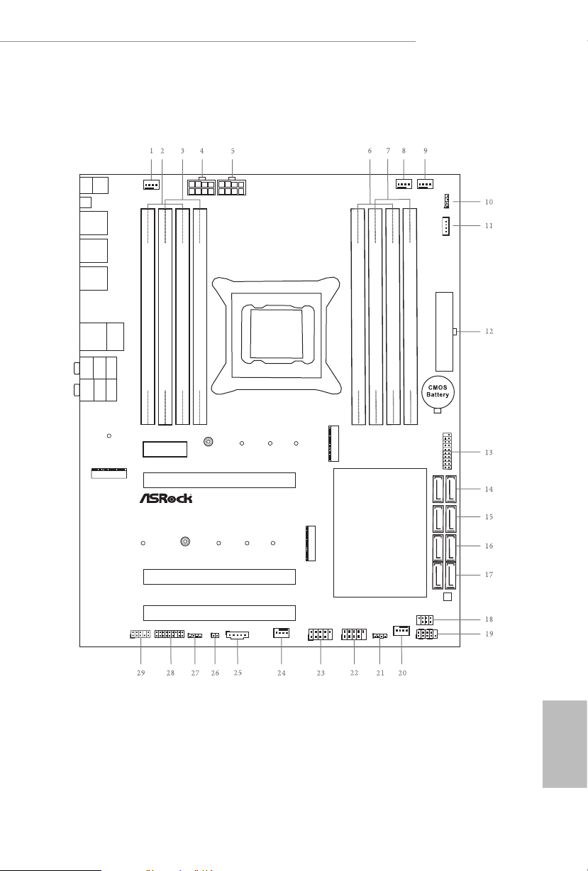
1.3 Motherboard Layout
English
7

No. Description
1 Chassis Fan Connector (CHA_FAN2)
2 2 x 288-pin DDR4 DIMM Slots (DDR4_A1, DDR4_B1)
3 2 x 288-pin DDR4 DIMM Slots (DDR4_A2, DDR4_B2)
4 ATX 12V Power Connector (ATX12V1)
5 ATX 12V Power Connector (ATX12V2)
6 2 x 288-pin DDR4 DIMM Slots (DDR4_C2, DDR4_D2)
7 2 x 288-pin DDR4 DIMM Slots (DDR4_C1, DDR4_D1)
8 CPU Fan Connector (CPU_FAN1)
9 CPU Fan / Waterpump Fan Connector (CPU_OPT/W_PUMP1)
10 RGB LED Header (RGB_LED2)
11 Virtual RAID On CPU Header (VROC1)
12 ATX Power Connector (ATXPWR1)
13 USB 3.1 Gen1 Header (USB3_5_6)
14 SATA3 Connectors (SATA3_0_1)
15 SATA3 Connectors (SATA3_2_3)
16 SATA3 Connectors (SATA3_4_5)
17 SATA3 Connectors (SATA3_6_7)
18 Power LED and Speaker Header (SPK_PLED1)
19 System Panel Header (PANEL1)
20 Chassis Fan Connector (CHA_FAN1)
21 Performance Mode / Easy OC Header (PM_EO)
22 USB 2.0 Header (USB_5_6)
23 USB 2.0 Header (USB_3_4)
24 Chassis Fan / Waterpump Fan Connector (CHA_FAN3/W_PUMP2)
25 underbolt AIC Header (TB1)
26 Clear CMOS Jumper (CLRMOS1)
27 RGB LED Header (RGB_LED1)
28 TPM Header (TPMS1)
29 Front Panel Audio Header (HD_AUDIO1)
English
8
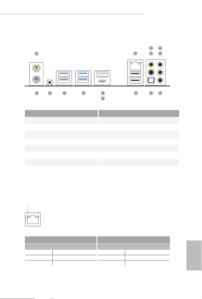
1.4 I/O Panel
1
2
X299 Extreme4
5
436
15
13
14
12
10
11
789
No. Description No. Description
1 PS/2 Mouse Port 9 USB 2.0 Ports (USB_1_2)
2 LAN RJ-45 Port* 10 USB 3.1 Gen2 Type-A Port (USB31_TA_1)
3 Central / Bass (Orange) 11 USB 3.1 Gen2 Type-C Port (USB31_TC_1)
4 Rear Speaker (Black) 12 USB 3.1 Gen1 Ports (USB3_3_4)
5 Line In (Light Blue) 13 USB 3.1 Gen1 Ports (USB3_1_2)
6 Front Speaker (Lime)** 14 Clear CMOS Button
7 Microphone (Pink) 15 PS/2 Keyboard Port
8 Optica l SPDIF Out Port
* ere are two LEDs on each LAN port. Please refer to the table below for the LAN port LED indications .
ACT/LINK L ED
SPEED LE D
LAN Por t
Activity / Link LED Speed LED
Status Description Status Description
O No Link O 10Mbps connection
Blinking Data Activity Orange 100Mbps connection
On Link Green 1Gbps connection
English
9
** If you use a 2- channel speaker, plea se connect the speake r’s plug into “Front Speaker Jack”. See the table below
for connection d etails in accordance w ith the type of speaker you use.
Audio Output
Channels
Front Speaker
(No. 6)
Rear Speaker
(No. 4)
Central / Bass
(No. 3)
2 V -- -- --
4 V V -- --
6 V V V --
8 V V V V
To enable Multi-Streaming, you need to connect a front panel audio cable to the
front panel audio header. Aer restarting your computer, you will nd the “Mixer”
tool on your system. Plea se select “Mixe r ToolBox” , click “Enabl e playba ck
multi-streaming”, and click “ok”. Choose “2CH”, “4CH”, “6CH”, or “8CH” and then
you are all owed to select “Realtek HDA Primary out put” to u se the Rear Speak er,
Central/Bas s, and Front Speaker, or select “Realtek HDA Audio 2nd output” to u se
the front panel au dio.
Line In
(No. 5)
English
10

X299 Extreme4
Chapter 2 Installation
is is an ATX form factor motherboard. Before you install the motherboard, study
the conguration of your chassis to ensure that the motherboard ts into it.
Pre-installation Precautions
Take note of the following precautions before you install motherboard components
or change any motherboard settings.
Make sure to unplug the power cord before installing or removing the motherboard
•
components. Failure to do so may cause physical injuries and damages to motherboard
components.
In order to avoid damage from static electricity to the motherboard’s components,
•
NEVER place your motherboard directly on a carpet. Also remember to use a grounded
wrist strap or touch a safety grounded object before you handle the components.
Hold components by the edges and do not touch the ICs.
•
Whenever you uninstall any components, place them on a grounded anti-static pad or
•
in the bag that comes with the components.
When placing screws to secure the motherboard to the chassis, please do not over-
•
tighten the screws! Doing so may damage the motherboard.
11
English
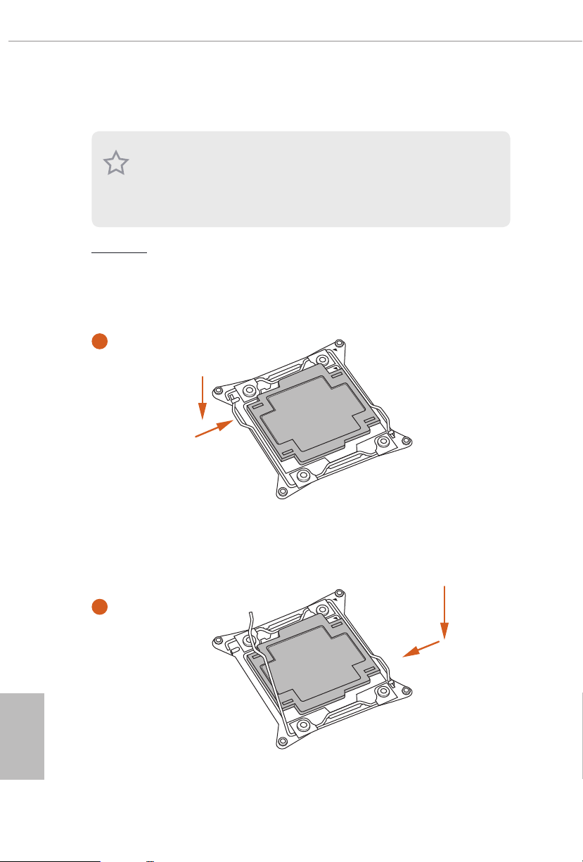
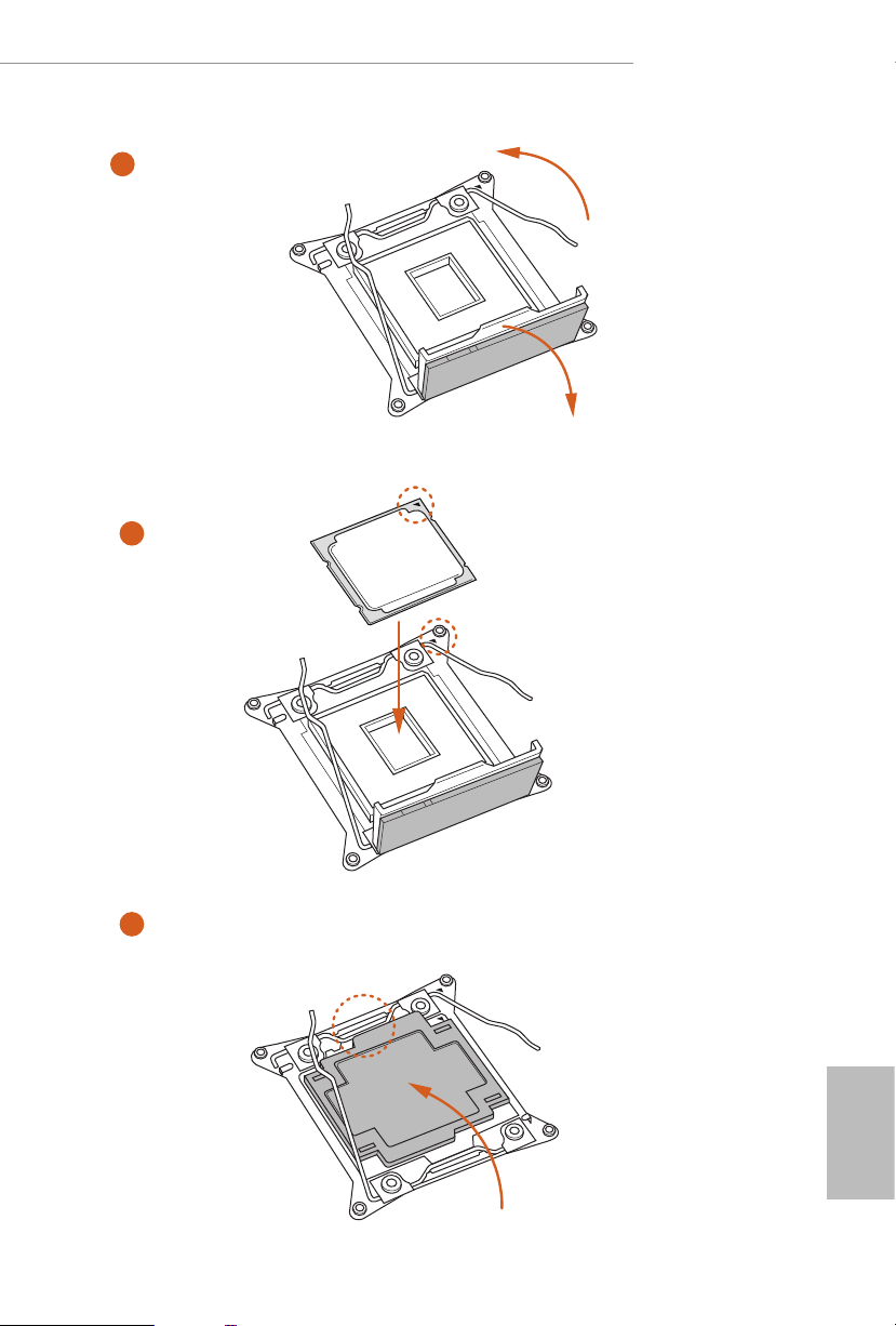
2.1 Installing the CPU
1. Before you insert the 2066 -Pin CPU into the socket, please check if the P nP cap
is on the socket, if the CPU sur face is unclean, or if th ere are any b ent pins in the
socket. Do not force to insert the CPU into the socket if above situ ation is found.
Other wise, the CPU wil l be seriously d amaged.
2. Unplug all power cables be fore installing the CPU.
CAUTION:
Please note that X299 platform is only compatible with the LGA 2066 socket, which is
incompatible with the LGA 2011-3 socket (for X99 platform).
1
A
B
English
12
A
2
B
X299 Extreme4
3
4
A
B
5
English
13
6
A
B
7
A
B
English
14
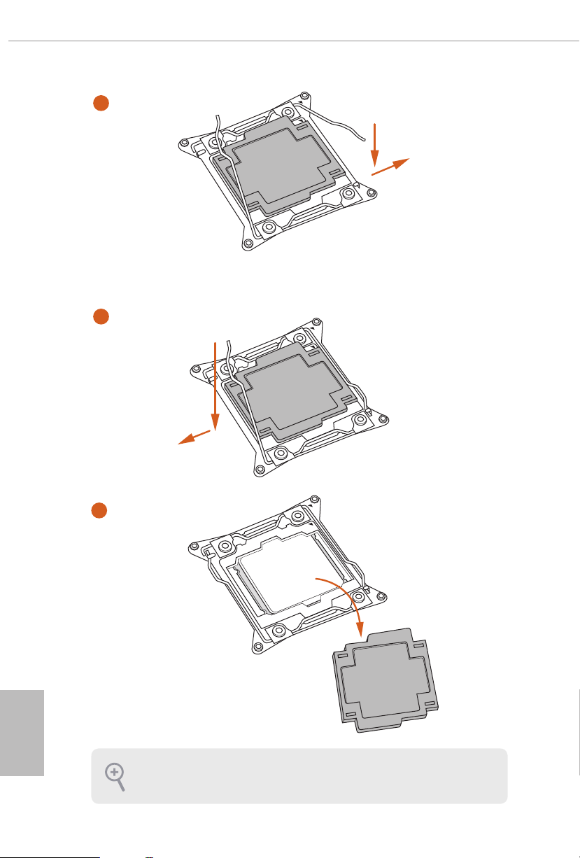
8
Please save and replace the cover if the processor i s removed. e cover must be
placed if you wish to return the motherboard for aer service.
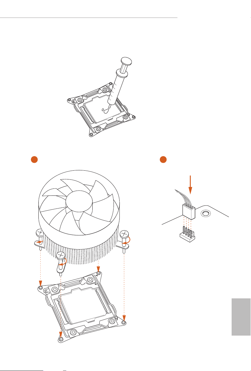
2.2 Installing the CPU Fan and Heatsink
1 2
X299 Extreme4
FAN
CPU_
English
15
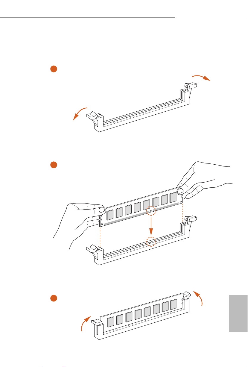
2.3 Installation of Memory Modules (DIMM)
is motherboard provides eight 288-pin DDR4 (Double Data Rate 4) DIMM slots, and
supports Quad Channel Memory Technology.
1. For quad channel c onguration, you always ne ed to ins tall identical (the same
brand, speed , size and chip-type) DDR4 DIMM pairs.
2. It is not allowed to install a DDR, DDR2 or DDR3 memory module into a DDR4
slot; otherwise, this motherboard and DIMM may be damaged.
3. e DIMM only ts in one correct orientation. It will cause permanent dam age to
the mothe rboard and the DIMM if you force the DIMM into the slot at incor rect
orientation .
Quad Channel Memory Conguration (For CPU with 44 or 28 PCIe lanes)
Priority 1 2
DDR4_B1
DDR4_B2
DDR4_ A1
DDR4_ A2
DDR4_D1
DDR4_D2
DDR4_C1
DDR4_C2
Populated Populated
Populated
Populated Populated
Populated
Populated Populated
Populated
Populated Populated
Populated
English
16
Dual Channel Memory Conguration (For CPU with 16 PCIe lanes)
Priority 1 2
DDR4_D1
DDR4_D2
DDR4_C1
DDR4_C2
Due to Intel® CPU spec denition, please install the memory modules on DDR4_A1,
•
DDR4_B1, DDR4_C1 and DDR4_D1 for rst priority. If the four DDR4 DIMM slots
above are fully installed, and you want to use more than four memory modules, please
install the other memory modules from le to right (from DDR4_A2, DDR4_B2,
DDR4_D2 to DDR4_C2.)
If only two memory modules are installed in the DDR4 DIMM slots, then Dual
•
Channel Memory Technology is activated. If three memory modules are installed, then
Triple Channel Memory Technology is activated. If more than four memory modules
are installed in the DDR4 DIMM slots, then Quad Channel Memory Technology is
activated.
Populated Populated
Populated
Populated Populated
Populated
X299 Extreme4
For CPU with 16 PCIe lanes, please install the memory modules on DDR4_C1, C2, D1
•
and D2 only.
1
2
3
English
17

2.4 Expansion Slots (PCI Express Slots)
ere are 4 PCI Express slots on the motherboard.
Before installing an ex pansion card, please make sure that the power supply is
switched o or the power cord is unplugged. Plea se read the documentation of the
expan sion card and mak e necessary hardware settings for the card before you start
the installation.
PCIe slots:
PCIE1 (PCIe 3.0 x1 slot) is used for PCI Express x1 lane width cards.
PCIE2 (PCIe 3.0 x16 slot) is used for PCI Express x16 lane width graphics cards.
PCIE3 (PCIe 3.0 x16 slot) is used for PCI Express x16 lane width graphics cards.
PCIE4 (PCIe 3.0 x16 slot) is used for PCI Express x4 lane width graphics cards.
* If you install CPU with 44 lanes, PCIE2/PCIE3/PCIE4 will run at x16/x16/x4.
* If you install CPU with 28 lanes, PCIE2/PCIE3/PCIE4 will run at x16/x8/x4.
* If you install CPU with 16 lanes, PCIE2/PCIE3/PCIE4 will run at x16/x0/x4 or x8/
x8/x4.
* If PCIE1 slot is occupied, M2_3 slot will be disabled.
PCIe Slot Congurations (For CPU with 44 PCIe lanes)
PCIE2 PCIE3 PCIE4
English
18
Single Graphics Card x16 N/A N/A
Two Graphics Cards in
CrossFireXTM or SLITM
Mode
x16 x16 N/A

PCIe Slot Congurations (For CPU with 28 PCIe lanes)
PCIE2 PCIE3 PCIE4
Single Graphics Card x16 N/A N/A
Two Graphics Cards in
CrossFireXTM or SLITM
Mode
x16 x8 N/A
PCIe Slot Congurations (For CPU with 16 PCIe lanes)
PCIE2 PCIE3 PCIE4
Single Graphics Card x16 N/A N/A
Two Graphics Cards in
CrossFireXTM or SLITM
Mode
x8 x8 N/A
X299 Extreme4
For a better ther mal environment, ple ase connect a ch assi s fan to the motherboard’s
chassis fan connector (CHA_ FAN1, CHA_ FA N2 or CHA_FAN3) when u sing multiple graphics cards.
English
19
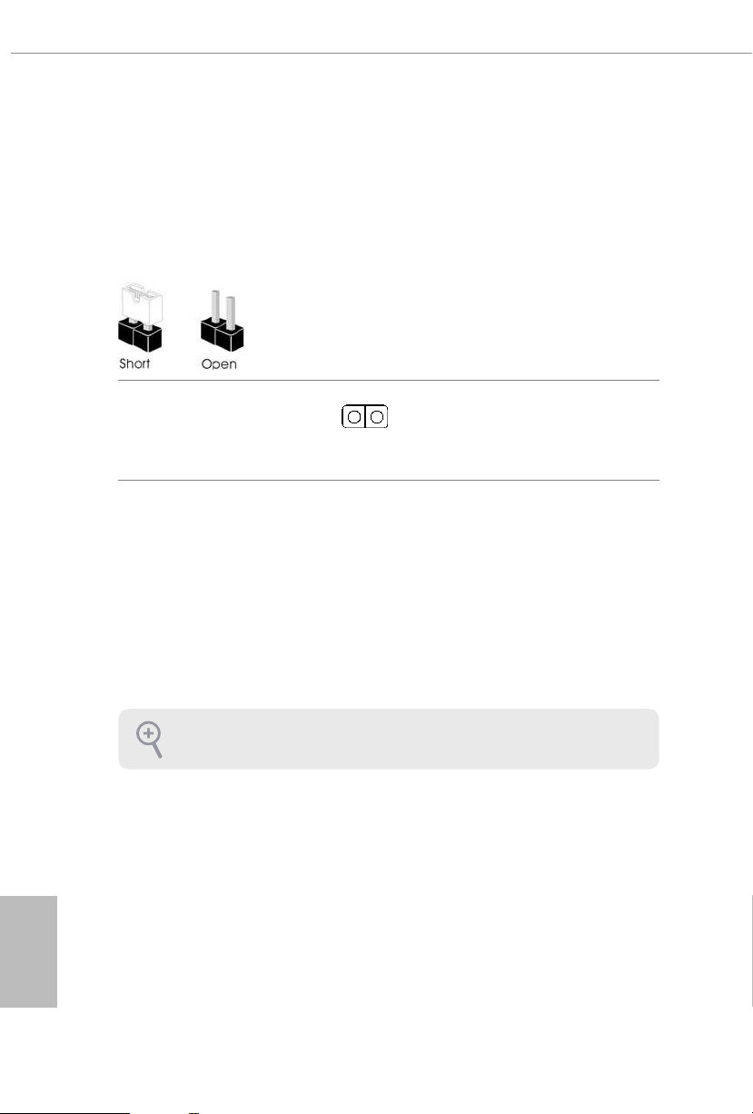
2.5 Jumpers Setup
e illustration shows how jumpers are setup. When the jumper cap is placed on
the pins, the jumper is “Short”. If no jumper cap is placed on the pins, the jumper is
“Open”.
Clear CMOS Jumper
(CLRMOS1)
(see p.7, No. 26)
CLRMOS1 allows you to clear the data in CMOS. To clear and reset the system
parameters to default setup, please turn o the computer and unplug the power
cord from the power supply. Aer waiting for 15 seconds, use a jumper cap to
short the pins on CLR MOS1 for 5 seconds. However, please do not clear the
CMOS right aer you update the BIOS. If you need to clear the CMOS when you
just nish updating the BIOS, you must boot up the system rst, and then shut it
down before you do the clear-CMOS action. Please be noted that the password,
date, time, and user default prole will be cleared only if the CMOS battery is
removed. Please remember toremove the jumper cap aer clearing the CMOS.
2-pin Jumper
English
20
e Clear CMOS Button has the same function as the Cl ear CMOS jumper.
2.6 Onboard Headers and Connectors
Onboard headers and connectors are NOT jumpers. Do NOT place jumper caps over
these header s and connectors. Placing jumper caps over the headers and connectors
will cause permanent damage to the motherboard.
X299 Extreme4
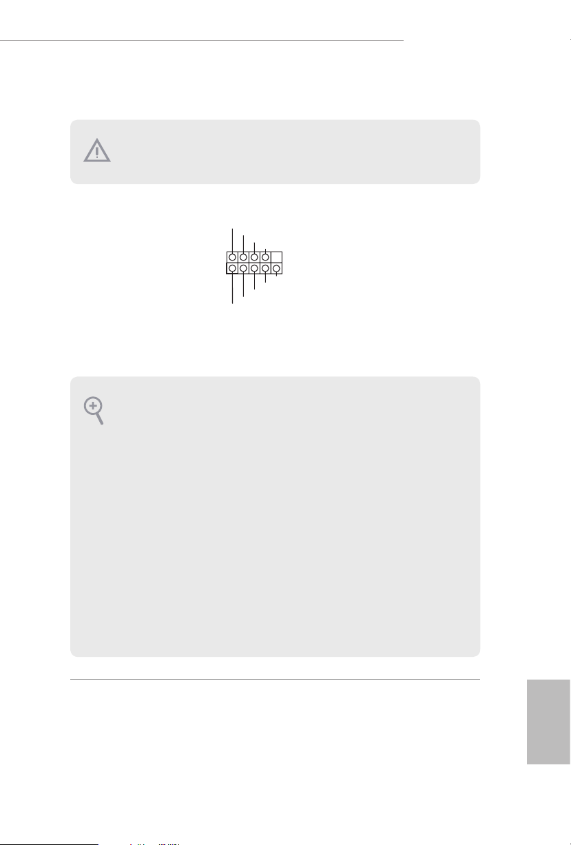
System Panel Header
(9-pin PANEL1)
(see p.7, No. 19)
PWRBTN (Power Switch):
Connec t to the power switch on the chassi s front panel. You may congure the way to
turn o your system using the power switch.
RESET (Reset Switch):
Connec t to the reset switch on the chassi s front panel. P ress the reset sw itch to restart
the computer if the compute r freezes and fails to perform a normal restart.
PLED (Syste m Power LED):
Connec t to the power status indicator on the chassis front panel. e LED i s on when
the system is ope rating. e LED keeps blinking when the system i s in S1/S3 sleep
state. e LED is o when the system is in S4 sleep state or powered o (S5).
HDLED (Ha rd Drive Activity LED):
Connec t to the hard drive ac tivity LED on the chassis front panel. e LED is on
when the hard drive i s reading or writing data.
e front panel de sign may dier by chassis. A front pane l module mainly consists
of power switch , reset switch, power LED, hard dr ive activity LED, speak er and etc.
When connecting your chassis front panel module to this head er, make sure the wire
assig nments and the pin assig nments are matched correctly.
1
PLE D+
PLE D-
HDL ED-
HDL ED+
PWR BTN #
GND
RES ET#
GND
GND
Connect the power
switch, reset switch and
system status indicator on
the chassis to this header
according to the pin
assignments below. Note
the positive and negative
pins before connecting
the cables.
21
English
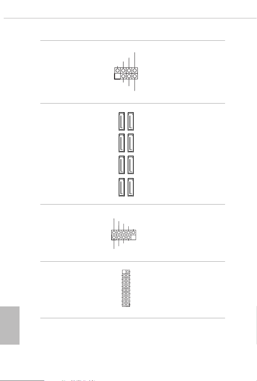
Power LED and Speaker
PLE D-
Header
(7-pin SPK_PLED1)
(see p.7, No. 18)
DUM MY
+5V
1
PLE D+
SPE AK ER
DUM MY
PLE D+
Please connect the
chassis power LED and
the chassis speaker to this
header.
English
Serial ATA3 Connectors
(SATA3_0_1:
see p.7, No. 14)
(SATA3_2_3:
see p.7, No. 15)
(SATA3_4_5:
see p.7, No. 16)
(SATA3_6_7:
see p.7, No. 17)
USB 2.0 Headers
(9-pin USB_3_4)
(see p.7, No. 23)
(9-pin USB_5_6)
(see p.7, No. 22)
USB 3.1 Gen1 Header
(19-pin USB3_5_6)
(see p.7, No. 13)
SATA3_0
SATA3_2
SATA3_4
SATA3_6
USB _PW R
1
USB _PW R
IntA _PA_S SRX-
IntA _PA_S SRX+
IntA _PA_S STX-
IntA _PA_S STX+
IntA _PA_D -
IntA _PA_D +
Vbus
GND
GND
ese eight SATA3
connectors support SATA
data cables for internal
SATA3_1
storage devices with up to
6.0 Gb/s data transfer rate.
* If M2_1 is occupied by
SATA3_3
a SATA-type M.2 device,
SATA3_0 will be disabled.
SATA3_5
* If M2_2 is occupied by
a SATA-type M.2 device,
SATA3_1 will be disabled.
SATA3_7
ere are two headers
P-
P+
GND
DUM MY
on this motherboard.
Each USB 2.0 header can
support two ports.
GND
P+
P-
VbusVbus
IntA _PB_ SSRX -
IntA _PB_ SSRX +
GND
IntA _PB_ SSTX -
IntA _PB_ SSTX +
GND
IntA _PB_ D-
IntA _PB_ D+
Dumm y
1
ere is one header on
this motherboard. is
USB 3.1 Gen1 header can
support two ports.
22
X299 Extreme4
GND
FAN_V OLTAGE _CO NTRO L
FAN_S PEE D
FAN_S PEE D_CO NTR OL
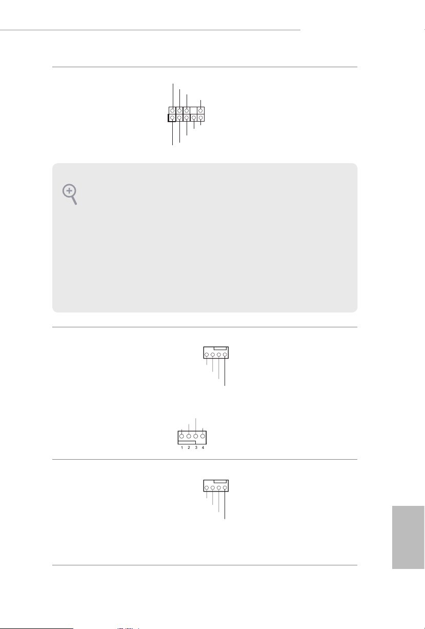
Front Panel Audio Header
(9-pin HD_AUDIO1)
(see p.7, No. 29)
1. High Denition Audio supports Jack Sensing, but the panel wire on the chassis
must support HDA to function correctly. Please follow the instructions in our
manual and chassis manual to install your system.
2. If you use an AC’97 audio panel, please install it to the front panel audio heade r by
the steps below:
A. Connect Mic_IN (MIC) to MIC2_ L.
B. Conne ct Audio_R (RIN) to OUT2_R and Audio_ L (LIN) to OUT2_ L.
C. Connect Ground (GND) to Ground (GND).
D. MIC_ RET and OUT_RET are for the HD audio panel only. You don’t need to
connec t them for the AC’97 audio panel.
E. To activate the front mic, go to the “FrontMic” Tab in the Realtek Control panel
and adju st “Recording Volume”.
Chassis Fan Connectors
(4-pin CHA_FAN1)
(see p.7, No. 20)
GND
PRE SEN CE#
MIC _RE T
1
J_S ENS E
OUT 2_R
MIC 2_R
MIC 2_L
FAN _SP EED _CO NTR OL
CHA _FA N_S PEE D
FAN _VO LTA GE
OUT _RE T
OUT 2_L
4 3 2 1
is header is for
connecting audio devices
to the front audio panel.
Please connect fan cables
to the fan connectors and
match the black wire to
the ground pin.
GND
(4-pin CHA_FAN2)
(see p.7, No. 1)
Chassis Optional/Water
Pump Fan Connector
(4-pin CHA_FAN3/W_
PUMP2)
(see p.7, No. 24)
FAN _SP EED _CO NTR OL
CHA _FA N_S PEE D
FAN _VO LTA GE
4 3 2 1
is motherboard
provides a 4-Pin water
cooling
chassis
connector. If you plan to
GND
connect a 3-Pin
water cooler fan, please
connect it to Pin 1-3.
fan
chassis
English
23
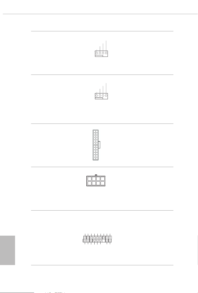
CPU Fan Connector
FAN_S PEED_ CONTR OL
5
1
8
(4-pin CPU_FAN1)
(see p.7, No. 8)
FAN_S PEED_ CONTR OL
CPU_ FAN_SP EED
FAN_ VOLTA GE
GND
1 2 3 4
is motherboard
provides a 4-Pin CPU fan
(Quiet Fan) connector.
If you plan to connect a
3-Pin CPU fan, please
connect it to Pin 1-3.
English
CPU Optional/Water
Pump Fan Connector
(4-pin CPU_OPT/W_
PUMP)
(see p.7, No. 9)
ATX Power Connector
(24-pin ATXPWR1)
(see p.7, No. 12)
ATX 12V Power
Connectors
(8-pin ATX12V1)
(see p.7, No. 4)
(8-pin ATX12V2)
(see p.7, No. 5)
TPM Header
(17-pin TPMS1)
(see p.7, No. 28)
CPU_ FAN_SP EED
FAN_ VOLTA GE
12
1
GND
1
PCIC LK
is motherboard
GND
1 2 3 4
provides a 4-Pin water
cooling CPU fan
connector. If you plan
to connect a 3-Pin CPU
water cooler fan, please
connect it to Pin 1-3.
24
is motherboard
provides a 24-pin ATX
power connector. To use a
20-pin ATX power supply,
please plug it along Pin 1
13
and Pin 13.
is motherboard
provides two 8-pin ATX
12V power connectors. To
use a 4-pin ATX power
supply, please plug it along
Pin 1 and Pin 5.
is connector supports Trusted
Platform Module (TPM) system,
SMB_ CLK _MAI N
SMB_ DAT A_MA IN
LAD2
GND
LAD1
S_PW RDW N#
which can securely store keys,
SERI RQ#
GND
digital certicates, passwords,
and data. A TPM system also
+3V
LAD3
LAD0
FRAM E
PCIR ST#
helps enhance network security,
GND
+3VS B
protects digital identities, and
ensures platform integrity.
24
 Loading...