

Page 1
Copyright Notice:Copyright Notice:
Copyright Notice:
Copyright Notice:Copyright Notice:
No part of this installation guide may be reproduced, transcribed, transmitted, or translated in any language, in any form or by any means, except duplication of documentation by the purchaser for backup purpose, without written consent of ASRock Inc.
Products and corporate names appearing in this guide may or may not be registered
trademarks or copyrights of their respective companies, and are used only for identification or explanation and to the owners’ benefit, without intent to infringe.
Disclaimer:Disclaimer:
Disclaimer:
Disclaimer:Disclaimer:
Specifications and information contained in this guide are furnished for informational
use only and subject to change without notice, and should not be constructed as a
commitment by ASRock. ASRock assumes no responsibility for any errors or omissions
that may appear in this guide.
With respect to the contents of this guide, ASRock does not provide warranty of any kind,
either expressed or implied, including but not limited to the implied warranties or
conditions of merchantability or fitness for a particular purpose. In no event shall
ASRock, its directors, officers, employees, or agents be liable for any indirect, special,
incidental, or consequential damages (including damages for loss of profits, loss of
business, loss of data, interruption of business and the like), even if ASRock has been
advised of the possibility of such damages arising from any defect or error in the guide
or product.
This device complies with Part 15 of the FCC Rules. Operation is subject to the
following two conditions:
(1) this device may not cause harmful interference, and
(2) this device must accept any interference received, including interference that
may cause undesired operation.
CALIFORNIA, USA ONLY
The Lithium battery adopted on this motherboard contains Perchlorate, a toxic
substance controlled in Perchlorate Best Management Practices (BMP) regulations
passed by the California Legislature. When you discard the Lithium battery in
California, USA, please follow the related regulations in advance.
“Perchlorate Material-special handling may apply, see
www.dtsc.ca.gov/hazardouswaste/perchlorate”
ASRock Website: http://www.asrock.com
Published October 2007
Copyright©2007 ASRock INC. All rights reserved.
ASRock Wolfdale1333-D667 Motherboard
EnglishEnglish
EnglishEnglish
English
11
1
11
Page 2
Motherboard LMotherboard L
Motherboard L
Motherboard LMotherboard L
ayoutayout
ayout
ayoutayout
English
EnglishEnglish
EnglishEnglish
22
2
22
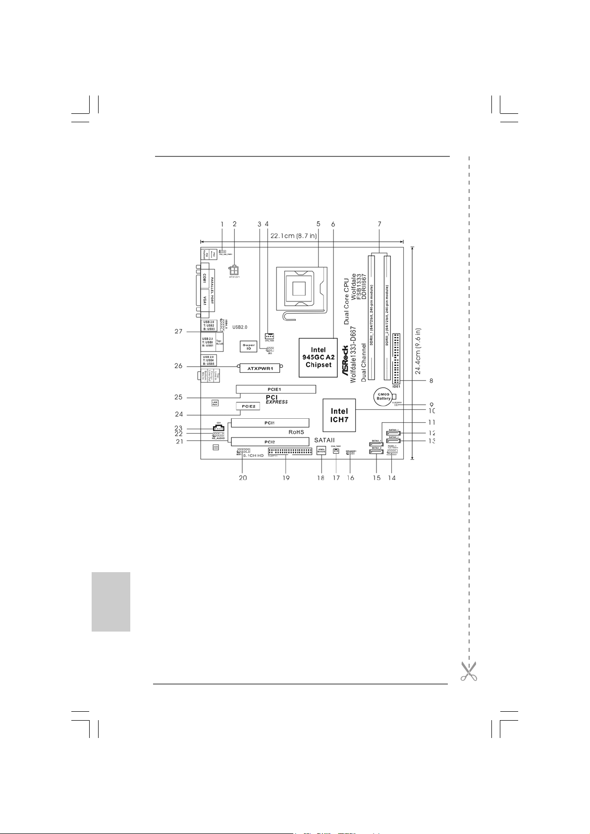
1 PS2_USB_PWR1 Jumper 14 System Panel Header (PANEL1)
2 ATX 12V Connector (ATX12V1) 15 Secondary SATAII Connector
3 DeskExpress Hot Plug Detection Header (SATAII_2; Red)
(IR1) 16 Chassis Speaker Header (SPEAKER 1)
4 CPU Fan Connector (CPU_FAN1) 17 Chassis Fan Connector (CHA_FAN1)
5 775-Pin CPU Socket 18 BIOS SPI Chip
6 North Bridge Controller 19 Floppy Connector (FLOPPY1)
7 2 x 240-pin DDRII DIMM Slots 20 WiFi Header (WIFI)
(Dual Channel: DDRII_1, DDRII_2; Yellow) 21 PCI Slots (PCI1- 2)
8 IDE1 Connector (IDE1, Blue) 22 Front Panel Audio Header (HD_AUDIO1)
9 Clear CMOS Jumper (CLRCMOS1) 23 AInternal Audio Connector: CD1 (Black)
10 South Bridge Controller 24 PCI Express x1 Slot (PCIE2)
11 Primary SATAII Connector (SATAII_1; Red) 25 PCI Express x16 Slot (PCIE1)
12 Third SATAII Connector (SATAII_3; Orange) 26 ATX Power Connector (ATXPWR1)
13 Fourth SATAII Connector (SATAII_4; Orange) 27 Shared USB 2.0 Header (USB4_5, Blue)
ASRock Wolfdale1333-D667 Motherboard
Page 3
TMTM
TM
ASRock 6CH I/O PlusASRock 6CH I/O Plus
ASRock 6CH I/O Plus
ASRock 6CH I/O PlusASRock 6CH I/O Plus
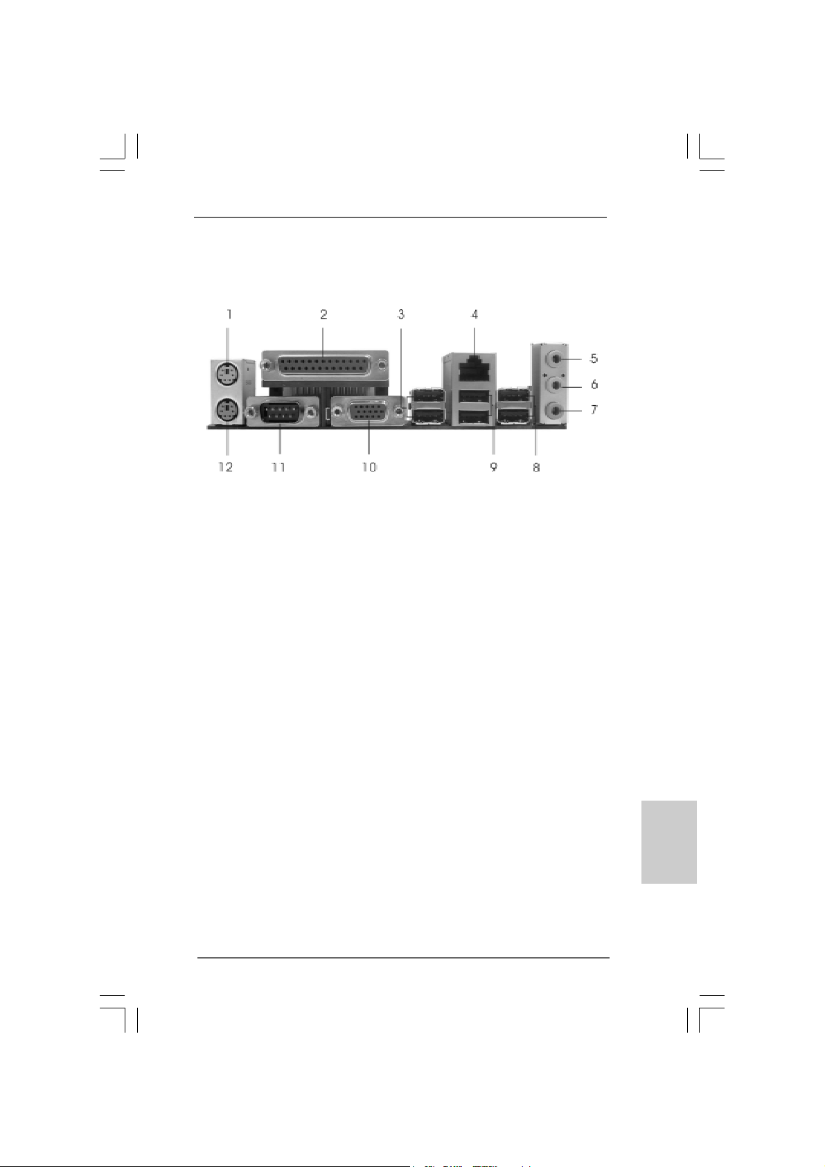
1 PS/2 Mouse Port (Green) 7 Microphone (Pink)
2 Parallel Port 8 Shared USB 2.0 Ports (USB45)
3 USB 2.0 Ports (USB23) 9 USB 2.0 Ports (USB01)
4 RJ-45 Port 10 VGA Port
5 Line In (Light Blue) 11 COM Port
6 Line Out (Lime) 12 PS/2 Keyboard Port (Purple)
TMTM
ASRock Wolfdale1333-D667 Motherboard
EnglishEnglish
EnglishEnglish
English
33
3
33
Page 4
1. Introduction1. Introduction
1. Introduction
1. Introduction1. Introduction
Thank you for purcha sing ASRock Wolfdale1333-D667 motherboard, a reliable mother-
board produced under ASRock’s consistently stringent quality control. It delivers excellent performance with robust design conf orming to ASRock’s commitment to quality a nd
endurance.
This Quick Installation Guide contains introduction of the motherboard and step-bystep installation guide. More detailed information of the motherboard can be found in
the user manual presented in the Support CD.
Because the motherboard specifications and the BIOS software might
be updated, the content of this manual will be subject to change without
notice. In case any modifications of this manual occur, the updated
version will be available on ASRock website without further notice. You
may find the latest VGA cards and CPU support lists on ASRock website
as well. ASRock website http://www.asrock.com
If you require technical support related to this motherboard, please visit
our website for specific information about the model you are using.
www.asrock.com/support/index.asp
1.1 P1.1 P
ackack
1.1 P
1.1 P1.1 P
ASRock Wolfdale1333-D667 Motherboard
(Micro ATX Form Factor: 9.6-in x 8.7-in, 24.4 cm x 22.1 cm)
ASRock Wolfdale1333-D667 Quick Installation Guide
ASRock Wolfdale1333-D667 Support CD
One 80-conductor Ultra A TA 66/100 IDE Ribbon Cable
One Ribbon Cable for a 3.5-in Floppy Drive
One Serial AT A (SAT A) Data Cable (Optional)
One Serial AT A (SA TA) HDD Power Cable (Optional)
One “ASRock 6CH I/O Plus” I/O Shield
age Contentsage Contents
ack
age Contents
ackack
age Contentsage Contents
English
EnglishEnglish
EnglishEnglish
44
4
44
ASRock Wolfdale1333-D667 Motherboard
Page 5
1.21.2
SpecificationsSpecifications
1.2
Specifications
1.21.2
SpecificationsSpecifications
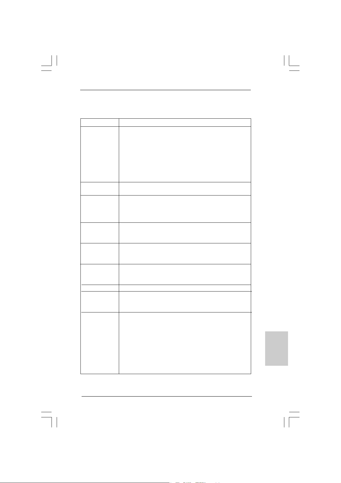
Platform - Micro ATX Form Factor: 9.6-in x 8.7-in, 24.4 cm x 22.1 cm
CPU - LGA 775 f or Intel® Dual Core CoreTM 2 Extreme / CoreTM 2 Duo
/ Pentium® Dual Core / Celeron®, supporting Dual Core W olfdale
processors
- Compatible with all FSB1333/1066/800/533MHz CPUs
except Quad Core (see CAUTION 1)
- Supports Hyper-Threading Technology (see CAUTION 2)
- Supports Untied Overclocking Technology (see CAUTION 3)
- Supports EM64T CPU
Chipset - Northbridge: Intel® 945GC A2
- Southbridge: Intel® ICH7
Memory - Dual Channel DDRII Memory Technology (see CAUTION 4)
- 2 x DDRII DIMM slots
- Support DDRII667/533 (see CAUTION 5)
- Max. capacity: 4GB (see CAUTION 6)
Hybrid Booster - CPU Frequency Stepless Control (see CAUTION 7)
- ASRock U-COP (see CAUTION 8)
- Boot Failure Guard (B.F.G.)
Expansion Slot - 1 x PCI Express x16 slot
- 1 x PCI Express x1 slot
- 2 x PCI slots
Graphics - Intel® Graphics Media Accelerator 950
- Pixel Shader 2.0, Dire ctX 9.0
- Max. shared memory 224MB (see CAUTION 9)
Audio - 5.1 CH High Definition Audio (Re altek ALC660VD Audio Code c)
LAN - Realtek PCIE x1 LAN 8101E
- Speed: 10/100 Ethernet
- Supports Wa ke-On-LAN
Rear Panel I/O ASRock 6CH I/O Plus
- 1 x PS/2 Mouse Port
- 1 x PS/2 Keyboard Port
- 1 x Serial Port: COM1
- 1 x VGA Port
- 1 x Parallel Port (ECP/EPP Support)
- 6 x Ready-to-Use USB 2.0 Ports
- 1 x RJ-45 LAN Port
- HD Audio Jack: Line in / Front Spea ker / Microphone
EnglishEnglish
EnglishEnglish
English
ASRock Wolfdale1333-D667 Motherboard
55
5
55
Page 6
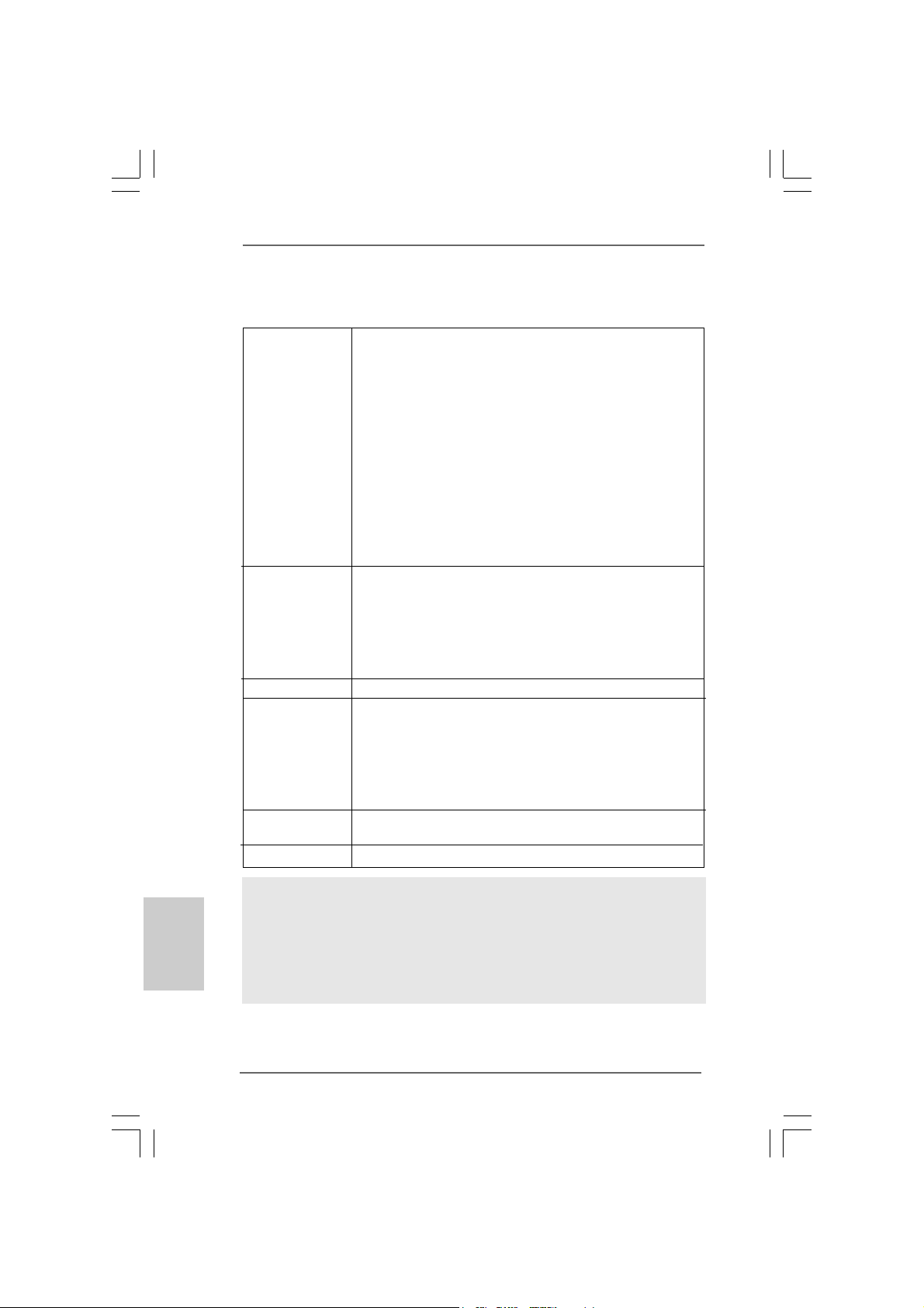
Connector - 4 x SATAII 3.0 Gb/s connectors (No Support f or RAID and “Hot
Plug” functions) (see CAUTION 10)
- 1 x ATA100 IDE conne ctor (supports 2 x IDE devices)
- 1 x Floppy connector
- 1 x DeskExpre ss Hot Plug Detection header
- CPU/Chassis FAN connector
- 24 pin A TX power conne ctor
- 4 pin 12V power connector
- CD in header
- Front panel audio connector
- 1 x USB 2.0 header (supports 2 USB 2.0 ports; shared with
USB45 ports on the I/O panel) (see CAUTION 1 1)
- 1 x WiFi header (see CAUTION 12)
BIOS Feature - 4Mb AMI BIOS
- AMI Legal BIOS
- Supports “Plug and Play”
- ACPI 1.1 Compliance Wa ke Up Events
- Supports jumperfree
- AMBIOS 2.3.1 Support
Support CD - Drivers, Utilities, AntiV irus Software (T ri al Version)
Hardware - CPU T e mperature Sensing
Monitor - Chassis Temperature Sensing
- CPU Fan Ta chometer
- Chassis Fa n Ta chometer
- CPU Quiet Fan
- Voltage Monitoring: +12V, +5V, +3.3V, Vcore
OS - Microsoft® Windows® 2000 / XP / XP 64-bit / Vista
TM
/
VistaTM 64-bit compliant
Certifications - FCC, CE, WHQL
English
EnglishEnglish
EnglishEnglish
66
6
66
WARNING
Please realize that there is a certain risk involved with overclocking, including adjusting
the setting in the BIOS, applying Untied Overclocking Technology, or using the thirdparty overclocking tools. Overclocking may affect your system stability, or even
cause damage to the components and devices of your system. It should be done at
your own risk and expense. We are not responsible for possible damage caused by
overclocking.
ASRock Wolfdale1333-D667 Motherboard
Page 7
CAUTION!
1. FSB1333-CPU will operate in overclocking mode. Under this situation,
PCIE frequency will also be overclocked to 115MHz.
2. About the setting of “Hyper Threading Technology”, please check page
28 of “User Manual” in the support CD.
3. This motherboard supports Untied Overclocking Technology. Please read
“Untied Overclocking Technology” on page 20 for details.
4. This motherboard supports Dual Channel Memory Technology. Before
you implement Dual Channel Memory Technology, make sure to read
the installation guide of memory modules on page 12 for proper
installation.
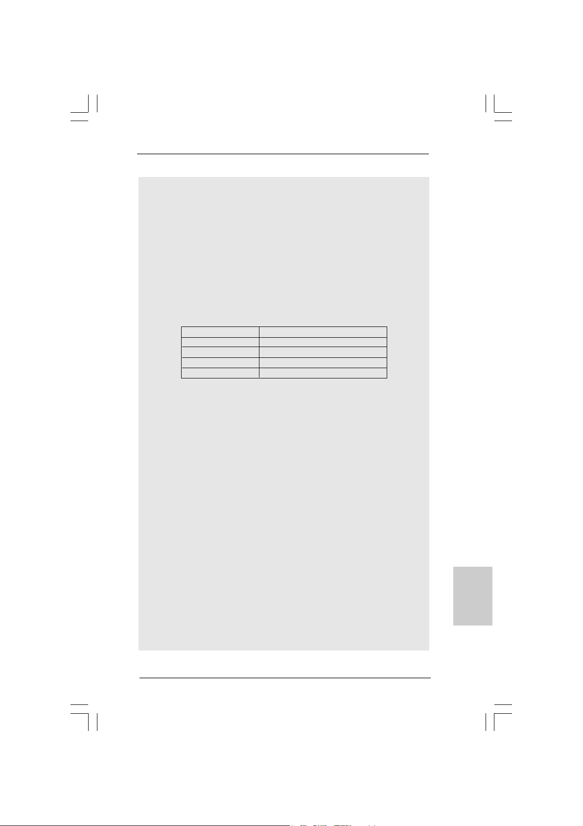
5. Please check the table below for the CPU FSB frequency and its corresponding memory support frequency.
CPU FSB Frequency Memory Support Frequency
1333 DDRII533*, DDRII667
1066 DDRII533, DDRII667
800 DDRII400, DDRII533, DDRII667
533 DDRII400, DDRII533
* When you use a FSB1333-CPU on this motherboard, it will run at
DDRII500 if you adopt a DDRII533 memory module.
6. Due to the chipset limitation, the actual memory size may be less than
4GB for the reservation for system usage under Windows® XP, Windows® XP 64-bit, Windows® VistaTM and Windows® VistaTM 64-bit.
7. Although this motherboard offers stepless control, it is not recommended to perform over-clocking. Frequencies other than the recommended CPU bus frequencies may cause the instability of the system
or damage the CPU.
8. While CPU overheat is detected, the system will automatically shutdown.
Before you resume the system, please check if the CPU fan on the
motherboard functions properly and unplug the power cord, then plug it
back again. To improve heat dissipation, remember to spray thermal
grease between the CPU and the heatsink when you install the PC
system.
9. The maximum shared memory size is defined by the chipset vendor
and is subject to change. Please check Intel® website for the latest
information.
10. Before installing SA TAII hard disk to SATAII connector, ple ase read the “SATAII
Hard Disk Setup Guide” on page 19 to adjust your SATAII hard disk drive to
SATAII mode. You can also connect SATA hard disk to SATAII connector
directly.
11. Power Management for USB 2.0 works fine under Microsoft® Windows
VistaTM 64-bit / VistaTM / XP 64-bit / XP SP1 or SP2 / 2000 SP4.
®
EnglishEnglish
EnglishEnglish
English
ASRock Wolfdale1333-D667 Motherboard
77
7
77
Page 8
12. WiFi header supports WiFi+AP function with ASRock WiFi-802.11g /
WiFi-802.11n module, an easy-to-use wireless local area network
(WLAN) adapter. It allows you to create a wireless environment and
enjoy the convenience of wireless network connectivity. Please visit our
website for the availability of ASRock WiFi-802.11g / WiFi-802.11n
module.
ASRock website http://www.asrock.com
English
EnglishEnglish
EnglishEnglish
88
8
88
ASRock Wolfdale1333-D667 Motherboard
Page 9
2.2.
InstallationInstallation
2.
Installation
2.2.
InstallationInstallation
Pre-installation PrecautionsPre-installation Precautions
Pre-installation Precautions
Pre-installation PrecautionsPre-installation Precautions
Take note of the following precautions before you install motherboard components or change any motherboard settings.
1. Unplug the power cord from the wall socket before touching any
component. Failure to do so may cause severe damage to the
motherboard, peripherals, and/or components.
2. To avoid damaging the motherboard components due to static
electricity, NEVER place your motherboard directly on the carpet
or the like. Also remember to use a grounded wrist strap or touch
a safety grounded object before you handle components.
3. Hold components by the edges and do not touch the ICs.
4. Whenever you uninstall any component, place it on a grounded
antstatic pad or in the bag that comes with the component.
5. When placing screws into the screw holes to secure the
motherboard to the chassis, please do not over-tighten the
screws! Doing so may damage the motherboard.
2.12.1
CPU InstallationCPU Installation
2.1
CPU Installation
2.12.1
CPU InstallationCPU Installation
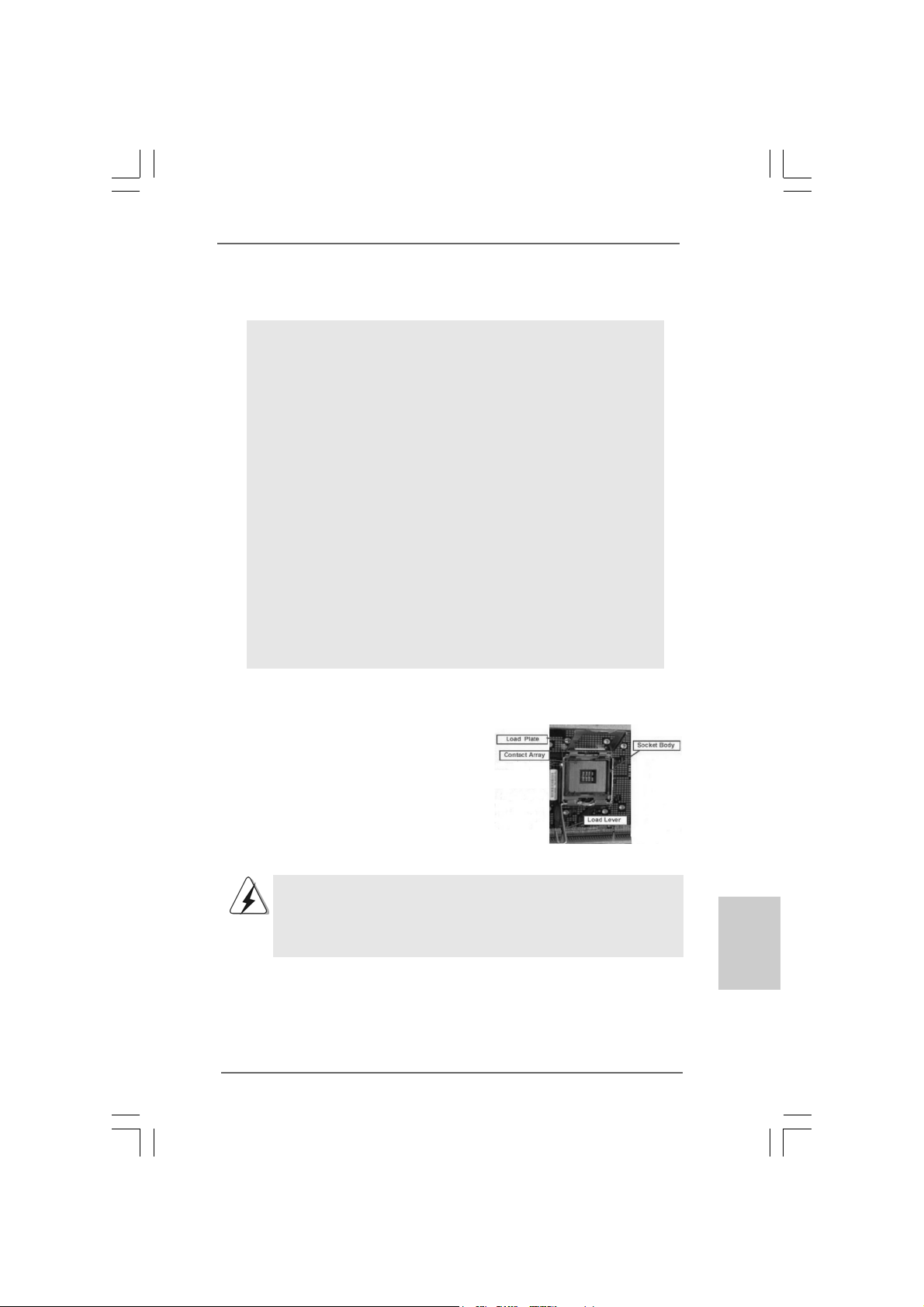
For the installation of Intel 775-LAND CPU,
please follow the steps below.
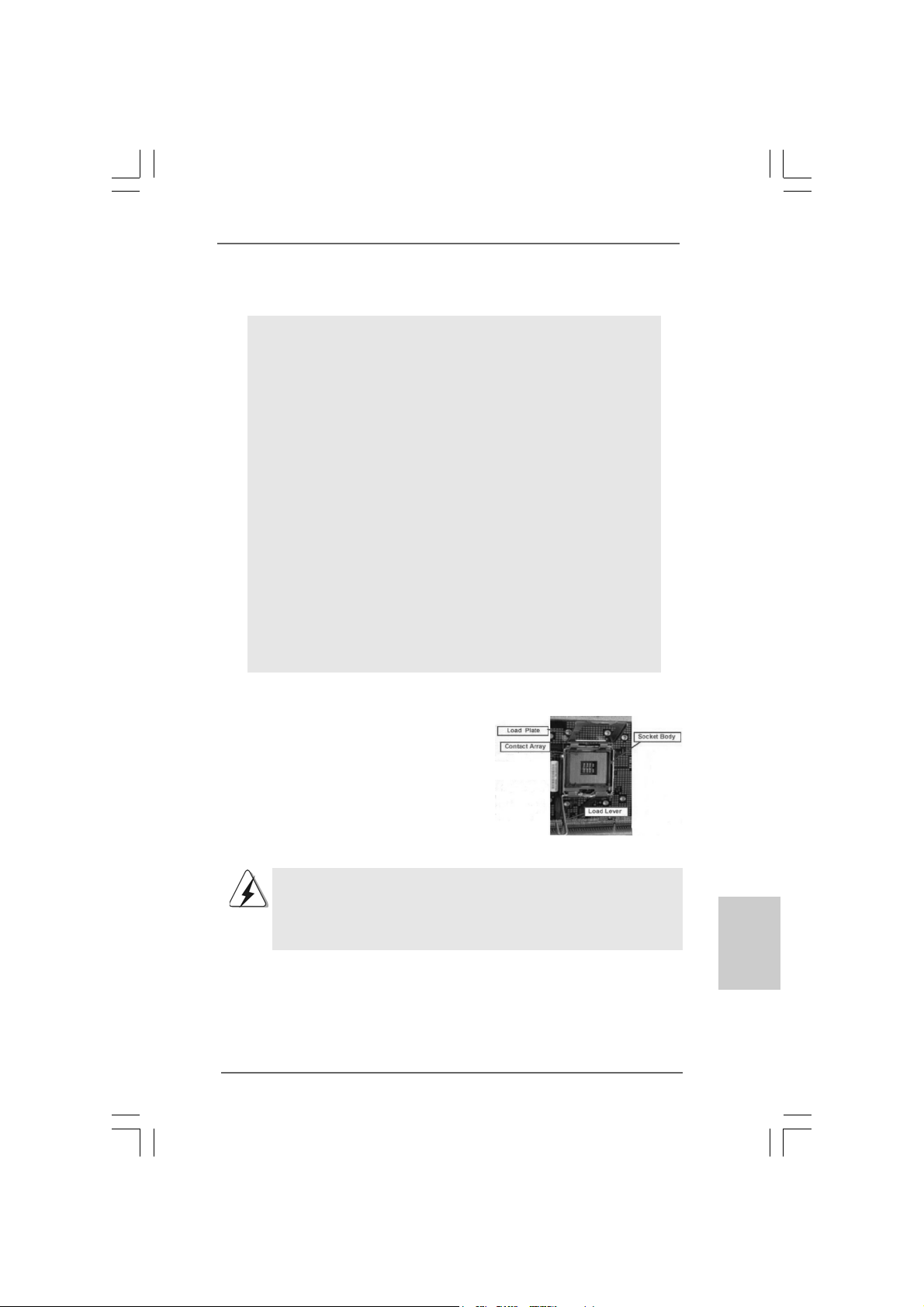
775-Pin Socket Overview
Before you insert the 775-LAND CPU into the socket, please check if
the CPU surface is unclean or if there is any bent pin on the socket.
Do not force to insert the CPU into the socket if above situation is
found. Otherwise, the CPU will be seriously damaged.
ASRock Wolfdale1333-D667 Motherboard
EnglishEnglish
EnglishEnglish
English
99
9
99
Page 10
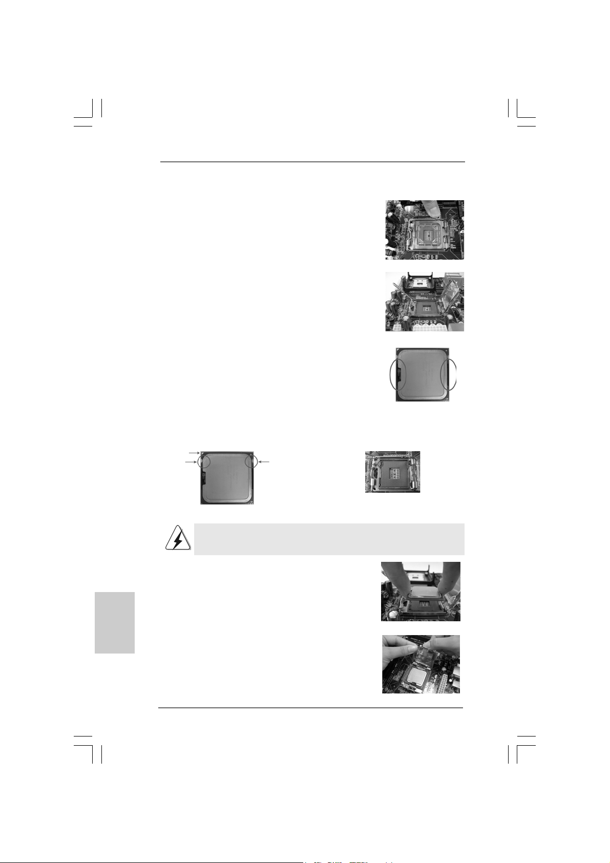
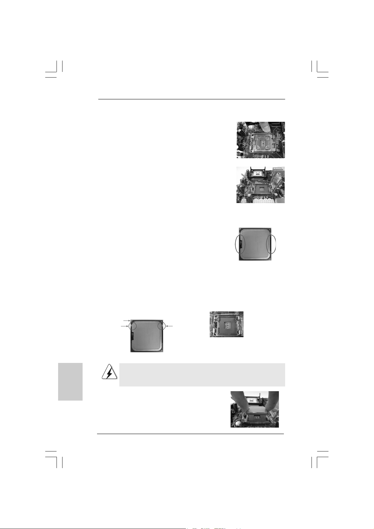
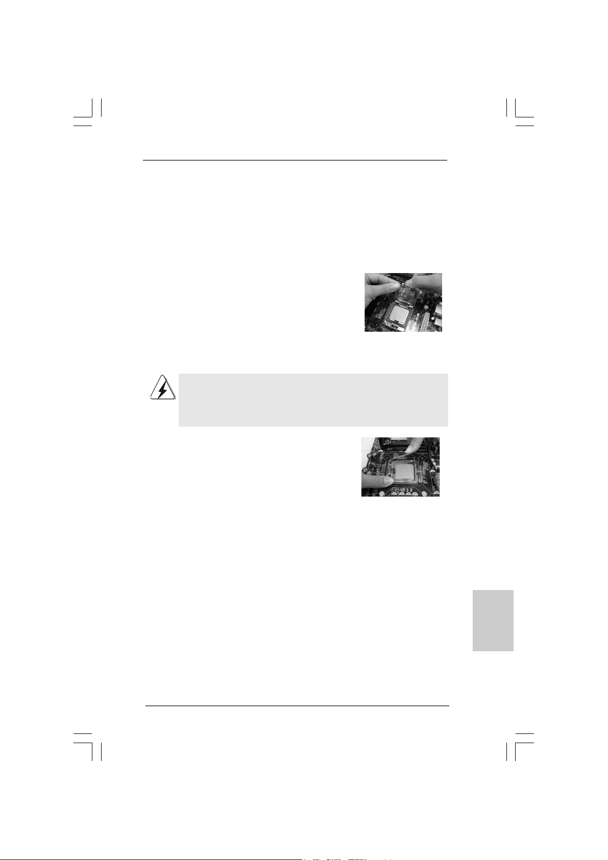
Step 1. Open the socket:
Step 1-1. Disengaging the lever by depressing
down and out on the hook to clear
retention tab.
Step 1-2. Rotate the load lever to fully open po-
sition at approximately 135 degrees.
Step 1-3. Rotate the load plate to fully open po-
sition at approximately 100 degrees.
Step 2. Insert the 775-LAND CPU:
Step 2-1. Hold the CPU by the edges where are
marked with black lines.
Step 2-2. Orient the CPU with IHS (Integrated
Heat Sink) up. Locate Pin1 and the two
orientation key notches.
Pin1
orientation
key notch
orientation
key notch
Pin1
alignment key
black line
black line
alignment key
English
EnglishEnglish
EnglishEnglish
1010
10
1010
775-Pin Socket
775-LAND CPU
For proper inserting, please ensure to match the two orientation key
notches of the CPU with the two alignment keys of the socket.
Step 2-3. Carefully pla ce the CPU into the socket
by using a purely vertical motion.
Step 2-4. Verify that the CPU is within the socket
and properly mated to the orient keys.
Step 3. Remove PnP Cap (Pick and Pla ce Cap):
Use your left hand index finger and thumb to
support the load plate edge, engage PnP cap
with right hand thumb and peel the cap from the
socket while pressing on center of PnP cap to
assist in removal.
ASRock Wolfdale1333-D667 Motherboard
Page 11
1. It is recommended to use the cap tab to handle and avoid kicking
off the PnP cap.
2. This cap must be placed if returning the motherboard for after
service.
Step 4. Close the socket:
Step 4-1. Rotate the load plate onto the IHS.
Step 4-2. While pressing down lightly on load
plate, engage the load lever.
Step 4-3. Secure load lever with load plate tab
under retention tab of load lever.
2.22.2
Installation of CPU Fan and HeatsinkInstallation of CPU Fan and Heatsink
2.2
Installation of CPU Fan and Heatsink
2.22.2
Installation of CPU Fan and HeatsinkInstallation of CPU Fan and Heatsink
For proper installation, please kindly refer to the instruction manuals of your CPU fan
and heatsink.
Below is an example to illustrate the installation of the heatsink for 775-LAND CPU.
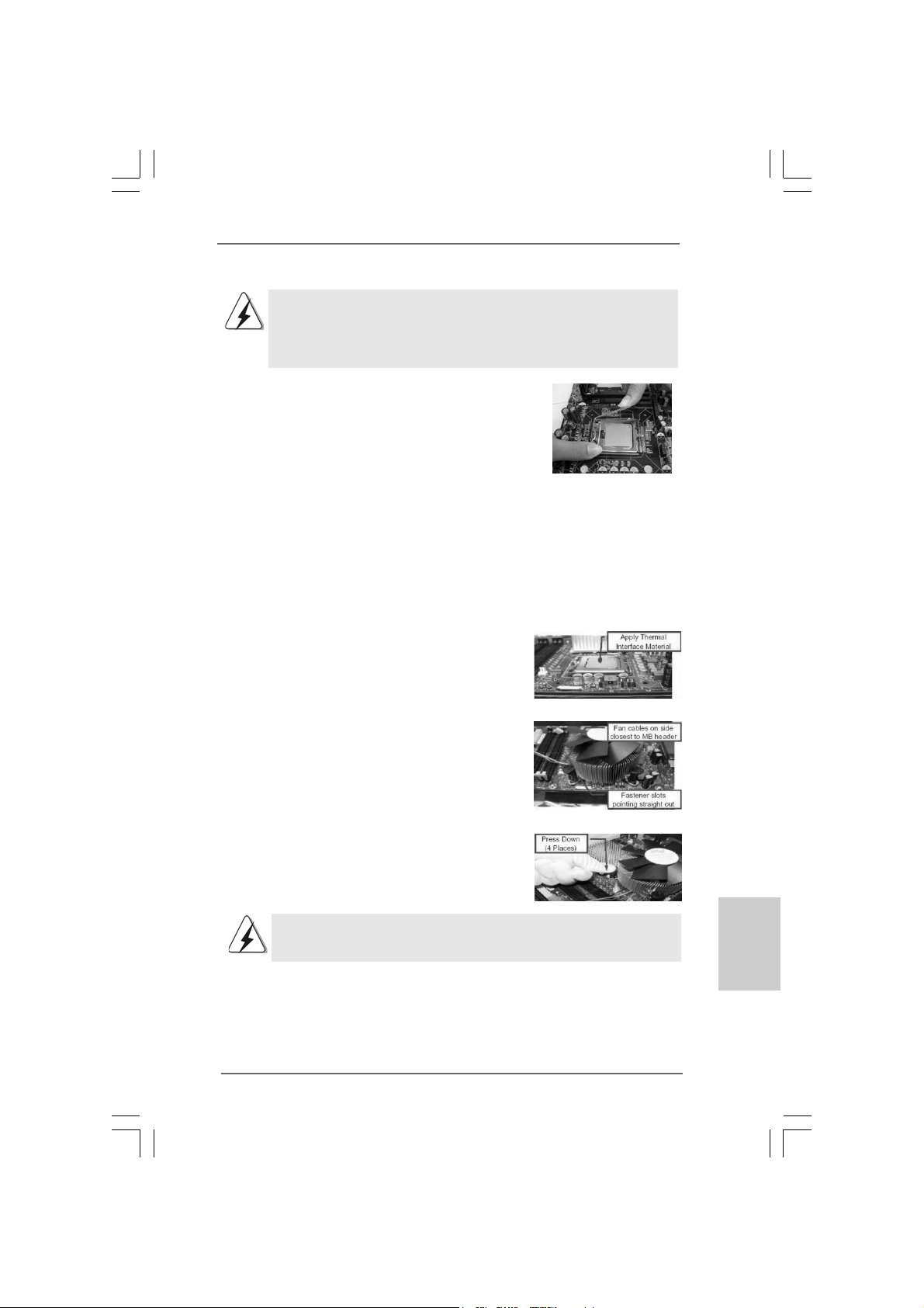
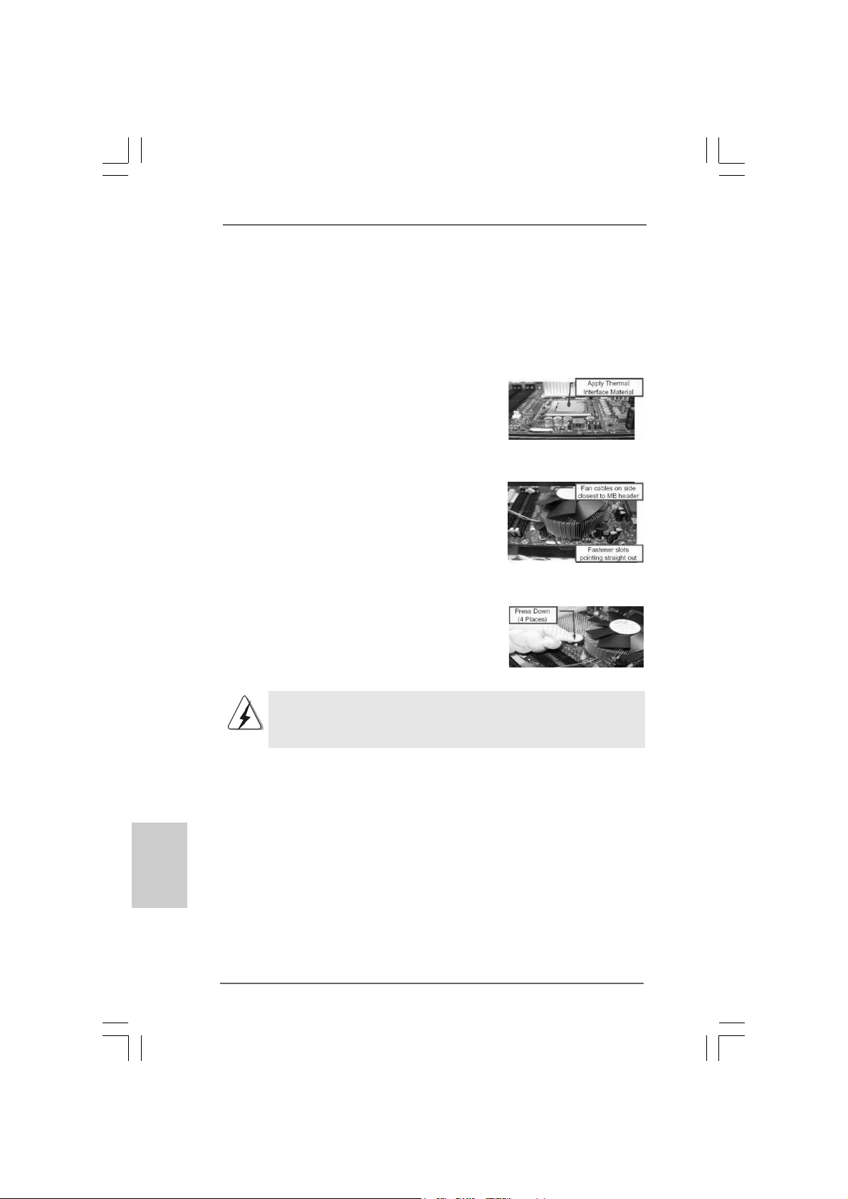
Step 1. Apply thermal interface material onto center
of IHS on the socket surface.
Step 2. Place the heatsink onto the socket. Ensure
fan cables are oriented on side closest to the
CPU fan connector on the motherboard
(CPU_FAN1, see page 2, No. 4).
Step 3. Align fasteners with the motherboard
throughholes.
Step 4. Rotate the fastener clockwise, then press
down on fastener caps with thumb to install
and lock. Repeat with remaining fasteners.
If you press down the fasteners without rotating them clockwise,
the heatsink cannot be secured on the motherboard.
Step 5. Connect fan header with the CPU fan
connector on the motherboard.
Step 6. Secure excess cable with tie-wrap to ensure
cable does not interfere with fan operation or
contact other components.
ASRock Wolfdale1333-D667 Motherboard
1111
11
1111
EnglishEnglish
EnglishEnglish
English
Page 12
2.3 Installation of Memor2.3 Installation of Memor
2.3 Installation of Memor
2.3 Installation of Memor2.3 Installation of Memor
Wolfdale1333-D667 motherboard provides two 240-pin DDRII (Double Data Rate) DIMM
slots, and supports Dual Cha nnel Me mory Technology. For dual channel configuration,
you always need to install two identical (the same brand, speed, size and chip-type)
memory modules in the DD RII DIMM slots to a ctivate Dual Cha nnel Memory Technology.
Otherwise, it will operate at single channel mode.
1. It is not allowed to install a DDR memory module into DDRII slot;
otherwise, this motherboard and DIMM may be damaged.
2. If you install only one memory module or two non-identical memory
modules, it is unable to activate the Dual Channel Memory
Technology.
Installing a DIMMInstalling a DIMM
Installing a DIMM
Installing a DIMMInstalling a DIMM
Please make sure to disconnect power supply before adding or
removing DIMMs or the system components.
Step 1. Unlock a DIMM slot by pressing the retaining clips outward.
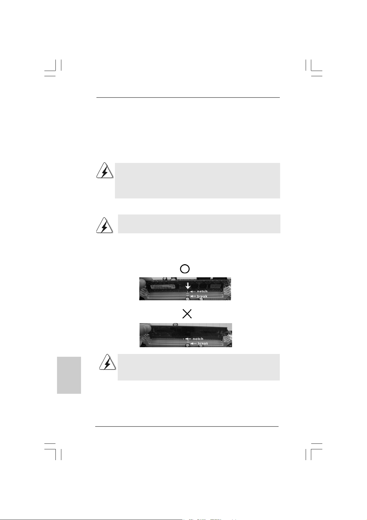
Step 2. Align a DIMM on the slot such that the notch on the DIMM matches the bre a k
on the slot.
y Modules (DIMM)y Modules (DIMM)
y Modules (DIMM)
y Modules (DIMM)y Modules (DIMM)
English
EnglishEnglish
EnglishEnglish
1212
12
1212
The DIMM only fits in one correct orientation. It will cause permanent
damage to the motherboard and the DIMM if you force the DIMM into the
slot at incorrect orientation.
Step 3. Firmly insert the DIMM into the slot until the retaining clips at both ends fully
sna p back in place a nd the DIMM is properly seated.
ASRock Wolfdale1333-D667 Motherboard
Page 13
2.4 Expansion Slots (PCI and PCI Express Slots)2.4 Expansion Slots (PCI and PCI Express Slots)
2.4 Expansion Slots (PCI and PCI Express Slots)
2.4 Expansion Slots (PCI and PCI Express Slots)2.4 Expansion Slots (PCI and PCI Express Slots)
There are 2 PCI slots and 2 PCI Express slots on this motherboard.
PCI slots: PCI slots are used to install expansion cards that have the 32-bit PCI
interface.
PCIE slots: PCIE1 (PCIE x16 slot) is used for PCI Express cards with x16 lane
width graphics cards
PCIE2 (PCIE x1 slot) is used for PCI Express cards with x1 lane
width cards, such as Gigabit LAN card, SATA2 card, etc.
If you install the add-on PCI Express VGA card to PCIE1 (PCIE x16 slot),
the onboard VGA will be disabled. If you install the add-on PCI Express
VGA card to PCIE1 (PCIE x16 slot) and adjust the “Internal Graphics
Mode Select” BIOS option to [Enabled], the onboard VGA will be enabled,
and the primary screen will be onboard VGA.
Installing an expansion cardInstalling an expansion card
Installing an expansion card
Installing an expansion cardInstalling an expansion card
Step 1. Before installing the expansion card, plea se make sure that the power supply
is switched off or the power cord is unplugged. Plea se read the documentation
of the expansion card a nd ma ke necessary hardware
settings for the card before you start the installation.
Step 2. Remove the bracket facing the slot that you intend to use. Keep the screws
for later use.
Step 3. Align the card connector with the slot and press firmly until the card is com-
pletely seated on the slot.
Step 4. Fasten the card to the chassis with screws.
ASRock Wolfdale1333-D667 Motherboard
1313
13
1313
EnglishEnglish
EnglishEnglish
English
Page 14
2.5 Jumpers Setup2.5 Jumpers Setup
2.5 Jumpers Setup
2.5 Jumpers Setup2.5 Jumpers Setup
The illustration shows how jumpers are
setup. When the jumper cap is placed on
pins, the jumper is “Short”. If no jumper cap
is placed on pins, the jumper is “Open”. The
illustration shows a 3-pin jumper whose pin1
and pin2 are “Short” when jumper cap is
placed on these 2 pins.
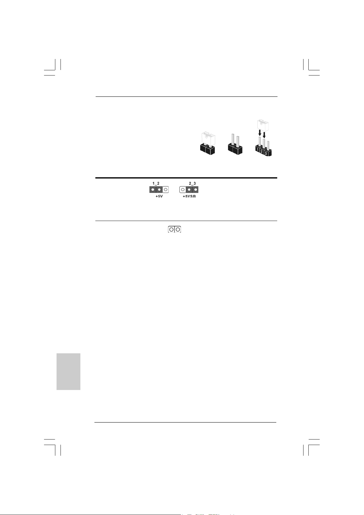
Jumper Setting Description
PS2_USB_PWR1 Short pin2, pin3 to enable
(see p.2 No. 1) +5VSB (standby) for PS/2
Note: To select +5VSB, it requires 2 Amp and higher standby current provided by
power supply.
Clear CMOS
(CLRCMOS1, 2-pin jumper)
(see p.2 No. 9)
Note: CLRCMOS1 allows you to clear the data in CMOS. The data in CMOS includes
system setup information such as system password, date, time, and system
setup parameters. To clear and reset the system parameters to default setup,
please turn off the computer and unplug the power cord from the power
supply. After waiting for 15 seconds, use a jumper cap to short 2 pins on
CLRCMOS1 for 5 seconds.
2-pin jumper
Short Open
or USB wake up events.
English
EnglishEnglish
EnglishEnglish
1414
14
1414
ASRock Wolfdale1333-D667 Motherboard
Page 15
2.6 Onboard Headers and Connectors2.6 Onboard Headers and Connectors
2.6 Onboard Headers and Connectors
2.6 Onboard Headers and Connectors2.6 Onboard Headers and Connectors
Onboard headers and connectors are NOT jumpers. Do NOT place
jumper caps over these headers and connectors. Placing jumper caps
over the headers and connectors will cause permanent damage of the
motherboard!
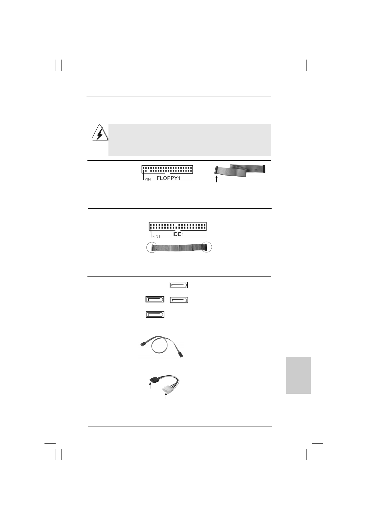
FDD connector
(33-pin FLOPPY1)
(see p.2 No. 19)
the red-striped side to Pin1
Note: Make sure the red-striped side of the cable is plugged into Pin1 side of the
connector.
Primary IDE connector (Blue)
(39-pin IDE1, see p.2 No. 8)
connect the blue end
to the motherboard
connect the black end
to the IDE devices
80-conductor ATA 66/100 cable
Note: Please refer to th e i n struction of your IDE device vendor for the details.
Serial A T AII Connectors These Serial A T AII (SA T AII)
(SATAII_1: see p.2, No. 11) connectors support SA T AII
(SATAII_2: see p.2, No. 15) or SATA hard disk f or internal
(SATAII_3: see p.2, No. 12) storage devices. The current
(SATAII_4: see p.2, No. 13) SATAII interface allows up to
SATAII_1
SATAII_2
SATAII_3
SATAII_4
3.0 Gb/s data tra ns fer rate.
Serial A TA (SA TA) Either end of the SATA data ca ble
Data Cable can be connected to the SATA /
(Optional) SATAII hard disk or the SATAII
connector on the motherboard.
Serial ATA (SATA) Please connect the black end of
Power Cable SATA power cable to the power
(Optional) connector on each drive. Then
connect to the SAT A
HDD power connector
connect to the
power supply
connect the white end of SATA
power cable to the power
connector of the power supply.
EnglishEnglish
EnglishEnglish
English
ASRock Wolfdale1333-D667 Motherboard
1515
15
1515
Page 16
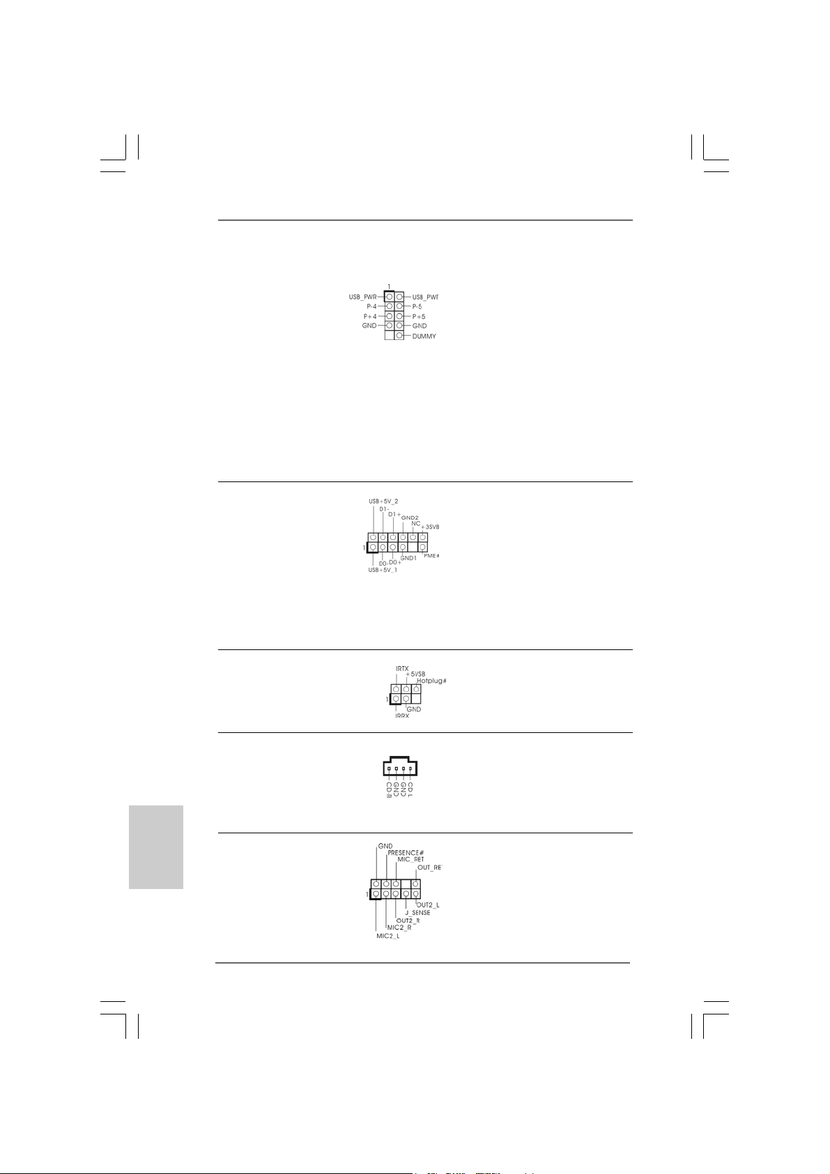
Shared USB 2.0 Header Besides six default USB 2.0
(9-pin USB4_5) ports on the I/O panel, there is
(see p.2 No. 27) one USB 2.0 header on this
motherboard. This USB 2.0
header can support two USB
2.0 ports. The shared USB 2.0
header (USB4_5) is shared with
USB ports 45 on the I/O panel.
When using the front panel USB
ports by attaching the front pa nel
USB cable to USB4_5 header,
the USB ports 45 on the I/O panel
will not be able to function.
WiFi Header This header supports WiFi+AP
(11-pin WIFI) function with ASRock
(see p.2 No. 20) WiFi-802.11g / WiFi-802.1 1n
module, an ea sy-to-use wirele ss
local area network (WLAN)
adapter. It allows you to create a
wireless environment and enjoy the
convenience of wireless network
connectivity.
DeskExpress Hot Plug Dete ction This header supports the Hot
Header Plug detection function for
(5-pin IR1) ASRock DeskExpress.
(see p.2 No. 3)
English
EnglishEnglish
EnglishEnglish
1616
16
1616
Internal Audio Connector This connector allows you
(4-pin CD1) to receive stereo audio input
(CD1: see p.2 No. 23) from sound sources such a s
CD1
a CD-ROM, D VD-ROM, TV
tuner card, or MPEG card.
Front Panel Audio Hea der This is an interface f or front
(9-pin HD_AUDIO1) panel audio cable that allows
(see p.2 No. 22) convenient connection and
control of audio devices.
ASRock Wolfdale1333-D667 Motherboard
Page 17
1. High Definition Audio supports Jack Sensing, but the panel wire on
the chassis must support HDA to function correctly. Please follow the
instruction in our manual and chassis manual to install your system.
2. If you use AC’97 audio panel, please install it to the front panel audio
header as below:
A. Connect Mic_IN (MIC) to MIC2_L.
B. Connect Audio_R (RIN) to OUT2_R and Audio_L (LIN) to OUT2_L.
C. Connect Ground (GND) to Ground (GND).
D. MIC_RET and OUT_RET are for HD audio panel only. You don’t
need to connect them for AC’97 audio panel.
E. Enter BIOS Setup Utility. Enter Advanced Settings, and then select
Chipset Configuration. Set the Front Panel Control option from
[Auto] to [Enabled].
F. Enter Windows system. Click the icon on the lower right hand
taskbar to enter Realtek HD Audio Manager.
For Windows® 2000 / XP / XP 64-bit OS:
Click “Audio I/O”, select “Connector Settings” , choose
“Disable front panel jack detection”, and save the change by
clicking “OK”.
For Windows® VistaTM / VistaTM 64-bit OS:
Click the right-top “Folder” icon , choose “Disable front
panel jack detection”, and save the change by clicking “OK”.
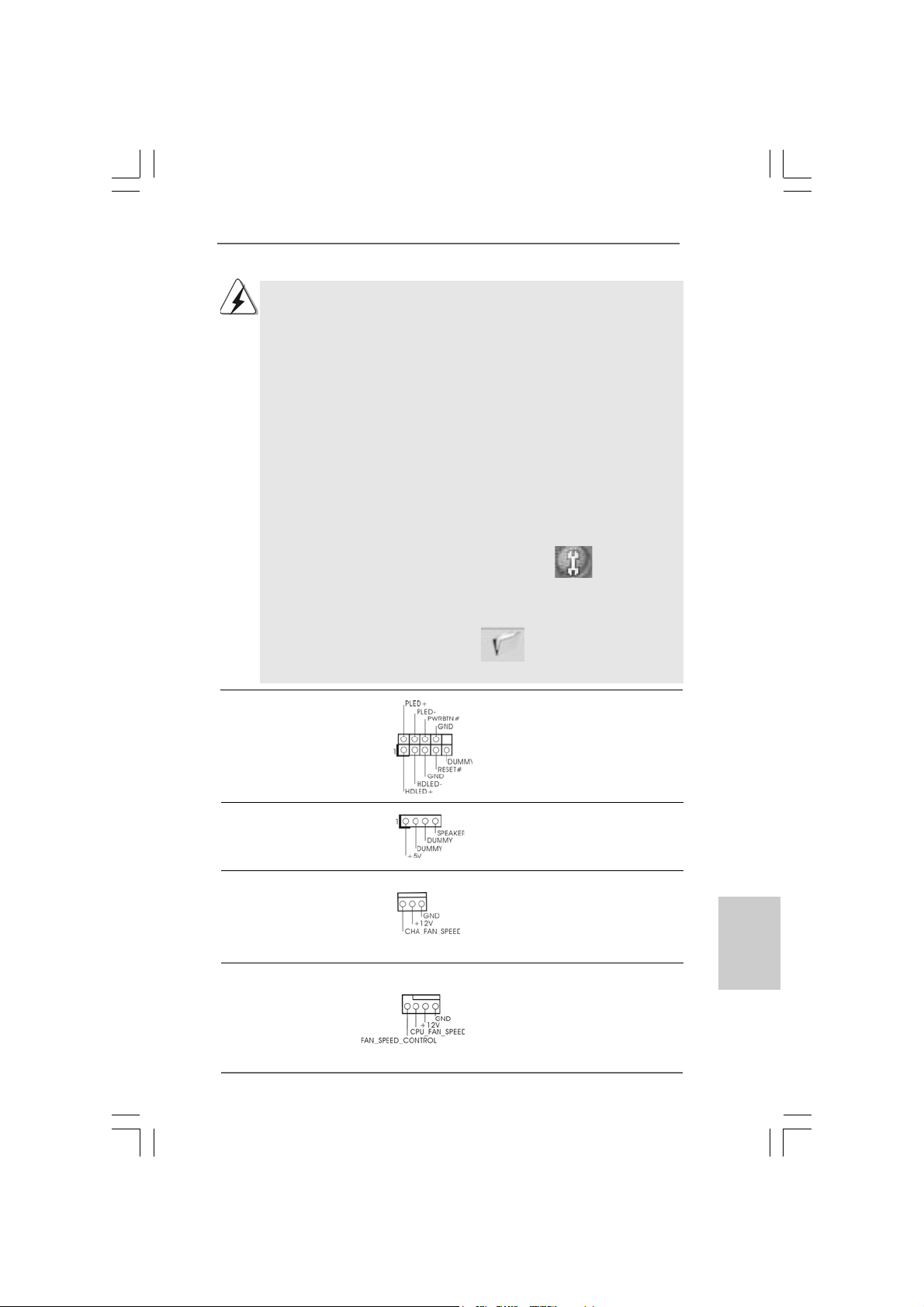
System Panel Hea der This header a ccommodate s
(9-pin PANEL1) several system front pa nel
(see p.2 No. 14) functions.
Chassis Spe aker He ader Please connect the chassis
(4-pin SPEAKER 1) speaker to this hea der.
(see p.2 No. 16)
Chassis Fa n Connector Please connect a chassis fan
(3-pin CHA_FAN1) cable to this connector and
(see p.2 No. 17) match the black wire to the
ground pin.
CPU Fan Connector Please connect a CPU fan cable
(4-pin CPU_FAN1) to this connector and match
(see p.2 No. 4) the black wire to the ground pin.
4 3 2 1
ASRock Wolfdale1333-D667 Motherboard
1717
17
1717
EnglishEnglish
EnglishEnglish
English
Page 18
Though this motherboard provides 4-Pin CPU fan (Quiet Fan) support, the 3-Pin
CPU fan still can work successfully even without the fan speed control function.
If you plan to connect the 3-Pin CPU fan to the CPU fan connector on this
motherboard, please connect it to Pin 1-3.
Pin 1-3 Connected
3-Pin Fan Installation
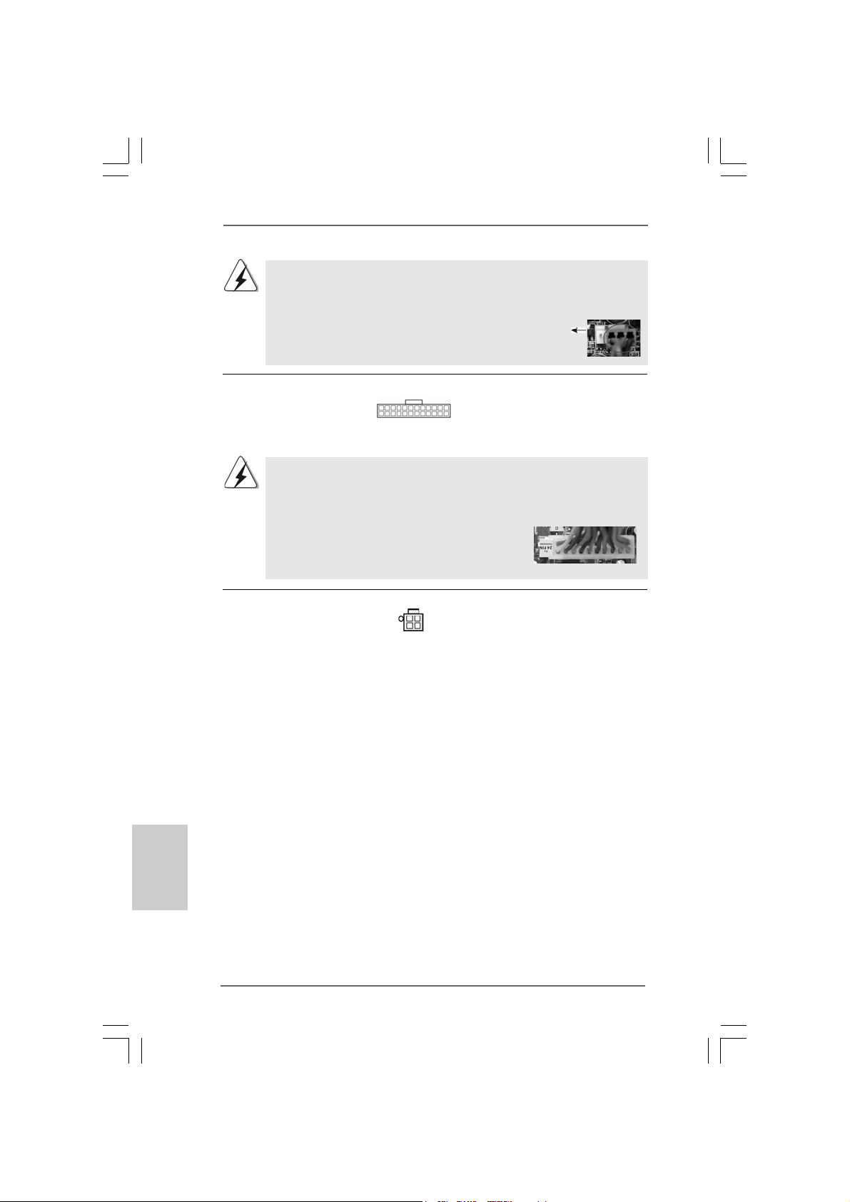
ATX Power Conne ctor Please connect an A TX power
(24-pin ATXPWR1) supply to this connector.
(see p.2, No. 26)
Though this motherboard provides 24-pin ATX power connector, it can still work
if you adopt a traditional 20-pin ATX power supply. To use the 20-pin ATX power
supply, please plug your power supply along with Pin 1 and Pin 13.
24 13
12 1
24 13
20-Pin ATX Power Supply Installation
12 1
ATX 12V Connector Please note that it is necessary
(4-pin ATX12V1) to connect a power supply with
(see p.2 No. 2) ATX 12V plug to this connector
so that it can provides sufficient
power. Failing to do so will cause
the failure to power up.
English
EnglishEnglish
EnglishEnglish
1818
18
1818
ASRock Wolfdale1333-D667 Motherboard
Page 19
tion
13
1
2.72.7
SASA
TT
2.7
2.72.7
Before installing SATAII hard disk to your computer, please carefully read below
SATAII hard disk setup guide. Some default setting of SATAII hard disks may not
be at SATAII mode, which operate with the best performance. In order to enable
SATAII function, please follow the below instruction with different vendors to
correctly adjust your SATAII hard disk to SATAII mode in advance; otherwise, your
SATAII hard disk may fail to run at SATAII mode.
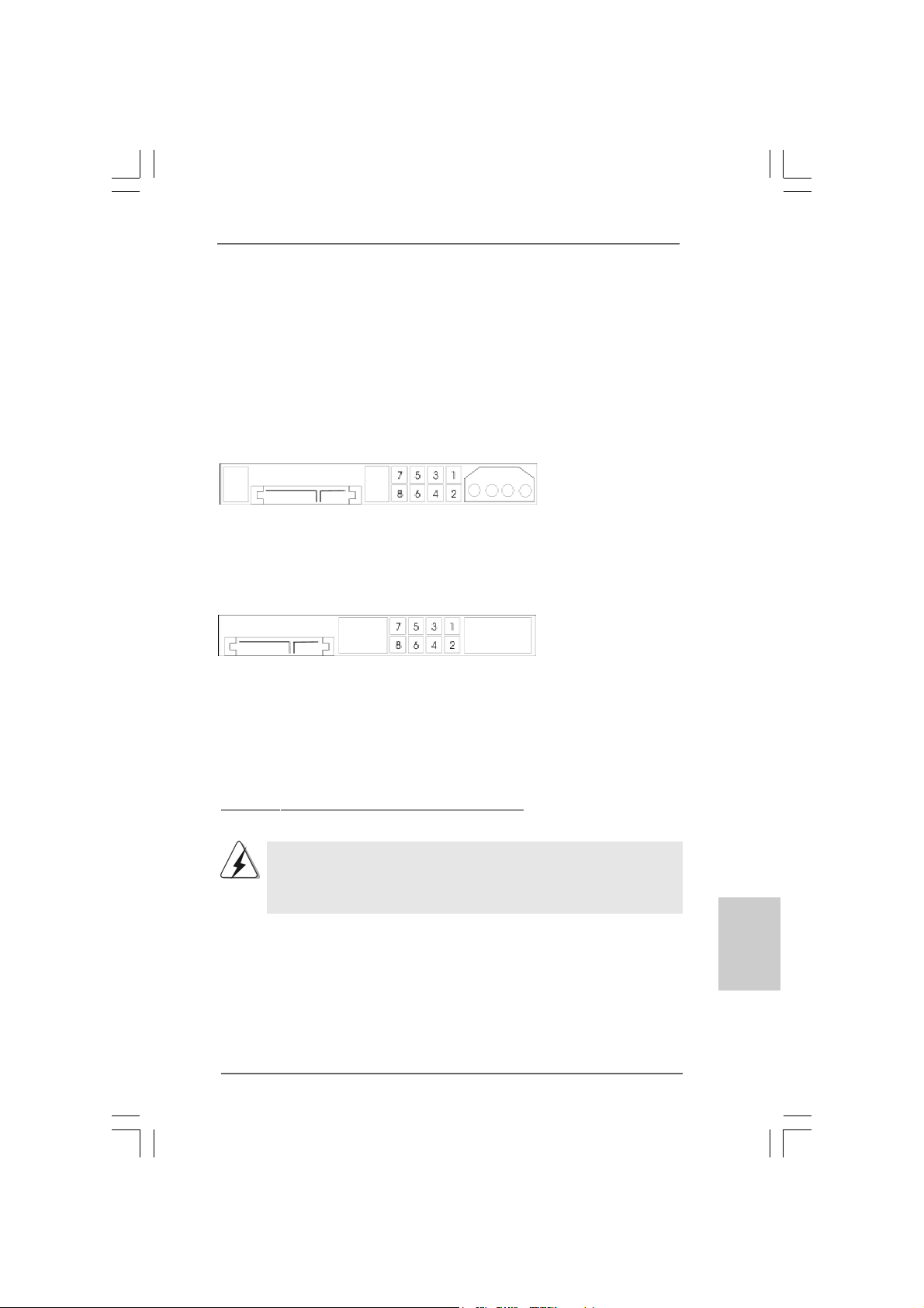
Western Digital
If pin 5 and pin 6 are shorted, SATA 1.5Gb/s will be enabled.
On the other hand, if you want to enable SATAII 3.0Gb/s, please remove the
jumpers from pin 5 and pin 6.
SAMSUNG
If pin 3 and pin 4 are shorted, SATA 1.5Gb/s will be enabled.
On the other hand, if you want to enable SATAII 3.0Gb/s, please remove the
jumpers from pin 3 and pin 4.
AII Hard Disk Setup GuideAII Hard Disk Setup Guide
SA
T
AII Hard Disk Setup Guide
SASA
TT
AII Hard Disk Setup GuideAII Hard Disk Setup Guide
HITACHI
Please use the Feature Tool, a DOS-bootable tool, for changing various ATA
features. Please visit HITACHI’s website for details:
http://www.hitachigst.com/hdd/support/download.htm
The above examples are just for your reference. For different SATAII hard
disk products of different vendors, the jumper pin setting methods may not
be the same. Please visit the vendors’ website for the updates.
ASRock Wolfdale1333-D667 Motherboard
1919
19
1919
EnglishEnglish
EnglishEnglish
English
Page 20
2.82.8
Serial ASerial A
2.8
Serial A
2.82.8
Serial ASerial A
Installation Installation
Installation
Installation Installation
This motherboard adopts Intel® ICH7 south bridge chipset that supports Serial AT A
(SATA) / Serial AT AII (SATAII) hard disks. Y ou may in stall SAT A / SATAII hard disks on
this motherboard for internal storage devices. This section will guide you to install the
SATA / SAT AII hard disk s.
STEP 1: Install the SATA / SAT AII hard disk s into the drive bays of your chassis.
STEP 2: Connect the SATA power ca ble to the SAT A / SATAII hard disk.
STEP 3: Connect one end of the SATA data cable to the motherboard’s SAT AII
connector.
STEP 4: Connect the other end of the SATA data cable to the SAT A / SATAII hard
disk.
2.92.9
Driver Installation GuideDriver Installation Guide
2.9
Driver Installation Guide
2.92.9
Driver Installation GuideDriver Installation Guide
To install the drivers to your system, plea se insert the support CD to your optical drive
first. Then, the drivers compatible to your system ca n be auto-detected and listed on
the support CD driver page. Please follow the order from up to bottom side to install
those required drivers. Therefore, the drivers you install ca n work properly .
2.102.10
Untied Overclocking TUntied Overclocking T
2.10
Untied Overclocking T
2.102.10
Untied Overclocking TUntied Overclocking T
This motherboard supports Untied Overclocking Technology, which means during
overclocking, FSB enjoys better margin due to fixed PCI / PCIE buses. Before you
enable Untied Overclocking function, plea se enter “Overclock Mode” option of BIOS setup
to set the selection from [Auto] to [CPU, PCIE, Async.]. Therefore, CPU FSB is untied
during overclocking, but PCI / PCIE buses are in the fixed mode so that FSB can operate
under a more stable overclocking environment.
TT
A (SAA (SA
T
A (SA
TT
A (SAA (SA
TT
A) / Serial AA) / Serial A
T
A) / Serial A
TT
A) / Serial AA) / Serial A
echnologyechnology
echnology
echnologyechnology
TT
AII (SAAII (SA
T
AII (SA
TT
AII (SAAII (SA
TT
AII) Hard DisksAII) Hard Disks
T
AII) Hard Disks
TT
AII) Hard DisksAII) Hard Disks
English
EnglishEnglish
EnglishEnglish
2020
20
2020
Please refer to the warning on page 6 for the possible overclocking risk
before you apply Untied Overclocking Technology.
ASRock Wolfdale1333-D667 Motherboard
Page 21
3. BIOS Information3. BIOS Information
3. BIOS Information
3. BIOS Information3. BIOS Information
The Flash Memory on the motherboard stores BIOS Setup Utility. When you start up
the computer, please press <F2> during the Power-On-Self-Test (POST) to enter
BIOS Setup utility; otherwise, POST continues with its test routines. If you wish to
enter BIOS Setup after POST, please restart the system by pressing <Ctl> + <Alt> +
<Delete>, or pressing the reset button on the system chassis. The BIOS Setup program is designed to be user-friendly. It is a menu-driven program, which allows you to
scroll through its various sub-menus and to select among the predetermined choices.
For the detailed information about BIOS Setup, please refer to the User Manual (PDF
file) contained in the Support CD.
4. Software Suppor4. Software Suppor
4. Software Suppor
4. Software Suppor4. Software Suppor
This motherboard supports various Microsoft® Windows® operating systems: 2000 /
XP / XP 64-bit / VistaTM / Vista
contains necessary drivers and useful utilities that will enhance motherboard features.
To begin using the Support CD, insert the CD into your CD-ROM drive. It will display
the Main Menu automatically if “AUTORUN” is enabled in your computer. If the Main
Menu does not appear automatically, locate and double-click on the file “ASSETUP.
EXE” from the BIN folder in the Support CD to display the menus.
TM
64-bit. The Support CD that ca me with the motherboard
t CD informationt CD information
t CD information
t CD informationt CD information
EnglishEnglish
EnglishEnglish
English
ASRock Wolfdale1333-D667 Motherboard
2121
21
2121
Page 22
1. Einführung1. Einführung
1. Einführung
1. Einführung1. Einführung
Wir danken Ihnen für den Kauf des ASRock Wolfdale1333-D667 Motherboard, ein
zuverlässiges Produkt, welches unter den ständigen, strengen Qualitätskontrollen von
ASRock gefertigt wurde. Es bietet Ihnen exzellente Leistung und robustes De sign, gemäß
der Verpflichtung von ASRock zu Qualität und Halbarkeit.
Diese Schnellinstallationsanleitung führt in das Motherboard und die schrittweise
Installation ein. Details über das Motherboard finden Sie in der
Bedienungsanleitung auf der Support-CD.
Da sich Motherboard-Spezifikationen und BIOS-Software verändern
können, kann der Inhalt dieses Handbuches ebenfalls jederzeit geändert
werden. Für den Fall, dass sich Änderungen an diesem Handbuch
ergeben, wird eine neue Version auf der ASRock-Website, ohne weitere
Ankündigung, verfügbar sein. Die neuesten Grafikkarten und unterstützten
CPUs sind auch auf der ASRock-Website aufgelistet.
ASRock-Website: http://www.asrock.com
Wenn Sie technische Unterstützung zu Ihrem Motherboard oder spezifische
Informationen zu Ihrem Modell benötigen, besuchen Sie bitte unsere
Webseite:
www.asrock.com/support/index.asp
1.1 Kartoninhalt
ASRock Wolfdale1333-D667 Motherboard
(Micro ATX-Formfaktor: 24.4 cm x 22.1 cm; 9.6 Zoll x 8.7 Zoll)
ASRock Wolfdale1333-D667 Schnellinstallationsa nle itung
ASRock Wolfdale1333-D667_ Support-CD
Ein 80-adriges Ultra-A T A 66/100 IDE-Fla chbandka bel
Ein Flachba ndkabel für e in 3,5-Zoll-Diskettenlaufwerk
Ein Seriell-ATA- (SA T A) Datenka bel (Option)
Ein Seriell-ATA (SAT A) Festplattennetzka bel (Option)
Ein ASRock 6CH I/O Plus Shield
Deutsch
DeutschDeutsch
DeutschDeutsch
2222
22
2222
ASRock Wolfdale1333-D667 Motherboard
Page 23
1.21.2
SpezifikationenSpezifikationen
1.2
Spezifikationen
1.21.2
SpezifikationenSpezifikationen
Plattform - Micro ATX-Formfaktor: 24.4 cm x 22.1 cm; 9.6 Zoll x 8.7 Zoll
CPU - LGA 775 für Intel® Dual Core CoreTM 2 Extreme- / CoreTM 2
Duo- / Pentium® Dual Core- / Celeron®-Prozessoren, Dual Core
Wolfdale-Prozessoren werden unterstützt
- Kompatibilität mit allen Zentraleinheiten (CPU) FSB1333/1066/
800/533MHz außer Quadrangel Kerne (siehe VORSICHT 1)
- Unterstützt Hyper-Threading-Technologie
(siehe VORSICHT 2)
- Unterstützt Untied-Übertaktungstechnologie
(siehe VORSICHT 3)
- Unterstützt EM64T -CPU
Chipsatz - Northbridge: Intel® 945GC A2
- Southbridge: Intel® ICH7
Speicher - Unterstützung von Dual-Kanal-DDRII-Speichertechnologie
(siehe VORSICHT 4)
- 2 x Steckplätze für DDRII
- Unterstützt DDRII667/533 (siehe VORSICHT 5)
- Max. 4GB (siehe VORSICHT 6)
Hybrid Booster - Schrittloser CPU-Frequenz-Kontrolle (siehe VORSICHT 7)
- ASRock U-COP (siehe VORSICHT 8)
- Boot Failure Guard (B.F.G. – Systemstartfehlerschutz)
Erweiterungs- - 1 x PCI Express x16-Steckplätze
steckplätze - 1 x PCI Express x1-Steckplätze
- 2 x PCI -Steckplätze
Onboard-VGA - Intel® Graphics Media Accelerator 950
- Pixel Shader 2.0, DX9.0 VGA
- Maximal gemeinsam genutzter Speicher 224MB
(siehe VORSICHT 9)
Audio - 5.1 CH High Definition Audio (Realtek ALC660V D Audio Code c)
LAN - Realtek PCIE x1 LAN 8101E
- Speed: 10/100 Ethernet
- Unterstützt W a ke-On-LAN
E/A-Anschlüsse ASRock 6CH I/O Plus
an der - 1 x PS/2 Mouse Port
Rückseite - 1 x PS/2 Keyboard Port
- 1 x Serieller port: COM 1
- 1 x VGA Port
- 1 x Parallel Port (ECP/EPP Support)
DeutschDeutsch
DeutschDeutsch
Deutsch
ASRock Wolfdale1333-D667 Motherboard
2323
23
2323
Page 24
Deutsch
DeutschDeutsch
DeutschDeutsch
- 6 x Ready-to-Use USB 2.0 Ports
- 1 x RJ-45 Port
- Audioanschlüsse: Line In / Line Out / Mikrofon
Anschlüsse - 4 x SATAII-Anschlüsse, unterstützt bis 3.0 Gb/s
Datenübertragungsrate (U nterstützt keine “RAID”- und “Hot Plug”-Funktionen) (siehe VORSICHT 10)
- 1 x ATA100 IDE-An schlüsse (U nterstützt bis 2 IDE-Geräte)
- 1 x FDD-Anschlüsse
- 1 x DeskExpress heißer Stecker Detektionskopf
- CPU/Gehäuse-Lüfteranschluss
- 24-pin A TX-Netz-Header
- 4-pin anschluss für 12V-ATX-Netzteil
- Interne Audio-Anschlüsse
- Anschluss für Audio auf der Gehäusevorderseite
- 1 x USB 2.0 Buchse (unterstützt 2 USB 2.0 Ports; geteilt mit
USB45 Ports am E/A-An schlussfeld) (siehe VORSICHT 11)
- 1 x WiFi Header (siehe VORSICHT 12)
BIOS - 4Mb AMI BIOS
- AMI legal BIOS mit U nterstützung für “Plug and Play”
- ACPI 1.1-Weckfunktionen
- JumperFree-Modus
- SMBIOS 2.3.1
Support-CD - T reiber , Dienstprogra mme, Antivirussoftware
(Probeversion)
Hardware Monitor - Überwachung der CPU-T emperatur
- Motherboardtemperaturerkennung
- Drehzahlmessung für CPU-Lüfter
- Drehzahlmessung für Gehäuselüfter
- CPU-Lüftergeräuschdämpfung
- Spannungsüberwachung: +12V, +5V, +3.3V, Vcore
Betriebssysteme - Unterstützt Microsoft® Windows® 2000 / XP / XP 64-Bit /
VistaTM / Vista
Zertifizierungen - FCC, CE, WHQL
TM
64-Bit
2424
24
2424
ASRock Wolfdale1333-D667 Motherboard
Page 25
WARNUNG
Beachten Sie bitte, dass Overclocking, einschließlich der Einstellung im BIOS, Anwenden
der Untied Overclocking-Technologie oder Verwenden von Overclocking-Werkzeugen von
Dritten, mit einem gewissen Risiko behaftet ist. Overclocking kann sich nachteilig auf die
Stabilität Ihres Systems auswirken oder sogar Komponenten und Geräte Ihres Systems
beschädigen. Es geschieht dann auf eigene Gefahr und auf Ihre Kosten. Wir übernehmen
keine Verantwortung für mögliche Schäden, die aufgrund von Overclocking verursacht
wurden.
VORSICHT!
1. FSB1333-CPU wird nach Uhrzeitmode operatieren. In diese Situation
wird PCIE Frequenz auch nach Uhrzeitmode zu 115MHz.
2. Die Einstellung der “Hyper-Threading Technology”, finden Sie auf
Seite 28 des auf der Support-CD enthaltenen Benutzerhandbuches
beschrieben.
3. Dieses Motherboard unterstützt die Untied-Übertaktungstechnologie.
Unter “Entkoppelte Übertaktungstechnologie” auf Seite 39 finden Sie
detaillierte Informationen.
4. Dieses Motherboard unterstützt Dual-Kanal-Speichertechnologie. Vor
Implementierung der Dual-Kanal-Speichertechnologie müssen Sie die
Installationsanleitung für die Speichermodule auf Seite 31 zwecks
richtiger Installation gelesen haben.
5. Die unterstützten Arbeitsspeicherfrequenzen und die entsprechende
CPU FSB-Frequenz entnehmen Sie bitte der nachstehenden Tabelle.
CPU FSB-Frequenz Unterstützte Arbeitsspeicherfrequenz
1333 DDRII533*, DDRII667
1066 DDRII533, DDRII667
800 DDRII400, DDRII533, DDRII667
533 DDRII400, DDRII533
* Bei Verwendung einer FSB1333-CPU auf diesem Motherboard läuft es
mit DDRII500, wenn Sie ein DDRII533-Speichermodul verwenden.
6. Aufgrund von Chipset-Einschränkungen könnte unter Windows
2000, Windows® XP, Windows® XP 64-Bit, Windows® VistaTM und
Windows® Vista
Speichergröße unterhalb von 4 GB liegen.
7. Obwohl dieses Motherboard stufenlose Steuerung bietet, wird
Overclocking nicht empfohlen. Frequenzen, die über den für den
jeweiligen Prozessor vorgesehenen liegen, können das System
instabil werden lassen oder die CPU beschädigen.
8. Wird eine Überhitzung der CPU registriert, führt das System einen
automatischen Shutdown durch. Bevor Sie das System neu starten, prüfen
Sie bitte, ob der CPU-Lüfter am Motherboard richtig funktioniert, und
stecken Sie bitte den Stromkabelstecker aus und dann wieder ein. Um
die Wärmeableitung zu verbessern, bitte nicht vergessen, etwas
Wärmeleitpaste zwischen CPU und Kühlkörper zu sprühen.
TM
64-Bit die für das System reservierte
®
DeutschDeutsch
DeutschDeutsch
Deutsch
ASRock Wolfdale1333-D667 Motherboard
2525
25
2525
Page 26
9. Die Maximalspeichergröße ist von den Chipshändler definiert und
umgetauscht. Bitte überprüfen Sie Intel® website für die neuliche
Information.
10. Bevor Sie eine SATA II Festplatte mit dem SATA II Anschluss verbinden,
lesen Sie bitte die “Anleitung zur SATA II Festplatteneinrichtung“ auf
Seite 38, um Ihre SATA II Festplatte in den SATA II Modus
umzuschalten. SATA-Festplatten können Sie auch direkt mit dem SATA
II-Anschluss verbinden.
11. Das Power Management für USB 2.0 arbeitet unter Microsoft
Windows® VistaTM 64-Bit / VistaTM / XP 64-Bit / XP SP1 oder SP2/2000
SP4 einwandfrei.
12. WiFi Sockel unterstützt WiFi+AP Funktion mit ASRock WiFi-802.11g /
WiFi-802.11n Modul, einem einfach zu bedienenden Wireless Local
Area Network (WLAN) Adapter. Damit sind Sie in der Lage, ein
drahtloses Netzwerk aufzubauen und die Vorzüge drahtloser
Anschlussmöglichkeiten zu genießen. Für Verfügbarkeit des ASRock
WiFi-802.11g / WiFi-802.11n Moduls, siehe bitte unsere Webseite.
ASRock Webseite http://www.asrock.com
®
Deutsch
DeutschDeutsch
DeutschDeutsch
2626
26
2626
ASRock Wolfdale1333-D667 Motherboard
Page 27
2. Installation2. Installation
2. Installation
2. Installation2. Installation
Sicherheitshinweise vor der MontageSicherheitshinweise vor der Montage
Sicherheitshinweise vor der Montage
Sicherheitshinweise vor der MontageSicherheitshinweise vor der Montage
Bitte nehmen Sie die folgende Sicherheitshinweise zur Kenntnis, bevor Sie das
Motherboard einbauen oder Veränderungen an den Einstellungen vornehmen.
1. Trennen Sie das System vom Stromnetz, bevor Sie eine ystemkomponente
berühren, da es sonst zu schweren Schäden a m Motherboard oder den
sonstigen internen, bzw. externen omponenten kommen kann.
2. Um Schäden aufgrund von statischer Elektrizität zu vermeiden, das
Motherboard NIEMALS auf einen Teppich o.ä.legen. Denken Sie außerem
daran, immer ein geerdetes Armband zu tragen oder ein geerdetes Objekt
aus Metall zu berühren, bevor Sie mit Systemkomponenten hantieren.
3. Halten Sie Komponenten immer an den Rändern und vermeiden Sie
Berührungen mit den ICs.
4. Wenn Sie Komponenten ausbauen, legen Sie sie immer auf eine
antistatische Unterlage, oder zurück in die Tüte, mit der die Komponente
geliefert wurde.
5. Wenn Sie das Motherboard mit den Schrauben an dem Computergehäuse
befestigen, überziehen Sie bitte die Schrauben nicht! Das Motherboard kann
sonst beschädigt werden.
2.1 CPU Installation2.1 CPU Installation
2.1 CPU Installation
2.1 CPU Installation2.1 CPU Installation
Für die Installation des Intel 775-Pin CPU
führen Sie bitte die folgenden Schritte durch.
(Ladeplatte)
(Kontaktreihe)
(Sockel)
775-Pin Sockel Übersicht
Bevor Sie die 775-Pin CPU in den Sockel sitzen, prüfen Sie bitte,
ob die CPU-Oberfläche sauber ist und keine der Kontakte verbogen
sind. Setzen Sie die CPU nicht mit Gewalt in den Sockel, dies kann
die CPU schwer beschädigen.
ASRock Wolfdale1333-D667 Motherboard
2727
27
2727
DeutschDeutsch
DeutschDeutsch
Deutsch
Page 28
Schritt 1. Öffnen Sie den Sockel:
Schritt 1-1. Öffnen Sie den Hebel, indem
Sie ihn nach unten drücken und
aushaken.
Schritt 1-2. Drehen Sie den Ladehebel, bis
er in geöffneter Position steht,
ca. 135 Grad.
Schritt 1-3. Drehen Sie die Ladeplatte, bis
sie in geöffneter Position steht,
ca. 100 Grad.
Schritt 2. 775-Pin CPU einstecken:
Schritt 2-1. Halten Sie die CPU an den mit
schwarzen Linien
gekennzeichneten Seiten.
Schritt 2-2. Halten Sie das Teil mit dem IHS
(Integrated Heat Sink –
integrierter Kühlkörper) nach
oben. Suchen Sie Pin 1 und die
zwei
Orientierungseinkerbungen.
Pin1
Orientierungskerbe
Ausrichtungsmarkierung
Orientierungskerbe
Pin1
Schwarze Linie
775-Pin Sockel
Schwarze Linie
Ausrichtungsmarkierung
Deutsch
DeutschDeutsch
DeutschDeutsch
2828
28
2828
775-Pin CPU
Um die CPU ordnungsgemäß einsetzen zu können, richten Sie die
zwei Orientierungskerben der CPU mit den beiden Markierungen des
Sockels aus.
Schritt 2-3. Drücken Sie die CPU vorsichtig
in vertikaler Richtung in den
Sockel.
ASRock Wolfdale1333-D667 Motherboard
Page 29
Schritt 2-4. Prüfen Sie, dass die CPU
ordnungsgemäß im Sockel sitzt
und die Orientierungskerben
einwandfrei in den
entsprechenden Auskerbungen
sitzen.
Schritt 3. PnP-Kappe entfernen (Pick and Place-Kappe):
Halten Sie den Rand der Ladeplatte mit
Zeigefinger und Daumen Ihrer linken Hand,
halten Sie die PnP-Kappe mit dem Daumen
der rechten Hand und ziehen Sie die Kappe
vom Sockel während Sie auf die Mitte der
Kappe drücken, um ein Entfernen zu
erleichtern.
1. Verwenden Sie beim Entfernen die Kappenlasche und vermeiden
Sie ein Abreißen der PnP-Kappe.
2. Diese Kappe muss angebracht werden, falls Sie das Motherboard
zur Reparatur bringen.
Schritt 4. Sockel schließen:
Schritt 4-1. Drehen Sie die Ladeplatte auf
den Kühlkörper (IHS).
Schritt 4-2. Drücken Sie leicht auf die
Ladeplatte und schließen Sie
den Ladehebel.
Schritt 4-3. Sichern Sie Ladehebel und
Ladeplatte mithilfe des
Hebelverschlusses.
ASRock Wolfdale1333-D667 Motherboard
2929
29
2929
DeutschDeutsch
DeutschDeutsch
Deutsch
Page 30
2.22.2
Installation des CPU-Lüfters und KühlkörpersInstallation des CPU-Lüfters und Kühlkörpers
2.2
Installation des CPU-Lüfters und Kühlkörpers
2.22.2
Installation des CPU-Lüfters und KühlkörpersInstallation des CPU-Lüfters und Kühlkörpers
Für Installationshinweise, siehe Betriebsanleitung Ihres CPU-Lüfters und
Kühlkörpers.
Unten stehend ein Beispiel zur Installation eines Kühlkörpers für den 775-Pin CPU.
Deutsch
DeutschDeutsch
DeutschDeutsch
Schritt 1. Geben Sie Wärmeleitmaterial auf die Mitte
des IHS, auf die Sockeloberfläche.
Schritt 2. Setzen Sie den Kühlkörper auf den Sockel.
Prüfen Sie, dass die Lüfterkabel auf der
Seite am nächsten zum CPU-LüfterAnschluss des Motherboards verlaufen
(CPU_FAN1, siehe Seite 2, Nr. 4).
Schritt 3. Richten Sie Verbindungselemente und
Löcher im Motherboard aus.
Schritt 4. Drehen Sie die Verbindungselemente im
Uhrzeigersinn und drücken Sie mit dem
Daumen auf die Kappen der Elemente zum
Feststellen. Wiederholen Sie dies mit den
anderen Verbindungselementen.
Wenn Sie die Verbindungselemente nur drücken, ohne sie im
Uhrzeigersinn zu drehen, wird der Kühlkörper nicht ordnungsgemäß
am Motherboard befestigt.
Schritt 5. Schließen Sie den Lüfter an den CPU-
Lüfteranschluss des Motherboards.
Schritt 6. Befestigen Sie überschüssiges Kabel mit
Band, um eine Störung des Lüfters oder
Kontakt mit anderen Teilen zu vermeiden.
(Tragen Sie Wärmeleitmaterial auf. )
(Lüfterkabel auf der Seite am nächsten
zum Anschluss des Motherboards)
(Schlitze der Verbindungselemente
nach außen)
(Nach unten drücken (4 Stellen))
3030
30
3030
ASRock Wolfdale1333-D667 Motherboard
Page 31

2.3 Installation der Speichermodule (DIMM)2.3 Installation der Speichermodule (DIMM)
2.3 Installation der Speichermodule (DIMM)
2.3 Installation der Speichermodule (DIMM)2.3 Installation der Speichermodule (DIMM)
Das Wolfdale1333-D667 Motherboard bietet zwei 240polige DD RII (Double Data Rate)
DIMM-Steckplätze und unterstützt Zweika nal-Speicherte chnologie. Es müssen immer
zwei identische Speichermodule (selbe Marke, Ge schwindigkeit, Größe und Chip-Art)
in den DDRII DIMM-Steckplätzen installiert werden, um die Zweika nalSpeichertechnologie zu aktivieren. Andernfalls erf olgt der Betrieb im Einka n al-Modus.
1. s ist nicht zulässig, DDR in einen DDRII Steckplatz zu installieren;
andernfalls könnten Motherboard und DIMMs beschädigt werden.
2. W enn Sie nur e in Speichermodul oder zwei nicht identische Speichermodule
installieren, kann die Zweikanal-Speichertechnologie nicht aktiviert werden.
Einsetzen eines DIMM-ModulsEinsetzen eines DIMM-Moduls
Einsetzen eines DIMM-Moduls
Einsetzen eines DIMM-ModulsEinsetzen eines DIMM-Moduls
Achten Sie darauf, das Netzteil abzustecken, bevor Sie DIMMs oder
Systemkomponenten hinzufügen oder entfernen.
Schritt 1: Öffnen Sie einen DIMM-Slot, indem Sie die seitlichen Clips nach außen
drücken.
Schritt 2: Richten Sie das DIMM-Modul so über de m Slot aus, dass da s Modul mit
der Kerbe in den Slot passt.
Die DIMM-Module passen nur richtig herum eingelegt in die
Steckplätze. Falls Sie versuchen, die DIMM-Module mit Gewalt falsch
herum in die Steckplätze zu zwingen, führt dies zu dauerhaften
Schäden am Mainboard und am DIMM-Modul.
Schritt 3: Drücken Sie die DIMM-Module fest in die Steckplätze, so dass die
Halteklammern a n be iden Enden des Moduls einschn a ppen und das
DIMM-Modul fest an Ort und Stelle sitzt.
ASRock Wolfdale1333-D667 Motherboard
3131
31
3131
DeutschDeutsch
DeutschDeutsch
Deutsch
Page 32

2.4 Er2.4 Er
weiterungssteckplätze: (PCI- und PCI Expressweiterungssteckplätze: (PCI- und PCI Express
2.4 Er
weiterungssteckplätze: (PCI- und PCI Express
2.4 Er2.4 Er
weiterungssteckplätze: (PCI- und PCI Expressweiterungssteckplätze: (PCI- und PCI Express
Es stehen 2 PCI- und 2 PCI Express-Slot auf dem Wolfdale1333-D667 Motherboard
zur Verfügung.
PCI-Slots: PCI-Slots werden zur Installation von Erweiterungskarten mit dem
32bit PCI-Interface genutzt.
PCI Express-Slots: PCIE1 (PCIE x16-Steckplatz) wird für PCI Express-Karten mit
x16 Lane Width-Grafikkarten verwendet.
PCIE2 (PCIE x1-Steckplatz) wird für PCI Express-Grafikkarten
mit x1-Busbreite verwendet wie Gigabit LAN-Karten, SAT A2Karten, usw. eingesetzt.
Wenn Sie die zusätzliche PCI Express-VGA-Karte in PCIE1 (PCIE x16Steckplatz) installieren, wird das integrierte VGA deaktiviert. Installieren Sie
die zusätzliche PCI Express-VGA-Karte in PCIE1 (PCIE x16-Steckplatz)
und setzen Sie die BIOS-Option “Internal Graphics Mode Select” (Wahl des
internen Grafikmodus) auf [Enabled] (Aktiviert), wird das integrierte VGA
aktiviert und der primäre Bildschirm ist das integrierte VGA.
Einbau einer ErweiterungskarteEinbau einer Erweiterungskarte
Einbau einer Erweiterungskarte
Einbau einer ErweiterungskarteEinbau einer Erweiterungskarte
Schritt 1: Bevor Sie die Erweiterungskarte installieren, vergewissern Sie sich,
dass das Netzteil ausge schaltet und das Netzk a bel a bgezogen ist.
Bitte lesen Sie die Dokumentation zur Erweiterungsk arte und nehmen
Sie nötige Hardware-Einstellungen für die Karte vor, ehe Sie mit der
Installation beginnen.
Schritt 2: Entfernen Sie das Abdeckungsblech (Slotblende) von de m
Gehäuseschacht (Slot) , den Sie nutzen möchten und behalten die
Schraube für den Einbau der Karte.
Schritt 3: Richten Sie die Karte über dem Slot aus und drücken Sie sie ohne
Gewalt hinein, bis sie den Steckplatz korrekt ausfüllt.
Schritt 4: Befestigen Sie die Karte mit der Schraube aus Schritt 2.
-Slots):-Slots):
-Slots):
-Slots):-Slots):
Deutsch
DeutschDeutsch
DeutschDeutsch
3232
32
3232
ASRock Wolfdale1333-D667 Motherboard
Page 33

2.5 Einstellung der Jumper2.5 Einstellung der Jumper
2.5 Einstellung der Jumper
2.5 Einstellung der Jumper2.5 Einstellung der Jumper
Die Abbildung verdeutlicht, wie Jumper
gesetzt werden. Werden Pins durch
Jumperkappen verdeckt, ist der Jumper
“Gebrückt”. Werden keine Pins durch
Jumperkappen verdeckt, ist der Jumper
“Offen”. Die Abbildung zeigt einen 3-Pin
Jumper dessen Pin1 und Pin2 “Gebrückt”
sind, bzw. es befindet sich eine JumperKappe auf diesen beiden Pins.
Jumper Einstellun Beschreibung
PS2_USB_PWR1 Überbrücken Sie Pin2, Pin3, um
(siehe S.2 - No. 1) +5VSB (Standby) zu setzen
Hinweis: Um +5VSB nutzen zu können, muss das Netzteil auf dieser Leitung 2A
oder mehr leisten können.
CMOS löschen
(CLRCMOS1, 2-Pin jumper)
(siehe S.2 - No. 9)
Hinweis: Mit CLRCMOS1 können Sie die Daten im CMOS löschen. Die CMOS Daten
beinhalten die Systeminformationen wie Systemkennwort, Datum, Zeit
und System-Setupeinstellungen. Um die Einstellungen zu löschen und
Default-Werte wiederherzustellen, schalten Sie den Computer aus,
ziehen Sie den Netzstecker und überbrücken Sie 2-pin von CLRCMOS1
mithilfe des Jumpers für 5 Sekunden.
2-Pin jumper
Gebrückt Offen
und die PS/2 oder USBWeckfunktionen zu aktivieren.
ASRock Wolfdale1333-D667 Motherboard
3333
33
3333
DeutschDeutsch
DeutschDeutsch
Deutsch
Page 34

2.6 Integrierte Header und Anschlüsse2.6 Integrierte Header und Anschlüsse
2.6 Integrierte Header und Anschlüsse
2.6 Integrierte Header und Anschlüsse2.6 Integrierte Header und Anschlüsse
Integrierte Header und Anschlüsse sind KEINE Jumper. Setzen Sie
KEINE Jumperkappen auf diese Header und Anschlüsse. Wenn Sie
Jumperkappen auf Header und Anschlüsse setzen, wird das
Motherboard unreparierbar beschädigt!
Anschluss für das
Floppy-Laufwerk
(33-Pin FLOPPY1)
(siehe S.2 - No. 19)
die rotgestreifte Seite auf Stift 1
Hinweis: Achten Sie darauf, dass die rotgestreifte Seite des Kabel mit der Stift 1-
Seite des Anschlusses verbunden wird.
Primärer IDE-Anschluss (Blauer)
(39-pin IDE1, siehe S.2 - No. 8)
Blauer Anschluss Schwarzer Anschluss
zum Motherboard zur Festplatte
80-adriges ATA 66/100 Kabel
Hinweis: Details entnehmen Sie bitte den Anweisungen Ihres IDE-Gerätehändlers.
Seriell-ATAII-Anschlüsse Diese vier Serial ATA
(SATAII_1: siehe S.2, Punkt 11) (SATA II) -Anschlüsse
(SATAII_2: siehe S.2, Punkt 15) unterstützen interne SAT A-
(SATAII_3: siehe S.2, Punkt 12) oder SAT A II-Festplatten. Die
(SATAII_4: siehe S.2, Punkt 13) aktuelle SATAII-Schnittstelle
SATAII_1
SATAII_3
SATAII_4
ermöglicht eine
SATAII_2
Datenübertragungsrate bis
3,0 Gb/s.
Deutsch
DeutschDeutsch
DeutschDeutsch
3434
34
3434
Serial A TA- (SAT A-) Sie können beide Enden des
Datenkabel SATA-Datenkabels entweder
(Option) mit der SATA / SAT AII-
Festplatte oder
dem SATAII-Anschluss am
Mainboard verbinden.
ASRock Wolfdale1333-D667 Motherboard
Page 35

Serial AT A- (SAT A-) Verbinden Sie bitte das
Stromversorgungskabel schwarze Ende des SATA(Option) Stromversorgungskabels mit
SATA-HDD-Stromanschluss
Verbindung zum
Verbindung zum
Netzteil
dem Stromanschluss jedes
Laufwerks. Verbinden Sie
dann da s we iße Ende de s
SATA-tromversorgungskabels
mit dem Stromanschluss des
Netzteils.
Gemeinsam genutzter Außer den sechs
USB 2.0-Header vorgegebenen USB 2.0
(9-pin USB4_5) Anschlüssen auf dem I/O Panel
(siehe S.2 - Nr. 27) gibt es noch ein USB 2.0
headers auf dieser Platine.
Jeder USB 2.0 header ka nn
zwei USB 2.0 Anschlüsse
unterstützen. Der geteilte USB
2.0 header (USB4_5) wird mit
den USB 2.0 Anschlüssen 45
auf dem I/O Panel geteilt. Wenn
Sie das Front Panel
USBAnschlüsse durch da s
Anschließen des Front Panel
USB Kabels an USB4_5 he ader
benutzen, dann sind die
USBAnschlüsse auf dem I/O
Panel nicht imsta nde, zu
funktionieren.
WiFi Sockel Dieser Sockel unterstützt
(11-pol. WIFI) WiFi+AP Funktion mit ASRock
(siehe S.2 - No. 20) WiFi-802.11g / WiFi-802.1 1n
Modul, einem einfa ch zu
bedienenden Wireless Local
Area Network (WLAN) Adapter.
Damit sind Sie in der Lage, ein
drahtloses Netzwerk aufzubauen
und die Vorzüge dra htloser
Anschlussmöglichkeiten zu
genießen.
ASRock Wolfdale1333-D667 Motherboard
3535
35
3535
DeutschDeutsch
DeutschDeutsch
Deutsch
Page 36

Deutsch
DeutschDeutsch
DeutschDeutsch
DeskExpress heißer Stecker Diese Kopf unterstützt die
Detektionskopf heiße Stecker
(5-pin IR1) Untersuchungsfunktion für
(siehe S.2 - No. 3) ASRock DeskExpress.
Interne Audio-Anschlüsse Diese ermöglichen Ihnen
(4-Pin CD1) Stereo-Signalquellen, wie z. B.
(CD1: siehe S.2 - No. 23) CD-ROM, DV D-ROM, TV-Tuner
CD1
oder MPEG-Karten mit Ihrem
System zu verbinden.
Anschluss für Audio auf Dieses Interface zu eine m
der Gehäusevorderseite Audio-Panel auf der V orderseite
(9-Pin HD_AUDIO1) Ihres Gehäuses, ermöglicht
(siehe S.2 - No. 22) Ihnen eine bequeme
Anschlussmöglichkeit und
Kontrolle über Audio-Geräte.
1. High Definition Audio unterstützt Jack Sensing (automatische Erkennung
falsch angeschlossener Geräte), wobei jedoch die Bildschirmverdrahtung
am Gehäuse HDA unterstützen muss, um richtig zu funktionieren.
Beachten Sie bei der Installation im System die Anweisungen in unserem
Handbuch und im Gehäusehandbuch.
2. Wenn Sie die AC’97-Audioleiste verwenden, installieren Sie diese wie
nachstehend beschrieben an der Front-Audioanschlussleiste:
A. Schließen Sie Mic_IN (MIC) an MIC2_L an.
B. Schließen Sie Audio_R (RIN) an OUT2_R und Audio_L (LIN) an
OUT2_L an.
C. Schließen Sie Ground (GND) an Ground (GND) an.
D. MIC_RET und OUT_RET sind nur für den HD-Audioanschluss gedacht.
Diese Anschlüsse müssen nicht an die AC’97-Audioleiste
angeschlossen werden.
E. Rufen Sie das BIOS-Setup-Dienstprogramm auf. Wechseln Sie zu
Erweiterte Einstellungen und wählen Sie Chipset-Konfiguration. Setzen
Sie die Option Frontleistenkontrolle von [Automatisch] auf [Aktiviert].
F. Rufen Sie das Windows-System auf. Klicken Sie auf das Symbol in der
Taskleiste unten rechts, um den Realtek HD Audio-Manager aufzurufen.
Für Windows
Klicken Sie auf “Audio-E/A”, wählen Sie die “Anschlusseinstellungen”
, wählen Sie “Erkennung der Frontleistenbuchse deaktivieren”
®
2000 / XP / XP 64-Bit Betriebssystem:
3636
36
3636
und speichern Sie die Änderung durch Klicken auf “OK”.
Für Windows® Vista
Die Rechtoberseite „Dateiordner“ Ikone anklicken , „Schalttafel
Buchse Entdeckung sperren“ wählen und die Änderung speichern,
indem Sie „OKAY“ klicken.
TM
/ VistaTM 64-Bit Betriebssystem:
ASRock Wolfdale1333-D667 Motherboard
Page 37

System Panel-Header Dieser Header unterstützt
(9-pin PANEL1) mehrere Funktion der
(siehe S.2 - No. 14) Systemvorderseite.
Gehäuselautsprecher-Header Schließen Sie den
(4-pin SPEAKER1) Gehäuselautsprecher an
(siehe S.2 - No. 16) diesen Header an.
Gehäuselüfteranschluss Verbinden Sie das
(3-pin CHA_FAN1) Gehäuselüfterkabel mit diesem
(siehe S.2 - No. 17) Anschluss und passen Sie den
schwarzen Draht dem
Erdungsstift an.
CPU-Lüfteranschluss Verbinden Sie das CPU -
(4-pin CPU_FAN1) Lüfterkabel mit diesem
(siehe S.2 - No. 4) Anschluss und passen Sie den
4 3 2 1
schwarzen Draht dem
Erdungsstift an.
Obwohl dieses Motherboard einen vierpoligen CPU-Lüfteranschluss (Quiet
Fan) bietet, können auch CPU-Lüfter mit dreipoligem Anschluss
angeschlossen werden; auch ohne Geschwindigkeitsregulierung. Wenn Sie
einen dreipoligen CPU-Lüfter an den CPU-Lüferanschluss dieses
Motherboards anschließen möchten, verbinden Sie ihn bitte mit
den Pins 1 – 3.
Lüfter mit dreipoligem Anschluss installieren
ATX-Netz-Hea der Verbinden Sie die ATX-
(24-pin ATXPWR1) Stromversorgung mit diesem
(siehe S.2 - No. 26) Header.
Obwohl dieses Motherboard einen 24-pol. ATX-Stromanschluss bietet, kann
es auch mit einem modifizierten traditionellen 20-pol. ATX-Netzteil verwendet
werden. Um ein 20-pol. ATX-Netzteil zu verwenden, stecken Sie den Stecker
mit Pin 1 und Pin 13 ein.
24 13
12 1
Installation eines 20-pol. ATX-Netzteils
Pins 1–3 anschließen
24 13
12 1
DeutschDeutsch
DeutschDeutsch
Deutsch
ASRock Wolfdale1333-D667 Motherboard
3737
37
3737
Page 38

Anschluss für Beachten Sie bitte, da ss Sie
12V-ATX-Netzteil eine Stromversorgung mit A TX
(4-pol. ATX12V1) 12-Volt-Stecker mit diese m
(siehe S.2 - Nr. 2) Anschluss verbinden müssen,
damit ausreichend Strom
geliefert werden kann.
Andernfalls reicht der Strom
nicht aus, das System zu
starten.
2.72.7
Anleitung zur SAAnleitung zur SA
2.7
Anleitung zur SA
2.72.7
Anleitung zur SAAnleitung zur SA
Bevor Sie eine SA TA II Fe stplatte in Ihre m Computer installieren, lesen Sie bitte die
folgende Anleitung zur SATA II Festplatteneinrichtung aufmerksam durch. Einige
Standardeinstellungen von SATA II Festplatten sind möglicherweise nicht in den
SATA II Modus geschaltet und arbeiten daher nicht mit optimaler Leistung. Um die
SATA II Funktionalität zu aktivieren, führen Sie bitte die nachstehenden Schritte für
Festplatten unterschiedlicher Hersteller aus und stellen Ihre SATA II Festplatte
schon vorher auf den SATA II Modus um; andernfalls kann es vorkommen, dass
Ihre SATA II Festplatte nicht im SATA II-Modus arbeitet.
Western Digital
Falls die Pins 5 und 6 verbunden werden, wird SATA mit 1,5 Gb/s aktiviert.
Wenn Sie andererseits SATA II mit 3,0 Gb/s aktivieren möchten, ziehen Sie bitte die
Steckbrücke (Jumper) von den Pins 5 und 6 ab.
TT
A II FA II F
T
A II F
TT
A II FA II F
estplatteneinrichtungestplatteneinrichtung
estplatteneinrichtung
estplatteneinrichtungestplatteneinrichtung
Deutsch
DeutschDeutsch
DeutschDeutsch
3838
38
3838
SAMSUNG
Falls die Pins 3 und 4 verbunden werden, wird SATA mit 1,5 Gb/s aktiviert.
Wenn Sie andererseits SATA II mit 3,0 Gb/s aktivieren möchten, ziehen Sie bitte die
Steckbrücke (Jumper) von den Pins 3 und 4 ab.
HITACHI
Zum Ändern verschiedener ATA-Funktionen benutzen Sie bitte das Feature Tool –
ein unter DOS ausführbares Dienstprogra mm. Auf der Internetseite von HITACHI
finden Sie entsprechende Details:
http://www.hitachigst.com/hdd/support/download.htm
ASRock Wolfdale1333-D667 Motherboard
Page 39

Die Beispiele oben dienen lediglich Ihrer Referenz. Die
Steckbrückeneinstellungen können bei unterschiedlichen SATA II Festplatten
verschiedener Hersteller abweichen. Aktualisierungen und ergänzende
Informationen finden Sie auf der Internetseite des Herstellers.
2.82.8
Serial ASerial A
2.8
Serial A
2.82.8
Serial ASerial A
Festplatteninstallation Festplatteninstallation
Festplatteninstallation
Festplatteninstallation Festplatteninstallation
Dieses Motherboard nutzt den Intel® ICH7-Chipsatz zur Unterstützung von Serial
ATA- (SATA-) / Serial ATAII- (SATAII-). Sie können SATA / SATAII-Festplatten als
interne Speichergeräte mit diesem Motherboard verbinden. In diesem Abschnitt
erfahren Sie, wie Sie SATA / SATAII-Festplatten installieren.
SCHRITT 1: Installieren Sie die SATA / SATAII-Festplatten in den
SCHRITT 2: V erbinden Sie das SATA-Netzkabel mit der SATA / SATAII-Festplatte.
SCHRITT 3: Schließen Sie ein Ende des SATA-Datenkabels am SATAII-Anschluss
SCHRITT 4: Schließen Sie das andere Ende des SATA-Datenkabels an die SATA /
2.92.9
TT
2.9
2.92.9
Zur Treiberin stallation Sie bitte die U nterstützungs-CD in Ihr optische s Laufwerk ein.
Anschließend werden die mit Ihrem System kompatiblen Treiber automatisch erk a nnt
und auf dem Bildschirm angezeigt. Zur Installation der nötigen T reiber gehen Sie bitte
der Reihe nach von oben nach unten vor. Nur so können die von Ihnen in stallierten
Treiber richtig arbeiten.
reiberinstallationreiberinstallation
T
reiberinstallation
TT
reiberinstallationreiberinstallation
TT
AA
- (SA- (SA
TT
- (SA
- (SA- (SA
T
TT
A) / Serial AA) / Serial A
A) / Serial A
A) / Serial AA) / Serial A
T
A
TT
AA
Laufwerkseinschüben des Gehäuses.
des Motherboards an.
SAT AII-Fe stplatte an.
TT
AII- (SAAII- (SA
T
AII- (SA
TT
AII- (SAAII- (SA
TT
AII)AII)
T
AII)
TT
AII)AII)
2.102.10
Entkoppelte ÜbertaktungstechnologieEntkoppelte Übertaktungstechnologie
2.10
Entkoppelte Übertaktungstechnologie
2.102.10
Entkoppelte ÜbertaktungstechnologieEntkoppelte Übertaktungstechnologie
(Untied Overclocking T(Untied Overclocking T
(Untied Overclocking T
(Untied Overclocking T(Untied Overclocking T
Dieses Motherboard unterstützt die Entkoppelte Übertaktungstechnologie, durch die
der FSB durch fixierte PCI-/PCIE- Busse beim Übertakten ef fektiver arbeiten. Bevor
Sie die Entkoppelte Übertaktung a ktivieren, stellen Sie bitte die Option “Overclock
Mode” (Übertaktungsmodus) im BIOS von [Auto] auf [CPU, PCIE, Async.] um.
Dadurch wird der CPU-FSB beim Überta kten entkoppelt, PCI-/PCIE- Busse werden
jedoch fixiert, so dass der FSB in e iner stabileren Übertaktungsumgebung arbeiten
kann.
Beziehen Sie sich auf die Warnung vor möglichen Overclocking-Risiken auf
Seite 25, bevor Sie die Untied Overclocking-Technologie anwenden.
ASRock Wolfdale1333-D667 Motherboard
echnology)echnology)
echnology)
echnology)echnology)
3939
39
3939
DeutschDeutsch
DeutschDeutsch
Deutsch
Page 40

3. BIOS-Information3. BIOS-Information
3. BIOS-Information
3. BIOS-Information3. BIOS-Information
Das Flash Memory dieses Motherboards speichert das Setup-Utility. Drücken Sie
<F2> während des POST (Power-On-Self-Test) um ins Setup zu gela ngen, ansonsten
werden die Testroutinen weiter abgearbeitet. Wenn Sie ins Setup gelangen wollen,
nachdem der POST durchgeführt wurde, müssen Sie das System über die
Tastenkombination <Ctrl> + <Alt> + <Delete> oder den Reset-Knopf auf der
Gehäusevorderseite, neu starten. Natürlich können Sie einen Neustart auch
durchführen, indem Sie das System kurz ab- und danach wieder anschalten.
Das Setup-Programm ist für eine bequeme Bedienung entwickelt worden. Es ist
ein menügesteuertes Programm, in dem Sie durch unterschiedliche Untermenüs
scrollen und die vorab festgelegten Optionen auswählen können. Für detaillierte
Informationen zum BIOS-Setup, siehe bitte das Benutzerhandbuch (PDF Datei) auf
der Support CD.
Deutsch
DeutschDeutsch
DeutschDeutsch
4. Software Suppor4. Software Suppor
4. Software Suppor
4. Software Suppor4. Software Suppor
Dieses Motherboard unterstützt eine Reiche von Microsoft® Windows
Betriebssystemen: 2000 / XP / XP 64-Bit / VistaTM / Vista
Motherboard beigefügte Support-CD enthält hilfreiche Software, Treiber und
Hilfsprogramme, mit denen Sie die Funktionen Ihres Motherboards verbessern
können Legen Sie die Support-CD zunächst in Ihr CD-ROM-Laufwerk ein. Der
Willkommensbildschirm mit den Installationsmenüs der CD wird automatisch
aufgerufen, wenn Sie die “Autorun”-Funktion Ihres Systems aktiviert haben.
Erscheint der Wilkommensbildschirm nicht, so “doppelklicken” Sie bitte auf das File
ASSETUP.EXE im BIN-Verzeichnis der Support-CD, um die Menüs aufzurufen.
Das Setup-Progra mm soll es Ihnen so le icht wie möglich ma chen. Es ist menügesteuert,
d.h. Sie können in den verschiedenen Untermenüs Ihre Auswahl treffen und die
Programme werden dann automatisch installiert.
t CD informationt CD information
t CD information
t CD informationt CD information
®
TM
64-Bit. Die Ihrem
4040
40
4040
ASRock Wolfdale1333-D667 Motherboard
Page 41

1. Introduction1. Introduction
1. Introduction
1. Introduction1. Introduction
Merci pour votre achat d’une carte mère ASRock Wolfdale1333-D667, une carte mère
très fiable produite selon les critères de qualité rigoureux de ASRock. Elle offre des
performances excellentes et une conception robuste conformément à l’engagement
d’ASRock sur la qualité et la fiabilité au long terme.
Ce Guide d’installation rapide présente la carte mère et constitue un guide
d’installation pas à pas. Des informations plus détaillées concernant la carte mère
pourront être trouvées dans le manuel l’utilisateur qui se trouve sur le CD
d’assistance.
Les spécifications de la carte mère et le BIOS ayant pu être mis à
jour, •le contenu de ce manuel est sujet à des changements sans
notification. Au cas où n’importe qu’elle modification intervenait sur ce
manuel, la version mise à jour serait disponible sur le site web
ASRock sans nouvel avis. Vous trouverez les listes de prise en
charge des cartes VGA et CPU également sur le site Web ASRock.
Site web ASRock, http://www.asrock.com
Si vous avez besoin de support technique en relation avec cette carte
mère, veuillez consulter notre site Web pour de plus amples
informations particulières au modèle que vous utilisez.
www.asrock.com/support/index.asp
1.1 Contenu du paquet
Carte mère ASRock Wolfdale1333-D667
(Facteur de forme Micro ATX : 9.6 pouces x 8.7 pouce s, 24.4 cm x 22.1 cm)
Guide d’installation rapide ASRock Wolfdale1333-D667
CD de soutien ASRock Wolfdale1333-D667
Un câble ruba n IDE Ultra ATA 66/100 80 conducteurs
Un câble ruba n pour un lecteur de dis quettes 3,5 pouces
Un câble de données Seri al ATA (SA T A) (en option)
Un cordon d’alimentation DD série AT A (SA TA) (en option)
Un écra n ASRock 6CH I/O Plus
ASRock Wolfdale1333-D667 Motherboard
4141
41
4141
çaisçais
çaisçais
çais
FranFran
FranFran
Fran
Page 42

F
FF
FF
rançais
rançaisrançais
rançaisrançais
1.21.2
SpécificationsSpécifications
1.2
Spécifications
1.21.2
SpécificationsSpécifications
Format - Facteur de forme Micro ATX :
9.6 pouces x 8.7 pouces, 24.4 cm x 22.1 cm
CPU - LGA 775 pour Intel® Dual Core CoreTM 2 Extreme / CoreTM 2
Duo / Pentium® Dual Core / Celeron®, gérant les processeurs
Dual Core Wolfdale
- Compatible avec tous les FSB1333/1066/800/533MHz CPUs
excepte Quad Core (voir ATTENTION 1)
- Prise en charge de la technologie Hyper-Threading
(voir ATTENTION 2)
- Prend en charge la technologie Untied Overclocking
(voir ATTENTION 3)
- Prise en charge de la technologie EM64T par le CPU
Chipsets - Northbridge: Intel® 945GC A2
- Southbridge: Intel® ICH7
Mémoire - Compatible avec la Technologie de Mémoire à Ca nal Double
(voir ATTENTION 4)
- 2 x slots DIMM DDRII
- Supporte DDRII667/533 (voir A TTENTION 5)
- Max. 4Go (voir ATTENTION 6 )
L’accélérateur - Contrôle direct de la fréquence CPU (voir ATTENTION 7)
hybride - ASRock U-COP (voir ATTENTION 8)
- Garde d’échec au démarrage (B.F.G.)
Slot d’extension - 1 x slot PCI Express x16
- 1 x slot PCI Express x1
- 2 x slots PCI
VGA sur carte - Intel® Graphics Media Accelerator 950
- nuanceur de pixels 2.0, VGA DX9.0
- mémoire partagée max 224MB (voir ATTENTION 9)
Audio - 5.1 Son haute définition de CH (codec audio Realtek ALC660V D)
LAN - Realtek PCIE x1 LAN 8101E
- Vitesse: 10/100 Ethernet
- Support du Wa ke-On-LAN
Panneau arrière ASRock 6CH I/O Plus
E/S - 1 x port souris PS/2
- 1 x port clavier PS/2
- 1 x port série: COM 1
4242
42
4242
ASRock Wolfdale1333-D667 Motherboard
Page 43

- 1 x port VGA
- 1 x port parallèle: Support ECP/EPP
- 6 x ports USB 2.0 par défaut
- 1 x port RJ-45
- Jack audio: entrée ligne / sortie ligne / microphone
Connecteurs - 4 x connecteurs SATAII, prennent en charge un taux de
transfert de donnée s pouva nt aller jusqu’à 3.0Go/s
(Ne supporte pas les f onction s “RAID” et “Hot-Plug”
(Connexion à chaud)) (voir ATTENTION 10)
- 1 x ATA100 IDE connecteurs
(prend en charge jusqu’à 2 périphériques IDE)
- 1 x Port Disquette
- 1 x DeskExpress Hot Plug Detection hea der
- Connecteur pour ventilateur de CPU/Châssis
- br. 24 connecteur d’ali mentation ATX
- br. 4 connecteur d’alimentation 12V ATX
- Connecteurs audio internes
- Connecteur audio panneau ava nt
- 1 x en-tête USB 2.0 (accepte 2 ports USB 2.0 ; partagés avec
les ports USB45 sur le panneau d’entrée/sortie)
(voir ATTENTION 1 1)
- 1 x Connecteur WiFi (voir A TTENTION 12)
BIOS - 4Mb BIOS AMI
- BIOS AMI
- Support du “Plug and Play”
- Compatible pour événements de réveil ACPI 1.1
- Gestion jumperless
- Support SMBIOS 2.3.1
CD d’assistance - Pilotes, utilitaires, logiciel anti-virus (Version d’essai)
Surveillance - Contrôle de la température CPU
système - Mesure de température de la carte mère
- Tachéomètre ventilateur CPU
- Tachéomètre ventilateur châssis
- Ventilateur silencieux d’unité centrale
- Monitoring de la tension: +12V, +5V, +3.3V, Vcore
OS - Microsoft® Windows® 2000 / XP / XP 64-bit / VistaTM / Vista
64-bit
Certifications - FCC, CE, WHQL
çaisçais
çaisçais
çais
FranFran
FranFran
TM
Fran
ASRock Wolfdale1333-D667 Motherboard
4343
43
4343
Page 44

F
FF
FF
rançais
rançaisrançais
rançaisrançais
A TTENTION
Il est important que vous réalisiez qu’il y a un certain risque à effectuer l’overclocking, y
compris ajuster les réglages du BIOS, appliquer la technologie Untied Overclocking, ou
utiliser des outils de tiers pour l’overclocking. L’overclocking peut affecter la stabilité de
votre système, ou même causer des dommages aux composants et dispositifs de votre
système. Si vous le faites, c’est à vos frais et vos propres risques. Nous ne sommes
pas responsables des dommages possibles causés par l’overclocking.
ATTENTION!
1. FSB1333-CPU s’operera sur le mode de overclocking. Dans cette
situation, la frequence de PCIE sera overclocked de 115MHz.
2. En ce qui concerne le paramétrage “Hyper-Threading Technology”,
veuillez consulter la page 28 du manuel de l’utilisateur sur le CD
technique.
3. Cette carte mère prend en charge la technologie Untied Overclocking.
Veuillez lire “La technologie de surcadençage à la volée” à la page 58
pour plus d’informations.
4. Cette carte mère supporte la Technologie de Mémoire à Canal Double.
Avant d’intégrer la Technologie de Mémoire à Canal Double, assurezvous de bien lire le guide d’installation des modules mémoire en
page 50 pour réaliser une installation correcte.
5. Veuillez vérifier dans le tableau ci-dessous pour les fréquences de
prise en charge mémoire et les fréquences FSB UC
correspondantes.
Fréquence FSB UC Fréquence de prise en charge mémoire
1333 DDRII533*, DDRII667
1066 DDRII533, DDRII667
800 DDRII400, DDRII533, DDRII667
533 DDRII400, DDRII533
* Lorsque vous utilisez un processeur à FSB1333 sur cette carte mère,
le système fonctionnera à DDRII500 si vous utilisez un module mémoire
DDRII533.
6. A cause des limites de la puce, la taille de la mémoire réservée pour le
système peut être inférieure à 4 Go sous Windows® 2000, Windows® XP,
Windows® XP 64-bit, Windows® VistaTM et Windows® VistaTM 64-bit.
7. Même si cette carte mère offre un contrôle sans souci, il n’est pas
recommandé d’y appliquer un over clocking. Des fréquences de bus CPU
autres que celles recommandées risquent de rendre le système instable
ou d’endommager le CPU et la carte mère.
8. Lorsqu’une surchauffe du CPU est détectée, le système s’arrête
automatiquement. Avant de redémarrer le système, veuillez vérifier que
le ventilateur d’UC sur la carte mère fonctionne correctement et débranchez
le cordon d’alimentation, puis rebranchez-le. Pour améliorer la dissipation
de la chaleur, n’oubliez pas de mettre de la pâte thermique entre le CPU le
dissipateur lors de l’installation du PC.
4444
44
4444
ASRock Wolfdale1333-D667 Motherboard
Page 45

9. La dimension maximum du memoire partage est definie par le vendeur
de jeu de puces et est sujet de changer. Veuillez verifier la Intel® website
pour les informations recentes SVP.
10. Avant d’installer le disque dur SATAII sur le connecteur SATAII, veuillez
lire le «Guide d’Installation du disque dur SATAII», page 57, pour
mettre votre lecteur de disque SATAII en mode SATAII. Vous pouvez
également brancher le disque dur SATA directement sur le
connecteur SATAII.
11. La gestion de l’alimentation pour l’USB 2.0 fonctionne bien sous
Microsoft® Windows® VistaTM 64-bit/ VistaTM / XP 64-bit / XP SP1; SP2/
2000 SP4.
12. L’en-tête WiFi accepte la fonction WiFi+AP avec le module ASRock
WiFi-802.11g / WiFi-802.11n ; c’est un adaptateur de réseau local
sans-fil (WLAN) facile d’utilisation. Il vous permettra de créer un
environnement sans fil et de bénéficier des avantages de la
connectivité au réseau sans fil. Veuillez consultez notre site Internet
pour vérifier la disponibilité du module ASRock WiFi-802.11g / WiFi-
802.11n. Site ASRock http://www.asrock.com
ASRock Wolfdale1333-D667 Motherboard
4545
45
4545
çaisçais
çaisçais
çais
FranFran
FranFran
Fran
Page 46

2. Installation2. Installation
2. Installation
2. Installation2. Installation
Précautions à observer avant l’installationPrécautions à observer avant l’installation
Précautions à observer avant l’installation
Précautions à observer avant l’installationPrécautions à observer avant l’installation
Veuillez tenir compte des précautions suivantes avant l’installation
des composants ou tout réglage de la carte mère.
1. Débranchez le câble d’alimentation de la prise secteur avant de toucher
à tout composant. En ne le faisant pas, vous pouvez sérieusement
endommager la carte mère, les périphériques et/ou les composants.
2. Pour éviter d’endommager les composants de la carte mère du fait de
l’électricité statique, ne posez JAMAIS votre carte mère directement sur
de la moquette ou sur un tapis. N’oubliez pas d’utiliser un bracelet
antistatique ou de toucher un objet relié à la masse avant de manipuler
les composants.
3. Tenez les composants par les bords et ne touchez pas les circuits
intégrés.
4. A chaque désinstallation de composant, placez-le sur un support
antistatique ou dans son sachet d’origine.
5. Lorsque vous placez les vis dans les orifices pour vis pour fixer la carte
mère sur le châssis, ne serrez pas trop les vis ! Vous risquez sinon
d’endommager la carte mère.
F
FF
FF
rançais
rançaisrançais
rançaisrançais
4646
46
4646
ASRock Wolfdale1333-D667 Motherboard
Page 47

2.1 Installation du CPU2.1 Installation du CPU
2.1 Installation du CPU
2.1 Installation du CPU2.1 Installation du CPU
Pour l’installation du processeur Intel 775
broches, veuillez suivre la procédure
ci-dessous.
Avant d’insérer le processeur 775 broches dans le socket, veuillez
vérifier que la surface du processeur est bien propre, et qu’il n’y a
aucune broche tordue sur le socket. Si c’est le cas, ne forcez pas
pour insérer le processeur dans le socket. Sinon, le processeur
sera gravement endommagé.
Etape 1. Ouvrez le socle :
Etape 1-1. Dégagez le levier en appuyant sur
le crochet et en le faisant ressortir
pour dégager la languette de
retenue.
Etape 1-2. Faites tourner le levier de
chargement en position ouverte
maximum à 135 degrés.
Etape 1-3. Faites pivoter la plaque de
chargement pour l’ouvrir au
maximum à environ 100 degrés.
(Plaque de chargement)
(Barrette de contact)
Vue d’ensemble du socket 775 broches
(Corps du
socket)
Etape 2. Insérez le processeur 775 broches :
Etape 2-1. Tenez le processeur par ses
bords là où se trouvent des lignes
noires.
Etape 2-2. Orientez le paquet avec le
dissipateur thermique intégré (IHS)
vers le haut. Repérez la broche 1
et les deux encoches
d’orientation.
ASRock Wolfdale1333-D667 Motherboard
Ligne noire
Ligne noire
4747
47
4747
çaisçais
çaisçais
çais
FranFran
FranFran
Fran
Page 48

broche 1
Encoche
d’orientation
Processeur 775 broches
Encoche
d’orientation
Pour une insertion correcte, veuillez vérifier que vous faites bien
correspondre les deux encoches d’orientation sur le processeur
avec les deux détrompeurs du socket.
Détrompeur
Etape 2-3. Mettez soigneusement en place le
processeur dans le socle en un
mouvement strictement vertical.
Etape 2-4. Vérifiez que le processeur est
bien installé dans le socle et que
les encoches d’orientation sont
dans la bonne position.
Eta p e 3. Enlevez le capuchon PnP (Pick et Place) :
De l’index et du de votre main gauche,
soutenez le bord de la plaque de
chargement, engagez le PnP avec le pouce
de votre main droite, et enlevez le capuchon
du socle tout en appuyant sur le centre du
capuchon PnP pour vous aider.
broche 1
Détrompeur
Socket 775 broches
F
FF
FF
rançais
rançaisrançais
rançaisrançais
4848
48
4848
1. Il est recommandé d’utiliser la languette du capuchon ; évitez de
faire sortir le capuchon PnP.
2. Ce capuchon doit être mis en place si vous renvoyez la carte
mère pour service après vente.
Etape 4. Refermez le socle :
Etape 4-1. Faites pivoter la plaque de
chargement sur l’IHS.
Etape 4-2. Tout en appuyant doucement sur
la plaque de chargement, engagez
le levier de chargement.
Etape 4-3. Fixez le levier de chargement
avec la languette de la plaque de
chargement sous la languette de
retenue du levier de chargement.
ASRock Wolfdale1333-D667 Motherboard
Page 49

2.22.2
Installation du ventilateur du processeur etInstallation du ventilateur du processeur et
2.2
Installation du ventilateur du processeur et
2.22.2
Installation du ventilateur du processeur etInstallation du ventilateur du processeur et
dissipateur thermiquedissipateur thermique
dissipateur thermique
dissipateur thermiquedissipateur thermique
Pour une installation correcte, veuillez vous reporter aux manuels d’instructions de
votre ventilateur de processeur et de votre dissipateur thermique.
L’exemple ci-dessous illustre l’installation du dissipateur thermique pour un
processeur 775 broches.
Etape 1. Appliquez le matériau d’interface thermique
au centre de IHS sur la surface du socket.
Etape 2. Placez le dissipateur thermique sur le socket.
Vérifiez que les câbles du ventilateur sont
orientés vers le côté le plus proche du
connecteur pour ventilateur de processeur
sur la carte mère (CPU_FAN1, voir page 2,
no. 4).
Etape 3. Alignez les attaches avec la carte mère par
les orifices.
Etape 4. Faites tourner les attaches dans le sens des
aiguilles d’une montre, puis, du pouce,
enfoncez les capuchons des attaches pour
les installer et les verrouiller. Répétez
l’opération avec les autres attaches.
(Appliquez le matériau d’interface thermique)
(Câbles du ventilateur du côté le plus
proche du connecteur sur la carte mère)
(Orifices des attaches ressortant)
(Enfoncez (4 endroits))
Si vous enfoncez les attaches sans les faire tourner dans le sens
des aiguilles d’une montre, le dissipateur thermique ne sera pas fixé
sur la carte mère.
Etape 5. Connectez l’en-tête du ventilateur sur le
connecteur pour ventilateur de processeur
sur la carte mère.
Etape 6. Fixez la longueur de câble en excès avec du
ruban adhésif pour vous assurer que le
câble ne gênera pas le fonctionnement du
ventilateur ou n’entrera pas en contact avec
les autres composants.
ASRock Wolfdale1333-D667 Motherboard
4949
49
4949
çaisçais
çaisçais
çais
FranFran
FranFran
Fran
Page 50

2.3 Installation des modules mémoire (DIMM)2.3 Installation des modules mémoire (DIMM)
2.3 Installation des modules mémoire (DIMM)
2.3 Installation des modules mémoire (DIMM)2.3 Installation des modules mémoire (DIMM)
La carte mère Wolfdale1333-D667 possède deux emplacements DIMM DDRII (Double
Débit de données) 240 broches, et prend en charge la technologie Dual Cha nnel
Memory . Pour la configuration Double canal, vous devez toujours installer deux
modules de mémoire identiques (mêmes marque, vitesse, dimensions et type de
chip) dans les emplacements DDRII DIMM pour activer la technologie Dual Channel
Memory . Sinon, le système fonctionnera en mode Canal unique.
1. Il n’est pas permis d’installer de la DDR sur le slot DDRII; la carte
mère et les DIMM pourraient être endommagés.
2. Si vous installez uniquement un module de mémoire ou deux
modules de mémoire non identiques, le système ne sera pas
en mesure d’activer la technologie Dual Channel Memory.
Installation d’un module DIMMInstallation d’un module DIMM
Installation d’un module DIMM
Installation d’un module DIMMInstallation d’un module DIMM
Ayez bien le soin de débrancher l’alimentation avant d’ajouter ou de
retirer des modules DIMM ou les composants du système.
Etape 1. Déverrouillez un connecteur DIMM en poussant les taquets de maintien
vers l’extérieur.
Eta pe 2. Alignez le module DIMM sur son emplacement en faisa nt correspondre le s
encoches du module DIMM aux trous du connecteur.
F
FF
FF
rançais
rançaisrançais
rançaisrançais
5050
50
5050
Le module DIMM s’insère uniquement dans un seul sens. Si vous
forcezle module DIMM dans son emplacement avec une mauvaise
orientation cela provoquera des dommages irrémédiables à la carte
mère et au module DIMM.
Etape 3. Insérez fermement le module DIMM da ns son e mpla cement jus qu’à ce que
les clips de maintien situés aux deux extrémités se ferment complètement
et que le module DIMM soit inséré correcte ment.
ASRock Wolfdale1333-D667 Motherboard
Page 51

2.4 Slots d’extension (Slots PCI et PCI Express)2.4 Slots d’extension (Slots PCI et PCI Express)
2.4 Slots d’extension (Slots PCI et PCI Express)
2.4 Slots d’extension (Slots PCI et PCI Express)2.4 Slots d’extension (Slots PCI et PCI Express)
Il y a 2 slots PCI et 2 slots PCI Express sur les cartes mères Wolfdale1333-D667.
Slots PCI: Les slots PCI sont utilisés pour installer des cartes d’extension dotées
d’une interface PCI 32 bits.
Slots PCIE: Le connecteur PCIE1 (connecteur PCIE x16) est utilisé pour les cartes
PCI Express avec des cartes graphiques de largeur x16.
PCIE2 (emplace ment PCIE x1) est utilisé pour le s carte s PCI Expre ss
avec cartes graphiques de largeur x1 voies, telles que les cartes Gigabit
LAN, les cartes SATA2, etc.
Si vous installez la carte VGA PCI Express sur le connecteur PCIE1
(connecteur PCIE x16), le connecteur VGA intégré à la carte mère sera
désactivé. Si vous installez la carte VGA PCI Express sur le connecteur
PCIE1 (connecteur PCIE x16) et que vous réglez l’option du BIOS
«Internal Graphics Mode Select» (Sélection de la carte vidéo intégrée) à
[Enabled] (Activé), le connecteur VGA intégré à la carte mère sera activé, et
l’écran principal sera sur le connecteur VGA intégré à la carte mère.
Installation d’une carte d’extensionInstallation d’une carte d’extension
Installation d’une carte d’extension
Installation d’une carte d’extensionInstallation d’une carte d’extension
Etape 1. Avant d’installer les cartes d’exten sion, veuillez vous assurer de bien
avoir coupé l’alimentation ou d’avoir débranché le cordon d’ali mentation.
Veuillez lire la documentation des cartes d’extension et ef fectuer le s
réglages matériels nécessaires pour les cartes ava nt de débuter
l’installation.
Etape 2. Retirez l’équerre correspondant au connecteur que vous voulez utiliser.
Gardez la vis pour un usage ultérieur.
Etape 3. Alignez la carte sur le connecteur et appuyez fermement jus qu’à l’in sertion
complète de la carte dans son emplacement.
Etape 4. Fixez la carte sur le châssis à l’aide d’une vis.
ASRock Wolfdale1333-D667 Motherboard
5151
51
5151
çaisçais
çaisçais
çais
FranFran
FranFran
Fran
Page 52

2.5 Réglage des cavaliers2.5 Réglage des cavaliers
2.5 Réglage des cavaliers
2.5 Réglage des cavaliers2.5 Réglage des cavaliers
L’illustration explique le réglage des cavaliers.
Quand un ca puchon e st placé sur les broches, le
cavalier est « FERME ». Si aucun capuchon ne
relie les broches,le cavalier est « OUVERT ».
L’illustration montre un cavalier à 3 broches dont
les broches 1 et 2 sont “FERMEES” quand le
capuchon est placé sur ces 2 broches.
Le cavalier Description
PS2_USB_PWR1 Court-circuitez les broches 2
(voir p.2 No. 1) et 3 pour choisir +5VSB
Note: Pour sélectionner +5VSB, il faut obligatoirement 2 Amp et un courant standby
supérieur fourni par l’alimentation.
Effacer la CMOS
(CLRCMOS1,
le cavalier à 2 broches)
(voir p.2 No. 9)
Note: CLRCMOS1 vous permet d’effacer les données de la CMOS. Ces données
incluent les informations système telles que le mot de passe, la date, l’heure,
et les paramètres du système. Pour restaurer les paramètres système à leur
valeur par défaut, éteignez l’ordinateur et débranchez le câble d’alimentation.
Puis placez un cavalier sur les pins CLRCMOS1 pendant 5 secondes.
N’oubliez pas de retirer le cavalier avant après avoir restauré le CMOS.
le cavalier à 2 broches
Ferme Ouvert
(standby) et permettre aux
périphériques PS/2 ou USB de
réveiller le système.
F
FF
FF
rançais
rançaisrançais
rançaisrançais
5252
52
5252
ASRock Wolfdale1333-D667 Motherboard
Page 53

2.6 En-têtes et Connecteurs sur Carte2.6 En-têtes et Connecteurs sur Carte
2.6 En-têtes et Connecteurs sur Carte
2.6 En-têtes et Connecteurs sur Carte2.6 En-têtes et Connecteurs sur Carte
Les en-têtes et connecteurs sur carte NE SONT PAS des cavaliers.
NE PAS placer les capuchons de cavalier sur ces en-têtes et
connecteurs. Le fait de placer les capuchons de cavalier sur les entêtes et connecteurs causera à la carte mère des dommages
irréversibles!
Connecteur du lecteur
de disquette
(FLOPPY1 br. 33)
(voir p.2 No. 19)
Note: Assurez-vous que le côté avec fil rouge du câble est bien branché sur le
côté Broche1 du connecteur.
Connecteur IDE primaire (Bleu)
(IDE1 br. 39, voir p.2 No. 8)
connecteur bleu connecteur noir
vers la carte mère vers le disque dur
le côté avec fil rouge côté Broche1
Câble ATA 66/100 80 conducteurs
Note: Veuillez vous reporter aux instructions du fabricant de votre IDE périphérique
pour les détails.
Connecteurs Série ATAII Ces quatre connecteurs
(SATAII_1: voir p.2 fig. 11) Serial A TA (SATAII) prennent
(SATAII_2: voir p.2 fig. 15) en charge les disques durs
(SATAII_3: voir p.2 fig. 12) SAT A ou SATAII pour le s
(SATAII_4: voir p.2 fig. 13) dispositifs de stockage
Câble de données L’une des deux extrémités du
Série ATA (SATA) câble de données SATA peut
(en option) être connectée au disque dur
SATAII_1
SATAII_2
ASRock Wolfdale1333-D667 Motherboard
SATAII_3
SATAII_4
interne. L’interface SATAII
actuelle permet des taux
transferts de données
pouvant aller jusqu’à 3,0
Go/s.
SATA / SATAIIou au
connecteur SA TAII sur la carte
mère.
5353
53
5353
çaisçais
çaisçais
çais
ranran
ranran
ran
FF
FF
F
Page 54

Cordon d’alimentation Veuillez connecter l’extrémité
Série AT A (SA TA) noire du cordon d’alimentation
(en option) SATA sur le conne cteur
connecter au connecteur
d’alimentation du disque
dur SAT A
connecter à l’unité
d’alimentation
électrique
d’alimentation sur chaque unité.
Connectez ensuite l’extrémité
blanche du cordon d’alimentation
SATA sur le conne cteur
d’alimentation de l’unité
d’alimentation électrique.
En-tête USB 2.0 partagé Sans compter que six ports
(USB4_5 br.9) d’USB 2.0 par défaut sur le
(voir p.2 No. 27) panneau de I/O, il y a un
en-têtes d’USB 2.0 sur cette
carte mère. Chaque en-tête
d’USB 2.0 peut soutenir deux
ports d’USB 2.0. L’en-tête
partagé d’USB 2.0 (USB4_5)
est partagé avec les ports 45
d’USB sur le panneau de I/O.
Quand utiliser les ports d’USB
de panneau ava nt en atta chant
le câble d’USB de panneau
avant à l’en-tête USB4_5, les
ports 45 d’USB sur le panneau
de I /O ne pourront pas
fonctionner.
F
FF
FF
rançais
rançaisrançais
rançaisrançais
5454
54
5454
En-tête WiFi Header Cet en-tête supporte les
(WIFI br.11) fonctions WiFi+AP avec le
(voir p.2 No. 20) module ASRock WiFi-802.11g /
WiFi-802.11n, c’e st un
ada ptateur de réseau local sa nsfil (WLAN) facile d’utilisation. Il
vous permettra de créer un
environnement sans fil et de
bénéficier des avantages de la
connectivité au réseau sans f il.
ASRock Wolfdale1333-D667 Motherboard
Page 55

Header de Detection de Le header supporte la fonction
DeskExpress Hot Plug de detection de HotPlug pour
(IR1 br.5) ASRock DeskExpress.
(voir p.2 No. 3)
Connecteurs audio internes Ils vous permettent de gérer des
(CD1 br. 4) entrées audio à partir de sources
(CD1: voir p.2 No. 23) stéréo comme un CD-ROM,
CD1
DVD-ROM, un tuner TV ou une
carte MPEG.
Connecteur audio panneau C’est une interface pour un câble
av ant audio en façade qui permet le
(HD_AUDIO1 br. 9) branchement et le contrôle
(voir p.2 No. 22) commodes de périphériques
audio.
1. L’audio à haute définition (HDA) prend en charge la détection de fiche,
mais le fil de panneau sur le châssis doit prendre en charge le HDA pour
fonctionner correctement. Veuillez suivre les instructions dans notre
manuel et le manuel de châssis afin installer votre système.
2. Si vous utilisez le panneau audio AC’97, installez-le sur l’adaptateur audio
du panneau avant conformément à la procédure ci-dessous :
A. Connectez Mic_IN (MIC) à MIC2_L.
B. Connectez Audio_R (RIN) à OUT2_R et Audio_L (LIN) à OUT2_L.
C. Connectez Ground (GND) à Ground (GND).
D. MIC_RET et OUT_RET sont réservés au panneau audio HD. Vous
n’avez pas besoin de les connecter pour le panneau audio AC’97.
E. Entrer dans l’utilitaire de configuration du BIOS. Saisir les Paramètres
avancés puis sélectionner Configuration du jeu de puces. Définir
l’option panneau de commande de [Auto] à [Activé].
F. Entrer dans le système Windows. Cliquer sur l’icône sur la barre de
tâches dans le coin inférieur droite pour entrer dans le Gestionnaire
audio Realtek HD.
Pour Windows® 2000 / XP / XP 64-bit OS:
Cliquer sur « E/S audio», sélectionner « Paramètres du connecteur »
, choisir « Désactiver la détection de la prise du panneau de
commande » et sauvegarder les changements en cliquant sur « OK ».
Pour Windows
Cliquer droit “Fichier” icone , selectionner” la detection
®
VistaTM / VistaTM 64-bit OS:
çaisçais
çaisçais
çais
ranran
ranran
ran
FF
FF
F
incapable de jack de panel d’avant “ et sauvegarder le changement par
cliquer”ok”.
ASRock Wolfdale1333-D667 Motherboard
5555
55
5555
Page 56

En-tête du panneau système Cet en-tête permet d’utiliser
(9-pin PANEL1) plusieurs fonctions du
(voir p.2 No. 14) panneau système frontal.
En-tête du haut-parleur Veuillez connecter le
de châssis haut-parleur de châssis sur
(SPEAKER1 br. 4) cet en-tête.
(voir p.2 No. 16)
Connecteur du ventilateur Veuillez connecter le câble du
de châssis ventilateur du châssis sur ce
(CHA_FAN1 br. 3) connecteur en branchant le fil
(voir p.2 No. 17) noir sur la broche de terre.
F
FF
FF
rançais
rançaisrançais
rançaisrançais
Connecteur du ventilateur Veuillez connecter le câble de
4 3 2 1
de l’UC ventilateur d’UC sur ce
(CPU_FAN1 br. 4) connecteur et brancher le fil
(voir p.2 No. 4)
ien que cette carte mère offre un support de (Ventilateur silencieux)
ventilateur de CPU à 4 broches , le ventilateur de CPU à 3 broches peut bien
fonctionner même sans la fonction de commande de vitesse du ventilateur.
Si vous prévoyez de connecter le ventilateur de CPU à 3 broches au
connecteur du ventilateur de CPU sur cette carte mère, veuillez le connecter
aux broches 1-3.
Installation de ventilateur à 3 broches
Broches 1-3 connectées
En-tête d’alimentation ATX Veuillez conne cter l’unité
(ATXPWR1 br. 24) d’alimentation A TX sur cet en-
(voir p.2 No. 26) tête.
Bien que cette carte mère fournisse un connecteur de courant ATX 24
broches, elle peut encore fonctionner si vous adopter une alimentation
traditionnelle ATX 20 broches. Pour utiliser une alimentation ATX 20 broches,
branchez à l’alimentation électrique ainsi qu’aux broches 1 et 13.
24 13
12 1
24 13
20-Installation de l’alimentation électrique ATX
12 1
5656
56
5656
ASRock Wolfdale1333-D667 Motherboard
Page 57

Connecteur ATX 12V Veuillez connecter une unité
(ATX12V1 br.4) d’alimentation électrique A TX
(voir p.2 No. 2) 12V sur ce connecteur.
2.72.7
Guide d’installation du disque dur SAGuide d’installation du disque dur SA
2.7
Guide d’installation du disque dur SA
2.72.7
Guide d’installation du disque dur SAGuide d’installation du disque dur SA
Avant d’installer le disque dur SATAII sur votre ordinateur, veuillez lire
attentivement le présent guide d’installation du disque dur SATAII. Certain
paramétrage par défaut des disques durs SATAII ne sont peut-être pas en mode
SATAII pour permettre un fonctionnement avec de meilleures performances. Pour
activer la fonction SATAII, veuillez suivre les instructions ci-dessous avec les
différents vendeurs pour paramétrer correctement votre disque dur SATAII au
mode SATAII avancé sous peine de voir votre disque dur SATAII ne pas
fonctionner en mode SATAII.
Western Digital
Pour activer SATA 1.5 Go/s, raccourcir les broches 5 et 6.
D’autre part, si vous voulez activer SATAII 3.0 Go/s, enlever le cavalier entre la
broche 5 et la broche 6.
SAMSUNG
TT
T
TT
AIIAII
AII
AIIAII
tées
13
1
Pour activer SATA 1.5 Go/s, raccourcir les broches 3 et 4.
D’autre part, si vous voulez activer SATAII 3.0 Go/s, enlever le cavalier entre la
broche 3 et la broche 4.
HITACHI
Veuillez utiliser la fonction Outil, outil pouvant être initié sous DOS, pour modifier
les différentes fonctions ATA. Merci de visiter le site HITACHI pour plus de détails.
http://www.hitachigst.com/hdd/support/download.htm
Les exemples donnés précédemment ne vous sont présentés qu’à titre
informatif. Pour les différents produits disques durs SATAIII provenant de
différents vendeurs, les méthodes de mise en place de cavaliers ne sont pas
les mêmes. Veuillez visiter le site Internet des vendeurs pour les mises à
jours.
ASRock Wolfdale1333-D667 Motherboard
5757
57
5757
çaisçais
çaisçais
çais
ranran
ranran
ran
FF
FF
F
Page 58

2.82.8
Installation des Disques Durs Serial AInstallation des Disques Durs Serial A
2.8
Installation des Disques Durs Serial A
2.82.8
Installation des Disques Durs Serial AInstallation des Disques Durs Serial A
AA
TT
AII (SAAII (SA
A
T
AII (SA
AA
TT
AII (SAAII (SA
Cette carte mère adopte le chipset Intel® ICH7 south bridge qui prend en charge les
disques durs Serial ATA (SATA) / Serial ATAII (SATAII). Vous pouvez installer les
disques durs SATA / SATAII sur cette carte mère pour des appareils de stockage
interne. Cette section vous guidera pour installer les disques durs SATA / SATAII.
ETAPE 1 : Installez les disques durs SATA / SATAII dans les baies pour disques de
ETAPE 2 : Connectez le câble d’alimentation SATA au disque dur SATA / SATAII.
ETAPE 3 : Connectez l’une des extrémités du câble de données SATA sur le
ETAPE 4 : Connectez l’autre extrémité du câble de données SATA au disque dur
2.92.9
Guide d’installation des pilotesGuide d’installation des pilotes
2.9
Guide d’installation des pilotes
2.92.9
Guide d’installation des pilotesGuide d’installation des pilotes
Pour installer les pilotes sur votre système, veuillez d’abord insérer le CD dans
votre lecteur optique. Puis, les pilotes compatibles avec votre système peuvent
être détectés automatiquement et sont listés sur la page du pilote du CD. Veuillez
suivre l’ordre de haut en bas sur le côté pour installer les pilotes requis. En
conséquence, les pilotes que vous installez peuvent fonctionner correctement.
2.10 La technologie de surcadençage à la volée2.10 La technologie de surcadençage à la volée
2.10 La technologie de surcadençage à la volée
2.10 La technologie de surcadençage à la volée2.10 La technologie de surcadençage à la volée
Cette carte mère prend en charge la technologie de surcadençage à la volée, dura nt le
surcadençage, FSB jouit d’une marge meilleure résultant des bus PCI / PCIE f ixés.
Avant d’a ctiver la technologie de surcadençage à la volée, veuillez entrer l’option
“Mode de surcadençage” de la configuration du BIOS pour établir la sélection de
[Auto] à [CPU, PCIE, Async.]. Par conséquent, le CPU FSB n’e st pas lié durant le
surcadençage, mais les bus PCI / PCIE sont en mode fixé de sorte que FSB peut
opérer sous un environnement de surcadençage plus stable.
TT
AII)AII)
T
AII)
TT
AII)AII)
votre châssis.
connecteur SATAII de la carte mère.
SATA / SATAII.
TT
A (SAA (SA
T
A (SA
TT
A (SAA (SA
TT
A) / SerialA) / Serial
T
A) / Serial
TT
A) / SerialA) / Serial
F
FF
FF
rançais
rançaisrançais
rançaisrançais
5858
58
5858
Veuillez vous reporter à l’avertissement en page 44 pour connaître les risques
liés à l’overclocking avant d’appliquer la technologie Untied Overclocking.
ASRock Wolfdale1333-D667 Motherboard
Page 59

3. Informations sur le BIOS
La puce Flash Me mory sur la carte mère stocke le Setup du BIOS. Lorsque vous
démarrez l’ordinateur, veuillez presser <F2> penda nt le POST (Power-On-Self-Test)
pour entrer dans le BIOS; sinon, le POST continue se s tests de routine. Si vous
désirez entrer dans le BIOS après le POST , veuillez redémarrer le système en
pressant <Ctl> + <Alt> + <Suppr>, ou en pressant le bouton de reset sur le boîtier du
système. Vous pouvez égale ment redémarrer en éteign a nt le système et en le
rallumant. L’utilitaire d’installation du BIOS est conçu pour être convivi al. C’est un
programme piloté par menu, qui vous permet de faire déf iler par ses divers sousmenus et de choisir parmi les choix prédéterminés. Pour des informations détaillées
sur le BIOS, veuillez consulter le Guide de l’utilisateur (fichier PDF) dans le CD
technique.
4. Informations sur le CD de suppor4. Informations sur le CD de suppor
4. Informations sur le CD de suppor
4. Informations sur le CD de suppor4. Informations sur le CD de suppor
Cette carte mère supporte divers systèmes d’exploitation Microsoft® Windows®:
2000 / XP / XP 64 bits / VistaTM / Vista
carte mère contient les pilotes et les utilitaires nécessaires pour améliorer les
fonctions de la carte mère. Pour utiliser le CD technique, insérez-le dans le lecteur
de CD-ROM. Le Menu principal s’affiche automatiquement si “AUTORUN” est activé
dans votre ordinateur. Si le Menu principal n’apparaît pas automatiquement,
localisez dans le CD technique le fichier “ASSETUP.EXE” dans le dossier BIN et
double-cliquez dessus pour afficher les menus.
TM
64 bits. Le CD technique livré avec cette
tt
t
tt
çaisçais
çaisçais
çais
ranran
ranran
ran
FF
FF
F
ASRock Wolfdale1333-D667 Motherboard
5959
59
5959
Page 60

1. Introduzione
Grazie per aver scelto una scheda madre ASRock Wolfdale1333-D667, una scheda
madre affidabile prodotta secondo i severi criteri di qualità ASRock. Le prestazioni
eccellenti e il design robusto si conformano all’impegno di ASRock nella ricerca della
qualità e della resistenza.
Questa Guida Rapida all’Installazione contiene l’introduzione alla motherboard e la
guida passo-passo all’installazione. Informazioni più dettagliate sulla motherboard si
possono trovare nel manuale per l’utente presente nel CD di supporto.
Le specifiche della scheda madre e il software del BIOS
possono essere aggiornati, pertanto il contenuto di questo
manuale può subire variazioni senza preavviso. Nel caso in cui
questo manuale sia modificato, la versione aggiornata sarà
disponibile sul sito di ASRock senza altro avviso. Sul sito ASRock
si possono anche trovare le più recenti schede VGA e gli elenchi
di CPU supportate.
ASRock website http://www.asrock.com
Se si necessita dell’assistenza tecnica per questa scheda
madre, visitare il nostro sito per informazioni specifiche sul
modello che si sta usando.
www.asrock.com/support/index.asp
1.1 Contenuto della confezione1.1 Contenuto della confezione
1.1 Contenuto della confezione
1.1 Contenuto della confezione1.1 Contenuto della confezione
Scheda madre ASRock Wolfdale1333-D667
(Micro ATX Form Factor: 9.6-in x 8.7-in, 24.4 cm x 22.1 cm)
Guida di installazione ra pida ASRock W olfdale1333-D667
CD di supporto ASRock Wolfdale1333-D667
Un cavo IDE 80-pin Ultra ATA 66/100
Un cavo per floppy drive a 1,44 Mb
Un cavo dati Serial ATA (SATA) (Opzionale)
Un cavo alimentatore HDD Serial ATA (SATA) (Opzionale)
Un ASRock 6CH I/O Plus Shield
Italiano
ItalianoItaliano
ItalianoItaliano
6060
60
6060
ASRock Wolfdale1333-D667 Motherboard
Page 61

1.21.2
SpecificheSpecifiche
1.2
Specifiche
1.21.2
SpecificheSpecifiche
Piattaforma - Micro ATX Form Factor: 9.6-in x 8.7-in, 24.4 cm x 22.1 cm
Processore - LGA 775 per Intel® Dual Core CoreTM 2 Extreme / CoreTM 2 Duo /
Pentium® Dual Core / Celeron®, con processori Dual Core Wolfdale
- Compatibile con qualsia si CPU FSB1333/1066/800/533MHz CPU
eccetto Quad Core (vedi ATTENZIONE 1)
- Supporto tecnologia Hyper Threading (vedi ATTENZIONE 2)
- Supporta la tecnologia overclocking “slegata”
(vedi ATTENZIONE 3)
- Supporto CPU EM64T
Chipset - Northbridge: Intel® 945GC A2
- Southbridge: Intel® ICH7
Memoria - Supporto tecnologia Dual Channel DDRII Memory
(vedi ATTENZIONE 4)
- 2 x slot DDRII DIMM
- Supporta DDRII667/533 (vedi A TTENZIONE 5)
- Max. 4GB (vedi ATTENZIONE 6)
Booster ibrido - Stepless control per frequenza del processore
(vedi ATTENZIONE 7)
- ASRock U-COP (vedi ATTENZIONE 8)
- Boot Failure Guard (B.F.G.)
Slot di - 1 x slot PCI Express x16
espansione - 1 x slot PCI Express x1
- 2 x slot PCI
V GA su scheda - Intel® Graphics Media Accelerator 950
- Pixel Shader 2.0, VGA DX9.0
- Memoria ma ssima condivisa 224MB (vedi A TTENZIONE 9 )
Audio - 5.1 Audio High Def inition CH (Realtek ALC660VD Audio Codec)
LAN - Realtek PCIE x1 LAN 8101E
- Velocità: 10/100 Ethernet
- Supporta Wa ke-On-LAN
Pannello ASRock 6CH I/O Plus
posteriore I/O - 1 x porta PS/2 per mouse
- 1 x porta PS/2 per tastiera
- 1 x Porta COM
- 1 x Porta VGA
- 1 x Porta parallela: supporto ECP/EPP
- 6 x porte USB 2.0 già integrate
- 1 x Porta RJ-45
- Audio Ja ck: Line In / Line Out / M icrof ono
ItalianoItaliano
ItalianoItaliano
Italiano
ASRock Wolfdale1333-D667 Motherboard
6161
61
6161
Page 62

Connettori - 4 x connettori SAT AII 3.0Go/s (Non supporta le funzioni “RAID” e
“Collegamento a caldo”) (vedi A TTENZIONE 10)
- 1 x connettori ATA100 IDE (supporta fino a 2 dispositivi IDE)
- 1 x porta Floppy
- 1 x Intestazione di rilevazione di DeskExpre ss Hot Plug
- Connettore ventolina CPU/telaio
- 24-pin collettore alimentazione A TX
- 4-pin connettore A TX 12V
- Connettori audio interni
- Connettore audio sul pannello frontale
- 1 header USB 2.0 (supporta 2 porte USB 2.0; condiviso con le porte
USB45 sul pannello I/O) (vedi A TTENZIONE 1 1)
- 1 x connettore WiFi (vedi ATTENZIONE 12)
BIOS - 4Mb AMI BIOS
- Suppor AMI legal BIOS
- Supporta “Plug and Play”
- Compatibile con ACPI 1.1 wake up events
- Supporta jumperfree
- Supporta SMBIOS 2.3.1
CD di - Driver, utilità, software antivirus (Versione dimostrativa)
supporto
Monitor- - Sensore per la temperatura del processore
aggio - Sensore temperatura scheda madre
Hardware - Indicatore di velocità per la ventola del processore
- Indicatore di velocità per la ventola di raffreddamento
- Ventola CPU silenziosa
- Voltaggio: +12V, +5V, +3.3V, Vcore
Compatibi- - Microsoft® Windows® 2000 / XP / XP 64 bit / VistaTM /
lità SO Vista
Certificazioni- FCC, CE, WHQL
TM
64 bit
Italiano
ItalianoItaliano
ItalianoItaliano
6262
62
6262
ASRock Wolfdale1333-D667 Motherboard
Page 63

A VVISO
Si prega di prendere atto che la procedura di overclocking implica dei rischi, come anche
la regolazione delle impostazioni del BIOS, l’applicazione della te cnologia U ntied Overclocking
Technology, oppure l’uso di strumenti di overclocking forniti da terzi. L’overclocking può
influenzare la stabilità del sistema, ed anche provocare danni ai componenti ed alle
periferiche del sistema. La procedura è eseguita a proprio rischio ed a proprie spese. Noi
non possiamo essere ritenuti responsabili per possibili danni provocati dall’overclocking.
ATTENZIONE!
1. FSB1333-CPU funziona in modalita‘ overclocking. In questa situazione,
la frequenza PCIE verra‘ sincronizzata per 115MHz.
2. Per il settaggio della “Tecnologia Hyper-Threading”, per favore
controllare pagina 28 del Manuale dell’utente all’interno del CD di
supporto.
3. Questa scheda madre supporta la tecnologia overclocking “slegata”.
Per i dettagli leggere “Tecnologia di Untied Overclocking” a pagina 77.
4. Questa scheda madre supporta la tecnologia Dual Channel Memory.
Prima di implementare la tecnologia Dual Channel Memory, assicurarsi
di leggere la guida all’installazione dei moduli di memoria, a pagina
69, per seguire un’installazione appropriata.
5. Controllare la tavola che segue per le frequenze di supporto di
memoria e le loro corrispondenti frequenze CPU FSB.
Fréquence FSB UC Fréquence de prise en charge mémoire
1333 DDRII533*, DDRII667
1066 DDRII533, DDRII667
800 DDRII400, DDRII533, DDRII667
533 DDRII400, DDRII533
* Quando si utilizza una CPU FSB1333 su questa scheda madre,
funzionerà a DDRII500 se si adotta un modulo di memoria DDRII533.
6. A causa delle limitazioni del chipset, le dimensioni effettive della memoria possono essere inferiori a 4GB per l’accantonamento riservato
all’uso del sistema sotto Windows® 2000, Windows® XP, Windows® XP
64-bit, Windows® VistaTM and Windows® VistaTM 64-bit.
7. Anche se questa motherboard offre il controllo stepless, non si
consiglia di effettuare l’overclocking. Frequenze del bus del
processore diverse da quelle raccomandate possono causare
instabilità al sistema o danni al processore e alla scheda madre.
8. Se il processore si surriscalda, il sistema si chiude
automaticamente. Prima di riavviare il sistema, assicurarsi che la
ventolina CPU della scheda madre funzioni correttamente; scollegare
e ricollegare il cavo d’alimentazione. Per migliorare la dissipazione
del calore, ricordare di applicare l’apposita pasta siliconica tra il
processore e il dissipatore quando si installa il sistema.
ItalianoItaliano
ItalianoItaliano
Italiano
ASRock Wolfdale1333-D667 Motherboard
6363
63
6363
Page 64

9. La dimensione massima della memoria condivisa viene stabilita dal
venditore del chipset ed e‘ soggetta a modificazioni. Prego fare
riferimento al sito internet Intel® per le ultime informazioni.
10. Prima di installare il disco rigido SATAII al connettore SATAII, leggere la
“Guida di installazione del disco rigido SATAII” a pagina 76 per regolare
l’unità disco SATAII in modalità SATAII. Si può anche connettere il disco
rigido SATA al connettore SATAII direttamente.
11. La Gestione Risorse per USB 2.0 funziona perfettamente con
Microsoft® Windows® VistaTM 64-bit / VistaTM / XP 64 bit / XP SP1; SP2/
2000 SP4.
12. WiFi header supporta la funzione WiFi+AP con il modulo WiFi-802.11g /
WiFi-802.11n ASRock, un adattatore WLAN (rete locale wireless)
semplice da usare. Consente di creare un ambiente wireless e
godersi la comodità di una connettività di rete wireless. Visitate il
nostro sito web per la disponibilità del modulo ASRock WiFi-802.11g /
WiFi-802.11n.
Sito web ASRock http://www.asrock.com
Italiano
ItalianoItaliano
ItalianoItaliano
6464
64
6464
ASRock Wolfdale1333-D667 Motherboard
Page 65

2. Installazione2. Installazione
2. Installazione
2. Installazione2. Installazione
Precauzioni preinstallazionePrecauzioni preinstallazione
Precauzioni preinstallazione
Precauzioni preinstallazionePrecauzioni preinstallazione
Leggere le seguenti precauzioni prima di installare componenti delle
schede madri o di cambiare le impostazioni delle schede madri.
1. Togliere il cavo dalla presa elettrica prima di toccare le
componenti. In caso contrario la schedamadre, le periferiche,
e/o i componenti possono subire gravi danni.
2. Per evitare che l’elettricità statica danneggi la scheda madre,
NON appoggiare la scheda madre su moquette, tappeti o tessuti
simili. Ricordarsi di indossare un braccialetto antistatico
collegato a terra o di toccare un oggetto posizionato a terra
prima di maneggiare le componenti.
3. Tenere i componenti per i bordi e non toccare i ICs.
4. Ogni volta che si disinstalla un componente, appoggiarlo su un
tappetino antistatico messo a terra o depositarlo nella borsa
data in dotazione con il componente.
5. Nell’usare i giraviti per fissare la scheda madre al telaio non
serrare eccessivamente le viti! Altrimenti si rischia di
danneggiare la scheda madre.
ASRock Wolfdale1333-D667 Motherboard
6565
65
6565
ItalianoItaliano
ItalianoItaliano
Italiano
Page 66

2.1 Installazione del processore2.1 Installazione del processore
2.1 Installazione del processore
2.1 Installazione del processore2.1 Installazione del processore
Attenersi alle seguenti fasi per
installare la CPU Intel 775-Pin.
Prima da inserire la CPU da 775-Pin nel socket, verificare che la
superficie della CPU sia pulita e che non ci siano pin piegati nel
socket. Non forzare l’inserimento della CPU nel socket se ci sono
pin piegati. In caso contrario la CPU potrebbe essere seriamente
danneggiata.
Fase 1. Aprire la presa:
Fase 1-1. Sbloccare la leva premendola
verso il basso ed allontanandola
dal gancio per liberare la linguetta.
Fase 1-2. Ruotare di circa 135 gradi la leva
di carico per aprirla
completamente.
Fase 1-3. Ruotare di circa 100 gradi la
piastra di carico per aprirla
completamente.
(Piastra di carica mento)
(Disposizione comandi)
(Corpo socket)
Vista del socket 775-Pin
Italiano
ItalianoItaliano
ItalianoItaliano
6666
66
6666
Fase 2. Inserire la CPU 775-Pin:
Fase 2-1. Tenere la CPU dai bordi segnati
con linee nere.
ASRock Wolfdale1333-D667 Motherboard
Linea nera
Linea nera
Page 67

Fase 2-2. Orientare il pacchetto con l’IHS
(Integrated Heat Sink: dispersore
di calore integrato) verso l’alto.
Individuare il Pin1 ed i due dentelli
chiave d’orientamento.
Pin1
Dente di
orientamento
Dente di
orientamento
T acca di allinea mento
Pin1
T acca di allinea mento
CPU da 775-Pin
Per il corretto inserimento, verificare di far combaciare i due denti
di allineamento della CPU con le due tacche nel socket.
Fase 2-3. Collocare con delicatezza la CPU
sulla presa con un movimento
puramente verticale.
Fase 2-4. Verificare che la CPU sia
all’interno della presa e combaci in
modo appropriato con le chiavi
d’orientamento.
Fase 3. Rimuovere il cappuccio PnP
(Pick and Place: prelievo e posizionamento):
Sostenere il lato della piastra di carico con
l’indice ed il pollice della mano sinistra,
appoggiare il pollice destro sul cappuccio e
farlo scivolare per rimuovere il cappuccio
dalla presa premendo sul centro del
cappuccio per assistere la rimozione.
1. Si raccomanda di utilizzare la linguetta del cappuccio per la
manipolazione ed evitare di far saltare via il cappuccio PnP.
2. Questo tappo deve essere inserito se se la scheda madre deve
essere restituita per l’assistenza.
Socket da 775-Pin
Fase 4. Chiudere la presa:
Fase 4-1. Ruotare la piastra di carico
sull’IHS.
Fase 4-2. Bloccare la leva di carico mentre
si preme leggermente sulla piastra
di carico.
ASRock Wolfdale1333-D667 Motherboard
6767
67
6767
ItalianoItaliano
ItalianoItaliano
Italiano
Page 68

Fase 4-3. Fissare la leva di carico con la
linguetta della piastra di carico che
si trova sulla parte inferiore della
linguetta di ritenzione della leva di
carico.
2.22.2
Installazione della ventola e del dissipatore diInstallazione della ventola e del dissipatore di
2.2
Installazione della ventola e del dissipatore di
2.22.2
Installazione della ventola e del dissipatore diInstallazione della ventola e del dissipatore di
calore della CPUcalore della CPU
calore della CPU
calore della CPUcalore della CPU
Per eseguire correttamente l’installazione si rimanda ai manuali di istruzione della
ventola e del dissipatore di calore della CPU.
Di seguito viene presentato un esempio che mostra l’installazione del dissipatore
per la CPU da 775-Pin.
(Applicare il materiale dell’interfaccia termica)
Fase1. Applicare il materiale di interfaccia termica al
dell’IHS sulla superficie del socket
(Cavi della ventola sul lato più vicino
Fase 2. Collocare il dissipatore di calore nel socket.
Verificare che i cavi della ventola sono
orientati sul lato più vicino al connettore della
ventola della CPU presente sulla scheda
madre (CPU_FAN1, si veda pagin a 2, No. 4).
Fase 3. Allineare i fastener con i fori passanti della
scheda madre.
Fase 4. Ruotare i fastener in senso orario, quindi
premere il cappuccio del fastener con il
pollice per installarlo e fissarlo. Ripetere la
stessa operazione con gli altri fastener.
all’header della MB)
(Fori per fastener che allineati ad
fori passa nti)
(Premere verso il basso (4 punti))
Italiano
ItalianoItaliano
ItalianoItaliano
6868
68
6868
Se si premono i fastener verso il basso, senza ruotarli in senso
orario, il dissipatore non viene fissato bene alla scheda madre.
Fase 5. Collegare il cavo di alimentazione della
ventola al connettore ventola della CPU sulla
scheda madre.
Fase 6. fissare il cavo in eccesso con fascette per
assicurare che il cavo non interferisca con il
funzionamento della ventola o che venga a
contatto con gli altri componenti.
ASRock Wolfdale1333-D667 Motherboard
Page 69

2.3 Installazione dei moduli di memoria (DIMM)2.3 Installazione dei moduli di memoria (DIMM)
2.3 Installazione dei moduli di memoria (DIMM)
2.3 Installazione dei moduli di memoria (DIMM)2.3 Installazione dei moduli di memoria (DIMM)
La motherboard Wolfdale1333-D667 dispone di due slot DIMM DD RII (Double Data
Rate) a 240 pin e supporta la tecnologia Dual Cha nnel Me mory. Per attivare la
configurazione Dual Cha nnel Memory bisogna in stallare sempre due moduli di
memoria identici (stessa marca, velocità, dimensioni e ti po di chi p) negli slot DIMM. In
caso contrario, il sistema funzionerà in modalità single channel.
1. Non è consentito installare la DDR nello slot DDRII, altrimenti si
possono danneggiare questa scheda madre e la DIMM.
2. Se si installa un solo modulo di memoria, oppure due moduli non
identici, non è possibile attivare la tecnologia Dual Channel Memory.
Installare una DIMMInstallare una DIMM
Installare una DIMM
Installare una DIMMInstallare una DIMM
Scollegare l’alimentazione elettrica prima di aggiungere o rimuovere i
DIMM o altri componenti del sistema.
Step 1. Sbloccare lo slot DIMM premendo i fermi che lo trattengono verso
l’esterno.
Step 2. Allineare una DIMM sullo slot così che il pettine della DIMM combaci con
la sua sede sullo slot.
La DIMM può essere montata correttamente soltanto con un
orientamento. Se si dovesse installare a forza la DIMM nello slot con
un orientamento errato, si causerebbero danni permanenti alla scheda
madre e alla DIMM stessa.
Step 3. Inserire saldamente la DIMM nello slot fino a far scattare completamente
in posizione i fermagli di ritegno alle due estremità e fino ad installare
correttamente la DIMM nella sua sede.
ASRock Wolfdale1333-D667 Motherboard
6969
69
6969
ItalianoItaliano
ItalianoItaliano
Italiano
Page 70

2.4 Slot di espansione (Slot PCI e Slot PCI Express)2.4 Slot di espansione (Slot PCI e Slot PCI Express)
2.4 Slot di espansione (Slot PCI e Slot PCI Express)
2.4 Slot di espansione (Slot PCI e Slot PCI Express)2.4 Slot di espansione (Slot PCI e Slot PCI Express)
Esistono 2 slot PCI e 2 slot PCI Express su entrambe le schede madri
Wolfdale1333-D667.
Slot PCI: Sono utilizzati per installare schede di espansione con Interfaccia PCI
a 32-bit.
Slot PCI Express: PCIE1 (slot PCIE x16) è utilizzato per le schede PCI
Express con schede grafiche a 16 piste.
PCIE2 (slot PCIE x1) usato per schede PCI Express con
schede grafiche di larghezza x1, quali scheda Giga bit LAN,
SATA 2, ecc.
Se si aggiunge una scheda PCI Express VGA al PCIE1 (slot PCIE x16), la
VGA della scheda madre viene disattivata. Se si installa la PCI Express
VGA su PCIE1 (slot PCIE x16) e si setta l’opzione nel BIOS “Internal
Graphics Mode Select” (Seleziona Modalità scheda grafica interna) su
[Enabled] (Attiva), la VGA della scheda madre viene attivata, e la
visualizzazione viene gestita dalla VGA della scheda madre.
Installare una scheda di e spa n sione
Step 1. Prima d’installare la scheda di espa nsione, assicurarsi che l’alimentazione
sia stata esclusa oppure che il cavo di alimentazione sia scollegato. Prima
di iniziare l’installazione, si prega di leggere la documentazione della scheda
di espansione e di effettuare le necessarie impostazioni del hardware.
Step 2. Rimuovere i ganci sullo slot che si intende utilizzare. Tenere a portata di
mano le viti.
Step 3. Allineare il connettore della scheda con lo slot e premere con decisione
finché la scheda è completamente inserita nello slot.
Step 4. Agganciare la scheda allo chassis con le viti.
Italiano
ItalianoItaliano
ItalianoItaliano
7070
70
7070
ASRock Wolfdale1333-D667 Motherboard
Page 71

2.5 Setup dei Jumpers2.5 Setup dei Jumpers
2.5 Setup dei Jumpers
2.5 Setup dei Jumpers2.5 Setup dei Jumpers
L’illustrazione mostra come sono settati i
jumper. Qua ndo il ponticello è posizionato
sui pin, il jumper è “CORTOCIRCUIT A TO”.
Se sui pin non ci sono ponticelli, il jumper
è “APERTO”. L’illustrazione mostra un
jumper a 3 pin in cui il pin1 e il pin2 sono
“CORTOCIRCUIT A TI” quando il ponticello è
posizionato su questi pin.
Jumper Settaggio del Jumper
PS2_USB_PWR1 Cortocircuitare pin2, pin3 per
(vedi p.2 Nr. 1) settare a +5VSB (standby) e
Nota: Per selezionare +5VSB, si richiedono almeno 2 Ampere e il consumo di
corrente in standby sarà maggiore.
Resettare la CMOS
(CLRCMOS1, jumper a 2 pin)
(vedi p.2 Nr. 9)
Nota: CLRCMOS1 consente di pulire i dati nella CMOS. I dati nella CMOS includono
informazioni del setup del sistema, come per esempio la password di sistema,
la data, l’ora, e i parametri del setup di sistema. Per pulire I parametri di sistema
e resettare ai parametri di default, spegnere il computer e scollegare
l’alimentatore, poi collegare il jumper sul CLRCMOS1 per 5 secondi.
jumper a 2 pin
CORTOCIRCUITATO APERTO
abilitare PS/2 o USB wake up
events.
ASRock Wolfdale1333-D667 Motherboard
7171
71
7171
ItalianoItaliano
ItalianoItaliano
Italiano
Page 72

2.6 Collettori e Connettori su Scheda2.6 Collettori e Connettori su Scheda
2.6 Collettori e Connettori su Scheda
2.6 Collettori e Connettori su Scheda2.6 Collettori e Connettori su Scheda
I collettori ed i connettori su scheda NON sono dei jumper. NON
installare cappucci per jumper su questi collettori e connettori.
L’installazione di cappucci per jumper su questi collettori e connettori
provocherà danni permanenti alla scheda madre!
Connettore del
Floppy disk
(33-pin FLOPPY1)
(vedi p.2 Nr. 19)
Lato del Pin1 con la striscia rossa
Nota: Assicurarsi che il lato del cavo con la striscia rossa sia inserito nel lato Pin1
del connettore.
Connettore IDE primario (Blu)
(39-pin IDE1, vedi p.2 Nr. 8)
Connettore blu Connettore nero
alla schedamadre all’hard disk drive
Cavo ATA 66/100 a 80 Pin
Nota: Fate riferimento alle istruzioni del produttore del dispositivo IDE per maggiori
dettagli.
Italiano
ItalianoItaliano
ItalianoItaliano
7272
72
7272
Connettori Serial AT AII Questi quattro connettori Serial
(SATAII_1: vedi p.2 Nr. 11) ATA (SAT AII) supportano le
(SATAII_2: vedi p.2 Nr. 15) periferiche di archiviazione
(SATAII_3: vedi p.2 Nr. 12) HD SA TA o SAT AII per le
(SATAII_4: vedi p.2 Nr. 13) funzioni di archiviazione
SATAII_1
SATAII_3
SATAII_4
interna. A TAII (SAT AII) suppo-
SATAII_2
rtano cavi SATAII per dispositivi
di memoria interni. L’interfaccia
SATAII attuale permette velocità
di trasferimento dati fino a
3.0 Gb/s.
Cavi dati Serial ATA (SATA) Entrambe le estremità del cavo
(Opzionale) dati SATA possono collegarsi
all’hard disk SATA / SATAII o al
connettore SATAII sulla scheda
madre.
ASRock Wolfdale1333-D667 Motherboard
Page 73

Cavo d’alimentazione Connettete l’estremità nera del
Serial AT A (SAT A) cavo di alimentazione SA TA al
(Opzionale) connettore di alimentazione su
Connettere all’ailmentazione
dei dischi SAT A
Connettere al gruppo
di alimentazione
cia scun drive. Poi connettete
l’estremità bia nca del cavo di
alimentazione SA TA al
connettore power
dell’alimentatore.
Collettore USB 2.0 Oltre alle sei porte di default
condiviso USB 2.0 sul pannello I/O, su
(9-pin USB4_5) questa scheda madre sono
(vedi p.2 Nr. 27) presenti uno USB 2.0. Ogni
header USB 2.0 puo‘
supportare due porte USB 2.0.
L‘header USB 2.0 (USB4_5)
viene condiviso con la porta
USB 45 sul panello I/O. Dura nte
l‘uso delle porte USB sul
pannello frontale tra mite il
collegamento del cavo USB sul
pannello frontale e l‘header
USB4_5, leporte USB 45 sul
pannello I/O non sara nno
funzionanti.
WiFi Header Questo header supporta la
(11-pin WIFI) funzione WiFi+AP con il modulo
(vedi p.2 Nr. 20) WiFi-802.11g / WiFi-802.11n
ASRock, un adattatore per
WLAN (rete locale wireless).
Consente di creare un ambiente
wireless e godersi la comodità di
una connettività di rete wireless.
Intestazione Di Rilevazione Di Questa intestazione sostiene la
DeskExpress Hot Plug funzione di rilevazione di Hot
(5-pin IR1) Plug per ASRock DeskExpress.
(vedi p.2 Nr. 3)
ASRock Wolfdale1333-D667 Motherboard
7373
73
7373
ItalianoItaliano
ItalianoItaliano
Italiano
Page 74

Connettori audio interni Permettono di ricevere input
(4-pin CD1) stereo audio da fonti di
(CD1: vedi p.2 Nr. 23) suono come CD-ROM, D VD -
CD1
ROM,TV tuner, o schede
MPEG.
Connettore audio sul È un’interfaccia per il cavo del
pannello frontale pannello audio. Che consente(9-
pin HD_AUDIO1) connessione facile e controllo
(vedi p.2 Nr. 22) dei dispositivi audio.
1. La caratteristica HDA (High Definition Audio) supporta il rilevamento dei
connettori, però il pannello dei cavi sul telaio deve supportare la funzione
HDA (High Definition Audio) per far sì che questa operi in modo corretto.
Attenersi alle istruzioni del nostro manuale e del manuale del telaio per
installare il sistema.
2. Se si utilizza un pannello audio AC’97, installarlo nell’intestazione audio
del pannello anteriore, come indicato di seguito:
A. Collegare Mic_IN (MIC) a MIC2_L.
B. Collegare Audio_R (RIN) a OUT2_R e Audio_L (LIN) ad OUT2_L.
C. Collegare Ground (GND) a Ground (GND).
D. MIC_RET e OUT_RET sono solo per il pannello audio HD. Non è
necessario collegarli per il pannello audio AC’97.
E. Entrare nel programma di impostazione BIOS. Entrare su Impostazioni
avanzate, quindi selezionare Configurazione chipset. Impostare
l’opzione Comando pannello anteriore da [Auto] a [Attivato].
F. Entrare nel sistema di Windows. Fare clic sull’icona situata nell’angolo
inferiore destro della barra delle applicazioni per entrare su Realtek HD
Audio Manager.
Per Windows® 2000 / XP / XP 64-bit OS:
Fare clic su “Audio I/O”, selezionare “Impostazioni connettore” ,
Italiano
ItalianoItaliano
ItalianoItaliano
7474
74
7474
scegliere “Disattiva rilevazione presa pannello anteriore” e salvare la
modifica facendo clic su “OK”.
Per Windows® VistaTM / VistaTM 64-bit OS:
Cliccare sull‘icona in alto a destra “Folder” (“Cartella”) ,
selezionare “Disable front panel jack detection” “Disabilitare
individuazione presa pannello frontale”) e cliccare “OK” per
memorizzare.
ASRock Wolfdale1333-D667 Motherboard
Page 75

Collettore pannello di sistema Questo collettore accomoda
(9-pin PANEL1) diverse funzioni di sistema
(vedi p.2 Nr. 14) pannello frontale.
Collettore casse telaio Collegare le casse del telaio a
(4-pin SPEAKER1) questo collettore.
(vedi p.2 Nr. 16)
Connettore ventolina telaio Collegare il cavo della ventolina
(3-pin CHA_FAN1) telaio a questo connettore e far
(vedi p.2 Nr. 17) combaciare il filo nero al pin
terra.
Connettore ventolina CPU Collegare il cavo della ventolina
(4-pin CPU_FAN1) CPU a questo connettore e far
(vedi p.2 Nr. 4) combaciare il f ilo nero al pin
4 3 2 1
terra.
Sebbene la presente scheda madre disponga di un supporto per ventola
CPU a 4 piedini (ventola silenziosa), la ventola CPU a 3 piedini è in grado di
funzionare anche senza la funzione di controllo della velocità della ventola.
Se si intende collegare la ventola CPU a 3 piedini al connettore della ventola
CPU su questa scheda madre, collegarla ai piedini 1-3.
Piedini 1-3 collegati
Installazione della ventola a 3 piedini
Connettore alimentazione A TX Collegare la sorgente
(24-pin ATXPWR1) d’alimentazione A TX a questo
(vedi p.2 Nr. 26) connettore.
Con questa scheda madre, c’è in dotazione un connettore elettrico ATX a 24
pin, ma può funzionare lo stesso se si adotta un alimentatore ATX a 20 pin.
Per usare l’alimentatore ATX a 20 pin, collegare l’alimentatore con il Pin 1 e
il Pin 13.
24 13
12 1
24 13
Installazione dell’alimentatore ATX a 20 pin
12 1
ItalianoItaliano
ItalianoItaliano
Italiano
ASRock Wolfdale1333-D667 Motherboard
7575
75
7575
Page 76

Connettore ATX 12V È necessario collegare una
(4-pin ATX12V1) alimentazione con spinotto da
(vedi p.2 Nr. 2) 12V ATX a questo connettore
in modo che possa fornire
energia sufficiente. In caso
contrario l’unità non si avvia.
2.72.7
Giuda all’installazione del disco rigido SAGiuda all’installazione del disco rigido SA
2.7
Giuda all’installazione del disco rigido SA
2.72.7
Giuda all’installazione del disco rigido SAGiuda all’installazione del disco rigido SA
Prima di installare il disco rigido SATAII nel computer, leggere attentamente la guida
del disco rigido SATAII in basso. Alcune impostazioni predefinite dei dischi rigidi
SATAII possono non essere in modalità SATAII, che opera con la migliore
prestazione. Per abilitare la funzione SATAII, seguire le istruzioni in basso in base
ai differenti produttori per regolare correttamente e anticipatamente, il disco rigido
SATAII in modalità SATAII; in caso contrario, il disco rigido SATAII potrebbe non
girare in modalità SATAII.
Western Digital
Se i pin 5 e 6 vengono cortocircuitati, verrà abilitato il SATA 1.5Gb/s.
Diversamente, se si desidera abilitare il SATAII 3.0Gb/s, rimuovere i jumper dal pin
5 e dal pin 6.
TT
T
TT
AIIAII
AII
AIIAII
Italiano
ItalianoItaliano
ItalianoItaliano
7676
76
7676
SAMSUNG
Se i pin 3 e 4 vengono cortocircuitati, verrà abilitato il SATA 1.5Gb/s.
Diversamente, se si desidera abilitare il SATAII 3.0Gb/s, rimuovere i jumper dal pin
3 e dal pin 4.
HITACHI
Usare lo strumento di funzione, uno strumento avviabile da DOS per passare da
una funzione ATA all’altra. Visitare il sito web HITACHI per i dettagli:
http://www.hitachigst.com/hdd/support/download.htm
Gli esempi di cui sopra sono solo per riferimento. Per dischi rigidi SATAII di
diversi produttori, i metodi di impostazione dei pin del jumper possono non
essere gli stessi. Visitare i siti web dei produttori per gli aggiornamenti.
ASRock Wolfdale1333-D667 Motherboard
Page 77

2.82.8
Installazione di Hard Disk AInstallazione di Hard Disk A
2.8
Installazione di Hard Disk A
2.82.8
Installazione di Hard Disk AInstallazione di Hard Disk A
Questa scheda madre adotta il chipset south bridge Intel® ICH7 che supporta i
dischi rigidi seriali Serial ATA (SATA) / Serial ATAII (SATAII). E possibile installare su
questa scheda madre i dischi rigidi SATA / SATAII come periferiche interne di
archiviazione. Questa sezione vi guiderà nell’installazione dei dischi rigidi SATA /
SATAII.
1° PASSO: Installare gli Hard Disk SATA / SATAII negli spazi per le unità disco del
telaio.
2° PASSO: Collegare il cavo d’alimentazione SATA al disco rigido SATA / SATAII.
3° PASSO: Collegare un’estremità del cavo dati SATA al connettore SATAII della
motherboard.
4° PASSO: Collegare l’altra estremità del cavo dati SATA all’hard disk SATA /
SATAII.
2.92.9
Guida installazione del driverGuida installazione del driver
2.9
Guida installazione del driver
2.92.9
Guida installazione del driverGuida installazione del driver
Per installare i driver nel sistema, inserire dapprima il CD in dotazione nell’unità
ottica. Quindi, i driver compatibili con il sistema vengono rilevati automaticamente
ed elencati nella pagina del driver del CD in dotazione. Per l’installazione dei driver
necessari, procedere in base ad un ordine dall’alto verso il basso. In tal modo, i
driver installati funzioneranno correttamente.
2.102.10
TT
2.10
2.102.10
Questa scheda madre supporta la tecnologia Untied Overclocking, in altre parole,
durante l’overclocking, FSB ha a disposizione margini migliori grazie ai bus PCI /
PCIE fissati. Prima di abilitare la funzione Untied Overclocking inserire l’opzione
“Modalità Overclock” nelle impostazioni del BIOS per impostare la selezione da
[Auto] a [CPU, PCIE, Async.]. A questo punto, la CPU FSB è “libera” durante
l’overclocking, ma i bus PCI / PCIE sono nella modalità fissata in modo tale che
l’FSB posa operare sotto un più stabile a mbiente di overclocking.
ecnologia di Untied Overclockingecnologia di Untied Overclocking
T
ecnologia di Untied Overclocking
TT
ecnologia di Untied Overclockingecnologia di Untied Overclocking
TT
A Seriali (SAA Seriali (SA
T
A Seriali (SA
TT
A Seriali (SAA Seriali (SA
TT
A) / AA) / A
T
A) / A
TT
A) / AA) / A
TT
AII SerialiAII Seriali
T
AII Seriali
TT
AII SerialiAII Seriali
Fare riferimento all’avviso di pagina 63 per i possibili rischi dell’overclocking
prima di applicare la tecnologia Untied Overclocking Technology.
ASRock Wolfdale1333-D667 Motherboard
7777
77
7777
ItalianoItaliano
ItalianoItaliano
Italiano
Page 78

3. Informazioni sul BIOS3. Informazioni sul BIOS
3. Informazioni sul BIOS
3. Informazioni sul BIOS3. Informazioni sul BIOS
La Flash Memory sulla scheda madre contiene le Setup Utility. Quando si avvia il
computer, premi <F2> durante il Power-On-Self-Test (POST) della Setup utility del
BIOS; altrimenti, POST continua con i suoi test di routine. Per entrare il BIOS Setup
dopo il POST, riavvia il sistema premendo <Ctl> + <Alt> + <Delete>, o premi il tasto
di reset sullo chassis del sistema. Per informazioni più dettagliate circa il Setup del
BIOS, fare riferimento al Manuale dell’Utente (PDF file) contenuto nel cd di
supporto.
Italiano
ItalianoItaliano
ItalianoItaliano
4. Software di suppor4. Software di suppor
4. Software di suppor
4. Software di suppor4. Software di suppor
su CD su CD
su CD
su CD su CD
Questa scheda madre supporta vari sistemi operativi Microsoft® Windows®: 2000 /
XP / XP 64-bit / VistaTM / Vista
contiene i driver e utilità necessari a potenziare le caratteristiche della scheda.
Inserire il CD di supporto nel lettore CD-ROM. Se la funzione “AUTORUN” è attivata nel
computer, apparirà automaticamente il Menù principale. Se il Menù principale non
appare automaticamente, posizionarsi sul file “ASSETUP.EXE” nel CESTINO del CD di
supporto e cliccare due volte per visualizzare i menù.
TM
64-bit. Il CD di supporto a corredo della scheda madre
to e informazionito e informazioni
to e informazioni
to e informazionito e informazioni
7878
78
7878
ASRock Wolfdale1333-D667 Motherboard
Page 79

1. Introducción1. Introducción
1. Introducción
1. Introducción1. Introducción
Gracias por su compra de ASRock Wolfdale1333-D667 placa madre, una placa de
confianza producida bajo el control de calidad estricto y persistente. La placa madre
provee realización excelente con un diseño robusto conforme al compromiso de calida d
y resistencia de ASRock.
Esta Guía rápida de instalación contiene una introducción a la placa base y una guía
de instalación paso a paso. Puede encontrar una información más detallada sobre la
placa base en el manual de usuario incluido en el CD de soporte.
Porque las especificaciones de la placa madre y el software de BIOS
podrían ser actualizados, el contenido de este manual puede ser
cambiado sin aviso. En caso de cualquier modificación de este manual,
la versión actualizada estará disponible en el website de ASRock sin
previo aviso. También encontrará las listas de las últimas tarjetas VGA y
CPU soportadas en la página web de ASRock.
Website de ASRock http://www.asrock.com
Si necesita asistencia técnica en relación con esta placa base, visite
nuestra página web con el número de modelo específico de su placa.
www.asrock.com/support/index.asp
1.1 Contenido de la caja1.1 Contenido de la caja
1.1 Contenido de la caja
1.1 Contenido de la caja1.1 Contenido de la caja
Placa ba se ASRock Wolfdale1333-D667
(Factor forma M icro ATX: 24,4 cm x 22,1 cm, 9,6” x 8,7”)
Guía de instalación rápida de ASRock Wolfdale1333-D667
CD de soporte de ASRock Wolfdale1333-D667
Una cinta de datos IDE de conducción 80 Ultra AT A 66/100
Una cinta de datos para una unidad de disco de 3,5”
Un Cable de Datos Serial AT A (SAT A) (Opcional)
Un cable serie ATA (SAT A) de alimenta ción de disco duro (Opcion al)
Una protección ASRock 6CH I/O Plus
ASRock Wolfdale1333-D667 Motherboard
7979
79
7979
EspañolEspañol
EspañolEspañol
Español
Page 80

Español
EspañolEspañol
EspañolEspañol
1.21.2
EspecificaciónEspecificación
1.2
Especificación
1.21.2
EspecificaciónEspecificación
Plataforma - Factor forma Micro ATX: 24,4 cm x 22,1 cm, 9,6” x 8,7”
Procesador - LGA 775 para Intel® Dual Core CoreTM 2 Extreme / CoreTM 2 Duo
/ Pentium® Dual Core / Celeron®, con soporte para los
procesadores Dual Core W olfdale
- Compatible con todas las CPU de FSB1333/1066/800/533MHz
excepto la Quad Core (ver ATENCIÓN 1)
- Admite tecnología Hyper Threading (ver ATENCIÓN 2)
- Admite tecnología de aumento de velocidad liberada
(vea ATENCIÓN 3)
- Admite CPU EM64T
Chipset - North Bridge: Intel® 945GC A2
- South Bridge: Intel® ICH7
Memoria - Soporte de Tecnología de Memoria de Doble Canal
(ver ATENCIÓN 4)
- 2 x DDRII DIMM slots
- Soporta DDRII667/533 (ver A TENCIÓN 5)
- Max. 4GB (ver A TENCIÓN 6)
Amplificador - Stepless control de frecuencia de CPU (vea A TENCIÓN 7)
Híbrido - ASRock U-COP (vea ATENCIÓN 8)
- Protección de Falla de Inicio (B.F.G..)
Ranuras de - 1 x ranuras PCI Express x16
Expansión - 1 x ranuras PCI Express x1
- 2 x ranuras PCI
VGA OnBoard - Intel® Graphics Media Accelerator 950
- Sombreador de Píxeles 2.0, VGA DX9.0
- 224MB de Memoria máxima compartida (vea ATENCIÓN 9)
Audio - Sonido HD de 5.1 Can ales (Códec de sonido Realtek ALC660V D)
LAN - Realtek PCIE x1 LAN 8101E
- V elocidad: 10/100 Ethernet
- Soporta Wa ke-On-LAN
Entrada/Salida ASRock 6CH I/O Plus
de Panel - 1 x puerto de ratón PS/2
Trasero - 1 x puerto de teclado PS/2
- 1 x puerto serial: COM1
- 1 x Puerto VGA
- 1 x Puerto paralelo: soporta ECP/EPP
- 6 x puertos USB 2.0 predeterminados
- 1 x Puerto RJ-45
- Audio Ja ck: Line In / Line Out / Micróf ono
8080
80
8080
ASRock Wolfdale1333-D667 Motherboard
Page 81

Conectores - 4 x conexiones SATAII, admiten una velocidad de
transferencia de datos de hasta 3,0Gb/s (No soporta las
funciones “RAID” y “Conexión en caliente”)
(ver ATENCIÓN 10)
- 1 x ATA100 conexiones IDE
(admite hasta 2 dispositivos IDE)
- 1 x puerto Floppy
- 1 x jefe de la Detección del Enchufe Caliente de Des kExpress
- Conector del ventilador del CPU/cha sis
- 24-pin cabezal de alimenta ción A TX
- 4-pin conector de ATX 12V power
- Conector de Audio Interno
- Conector de audio de panel frontal
- 1 x Conector USB 2.0 (compatible con 2 puertos USB 2.0;
compartido con los puertos USB45 en el panel de Entrada/
Salida) (vea A TENCIÓN 1 1)
- 1 x cabecera WiFi (vea A TENCIÓN 12)
BIOS - 4Mb AMI BIOS
- AMI legal BIOS
- Soporta “Plug and Play”
- ACPI 1.1 compliance wake up events
- Soporta “jumper free setup”
- Soporta SMBIOS 2.3.1
CD de soport - Controladores, Utilerías, Software de Anti Virus (Versión
de prueba)
Monitor Hardware - Sensibilidad a la temperatura del procesador
- Sensibilidad a la temperatura de la placa madre
- Taquímetros de los ventiladores del procesador y del
procesador
- Taquímetros de los ventiladores del procesador y del chasis
- Ventilador silencioso para procesador
- Monitor de Voltaje: +12V, +5V, +3.3V, Vcore
OS - En conformidad con Microsoft® Windows® 2000 / XP /
XP 64 bits / VistaTM / VistaTM 64 bits
Certificaciones - FCC, CE, WHQL
EspañolEspañol
EspañolEspañol
Español
ASRock Wolfdale1333-D667 Motherboard
8181
81
8181
Page 82

Español
EspañolEspañol
EspañolEspañol
AD VERTENCIA
Tenga en cuenta que hay un cierto riesgo implícito en las operaciones de aumento de la
velocidad del reloj, incluido el ajuste del BIOS, aplicando la tecnología de aumento de
velocidad liberada o utilizando las herramientas de aumento de velocidad de otros
fabricantes. El aumento de la velocidad puede afectar a la estabilidad del sistema e,
incluso, dañar los componentes y dispositivos del sistema. Esta operación se debe
realizar bajo su propia responsabilidad y Ud. debe asumir los costos. No asumimos
ninguna responsabilidad por los posibles daños causados por el aumento de la velocidad
del reloj.
ATENCIÓN !
1. FSB1333-CPU se funcionará en el modo de overclocking. Bajo esta
situación, la frecuencia de PCIE también se estará overclock a 115MHz.
2. Por favor consulte página 28 del Manual del Usuario en el soporte
CD sobre la configuración de Hyper-Threading Technology.
3. Esta placa base admite la tecnología de aumento de velocidad liberada.
Por favor lea “Tecnología de Forzado de Reloj (Overclocking) no
relacionado” en la página 96 para obtener detalles.
4. Esta placa base soporta Tecnología de Memoria de Doble Canal. Antes
de implementar la Tecnología de Memoria de Doble Canal, asegúrese de
leer la guía de instalación de módulos de memoria en la página 88
para su correcta instalación.
5. Compruebe la tabla siguiente para conocer la frecuencia de soporte
de memoria y su frecuencia FSB CPU correspondiente.
Frecuencia FSB CPU Frecuencia de soporte de memoria
1333 DDRII533*, DDRII667
1066 DDRII533, DDRII667
800 DDRII400, DDRII533, DDRII667
533 DDRII400, DDRII533
* Al usar un FSB1333-CPU en esta placa base, se ejecutará a DDRII500
si adquiere un módulo de memoria DDRII533.
6. Debido a las limitaciones del conjunto de chips, el tamaño de memoria
real debe ser inferior a 4GB para utilizar Windows
XP, Windows® XP 64-bit, Windows® Vista™ y Windows® Vista™ 64-bit.
7. Aunque esta placa base ofrece un control complete, no es
recomendable forzar la velocidad. Las frecuencias de bus de la CPU
distintas a las recomendadas pueden causar inestabilidad en el
sistema o dañar la CPU.
8. Cuando la temperatura de CPU está sobre-elevada, el sistema va a
apagarse automaticamente. Antes de reanudar el sistema, compruebe si
el ventilador de la CPU de la placa base funciona apropiadamente y
desconecte el cable de alimentación, a continuación, vuelva a
conectarlo. Para mejorar la disipación de calor, acuérdese de aplicar
thermal grease entre el procesador y el disipador de calor cuando usted
instala el sistema de PC.
®
2000, Windows
®
8282
82
8282
ASRock Wolfdale1333-D667 Motherboard
Page 83

9. El tamaño de la memoria compartido máximo es definido por el
vendedor del chipset y está conforme al cambio. Por favor compruebe
el Web site de Intel® para la información más última.
10. Antes de instalar el disco duro SA TAII en el conector SATAII, por favor lea
la “Guía de Configuración de Disco Duro SATAII” en la página 95 para
ajustar su unidad de disco duro SATAII al modo SATAII. También puede
conectar el disco duro SATA al conector SATAII directamente.
11. Power Management para USB 2.0 funciona bien bajo Microsoft
Windows® VistaTM 64 bits / VistaTM / XP 64 bits / XP SP1; SP2/2000
SP4.
12. El conector WiFi es compatible con la función WiFi+AP con módulo
ASRock WiFi-802.11g / WiFi-802.11n, un adaptador de área local
(WLAN) fácil de usar. Le permite crear un entorno de red inalámbrico
y disfrutar de la comodidad proporcionada por una conectividad
inalámbrica a la red. Por favor, visite nuestro sitio web para conocer
la disponibilidad del módulo ASRock WiFi-802.11g / WiFi-802.11n.
Sitio web de ASRock http://www.asrock.com
®
ASRock Wolfdale1333-D667 Motherboard
8383
83
8383
EspañolEspañol
EspañolEspañol
Español
Page 84

2. Instalación2. Instalación
2. Instalación
2. Instalación2. Instalación
Precaución de Pre-instalaciónPrecaución de Pre-instalación
Precaución de Pre-instalación
Precaución de Pre-instalaciónPrecaución de Pre-instalación
Tenga en cuenta las precauciones siguientes antes de instalar los
componentes de la placa base o cambiar cualquier configuración de la
placa base.
1. Desconecte el cable de electricidad antes de tocar cualquier
componente.
2. Para prevenir daño del componente de la placa madre por
electricidad estástica, NUNCA ponga su placa madre directamente
sobre la alfombra y otros por el estilo. Póngase la pulsera antiestástica o toquelo a cualquier objecto de tierra, por ejémplo como
el cabinete de su computador, para liberar cualquiera carga
estástica.
3. Tome componentes por la margen y no toque los ICs.
4. Ponga cualquier componente deslocalizado sobre la bolsa antiestástica que viene con la placa madre.
5. Al colocar los tornillos en sus agujeros para fijar la placa ma dre en
el chasis, no los apriete demasiado. Eso podría dañar la placa
madre.
Español
EspañolEspañol
EspañolEspañol
8484
84
8484
2.1 Instalación de Procesador2.1 Instalación de Procesador
2.1 Instalación de Procesador
2.1 Instalación de Procesador2.1 Instalación de Procesador
Para la instalación de la CPU Intel de
775 agujas, siga los siguientes pasos.
Antes de insertar la CPU de 775 agujas en el socket, compruebe
que la superficie de la CPU se encuentra limpia y no hay ninguna
aguja torcida en el socket. No introduzca la CPU en el socket por la
fuerza si se produce la situación anterior. Si lo hace, puede producir
daños graves en la CPU.
ASRock Wolfdale1333-D667 Motherboard
(Placa de carga)
(Matriz de contacto)
(Cuerpo del socket)
Introducción al socket de 775 agujas
Page 85

Paso 1. Abra el socket:
Paso 1-1. Suelte la palanca presionando
hacia abajo y hacia afuera en el
gancho para retirar la lengüeta de
retención.
Paso 1-2. Gire la palanca de carga hasta la
posición de apertura completa,
135 grados aproximadamente.
Paso 1-3. Gire la placa de carga hasta la
posición de apertura completa,
aproximadamente 100 grados.
Paso 2. Inserte la CPU de 775 agujas:
Paso 2-1. Sostenga la CPU por los bordes
marcados con líneas negras.
Paso 2-2. Sitúe el paquete con el IHS
(Integrated Heat Sink) mirando
hacia arriba. Busque la aguja 1 y
las dos muescas de orientación.
aguja 1
Muesca de
orientación
Muesca de
orientación
aguja 1
T ecla de alineación
Línea negra
Línea negra
T ecla de alineación
Socket de 775 agujas
CPU de 775 agujas
Para insertarla correctamente, asegúrese de que las dos muescas
de orientación de la CPU coinciden con las teclas de alineación del
socket.
Step 2-3. Coloque con cuidado la CPU en el
socket con un movimiento
totalmente vertical.
Step 2-4. Compruebe que la CPU se
encuentra en el socket y la
orientación coincide con la
indicada por las muescas.
ASRock Wolfdale1333-D667 Motherboard
8585
85
8585
EspañolEspañol
EspañolEspañol
Español
Page 86

Paso 3. Retire la cubierta PnP (Pick and Place):
Utilice los dedos índice y pulgar de su mano
izquierda para sostener el borde de la placa
de carga, introduzca el pulgar de su mano
derecha debajo de la cubierta PnP y
despéguela del socket mientras presiona en
el centro de la cubierta PnP para ayudar a
retirarla.
1. Se recomienda que utilice la lengüeta de la cubierta para retirarla,
evitando arrancar la cubierta PnP.
2. Esta cobertura debe colocarse si la placa base vuelve tras ser
reparada.
Paso 4. Cierre el socket:
Paso 4-1. Gire la placa de carga hacia el IHS.
Paso 4-2. Accione la palanca de carga
mientras presiona ligeramente en
la placa de carga.
Paso 4-3. Fije la palanca de carga con la
lengüeta de la placa de carga
debajo de la lengüeta de retención
de la palanca de carga.
Español
EspañolEspañol
EspañolEspañol
8686
86
8686
2.22.2
Instalación del ventilador y el disipador de la CPUInstalación del ventilador y el disipador de la CPU
2.2
Instalación del ventilador y el disipador de la CPU
2.22.2
Instalación del ventilador y el disipador de la CPUInstalación del ventilador y el disipador de la CPU
Para una correcta instalación, consulte los manuales de instrucciones del
ventilador y el disipador de la CPU.
A continuación se ofrece un ejemplo para ilustrar la instalación del disipador para
la CPU de 775 agujas.
(Aplique el material termal de interfaz)
Paso 1. Aplique el material termal de interfaz en el
centro del IHS de la superficie del socket.
ASRock Wolfdale1333-D667 Motherboard
Page 87

Paso 2. Coloque el disipador en el socket. Asegúrese
de que los cables del ventilador están
orientados hacia el lado más cercano del
conector del ventilador de la CPU en la placa
madre (CPU_FAN1, ver págin a 2, nº 4).
Paso 3. Alinee los cierres con los agujeros de la
placa madre.
Paso 4. Gire el cierre en la dirección de las agujas del
reloj y, a continuación, presione las cubiertas
del cierre con el dedo pulgar para instalar y
bloquear. Repita el proceso con los cierres
restantes.
Si presiona los cierres sin girarlos en el sentido de las agujas del
reloj, el disipador no se podrá fijar a la placa madre.
Paso 5. Conecte el cabezal del ventilador con el
conector del ventilador de la CPU en la placa
madre.
Paso 6. Fije el cable que sobre con un lazo para
asegurarse de que el cable no interfiere en el
funcionamiento del ventilador y tampoco entra
en contacto con otros componentes.
(Cables del ventilador en el lado más
próximo al cabezal de la placa madre)
(Ranuras de cierre orienta da s al exterior)
(Pulse (4 lugares))
ASRock Wolfdale1333-D667 Motherboard
8787
87
8787
EspañolEspañol
EspañolEspañol
Español
Page 88

2.3 Instalación de Memoria2.3 Instalación de Memoria
2.3 Instalación de Memoria
2.3 Instalación de Memoria2.3 Instalación de Memoria
La placa ba se Wolfdale1333-D667 proporciona dos ranura s DIMM DDRII (Double Data
Rate, es decir, Tasa doble de datos) de 240 contactos y es compatible con la
T e cnología de memori a de ca n al dual. Para la configura ción de canal dual, siempre es
necesario instalar dos módulos de memoria idénticos (la misma marca, velocidad,
tamaño y ti po de circuito i mpreso) en las ranura s DIMM DDRII para a ctivar dicha
tecnología. De lo contrario, el sistema funcion ará en el modo de un solo ca n al.
1. No se permite instalar módulos DDR en la ranura DDRII; si lo hace,
esta placa base y los módulos DIMM pueden resultar dañados.
2. Si instala únicamente un módulo de memoria o dos módulos de
memoria que no sean idénticos, será imposible activar la
Tecnología de memoria de canal dual.
Instalación de una DIMMInstalación de una DIMM
Instalación de una DIMM
Instalación de una DIMMInstalación de una DIMM
Asegúrese de desconectar la fuente de alimentación antes de añadir o
retirar módulos DIMM o componentes del sistema.
Paso 1. Empuje los clips blancos de retención por el extremo de cada lado de la
ranura de memoria.
Paso 2. Encaje la muesca del DIMM hacia la cumbrera de la ranura.
Español
EspañolEspañol
EspañolEspañol
8888
88
8888
DIMM ajusta solamente en una dirección. Si fuerza la DIMM en la
ranura con una orientación incorrecta, provocará daños permanentes
en la placa base y en la DIMM.
Paso 3. Inserte la DIMM con f irmeza dentro de la ranura hasta que los clips de
sujeción de ambos la dos queden completamente introducidos en su sitio y
la DIMM se haya asentado a propi adamente.
ASRock Wolfdale1333-D667 Motherboard
Page 89

2.4 Ranuras de Expansión (Ranuras PCI y PCI Express)2.4 Ranuras de Expansión (Ranuras PCI y PCI Express)
2.4 Ranuras de Expansión (Ranuras PCI y PCI Express)
2.4 Ranuras de Expansión (Ranuras PCI y PCI Express)2.4 Ranuras de Expansión (Ranuras PCI y PCI Express)
Hay 2 ranura s PCI y 2 ranura PCI Express sobre las placas mardres
Wolfdale1333-D667.
Ranura s PCI: Para instalar tarjetas de expansión que tienen 32-bit Interface PCI.
Ranura PCI Express: PCIE1 (ranura PCIE x16) se utiliza para tarjetas PCI Ex-
press con tarjeta s gráficas con una anchura de 16 carriles.
PCIE2 (ranura PCIE x1) se utiliza para tarjetas PCI Express con tarjetas gráficas con una anchura de 1 carriles,
como por ejemplo, para tarjeta s Gigabit LAN, SA TA 2, etc.
Si instala la tarjeta complemento VGA PCI Express para PCIE1 (ranura
PCIE x16), se desactivará VGA en placa. Si instala la tarjeta complemento
VGA PCI Express en PCIE1 (ranura PCIE x16) y ajusta la opción de la BIOS
«Internal Graphics Mode Select» (Selección del modo gráfico interno) en
[Enabled (Activado)], la VGA en placa se activará y la pantalla principal será
la VGA en placa.
Instalación de TInstalación de T
Instalación de T
Instalación de TInstalación de T
Paso 1. Antes de instalar la tarjeta de expansión, asegúrese de que la fuente de
alimentación está apagada o el cable de alimentación desconectado. Lea la
documentación que a compaña a la tarjeta de expansión y realice la s
configuraciones de hardware nece sarias para la tarjeta antes de inici ar la
instalación.
Paso 2. Quite la tapa que corre sponde a la ra nura que de sea utilizar.
Paso 3. Encaje el cone ctor de la tarjeta a la ranura. Empuje firmemente la tarjeta en
la ranura.
Paso 4. Asegure la tarjeta con tornillos.
arjetas de Expansiónarjetas de Expansión
arjetas de Expansión
arjetas de Expansiónarjetas de Expansión
..
.
..
EspañolEspañol
EspañolEspañol
Español
ASRock Wolfdale1333-D667 Motherboard
8989
89
8989
Page 90

2.5 Setup de Jumpers2.5 Setup de Jumpers
2.5 Setup de Jumpers
2.5 Setup de Jumpers2.5 Setup de Jumpers
La siguiente ilustración muestra setup de
Jumpers. Cuando el jumper cap está colocado
sobre los pins, el jumper está “SHORT”. Si
ningun jumper cap está coloca do sobre los pins,
el jumper está “OPEN”. La ilustración muestra
un jumper de 3-pin cuyo pin1 y pin2 están
“SHORT” cuando el jumper cap está colocado
sobre estes 2 pins.
Jumper Setting Descripción
PS2_USB_PWR1 Ponga en cortocircuito pin 2,
(vea p.2, N. 1) pin 3 para habilitar +5VSB
Atención: Para elegir +5VSB, se necesita corriente mas que 2 Amp proveida por la
fuente de electricidad.
Limpiar CMOS
(CLRCMOS1, jumper de 2 pins)
(vea p.2, N. 9)
Atención: CLRCMOS1 permite que Usted limpie los datos en CMOS. Los datos en
CMOS incluyen informa ciones de la configuración del sistema, tales como
la contraseña del sistema, fecha, tie mpo, y parámetros de la conf iguración
del sistema. Para limpiar y reconfigurar los parametros del sistema a la
configuración de la fábrica, por favor apague el computador y desconecte
el cable de la fuente de electricidad, ponga en cortocircuito los pins de
CLRCMOS1 por más que 5 segundos usando un jumper cap.
jumper de 2 pins
Short Open
(standby) paraPS/2 o US B
wake up events.
Español
EspañolEspañol
EspañolEspañol
9090
90
9090
ASRock Wolfdale1333-D667 Motherboard
Page 91

2.6 Cabezales y Conectores en Placas2.6 Cabezales y Conectores en Placas
2.6 Cabezales y Conectores en Placas
2.6 Cabezales y Conectores en Placas2.6 Cabezales y Conectores en Placas
Los conectores y cabezales en placa NO son puentes. NO coloque las
cubiertas de los puentes sobre estos cabezales y conectores. El
colocar cubiertas de puentes sobre los conectores y cabezales
provocará un daño permanente en la placa base.
Conector de disquetera
(33-pin FLOPPY1)
(vea p.2, N. 19)
la banda roja debe quedar en
el mismo lado que el contacto 1
Atención: Asegúrese que la banda roja del cable queda situado en el mismo lado que
el contacto 1 de la conexión.
IDE conector primario (Azul)
(39-pin IDE1, vea p.2, N. 8)
Conector azul
a placa madre
Cable ATA 66/100 de conducción 80
Conector negro
a aparato IDE
Atención: Consulte las instrucciones del distribuidor del dispositivo IDE para conocer
los detalles.
Conexiones de serie ATAII Estos cuatro conectores de la
(SATAII_1: vea p.2, N. 11) Serie ATA (SAT AII) soportan
(SATAII_2: vea p.2, N. 15) HDDs SAT A o SA T AII para
(SATAII_3: vea p.2, N. 12) dispositivos de almacena miento
(SATAII_4: vea p.2, N. 13) interno. La interfaz SAT AII
SATAII_1
SATAII_2
SATAII_3
SATAII_4
actual permite una velocidad de
transferencia de 3.0 Gb/s.
Cable de datos de Ambos extremos del cable
serie ATA (SATA) pueden conectarse al disco
(Opcional) duro SATA / SATAII o la
conexión de la placa base.
ASRock Wolfdale1333-D667 Motherboard
9191
91
9191
EspañolEspañol
EspañolEspañol
Español
Page 92

Español
EspañolEspañol
EspañolEspañol
Cable de alimenta ción Conecte el extremo negro del de
serie AT A (SATA) cable de alimentación SATA en
(Opcional) la conexión de alimentación
Conectar a la conexión de
alimentación del disco
duro SAT A
Conectar a la fuente
de alimentación
de cada unidad. A continuación,
conecte el extremo blanco del
cable de alimentación SATA a
la conexión de alimentación de
la fuente de alimentación.
Cabezal USB 2.0 Además de seis puertos del
compartido USB 2.0 por defecto en el
(9-pin USB4_5) panel de la entrada-salida, hay
(ver p.2, N. 27) uno jefes del USB 2.0 en esta
placa matriz. Cada jefe del USB
2.0 puede apoyar dos puertos
del USB 2.0. El jefe compartido
del USB 2.0 (USB4_5) se
comparte con los puertos de
USB de 45 en el panel de la
entrada-salida. Cuando use el
USB del panel dela ntero
conjuntando con el cable del
USB del panel dela ntero al jefe
USB4_5, los puertos del USB
de 45 en el panel de la
entrada-salida no podrán
funcionar.
Conector WiFi Este conector es compatible
(11-pin WIFI) con la función WiFi+AP con el
(vea p.2, N. 20) módulo ASRock WiFi-802.11g /
WiFi-802.11n, un a da pta dor de
área local (WLAN) fácil de usar.
Le permite crear un entorno de
red inalámbrico y disfrutar de la
comodidad proporcionada por
una conectividad inalámbrica a
la red.
Jefe de la Detección del Enchufe Este jefe apoya la función de la
Caliente de Des kExpress detección del Enchufe Caliente
(5-pin IR1) para ASRock DeskExpress.
(vea p.2, N. 3)
9292
92
9292
ASRock Wolfdale1333-D667 Motherboard
Page 93

Conector de audio interno Permite recepción de input
(4-pin CD1) audio de fuente sónica como CD-
(CD1: vea p. 2, N. 23) ROM, DV D-ROM, TV tuner, o
CD1
tarjeta MPEG.
Conector de audio de Este es una interface para
panel frontal cable de audio de panel frontal
(9-pin HD_AUDIO1) que permite conexión y control
(vea p.2, N. 22) conveniente de apparatos de
Audio.
1. El Audio de Alta Definición soporta la detección de conector, pero el cable
de panel en el chasis debe soportar HDA para operar correctamente. Por
favor, siga las instrucciones en nuestro manual y en el manual de chasis
para instalar su sistema.
2. Si utiliza el panel de sonido AC’97, instálelo en la cabecera de sonido del
panel frontal de la siguiente manera:
A. Conecte Mic_IN (MIC) a MIC2_L.
B. Conecte Audio_R (RIN) a OUT2_R y Audio_L (LIN) en OUT2_L.
C. Conecte Ground (GND) a Ground (GND).
D. MIC_RET y OUT_RET son sólo para el panel de sonido HD. No
necesitará conectarlos al panel de sonido AC’97.
E. Entre en la Utilidad de configuración del BIOS Entre en Configuración
avanzada y, a continuación, seleccione Configuración del conjunto de
chips. En el panel de control frontal cambie la opción [Automático] a
[Habilitado].
F. Entre en el sistema Windows. Haga clic en el icono de la barra de
tareas situada en la parte inferior derecha para entrar en el
Administrador de audio HD Realtek.
Para Windows® 2000 / XP / XP 64-bit OS:
Haga clic en “E/S de audio”, seleccione “Configuración de conectores”
, elija “Deshabilitar la detección del conector del panel frontal” y
guarde el cambio haciendo clic en “Aceptar”.
Para Windows® VistaTM / VistaTM 64-bit OS:
Haga el clic el icono de la “Carpeta” de derecho-superior , eliga
“Inhabilitable la detección del gato del panel delantero” y ahorre el
cambio por chascando “OK”.
ASRock Wolfdale1333-D667 Motherboard
9393
93
9393
EspañolEspañol
EspañolEspañol
Español
Page 94

Cabezal de panel de sistema Este cabezar a comoda vari as
(9-pin PANEL1) dunciones de panel frontal de
(vea p.2, N. 14) sistema.
Cabezal del altavoz del chasis Conecte el altavoz del chasis a
(4-pin SPEAKER1) su cabezal.
(vea p.2, N. 16)
Conector del ventilador Conecte el cable del ventilador
del chasis del chasis a este conector y
(3-pin CHA_FAN1) haga coincidir el cable negro
(vea p.2, N. 17) con el conector de tierra.
Español
EspañolEspañol
EspañolEspañol
Conector del ventilador Conecte el cable del ventilador
4 3 2 1
de la CPU de la CPU a este conector y
(4-pin CPU_FAN1) haga coincidir el cable negro
(vea p.2, N. 4) con el conector de tierra.
Aunque esta placa base proporciona compatibilidad para un ventilador
(silencioso) de procesador de 4 contactos, el ventilador de procesador de 3
contactos seguirá funcionando correctamente incluso sin la función de control
de velocidad del ventilador. Si pretende enchufar el ventilador de procesador
de 3 contactos en el conector del ventilador de procesador de esta placa base,
conéctelo al contacto 1-3.
Contacto 1-3 conectado
Instalación del ventilador de 3 contactos
Cabezal de alimentación A TX Conecte la fuente de
(24-pin ATXPWR1) alimenta ción ATX a su cabezal.
(vea p.2, N. 26)
A pesar de que esta placa base incluye in conector de alimentación ATX de
24 pins, ésta puede funcionar incluso si utiliza una fuente de alimentación
ATX de 20 pins tradicional. Para usar una fuente de alimentación ATX de 20
pins, por favor, conecte su fuente de alimentación usando los Pins 1 y 13.
Instalación de una Fuente de Alimentación ATX de 20 Pins
24 13
12 1
24 13
12 1
9494
94
9494
ASRock Wolfdale1333-D667 Motherboard
Page 95

Conector de A TX 12V power Tenga en cuenta que es
(4-pin A TX12V1) necesario conectar este
(ver p.2, No. 2) conector a una toma de corriente
con el enchufe ATX 12V, de
modo que proporcione suficiente
electricidad. De lo contrario no
se podrá encender.
2.72.7
Guía de Configuración de Disco Duro SAGuía de Configuración de Disco Duro SA
2.7
Guía de Configuración de Disco Duro SA
2.72.7
Guía de Configuración de Disco Duro SAGuía de Configuración de Disco Duro SA
Antes de instalar el disco duro SATAII en su computadora, por favor lea
detenidamente la siguiente guía de configuración de disco duro SATAII. Algunas
configuraciones predeterminadas de los discos duros SATAII pueden no estar en
el modo SATAII, el cual opera con el mejor funcionamiento. Para activar la función
SATAII, por favor siga la siguiente instrucción con diferentes proveedores para
ajustar correctamente su disco duro SATAII al modo SATAII en avanzado, de otra
manera puede fallar su disco duro SATAII en el modo SATAII.
Western Digital
Si las patillas 5 y 6 están en corto, se activará SATA 1.5Gb/s.
Por otro lado, si desea activar SATAII 3.0Gb/s, por favor retire los puentes de las
patillas 5 y 6.
TT
T
TT
AIIAII
AII
AIIAII
ctos
13
1
SAMSUNG
Si las patillas 3 y 4 están en corto, se activará SATA 1.5Gb/s.
Por otro lado, si desea activar SATAII 3.0Gb/s, por favor retire los puentes de las
patillas 3 y 4.
HITACHI
Por favor use la Herramienta de Función, una herramienta que se puede inicializar
desde DOS, para cambiar varias funciones dse ATA. Por favor visite el sitio Web
de Hitachi para detalles.
http://www.hitachigst.com/hdd/support/download.htm
Los ejemplos anteriores son sólo para referencia. Para diferentes
productos de disco duro SATAII de diferentes proveedores, los métodos de
configuración de la patilla de puente pueden no ser los mismos. Por favor
visite el sitio Web de los proveedores para obtener las actualizaciones.
ASRock Wolfdale1333-D667 Motherboard
9595
95
9595
EspañolEspañol
EspañolEspañol
Español
Page 96

2.82.8
Instalación de discos duro AInstalación de discos duro A
2.8
Instalación de discos duro A
2.82.8
Instalación de discos duro AInstalación de discos duro A
serie (SAserie (SA
serie (SA
serie (SAserie (SA
Esta placa madre incorpora el chipset de south bridge Intel® ICH7 que soporta los
discos duros de serie ATA (SATA) / serie ATAII (SATAII). Puede instalar discos
duros SATA / SATAII en esta placa madre como dispositivos de almacenaje interno.
Esta sección le guiará por el proceso de instalación de los discos duros SATA /
SATAII.
PASO 1: Instale los discos duros SATA / SATAII dentro de las bahías para
unidades del chasis.
PASO 2: Conecte el cable de alimentación SATA al disco duro SATA / SATAII.
PASO 3: Conecte un extremo del cable de datos SATA al conector SATAII de la
placa base.
PASO 4: Conecte el otro extremo del cable de datos SATA al disco duro SATA /
SATAII.
2.92.9
Guía de instalación del controladorGuía de instalación del controlador
2.9
Guía de instalación del controlador
2.92.9
Guía de instalación del controladorGuía de instalación del controlador
Para instalar los controladores en el sistema, inserte en primer lugar el CD de
soporte en la unidad óptica. A continuación, se detectarán automáticamente los
controladores compatibles con el sistema y se mostrarán en la página de
controladores de CD compatibles. Siga el orden de arriba a abajo para instalar los
controladores requeridos. Los controladores que instale pueden funcionar
correctamente.
TT
AII) / Configuración RAIDAII) / Configuración RAID
T
AII) / Configuración RAID
TT
AII) / Configuración RAIDAII) / Configuración RAID
TT
A serie (SAA serie (SA
T
A serie (SA
TT
A serie (SAA serie (SA
TT
A) / AA) / A
T
A) / A
TT
A) / AA) / A
TT
AIIAII
T
AII
TT
AIIAII
Español
EspañolEspañol
EspañolEspañol
9696
96
9696
2.102.10
TT
2.10
2.102.10
Esta tarjeta madre soporta Tecnología de Forzado de Reloj (Overclocking) no
relacionado, lo cual signif ica que dura nte el f orzado de reloj, FSB dis fruta un mayor
margen debido a los buses fijos PCI / PCIE. Ante s de que active la función
de Forzado de Reloj (Overclocking) no relaciona do, por favor entre a la opción de
“Modo de Forzado de Reloj” de la configuración de BIOS para esta ble cer la selección
de [Auto] a [CPU, PCIE, Async.]. Por lo tanto, FSB de CPU no está relacionado
durante el forza do de reloj, sino los buses PCI / PCIE están en el modo f i jo de ma nera
que FSB puede operar bajo un ambiente de forzado de reloj más esta ble.
ecnología de Fecnología de F
T
ecnología de F
TT
ecnología de Fecnología de F
relacionadorelacionado
relacionado
relacionadorelacionado
Consulte la advertencia de la página 82 para obtener información
sobre el posible riesgo que se asume al aumentar la velocidad del
reloj antes de aplicar la tecnología de aumento de velocidad
liberada.
ASRock Wolfdale1333-D667 Motherboard
oror
zado de Rzado de R
or
zado de R
oror
zado de Rzado de R
eloj (Overclocking) noeloj (Overclocking) no
eloj (Overclocking) no
eloj (Overclocking) noeloj (Overclocking) no
Page 97

3. BIOS Información3. BIOS Información
3. BIOS Información
3. BIOS Información3. BIOS Información
La utilidad de configuración de la BIOS se almacena en el chip BIOS FWH. Cuando
se arranca el equipo, pulse <F2> durante la prueba automática de encendido
(POST) para entrar en la Utilidad de la configuración de la BIOS, de lo contrario,
POST continúa con sus rutinas de prueba. Si desea entrar en la Utilidad de
configuración de la BIOS después de POST, reanude el sistema pulsando <Ctl>+
<Alt>+<Supr> o pulsando el botón de restauración situado en el chasis del
sistema. Para obtener información detalladas sobre la Utilidad de configuración de
la BIOS, consulte el Manual del usuario (archivo PDF), que se encuentra en el CD
de soporte.
4.Información de Software Suppor4.Información de Software Suppor
4.Información de Software Suppor
4.Información de Software Suppor4.Información de Software Suppor
Esta placa-base soporta diversos tipos de sistema operativo Windows®: 2000 / XP /
XP 64 bits / VistaTM / VistaTM 64 bits El CD de instalación que acompaña la pla ca-base
trae todos los drivers y programas utilitarios para instalar y configurar la placa-base.
Para iniciar la instalación, ponga el CD en el lector de CD y se desplegará el Menú
Principal automáticamente si «AUTORUN» está habilitado en su computadora. Si el
Menú Principal no aparece automáticamente, localice y doble-pulse en el archivo
“ASSETUP.EXE” para iniciar la instala ción.
t CDt CD
t CD
t CDt CD
EspañolEspañol
EspañolEspañol
Español
ASRock Wolfdale1333-D667 Motherboard
9797
97
9797
 Loading...