

Page 1

Guide to SATA Hard Dis k s
Installation a nd RAID Configuration
1. Guide to SATA Hard Disk s In stallation ……………..2
1.1 Serial AT A (SAT A) Hard Disks Installation …… 2
1.2 Making An SAT A Driver Diskette ……………… 3
2. Guide to RAID Configurations
(RAID 0 / RAID 1 / JBOD) …………………………. . 4
2.1 Introduction of RAID …………………………… 4
2.2 RAID Configuration Precautions……………… 5
2.3 RAID 0 Configuration …………………………… 6
2.4 RAID 1 Configuration …………………….…….13
2.5 JBOD Configuration …………………………… 19
3. Guide to Windows 2000 /
Windows XP Installation …………………………...23
1
Page 2

1. Guide to SATA Hard Disks Installation
1.1 Serial ATA (SATA) Hard Disks Installation
This motherboard adopts SiS 965L south bridge chipset that supports Serial
ATA (SATA) hard disks. You may install SATA hard disks in this motherboard
for internal storage devices. This section will guide you to install the SATA
hard disks.
STEP 1: Install the SATA hard disks into the drive bays of your chassis.
STEP 2: Connect one end of the SATA data cable to the motherboard’s
primary SATA connector (SATA1).
STEP 3: Connect the other end of the SAT A data cable to the primary SATA
hard disk.
STEP 4: Connect the SATA power cable to the SATA hard disk. If you just
want to install only one SATA HDD, the installation process is
complete at this step. If you want to install two SATA HDDs or you
want to use RAID function, please continue to do the following
steps.
STEP 5: Connect one end of the second SATA data cable to the
motherboard’s secondary SATA connector (SATA2).
STEP 6: Connect the other end of the SATA data cable to the secondary
SATA hard disk.
STEP 7: Connect the SATA power cable to the SATA hard disk.
2
Page 3

1.2 Making An SATA Driver Diskette
If you want to install Windows 2000 or Windows XP on SATA HDDs, you will
need to make an SATA driver diskette before you start the OS installation.
How to make an SATA driver diskette?
STEP 1: Insert the ASRock Support CD into your optical drive to boot your
system. (Do NOT insert any floppy diskette into the floppy drive at
this moment!)
STEP 2: During POST at the beginning of system boot-up, press <F11>
key , and then a window for boot devices selection appears. Please
select CD-ROM as the boot device.
STEP 3: When you see the message on the screen, “Do you want to
generate Serial ATA driver diskette [YN]?”, press <Y>.
STEP 4: Then you will see these messages,
Please insert a diskette into the floppy drive.
WARNING! Formatting the floppy diskette will
lose ALL data in it!
Start to format and copy files [YN]?
Please insert a floppy diskette into the floppy drive, and press
<Y>.
STEP 5: The system will start to format the floppy diskette and copy SATA
drivers into the floppy diskette.
Once you have the SATA driver diskette ready, you may start to install
Windows 2000 / Windows XP on your system directly without setting the
RAID configuration on your system, or you may start to use “SiS RAID BIOS
Setting Utility” to set RAID 0 / RAID 1 / JBOD configuration before you install
the OS. You may also set the RAID configuration by using “SiS RAID Utility
for Windows” in Windows environment. Please refer to the document in the
Support CD, “Guide to SiS RAID Utility for Windows”, which is located in the
folder at the following path:
.. \ RAID Utility for Windows
3
Page 4

2. Guide to RAID Configurations
(RAID 0 / RAID 1 / JBOD)
2.1 Introduction of RAID
This motherboard adopts SiS 964 south bridge chipset that integrates RAID
controller supporting RAID 0 / RAID 1 / JBOD function with two independent
Serial ATA (SATA) channels. This section will introduce the basic knowledge of RAID, and the guide to configure RAID 0, RAID 1, and JBOD settings.
RAID
The term “RAID” stands for “Redundant Array of Independent Disks”, which
is a method combining two or more hard disk drives into one logical unit. For
optimal performance, please install identical drives of the same model and
capacity when creating a RAID set.
RAID 0 (Data Striping)
RAID 0 is called data striping that optimizes two identical hard disk drives to
read and write data in parallel, interleaved stacks. It will improve data access and storage since it will double the data transfer rate of a single disk
alone while the two hard disks perform the same work as a single drive but
at a sustained data transfer rate.
WARNING!!
Although RAID 0 function can improve the access performance,
it does not provide any fault tolerance. Hot-Plug any HDDs of the
RAID 0 Disk will cause data damage or data loss.
RAID 1 (Data Mirroring)
RAID 1 is called data mirroring that copies and maintains an identical image
of data from one drive to a second drive. It provides data protection and
increases fault tolerance to the entire system since the disk array management software will direct all applications to the surviving drive as it contains
a complete copy of the data in the other drive if one drive fails.
4
Page 5

JBOD
JBOD (Just a Bunch of Drives) is also called data spanning. It will expands
the capacity of your drive and results in a useable total capacity since it will
make several hard disk types configured as a single hard disk, and the hard
drives are simply hooked up in series. However, JBOD will not increase any
performance or data security.
2.2 RAID Configurations Precautions
1. Please use two new drives if you are creating a RAID 0 (striping) array
for performance. It is recommended to use two SATA drives of the same
size. If you use two drives of different sizes, the smaller capacity hard
disk will be the base storage size for each drive. For example, if one
hard disk has an 80GB storage capacity and the other hard disk has
60GB, the maximum storage ca pa city f or the 80GB-drive becomes 60GB,
and the total storage capacity for this RAID 0 set is 120GB.
2. You may use two new drives, or use an existing drive and a new drive
to create a RAID 1 (mirroring) array for data protection (the new drive
must be of the same size or larger than the existing drive). If you use
two drives of different sizes, the smaller capacity hard disk will be the
base storage size. For example, if one hard disk has an 80GB storage
capacity and the other hard disk has 60GB, the maximum storage capacity for the RAID 1 set is 60GB.
3. Please verify the status of your hard disks before you set up your new
RAID array.
Please carefully read the following list of limitations of “SiS SATA Driver” and “SiS RAID BIOS
Setting Utility” before you use the RAID function.
Limitations of “SiS SATA Driver” and “SiS RAID
BIOS Setting Utility”
1. “SiS RAID Utility for Windows” are only available for Windows
XP / Windows 2000. There is no RAID utility supporting Windows 98 SE and Windows ME.
2. “SiS SATA driver/utility/BIOS” may be updated occasionally.
Please visit ASRock website for the latest driver update.
ASRock website: http://www.asrock.com
5
Page 6
2.3 RAID 0 Configuration
This section will guide you to configure RAID 0. To set RAID0 configuration,
please follow the instruction below to use “SiS RAID BIOS Setting Utility”.
NOTE
In the following instruction, the term “Disk 1” refers to the SATA
hard disk that you connect to “SATA1” connector on your
motherboard; the term “Disk 2” refers to the SATA hard disk that
you connect to “SATA2” connector on your motherboard.
STEP 1: Boot-up your computer.
STEP 2: Press <Ctrl-S> key to enter “SiS RAID BIOS Setting Utility”
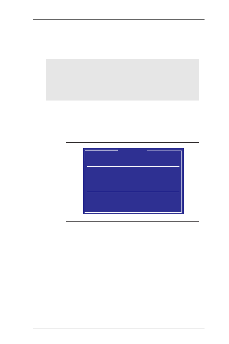
STEP 3: Press <R> key to enter RAID setup utility and start to create array.
SiS RAID BIOS Setting Utility
* Current Created Raid *
[R] : Enter Raid setup utility
[Q] : Exit current menu
Location Model Capacity Mode RAID Type
Disk 1 XXXXXX XXXXXX XXXX XXXXXXX
Disk 2 XXXXXX XXXXXX XXXX XXXXXXX
Copyright (c) 2003-2005. Silicon Integrated Systems Corp | www.sis.com
RAID Setup
6
Page 7
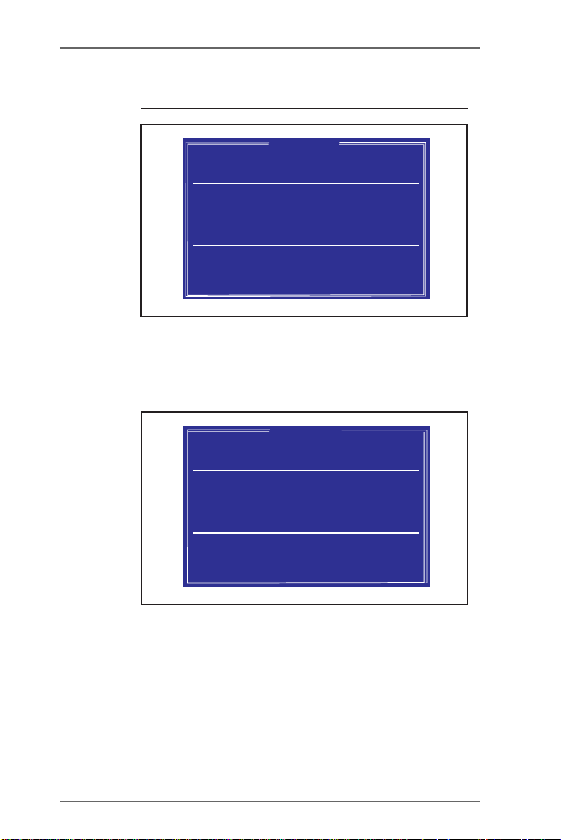
STEP 4: Press <A> key to create array.
SiS RAID BIOS Setting Utility
* Current Created Raid *
Press[A]keytocreateRAID
[Q] : Exit current menu
Location Model Capacity Mode RAID Type
Disk 1 XXXXXX XXXXXX XXXX XXXXXXX
Disk 2 XXXXXX XXXXXX XXXX XXXXXXX
Copyright (c) 2003-2005. Silicon Integrated Systems Corp | www.sis.com
RAID Setup
STEP 5: Press <2> and <Enter> to select RAID 0.
SiS RAID BIOS Setting Utility
* Current Created Raid *
RAID Type: <1> JBOD <2> RAID0 <3> RAID1: 2
[Q] : Exit current menu
Location Model Capacity Mode RAID Type
Disk 1 XXXXXX XXXXXX XXXX XXXXXXX
Disk 2 XXXXXX XXXXXX XXXX XXXXXXX
RAID Setup
Copyright (c) 2003-2005. Silicon Integrated Systems Corp | www.sis.com
7
Page 8
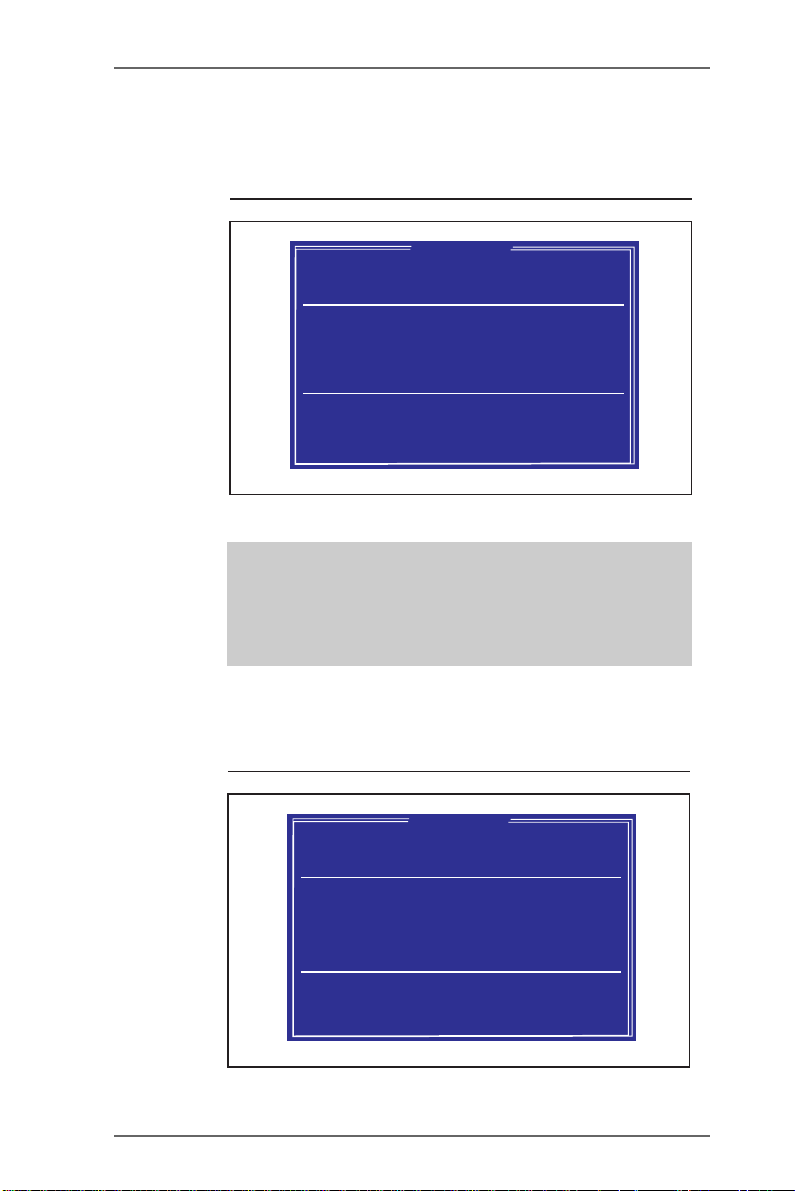
STEP 6: Press <1> or <2> to select Create options. If you select <1> “Auto
Create”, “Disk 1” will be the Source disk. If you select <2> “Manual
Create”, the first selected disk will be the Source disk.
SiS RAID BIOS Setting Utility
* Current Created Raid *
RAID 0
<1> Auto Create<2> Manual Create:2
[Q] : Exit current menu
Location Model Capacity Mode RAID Type
Disk 1 XXXXXX XXXXXX XXXX XXXXXXX
Disk 2 XXXXXX XXXXXX XXXX XXXXXXX
Copyright (c) 2003-2005. Silicon Integrated Systems Corp | www.sis.com
RAID Setup
WARNING!!
The SOURCE disk should be correctly selected,
otherwise, the inside data will be cleared after
RAID 0 created.
STEP 7: If you select <2> “Manual Create” in STEP 6, then the following
screen will appear. Please press <1>-<5> keys and <Enter> to
select Block Size. (Default : 64K)
SiS RAID BIOS Setting Utility
* Current Created Raid *
RAID Setup
RAID 0
Block Size:
<1>16K <2>32K<3>64K <4>128K <5>256K:3
[Q] : Exit current menu
Location Model Capacity Mode RAID Type
Disk 1 XXXXXX XXXXXX XXXX XXXXXXX
Disk 2 XXXXXX XXXXXX XXXX XXXXXXX
Copyright (c) 2003-2005. Silicon Integrated Systems Corp | www.sis.com
8
Page 9

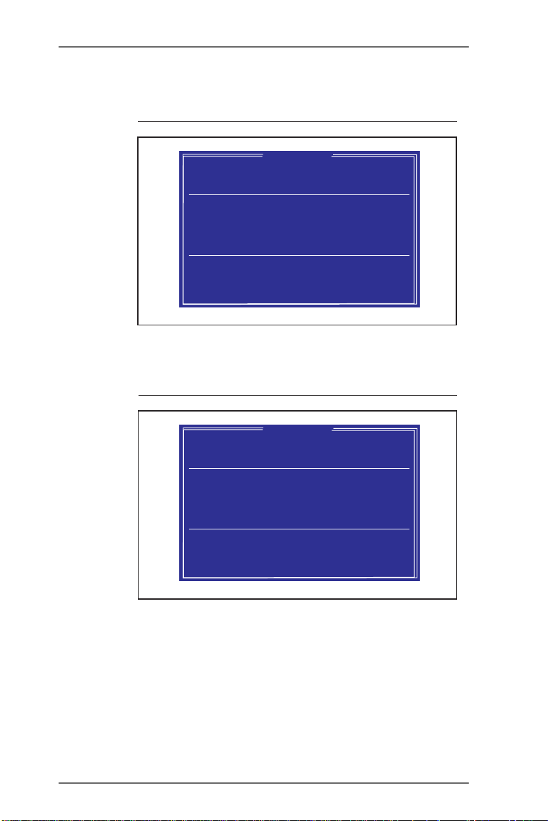
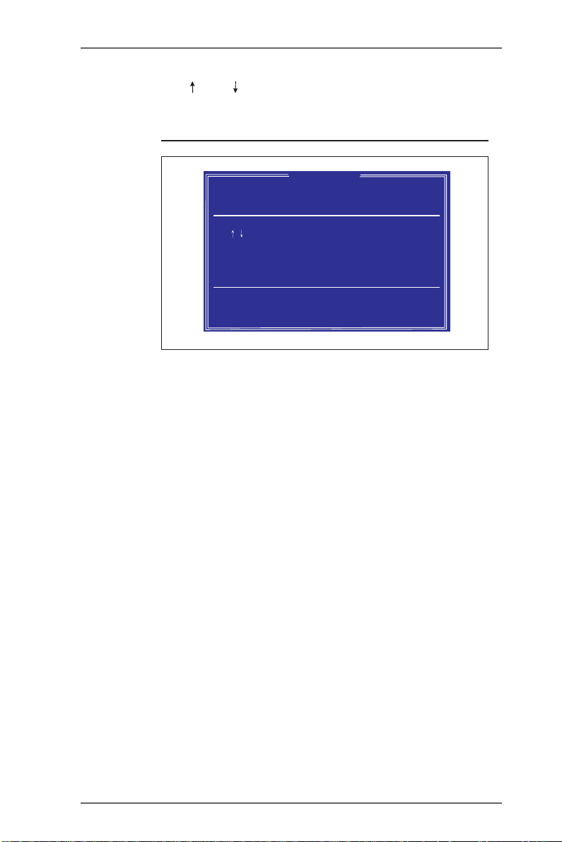
STEP 8: Use < > and < > keys to select disk, and press <Enter> to confirm
your selection. Please note that the disk you select first will be the
SOURCE disk.
SiS RAID BIOS Setting Utility
* Current Created Raid *
RAID 0
Use to selectand press <Enter>to confirm
The disk you select first will be the SOURCE disk
[Q] : Exit current menu
Location Model Capacity Mode RAID Type
Disk 1 XXXXXX XXXXXX XXXX XXXXXXX
Disk 2 XXXXXX XXXXXX XXXX XXXXXXX
Copyright (c) 2003-2005. Silicon Integrated Systems Corp | www.sis.com
RAID Setup
9
Page 10

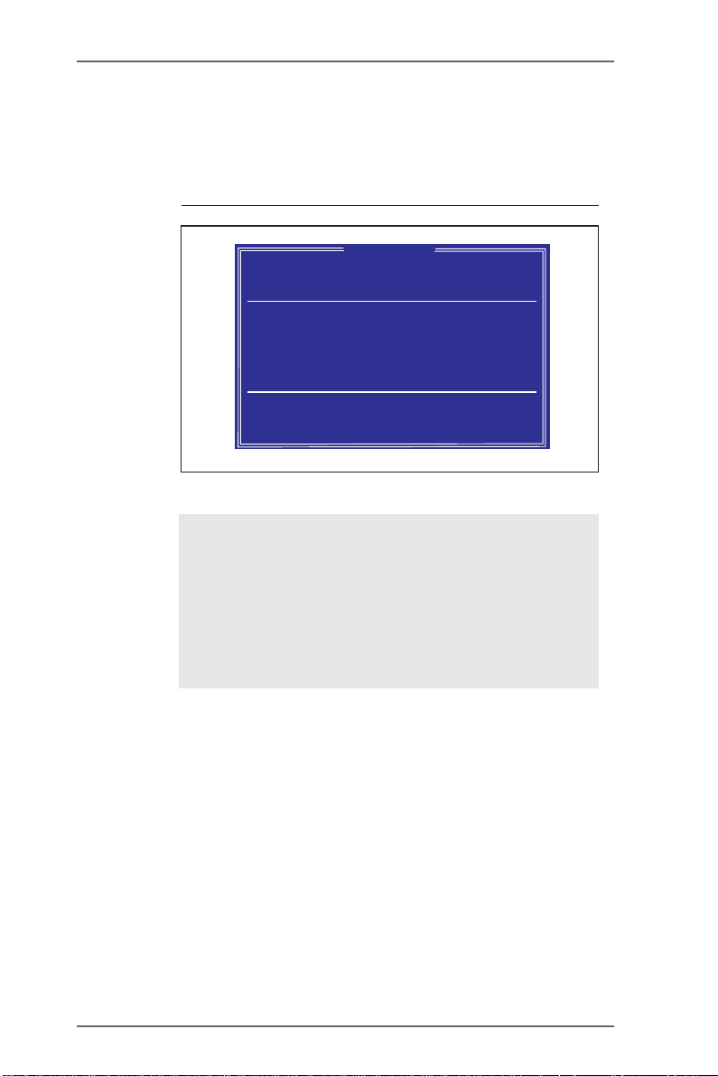
STEP 9: Press <Q> to escape the current setup menu. Then you will see
the following message: “Split the SOURCE (Disk 1) data to RAID
disks? N” If you press <N> and <Enter>, it will Create Stripe only.
If you press <Y> and <Enter>, it will split the data on source disk
to RAID disks.
SiS RAID BIOS Setting Utility
* Current Created Raid *
RAID 0
Split the SOURCE (Disk 1)data to RAID disks ? N
[Q] : Exit current menu
Location Model Capacity Mode RAID Type
Disk 1 XXXXXX XXXXXX XXXX XXXXXXX
Disk 2 XXXXXX XXXXXX XXXX XXXXXXX
Copyright (c) 2003-2005. Silicon Integrated Systems Corp | www.sis.com
RAID Setup
NOTE
If both SATA disks are empty, or you don’t need
the data any more, you should select <N> to save
your time. If you want to keep the data of the
source disk, you should select <Y>. This split action may take several hours depending on the size
of your HDD.
10
Page 11
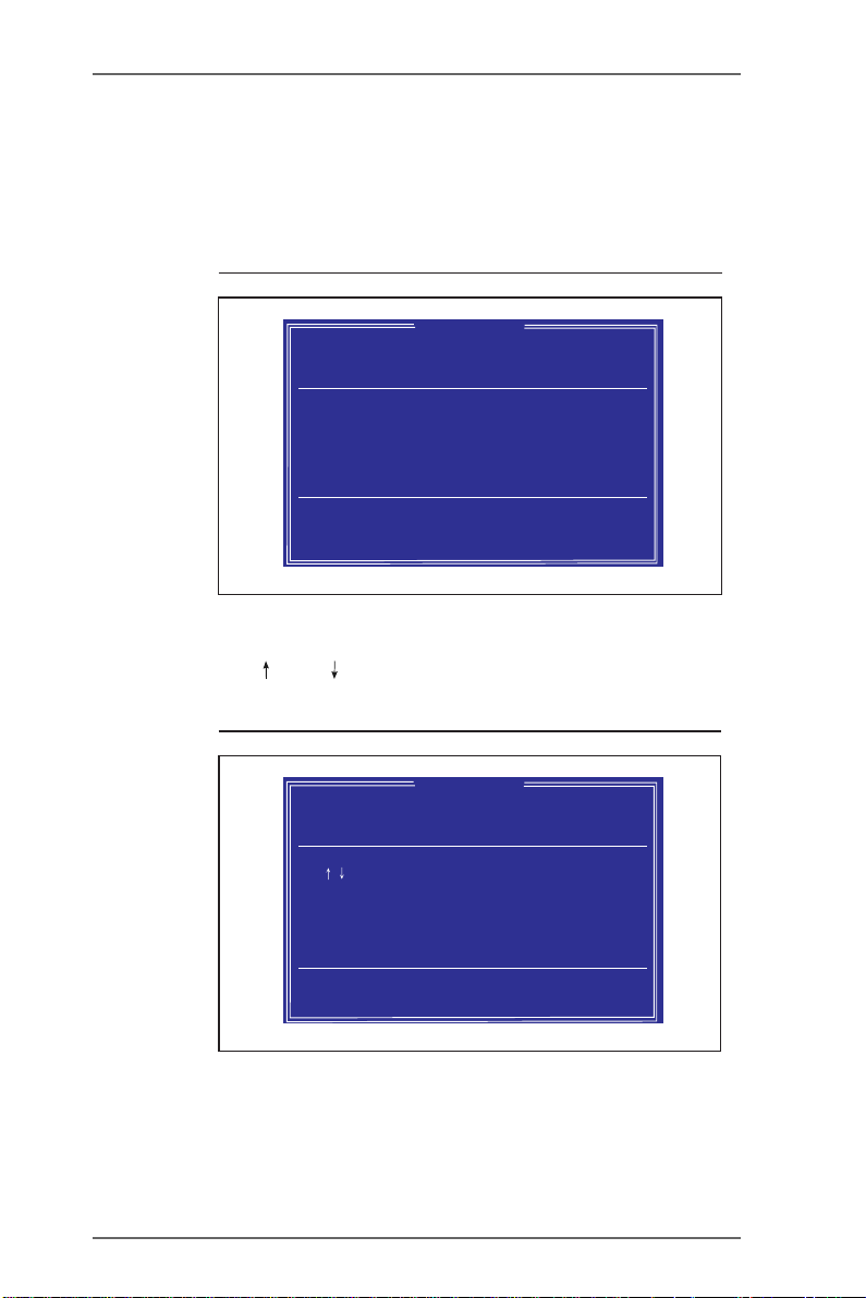
STEP 10: Press <Enter> to escape the current menu. Then the following
screen will appear.
SiS RAID BIOS Setting Utility
* Current Created Raid *
RAID 0: Disk1 Disk 2
Press[D]keytodeleteRAID
[Q] : Exit current menu
Location Model Capacity Mode RAID Type
Disk 1 XXXXXX XXXXXX XXXX XXXXXXX
Disk 2 XXXXXX XXXXXX XXXX XXXXXXX
Copyright (c) 2003-2005. Silicon Integrated Systems Corp | www.sis.com
RAID Setup
STEP 11: Press <Q> again to escape the setup Utility.
SiS RAID BIOS Setting Utility
* Current Created Raid *
RAID 0: Disk1 Disk 2
[R] : Enter Raid setup utility
[Q] : Exit current menu
Location Model Capacity Mode RAID Type
Disk 1 XXXXXX XXXXXX XXXX XXXXXXX
Disk 2 XXXXXX XXXXXX XXXX XXXXXXX
RAID Setup
Copyright (c) 2003-2005. Silicon Integrated Systems Corp | www.sis.com
11
Page 12

STEP 12: Then you will see the confirming message: “Do You Want to Save
Changes? N” Please press <Y> and <Enter> to save changes.
SiS RAID BIOS Setting Utility
* Current Created Raid *
RAID 0: Disk1 Disk 2
[R]:E
[Q]:E
Location Model Capacity Mode RAID Type
Disk 1 XXXXXX XXXXXX XXXX XXXXXXX
Disk 2 XXXXXX XXXXXX XXXX XXXXXXX
Copyright (c) 2003-2005. Silicon Integrated Systems Corp | www.sis.com
Do You Want To Save changes ? N
Pri_Master XXXXXX XXXXXX XXXX XXXXXXX
Sec_Master XXXXXX XXXXXX XXXX XXXXXXX
Disk Status
RAID Setup
STEP 13: Once the array has been created, you will need to FDISK and
format the array as if it were a new single hard drive.
12
Page 13

2.4 RAID 1 Configuration
This section will guide you to configure RAID 1. To set RAID 1 configuration,
please follow the instruction below to use “SiS RAID BIOS Setting Utility” for
the setting of RAID 1 configuration.
NOTE
In the following instruction, the term “Disk 1” refers to the SATA
hard disk that you connect to “SATA1” connector on your
motherboard; the term “Disk 2” refers to the SATA hard disk that
you connect to “SATA2” connector on your motherboard.
STEP 1: Boot-up your computer.
STEP 2: Press <Ctrl-S> key to enter “SiS RAID BIOS Setting Utility”
STEP 3: Press <R> key to enter RAID setup utility and start to create array.
SiS RAID BIOS Setting Utility
* Current Created Raid *
[R] : Enter Raid setup utility
[Q] : Exit current menu
Location Model Capacity Mode RAID Type
Disk 1 XXXXXX XXXXXX XXXX XXXXXXX
Disk 2 XXXXXX XXXXXX XXXX XXXXXXX
Copyright (c) 2003-2005. Silicon Integrated Systems Corp | www.sis.com
RAID Setup
13
Page 14

STEP 4: Press <A> key to create array.
SiS RAID BIOS Setting Utility
* Current Created Raid *
Press[A]keytocreateRAID
[Q] : Exit current menu
Location Model Capacity Mode RAID Type
Disk 1 XXXXXX XXXXXX XXXX XXXXXXX
Disk 2 XXXXXX XXXXXX XXXX XXXXXXX
Copyright (c) 2003-2005. Silicon Integrated Systems Corp | www.sis.com
RAID Setup
STEP 5: Press <3> and <Enter> to select RAID 1.
SiS RAID BIOS Setting Utility
* Current Created Raid *
RAID Type: <1> JBOD <2> RAID0 <3> RAID1: 3
[Q] : Exit current menu
Location Model Capacity Mode RAID Type
Disk 1 XXXXXX XXXXXX XXXX XXXXXXX
Disk 2 XXXXXX XXXXXX XXXX XXXXXXX
RAID Setup
Copyright (c) 2003-2005. Silicon Integrated Systems Corp | www.sis.com
14
Page 15

STEP 6: Press <1> or <2> to select Create options. If you select <1> “Auto
Create”, “Disk 1” will be the SOURCE disk, and the “Disk 2” will be
the MIRROR disk. If you select <2> “Manual Create”, the first selected disk will be the SOURCE disk, and the next selected disk will
be the MIRROR disk.
SiS RAID BIOS Setting Utility
* Current Created Raid *
RAID 1
<1> Auto Create<2> Manual Create:2
[Q] : Exit current menu
Location Model Capacity Mode RAID Type
Disk 1 XXXXXX XXXXXX XXXX XXXXXXX
Disk 2 XXXXXX XXXXXX XXXX XXXXXXX
Copyright (c) 2003-2005. Silicon Integrated Systems Corp | www.sis.com
RAID Setup
WARNING!!
The SOURCE disk should be correctly selected,
otherwise, the inside data will be cleared after
RAID 1 created.
15
Page 16
STEP 7: Use < > and < > keys to select disk, and press <Enter> to confirm
your selection. Please note that the disk you select first will be the
SOURCE disk.
SiS RAID BIOS Setting Utility
* Current Created Raid *
RAID 1
Use to selectand press <Enter>to confirm
The disk you select first will be the SOURCE disk
[Q] : Exit current menu
Location Model Capacity Mode RAID Type
Disk 1 XXXXXX XXXXXX XXXX XXXXXXX
Disk 2 XXXXXX XXXXXX XXXX XXXXXXX
Copyright (c) 2003-2005. Silicon Integrated Systems Corp | www.sis.com
RAID Setup
16
Page 17
STEP 8: Then you will see the following message: “Duplicate the SOURCE
(Disk 1) data to RAID disks ? N”. If you press <N> a nd <Enter>, it will
Create Mirror only. If you press <Y> and <Enter>, it will duplicate
the data on source disk to RAID disks.
SiS RAID BIOS Setting Utility
* Current Created Raid *
RAID 1
Duplicate the SOURCE (Disk 1)data to RAID disks ? N
[Q] : Exit current menu
Location Model Capacity Mode RAID Type
Disk 1 XXXXXX XXXXXX XXXX XXXXXXX
Disk 2 XXXXXX XXXXXX XXXX XXXXXXX
Copyright (c) 2003-2005. Silicon Integrated Systems Corp | www.sis.com
RAID Setup
NOTE
If both SATA disks are empty, or you don’t need
the data any more, you should select <N> to save
your time. If you want to keep the data of the
SOURCE disk, you should select <Y>. This mirror
action may take several hours depending on the
size of your HDD.
17
Page 18

STEP 9: Press <Q> to escape the setup menu.
SiS RAID BIOS Setting Utility
* Current Created Raid *
RAID 1: Disk1 Disk 2
[R] : Enter Raid setup utility
[Q] : Exit current menu
Location Model Capacity Mode RAID Type
Disk 1 XXXXXX XXXXXX XXXX XXXXXXX
Disk 2 XXXXXX XXXXXX XXXX XXXXXXX
Copyright (c) 2003-2005. Silicon Integrated Systems Corp | www.sis.com
STEP 10: Bef o re y o u es c ape the setup Utility, you will see the confirming
message: “Do You Want to Save Changes? N” Please press <Y>
and <Enter> to save changes.
RAID Setup
SiS RAID BIOS Setting Utility
* Current Created Raid *
RAID 1: Disk1 Disk 2
[R]:E
[Q]:E
Location Model Capacity Mode RAID Type
Disk 1 XXXXXX XXXXXX XXXX XXXXXXX
Disk 2 XXXXXX XXXXXX XXXX XXXXXXX
Do You Want To Save changes ? N
Pri_Master XXXXXX XXXXXX XXXX XXXXXXX
Sec_Master XXXXXX XXXXXX XXXX XXXXXXX
Disk Status
RAID Setup
Copyright (c) 2003-2005. Silicon Integrated Systems Corp | www.sis.com
STEP 1 1: Once the array has been created, you will need to FDISK and
format the array as if it were a new single hard drive.
18
Page 19

2.5 JBOD Configuration
This section will guide you to configure JBOD. To set JBOD configuration,
please follow the instruction below to use “SiS RAID BIOS Setting Utility” for
the setting of JBOD configuration.
NOTE
In the following instruction, the term “Disk 1” refers to the SATA
hard disk that you connect to “SATA1” connector on your
motherboard; the term “Disk 2” refers to the SATA hard disk that
you connect to “SATA2” connector on your motherboard.
STEP 1: Boot-up your computer.
STEP 2: Press <Ctrl-S> key to enter “SiS RAID BIOS Setting Utility”
STEP 3: Press <R> key to enter RAID setup utility and start to create array.
SiS RAID BIOS Setting Utility
* Current Created Raid *
[R] : Enter Raid setup utility
[Q] : Exit current menu
Location Model Capacity Mode RAID Type
Disk 1 XXXXXX XXXXXX XXXX XXXXXXX
Disk 2 XXXXXX XXXXXX XXXX XXXXXXX
Copyright (c) 2003-2005. Silicon Integrated Systems Corp | www.sis.com
RAID Setup
19
Page 20

STEP 4: Press <A> key to create array.
SiS RAID BIOS Setting Utility
* Current Created Raid *
Press[A]keytocreateRAID
[Q] : Exit current menu
Location Model Capacity Mode RAID Type
Disk 1 XXXXXX XXXXXX XXXX XXXXXXX
Disk 2 XXXXXX XXXXXX XXXX XXXXXXX
RAID Setup
Copyright (c) 2003-2005. Silicon Integrated Systems Corp | www.sis.com
STEP 5: Press <1> and <Enter> to select JBOD.
SiS RAID BIOS Setting Utility
Disk Status
* Current Created Raid *
[B] : Select Boot Disk
RAID Type: <1> JBOD <2> RAID0 <3> RAID1: 1
[R] : Enter Raid setup utility
[Q] : Exit the menu
[Q] : Exit current menu
Location Model Capacity Mode RAID Type
Location Model Capacity Mode RAID Type
Pri_Master XXXXXX XXXXXX XXXX XXXXXXX
Pri_Master XXXXXX XXXXXX XXXX XXXXXXX
Disk 1 XXXXXX XXXXXX XXXX XXXXXXX
Sec_Master XXXXXX XXXXXX XXXX XXXXXXX
Sec_Master XXXXXX XXXXXX XXXX XXXXXXX
Disk 2 XXXXXX XXXXXX XXXX XXXXXXX
The selectedboot disk ismarked by "*"
RAID Setup
Copyright (c) 2003-2005. Silicon Integrated Systems Corp | www.sis.com
20
Page 21
STEP 6: Press <1> or <2> to select Create options. If you select <1> “Auto
Create, the “Disk 1” will be the first disk, and “Disk 2” will be the
second disk. If you select <2> “Manual Create”, the first selected
disk will be the first disk, and the next selected disk will be the
second disk.
SiS RAID BIOS Setting Utility
* Current Created Raid *
JBOD
<1> Auto Create<2> Manual Create:2
[Q] : Exit current menu
Location Model Capacity Mode RAID Type
Disk 1 XXXXXX XXXXXX XXXX XXXXXXX
Disk 2 XXXXXX XXXXXX XXXX XXXXXXX
Copyright (c) 2003-2005. Silicon Integrated Systems Corp | www.sis.com
RAID Setup
STEP 7: Use < > and < > keys to select disk, and press <Enter> to select
disk.
SiS RAID BIOS Setting Utility
* Current Created Raid *
RAID 0
Block Size:
[Q] : Exit the menu
JBOD
Use to selectand press <Enter>to confirm
The disk you select first will be the SOURCE disk
[Q] : Exit current menu
Location Model Capacity Mode RAID Type
Disk 1 XXXXXX XXXXXX XXXX XXXXXXX
Disk 2 XXXXXX XXXXXX XXXX XXXXXXX
<1>16K <2>32K<3>64K <4>128K <5>256K:3
Location Model Capacity Mode RAID Type
Pri_Master XXXXXX XXXXXX XXXX XXXXXXX
Pri_Master XXXXXX XXXXXX XXXX XXXXXXX
Sec_Master XXXXXX XXXXXX XXXX XXXXXXX
Sec_Master XXXXXX XXXXXX XXXX XXXXXXX
Disk Status
RAID Setup
Copyright (c) 2003-2005. Silicon Integrated Systems Corp | www.sis.com
21
Page 22

STEP 8: Press <Q> to escape the setup menu.
SiS RAID BIOS Setting Utility
Disk Status
* Current Created Raid *
JBOD: Disk1 Disk 2
RAID 0
[R] : Enter Raid setup utility
DoyouwanttoSplittheSOURCEdiskdatatootherdisks?N
[Q] : Exit the menu
[Q] : Exit current menu
Location Model Capacity Mode RAID Type
Location Model Capacity Mode RAID Type
Pri_Master XXXXXX XXXXXX XXXX XXXXXXX
Pri_Master XXXXXX XXXXXX XXXX XXXXXXX
Disk 1 XXXXXX XXXXXX XXXX XXXXXXX
Sec_Master XXXXXX XXXXXX XXXX XXXXXXX
Sec_Master XXXXXX XXXXXX XXXX XXXXXXX
Disk 2 XXXXXX XXXXXX XXXX XXXXXXX
The selectedboot disk ismarked by "*"
Copyright (c) 2003-2005. Silicon Integrated Systems Corp | www.sis.com
RAID Setup
STEP 9: Then you will see the confirming message: “Do You Want to Save
Changes? N” Please press <Y> and <Enter> to save changes.
SiS RAID BIOS Setting Utility
Disk Status
RAID Setup
* Current Created Raid *
JBOD: Disk1 Disk 2
[R]:E
[Q]:E
Location Model Capacity Mode RAID Type
Disk 1 XXXXXX XXXXXX XXXX XXXXXXX
Disk 2 XXXXXX XXXXXX XXXX XXXXXXX
Copyright (c) 2003-2005. Silicon Integrated Systems Corp | www.sis.com
Do You Want To Save changes ? N
Pri_Master XXXXXX XXXXXX XXXX XXXXXXX
Sec_Master XXXXXX XXXXXX XXXX XXXXXXX
WARNING!!
After the JBOD function is created, the original
data in both SATA disks will be cleared.
STEP 10: Once the array has been created, you will need to FDISK and
format the array as if it were a new single hard drive.
22
Page 23

3. Installation of Windows 2000 / Windows XP
If you want to install Windows 2000 or Windows XP on your SATA HDDs,
you will need to make an SATA driver diskette (see page 3 for details)
before you start the OS installation. If you prefer not to use RAID function,
you may start to install Windows 2000 / Windows XP once you have the
SATA driver diskette ready. If you want to use RAID function, you need to
set the RAID configuration (see page 4 to page 22) before you install Windows 2000 / Windows XP.
For the installation of the SATA drivers while installing Windows 2000 or
Windows XP, please follow the instruction below.
1. Insert Windows 2000 or Windows XP CD into the optical drive.
2. Remove the floppy diskette, and reboot the system. When you start the
installation, press <F6> once you see the message at the bottom of the
screen, “Press F6 if you need to install a third party SCSI or RAID driver”.
Press F6 if you need to install a third party SCSI or RAID driver...Press F6 if you need to install a third party SCSI or RAID driver...
23
Page 24

Press F6 if you need to install a third party SCSI or RAID driver...S=Specify Additional Device ENTER=Continue F3=Exit
Windows Setup
Setup could not determine the type of one or more mass storage devices
installed in your system, or you have chosen to manually specify an adapter.
Currently, Setup will load support for the following mass atorage devices.
<none>
To specify additional SCSI adapters, CD-ROM drives, or special
disk controllers for use with Windows, including those for
which you have a device support disk from a mass storage device
manufacturer, press S.
If you do not have any device support disks from a mass storage
device manufacturer, or do not want to specify additional
mass storage devices for use with Windows, press ENTER.
Press F6 if you need to install a third party SCSI or RAID driver...ENTER=Continue ESC=Cancel F3=Exit
Windows Setup
Please insert the disk labeled
Manufacturer-supplied hardware support disk
into Drive A:
Press ENTER when ready.
3. When the Windows 2000 / Windows XP Setup window is generated,
press <S> key to specify an Additional Device(s).
4. Insert the SATA driver into drive A: and press <Enter>.
24
Page 25

5. Choose one of the following items:
“WinXP SiS Raid/IDE Controller” (for RAID),
“Win2000 SiS Raid/IDE Controller” (for RAID),
that appears on screen, and then press <Enter> key.
Windows Setup
You have chosen to configure a SCSI Adapter for use with Windows,
using a device support disk provided by an adapter manufacturer.
Select the SCSI Adapter you want from the following list, or press ESC
to return to the previous screen.
WinXP SiS Raid / IDE Controller
Win2000 SiS Raid /IDE Controller
Press F6 if you need to install a third party SCSI or RAID driver...ENTER=Continue ESC=Cancel F3=Exit
6. Press <Enter> to continue with installation or if you need to specify any
additional devices to be installed, do so at this time. Once all devices are
specified, Press Enter to continue with installation.
7. From the Windows 2000/Windows XP Setup screen, press <Enter>
key. Setup will now load all device files and then continue the Windows
2000 / Windows XP installation.
8. Ple ase install the driver package again while the operation system has
been setup.
NOTE
If you would like to install windows to any RAID set, you
should create RAID from BIOS utility first and then follow the
steps above.
25
 Loading...