

Page 1
Page 2

Version 1.0
Published November 2019
Copyright©2019 ASRock INC. All rights reser ved.
Copyright Notice:
No part of this documentation may be reproduced, transcribed, transmitted, or
translated in any language, in any form or by any means, except duplication of
documentation by the purchaser for backup purpose, without written consent of
ASRock Inc.
Products and corporate names appearing in this documentation may or may not
be registered trademarks or copyrights of their respective companies, and are used
only for identication or explanation and to the owners’ benet, without intent to
infringe.
Disclaimer:
Specications and information contained in this documentation are furnished for
informational use only and subject to change without notice, and should not be
constructed as a commitment by ASRock. ASRock assumes no responsibility for
any errors or omissions that may appear in this documentation.
With respect to the contents of this documentation, ASRock does not provide
warranty of any kind, either expressed or implied, including but not limited to
the implied warranties or conditions of merchantability or tness for a particular
purpose.
In no event shall ASRock, its directors, ocers, employees, or agents be liable for
any indirect, special, incidental, or consequential damages (including damages for
loss of prots, loss of business, loss of data, interruption of business and the like),
even if ASRock has been advised of the possibility of such damages arising from any
defect or error in the documentation or product.
is device complies with Part 15 of the FCC Rules. Operation is subject to the following
two conditions:
(1) this device may not cause harmful interference, and
(2) this device must accept any interference received, including interference that
may cause undesired operation.
CALIFORNIA, USA ONLY
e Lithium battery adopted on this motherboard contains Perchlorate, a toxic substance
controlled in Perchlorate Best Management Practices (BMP) regulations passed by the
California Legislature. When you discard the Lithium battery in California, USA, please
follow the related regulations in advance.
“Perchlorate Material-special handling may apply, see ww w.dtsc.ca.gov/hazardouswaste/
perchlorate”
ASRock Website: http://www.asrock.com
Page 3

AUSTRALIA ONLY
Our goods come with guarantees that cannot be excluded under the Australian Consumer
Law. You are entitled to a replacement or refund for a major failure and compensation for
any other reasonably foreseeable loss or damage caused by our goods. You are also entitled
to have the goods repaired or replaced if the goods fail to be of acceptable quality and the
failure does not amount to a major failure. If you require assistance please call ASRock Tel
: +886-2-28965588 ext.123 (Standard International call charges apply)
e terms HDMI® and HDMI High-Denition Multimedia Interface, and the
HDMI logo are trademarks or registered trademarks of HDMI Licensing LLC in the
United States and other countries.
Page 4

Contents
Chapter 1 Introduction 1
1.1 Package Contents 1
1.2 Specications 2
1.3 Motherboard Layout 4
1.4 I/O Panel 6
Chapter 2 Installation 7
2.1 Installing the System Fan 8
2.2 Installing Memory Modules (DIMM) 9
2.3 Expansion Slots (PCI Express Slots) 11
2.4 Jumpers Setup 12
2.5 Onboard Headers and Connectors 13
Chapter 3 Software and Utilities Operation 16
3.1 Installing Drivers 16
3.2 ASRock Live Update & APP Shop 17
3.2.1 UI Overview 17
3.2.2 Apps 18
3.2.3 BIOS & Drivers 21
3.2.4 Setting 22
Page 5

Page 6

QC7000M / QC6000M
Chapter 1 Introduction
ank you for purchasing ASRock QC7000M / QC6000M motherboard, a reliable
motherboard produced under ASRock’s consistently stringent quality control.
It delivers excellent performance with robust design conforming to ASRock’s
commitment to quality and endurance.
In this manual, Chapter 1 and 2 contains the introduction of the motherboard
and step-by-step installation guides. Chapter 3 contains the operation guide of the
soware and utilities. Chapter 4 contains the conguration guide of the BIOS setup.
Becau se the motherboard specications and the BIOS soware might be updated, the
content of this manual will be subject to change without notice. In ca se any modications of this manual occur, the updated version will be available on ASRock’s website
without further notice. If you require technical suppor t related to this motherboard,
please visit our website for spe cic information about the model you are using. You
may nd the l atest VGA cards and CPU suppor t list on ASRock’s website a s well.
ASRock website http://www.asrock.com.
1.1 Package Contents
ASRock QC7000M / QC6000M Motherboard (Micro ATX Form Factor)
•
ASRock QC7000M / QC6000M Quick Installation Guide
•
ASRock QC7000M / QC6000M Support CD
•
2 x Serial ATA (SATA) Data Cables (Optional)
•
1 x I/O Panel Shield
•
English
1
Page 7

1.2 Specications
Platform
CPU
Chipset
Memory
Expansion
Slot
Graphics
•
•
•
•
•
•
•
•
•
* Please refer to Memory Support List on ASRock's website for
more information. (http://www.asrock.com/)
•
•
•
•
•
•
•
•
•
Micro ATX Form Factor
Solid Capacitor design
High Density Glass Fabric PCB
AMD FT3b Carrizo-L E2-7110 Quad-Core APU
(for QC7000M)
AMD FT3b Beema E2-6110 Quad-Core APU (for QC6000M)
SOC
2 x DDR3 DIMM Slots
Supports DDR3 1600/1333 non-ECC, un-buered memory
Max. capacity of system memory: 32GB
1 x PCI Express 2.0 x16 Slot (PCIE2: x4 mode)
2 x PCI Express 2.0 x1 Slot
Integrated AMD Radeon™ R2 Graphics
DirectX 12, Pixel Shader 5.0 (for QC7000M)
DirectX 11.1, Pixel Shader 5.0 (for QC6000M)
Dual graphics output: support D-Sub and HDMI ports by
independent display controllers
Supports HDMI 1.4 with max. resolution up to
3200x1800@60 Hz or 4096x2160@24 Hz
Supports D-Sub with max. resolution up to 1920x1200@60Hz
Supports HDCP 1.4 with HDMI 1.4 Port
English
2
Audio
LAN
7.1 CH HD Audio (Realtek ALC887 Audio Codec)
•
Supports Surge Protection
•
ELNA Audio Caps
•
PCIE x1 Gigabit LAN 10/100/1000 Mb/s
•
Realtek RTL8111H
•
Supports Wake-On-LAN
•
Supports Lightning/ESD Protection
•
Supports Energy Ecient Ethernet 802.3az
•
Supports PXE
•
Page 8

Rear Panel
I/O
Storage
Connector
QC7000M / QC6000M
1 x PS/2 Mouse/Keyboard Port
•
1 x Serial Port: COM1
•
1 x D-Sub Port
•
1 x HDMI Port
•
4 x USB 2.0 Ports (Supports ESD Protection)
•
2 x USB 3.2 Gen1 Ports (Supports ESD Protection)
•
1 x RJ-45 LAN Port with LED (ACT/LINK LED and SPEED
•
LED)
HD Audio Jacks: Line in / Front Speaker / Microphone
•
2 x SATA3 6.0 Gb/s Connectors, support NCQ, AHCI and
•
Hot Plug
1 x CPU Fan Connector (3-pin)
•
2 x Chassis Fan Connectors (1 x 4-pin, 1 x 3-pin)
•
1 x 24 pin ATX Power Connector
•
1 x Front Panel Audio Connector
•
2 x USB 2.0 Headers (Support 4 USB 2.0 ports) (Supports ESD
•
Protection)
AMI UEFI Legal BIOS with multilingual GUI support
BIOS
Feature
Hardware
Monitor
OS
Certications
* For detailed product information, please visit our website: http://www.asrock.com
•
Supports “Plug and Play”
•
ACPI 1.1 compliance wake up events
•
SMBIOS 2.3.1 support
•
DRAM Voltage multi-adjustment
•
CPU/Chassis temperature sensing
•
CPU/Chassis Fan Tachometer
•
CPU/Chassis Quiet Fan
•
CPU/Chassis Fan multi-speed control
•
Voltage monitoring: +12V, +5V, +3.3V, Vcore
•
Microso® Windows® 10 64-bit
•
FCC, CE
•
ErP/EuP ready (ErP/EuP ready power supply is required)
•
English
3
Page 9
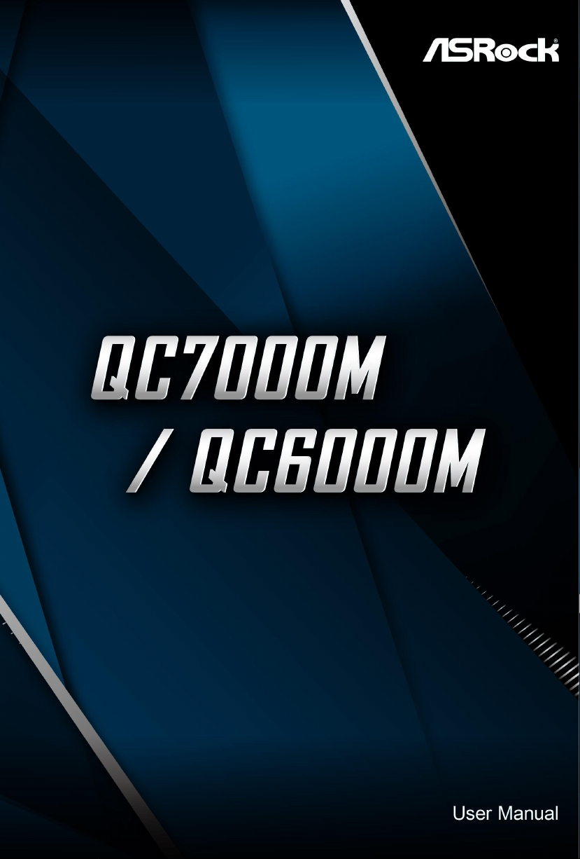
1.3 Motherboard Layout
ATXPWR1
FS B80 0
DDR 3_A1 (6 4 bit, 24 0-pin m odule )
DDR 3_A2 (6 4 bit, 24 0-pin m odule )
LAN
1
CLRCMOS1
PCIE2
1
USB6_7
1
USB4_5
HD_AUDIO1
1
CHA_FAN1
SPEAKER1
1
HDLED RESET
PLED PWRBTN
1
PANEL1
RJ- 45 LAN
USB 2.0
T: USB2
B: USB3
CPU_FAN1
21
3
4
7
USB 2.0
T: USB0
B: USB1
PS2
Keyboard/
Mouse
HDMI1
Top:
LINE IN
Cente r:
FRONT
Botto m:
MIC IN
8
CHA_FAN2
USB 3.2 Gen1
T: USB0
B: USB1
AUDIO
CODEC
COM1
VGA1
CMOS
Battery
PCIE3
PCIE1
12
11
10 9
13
SATA3_1
SATA3_2
5
6
English
4
RoHS
BIOS
Page 10

No. Description
1 CPU Fan Connector (CPU_FAN1)
2 2 x 240-pin DDR3 DIMM Slots (DDR3_A1, DDR3_A2)
3 Chassis Fan Connector (CHA_FAN1)
4 ATX Power Connector (ATXPWR1)
5 SATA3 Connector (SATA3_1)
6 SATA3 Connector (SATA3_2)
7 USB 2.0 Header (USB4_5)
8 Chassis Fan Connector (CHA_FAN2)
9 System Panel Header (PANEL1)
10 Chassis Speaker Header (SPEAKER1)
11 Clear CMOS Jumper (CLRCMOS1)
12 USB 2.0 Header (USB6_7)
13 Front Panel Audio Header (HD_AUDIO1)
QC7000M / QC6000M
English
5
Page 11
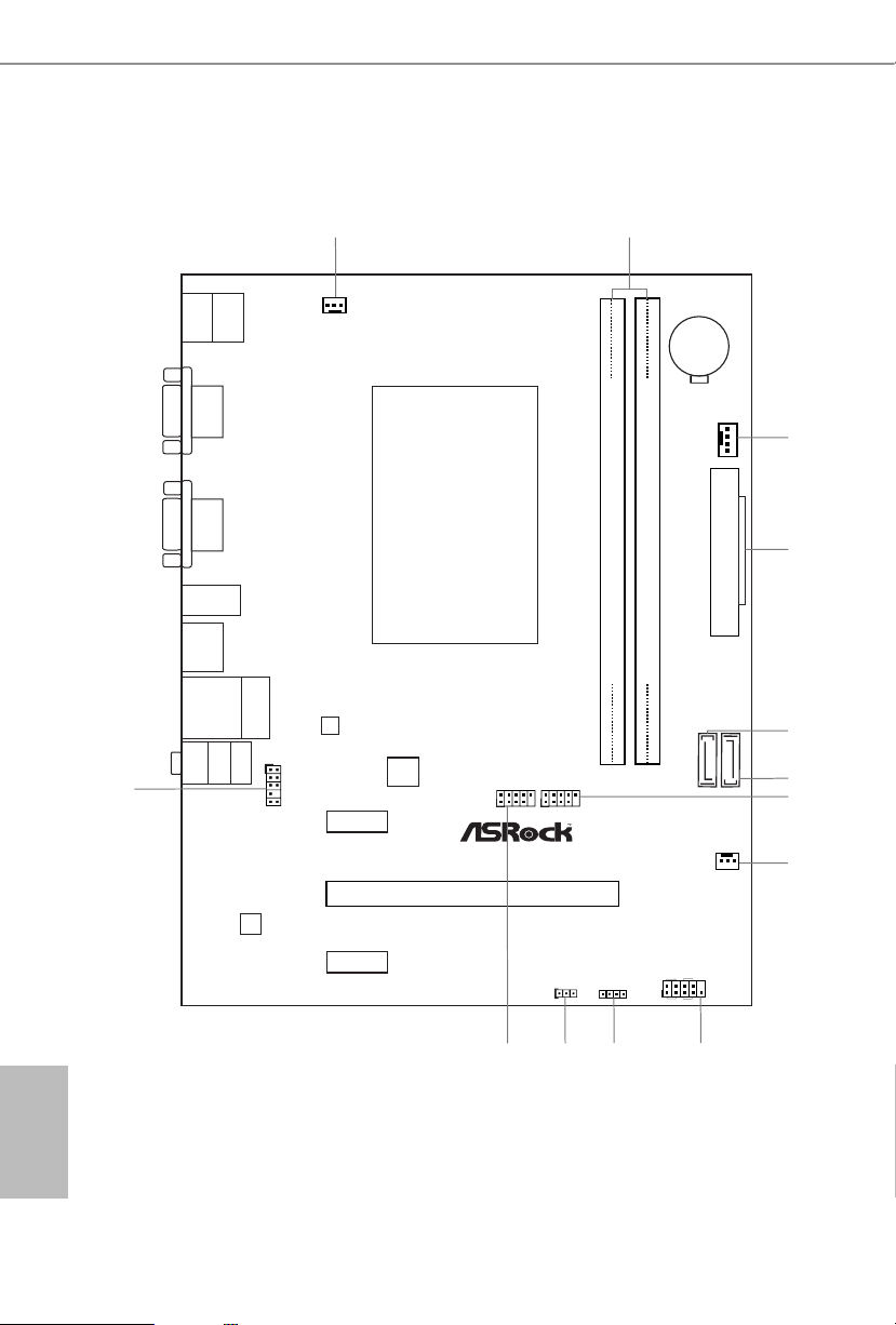
1.4 I/O Panel
1 2
3
4
English
6711 8910
No. Description No. Description
1 USB 2.0 Ports (USB01) 7 USB 3.2 Gen1 Ports (USB3_0_1)
2 LAN RJ-45 Port* 8 HDMI Port
3 Line In (Light Blue) 9 D-Sub Port
4 Front Speaker (Lime) 10 COM Port
5 Microphone (Pink) 11 PS/2 Mouse/Keyboard Port
6 USB 2.0 Ports (USB_2_3)
* ere are two LEDs on each LAN port. Please refer to the table below for the LAN port LED indications.
ACT/LINK LED
SPEED LED
LAN Por t
Activity / Link LED Speed LED
Status Description Status Description
O No Link O 10Mbps connection
Blinking Data Activity Orange 100Mbps connection
On Link Green 1Gbps connection
5
6
Page 12

QC7000M / QC6000M
Chapter 2 Installation
is is a Micro ATX form factor motherboard. Before you install the motherboard,
study the conguration of your chassis to ensure that the motherboard ts into it.
Pre-installation Precautions
Take note of the following precautions before you install motherboard components
or change any motherboard settings.
Make sure to unplug the power cord before installing or removing the motherboard.
•
Failure to do so may cause physical injuries to you and damages to motherboard
components.
In order to avoid damage from static electricity to the motherboard’s components,
•
NEVER place your motherboard directly on a carpet. Also remember to use a grounded
wrist strap or touch a safety grounded object before you handle the components.
Hold components by the edges and do not touch the ICs.
•
Whenever you uninstall any components, place them on a grounded anti-static pad or
•
in the bag that comes with the components.
When placing screws to secure the motherboard to the chassis, please do not over-
•
tighten the screws! Doing so may damage the motherboard.
English
7
Page 13

2.1 Installing the System Fan
Please install the motherboard into a case with good airow. Although the CPU
is covered by a pre-installed heatsink which allows advanced heat dissipation,
it is highly recommended to use system fan(s) to increase the cooling eciency.
English
8
Page 14

QC7000M / QC6000M
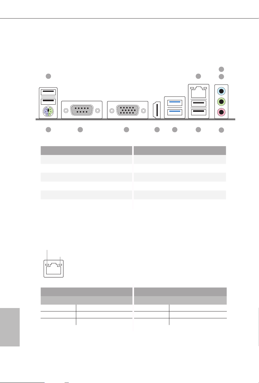
2.2 Installing Memory Modules (DIMM)
is motherboard provides two 240-pin DDR3 (Double Data Rate 3) DIMM slots.
It is not allowed to install a DDR or DDR2 memory module into a DDR3 slot; otherwise, this motherboard and DIMM may be dam aged.
e DIMM only ts in one correct orie ntation. It will cause permanent dam age to
the motherboard and the DIMM if you force the DIMM into the slot at incor rect
orientation.
English
9
Page 15
1
2
English
10
3
Page 16

QC7000M / QC6000M
2.3 Expansion Slots (PCI Express Slots)
ere are 3 PCI Express slots on the motherboard.
Before installing an ex pansion card, please make sure that the power supply is
switched o or the power cord is unplugged. Plea se read the documentation of the
expan sion card and mak e necessary h ardware settings for the card before you start
the installation.
PCIe slots:
PCIE1 (PCIe 2.0 x1 slot) is used for PCI Express x1 lane width cards.
PCIE2 (PCIe 2.0 x16 slot) is used for PCI Express x4 lane width graphics cards.
PCIE3 (PCIe 2.0 x1 slot) is used for PCI Express x1 lane width cards.
11
English
Page 17

2.4 Jumpers Setup
e illustration shows how jumpers are setup. When the jumper cap is placed on
the pins, the jumper is “Short”. If no jumper cap is placed on the pins, the jumper
is “Open”. e illustration shows a 3-pin jumper whose pin1 and pin2 are “Short”
when a jumper cap is placed on these 2 pins.
Clear CMOS Jumper
(CLRCMO S1)
(see p.4, No. 11)
CLRCMOS1 allows you to clear the data in CMOS. To clear and reset the system
parameters to default setup, please turn o the computer and unplug the power
cord from the power supply. Aer waiting for 15 seconds, use a jumper cap to
short pin2 and pin3 on CLRCMOS1 for 5 seconds. However, please do not clear
the CMOS right aer you update the BIOS. If you need to clear the CMOS when
you just nish updating the BIOS, you must boot up the system rst, and then shut
it down before you do the clear-CMOS action. Please be noted that the password,
date, time, and user default prole will be cleared only if the CMOS battery is
removed.
Clear CMOSDefault
English
12
Page 18

2.5 Onboard Headers and Connectors
PLED+
1
Onboard headers and connectors are NOT jump ers. Do NOT place jumper caps over
these headers and connectors. Placing jumper caps over the headers and connectors
will cause permanent damage to the motherboard.
QC7000M / QC6000M
System Panel Header
(9-pi n PANEL1)
(see p.4, No. 9)
PWRBTN (Power Switch):
Connec t to the power switch on the ch assi s front panel. You may congure the way to
turn o your system using the power switch.
RESET (Reset Switch):
Connec t to the reset switch on the chassi s front panel. Press the reset sw itch to restart
the computer if the compute r freezes and fails to perform a norm al restart.
PLED (Syste m Power LED):
Connec t to the power status indicator on the chas sis front panel. e LED i s on when
the system is ope rating. e LED keeps blinking when the system i s in S3 sleep state.
e LED is o when the system i s in S4 sle ep state or powered o (S5).
HDLED (Ha rd Drive Activity LED):
Connec t to the hard drive ac tivity LED on the chassis front panel. e LED is on when
the hard dr ive is reading or w riting data.
e front panel de sign may dier by chassis. A front panel module mainly consists
of power s witch , reset switch, power LED, hard dr ive activity LED, speak er and etc.
When connect ing your chassis front panel module to this head er, make sure the wire
assig nments and the pin assig nments are matched correctly.
PLED-
HDLED-
HDLED+
PWRBTN#
GND
RESET#
GND
GND
Connect the power
switch, reset switch and
system status indicator on
the chassis to this header
according to the pin
assignments below. Note
the positive and negative
pins before connecting
the cables.
English
13
Page 19

Serial ATA3 Connectors
DUMMY
GND
GND
P+
P-
USB_PWR
P+
P-
USB_PWR
1
J_SENS
E
OUT2_L
1
MIC_RET
PRESENCE#
GND
OUT2_R
MIC2_R
MIC2_L
OUT_RET
(SATA3_1:
see p.4, No. 5)
(SATA3_ 2:
see p.4, No. 6)
SATA3_1
ese two SATA3
connectors support SATA
SATA3_2
data cables for internal
storage devices with up to
6.0 Gb/s data transfer rate.
USB 2.0 Headers
(9-pin USB4_5)
(see p.4, No. 7)
(9-pin USB6_7)
(see p.4, No. 12)
Front Panel Audio Header
(9-pin HD_ AUDIO1)
(see p.4, No. 13)
1. High Denition Audio support s Jack Sensing, but the panel wire on the cha ssis must
suppor t HDA to function correc tly. Please follo w the instructions in our manual and
chassis manual to install your system.
2. If you use an AC’97 audio panel , please install it to th e front panel audio header by
the steps below:
A. Connect Mic_IN (MIC) to MIC2_ L.
B. Conne ct Audio_R (RIN) to OUT2_R and Audio_ L (LIN) to OUT2_ L.
C. Connect Ground (GND) to Ground (GND).
D. MIC_ RET and OUT_RET are for the HD audio panel only. You don’t ne ed to
connec t them for the AC’97 audio panel.
E. To activate the front mic, go to the “FrontMic” Tab in the Realtek Control panel
and adjust “Recording Volume”.
ere are two headers
on this motherboard.
Each USB 2.0 header can
support two ports.
is header is for
connecting audio devices
to the front audio panel.
English
14
Page 20

QC7000M / QC6000M
1
DUMMY
SPEAKER
GND
OL
CHA_FAN_SPEED
GN
N_SPEED
Chassis Speaker Header
(4-p i n SPEAKER1)
(see p.4, No. 10)
Chassis Fan Connectors
(4-pin CHA_FAN1)
(see p.4, No. 3)
(3-pi n CHA_FAN2)
(see p.4, No. 8)
CPU Fan Connector
(3-pin CPU_FAN1)
(see p.4, No. 1)
ATX Power Connector
(24-p i n ATX PWR1)
(see p.4, No. 4)
+5V
+12V
CHA_FAN_SPEED
FAN_SPEED_CONTR
GND
FAN_VOLTAGE
D
FAN_VOLTAGE
CPU_FA
12
1
DUMMY
24
13
Please connect the chassis
speaker to this header.
Please connect fan cables
to the fan connectors and
match the black wire to
the ground pin.
Please connect fan cables
to the fan connectors and
match the black wire to
the ground pin.
is motherboard pro-
vides a 24-pin ATX power
connector. To use a 20-pin
ATX power supply, please
plug it along Pin 1 and Pin
13.
English
15
Page 21

Chapter 3 Software and Utilities Operation
3.1 Installing Drivers
e Support CD that comes with the motherboard contains necessary drivers and
useful utilities that enhance the motherboard’s features.
Running The Support CD
To begin using the support CD, insert the CD into your CD-ROM drive. e CD
automatically displays the Main Menu if “AUTORUN” is enabled in your computer.
If the Main Menu does not appear automatically, locate and double click on the le
“ASRSETUP.EXE” in the Support CD to display the menu.
Drivers Menu
e drivers compatible to your system will be auto-detected and listed on the
support CD driver page. Please click Install All or follow the order from top to
bottom to install those required drivers. erefore, the drivers you install can work
properly.
Utilities Menu
e Utilities Menu shows the application soware that the motherboard supports.
Click on a specic item then follow the installation wizard to install it.
English
16
Page 22

QC7000M / QC6000M
3.2 ASRock Live Update & APP Shop
e ASRock Live Update & APP Shop is an online store for purchasing and
downloading soware applications for your ASRock computer. You can quickly and
easily install various apps and support utilities.With ASRock Live Update & APP
Shop, you can optimize your system and keep your motherboard up to date simply
with a few clicks.
Double-click on your desktop to access ASRock Live Update & APP Shop
utility.
*You need to be connected to the Internet to download apps f rom the ASRock Live Update & APP Shop.
3.2.1 UI Overview
Category Panel
Hot News
Information Panel
Category Panel: e category panel contains several category tabs or buttons that
when selected the information panel below displays the relative information.
Information Panel: e information panel in the center displays data about the
currently selected category and allows users to perform job-related tasks.
Hot News: e hot news section displays the various latest news. Click on the image
to visit the website of the selected news and know more.
English
17
Page 23

3.2.2 Apps
When the "Apps" tab is selected, you will see all the available apps on screen for you
to download.
Installing an App
Step 1
Find the app you want to install.
e most recommended app appears on the le side of the screen. e other various
apps are shown on the right. Please scroll up and down to see more apps listed.
English
18
You can check the price of the app and whether you have already intalled it or not.
- e red icon displays the price or "Free" if the app is free of charge.
- e green "Installed" icon means the app is installed on your computer.
Step 2
Click on the app icon to see more details about the selected app.
Page 24

QC7000M / QC6000M
Step 3
If you want to install the app, click on the red icon to start downloading.
Step 4
When installation completes, you can nd the green "Installed " icon appears on the
upper right corner.
To uninstall it, simply click on the trash can icon .
*e trash icon may not appear for certain apps.
English
19
Page 25

Upgrading an App
You can only upgrade the apps you have already installed. When there is an
available new version for your app, you will nd the mark of "New Version"
appears below the installed app icon.
Step 1
Click on the app icon to see more details.
Step 2
Click on the yellow icon to start upgrading.
English
20
Page 26

QC7000M / QC6000M
3.2.3 BIOS & Drivers
Installing BIOS or Drivers
When the "BIOS & Drivers" tab is selected, you will see a list of recommended or
critical updates for the BIOS or drivers. Please update them all soon.
Step 1
Please check the item information before update. Click on to see more details.
Step 2
Click to select one or more items you want to update.
Step 3
Click Update to start the update process.
English
21
Page 27

3.2.4 Setting
In the "Setting" page, you can change the language, select the server location, and
determine if you want to automatically run the ASRock Live Update & APP Shop
on Windows startup.
English
22
Page 28

QC7000M / QC6000M
Chapter 4 UEFI SETUP UTILITY
4.1 Introduction
ASRock Interactive UEFI is a blend of system conguration tools, cool sound eects
and stunning visuals. Not only will it make BIOS setup less dicult but also a lot
more amusing. is section explains how to use the UEFI SETUP UTILITY to
congure your system. You may run the UEFI SETUP UTILITY by pressing <F2>
or <Del> right aer you power on the computer, otherwise, the Power-On-Self-Test
(POST) will continue with its test routines. If you wish to enter the UEFI SETUP
UTILITY aer POST, restart the system by pressing <Ctl> + <Alt> + <Delete>, or
by pressing the reset button on the system chassis. You may also restart by turning
the system o and then back on.
Becau se the UEFI soware is constantly being upd ated, the following UEFI setup
screens and de scriptions are for refe rence purpose only, and they may not exactly
match what you see on your scre en.
4.1.1 UEFI Menu Bar
e top of the screen has a menu bar with the following selections:
Main
OC Tweaker
Advanced
Tool
H/W Monitor
Boot
Security
Exit
For setting system time/date information
For overclocking congurations
For advanced system congurations
Useful tools
Displays current hardware status
For conguring boot settings and boot priority
For security settings
Exit the current screen or the UEFI Setup Utility
English
23
Page 29

4.1.2 Navigation Keys
Use < > key or < > key to choose among the selections on the menu bar, and
use < > key or < > key to move the cursor up or down to select items, then
press <Enter> to get into the sub screen. You can also use the mouse to click your
required item.
Please check the following table for the descriptions of each navigation key.
Navigation Key(s) Description
+ / -
<Tab>
<PGUP>
<PGDN>
<HOME>
<END>
<F1>
<F7>
<F9>
<F10>
<F12>
<ESC>
To change option for the selected items
Switch to next function
Go to the previous page
Go to the next page
Go to the top of the screen
Go to the bottom of the screen
To display the General Help Screen
Discard changes and exit the SETUP UTILITY
Load optimal default values for all the settings
Save changes and exit the SETUP UTILITY
Print screen
Jump to the Exit Screen or exit the current screen
English
24
Page 30

QC7000M / QC6000M
4.2 Main Screen
When you enter the UEFI SETUP UTILITY, the Main screen will appear and
display the system overview.
25
English
Page 31

4.3 OC Tweaker Screen
In the OC Tweaker screen, you can set up overclocking features.
Becau se the UEFI soware is constantly being upd ated, the following UEFI setup
screens and de scriptions are for refe rence purpose only, and they may not exactly
match what you see on your scre en.
English
26
DRAM Timing Conguration
DRAM Frequency
If [Auto] is selected, the motherboard will detect the memory module(s) inserted
and assign the appropriate frequency automatically.
Page 32

QC7000M / QC6000M
DRAM Timing Control
Power Down Enable
Use this item to enable or disable DDR power down mode.
Bank Interleaving
Interleaving allows memory accesses to be spread out over banks on the same node, or
accross nodes, decreasing access contention.
CAS# Latency (tCL)
e time between sending a column address to the memory and the beginning of the data
in response.
RAS# to CAS# Delay (tRCD)
e number of clock cycles required between the opening of a row of memory and
accessing columns within it.
Row Precharge Time (tRP)
e number of clock cycles required between the issuing of the precharge command
and opening the next row.
RAS# Active Time (tRAS)
e number of clock cycles required between a bank active command and issuing the
precharge command.
Command Rate (CR)
e delay between when a memor y chip is selected and when the rst active command can
be issued.
RAS# Cycle Time (tRC)
Use this item to change RAS# Cycle Time (tRC) Auto/Manual setting.
Write Recovery Time (tWR)
e amount of delay that must elapse aer the completion of a valid write operation,
before an active bank can be precharged.
Refresh Cycle Time (tRFC)
e number of clocks from a Refresh command until the rst Activate command to
the same rank.
English
27
Page 33

RAS to RAS Delay (tRRD)
e number of clocks between two rows activated in dierent banks of the same
rank.
Write to Read Delay (tWTR)
e number of clocks between the last valid write operation and the next read
command to the same internal bank.
Read to Precharge (tRTP)
e number of clocks that are inserted between a read command to a row pre-
charge command to the same rank.
Four Activate Window (tFAW)
e time window in which four activates are allowed the same rank.
Voltage Conguration
DRAM Voltage
Use this to select DRAM Voltage. e default value is [Auto].
English
28
Page 34

QC7000M / QC6000M
4.4 Advanced Screen
In this section, you may set the congurations for the following items: CPU Con-
guration, Chipset Conguration, Storage Conguration, Super IO Conguration,
ACPI Conguration and USB Conguration.
Setting wrong values in this sec tion may cause the system to malfunction.
English
29
Page 35

4.4.1 CPU Conguration
Cool 'n' Quiet
Use this item to enable or disable AMD’s Cool ‘n’ QuietTM technology. e default
value is [Enabled]. Conguration options: [Enabled] and [Disabled]. If you install
Windows® OS and want to enable this function, please set this item to [Enabled].
Please note that enabling this function may reduce CPU voltage and memory
frequency, and lead to system stability or compatibility issue with some memory
modules or power supplies. Please set this item to [Disable] if above issue occurs.
English
30
SVM
When this option is set to [Enabled], a VMM (Virtual Machine Architecture) can
utilize the additional hardware capabilities provided by AMD-V. e default value is
[Enabled]. Conguration options: [Enabled] and [Disabled].
Core C6 Mode
Use this item to enable or disable Core C6 mode. e default value is [Enabled].
Page 36

QC7000M / QC6000M
4.4.2 Chipset Conguration
Share Memory
Congure the size of memory that is allocated to the integrated graphics processor
when the system boots up.
Primary Graphics Adapter
Select a primary VGA.
Onboard HDMI HD Audio
Enable audio for the onboard digital outputs.
Onboard HD Audio
Enable/disable onboard HD audio. Set to Auto to enable onboard HD audio and
automatically disable it when a sound card is installed.
Front Panel
Enable/disable front panel HD audio.
Onboard LAN
Enable or disable the onboard network interface controller.
English
31
Page 37

Restore on AC/Power Loss
Select the power state aer a power failure. If [Power O] is selected, the power will
remain o when the power recovers. If [Power On] is selected, the system will start
to boot up when the power recovers.
Good Night LED
By enabling Good Night LED, the Power/LAN LEDs will be switched o when the
system is on. It will also automatically switch o the Power and LAN LEDs when
the system enters into Standby/Hibernation mode.
Spread Spectrum
Enable Spread Spectrum to reduce electromagnetic interference for passing EMI
tests.
English
32
Page 38

4.4.3 Storage Conguration
SATA Controller(s)
Enable/disable the SATA controllers.
QC7000M / QC6000M
SATA Mode Selection
IDE: For better compatibility.
AHCI: Supports new features that improve performance.
AHCI (Advanc ed Host Controll er Inter face) support s NCQ and other new features
that will improve SATA disk per formance but IDE mode does not have these advantages.
Hard Disk S.M.A.R.T.
S.M.A.R.T stands for Self-Monitoring, Analysis, and Reporting Technology. It is a
monitoring system for computer hard disk drives to detect and report on various
indicators of reliability.
English
33
Page 39

4.4.4 Super IO Conguration
PS2 Y- Cable
Enable the PS2 Y-Cable or set this option to Auto.
Serial Port
Enable or disable the Serial port.
English
34
Serial Port Address
Select the address of the Serial port.
Page 40

4.4.5 ACPI Conguration
Suspend to RAM
It is recommended to select auto for ACPI S3 power saving.
QC7000M / QC6000M
Deep Sleep
Congure deep sleep mode for power saving when the computer is shut down.
ACPI HPET Table
Enable the High Precision Event Timer for better performance and to pass WHQL
tests.
PS/2 Keyboard Power On
Allow the system to be waked up by a PS/2 Keyboard.
PCIE Devices Power On
Allow the system to be waked up by a PCIE device and enable wake on LAN.
Ring-In Power On
Allow the system to be waked up by onboard COM port modem Ring-In signals.
RTC Alarm Power On
Allow the system to be waked up by the real time clock alarm. Set it to By OS to let
it be handled by your operating system.
English
35
Page 41

USB Keyboard/Remote Power On
Allow the system to be waked up by an USB keyboard or remote controller.
USB Mouse Power On
Allow the system to be waked up by an USB mouse.
English
36
Page 42

4.4.6 USB Conguration
USB 3.0 Controller
Enable or disable all the USB 3.0 ports.
QC7000M / QC6000M
Legacy USB Support
Enable or disable Legacy OS Support for USB 2.0 devices. If you encounter USB
compatibility issues it is recommended to disable legacy USB support. Select UEFI
Setup Only to support USB devices under the UEFI setup and Windows/Linux
operating systems only.
English
37
Page 43

4.5 Tools
Instant Flash
Save UEFI les in your USB storage device and run Instant Flash to update your
UEFI.
English
38
Page 44

QC7000M / QC6000M
4.6 Hardware Health Event Monitoring Screen
is section allows you to monitor the status of the hardware on your system,
including the parameters of the CPU temperature, motherboard temperature, fan
speed and voltage.
CPU_FAN1 Setting
Select a fan mode for CPU Fan 1, or choose Customize to set 5 CPU temperatures
and assign a respective fan speed for each temperature.
CHA_FAN1 Setting
Select a fan mode for Chassis Fan 1, or choose Customize to set 5 CPU temperatures
and assign a respective fan speed for each temperature.
CHA_FAN2 Setting
Select a fan mode for Chassis Fan 2, or choose Customize to set 5 CPU temperatures
and assign a respective fan speed for each temperature.
Over Temperature Protection
When Over Temperature Protection is enabled, the system automatically shuts
down when the motherboard is overheated.
English
39
Page 45

4.7 Boot Screen
is section displays the available devices on your system for you to congure the
boot settings and the boot priority.
Fast Boot
Fast Boot minimizes your computer's boot time. In fast mode you may not boot
from an USB storage device. Ultra Fast mode is only supported by Windows 8 and
the VBIOS must support UEFI GOP if you are using an external graphics card.
Please notice that Ultra Fast mode will boot so fast that the only way to enter this
UEFI Setup Utility is to Clear CMOS or run the Restart to UEFI utility in Windows.
English
40
Boot From Onboard LAN
Allow the system to be waked up by the onboard LAN.
Setup Prompt Timeout
Congure the number of seconds to wait for the setup hot key.
Bootup Num-Lock
Select whether Num Lock should be turned on or o when the system boots up.
Full Screen Logo
Enable to display the boot logo or disable to show normal POST messages.
Page 46

QC7000M / QC6000M
AddOn ROM Display
Enable AddOn ROM Display to see the AddOn ROM messages or congure the
AddOn ROM if you've enabled Full Screen Logo. Disable for faster boot speed.
Boot Failure Guard
If the computer fails to boot for a number of times the system automatically restores
the default settings.
Boot Failure Guard Count
Congure the number of attempts to boot until the system automatically restores
the default settings.
CSM (Compatibility Support Module)
CSM
Enable to launch the Compatibility Support Module. Please do not disable unless
you’re running a WHCK test. If you are using Windows 8 64-bit and all of your
devices support UEFI, you may also disable CSM for faster boot speed.
English
41
Page 47

Launch PXE OpROM Policy
Select UEFI only to run those that support UEFI option ROM only. Select Legacy
only to run those that support legacy option ROM only. Do not launch?
Launch Storage OpROM Policy
Select UEFI only to run those that support UEFI option ROM only. Select Legacy
only to run those that support legacy option ROM only. Do not launch?
Launch Video OpROM Policy
Select UEFI only to run those that support UEFI option ROM only. Select Legacy
only to run those that support legacy option ROM only. Do not launch?
English
42
Page 48

QC7000M / QC6000M
4.8 Security Screen
In this section you may set or change the supervisor/user password for the system.
You may also clear the user password.
Supervisor Password
Set or change the password for the administrator account. Only the administrator
has authority to change the settings in the UEFI Setup Utility. Leave it blank and
press enter to remove the password.
User Password
Set or change the password for the user account. Users are unable to change the
settings in the UEFI Setup Utility. Leave it blank and press enter to remove the
password.
Secure Boot
Enable to support Windows 8 Secure Boot.
English
43
Page 49

4.9 Exit Screen
Save Changes and Exit
When you select this option the following message, “Save conguration changes
and exit setup?” will pop out. Select [OK] to save changes and exit the UEFI SETUP
UTILITY.
Discard Changes and Exit
When you select this option the following message, “Discard changes and exit
setup?” will pop out. Select [OK] to exit the UEFI SETUP UTILITY without saving
any changes.
English
44
Discard Changes
When you select this option the following message, “Discard changes?” will pop
out. Select [OK] to discard all changes.
Load UEFI Defaults
Load UEFI default values for a ll options. e F9 key can be used for this operation.
Launch EFI Shell from lesystem device
Copy shellx64.e to the root directory to launch EFI Shell.
Page 50

Contact Information
If you need to contact ASRock or want to know more about ASRock, you’re welcome
to visit ASRock’s website at http://ww w.asrock.com; or you may contact your dealer
for further information. For technical questions, please submit a support request
form at http://www.asrock.com/support/tsd.asp
ASRock Incorporation
2F., No.37, Sec. 2, Jhongyang S. Rd., Beitou District,
Taipei City 112, Taiwan (R.O.C.)
ASRock EUROPE B.V.
Bijsterhuizen 11-11
6546 AR Nijmegen
e Netherlands
Phone: +31-24-345-44-33
Fax: +31-24-345-44-38
ASRock America, Inc.
13848 Magnolia Ave, Chino, CA91710
U.S.A.
Phone: +1-909-590-8308
Fax: +1-909-590-1026
Page 51

DECLARATION OF CONFORMITY
Per FCC Part 2 Section 2.1077(a)
Responsible Party Name: ASRock Incorporation
Address:
Phone/FaxNo:
hereby declares that the product
Product Name : Motherboard
13848 Magnolia Ave, Chino, CA91710
+1-909-590-8308/+1-909-590-1026
Model Number :
Conforms to the following specications:
FCC Part 15, Subpart B, Unintentional Radiators
Supplementary Information:
QC7000M / QC6000M
is device complies with part 15 of the FCC Rules. Operation is subject to the
following two conditions: (1) is device may not cause harmful interference,
and (2) this device must accept any interference received, including interference
that may cause undesired operation.
James
Representative Person’s Name:
Signature :
Date :
May 12, 2017
Page 52

EU Declaration of Conformity
EMC —Directive 2014/30/EU (from April 20th, 2016)
ڛ
☐
For the following equipment:
Motherboard
(Product Name)
QC7000M / QC6000M / ASRock
(Model Designation / Trade Name)
ASRock Incorporation
(Manufacturer Name)
2F., No.37, Sec. 2, Jhongyang S. Rd., Beitou District, Taipei City 112, Taiwan (R.O.C.)
(Manufacturer Address)
☐ EN 55022:2010/AC:2011 Class B EN 55024:2010/A1:2015
ڛ EN 55032:2012+AC:2013 Class B ڛڛ EN 61000-3-3:2013
ڛ EN 61000-3-2:2014
☐
LVD —Directive 2014/35/EU (from April 20th, 2016)
EN 60950-1 : 2011+ A2: 2013 ☐
ڛ RoHS — Directive 2011/65/EU
ڛ CE marking
EN 60950-1 : 2006/A12: 2011
(EU conformity marking)
ASRock EUROPE B.V.
(Company Name)
Bijsterhuizen 1111 6546 AR Nijmegen e Netherlands
(Company Address)
Person responsible for making this declaration:
(Name, Surname)
A.V.P
(Position / Title)
December 27, 2019
(Date)
P/N: 15G06218800xxx V1.0
 Loading...