

Version 1.0
Published July 2021
Copyright©2021 ASRock INC. All rights reserved.
Copyright Notice:
No part of this documentation may be reproduced, transcribed, transmitted, or
translated in any language, in any form or by any means, except duplication of
documentation by the purchaser for backup purpose, without written consent of
ASRock Inc.
Products and corporate names appearing in this documentation may or may not
be registered trademarks or copyrights of their respective companies, and are used
only for identication or explanation and to the owners’ benet, without intent to
infringe.
Disclaimer:
Specications and information contained in this documentation are furnished for
informational use only and subject to change without notice, and should not be
constructed as a commitment by ASRock. ASRock assumes no responsibility for
any errors or omissions that may appear in this documentation.
With respect to the contents of this documentation, ASRock does not provide
warranty of any kind, either expressed or implied, including but not limited to
the implied warranties or conditions of merchantability or tness for a particular
purpose.
In no event shall ASRock, its directors, ocers, employees, or agents be liable for
any indirect, special, incidental, or consequential damages (including damages for
loss of prots, loss of business, loss of data, interruption of business and the like),
even if ASRock has been advised of the possibility of such damages arising from any
defect or error in the documentation or product.
is device complies with Part 15 of the FCC Rules. Operation is subject to the following
two conditions:
(1) this device may not cause harmful interference, and
(2) this device must accept any interference received, including interference that
may cause undesired operation.
CALIFORNIA, USA ONLY
e Lithium battery adopted on this motherboard contains Perchlorate, a toxic substance
controlled in Perchlorate Best Management Practices (BMP) regulations passed by the
California Legislature. When you discard the Lithium battery in California, USA, please
follow the related regulations in advance.
“Perchlorate Material-special handling may apply, see www.dtsc.ca.gov/hazardouswaste/
perchlorate”
ASRock Website: http://www.asrock.com

AUSTRALIA ONLY
Our goods come with guarantees that cannot be excluded under the Australian Consumer
Law. You are entitled to a replacement or refund for a major failure and compensation for
any other reasonably foreseeable loss or damage caused by our goods. You are also entitled
to have the goods repaired or replaced if the goods fail to be of acceptable quality and the
failure does not amount to a major failure. If you require assistance please call ASRock Tel
: +886-2-28965588 ext.123 (Standard International call charges apply)
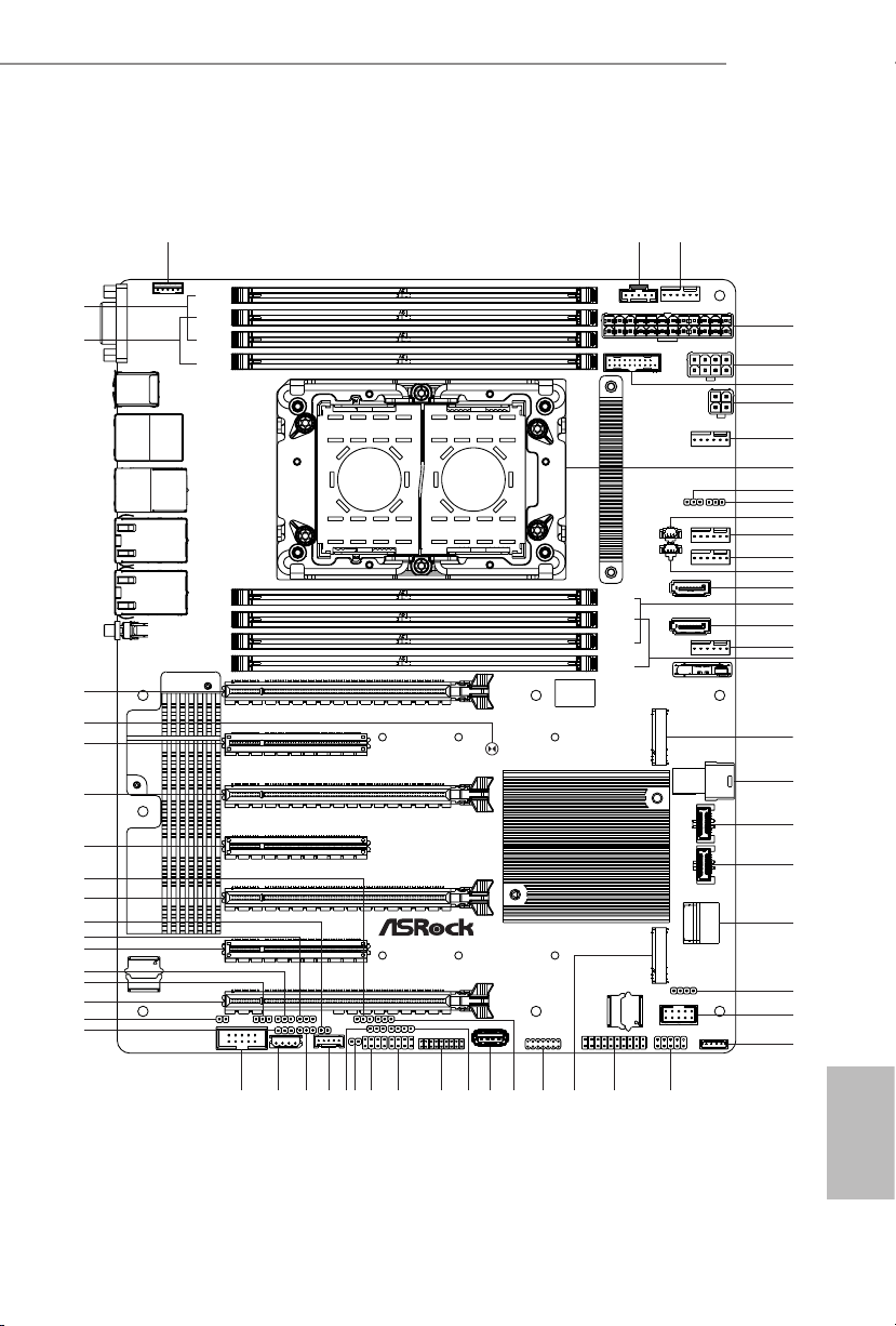
Motherboard Layout
12
15
16
10
11
13
14
17
20
18
19
21
23
24
22
25
26
27
28
59
57
55
54
56
49
47
45
50
51
52
53
61
60
58
C621A WS
VGA1
USB 3.2
Gen1
T: USB3_4
B:USB3_3
USB 3.2
Gen1
T: USB3_2
B:USB3_1
IPMI_LAN
1
CPU1_HSBP1
DDR4_B1
DDR4_A1
DDR4_D1
DDR4_C1
PSU_SMB1
USB3_5_6
3
2
FAN1
ATXPWR1
ATX12V1
4
5
6
ATX12V2
FAN2
7
8
9
LAN3
LAN4
LAN1
LAN2
UID1
BMC
48
ROM1
46
NMI_BTN2
COM1
PCIE7
PCIE6
PCIE5
PCIE4
PCIE3
PCIE2
CPU1
PECI1
C621A WS
ME_RECOVERY1
PASSWORD_CLEAR
ESPI_SHARE
BIOS_RECOVERY
IPMB1
ESPI_MODE1
BMC_SMB_1
41424344
ESPI_LPC_SEL1
CPU_VSENSE
SATAPWR2
SATAPWR1
DDR4_G1
DDR4_H1
DDR4_E1
DDR4_F1
CLRMOS1
PWM_CFG1
FAN3
FAN4
SATA_5
SATA_4
FAN5
BAT1
M2_1
SATA_0_3
USB31 _TC_1
USB31 _TC_2
SSATA_2_ 3
MINISAS_1
M2_2
PCIE1
SEC_OR1
R
T 1
SATA_SGPIO1
SSATA_SGPIO1
FRONT_LED_LAN34
TPM1
USB_1
TPM_BIOS_PH1
AUX_PANEL1
BIOS
ROM1
SPEAKER1
USB_2_3
PANEL1
RAID_1
29
3435 3236
39
40
333738
3031
English

English
No. Description
1 Backplane PCI Express Hot-Plug Connector (CPU1_HSBP1)
2 PSU SMBus Header (PSU_SMB1)
3 System Fan Connector (FAN1)
4 ATX Power Connector (ATXPWR1)
5 ATX 12V Power Connector (ATX12V1)
6 USB 3.2 Gen1 Header (USB3_5_6)
7 ATX 12V Power Connector (ATX12V2)
8 System Fan Connector (FAN2)
9 LGA 4189 CPU Socket (CPU1)
10 CPU VSENSE Header (CPU_VSENSE)
11 PWM Conguration Header (PWM_CFG1)
12 SATA DOM Power Connector (SATAPWR2)
13 System Fan Connector (FAN3)
14 System Fan Connector (FAN4)
15 SATA DOM Power Connector (SATAPWR1)
16 SATA3 DOM Connector (SATA_5)
17 2 x 288-pin DDR4 DIMM Slots (DDR4_E1, DDR4_G1)*
18 SATA3 DOM Connector (SATA_4)
19 System Fan Connector (FAN5)
20 2 x 288-pin DDR4 DIMM Slots (DDR4_F1, DDR4_H1)*
21 M.2 Socket (M2_1) (Type 2242/2280/22110)
22 Mini-SAS HD Connector (SATA_0_3)
23 Front Panel Type C USB 3.2 Gen2 Header (USB31_TC_1)**
24 Front Panel Type C USB 3.2 Gen2 Header (USB31_TC_2)**
25 SATA3 Connectors (SSATA_3)(Upper), (SSATA3_2)(Lower)**
26 Speaker Header (SPEAKER1)
27 USB 2.0 Header (USB_2_3)
28 Virtual RAID On CPUHeader (RAID_1)
29 System Panel Header (PANEL1)
30 Auxiliary Panel Header (AUX_PANEL1)
31 M.2 Socket (M2_2) (Type 2242/2280/22110)
32 TPM-SPI Header (TPM_BIOS_PH1)
33 Security Override Jumper (SEC_OR1)
2 3

No. Description
34 Vertical USB 2.0 Port (USB_1)
35 Front LAN LED Header (FRONT_LED_LAN34)
36 TPM Header (TPM1)
37 SATA SGPIO Connector (SATA_SGPIO1)
38 SATA SGPIO Connector (SSATA _ SGPIO1)
39 ermal Sensor Header (TR1)
40 MiniSAS HD SATA/PCIE Slection Jumper (MINISAS_1)
41 BMC SMBus Header (BMC_SMB_1)
42 ESPI Flash Sharing Jumper (ESPI_SHARE)
43 Intelligent Platform Management Bus Header (IPMB1)
44 COM Header (COM1)
45 BIOS Recovery Jumper (BIOS_RECOVERY1)
46 Non Maskable Interrupt Button (NMI_BTN2)
47 PCI Express 4.0 x16 Card Slot (PCIE1)
48 CPU PECI Mode Jumper (PECI1)
49 ME Recovery Jumper (ME_RECOVERY1)
50 PCI Express 4.0 x8 Card Slot (PCIE2)
51 Password Reset Jumper (PASSWORD_CLEAR)
52 BIOS Swap Override Header (ESPI_MODE1)
53 PCI Express 4.0 x16 Card Slot (PCIE3)
54 ESPI/LPC Selection Jumper (ESPI_LPC_SEL1)
55 PCI Express 4.0 x8 Card Slot (PCIE4)
56 PCI Express 4.0 x16 Card Slot (PCIE5)
57 PCI Express 4.0 x8 Card Slot (PCIE6)
58 Clear CMOS Pad (CLRMOS1)
59 PCI Express 4.0 x16 Card Slot (PCIE7)
60 2 x 288-pin DDR4 DIMM Slots (DDR4_A1, DDR4_C1)*
61 2 x 288-pin DDR4 DIMM Slots (DDR4_B1, DDR4_D1)*
*For DIMM in stallation and conguration instructions, please see p.21 (Installation of Memor y Modules
(DIMM)) for more detail s.
**2 Type-C USB headers (USB31_TC1/USB31_TC2) are shared with 2 SATA 7-pin headers (SSATA_2/SSATA_3)
(BOM option)
C621A WS
English

Onboard LED Indicators
2
3
4
5
6
7
1
English
4 5

No. Item Status Description
1 SB_PWR1 Green STB PWR ready
2 FAN _LE D1 Amber FAN1 failed
3 FAN _LE D2 Amber FAN2 failed
4 FAN _LE D3 Amber FAN3 failed
5 FAN _LE D4 Amber FAN4 failed
6 FAN _LE D5 Amber FAN5 failed
7 BLED1 Green BMC heartbeat LED
C621A WS
English

I/O Panel
3
5
1
No. Description No. Description
1 VGA Port (VGA1) 6 1G LAN RJ-45 Port (LAN4)**
2 USB 3.2 Gen1 Ports (USB3_3_4) 7 10G LAN RJ-45 Port (LAN1)***
3 LAN RJ-45 Port (IPMI_LAN)* 8 10G LAN RJ-45 Port (LAN2)***
4 USB 3.2 Gen1 Ports (USB3_1_2) 9 UID Switch (UID1)
5 1G LAN RJ-45 Port (LAN3)**
2
4
6
7
8
9
English
6 7

*ere are two LED next to the LAN port. Please refer to the table below for the LAN port
LED indications.
ACT/LINK LED
SPEED LED
LAN Por t
Dedicated IPMI LAN Port LED Indications
Activity / Link LED Speed LED
Status Description Status Description
O No Link O 10M bps connection or no
link
Blinking Orange Data Activity Yel low 100M bps connection
On Link Green 1G bps connection
**ere are two LEDs on each LAN port. Please refer to the table below for the LAN port
LED indications.
C621A WS
ACT/LINK LE D
ACT/LINK LE D
LAN Port
SPEED LE D
SPEED LE D
LAN Port (LAN3, LAN4) LED Indications
Activity / Link LED Speed LED
Status Description Status Description
O No Link O 10Mbps connection or
no link
Blinking Yellow Data Activity Yel low 100Mbps connection
On Link Green 1Gbps connection
English

***ere are two LEDs on each LAN port. Please refer to the table below for the LAN port
LED indications.
ACT/LINK LED
SPEED LED
LAN Por t
LAN Port (LAN1, LAN2) LED Indications
Activity / Link LED Speed LED
Status Description Status Description
O No Link O 100Mbps connection or
no link
Blinking Green Data Activity Yel low 1Gbps connection
On Link Green 10Gbps connection
English
8 9
Chapter 1 Introduction
ank you for purchasing ASRock C621A WS motherboard, a reliable motherboard
produced under ASRock’s consistently stringent quality control. It delivers excellent
performance with robust design conforming to ASRock’s commitment to quality and
endurance.
Becau se the motherboard specications and the BIOS soware might be updated, the
content of this documentation will be subject to change without notice. In case any
modications of this documentation occur, the upd ated version will be available on
ASRock’s website without further notice. If you require technical support related to
this motherboard, please vi sit our website for s pecic information about the model
you are using. You may nd the l atest VGA cards and CPU suppor t list on ASRock’s
website a s well. ASRock website http://www.asrock.com.
1.1 Package Contents
ASRock C621A WS Motherboard (ATX Form Factor)
•
ASRock C621A WS Quick Installation Guide
•
ASRock C621A WS Support CD
•
1 x TPM-SPI module
•
1 x CPU Non-Fabric Carrier (Optional)
•
1 x Mini SAS HD to 4*SATA Cable (60cm) (Optional)
•
1 x SATA Power Cable (80cm) (Opt ional)
•
1 x SATA3 Data Cable (60cm) (Optional)
•
1 x I/O Panel Shield
•
C621A WS
If any items are missing or appear damaged, contact your authorized deal er.
English

1.2 Specications
Platform
CPU
Chipset
Memory
Expansion
Slot
* If PCIE2 is occupied, PCIE3 will downgrade to x8 mode. If
PCIE4 is occupied, PCIE5 will downgrade to x8 mode. If PCIE6
is occupied, PCIE7 will downgrade to x8 mode.
ATX Form Factor
•
12 Layer PCB
•
2oz Copper PCB
•
Supports 3rd Generation Intel® Xeon® Scalable Processors
•
Intel® Socket 4189 (Socket P+)
•
Digi Power Design
•
7 Power Phase Design
•
Intel® C621A
•
Eight Channel Memory Technology (1DPC)
•
8 x DDR4 DIMM Slots
•
Supports DDR4 3200/2933/2666/2400/2133/1866 DDR4
•
RDIMM/ RDIMM-3DS/ LRDIMM/ LRDIMM-3DS/
Intel®Optane™ Persistent Memory 200 Series
Max. capacity of system memory: RDIMM: 64GB, LRDIMM:
•
128GB, RDIMM-3DS/ LRDIMM-3DS: 256GB
4 x PCIe Gen4x16 Slots (PCIE1/PCIE3/PCIE5/PCIE7)*
•
3 x PCIe Gen4x8 Slots (PCIE2/PCIE4/PCIE6)*
•
Aspeed® AST2500 BMC Controller
Graphics
LAN
English
•
Supports D-Sub with max. resolution up to 1920x1200 @
•
60Hz
2 x 10 Gigabit LAN 100/1000/2500/5000/10000 Mb/s (Intel®
X710-AT 2)
Supports Wake-On-LAN
•
Supports Lightning/ESD Protection
•
Supports Energy Ecient Ethernet 802.3az
•
Supports PXE
•
10 11

Storage
2 x Gigabit LAN 10/100/1000 Mb/s (Intel® I210)
Supports Wake-On-LAN
•
Supports Lightning/ESD Protection
•
Supports Energy Ecient Ethernet 802.3az
•
Supports PXE
•
1 x Dedicated IPMI (ASPEED AST2500)
Supports iKVM and vMedia
•
2 x SATA3 6.0 Gb/s Connectors
•
1 x Mini-SAS HD Connector
•
1 x Ultra M.2 Socket (M2_1, Key M), supports type
•
2242/2280/22110 SATA3 6.0 Gb/s & PCIe Gen3x4 (32 Gb/s)
modes*
1 x M.2 Socket (M2_2, Key M), supports type
•
2242/2280/22110 SATA3 6.0 Gb/s & PCIe Gen3x1 (8 Gb/s)
modes*
* Supports Intel® OptaneTM Tech nolo gy
* Supports NVMe SSD as boot disks
* Supports ASRock U.2 Ki
C621A WS
RAID
Rear Panel
I/O
Connector
Supports RAID 0, RAID 1, RAID 5 and RAID 10 for SATA
•
storage devices
Supports RAID 0, RAID 1, RAID 5 for M.2 NVMe storage
•
devices
1 x UID Switch w/ LED
•
1 x D-Sub Port
•
4 x USB 3.2 Gen1 Ports (Supports ESD Protection)
•
2 x RJ45 (10GbE), 2 x RJ45 (1GbE)
•
1 x RJ45 Dedicated IPMI LAN port
•
1 x SPI TPM Header
•
1 x LPC TPM Header
•
1 x COM Port Header
•
5 x System Fan Connectors (6-pin)
•
1 x 24 pin ATX Power Connector (Hi-Density Power
•
Connec tor)
English

1 x 8 pin 12V Power Connector (Hi-Density Power
•
Connec tor)
1 x 4 pin 12V Power Connector (Hi-Density Power
•
Connec tor)
1 x Vertical Type A USB 2.0
•
1 x USB 2.0 Header (Supports 2 USB 2.0 ports) (Supports
•
ESD Protection)
1 x USB 3.2 Gen1 Headers (Support 2 USB 3.2 Gen1 ports)
•
(Supports ESD Protection)
2 x USB3.2 Gen2 ports (2 Type-C headers)
•
2 x Front Panel Type C USB 3.2 Gen2 Headers (Supports ESD
•
Protection)
2 x SGPIO Headers
•
1 x Auxiliary Panel Header
•
1 x Intelligent Platform Management Bus Header
•
1 x Backplane PCI Express Hot-Plug Connector Header
•
1 x SMBus Header
•
1 x PMbus Header
•
1 x CPU HP-SMBus Connector
•
1 x ermal Sensor Header
•
1 x Virtual RAID On CPU Header
•
1 x BMC Heartbeat LED
•
1 x StandbyPower LED
•
5 x FanFail LED
•
1 x Non Maskable Interrupt Button Header
•
1 x Buzzer
•
1 x Dr. Debug with LED
•
AMI UEFI Legal BIOS
BIOS
Feature
Hardware
Monitor
English
•
ACPI 5.0 Compliant wake up events
•
SMBIOS 2.3 Support
•
Temperature Sensing: CPU, PCH, MB, Card Side
•
Fan Tachometer: CPU, Rear, Front Fan Tachometer
•
Quiet Fan (Auto adjust chassis fan speed by CPU
•
temperature): CPU Fan
Fan Multi-Speed Control: CPU, Rear, Front Fan
•
Voltage Monitoring: CPU1_PVCCIN, PVDDQ_
•
ABCD,PVDDQ_EFGH, 1.05V_PCH,1.8V_PCH,
+BAT,PVNN_PCH, 3.3V,5V,12V,3.3VSB, 5VSB
12 13
OS
Microso® Windows®
10 64-bit / 11 64-bit
•
Server 2016 (64 bit)
•
Server 2019 (64 bit)
•
Server 2022 (64 bit)
•
Linux®:
Red Hat Enterprise Linux Server 7.9 (64 bit) / 8.3 (64 bit)
•
CentOs 7.9 (64 bit) / 8.3 (64 bit)
•
SUSE Enterprise Linux Server 12 SP5 (64 bit) / 15 SP2 (64 bit)
•
Ubuntu 20.04.1 (64 bit) / 20.10 (64 bit)
•
Hypervisor:
VMWare® ESXi 6.7 U3 / vSphere 6.7 U3
•
VMWare® ESXi 7.0.U1c / vSphere 7.0.U1c
•
Hyper-V Winders Server 2016
•
Hyper-V Winders Server 2019
•
* Please refer to our website for the latest OS suppor t list.
FCC, CE
Certications
* For detailed product information, please visit our website: http://www.asrock .com
•
ErP/EuP ready (ErP/EuP ready power supply is required)
•
Please realize that the re is a certain risk involved with overclocking, including
adjusting the setting in the BIOS, applying Untied Overclocking Technology, or using
third-party overclocking tool s. Overclocking may aect your system’s stability, or
even cause damage to the components and devices of your system. It should be done
at your own risk and expense. We are not responsible for possible damage caused by
overclocking.
Chapter 2 Installation
is is an ATX form factor (12” x 9.6”, 30.5 cm x 24.4 cm) motherboard. Before you install
the motherboard, study the conguration of your chassis to ensure that the motherboard
ts into it.
Make sure to unplug the power cord before installing or removing the motherboard . Failure
to do so may cause physical injuries to you and d amages to motherboard components.
2.1 Screw Holes
Place screws into the holes indicated by circles to secure the motherboard to the chassis.
Do not over-tighten the screws! Doing so may damage the motherboard.
2.2 Pre-installation Precautions
Take note of the following precautions before you insta ll motherboard components or
change any motherboard settings.
1. Unplug the power cord from the wall socket before touching any components.
2. To avoid damaging the motherboard’s components due to static electricity, NEVER
place your motherboard directly on the carpet or the like. Also remember to use a
grounded wrist strap or touch a safety grounded object before you handle the components.
3. Hold components by the edges and do not touch the ICs.
4. Whenever you uninstall any component, place it on a grounded anti-static pad or in
the bag that comes with the component.
5. When placing screws into the screw holes to secure the motherboard to the chassis,
please do not over-tighten the screws! Doing so may damage the motherboard.
Before you install or remove any component, ensure that the power is switched o or the
power cord is detached f rom the power supply. Failure to do so may cau se severe damage to
the motherboard, peripherals, and/or components.
English
14 15
2.3 Installing the CPU and Heatsink
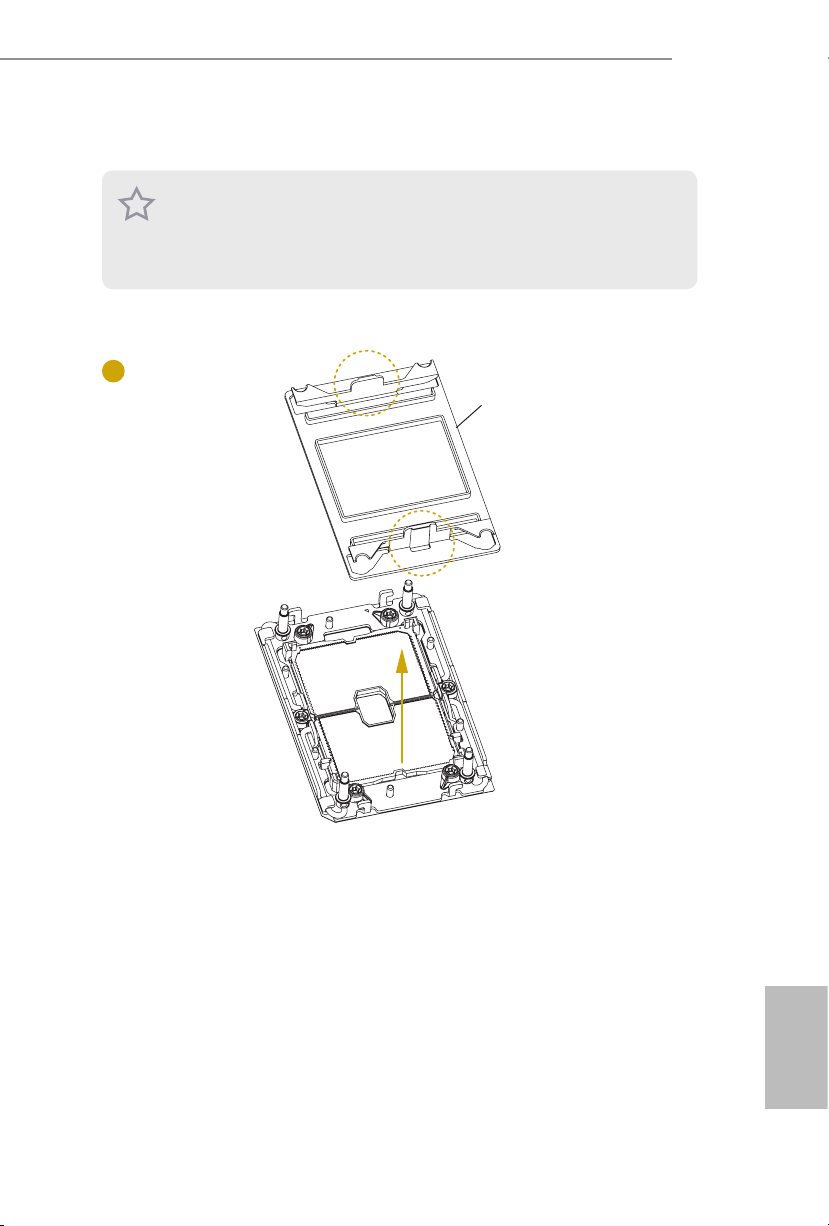
1. Before you insert the CPU into the socket, please check if the PnP cap is on the socket ,
if the CPU sur face is unclean, or if there are any bent pins in the socket. Do not force to
inser t the CPU into the socket if above situation is found. Otherwise, the CPU will be
seriously damaged.
2. Unplug all power cables before in stalling the CPU.
1
C621A WS
Socket Dust Cover
English
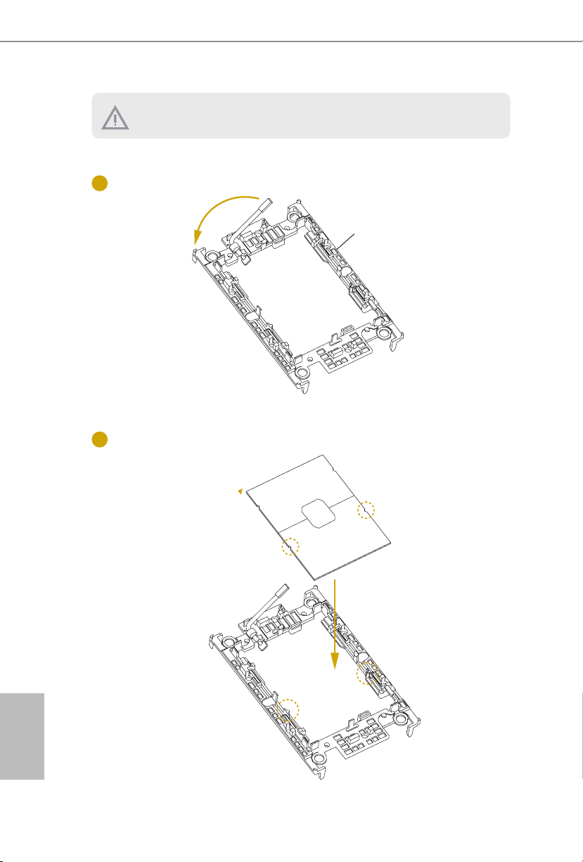
1. Before you installed the heatsink , you need to spray thermal interface material between the CPU
and the heatsink to improve heat dissipation.
2. Illustration in this documentation are examples only. Heatsink or fan cooler type may dier.
2
CPU Carrier
3
English
16 17

C621A WS
4
5
180
o
English

6
7
English
CPU Carrier
18 19
C621A WS
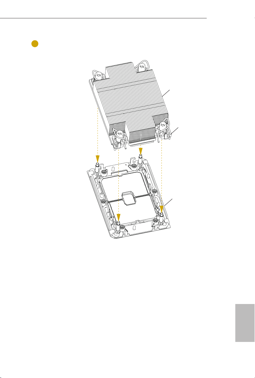
8
Heatsink
CPU Carrier
Socket
English

9
10
English
20 21

2.4 Installation of Memory Modules (DIMM)
is motherboard provides eight 288-pin DDR4 (Double Data Rate 4) DIMM slots in two
groups, and supports Eight Channel Memory Technology.
CPU1
A1 B1 C1 D1 E1 F1 G1 H1
1 DIMM
2 DIMMS
4 DIMMS
8 DIMMS
1. It is not allowed to install a DDR, DDR 2 or DDR3 memory module into a DDR4 slot;
2. For eight channel conguration , you always need to in stall identical (the same brand,
# # # # # # # #
otherwise, this motherboard and DIMM may be damaged.
speed , size and chip-type) DDR4 DIMM pairs.
#
# #
# # # #
C621A WS
English

1
2
3
English
22 23

2.5 Expansion Slots (PCI Express Slots)
ere are 7 PCIe slots on this motherboard.
PCIE slot:
PCIE1, PCIE3, PCIE5 and PCIE7 (PCIE 4.0 x16 slot, from CPU1) are used for PCIe x16
lane width cards.
PCIE2, PCIE4 and PCIE6 (PCIE 4.0 x8 slot, from CPU1) are used for PCIe x8 lane width
cards.
Slot Generation Mechanical Electrical Source
PCIE7 4.0 x16 x16 CPU1
PCIE6 4.0 x8 x8 CPU1
PCIE5 4.0 x16 x16 CPU1
PCIE4 4.0 x8 x8 CPU1
PCIE3 4.0 x16 x16 CPU1
PCIE2 4.0 x8 x8 CPU1
PCIE1 4.0 x16 x16 CPU1
PCIe Slot Congurations
C621A WS
PCIE2 PCIE3
Single PCIE Card N/A x16
Two PCIE Cards x8 x8
PCIE4 PCIE5
Single PCIE Card N/A x16
Two PCIE Cards x8 x8
PCIE6 PCIE7
Single PCIE Card N/A x16
Two PCIE Cards x8 x8
English

Installing an expansion card
Step 1. Before installing an expansion card, please make sure that the power
supply is switched o or the power cord is unplugged. Please read the
documentation of the expansion card and make necessary hardware
settings for the card before you start the installation.
Step 2. Remove the system unit cover (if your motherboard is already installed
in a chassis).
Step 3. Remove the bracket facing the slot that you intend to use. Keep the
screws for later use.
Step 4. Align the card connector with the slot and press rmly until the card is
completely seated on the slot.
Step 5. Fasten the card to the chassis with screws.
English
Step 6. Replace the system cover.
24 25
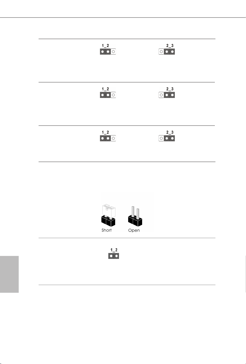
2.6 Jumper Setup
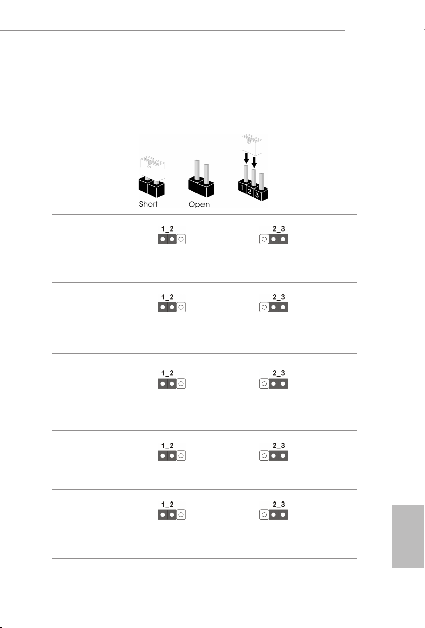
e illustration shows how jumpers are setup. When the jumper cap is placed on
the pins, the jumper is “Short”. If no jumper cap is placed on the pins, the jumper
is “Open”. e illustration shows a 3-pin jumper whose pin1 and pin2 are “Short”
when a jumper cap is placed on these 2 pins.
MiniSAS HD SATA/PCIE
Selection Jumper
(3-pin MI NISA S_1)
(see p.1, No. 40)
CPU PECI Mode Jumper
(3-pin PECI1)
(see p.1, No. 48)
SATA (Default)
CPU PECI connected to
PCH
PCIE
CPU PECI connected to
BMC (Default)
C621A WS
Security Override Jumper
(3-pin SEC_OR1)
(see p.1, No. 33)
ME Recovery Jumper
(3-pin ME_RECOVERY1)
(see p.1, No. 49)
Password Reset Jumper
(3-pin PASSWORD_
CLEAR)
(see p.1, No. 51)
Descriptor Security
Override
Normal Mode (Default)
Normal Mode (Default)
Not override (Default)
ME Recovery Mode
Password Clear
English

BIOS Recovery Jumper
(3-pin BIOS _R ECOVERY1)
(see p.1, No. 45)
ESPI/LPC Selection Jumper
(3-pin ES PI_LPC _S EL1)
(see p.1, No. 54)
ESPI Flash Sharing Jumper
(3-pin ESPI_SHARE)
(see p.1, No. 42)
e illustration shows how jumpers are setup. When the jumper cap is placed on
the pins, the jumper is “Short”. If no jumper cap is placed on the pins, the jumper is
“Open”.
Normal Mode (Default)
ESPI (Default)
Master ESPI Flash Sharing
(Default)
Recover BIOS
LPC
Slave ESPI Flash Sharing
BIOS Swap Override
Jumper
(ESPI_MODE1)
(see p.1, No. 52)
2-pin Jumper
Open: Disable Override (Default)
Short: Enable Override
English
26 27
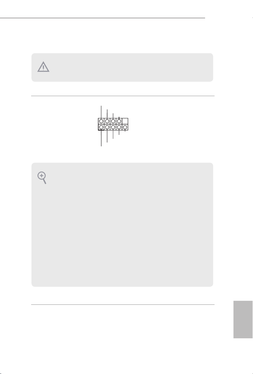
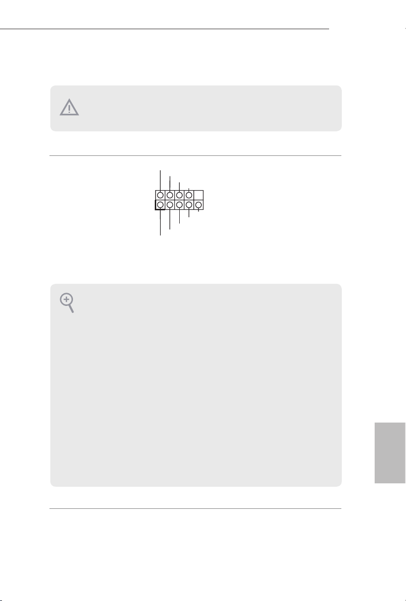
2.7 Onboard Headers and Connectors
Onboard headers and connectors are NOT jumpers. Do NOT place jumper caps over these
heade rs and connectors. Placing jumper caps over the headers and connectors will cause
permanent damage to the motherboard.
C621A WS
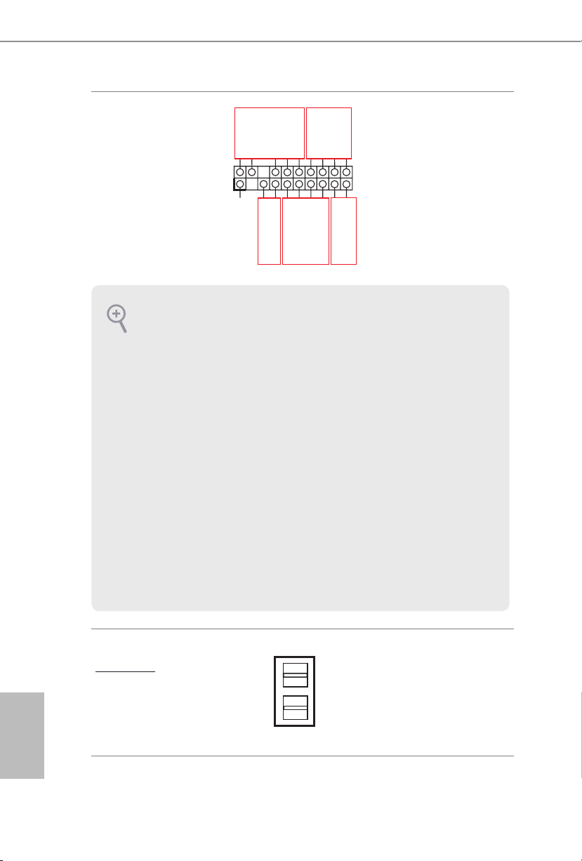
System Panel Header
(9-pi n PANEL1)
(see p.1, No. 29)
PWRBTN (Power Switch):
Connec t to the power switch on the chassi s front panel. You may congure the way to tur n
o your system using the power switch.
RESET (Reset Switch):
Connec t to the reset switch on the chassi s front panel. Press the reset sw itch to restart the
computer if the computer f reezes and fails to per form a normal restar t.
PLED (Syste m Power LED):
Connec t to the power status indicator on the chassis front panel. e LED i s on when the
system is operating. e LED is o when the system is in S4 sleep state or powered o (S5).
HDLED (Ha rd Drive Activity LED):
Connec t to the hard drive activity LED on the chassis front panel. e LED is on when the
hard drive is reading or wr iting data.
e front panel design may dier by chassis. A front panel module mainly consists of powe r
switch, reset switch , power LED, hard dr ive activity LED, speaker and etc. When connecting your chassi s front panel module to thi s header, make sure the wire a ssignments and the
pin assignments are matched correctly.
1
PLED+
PLED-
HDLED-
HDLED+
PWRBTN#
GND
GND
RESET#
GND
Co nnec t t he power switch,
reset switch and system status
indicator on the chassis to this
header according to the pi n
assignments. Particularly note
the positive and negative pins
before connecting the cables.
English
Auxiliary Panel Header
1
A
B
(18-pin AUX_PANEL1)
(see p.1, No. 30)
is header supports multiple
functions on the front panel,
SMB _Aler t
SMB _CLK
LAN 1_LIN K
+3V SB
GND
SMB _DATA
including the front panel SMB,
LED _PWR
LED _PWR
LAN 2_LIN K
internet status indicator and
chassis intrusion pin.
GND
+5V SB
CAS EOPEN
C
GND
LOC ATORBTN #
LOC ATORLED 1-
LOC ATORLED 1+
E
Sys tem F ault LED+
D
Sys tem F ault LED-
A. Front panel SMBus connecting pin (6-1 pin FPSMB)
is header allows you to connect SMBus (System Management Bus) equipment. It can
be used for communication between peripheral equipment in the system, which ha s slower
transmission rates, and power management equipment.
B. Internet status indicator (2-pin LAN1_ LED, LAN2_LED)
ese two 2-pin headers allow you to use the Gigabit internet indicator cable to connect
to the LAN status indicator. When this indicator ickers , it means that the internet is properly connected.
C. Chassis intrusion pin (2-pin CHASSIS)
is header is provided for host computer chassis with chassis intrusion detection d esigns.
In addition, it must also work with e xternal detection equipment, such as a chassis intrusion detection sensor or a microswitch. When this function is activated, if any chassis
component movement occ urs, the sensor will immediately detect it and send a signal to this
heade r, and the system will then record this chassi s intrusion event. e default setting is
set to the CASEOPEN and GND pin; this function is o.
D. Locator LED (4-pin LOCATOR)
is header is for the locator switch and LED on the front panel.
E. System Fault LED (2-pin LOCATOR)
is header is for the Fault LED on the system.
English
Mini-SAS HD Connector
Right-A ngle:
(SATA_ 0_3)
(see p.1, No. 22)
SATA_0_3
is connector supports
MiniSAS-to-SATA
data cables for internal
storage devices with up
to 6.0 Gb/s data transfer
rate.
28 29
C621A WS
65 4321
NC
1
Dummy
IntA_PA_D+
USB 3.2 Gen1 Header
(19-pin USB3_5_6)
(see p.1, No. 6)
System Fan Connectors
(6-pi n FAN1)
(6-pin FAN2)
(6-pin FAN3)
(6-pin FAN4)
(6-pin FAN5)
(see p.1, No. 3, 8, 13, 14,
19)
Front Panel Type C USB
3.2 Gen2 Headers
(20-pin USB31_TC_1)
see p.1, No. 23)
(20-pin USB31_TC_2)
(see p.1, No. 24)
IntA_PA_D-
GND
IntA_PA_SSTX+
GND
IntA_PB_D-
IntA_PB_D+
IntA_PA_SSTX-
GND
IntA_PA_SSRX+
IntA_PA_SSRX-
Vbus
IntA_PB_SSRX-
IntA_PB_SSRX+
GND
IntA_PB_SSTX-
IntA_PBA_SSTX+
GND
FAN_VOLTAGE
FAN_SPEED
FAN_SPEED_CONTROL
SENSOR
Vbus
Besides four default USB 3.2
Gen1 ports on the I/O panel,
there is one USB 3.2 Gen1
header on this motherboard.
is USB 3.2 Gen1 header can
support two USB 3.2 Gen1
ports.
Please connect fan cables to the
fan connectors and match the
black wire to the ground pin.
All fans support Fan Control.
ere are two Front Panel Type
C USB 3.2 Gen2 Header on this
motherboard. ese headers
are used for connecting
USB 3.2 Gen2 modules for
additional USB 3.2 Gen2 ports.
*2 Type-C USB headers (USB31_TC1/
USB31_TC2) are shared with 2 SATA
7-pin headers (SSATA_2/SSATA_3)
(BOM option).
USB 2.0 Connector
(USB_1)
(see p.1, No. 34)
ere is one vertical USB 2.0
port on this motherboard.
English

USB 2.0 Header
USB_PWR
USB_PWR
GND
+12V
SMB _DA TA _MA I
#
(9-pin USB_2_3)
(see p.1, No. 27)
ATX Power Connector
(24-pin ATXPWR1)
(see p.1, No. 4)
P-
P+
GND
DUMMY
is is one header on
this motherboard. is
USB 2.0 header can
1
3V
3V
13
3V
-12V
GND
P+
P-
PWROK_PS
GND
5V
GND
PSON#
5VSB
GND
GND
12V
5V
GND
GND
GND
N/A
support two ports.
is motherboard provides a
12V
3V
24-pin ATX power connector.
121
To use a 20-pin ATX power
supply, please plug it along Pin
24
5V5V5V
GND
1 and Pin 13.
ATX 12V Power
Connectors
(8-pin ATX12V1)
(see p.1, No. 5)
(4-pin ATX12V2)
(see p.1, No. 7)
SATA DOM Power
Connector
(3-pin SATAPWR1)
(see p.1, No. 15)
(3-pin SATAPWR2)
(see p.1, No. 12)
GND
1
5
1
3
4
8
12V
2
4
is motherboard provides
one 8-pin and one 4-pin ATX
12V power connectors.
Please use a SATA power cable
+5V
GND
to connect this SATA Power
Connector and your SATA
HDD for supplying power
from the motherboard, when
using DC-IN mode without
SATA power supply.
English
TPM Header
(17-pi n TPM1)
(see p.1, No. 36)
GND
LAD 0
LAD 3
+3V
+3V SB
D
GN
SER IRQ#
S_P WRD WN#
PCI RST #
N
GND
LAD 1
LAD 2
is connector supports
K
Trusted Platform Module
LFR AME
PCI CL
(TPM) system, which can
1
securely store keys, digital
certicates, passwords, and
D
data. A TPM system also helps
GN
enhance network security,
protects digital identities, and
SMB _CL K_ MAI N
ensures platform integrity.
30 31

C621A WS
ALERT
IPMB_SDA
No Connect
BMC_SMB_PRESENT_1_N
P
TPM-SPI Header
(13-pin TPM_BIOS_PH1)
(see p.1, No. 32)
PSU SMBus Header
(5-pin PSU_SMB1)
(see p.1, No. 2)
Intelligent Platform
Management Bus Header
(4-pin IPMB1)
(see p.1, No. 43)
TPM_CS#
SPI_RST
SPI PIRQ
SMBCLK
1
SMBDATA
IPMB_SCL
GND
RSMRST#
GND
MOSI
SPI_CLK
GND
MISO
X
+3V
SPI_WP
SPI_CS
+3.3V
SPI_HOLD
is connector supports
Trusted Platform Module
(TPM) system for SPI
1
interface, which can securely
store keys, digital certicates,
passwords, and data. A TPM
system also helps enhance
network security, protects
digital identities, and ensures
platform integrity.
PSU SMBus monitors the
status of the power supply, fan
and system temperature.
This 4-pin connector is used
to provide a cabled base-board
or front panel connection for
value added features and 3rdparty add-in cards, such as
Emergency Management cards,
that provide management
features using the IPMB.
Baseboard Management
Controller SMBus Header
(5-pin BMC_SMB_1)
(see p.1, No. 41)
CPU HP-SMBus Connector
(5-pin CPU1_HSBP1)
(see p.1, No. 1)
Power
BMC_SMBCLK7
GND
BMC_SMBDATA7
CPU_HP_SCL
CPU_HP_SDA
0_HP_ALERT_L
GND
e header is used for the SM
BUS devices.
+3V
is header is used for the hot
plug feature of HDDs on the
backplane.
1
English

Serial ATA3 DOM
Connectors
(SATA_4)
(see p.1, No. 18)
(SATA_5)
(see p.1, No. 16)
SATA _ 5
SATA _ 4
e SATA3 DOM connectors
support both SATA DOMs
(Disk-On-Module) and SATA
data cables for internal storage
devices.
Serial ATA3 Connectors
Ver tica l:
(SATA_4)
(see p.1, No. 18)
(SATA_5)
(see p.1, No. 16)
Serial Port Header
(9-pin COM1)
(see p.1, No. 44)
Clear CMOS Pad
(CLRMO S1)
(see p.1, No. 58)
Non Maskable Interrupt
Button Header
(NMI_BTN2)
(see p.1, No. 46)
SATA _ 5
SATA _ 4
TTXD1
GND
RRTS#1
RRI#1
CCTS#1
DDSR#1
DDTR#1
1
CONTROL
DDCD#1
RRXD1
GND
ese two SATA3 connectors
support SATA data cables for
internal storage devices with
up to 6.0 Gb/s data transfer
rate.
*2 Type-C USB headers (USB31_TC1/
USB31_TC2) are shared with 2 SATA
7-pin headers (SSATA_2/SSATA_3)
(BOM option).
is COM header supports a
1
serial port module.
is allows you to clear the
data in CMOS. To clear CMOS,
take out the CMOS battery and
short the Clear CMOS Pad.
Please connect a NMI dev ice
to this header.
English
32 33

C621A WS
TR1
LAN3_LINK
SCLOCK
GND
GND
H_VSENSEINPMAX_CPU1
ermal Sensor Header
(2-pin TR 1)
(see p.1, No. 39)
Front LAN LED Header
(4-pi n FRONT_LED_
LAN34)
(see p.1, No. 35)
Chassis Speaker Header
(4-pin SPEAKER1)
(see p.1, No. 26)
Serial General Purpose
Input/Output Headers
(7-pin SATA _ SGPIO1)
(see p.1, No. 37)
(7-pin SSATA_SGPIO1)
(see p.1, No. 38)
1
DUMMY
1
1
LED_PWR
+5V
SLOAD
GND
1
SDATAOUT
LAN4_LINK
LED_PWR
SPEAKER
DUMMY
Please connect the thermal
sensor cable to either pin 1-2
or pin 2-3 and the other end to
the device which you wish to
monitor its temperature.
is 4-pin connector is used
for the front LAN status
indicator.
Please connect the chassis
speaker to this header.
e headers support Serial
Link interface for onboard
SATA connections.
PWM Conguration
Header
(3-pin PW M _CFG1)
(see p.1, No. 11)
CPU VSENSE Header
(3-pin CPU_VSENSE)
(see p.1, No. 10)
1
1
GND
SMB_DATA_VSB
SMB_CLK_VSB
GND
is header is used for PWM
congurations.
is header is used to detect
CPU1 VSENSE.
English

Virtual RAID On CPU
GND
Header
(4-pin RAID_1)
(see p.1, No. 28)
VROC RAID KEY
1
is connector supports Intel®
Virtual RAID on CPU and
GND
+3VSB
NVME/AHCI RAID on CPU
PCIE.
With the introduction of the Intel VROC product, there are three modes of operation:
SKU HW key required Key features
• Pass-thru only (no RAID)
Pass-thru Not needed
• LED Management
• Hot Plug Support
• RAID 0 support for Intel Fultondale NVMe SSDs
English
Standard VROCSTANMOD
Premium
VROCPREMMOD
• Pass-thru SKU features
• RAID 0, 1, 10
• Standard SKU features
• RAID 5
ISS
VROCISSDMOD
• RAID 5 Write Hole Closure
*Only Intel SSDs are supported.
*For further details on VROC, please refer to the ocial information released by Intel.
34 35

2.8 Unit Identication purpose LED/Switch
With the UID button, You are able to locate the server you’re working on from behind
a rack of servers.
C621A WS
Unit Identication
purpose LED/Switch
(U ID1)
(see p.6, No. 9)
When the UID button on the
front or rear panel is pressed,
the front/rear UID blue LED
indicator will be truned on.
Press the UID button again to
turn o the indicator.
2.9 Driver Installation Guide
To install the drivers to your system, please insert the support CD to your optical
drive rst. en, the drivers compatible to your system can be auto-detected and listed
on the support CD driver page. Please follow the order from top to bottom to install
those required drivers. erefore, the drivers you install can work properly.
English

2.10 M.2_SSD (NGFF) Module Installation Guide
3
The M.2, also known as the Next Generation Form Factor (NGFF), is a small size and
versatile card edge connector that aims to replace mPCIe and mSATA.
e Ultra M.2 Socket (M2_1) supports a M.2 SATA3 6.0 Gb/s module or a M.2 PCI Express
module up to Gen3 x4 (32Gb/s). e M.2 Socket (M2_2) supports a M.2 SATA3 6.0 Gb/s
module or a M.2 PCI Express module up to Gen3 x1 (8 Gb/s).
Installing the M.2_SSD (NGFF) Module
Step 1
Prepare a M.2_SSD (NGFF) module
and the screw.
Step 2
English
2
1
ABC
No. 1 2 3
Nut Location A B C
PCB Length 4.2cm 8cm 11cm
Module Type Typ e 22 42 Type 228 0 Type 22110
Depending on the PCB type and
length of your M.2_SSD (NGFF)
module, nd the corresponding nut
location to be used.
36 37
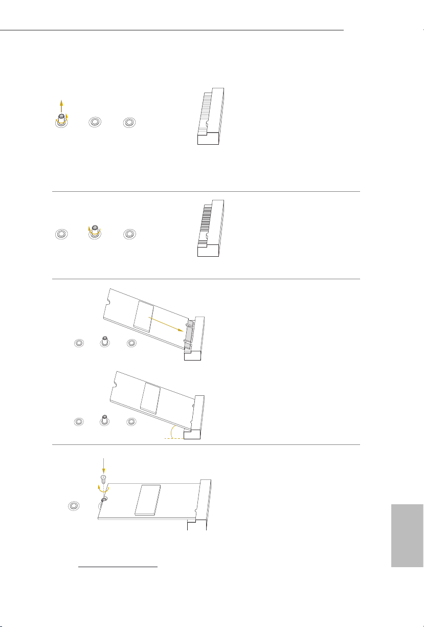
C621A WS
Step 3
Move the stando based on the
module type and length.
ABC
ABC
ABC
Skip Step 3 and 4 and go straight
to Step 5 if you are going to use the
default nut.
Otherwise, release the stando by
hand.
Step 4
Peel o the yellow protective lm on
the nut to be used. Hand tighten the
stando into the desired nut location
on the motherboard.
Step 5
Align and gently insert the M.2
(NGFF) SSD module into the M.2
slot. Please be aware that the M.2
(NGFF) SSD module only ts in one
orientation.
ABC
o
20
Step 6
Tighten the screw with a screwdriver
to secure the module into place.
Please do not overtighten the screw as
NUT1NUT2C
this might damage the module.
For the latest updates of M.2_SSD (NFGG) module support list, please visit our website for
details: http://www.asrock.com
English

1 Einleitung
Vielen Dank, dass Sie sich für das C621A WS von ASRock entschieden haben – ein
zuverlässiges Motherboard, das konsequent unter der strengen Qualitätskontrolle von
ASRock hergestellt wurde. Es liefert ausgezeichnete Leistung mit robustem Design, das
ASRock Streben nach Qualität und Beständigkeit erfüllt.
Da die technischen Daten des Motherboards sowie die BIOS-Soware aktualisiert werden
können, kann der Inhalt dieser Dokumentation ohne Ankündigung geändert werden.
Falls diese Dokumentation irgendwelchen Änderungen unterliegt, wird die aktualisierte
Version ohne weitere Hinweise auf der ASRock-Webseite zur Verfügung gestellt. Sollten Sie
technische Hilfe in Bezug auf dieses Motherboard benötigen, erhalten Sie auf unserer Webseite
spezischen Informationen über das von Ihnen verwendete Modell. Auch nden Sie eine
aktuelle Liste unterstützter VGA-Karten und Prozessoren auf der ASRock-Webseite.
ASRock-Webseite http://www.asrock.com.
1.1 Lieferumfang
ASRock C621A WS-Motherboard (ATX-Formfaktor)
•
ASRock C621A WS-Schnellinstallationsanleitung
•
ASRock C621A WS-Support-CD
•
1 x TPM-SPI-Modul
•
1 x CPU-Non-Fabric-Träger (optional)
•
1 x Mini-SAS-Festplatte-zu-4-SATA-Kabel (60 cm) (optional)
•
1 x SATA-Stromkabel (80 cm) (optional)
•
1 x SATA-III-Datenkabel (60 cm) (optional)
•
1 x E/A-Blendenabschirmung
•
Deutsch
38
Wenden Sie sich an Ihren autorisierten Händler, falls etwas fehlen oder beschädigt sein sollte.

1.2 Technische Daten
ATX-Formfaktor
Plattform
Prozessor
Chipsatz
Speicher
•
12-Layer-PCB
•
Platine mit zwei Unzen Kupfergehalt
•
Skalierbare Intel® Xeon®-Prozessoren der 3. Generation
•
Intel®-Sockel 4189 (Sockel P+)
•
Digi Power design
•
7-Leistungsphasendesign
•
Intel® C621A
•
Acht-Kanal-Speichertechnologie (1DPC)
•
8 x DDR4-DIMM-Steckplätze
•
Unterstützt persistenten DDR4-3200/2933/2666/2400/2133/1866-
•
DDR4-RDIMM/ RDIMM-3DS/LRDIMM/LRDIMM-3DS/Intel®
Optane™-Speicher der 200er-Serie
Systemspeicher, max. Kapazität: RDIMM: 64 GB, LRDIMM:
•
128 GB, RDIMM-3DS/ LRDIMM-3DS: 256GB
C621A WS
Erweiterungssteckplatz
Grakkarte
LAN
4 x PCIe Gen4x16-Steckplätze (PCIE1/PCIE3/PCIE5/PCIE7)*
•
3 x PCIe Gen4x8-Steckplätze (PCIE2/PCIE4/PCIE6)*
•
* Wenn der PCIE2-Steckplatz belegt ist, wird PCIE3 auf den x8-Modus
herabgesetzt. Wenn der PCIE4-Steckplatz belegt ist, wird PCIE5 auf
den x8-Modus herabgesetzt. Wenn der PCIE6-Steckplatz belegt ist,
wird PCIE7 auf den x8-Modus herabgesetzt.
Aspeed® AST2500-BMC-Controller
•
Unterstützt D-Sub mit maximaler Auösung von 1920 x 1200 bei
•
60 Hz
2 x 10 Gigabi- LAN 100/1000/2500/5000/10000 Mb/s
(Intel® X710-AT2)
Unterstützt Wake-On-LAN
•
Unterstützt Schutz gegen Blitzschlag/elektrostatische Entladung
•
Unterstützt energieezientes Ethernet 802.3az
•
Unterstützt PXE
•
Deutsch
39

Speicher
RAID
2 x Gigabit-LAN 10/100/1000 Mb/s (Intel® I210)
Unterstützt Wake-On-LAN
•
Unterstützt Schutz gegen Blitzschlag/elektrostatische Entladung
•
Unterstützt energieezientes Ethernet 802.3az
•
Unterstützt PXE
•
1 x Dedizierte IPMI (ASPEED AST2500)
Unterstützt iKVM and vMedia
•
2 x SATA-III-6,0-Gb/s-Anschlüsse
•
1 x Mini-SAS-HD-Anschluss
•
1 x Ultra-M.2-Sockel (M2_1, Key M), unterstützt Typ-
•
2242/2280/22110-SATA-III-6,0-Gb/s- und PCIe-Gen3x4- (32 Gb/s)
Modi*
1 x M.2-Sockel (M2_2, Key M), unterstützt Typ-2242/2280/22110-
•
SATA-III-6,0-Gb/s- und PCIe-Gen3x1- (8 Gb/s) Modi*
* Unterstützt Intel® OptaneTM-Technologie
* Unterstützt NVMe-SSD als Bootplatte
* Unterstützt ASRock U.2-Kit
Unterstützt RAID 0, RAID 1, RAID 5 und RAID 10 für SATA-
•
Speichergeräte
Unterstützt RAID 0, RAID 1, RAID 5 für M.2-NVMe-
•
Speichergeräte
Deutsch
40
Rückblende,
E/A
Anschluss
1 x UID-Schalter mit LED
•
1 x D-Sub-Port
•
4 x USB-3.2-Gen1-Ports (unterstützt Schutz gegen elektrostatische
•
Entladung)
2 x RJ45 (10 GbE), 2 x RJ45 (1 GbE)
•
1 x dedizierter RJ45-IPMI-LAN-Port
•
1 x SPI-TPM-Stileiste
•
1 x LPC-TPM-Stileiste
•
1 x COM-Anschluss-Stileiste
•
5 x Systemlüeranschluss (6-polig)
•
1 x 24-poliger ATX-Netzanschluss (hochdichter Netzanschluss)
•

1 x 8-poliger 12-V-Netzanschluss (hochdichter Netzanschluss)
•
1 x 4-poliger 12-V-Netzanschluss (hochdichter Netzanschluss)
•
1 x Vertikal, Typ A, USB 2.0
•
1 x USB 2.0-Stileiste (unterstützt zwei USB 2.0-Ports)
•
(unterstützt Schutz gegen elektrostatische Entladung)
1 x USB 3.2 Gen1-Stileiste (unterstützt 2 USB 3.2 Gen1-Ports)
•
(unterstützt Schutz gegen elektrostatische Entladung)
2 x USB-3.2-Gen2-Ports (2 Type-C-Stileisten)
•
2 x USB-3.2-Gen2-Type-C-Stileisten an der Frontblende
•
(unterstützt Schutz gegen elektrostatische Entladung)
2 x SGPIO-Stileisten
•
1 x Zusatzblendenstileiste
•
1 x Intelligente-Plattformverwaltung-Bus-Stileiste
•
1 x PCI-Express-Hot-Plug-Anschluss-Stileiste an der Rückblende
•
1 x SMBus-Stileiste
•
1 x PMbus-Stileiste
•
1 x CPU-HP-SMBus-Anschluss
•
1 x ermosensor-Stileiste
•
1 x Virtual RAID an der CPU-Stileiste
•
1 x BMC-Heartbeat-LED
•
1 x Bereitschas-LED
•
5 x Lüerausfall-LED
•
1 x nicht-maskierbare Unterbrechungstaste-Stileiste
•
1 x Summer
•
1 x Dr. Debug mit LED
•
C621A WS
BIOSFunktion
Hardwareüberwachung
AMI UEFI Legal BIOS
•
ACPI 5.0-konforme Aufweckereignisse
•
SMBIOS 2.3-Unterstützung
•
Temperaturerkennung: CPU, PCH, MB, Kartenseite
•
Lüertachometer: CPU, Rückseite, Vorderseite Lüertachometer
•
Lautloser Lüer (automatische Anpassung der
•
Gehäuselüergeschwindigkeit durch CPU-Temperatur): CPULüer
Mehrfachgeschwindigkeitssteuerung: CPU, Rückseite, Vorderseite
•
Lüer
Spannungsüberwachung: CPU1_PVCCIN, PVDDQ_
•
ABCD,PVDDQ_EFGH, 1,05V_PCH, 1,8V_PCH, +BAT,
PVNN_PCH, 3,3V, 5V, 12V, 3,3VSB, 5VSB
Deutsch
41

Betriebssystem
Microso® Windows®
10 64-bit / 11 64 Bit
•
Server 2016 (64 Bit)
•
Server 2019 (64 Bit)
•
Server 2022 (64 Bit)
•
Linux®:
Red Hat Enterprise Linux Server 7.9 (64 Bit) / 8.3 (64 Bit)
•
CentOs 7.9 (64 Bit) / 8.3 (64 Bit)
•
SUSE Enterprise Linux Server 12 SP5 (64 Bit) / 15 SP2 (64 Bit)
•
Ubuntu 20.04.1 (64 Bit) / 20.10 (64 Bit)
•
Hypervisor:
VMWare® ESXi 6.7 U3 / vSphere 6.7 U3
•
VMWare® ESXi 7.0.U1c / vSphere 7.0.U1c
•
Hyper-V Winders Server 2016
•
Hyper-V Winders Server 2019
•
* Bitte beachten Sie unsere Webseite für die aktuellste Liste zur
Betriebssystemunterstützung.
FCC, CE
Zertizierungen
* Detaillierte Produktinformationen nden Sie auf unserer Webseite: http://www.asrock.com
•
ErP/EuP ready (ErP/EuP ready-Netzteil erforderlich)
•
Deutsch
42
Bitte beachten Sie, dass mit einer Übertaktung, zu der die Anpassung von BIOS-Einstellungen,
die Anwendung der Untied Overclocking Technology oder die Nutzung von
Übertaktungswerkzeugen von Drittanbietern zählen, bestimmte Risiken verbunden sind. Eine
Übertaktung kann sich auf die Stabilität Ihres Systems auswirken und sogar Komponenten
und Geräte Ihres Systems beschädigen. Sie sollte auf eigene Gefahr und eigene Kosten
durchgeführt werden. Wir übernehmen keine Verantwortung für mögliche Schäden, die durch
eine Übertaktung verursacht wurden.

1.3 Jumper-Einrichtung
Die Abbildung zeigt, wie die Jumper eingestellt werden. Wenn die Jumper-Kappe auf den
Kontakten angebracht ist, ist der Jumper „kurzgeschlossen“. Wenn keine Jumper-Kappe auf
den Kontakten angebracht ist, ist der Jumper „oen“. Die Abbildung zeigt einen 3-poligen
Jumper, dessen Kontakt 1 und Kontakt 2 „kurzgeschlossen“ sind, wenn eine Jumper-Kappe
auf diesen 2 Kontakten angebracht ist.
MiniSAS-HD-SATA/PCIEAuswahl-Jumper
(3-polig, MINISAS_1)
(siehe S. 1, Nr. 40)
CPU-PECI-Modus-Jumper
(3-polig, PECI1)
(siehe S. 1, Nr. 48)
SATA (Standard)
CPU PECI mit PCH
verbunden
PCIE
CPU PECI mit BMC
verbunden (Standard)
C621A WS
SicherheitsüberschreibungJumper
(3-polig, SEC_OR1)
(siehe S. 1, Nr. 33)
ME-WiederherstellungJumper
(3-polig, ME_RECOVERY1)
(siehe S. 1, Nr. 49)
KennwortrücksetzungJumper
(3-polig, PASSWORD_
CLEAR)
(siehe S. 1, Nr. 51)
DeskriptorSicherheitsüberschreibung
Normalmodus (Standard)
Normalmodus (Standard)
Keine Überschreibung
(Standard)
MEWiederherstellungsmodus
Deutsch
Kennwort löschen
43

BIOS-WiederherstellungJumper
(3-polig, BIOS_
RECOVERY1)
(siehe S. 1, Nr. 45)
ESPI/LPC-Auswahl-Jumper
(3-polig, ESPI_LPC_SEL1)
(siehe S. 1, Nr. 54)
ESPI-Flash-Freigabe-Jumper
(3-polig, ESPI_SHARE)
(siehe S. 1, Nr. 42)
Die Abbildung zeigt, wie die Jumper eingestellt werden. Wenn die Jumper-Kappe auf den
Kontakten angebracht ist, ist der Jumper „kurzgeschlossen“. Wenn keine Jumper-Kappe auf
den Kontakten angebracht ist, ist der Jumper „oen“.
Normalmodus (Standard)
ESPI (Standard)
Master-ESPI-Flash-Freigabe
(Standard)
BIOS wiederherstellen
LPC
Slave-ESPI-Flash-Freigabe
Deutsch
44
BIOS-TauschÜberschreibung-Jumper
(ESPI_MODE1)
(siehe S. 1, Nr. 52)
2-pin Jumper
Oen: Überschreibung
deaktivieren (Standard)
Kurzgeschlossen: Überschreibung
aktivieren

1.4 Integrierte Stiftleisten und Anschlüsse
Integrierte Stileisten und Anschlüsse sind KEINE Jumper. Bringen Sie KEINE Jumper-Kappen an
diesen Stileisten und Anschlüssen an. Durch Anbringen von Jumper-Kappen an diesen Stileisten
und Anschlüssen können Sie das Motherboard dauerha beschädigen.
C621A WS
Systemblende-Stileiste
(9-polig, PANEL1)
(siehe S. 1, Nr. 29)
PWRBTN (Ein-/Austaste):
Mit der Ein-/Austaste an der Frontblende des Gehäuses verbinden. Sie können die Abschaltung Ihres
Systems über die Ein-/Austaste kongurieren.
RESET (Reset-Taste):
Mit der Reset-Taste an der Frontblende des Gehäuses verbinden. Starten Sie den Computer über die
Reset-Taste neu, wenn er abstürzt oder sich nicht normal neu starten lässt.
PLED (Systembetriebs-LED):
Mit der Betriebsstatusanzeige an der Frontblende des Gehäuses verbinden. Die LED leuchtet,
wenn das System läu. Die LED ist aus, wenn sich das System im S4-Ruhezustand bendet oder
ausgeschaltet ist (S5).
HDLED (Festplattenaktivitäts-LED):
Mit der Festplattenaktivitäts-LED an der Frontblende des Gehäuses verbinden. Die LED leuchtet,
wenn die Festplatte Daten liest oder schreibt.
Das Design der Frontblende kann je nach Gehäuse variieren. Ein Frontblendenmodul besteht
hauptsächlich aus Ein-/Austaste, Reset-Taste, Betrieb-LED, Festplattenaktivität-LED, Lautsprecher
etc. Stellen Sie beim Anschließen Ihres Frontblendenmoduls an diese Stileiste sicher, dass Kabel- und
Pinbelegung richtig abgestimmt sind.
1
PLED+
PLED-
HDLED-
HDLED+
PWRBTN#
GND
RESET#
GND
GND
Verbinden Sie Netzschalter,
Reset-Taste und
Systemstatusanzeige am
Gehäuse entsprechend der
Pinbelegung mit dieser
Stileiste. Beachten Sie
vor Anschließen der Kabel
insbesondere die positiven und
negativen Kontakte.
45
Deutsch

Zusatzblenden-Stileiste
1
A
B
(18-polig, AUX_
PANEL1)
(siehe S. 1, Nr. 30)
A. Frontblenden-SMBus-Anschlusspin (Pin 6-1 FPSMB)
Diese Stileiste ermöglicht Ihnen die Verbindung von SMBus- (System Management Bus) Geräten.
Sie kann für Kommunikation zwischen Peripheriegeräten im System, die geringere Übertragungsraten
haben, und Energieverwaltungsgeräte genutzt werden.
B. Internetstatus-Anzeige (2-polig, LAN1_LED, LAN2_LED)
Diese zwei 2-poligen Stileisten ermöglichen Ihnen die Nutzung des Gigabit-Internet-Anzeigekabels
zur Verbindung mit der LAN-Statusanzeige. Wenn diese Anzeige blinkt, bedeutet dies, dass die
Internetverbindung hergestellt wurde.
C. Gehäuseeingrispin (2-polig, CHASSIS)
Diese Stileiste wird für Host-Computer-Gehäuse mit Gehäuseeingriserkennung bereitgestellt.
Zudem muss sie mit externen Erkennungsgeräten, wie einem Gehäuseeingriserkennungssensor oder
Mikroschalter, arbeiten. Wenn diese Funktion aktiviert ist und sich eine Gehäusekomponente bewegt,
erkennt der Sensor dies sofort und sendet ein Signal an diese Stileiste, und das System zeichnet
dieses Gehäuseeingrisereignis auf. Die Standardeinstellung ist der CASEOPEN- und GND-Pin;
diese Funktion ist ausgeschaltet.
Diese Stileiste unterstützt
mehrere Funktionen an
SMB _Aler t
SMB _CLK
LAN 1_LIN K
LED _PWR
+3V SB
GND
SMB _DATA
der Frontblende, darunter
LED _PWR
LAN 2_LIN K
Frontblenden-SMB,
Internetstatusanzeige und
Gehäusezugrispin.
GND
+5V SB
CAS EOPEN
C
GND
LOC ATORBTN #
LOC ATORLED 1-
LOC ATORLED 1+
E
Sys tem F ault LED+
D
Sys tem F ault LED-
Deutsch
46
D. Lokalisierer-LED (4-polig, LOCATOR)
Diese Stileiste ist für den Lokalisierungsschalter und die LED an der Frontblende.
E. Systemfehler-LED (2-polig, LOCATOR)
Diese Stileiste ist für die Fehler-LED am System.
Mini-SAS-HD-Anschluss
Winkel rechts:
(SATA_0_3)
(siehe S. 1, Nr. 22)
SATA_0_3
Dieser Anschluss unterstützt
Mini-SAS-zu-SATADatenkabel für interne
Speichergeräte mit einer
Datenübertragungsgeschwindigkeit bis 6,0 Gb/s.

C621A WS
65 4321
NC
Dummy
IntA_PA_D+
IntA_PB_SSRX-
USB 3.2 Gen1-Stileiste
(19-polig, USB3_5_6)
(siehe S. 1, Nr. 6)
Systemlüeranschlüsse
(6-polig, FAN1)
(6-polig, FAN2)
(6-polig, FAN3)
(6-polig, FAN4)
(6-polig, FAN5)
(siehe S. 1, Nr. 3, 8, 13,
14, 19)
Type-C-USB-3.2 Gen2Stileisten für die
Frontblende
(20-polig, USB31_TC_1)
(siehe S. 1, Nr. 23)
(20-polig, USB31_TC_2)
(siehe S. 1, Nr. 24)
1
IntA_PA_D-
GND
IntA_PA_SSTX+
IntA_PBA_SSTX+
GND
IntA_PB_D-
IntA_PB_D+
FAN_SPEED_CONTROL
SENSOR
IntA_PA_SSTX-
GND
IntA_PA_SSRX+
IntA_PA_SSRX-
IntA_PB_SSRX+
GND
IntA_PB_SSTX-
GND
FAN_VOLTAGE
FAN_SPEED
Vbus
Vbus
Neben vier standardmäßigen
USB-3.2-Gen1-Ports an der
E/A-Blende bendet sich eine
USB-3.2-Gen1-Stileiste an
diesem Motherboard. Diese
USB-3.2-Gen1-Stileiste kann
zwei USB-3.2-Gen1-Ports
unterstützen.
Bitte verbinden Sie die
Lüerkabel mit den
Lüeranschlüssen; der
schwarze Draht gehört zum
Erdungskontakt. Alle Lüer
unterstützen Lüersteuerung.
Es gibt zwei Type-C-USB-3.2
Gen2-Stileisten für die
Frontblende an diesem
Motherboard. Diese Stileisten
dienen dem Anschluss von
USB-3.2 Gen2-Modulen für
zusätzliche USB-3.2 Gen2Ports.
*2 Type-C-USB-Stileisten (USB31_
TC1/USB31_TC2) werden gemeinsam
mit 2 7-poligen SATA-Stileisten
(SSATA_2/SSATA_3) genutzt (BOMOption).
USB-2.0-Anschluss
(USB_1)
(siehe S. 1, Nr. 34)
Es bendet sich ein vertikaler
USB-2.0-Anschluss an diesem
Motherboard.
Deutsch
47

USB 2.0-Stileiste
DUMMY
USB_PWR
USB_PWR
1
PWROK_PS
PSON#
8
1
5
12V
+12V
(9-polig, USB_2_3)
(siehe S. 1, Nr. 27)
P-
P+
GND
Es gibt eine Stileiste an
diesem Motherboard. Diese
USB 2.0-Stileiste unterstützt
zwei Ports.
GND
P+
P-
ATX-Netzanschluss
(24-polig, ATXPWR1)
(siehe S. 1, Nr. 4)
ATX-12-VNetzanschlüsse
(8-polig, ATX12V1)
(siehe S. 1, Nr. 5)
(4-polig, ATX12V2)
(siehe S. 1, Nr. 7)
SATA-DOMStromanschluss
(3-polig, SATAPWR1)
(siehe S. 1, Nr. 15)
(3-polig, SATAPWR2)
(siehe S. 1, Nr. 12)
GND
3V
3V
5V
5VSB
GND
GND
12V
5V
12V
Dieses Motherboard bietet
3V
einen 24-poligen ATXNetzanschluss. Bitte schließen
121
Sie es zur Nutzung eines
13
3V
-12V
GND
GND
GND
GND
24
5V5V5V
N/A
20-poligen ATX-Netzteils
GND
entlang Kontakt 1 und
Kontakt 13 an.
GND
4
Dieses Motherboard bietet
einen 8-poligen und einen
4-poligen ATX-12-VStromanschluss.
GND
1
3
2
4
12V
Bitte verbinden Sie diesen
+5V
GND
SATA-Stromanschluss
und Ihre SATA-Festplatte
zur Stromversorgung vom
Motherboard über ein SATAStromkabel, wenn Sie den
GleichspannungseingangModus ohne SATAStromversorgung nutzen.
Deutsch
48
TPM-Stileiste
(17-polig, TPM1)
(siehe S. 1, Nr. 36)
Dieser Anschluss unterstützt
K
GND
LAD 0
+3V SB
D
GN
GND
SER IRQ#
S_P WRD WN#
LFR AME #
LAD 3
+3V
PCI RST #
N
LAD 1
LAD 2
SMB _CL K_ MAI N
das Trusted Platform Module-
PCI CL
(TPM) System, das Schlüssel,
1
digitale Zertikate, Kennwörter
und Daten sicher auewahren
D
kann. Ein TPM-System hil
GN
zudem bei der Stärkung
der Netzwerksicherheit,
schützt digitale Identitäten
und gewährleistet die
Plattformintegrität.

C621A WS
GND
ALERT
SMBCLK
IPMB_SDA
L
No Connect
BMC_SMB_PRESENT_1_N
BMC_SMBDATA7
1
+3V
P
TPM-SPI-Stileiste
(13-polig, TPM_BIOS_
PH1)
(siehe S. 1, Nr. 32)
Netzteil-SMBusStileiste
(5-polig, PSU_SMB1)
(siehe S. 1, Nr. 2)
IntelligentePlattverwaltung-BusStileiste
(4-polig, IPMB1)
(siehe S. 1, Nr. 43)
TPM_CS#
SPI_RST
SPI PIRQ
1
SMBDATA
GND
RSMRST#
GND
MOSI
SPI_CLK
IPMB_SC
MISO
X
SPI_WP
SPI_CS
+3.3V
SPI_HOLD
+3V
Dieser Anschluss unterstützt
das Trusted Platform Module(TPM) System für SPI-
1
Schnittstelle, das Schlüssel,
digitale Zertikate, Kennwörter
und Daten sicher auewahren
kann. Ein TPM-System hil
zudem bei der Stärkung
der Netzwerksicherheit,
schützt digitale Identitäten
und gewährleistet die
Plattformintegrität.
Netzteil-SMBs überwachen den
Status der Stromversorgung,
Lüer und Systemtemperatur.
Dieser 4-polige Anschluss
dient der Bereitstellung eines
verkabelten Baseboard oder
einer Frontblendenverbindung
für nützliche Funktionen und
Merkmale und Drittanbietererweiterungskarten, wie
Notfallverwaltungskarten, die
Verwaltungsfunktionen über
IPMB bieten.
BaseboardVerwaltungscontrollerSMBus-Stileiste
(5-polig, BMC_SMB_1)
(siehe S. 1, Nr. 41)
CPU-HP-SMBusAnschluss
(5-polig, CPU1_HSBP1)
(siehe S. 1, Nr. 1)
Power
BMC_SMBCLK7
GND
CPU_HP_SCL
CPU_HP_SDA
0_HP_ALERT_L
GND
Die Stileiste wird für SMBusGeräte verwendet.
Diese Stileiste wird für
die Hot-Plug-Funktion von
Festplatten an der Rückplatte
verwendet.
Deutsch
49

Serial-ATA-III-DOM
DDCD#1
Anschlüsse
(SATA_4)
(siehe S. 1, Nr. 18)
(SATA_5)
(siehe S. 1, Nr. 16)
SATA_5
SATA_4
Die SATA-III-DOMAnschlüsse unterstützen
sowohl SATA-DOMs (DiskOn-Module) als auch SATADatenkabel für interne
Speichergeräte.
Serial-ATA-IIIAnschlüsse
Vertikal:
(SATA_4)
(siehe S. 1, Nr. 18)
(SATA_5)
(siehe S. 1, Nr. 16)
Serieller-Port-Stileiste
(9-polig, COM1)
(siehe S. 1, Nr. 44)
CMOS-Pad leeren
(CLRMOS1)
(siehe S. 1, Nr. 58)
RRTS#1
RRI#1
CCTS#1
SATA_5
SATA_4
TTXD1
GND
DDSR#1
DDTR#1
RRXD1
Diese beiden SATA-IIIAnschlüsse unterstützen
SATA-Datenkabel für interne
Speichergeräte mit einer Date
nübertragungsgeschwindigkeit
bis 6,0 Gb/s.
*2 Type-C-USB-Stileisten (USB31_
TC1/USB31_TC2) werden gemeinsam
mit 2 7-poligen SATA-Stileisten
(SSATA_2/SSATA_3) genutzt (BOMOption).
Diese COM-Stileiste
unterstützt ein Modul für
1
serielle Ports.
Dies ermöglicht Ihnen die
Löschung der Daten im CMOS.
Zum Leeren des CMOS
müssen Sie die CMOS-Batterie
herausnehmen und CMOSPad leeren kurzschließen.
Deutsch
50
Nicht-maskierbare
UnterbrechungstasteStileiste
(NMI_BTN2)
(siehe S. 1, Nr. 46)
GND
1
CONTROL
Bitte verbinden Sie ein NMIGerät mit dieser Stileiste.

C621A WS
1
TR1
1
LAN4_LINK
LAN3_LINK
1
DUMMY
SPEAKER
SCLOCK
GND
SDA
GND
B
1
H_VSENSEINPMAX_CPU1
1
WärmesensorSteckerleiste
(2-polig, TR1)
(siehe S. 1, Nr. 39)
Front-LAN-LEDStileiste
(4-polig, FRONT_LED_
LAN34)
(siehe S. 1, Nr. 35)
Gehäuselautsprecherstileiste
(4-polig, SPEAKER1)
(siehe S. 1, Nr. 26)
Serielle-AllzweckEingang/AusgangStileisten
(7-polig, SATA_SGPIO1)
(siehe S. 1, Nr. 37)
(7-polig, SSATA_SGPIO1)
(siehe S. 1, Nr. 38)
LED_PWR
+5V
GND
1
TAOUT
LED_PWR
DUMMY
SLOAD
Bitte verbinden Sie das
ermosensor-Kabel mit
Pin 1-2 oder Pin 2-3 und das
andere Ende mit dem Gerät,
das Sie zur Überwachung der
Temperatur nutzen möchten.
Dieser 4-polige Anschluss
wird für die Front-LANStatusanzeige verwendet.
Bitte verbinden Sie den
Gehäuselautsprecher mit
dieser Stileiste.
Die Stileisten
unterstützt serielle
Verbindungsschnittstelle
für Onboard-SATAVerbindungen.
PWM-KongurationStileiste
(3-polig, PWM_CFG1)
(siehe S. 1, Nr. 11)
CPU-VSENSE-Stileiste
(3-polig, CPU_VSENSE)
(siehe S. 1, Nr. 10)
SMB_DATA_VSB
SMB_CLK_VS
Diese Stileiste wird für
PWM-Kongurationen
verwendet.
GND
GND
Diese Stileiste wird zur
Erkennung von CPU1 VSENSE
verwendet.
Deutsch
51

Virtual RAID an CPU
GND
Stileiste
(4-polig, RAID_1)
(siehe S. 1, Nr. 28)
1
VROC RAID KEY
GND
+3VSB
Dieser Anschluss unterstützt
Intel® Virtual RAID an CPU
und NVME/AHCI RAID an
CPU PCIE.
Mit der Einführung des Intel-VROC-Produktes gibt es drei Betriebsmodi:
SKU
HW-Taste
erforderlich
Wesentliche Funktionen und Merkmale
• Nur Pass-thru (ohne RAID)
• LED-Verwaltung
Pass-thru Nicht erforderlich
• Hot-Plug-Unterstützung
• RAID-0-Unterstützung für Intel-Fultondale-
NVMe-SSDs
Deutsch
Standard VROCSTANMOD
Premium
VROCPREMMOD
• Pass-thru-SKU-Merkmale
• RAID 0, 1, 10
• Standard-SKU-Merkmale
• RAID 5
ISS
VROCISSDMOD
• RAID-5-Schreibvorgang Lochgehäuse
*Es werden nur Intel-SSDs unterstützt.
*Weitere Einzelheiten zur VROC nden Sie in den von Intel veröentlichten oziellen
Informationen.
52

1.5 Geräteidentizierungszweck-LED/-Schalter
Mit der UID-Taste können Sie den Server, an dem Sie arbeiten, von der Rückseite eines
Server-Racks lokalisieren.
C621A WS
GeräteidentizierungszweckLED/-Schalter
(UID1)
(siehe S. 6, Nr. 9)
Wenn die UID-Taste an der
Front- oder Rückblende
gedrückt wird, schaltet sich
die blaue UID-LED-Anzeige
an der Vorder-/Rückseite ein.
Drücken Sie die UID-Taste zum
Abschalten der Anzeige erneut.
53
Deutsch

1 Introduction
Nous vous remercions d’avoir acheté cette carte mère ASRock C621A WS, une carte mère
fiable fabriquée conformément au contrôle de qualité rigoureux et constant appliqué par
ASRock. Fidèle à son engagement de qualité et de durabilité, ASRock vous garantit une carte
mère de conception robuste aux performances élevées.
Les spécifications de la carte mère et du logiciel BIOS pouvant être mises à jour, le contenu de ce
document est soumis à modification sans préavis. En cas de modifications du présent document,
la version mise à jour sera disponible sur le site Internet ASRock sans notification préalable.
Si vous avez besoin d’une assistance technique pour votre carte mère, veuillez visiter notre site
Internet pour plus de détails sur le modèle que vous utilisez. La liste la plus récente des cartes
VGA et des processeurs pris en charge est également disponible sur le site Internet de ASRock.
Site Internet ASRock http://www.asrock.com.
1.1 Contenu de l’emballage
Carte mère ASRock C621A WS (facteur de forme ATX)
•
Guide d'installation rapide ASRock C621A WS
•
CD d’assistance ASRock C621A WS
•
1 x module TPM-SPI
•
1 x Support non tissé pour CPU (en option)
•
1 x câble HD Mini SAS vers 4*SATA (60 cm) (en option)
•
1 x câble d'alimentation SATA (80 cm) (en option)
•
1 x Câble de données SATA3 (60 cm) (en option)
•
1 x panneau de protection E/S
•
Français
Si un quelconque élément semblait manquant ou endommagé, veuillez immédiatement contacter
votre revendeur agréé.
54

1.2 Spécications
Facteur de forme ATX
Plateforme
Processeur
Chipset
Mémoire
•
PCB 12 couches
•
PCB cuivre 2 onces
•
Processeurs évolutifs Intel® Xeon® de 3ème génération
•
Socket Intel® 4189 (Socket P+)
•
Digi Power design
•
Alimentation à 7 phases
•
Intel® C621A
•
Technologie de mémoire à huit canaux (1DPC)
•
8 x fentes DIMM DDR4
•
Prend en charge les barrettes DDR4 3200/2933/2666/2400/2133/
•
1866 RDIMM/ RDIMM-3DS/ LRDIMM/ LRDIMM-3DS/Intel®
Optane™ Persistent Memory 200 Series
Capacité max. de la mémoire système : RDIMM : 64GB,
•
LRDIMM : 128GB, RDIMM-3DS/ LRDIMM-3DS : 256GB
C621A WS
Fente
d’expansion
Graphiques
Réseau
4 x Fentes PCIe Gen4x16 (PCIE1/PCIE3/PCIE5/PCIE7)*
•
3 x Fentes PCIe Gen4x8 (PCIE2/PCIE4/PCIE6)*
•
* Si PCIE2 est occupé, PCIE3 est rétrogradé en mode x8. Si PCIE4 est
occupé, PCIE5 est rétrogradé en mode x8. Si PCIE6 est occupé, PCIE7
est rétrogradé en mode x8.
Contrôleur BMC Aspeed® AST2500
•
Prend en charge le mode D-Sub avec une résolution maximale de
•
1920x1200 @ 60Hz
2 x 10 LAN Gigabit 100/1000/2500/5000/10000 Mb/s
(Intel® X710-AT2)
Prend en charge la fonction Wake-On-LAN
•
Prend en charge la protection contre la foudre/les décharges
•
électrostatiques
Prend en charge la fonction d’économie d’énergie Ethernet 802.3az
•
Prend en charge PXE
•
Français
55

Stockage
RAID
2 x LAN Gigabit 10/100/1000 Mb/s (Intel® I210)
Prend en charge la fonction Wake-On-LAN
•
Prend en charge la protection contre la foudre/les décharges
•
électrostatiques
Prend en charge la fonction d’économie d’énergie Ethernet 802.3az
•
Prend en charge PXE
•
1 x IPMI dédié (ASPEED AST2500)
Prend en charge iKVM and vMedia
•
2 x connecteurs SATA3 6,0 Go/s
•
1 x connecteur mini-SAS HD
•
1 x Socket Ultra M.2 (M2_1, Key M), supporte les modes SATA3
•
6,0 Go/s et PCIe Gen3x4 (32 Go/s) de type 2242/2280/22110*
1 x Socket M.2 (M2_2, Key M), supporte les modes SATA3
•
6,0 Go/s et PCIe Gen3x1 (8 Go/s) de type 2242/2280/22110*
* Prend en charge Intel® OptaneTM Technology
* Prend en charge les SSD NVMe comme disques de démarrage
* Prend en charge le kit ASRock U.2
Prend en charge RAID 0, RAID 1, RAID 5 et RAID 10 pour les
•
périphériques de stockage SATA
Supporte RAID 0, RAID 1, RAID 5 pour les périphériques de
•
stockage M.2 NVMe
Français
56
Connectique
du panneau
arrière
Connecteur
1 x commutateur UID avec LED
•
1 x port D-Sub
•
4 x ports USB 3.2 Gen1 (Protection contre les décharges
•
électrostatiques)
2 x RJ45 (10GbE), 2 x RJ45 (1GbE)
•
1 x port LAN RJ45 IPMI dédié
•
1 x embase SPI TPM
•
1 x embase LPC TPM
•
1 x embase pour port COM
•
5 x connecteurs pour ventilateur système (6 broches)
•
1 x connecteur d’alimentation ATX 24 broches (connecteur
•
d’alimentation haute densité)

1 x connecteur d’alimentation 12V 8 broches (connecteur
•
d’alimentation haute densité)
1 x connecteur d’alimentation 12V 4 broches (connecteur
•
d’alimentation haute densité)
1 x port USB 2.0 type A vertical
•
1 x embase USB 2.0 (2 ports USB 2.0 pris en charge) (Protection
•
contre les décharges électrostatiques)
1 x embase USB 3.2 Gen1 (2 ports USB 3.2 Gen1 pris en charge)
•
(Protection contre les décharges électrostatiques)
2 x ports USB3.2 Gen2 (2 embases Type-C)
•
2 x embases USB 3.2 Gen2 de type C en face avant (supporte la
•
protection ESD)
2 x embases SGPIO
•
1 x embase panneau auxiliaire
•
1 x embase de bus de gestion de plateforme intelligente
•
1 x embase Hot-Plug PCI Express en fond de panier
•
1 x embase SMBus
•
1 x embase PMbus
•
1 x embase HP-SMBus processeur
•
1 x embase de capteur thermique
•
1 x Virtual RAID sur embase de processeur
•
1 x LED BMC Heartbeat
•
1 x LED d’alimentation en veille
•
5 x LED de défaillance ventilateur
•
1 x embase de bouton d'interruption non masquable
•
1 x signal sonore
•
1 x Dr Debug avec témoin LED
•
C621A WS
Caractéristiques du
BIOS
Surveillance
du matériel
BIOS légal AMI UEFI
•
Compatible ACPI 5.0 Wake Up Events
•
Compatible SMBIOS 2.3
•
Détection de température : CPU, PCH, carte mère, côté carte
•
Tachymètre de ventilateur : Tachymètre des ventilateurs CPU,
•
arrière et avant
Ventilateur silencieux (réglage automatique de la vitesse du
•
ventilateur du châssis d’après la température du CPU) : Ventilateur
CPU
Contrôle simultané des vitesses du ventilateur : Ventilateur CPU,
•
arrière, avant
Surveillance de la tension d’alimentation : CPU1_PVCCIN,
•
PVDDQ_ABCD, PVDDQ_EFGH, 1,05V_PCH, 1,8V_PCH,
+BAT, PVNN_PCH, 3,3V, 5V, 12V, 3,3VSB, 5VSB
Français
57

Système
d’exploitation
Microso® Windows®
10 64-bit / 11 64-bit
•
Server 2016 (64 bit)
•
Server 2019 (64 bit)
•
Server 2022 (64 bit)
•
Linux®:
Red Hat Enterprise Linux Server 7.9 (64 bit) / 8.3 (64 bit)
•
CentOs 7.9 (64 bit) / 8.3 (64 bit)
•
SUSE Enterprise Linux Server 12 SP5 (64 bit) / 15 SP2 (64 bit)
•
Ubuntu 20.04.1 (64 bit) / 20.10 (64 bit)
•
Hypervisor:
VMWare® ESXi 6.7 U3 / vSphere 6.7 U3
•
VMWare® ESXi 7.0.U1c / vSphere 7.0.U1c
•
Hyper-V Winders Server 2016
•
Hyper-V Winders Server 2019
•
* Veuillez vous reporter à notre site web pour la dernière liste des OS supportés.
FCC, CE
Certications
* pour des informations détaillées de nos produits, veuillez visiter notre site: http://www.asrock.com
•
ErP/EuP Ready (alimentation ErP/EuP ready requise)
•
Il est important de signaler que l’overclocking présente certains risques, incluant des
modifications du BIOS, l’application d’une technologie d’overclocking déliée et l’utilisation
d’outils d’overclocking développés par des tiers. La stabilité de votre système peut être affectée
par ces pratiques, voire provoquer des dommages aux composants et aux périphériques du
système. L’overclocking se fait à vos risques et périls. Nous ne pourrons en aucun cas être tenus
pour responsables des dommages éventuels provoqués par l’overclocking.
Français
58

1.3 Conguration des cavaliers
L’illustration ci-dessous vous renseigne sur la configuration des cavaliers (jumpers). Lorsque
le capuchon du cavalier est installé sur les broches, le cavalier est «court-circuité». Si le
capuchon du cavalier n’est pas installé sur les broches, le cavalier est «ouvert». L’illustration
représente un cavalier à 3 broches dont les broches 1 et 2 sont «court-circuitées» si un
capuchon de cavalier est posé sur ces 2 broches.
Cavalier de sélection
MiniSAS HD SATA/PCIE
(MINISAS_1 à 3 broches)
(voir p.1, No. 40)
Cavalier de mode CPU PECI
(PECI1 à 3 broches)
(voir p.1, No. 48)
SATA (par défaut)
CPU PECI connecté à PCH
PCIE
CPU PECI connecté à BMC
(par défaut)
C621A WS
Cavalier de contournement
de sécurité
(SEC_OR1 à 3 broches)
(voir p.1, No. 33)
Cavalier de récupération ME
(ME_RECOVERY1 à
3 broches)
(voir p.1, No. 49)
Cavalier de réinitialisation du
mot de passe
(PASSWORD_CLEAR à
3 broches)
(voir p.1, No. 51)
Contournement de la
sécurité des descripteurs
Mode Normal (par défaut)
Mode Normal (par défaut)
Pas de contournement (par
défaut)
Mode de récupération ME
Français
Eacement du mot de passe
59
Cavalier de récupération du
BIOS
(BIOS_RECOVERY1 à
3 broches)
(voir p.1, No. 45)
Cavalier de sélection
ESPI/LPC
(ESPI_LPC_SEL1 à
3 broches)
(voir p.1, No. 54)
Cavalier de partage ESPI
Flash Sharing
(ESPI_SHARE à 3 broches)
(voir p.1, No. 42)
L’illustration ci-dessous vous renseigne sur la configuration des cavaliers (jumpers). Lorsque
le capuchon du cavalier est installé sur les broches, le cavalier est «court-circuité». Si le
capuchon du cavalier n’est pas installé sur les broches, le cavalier est «ouvert».
Mode Normal (par défaut)
ESPI (par défaut)
Partage ESPI Flash Master
(par défaut)
Récupération du BIOS
LPC
Partage ESPI Flash Slave
Français
60
Cavalier de
contournement de
permutation BIOS
(ESPI_MODE1)
(voir p.1, No. 52)
2-pin Jumper
Ouvert: Désactiver
Contournement (par défaut)
Court-circuité: Activer
Contournement
1.4 Embases et connecteurs de la carte mère
1
Les embases et connecteurs situés sur la carte NE SONT PAS des cavaliers. Ne placez JAMAIS de
capuchons de cavaliers sur ces embases ou connecteurs. Placer un capuchon de cavalier sur ces
embases ou connecteurs endommagera irrémédiablement votre carte mère.
C621A WS
Embase du panneau
système
(PANNEAU1 à 9
broches)
(voir p.1, No. 29)
PWRBTN (bouton d’alimentation):
pour brancher le bouton d’alimentation du panneau frontal du châssis. Vous pouvez configurer la
façon dont votre système doit s’arrêter à l’aide du bouton de mise en marche.
RESET (bouton de réinitialisation):
pour brancher le bouton de réinitialisation du panneau frontal du châssis. Appuyez sur le bouton
de réinitialisation pour redémarrer l’ordinateur en cas de plantage ou de dysfonctionnement au
démarrage.
PLED (LED d’alimentation du système) :
pour brancher le témoin d’état de l’alimentation du panneau frontal du châssis. Le LED est allumé
lorsque le système fonctionne. Le LED est éteint lorsque le système se trouve en mode veille S4 ou hors
tension (S5).
HDLED (LED d’activité du disque dur) :
pour brancher le témoin LED d’activité du disque dur du panneau frontal du châssis. Le LED est
allumé lorsque le disque dur lit ou écrit des données.
La conception du panneau frontal peut varier en fonction du châssis. Un module de panneau
frontal est principalement composé d’un bouton de mise en marche, bouton de réinitialisation, LED
d’alimentation, LED d’activité du disque dur, haut-parleur etc. Lorsque vous reliez le module du
panneau frontal de votre châssis sur cette embase, veillez à parfaitement faire correspondre les fils et
les broches.
PLED+
PLED-
HDLED-
HDLED+
PWRBTN#
GND
RESET#
GND
GND
Connectez l'interrupteur
d'alimentation, le commutateur
de réinitialisation et le voyant
d'état du système du châssis à
cette embase conformément aux
aectations des broches. Repérez
particulièrement les broches
positives et négatives avant de
connecter les câbles.
Français
61
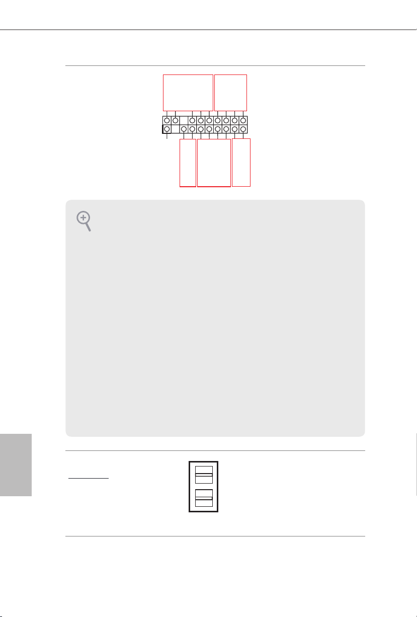
Embase panneau
1
A
B
auxiliaire
(AUX_PANEL1 à
18 broches )
(voir p.1, No. 30)
Cette embase prend en charge
plusieurs fonctions du panneau
SMB _Aler t
SMB _CLK
LAN 1_LIN K
+3V SB
GND
SMB _DATA
avant, dont le SMB du panneau
LED _PWR
LED _PWR
LAN 2_LIN K
avant, le voyant d'état Internet et
la broche d'intrusion châssis.
GND
+5V SB
CAS EOPEN
C
GND
LOC ATORBTN #
LOC ATORLED 1-
LOC ATORLED 1+
E
Sys tem F ault LED+
D
Sys tem F ault LED-
A. Broche de connexion SMBus du panneau avant (FPSMB à 6-1 broches)
Cette embase permet de connecter des équipements SMBus (System Management Bus). Elle peut être
utilisée pour la communication entre les équipements périphériques du système, qui ont des taux de
transmission plus lents, et les équipements de gestion de l'alimentation.
B. Voyant d’état Internet (LAN1_LED, LAN2_LED à 2 broches)
Ces deux embases à 2 broches vous permettent d'utiliser le câble du voyant Internet Gigabit pour
vous connecter au voyant d'état du LAN. Lorsque ce voyant clignote, cela signifie que l'Internet est
correctement connecté.
C. Broche d'intrusion châssis (CHASSIS à 2 broches)
Cette embase est prévue pour les châssis d'ordinateurs hôtes dotés d'un système de détection
d'intrusion châssis. En outre, elle doit également fonctionner avec des équipements de détection
externes, tel qu'un capteur de détection d'intrusion châssis ou un micro-contacteur. Lorsque cette
fonction est activée, si un mouvement d'un quelconque composant du châssis se produit, le capteur
le détecte immédiatement et envoie un signal à cette embase, et le système enregistre alors cet
événement d'intrusion châssis. Le paramètre par défaut est réglé sur la broche CASEOPEN et GND ;
cette fonction est désactivée.
D. LED de localisation (LOCATOR à 4 broches)
Cette embase est destinée au commutateur de localisation et à la LED du panneau avant.
E. LED de défaillance système (LOCATOR à 2 broches)
Cette embase est destinée à la LED de défaillance système.
Français
62
Connecteur Mini-SAS HD
Angle droit :
(SATA_0_3)
(voir p.1, No. 22)
SATA_0_3
Ce connecteur prend en charge
les câbles de données MiniSAS
vers SATA pour les périphériques
de stockage internes avec un
taux de transfert de données
jusqu'à 6,0 Go/s.

C621A WS
65 4321
NC
Dummy
IntA_PA_D+
IntA_PB_SSRX-
Embase USB 3.2 Gen1
(USB3_5_6 à 19 broches)
(voir p.1, No. 6)
Connecteurs du
ventilateur système
(FAN1 à 6 broches)
(FAN2 à 6 broches)
(FAN3 à 6 broches)
(FAN4 à 6 broches)
(FAN5 à 6 broches)
(Voir p.1, No. 3, 8, 13, 14,
19)
Embases USB 3.2 Gen2
de type C en face avant
(USB31_TC_1 à
20 broches)
(voir p.1, No. 23)
(USB31_TC_2 à
20 broches)
(voir p.1, No. 24)
1
IntA_PA_D-
GND
IntA_PA_SSTX+
IntA_PBA_SSTX+
GND
IntA_PB_D-
IntA_PB_D+
FAN_SPEED_CONTROL
SENSOR
IntA_PA_SSTX-
GND
IntA_PA_SSRX+
IntA_PA_SSRX-
IntA_PB_SSRX+
GND
IntA_PB_SSTX-
GND
FAN_VOLTAGE
FAN_SPEED
Vbus
En plus des quatre ports
USB 3.2 Gen1 par défaut sur le
panneau d'E/S, cette carte mère
est équipée d'une embase USB
3.2 Gen1. Cette embase USB 3.2
Gen1 peut supporter deux ports
USB 3.2 Gen1.
Vbus
Veuillez brancher les câbles du
ventilateur sur les connecteurs
du ventilateur, puis reliez le l
noir à la broche de mise à terre.
Tous les ventilateurs prennent
en charge le contrôleur de
ventilateur.
Cette carte mère comporte deux
embases USB 3.2 Gen2 de type
C en face avant. Ces embases
sont utilisées pour connecter
des modules USB 3.2 Gen2
pour des ports USB 3.2 Gen2
supplémentaires.
*2 embases USB de type C (USB31_
TC1/USB31_TC2) sont partagées avec 2
connecteurs SATA à 7 broches (SSATA_2/
SSATA_3) (en option par rapport à la
nomenclature).
Français
Connecteur USB 2.0
(USB_1)
(voir p.1, No. 34)
Il y a un port USB 2.0 vertical
sur cette carte mère.
63
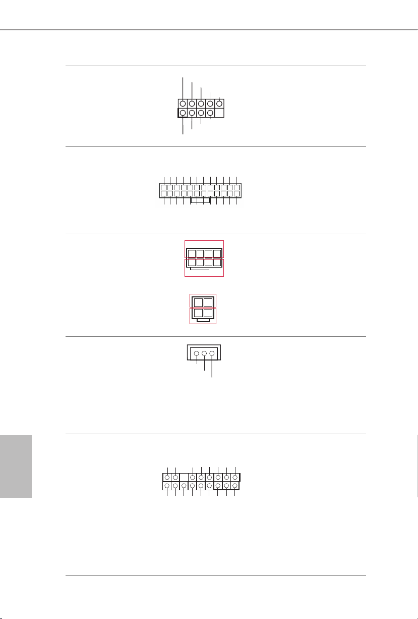
Embase USB 2.0
DUMMY
USB_PWR
USB_PWR
1
PWROK_PS
PSON#
4
8
1
5
12V
SMB _DA TA _MA I
#
+5
+12V
(USB_2_3 à 9 broches)
(voir p.1, No. 27)
P-
P+
GND
Il s’agit d’une embase sur cette
carte mère. Cette embase USB
2.0 peut prendre en charge deux
ports.
GND
P+
P-
Français
64
Connecteur
d’alimentation ATX
(ATXPWR1 à 24 broches)
(voir p.1, No. 4)
Connecteur
d’alimentation ATX 12V
(ATX12V1 à 8 broches)
(voir p.1, No. 5)
(ATX12V2 à 4 broches)
(voir p.1, No. 7)
Connecteur d'alimentation
SATA DOM
(SATAPWR1 à 3 broches)
(voir p.1, No. 15)
(SATAPWR2 à 3 broches)
(voir p.1, No. 12)
Embase TPM
(TPM1 à 17 broches)
(voir p.1, No. 36)
GND
3V
3V
5V
5VSB
GND
GND
12V
5V
Cette carte mère est dotée d’un
12V
3V
connecteur d’alimentation
ATX à 24 broches. Pour utiliser
121
une alimentation ATX à 20
13
3V
-12V
GND
GND
GND
GND
24
broches, veuillez eectuer les
5V5V5V
GND
N/A
branchements sur la Broche 1 et
la Broche 13.
GND
Cette carte mère ore un
connecteur d'alimentation ATX
12V à 8 broches et un autre à
4 broches.
GND
1
3
2
4
12V
Veuillez utiliser un câble
d'alimentation SATA pour
V
GND
raccorder ce connecteur
d'alimentation SATA et votre
disque dur SATA an d’alimenter
la carte mère, lorsque vous
utilisez le mode DC-IN sans
alimentation SATA.
Ce connecteur prend en charge
K
GND
LAD 0
LAD 3
+3V
+3V SB
D
GN
SER IRQ#
S_P WRD WN#
PCI RST #
N
GND
LAD 1
LAD 2
un module TPM (Trusted
LFR AME
PCI CL
Platform Module – Module de
1
plateforme sécurisée), qui permet
de sauvegarder clés, certicats
D
numériques, mots de passe et
GN
données en toute sécurité. Le
système TPM permet également
SMB _CL K_ MAI N
de renforcer la sécurité du
réseau, de protéger les identités
numériques et de préserver
l’intégrité de la plateforme.
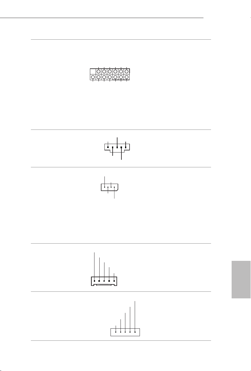
C621A WS
GND
ALERT
SMBCLK
IPMB_SDA
L
No Connect
BMC_SMB_PRESENT_1_N
BMC_SMBDATA7
1
+3V
P
Embase TPM-SPI
(TPM_BIOS_PH1 à
13 broches)
(voir p.1, No. 32)
Embase SMBus du bloc
d’alimentation
(PSU_SMB1 à 5 broches)
(voir p.1, No. 2)
Embase de bus de gestion
de plateforme intelligente
(IPMB1 à 4 broches)
(voir p.1, No. 43)
TPM_CS#
SPI_RST
SPI PIRQ
1
SMBDATA
GND
RSMRST#
GND
MOSI
SPI_CLK
IPMB_SC
MISO
X
SPI_WP
SPI_CS
+3.3V
SPI_HOLD
+3V
Ce connecteur prend en charge
le système Trusted Platform
Module (TPM) pour l'interface
SPI, qui peut stocker en toute
1
sécurité des clés, des certicats
numériques, des mots de passe
et des données. Le système TPM
permet également de renforcer
la sécurité du réseau, de protéger
les identités numériques et
de préserver l’intégrité de la
plateforme.
Le SMBus du bloc d’alimentation
surveille l'état de l'alimentation,
du ventilateur et de la
température du système.
Ce connecteur à 4 broches
est utilisé pour fournir une
connexion câblée à la carte de
base ou au panneau avant pour
les fonctions à valeur ajoutée
et les cartes d'extension tierces,
comme les cartes de gestion des
urgences, qui fournissent des
fonctions de gestion utilisant
l'IPMB.
Embase SMBus du
contrôleur de gestion de
la carte de base
(BMC_SMB_1 à
5 broches)
(voir p.1, No. 41)
Embase HP-SMBus
processeur
(CPU1_HSBP1 à
5 broches)
(voir p.1, No. 1)
Power
BMC_SMBCLK7
GND
CPU_HP_SCL
CPU_HP_SDA
0_HP_ALERT_L
GND
Cette embase est utilisée pour les
périphériques SM BUS.
Français
Cette embase est utilisée pour
la fonction de branchement à
chaud des disques durs sur le
fond de panier.
65

DOM Serial ATA3
DDCD#1
1
Connecteurs
(SATA_4)
(voir p.1, No. 18)
(SATA_5)
(voir p.1, No. 16)
SATA_5
SATA_4
Les connecteurs DOM SATA3
prennent en charge les deux
DOM SATA (Disk-On-Module)
et les câbles de données SATA
pour les périphériques de
stockage internes.
Français
Connecteurs Serial ATA3
Vertical:
(SATA_4)
(voir p.1, No. 18)
(SATA_5)
(voir p.1, No. 16)
Embase pour port série
(COM1 à 9 broches)
(voir p.1, No. 44)
Vider la mémoireCMOS
(CLRMOS1)
(voir p.1, No. 58)
RRTS#1
RRI#1
CCTS#1
SATA_5
SATA_4
TTXD1
GND
DDSR#1
DDTR#1
Ces deux connecteurs SATA3
prennent en charge les câbles
de données SATA pour les
périphériques internes de
stockage avec des taux de
transfert de données allant
jusqu'à 6,0 Go/s.
*2 embases USB de type C (USB31_
TC1/USB31_TC2) sont partagées avec 2
connecteurs SATA à 7 broches (SSATA_2/
SSATA_3) (en option par rapport à la
nomenclature).
Cette embase COM prend en
charge un module de port série.
1
RRXD1
Cela vous permet d'eacer les
données du CMOS. Pour vider
la CMOS, retirez la batterie de la
CMOS puis court-circuitez pour
vider la mémoire CMOS.
Embase de bouton
d'interruption non
masquable
(NMI_BTN2)
GND
CONTROL
Veuillez connecter un
périphérique NMI à cette
embase.
(voir p.1, No. 46)
66

C621A WS
TR1
LAN3_LINK
SCLOCK
GND
GND
H_VSENSEINPMAX_CPU1
Embase du capteur
thermique
(TR1 à 2 broches)
(voir p.1, No. 39)
Embase LED LAN avant
(FRONT_LED_LAN34 à
4 broches)
(voir p.1, No. 35)
Embase du haut-parleur
du châssis
(SPEAKER1 à 4 broches)
(voir p.1, No. 26)
Embases d'entrée/sortie
série à usage général
(SATA_SGPIO1 à
7 broches)
(voir p.1, No. 37)
(SSATA_SGPIO1 à
7 broches)
(voir p.1, No. 38)
1
1
LED_PWR
DUMMY
1
+5V
SLOAD
GND
1
SDATAOUT
LAN4_LINK
LED_PWR
SPEAKER
DUMMY
Veuillez connecter le câble du
capteur thermique à la broche
1-2 ou à la broche 2-3 et l'autre
extrémité au périphérique dont
vous souhaitez surveiller la
température.
Ce connecteur à 4 broches est
utilisé pour le voyant d'état du
réseau local LAN avant.
Veuillez brancher le haut-parleur
du châssis sur cette embase.
Ces embases prennent en charge
l'interface Serial Link pour les
connexions SATA embarquées.
Embase de conguration
PWM
(PWM_CFG1 à
3 broches)
(voir p.1, No. 11)
Embase VSENSE CPU
(CPU_VSENSE à
3 broches)
(voir p.1, No. 10)
1
1
SMB_DATA_VSB
SMB_CLK_VSB
GND
GND
Cette embase sert aux
congurations PWM.
Cette embase sert à détecter
CPU1 VSENSE.
Français
67

Virtual RAID sur CPU
GND
Embase
(RAID_1 à 4 broches)
(voir p.1, No. 28)
1
VROC RAID KEY
GND
+3VSB
Ce connecteur prend en charge
Intel® Virtual RAID sur CPU et
NVME/AHCI RAID sur CPU
PCIE.
Avec le lancement du produit Intel VROC,il existe trois modes de fonctionnement:
SKU Touche HW requise Fonctions principales
• Intercommunication uniquement
(pas de RAID)
Intercommunication Non nécessaire
• Gestion des LED
• Prise en charge du branchement à chaud
• Prise en charge RAID 0 des SSD Intel
Fultondale NVMe
Français
Standard VROCSTANMOD
Premium
VROCPREMMOD
• Fonctions SKU d'intercommunication
• RAID 0, 1, 10
• Fonctions SKU standard
• RAID 5
ISS
VROCISSDMOD
• Fermeture du trou d'écriture RAID 5
*Seuls les SSD Intel sont pris en charge.
*Pour plus de détails sur VROC, veuillez consulter les informations ocielles publiées par
Intel.
68

1.5 LED/commutateur d'identication de l'unité
Grâce au bouton UID, vous pouvez localiser le serveur sur lequel vous travaillez derrière un
rack de serveurs.
C621A WS
LED/commutateur
d'identication de l'unité
(UID1)
(voir p.6, No. 9)
Lorsque vous appuyez sur
le bouton UID situé sur le
panneau avant ou arrière, le
voyant LED bleu UID avant/
arrière s'allume. Appuyez de
nouveau sur le bouton UID
pour éteindre le voyant.
69
Français

1 Introduzione
Congratulazioni per l’acquisto della scheda madre C621A WS, una scheda madre adabile
prodotta secondo i severissimi controlli di qualità ASRock. La scheda madre ore eccellenti
prestazioni con un design robusto che si adatta all'impegno di ASRock di orire sempre
qualità e durata.
Dato che le speciche della scheda madre e del soware BIOS possono essere aggiornate, il
contenuto di questa documentazione sarà soggetto a variazioni senza preavviso. Nel caso di
eventuali modiche della presente documentazione, la versione aggiornata sarà disponibile sul
sito Web di ASRock senza ulteriore preavviso. Per il supporto tecnico correlato a questa scheda
madre, visitare il nostro sito Web per informazioni speciche relative al modello attualmente
in uso. È possibile trovare l'elenco di schede VGA più recenti e di supporto di CPU anche sul
sito Web di ASRock. Sito Web di ASRock http://www.asrock.com.
1.1 Contenuto della confezione
Scheda madre ASRock C621A WS (Form Factor ATX)
•
Guida all'installazione rapida di ASRock C621A WS
•
CD di supporto ASRock C621A WS
•
1 x modulo TPM-SPI
•
1 x supporto CPU non in tessuto (opzionale)
•
1 x cavo da Mini SAS HD a 4 * SATA (60 cm) (opzionale)
•
1 x cavo di alimentazione SATA (80 cm) (opzionale)
•
1 x cavo dati SATA3 (60 cm) (opzionale)
•
1 x mascherina metallica posteriore I/O
•
Italiano
70
In caso di elementi mancanti o danneggiati, contattare il rivenditore autorizzato.

1.2 Speciche
Piattaforma
CPU
Chipset
Memoria
Fattore di forma ATX
•
PCB a 12 layer
•
PCB 2oz rame
•
Processori scalabili Intel® Xeon® di terza generazione
•
Intel® Socket 4189 (Socket P+)
•
Digi Power design
•
7 Power Phase Design
•
Intel® C621A
•
Tecnologia di memoria a otto canali (1DPC)
•
8 x alloggi DIMM DDR4
•
Supporta DDR4 3200/2933/2666/2400/2133/1866 DDR4 RDIMM/
•
RDIMM-3DS/ LRDIMM/ LRDIMM-3DS/ Memoria persistente
Intel® Optane™ serie 200
Capacità max. della memoria di sistema: RDIMM: 64GB,
•
LRDIMM: 128GB, RDIMM-3DS/ LRDIMM-3DS: 256GB
C621A WS
Alloggio
d’espansione
Graca
LAN
4 x slot PCIe Gen4x16 (PCIE1/PCIE3/PCIE5/PCIE7)*
•
3 x slot PCIe Gen4x8 (PCIE2/PCIE4/PCIE6)*
•
* Se l’alloggio PCIE2 è occupato, l’alloggio PCIE3 sarà declassato a
modalità x8. Se l’alloggio PCIE4 è occupato, l’alloggio PCIE5 sarà
declassato a modalità x8. Se l’alloggio PCIE6 è occupato, l’alloggio
PCIE7 sarà declassato a modalità x8.
Controller BMC Aspeed® AST2500
•
Supporta D-Sub con una risoluzione max. no a 1920 x 1200 a
•
60 Hz
2 x LAN 10 Gigabit 100/1000/2500/5000/10000 Mb/s
(Intel® X710-AT2)
Supporto WOL (Wake-On-LAN)
•
Supporta protezione da fulmini/scariche elettrostatiche
•
Supporto Energy Ecient Ethernet 802.3az
•
Supporto PXE
•
Italiano
71

Italiano
Archiviazione
RAID
I/O pannello
posteriore
2 x LAN Gigabit 10/100/1000 Mb/s (Intel® I210)
Supporto WOL (Wake-On-LAN)
•
Supporta protezione da fulmini/scariche elettrostatiche
•
Supporto Energy Ecient Ethernet 802.3az
•
Supporto PXE
•
1 x IPMI dedicato (ASPEED AST2500)
Supporto iKVM and vMedia
•
2 x Connettori SATA3 6,0 Gb/s
•
1 x Connettore mini-SAS HD
•
1 x socket Ultra M.2 (M2_1, key M), supporta le modalità di tipo
•
2242/2280/22110 SATA3 6,0 Gb/s e PCIe Gen3x4 (32 Gb/s)*
1 x socket M.2 (M2_2, chiave M), supporta le modalità di tipo
•
2242/2280/22110 SATA3 6,0 Gb/s e PCIe Gen3x1 (8 Gb/s)*
* Supporta la tecnologia Intel® Optane
* Supporto di SSD NVMe come disco d’avvio
* Supporta kit ASRock U.2
Mendukung RAID 0, RAID 1, RAID 5 dan RAID 10 untuk
•
perangkat penyimpanan SATA
Supporta RAID 0, RAID 1, RAID 5 per dispositivi di archiviazione
•
M.2 NVMe
1 x interruttore UID con LED
•
1 x porta D-Sub
•
4 x porte USB 3.2 Gen1 (supporto protezione da scariche
•
elettrostatiche)
2 x RJ45 (10GbE), 2 x RJ45 (1GbE)
•
1 x RJ45 Porta LAN IPMI dedicata
•
TM
72
Connettore
1 x connettore SPI TPM
•
1 x connettore LPC TPM
•
1 x connettore porta COM
•
5 x connettore ventola di sistema (6 pin)
•
1 x connettore alimentazione ATX 24-pin (connettore
•
alimentazione ad alta densità)

1 x connettore alimentazione 12V 8-pin (connettore alimentazione
•
ad alta densità)
1 x connettore alimentazione 12V 4-pin (connettore alimentazione
•
ad alta densità)
1 x USB 2.0 verticale tipo A
•
1 x Connettore USB 2.0 (supporto di 2 porte USB 2.0) (supporto
•
protezione da scariche elettrostatiche)
1 x Header USB 3.2 Gen1 (supporto di 2 porte USB 3.2 Gen1)
•
(supporto protezione da scariche elettrostatiche)
2 x porte USB3.2 Gen2 (2 header tipo C)
•
2 x Connettori USB 3.2 Gen2 tipo C pannello anteriore (supporto
•
protezione da scariche elettrostatiche)
2 x Header SGPIO
•
1 x Connettore pannello ausiliare
•
1 x Connettore bus di gestione della piattaforma intelligente
•
1 x header connettore hot plug PCI Express del backplane
•
1 x Header SMBus
•
1 x Header PMbus
•
1 x connettore CPU HP-SMBus
•
1 x Header sensore termico
•
1 x RAID virtuale su connettore CPU
•
1 x LED Heartbeat BMC
•
1 x LED di alimentazione in standby
•
5 x LED guasto ventola
•
1 x header pulsante di interruzione non mascherabile
•
1 x cicalino
•
1 x Dr. Debug con LED
•
C621A WS
Funzionalità
BIOS
Hardware
Monitor
BIOS AMI UEFI Legal
•
Eventi di riattivazione conformi a ACPI 5.0
•
Supporto di SMBIOS 2.3
•
Sensore di temperatura: CPU, PCH, MB, Card Side
•
Tachimetro ventola: Tachimetro ventola anteriore, posteriore, CPU
•
Ventola silenziosa (regolazione automatica velocità in base alla
•
temperatura della CPU): Ventola CPU
Controllo velocità ventola: Ventola anteriore, posteriore, CPU
•
Monitoraggio tensione: CPU1_PVCCIN, PVDDQ_ABCD,
•
PVDDQ_EFGH, 1,05V_PCH, 1,8V_PCH, +BAT,
PVNN_PCH, 3,3V, 5V, 12V, 3,3VSB, 5VSB
Italiano
73

SO
Microso® Windows®
10 64-bit / 11 64-bit
•
Server 2016 (64 bit)
•
Server 2019 (64 bit)
•
Server 2022 (64 bit)
•
Linux®:
Red Hat Enterprise Linux Server 7.9 (64 bit) / 8.3 (64 bit)
•
CentOs 7.9 (64 bit) / 8.3 (64 bit)
•
SUSE Enterprise Linux Server 12 SP5 (64 bit) / 15 SP2 (64 bit)
•
Ubuntu 20.04.1 (64 bit) / 20.10 (64 bit)
•
Hypervisor:
VMWare® ESXi 6.7 U3 / vSphere 6.7 U3
•
VMWare® ESXi 7.0.U1c / vSphere 7.0.U1c
•
Hyper-V Winders Server 2016
•
Hyper-V Winders Server 2019
•
* Fare riferimento al nostro sito Web per l’elenco di supporto del sistema operativo più
recente.
FCC, CE
Certicazioni
* Per informazioni dettagliate sul prodotto, visitare il nostro sito Web: http://www.asrock.com
•
ErP/EuP Ready (è necessaria alimentazione ErP/EuP ready)
•
Italiano
74
Prestare attenzione al potenziale rischio previsto nella pratica di overclocking, inclusa la
regolazione delle impostazioni nel BIOS, l'applicazione di tecnologia di Untied Overclocking o
l'utilizzo di strumenti di overclocking di terze parti. L'overclocking può inuenzare la stabilità
del sistema o perno provocare danni ai componenti e ai dispositivi del sistema. Occorre
eseguirlo a proprio rischio e spese. Non ci riterremo responsabili per possibili danni provocati
da overclocking.
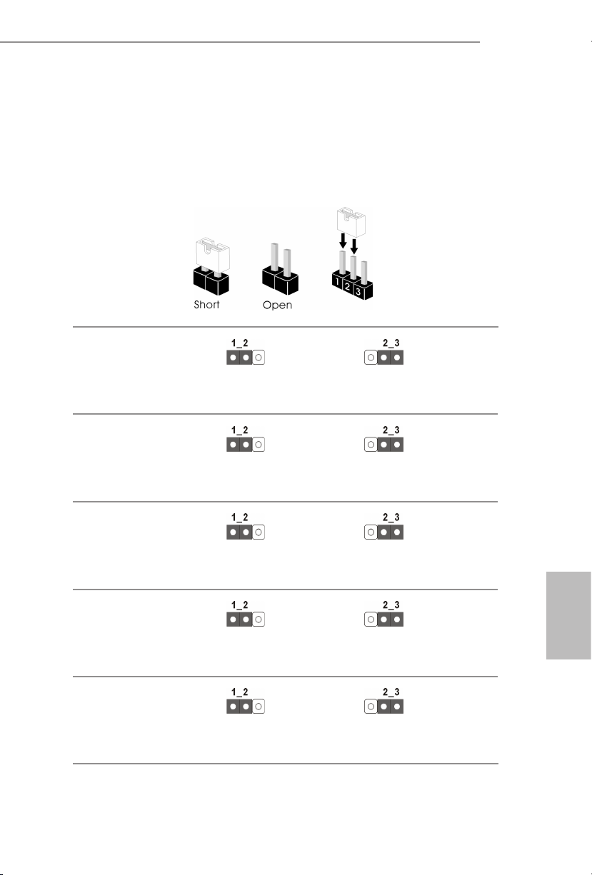
1.3 Impostazione jumper
L'illustrazione mostra in che modo vengono impostati i jumper. Quando il cappuccio del
jumper è posizionato sui pin, il jumper è "cortocircuitato". Se sui pin non è posizionato alcun
cappuccio del jumper, il jumper è "aperto". L'illustrazione mostra un jumper a 3 pin i cui pin1
e pin2 sono "cortocircuitati" quando un cappuccio del jumper è posizionato su questi 2 pin.
Jumper di selezione MiniSAS
HD SATA/PCIE
(MINISAS_1 a 3 pin)
(vedere pag. 1, n. 40)
Jumper modalità CPU PECI
(PECI1 a 3 pin)
(vedere pag. 1, n. 48)
SATA (predenito)
CPU PECI collegata a PCH
PCIE
CPU PECI collegata a BMC
(predenita)
C621A WS
Jumper di esclusione di
sicurezza
(SEC_OR1 a 3 pin)
(vedere pag. 1, n. 33)
Jumper recupero ME
(ME_RECOVERY1 a 3 pin)
(vedere pag. 1, n. 49)
Jumper di ripristino password
(PASSWORD_CLEAR a 3 pin)
(vedere pag. 1, n. 51)
Descrittore esclusione di
sicurezza
Modalità normale
(opzione predenita)
Modalità normale
(opzione predenita)
Nessuna esclusione
(opzione predenita)
Modalità recupero ME
Ripristino password
Italiano
75
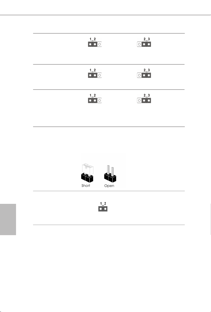
Jumper recupero BIOS
(BIOS_RECOVERY1 a 3 pin)
(vedere pag. 1, n. 45)
Jumper di selezione ESPI/LPC
(ESPI_LPC_SEL1 a 3 pin)
(vedere pag. 1, n. 54)
Jumper di condivisione ash
ESPI
(ESPI_SHARE a 3 pin)
(vedere pag. 1, n. 42)
L'illustrazione mostra in che modo vengono impostati i jumper. Quando il cappuccio del
jumper è posizionato sui pin, il jumper è "cortocircuitato". Se sui pin non è posizionato alcun
cappuccio del jumper, il jumper è "aperto".
Modalità normale
(opzione predenita)
ESPI (opzione predenita)
Condivisione ash ESPI
principale (impostazione
predenita)
Recupero BIOS
LPC
Condivisione ash ESPI
slave
Italiano
76
Jumper di esclusione swap
BIOS
(ESPI_MODE1)
(vedere pag. 1, n. 52)
2-pin Jumper
Aperto: Disabilita esclusione
(opzione predenita)
Cortocircuitato: Abilita esclusione
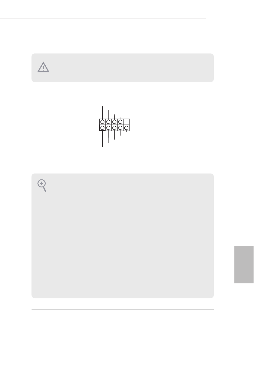
1.4 Header e connettori su scheda
Gli header e i connettori sulla scheda NON sono jumper. NON posizionare cappucci del jumper
su questi header e connettori. Il posizionamento di cappucci del jumper su header e connettori
provocherà danni permanenti alla scheda madre.
C621A WS
Header sul pannello del
sistema
(PANEL1 a 9 pin)
(vedere pag. 1, n. 29)
PWRBTN (interruttore di alimentazione):
collegare all'interruttore dell'alimentazione sul pannello anteriore dello chassis. È possibile congurare
il modo in cui spegnere il sistema utilizzando l'interruttore dell'alimentazione.
RESET (interruttore di reset):
collegare all'interruttore di reset sul pannello anteriore dello chassis. Premere l'interruttore di reset
per riavviare il computer se il computer si blocca e non riesce ad eseguire un normale riavvio.
PLED (LED alimentazione del sistema):
collegare all'indicatore di stato dell'alimentazione sul pannello anteriore dello chassis. Il LED è acceso
quando il sistema è in funzione. Il LED è spento quando il sistema si trova nello stato di sospensione
S4 o quando è spento (S5).
HDLED (LED di attività disco rigido):
collegare al LED di attività disco rigido sul pannello anteriore dello chassis. Il LED è acceso quando il
disco rigido sta leggendo o scrivendo dati.
Il design del pannello anteriore può cambiare a seconda dello chassis. Un modulo di pannello
anteriore è composto principalmente da interruttore di alimentazione, interruttore di reset, LED
di alimentazione, LED di attività disco rigido, altoparlante, ecc. Quando si collega il modulo
del pannello anteriore dello chassis a questo header, accertarsi che le assegnazioni del lo e le
assegnazioni del pin corrispondano correttamente.
1
PLED+
PLED-
HDLED-
HDLED+
PWRBTN#
GND
GND
RESET#
GND
Collegare l'interruttore
dell'alimentazione, l'interruttore
di reset e l'indicatore dello
stato del sistema sullo chassis
su questo header secondo
l’assegnazione pin. Annotare
in particolare i pin positivi e
negativi prima di collegare i
cavi.
Italiano
77

Connettore pannello
1
A
B
ausiliare
(AUX_PANEL1 a 18 pin)
(vedere pag. 1, n. 30)
A. Pin di collegamento SMBus del pannello frontale (6-1 pin FPSMB)
Questo header consente di collegare apparecchiature SMBus (System Management Bus). Può essere
utilizzato per la comunicazione tra le apparecchiature periferiche del sistema dotate di velocità di
trasmissione inferiori e le apparecchiature di gestione dell'alimentazione.
B. Indicatore di stato di internet (LAN1_LED a 2 pin, LAN2_LED)
Questi due header a 2 pin consentono di utilizzare il cavo dell'indicatore Internet Gigabit per
connettersi all'indicatore di stato LAN. Quando questo indicatore lampeggia, signica che internet è
connesso correttamente.
C. Perno di intrusione nello chassis (CHASSIS a 2 pin)
Questo header serve per lo chassis del computer host con design di rilevamento delle intrusioni
dello chassis. Inoltre, deve funzionare anche con apparecchiature di rilevamento esterne, come
un sensore di rilevamento delle intrusioni dello chassis o un microinterruttore. Quando questa
funzione è attivata, se si verica un movimento di un componente dello chassis, il sensore lo rileverà
immediatamente e invierà un segnale a questo header, quindi il sistema registrerà questo evento di
intrusione nello chassis. L'impostazione predenita è impostata sui pin CASEOPEN e GND; questa
funzione è disattivata.
Questo connettore supporta più
funzioni sul pannello anteriore,
SMB _Aler t
SMB _CLK
LAN 1_LIN K
+3V SB
GND
SMB _DATA
tra cui SMB del pannello
LED _PWR
LED _PWR
LAN 2_LIN K
anteriore, indicatore di stato
Internet e pin di intrusione
dello chassis.
GND
+5V SB
CAS EOPEN
C
GND
LOC ATORBTN #
LOC ATORLED 1-
LOC ATORLED 1+
E
Sys tem F ault LED+
D
Sys tem F ault LED-
Italiano
78
D. LED di localizzazione (LOCALIZZATORE a 4 pin)
Questo header serve per l'interruttore di localizzazione e il LED sul pannello anteriore.
E. LED di errore del sistema (LOCALIZZATORE a 2 pin)
Questo header serve per il LED di errore sul sistema.
Connettore HD Mini-SAS
Angolo destro:
(SATA_0_3)
(vedere pag. 1, n. 22)
SATA_0_3
Questo connettore supporta i
cavi dati da MiniSAS a SATA
per dispositivi di archiviazione
interna, con una velocità di
trasferimento dati no a
6,0 Gb/s.
C621A WS
AN_SPEED_CONTROL
65 4321
NC
Dummy
IntA_PA_D+
IntA_PB_SSRX-
Header USB 3.2 Gen1
(USB3_5_6 a 19 pin)
(vedere pag. 1, n. 6)
Connettori ventola di
sistema
(FAN1 a 6 pin)
(FAN2 a 6 pin)
(FAN3 a 6 pin)
(FAN4 a 6 pin)
(FAN5 a 6 pin)
(vedi p.1, n. 3, 8, 13, 14,
19)
Connettori USB 3.2 Gen2
tipo C pannello anteriore
(USB31_TC_1 a 20 pin)
(vedere pag. 1, n. 23)
(USB31_TC_2 a 20 pin)
(vedere pag. 1, n. 24)
1
IntA_PA_D-
GND
IntA_PA_SSTX+
GND
IntA_PB_D-
IntA_PB_D+
SENSOR
IntA_PA_SSTX-
GND
IntA_PA_SSRX+
IntA_PA_SSRX-
IntA_PB_SSRX+
GND
IntA_PB_SSTX-
IntA_PBA_SSTX+
GND
FAN_VOLTAGE
FAN_SPEED
F
Vbus
Oltre alle quattro porte USB 3.2
Gen1. predenite sul pannello
I/O, su questa scheda madre è
presente un connettore USB 3.2
Gen1. Questo connettore USB
3.2 Gen1 può supportare due
porte USB 3.2 Gen1.
Vbus
Collegare i cavi della ventola
ai connettori della ventola e
far corrispondere il lo nero
al pin di terra. Tutti le ventole
supportano Fan Control.
Sono presenti due connettori
USB 3.2 Gen2 tipo C pannello
anteriore su questa scheda
madre. Questi connettori
servono per il collegamento di
moduli USB 3.2 Gen2 per porte
USB 3.2 Gen2 supplementari.
*2 connettori USB tipo C (USB31_
TC1/USB31_TC2) sono condivisi con
2 connettori SATA a 7 pin (SSATA_2/
SSATA_3) (opzione BOM).
Italiano
Connettore USB 2.0
(USB_1)
(vedere pag. 1, n. 34)
È presente una porta USB 2.0
verticale su questa scheda
madre.
79

Connettore USB 2.0
DUMMY
USB_PWR
USB_PWR
1
PWROK_PS
PSON#
SMB _DA TA _MA I
8
1
5
12V
+5
+12V
(USB_2_3 a 9 pin)
(vedere pag. 1, n. 27)
P-
P+
GND
Su questa scheda madre è
presente un connettore.
Questo connettore USB 2.0
può supportare due porte.
GND
P+
P-
Italiano
80
Connettore di
alimentazione ATX
(ATXPWR1 a 24 pin)
(vedere pag. 1, n. 4)
Connettore di alimentazione
ATX da 12 V
(ATX12V1 a 8 pin)
(vedere pag. 1, n. 5)
(ATX12V2 a 4 pin)
(vedere pag. 1, n. 7)
Connettore di alimentazione
SATA DOM
(3-pin SATAPWR1)
(vedere pag. 1, n. 15)
(SATAPWR2 a 3 pin)
(vedere pag. 1, n. 12)
Header TPM
(TPM1 a 17 pin)
(vedere pag. 1, n. 36)
GND
3V
3V
5V
5VSB
GND
GND
12V
5V
Questa scheda madre è
12V
3V
dotata di un connettore di
121
alimentazione ATX a 24 pin.
Per utilizzare un'alimentazione
13
3V
-12V
GND
GND
GND
GND
24
ATX a 20 pin, collegarla lungo
5V5V5V
GND
N/A
il pin 1 e il pin 13.
GND
4
Questa scheda madre è
dotata di un connettore di
alimentazione ATX da 12 V a
8 pin e uno a 4 pin.
GND
1
3
2
4
12V
Utilizzare un cavo di
alimentazione SATA per
V
GND
collegare questo connettore di
alimentazione SATA e l'HDD
SATA per erogare alimentazione
dalla scheda madre, quando
si utilizza la modalità DC-IN
senza alimentazione SATA.
Questo connettore supporta
K
GND
LAD 0
+3V SB
D
GN
GND
SER IRQ#
S_P WRD WN#
LFR AME #
LAD 3
+3V
PCI RST #
N
LAD 1
LAD 2
il sistema Trusted Platform
PCI CL
Module (TPM), che può
1
archiviare in modo sicuro
chiavi, certicati digitali,
D
password e dati. Un sistema
GN
TPM permette anche di
potenziare la sicurezza della
SMB _CL K_ MAI N
rete, di proteggere identità
digitali e di garantire l'integrità
della piattaforma.

C621A WS
ALERT
SMBCLK
IPMB_SDA
L
No Connect
BMC_SMB_PRESENT_1_N
BMC_SMBDATA7
1
+3V
P
Header TPM-SPI
(TPM_BIOS_PH1 a
13 pin)
(vedere pag. 1, n. 32)
Header SMBus PSU
(PSU_SMB1 a 5 pin)
(vedere pag. 1, n. 2)
Connettore bus di
gestione della piattaforma
intelligente
(IPMB1 a 4 pin)
(vedere pag. 1, n. 43)
TPM_CS#
SPI_RST
SPI PIRQ
1
SMBDATA
GND
RSMRST#
GND
MOSI
SPI_CLK
IPMB_SC
MISO
X
GND
SPI_WP
SPI_CS
+3.3V
SPI_HOLD
+3V
Questo connettore supporta
il sistema Trusted Platform
Module (TPM) per interfaccia
1
SPI, che può archiviare in
modo sicuro chiavi, certicati
digitali, password e dati. Un
sistema TPM permette anche
di potenziare la sicurezza della
rete, di proteggere identità
digitali e di garantire l'integrità
della piattaforma.
PSU SMBus monitora lo stato
dell'alimentatore, della ventola
e della temperatura del sistema.
Questo connettore a 4 pin serve
a fornire una scheda madre
cablata o una connessione
al pannello anteriore per
funzionalità a valore aggiunto e
schede aggiuntive di terze parti,
come le schede di gestione delle
emergenze, che forniscono
funzionalità di gestione tramite
IPMB.
Connettore SMBus del
controller di gestione della
scheda madre
(BMC_SMB_1 a 5 pin)
(vedere pag. 1, n. 41)
Connettore CPU HPSMBus
(CPU1_HSBP1 a 5 pin)
(vedere pag. 1, n. 1)
Power
BMC_SMBCLK7
GND
CPU_HP_SCL
CPU_HP_SDA
0_HP_ALERT_L
GND
Il connettore serve per i
dispositivi SM BUS.
Italiano
Questo connettore serve per la
funzione hot plug degli HDD
sul backplane.
81

ATA3 DOM seriale
RRXD1
1
Connettori
(SATA_4)
(vedere pag. 1, n. 18)
(SATA_5)
(vedere pag. 1, n. 16)
SATA_5
SATA_4
I connettori SATA3 DOM
supportano entrambi i SATA
DOM (Disk-On-Module) e
cavi dati SATA per dispositivi
di archiviazione interni.
Italiano
Connettori Serial ATA3
Verticale:
(SATA_4)
(vedere pag. 1, n. 18)
(SATA_5)
(vedere pag. 1, n. 16)
Header porta seriale
(COM1 a 9 pin)
(vedere pag. 1, n. 44)
Pad Clear CMOS
(CLRMOS1)
(vedere pag. 1, n. 58)
Header pulsante di
interruzione non
mascherabile
(NMI_BTN2)
(vedere pag. 1, n. 46)
SATA_5
SATA_4
TTXD1
GND
RRTS#1
RRI#1
CCTS#1
DDSR#1
DDTR#1
GND
CONTROL
DDCD#1
Questi due connettori SATA3
supportano i cavi dati SATA
per dispositivi di archiviazione
interna, con una velocità di
trasferimento dati no a
6,0 Gb/s.
*2 connettori USB tipo C (USB31_
TC1/USB31_TC2) sono condivisi con
2 connettori SATA a 7 pin (SSATA_2/
SSATA_3) (opzione BOM).
Questo header COM supporta
un modulo di porta seriale.
1
Permette si azzerare i dati nella
CMOS. Per calcellare la CMOS,
estrarre la batteria CMOS e
cortocircuitare i pad Clear
CMOS.
Collegare un dispositivo NMI a
questo header.
82

C621A WS
1
TR1
GND
1
LAN4_LINK
LAN3_LINK
1
DUMMY
SPEAKER
SCLOCK
GND
SDA
GND
B
1
H_VSENSEINPMAX_CPU1
1
Header sensore termico
(TR1 a 2 pin)
(vedere pag. 1, n. 39)
Header LED LAN
anteriore
(FRONT_LED_LAN34 a
4 pin)
(vedere pag. 1, n. 35)
Header altoparlante
chassis
(SPEAKER1 a 4 pin)
(vedere pag. 1, n. 26)
Connettori input/output
generici seriali
(7-pin SATA_SGPIO1)
(vedere pag. 1, n. 37)
(7-pin SSATA_SGPIO1)
(vedere pag. 1, n. 38)
LED_PWR
+5V
GND
1
TAOUT
LED_PWR
DUMMY
SLOAD
Collegare il cavo del sensore
termico al pin 1-2 o al pin 2-3
e l'altra estremità al dispositivo
di cui si desidera monitorare la
temperatura.
Questo connettore a 4 pin viene
utilizzato per l'indicatore di
stato LAN anteriore.
Collegare l'altoparlante dello
chassis a questo header.
I connettori supportano
l'interfaccia di collegamento
seriale per collegamenti SATA
integrati.
Header congurazione
PWM
(PWM_CFG1 a 3 pin)
(vedere pag. 1, n. 11)
Header CPU VSENSE
(CPU_VSENSE a 3 pin)
(vedere pag. 1, n. 10)
SMB_DATA_VSB
SMB_CLK_VS
GND
GND
Questo header serve per le
congurazioni PWM.
Questo header serve a rilevare
CPU1 VSENSE.
Italiano
83

RAID virtuale su CPU
GND
Connettore
(RAID_1 a 4 pin)
(vedere pag. 1, n. 28)
1
VROC RAID KEY
GND
+3VSB
Questo connettore supporta
RAID virtuale Intel® su CPU e
RAID NVME/AHCI su PCIE
CPU.
Con l'introduzione del prodotto Intel VROC, ci sono tre modalità di funzionamento:
SKU
Tasto hardware
richiesto
Caratteristiche principali
• Solo Pass-through (no RAID)
• Gestione LED
Pass-through Non necessario
• Supporto collegamento a caldo
• Supporto RAID 0 per SSD Intel Fultondale
NVMe
Italiano
Standard VROCSTANMOD
Premium
VROCPREMMOD
• Caratteristiche SKU Pass-through
• RAID 0, 1, 10
• Caratteristiche SKU standard
• RAID 5
ISS
VROCISSDMOD
• Chiusura foro scrittura RAID 5
* Solo SSD Intel sono supportati.
* Per ulteriori dettagli su VROC, fare riferimento alle informazioni uciali fornite da Intel.
84

1.5 LED/Interruttore a scopo di identicazione dell’unità
Con il pulsante UID, è possibile individuare il server su cui si sta lavorando da dietro un rack
di server.
C621A WS
LED/Interruttore a scopo
di identicazione dell’unità
(UID1)
(vedere pag. 6, n. 9)
Quando si preme il pulsante
UID sul pannello anteriore o
posteriore, l'indicatore LED
blu UID anteriore/posteriore
si accende. Premere di nuovo
il pulsante UID per spegnere
l'indicatore.
85
Italiano

Español
1 Introducción
Gracias por adquirir la placa base ASRock C621A WS, una placa base fiable fabricada
siguiendo el sistemáticamente estricto control de calidad de ASRock. Ofrece un rendimiento
excelente con un diseño resistente de acuerdo con el compromiso de calidad y resistencia de
ASRock.
Ya que las especificaciones de la placa base y el software de la BIOS podrán ser actualizados, el
contenido que aparece en esta documentación estará sujeto a modificaciones sin previo aviso.
Si esta documentación sufre alguna modificación, la versión actualizada estará disponible en
el sitio web de ASRock sin previo aviso. Si necesita asistencia técnica relacionada con esta placa
base, visite nuestro sitio web para obtener información específica sobre el modelo que esté
utilizando. Podrá encontrar las últimas tarjetas VGA, así como la lista de compatibilidad de la
CPU, en el sitio web de ASRock. Sitio web de ASRock http://www.asrock.com.
1.1 Contenido del paquete
Placa base ASRock C621A WS (factor de forma ATX)
•
Guía de instalación rápida de ASRock C621A WS
•
CD de soporte de ASRock C621A WS
•
1 x módulo TPM-SPI
•
1 x Portador de CPU sin tela (opcional)
•
1 x Cable Mini-SAS HD a 4*SATA (60cm) (opcional)
•
1 x Cable de alimentación SATA (80cm) (opcional)
•
1 x Cable de datos SATA3 (60 cm) (opcional)
•
1 x escudo panel E/S
•
86
Si alguno de estos artículos falta o está dañado, póngase en contacto son el distribuidor autorizado.

1.2 Especicaciones
Factor de forma ATX
Plataforma
CPU
Conjunto de
chips
Memoria
•
Circuito impreso (PCB) de 12 capas
•
Circuito impreso (PCB) de 2 oz de cobre
•
Procesadores escalables Intel® Xeon® de tercera generación
•
Intel® Socket 4189 (Socket P+)
•
Digi Power design
•
Diseño de 7 fases de alimentación
•
Intel® C621A
•
Tecnología de memoria de ocho canales (1DPC)
•
8 x ranuras DIMM DDR4
•
Admite DDR4 3200/2933/2666/2400/2133/1866 DDR4 RDIMM/
•
RDIMM-3DS/LRDIMM/LRDIMM-3DS/Intel® Optane™ Persistent
Memory 200 Series
Capacidad máxima de memoria del sistema: RDIMM: 64GB,
•
LRDIMM: 128GB, RDIMM-3DS/LRDIMM-3DS: 256GB
C621A WS
Ranura de
expansión
Grácos
LAN
4 ranuras PCIe Gen4x16 (PCIE1/PCIE3/PCIE5/PCIE7)*
•
3 ranuras PCIe Gen4x8 (PCIE2/PCIE4/PCIE6)*
•
* Si PCIE2 está ocupado, PCIE3 se degradará al modo x8. Si PCIE4
está ocupado, PCIE5 se degradará al modo x8. Si PCIE6 está ocupado,
PCIE7 se degradará al modo x8.
Controlador Aspeed® AST2500 BMC
•
Admite D-Sub con una resolución máxima de 1920x1200 a 60 Hz
•
2 x 10 Gigabit LAN 100/1000/2500/5000/10000 Mb/s
(Intel® X710-AT2)
Admite la función Reactivación de LAN
•
Admite protección contra rayos y descargas electrostáticas (ESD)
•
Admite Ethernet 802.3az de eciencia energética
•
Admite PXE
•
Español
87

Almacenamiento
RAID
2 x Gigabit LAN 10/100/1000 Mb/s (Intel® I210):
Admite la función Reactivación de LAN
•
Admite protección contra rayos y descargas electrostáticas (ESD)
•
Admite Ethernet 802.3az de eciencia energética
•
Admite PXE
•
1 x IPMI dedicado (ASPEED AST2500)
Admite iKVM and vMedia
•
2 x Conectores SATA3 de 6,0 Gb/s
•
1 x Conector mini-SAS HD
•
1 x Zócalo Ultra M.2 (M2_1, Clave M), compatible con los modos
•
de tipo 2242/2280/22110 SATA3 6,0 Gb/s y PCIe Gen3x4
(32 Gb/s)*
1 x Zócalo M.2 (M2_2, Clave M), compatible con los modos de tipo
•
2242/2280/22110 SATA3 6,0 Gb/s y PCIe Gen3x1 (8 Gb/s)*
* Compatible con la tecnología OptaneTM de Intel®
* Admite unidad de estado sólido de NVMe como disco de arranque
* Admite el kit U.2 de ASRock
Admite RAID 0, RAID 1, RAID 5 y RAID 10 para dispositivos de
•
almacenamiento SATA
Admite RAID 0, RAID 1, RAID 5 para dispositivos de almacenam-
•
iento M.2 NVMe
Español
88
E/S en panel
posterior
Conector
1 x Interruptor UID con LED
•
1 x Puerto D-Sub
•
4 x Puertos USB 3.2 Gen1 (admite protección contra descargas
•
electrostáticas)
2 x RJ45 (10 GbE), 2 x RJ45 (1 GbE)
•
1 Puerto LAN IPMI dedicado RJ45
•
1 x Conector SPI TPM
•
1 x Encabezado LPC TPM
•
1 x Base de conexiones de puerto COM
•
5 x Conectores de ventilador del sistema (6 contactos)
•
1 x Conector de alimentación de 24 contactos y ATX (conector de
•
alimentación de alta densidad)

1 Conector de alimentación de 8 contactos y 12 V (conector de
•
alimentación de alta densidad)
1 Conector de alimentación de 4 contactos y 12 V (conector de
•
alimentación de alta densidad)
1 USB 2.0 vertical de tipo A
•
1 x Base de conexiones USB 2.0 (admite 2 puertos USB 2.0)
•
(admite protección contra descargas electrostáticas)
1 x base de conexiones USB 3.2 Gen1 (admite 2 puertos USB 3.2
•
Gen1) (Admite protección contra descargas electrostáticas)
2 x Puertos USB3.2 Gen2 (2 encabezados Tipo C)
•
2 x Base de conexiones Tipo C USB 3.2 Gen2 en el panel frontal
•
(admite protección ESD)
2 x Bases de conexiones SGPIO
•
1 x Base de conexiones en el panel auxiliar
•
1 x Base de conexiones de bus de administración de plataforma
•
inteligente
1 x Encabezado de conector de conexión en caliente PCI Express de
•
plano posterior
1 x Base de conexiones SMBus
•
1 x Base de conexiones PMBus
•
1 x Conector HP-SMBus de CPU
•
1 x Base de conexiones de sensor térmico
•
1 x RAID virtual en base de conexiones de CPU
•
1 x LED de latido BMC
•
1 x LED de encendido en espera
•
5 x LED de error de ventilador
•
1 x Base de conexiones del botón de interrupción no enmascarable
•
1 x Zumbador
•
1 x Dr. Debug con indicador LED
•
C621A WS
Función de la
BIOS
Monitor de
hardware
BIOS legal UEFI AMI
•
Eventos de reactivación compatibles con ACPI 5.0
•
Admite SMBIOS 2.3
•
Detección de temperatura: CPU, PCH, MB, lado de la tarjeta
•
Tacómetro del ventilador: Tacómetro del ventilador delantero,
•
trasero y de la CPU
Ventilador silencioso (ajuste automático de la velocidad del
•
ventilador del chasis por temperatura de la CPU): Ventilador de la
CPU
Control de varias velocidades del ventilador: Ventilador delantero,
•
trasero y de la CPU
Control del voltaje: CPU1_PVCCIN, PVDDQ_ABCD, PVDDQ_
•
EFGH, 1,05V_PCH, 1,8V_PCH, +BAT, PVNN_PCH, 3,3V, 5V,
12V, 3,3VSB, 5VSB
Español
89

SO
Microso® Windows®
10 64-bit / 11 64-bit
•
Server 2016 (64 bit)
•
Server 2019 (64 bit)
•
Server 2022 (64 bit)
•
Linux®:
Red Hat Enterprise Linux Server 7.9 (64 bit) / 8.3 (64 bit)
•
CentOs 7.9 (64 bit) / 8.3 (64 bit)
•
SUSE Enterprise Linux Server 12 SP5 (64 bit) / 15 SP2 (64 bit)
•
Ubuntu 20.04.1 (64 bit) / 20.10 (64 bit)
•
Hypervisor:
VMWare® ESXi 6.7 U3 / vSphere 6.7 U3
•
VMWare® ESXi 7.0.U1c / vSphere 7.0.U1c
•
Hyper-V Winders Server 2016
•
Hyper-V Winders Server 2019
•
* Consulte nuestro sitio web para obtener la lista de compatibilidad con el sistema
operativo más reciente.
FCC y CE
Certicaciones
•
Preparado para ErP/EuP (se necesita una fuente de alimentación
•
preparada para ErP/EuP)
* Para obtener información detallada del producto, visite nuestro sitio Web: http://www.asrock.com
Español
90
Tenga en cuenta que hay un cierto riesgo implícito en las operaciones de overclocking,
incluido el ajuste de la BIOS, aplicando la tecnología de overclocking liberada o utilizando las
herramientas de overclocking de otros fabricantes. El overclocking puede afectar a la estabilidad
del sistema e, incluso, dañar los componentes y dispositivos del sistema. Esta operación se debe
realizar bajo su propia responsabilidad y usted debe asumir los costos. No asumimos ninguna
responsabilidad por los posibles daños causados por el overclocking.
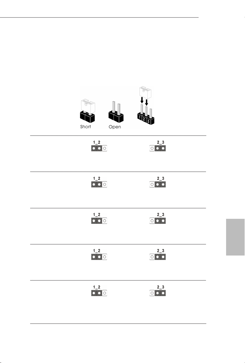
1.3 Instalación de los puentes
La instalación muestra cómo deben instalarse los puentes. Cuando la tapa de puente se coloca
en los contactos, el puente queda “Corto”. Si no coloca la tapa de puente en los contactos, el
puente queda “Abierto”. La ilustración muestra un puente de 3 contactos cuyo contacto 1 y
contacto 2 son “Cortos” cuando se coloca una tapa de puente en estos 2 contactos.
Puentes de selección MiniSAS
HD SATA/PCIE
(MINISAS_1 de 3 contactos)
(consulte la pág. 1, nº 40)
Puente de modo PECI CPU
(PECI1 de 3 contactos)
(consulte la pág. 1, nº 48)
SATA (predeterminado)
CPU PECI conectado a PCH
PCIE
CPU PECI conectado a BMC
(predeterminado)
C621A WS
Puente de anulación de
seguridad
(SEC_OR1 de 3 contactos)
(consulte la pág. 1, nº 33)
Puente de recuperación ME
(ME_RECOVERY1 de
3 contactos)
(consulte la pág. 1, nº 49)
Puente de restablecimiento
de contraseña
(PASSWORD_CLEAR de
3 contactos)
(consulte la pág. 1, nº 51)
Anulación de seguridad del
descriptor
Modo Normal
(predeterminado)
Modo Normal
(predeterminado)
No anular (predeterminado)
Español
Modo de recuperación ME
Borrar contraseña
91
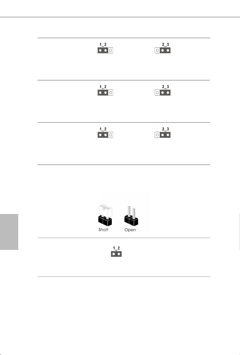
Puente de recuperación del
BIOS
(BIOS_RECOVERY1 de
3 contactos)
(consulte la pág. 1, nº 45)
Puente de selección
ESPI/LPC
(ESPI_LPC_SEL1 de
3 contactos)
(consulte la pág. 1, nº 54)
Puente de uso compartido
de ash ESPI
(ESPI_SHARE de
3 contactos)
(consulte la pág. 1, nº 42)
La instalación muestra cómo deben instalarse los puentes. Cuando la tapa de puente se
coloca en los contactos, el puente queda “Corto”. Si no coloca la tapa de puente en los
contactos, el puente queda “Abierto”.
Modo Normal
(predeterminado)
ESPI (predeterminado)
Uso compartido de
ash ESPI maestro
(predeterminado)
Recuperar el BIOS
LPC
Uso compartido de ash
ESPI esclavo
Español
92
Puente de anulación de
intercambio de BIOS
(ESPI_MODE1)
(consulte la pág. 1, nº 52)
2-pin Jumper
Abierto: Deshabilitar anulación
(predeterminado)
Corto: Habilitar anulación
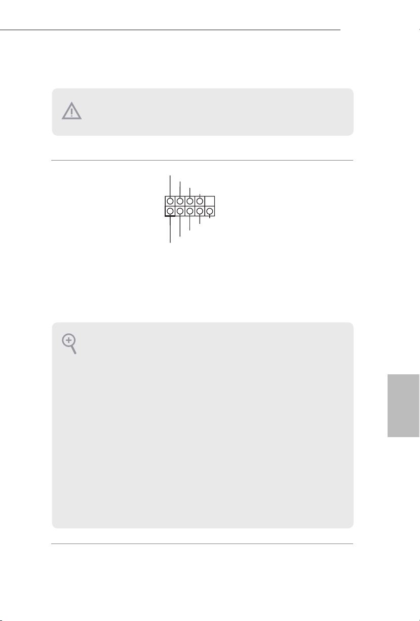
1.4 Conectores y cabezales incorporados
1
Los cabezales y conectores incorporados NO son puentes. NO coloque tapas de puente sobre estos
cabezales y conectores. Si coloca tapas de puente sobre los cabezales y conectores dañará de forma
permanente la placa base.
C621A WS
Cabezal del panel del
sistema
(PANEL1 de 9 contactos)
(consulte la pág. 1, nº 29)
PWRBTN (Interruptor de alimentación):
Conéctelo al interruptor de alimentación del panel frontal del chasis. Deberá configurar la forma en
la que su sistema se apagará mediante el interruptor de alimentación.
RESET (Interruptor de reseteo):
Conéctelo al interruptor de reseteo del panel frontal del chasis. Pulse el interruptor de reseteo para
resetear el ordenador si éste está bloqueado y no se puede reiniciar de forma normal.
PLED (Indicador LED de la alimentación del sistema):
Conéctelo al indicador de estado de la alimentación del panel frontal del chasis. El indicador LED
permanece encendido cuando el sistema está funcionando. El indicador LED se apaga cuando el
sistema se encuentra en estado de suspensión S4 o está apagado (S5).
HDLED (Indicador LED de actividad en el disco duro):
Conéctelo al indicador LED de actividad en el disco duro del panel frontal del chasis. El indicador
LED permanece encendido cuando el disco duro está leyendo o escribiendo datos.
El diseño del panel frontal puede ser diferente dependiendo del chasis. Un módulo de panel frontal
consta principalmente de: interruptor de alimentación, interruptor de reseteo, indicador LED de
alimentación, indicador LED de actividad en el disco duro, altavoz, etc. Cuando conecte su módulo
del panel frontal del chasis a este cabezal, asegúrese de que las asignaciones de los cables y los
contactos coinciden correctamente.
PLED+
PLED-
HDLED-
HDLED+
PWRBTN#
GND
GND
RESET#
GND
Conecte el interruptor de
alimentación, restablezca el
interruptor y el indicador del
estado del sistema del chasis
a los valores de este cabezal,
según los valores asignados a
los contactos como se indica a
continuación. Especialmente,
cerciórese de cuáles son los
contactos positivos y los
negativos antes de conectar los
cables.
Español
93

Español
1
A
B
Base de conexiones del
panel auxiliar
(AUX_PANEL1 de
18 contactos)
(consulte la pág. 1, nº 30)
A. Conector de conexión SMBus del panel frontal (FPSMB de 6-1 contactos)
Esta base de conexiones le permite conectar equipos SMBus (System Management Bus, es decir, Bus
de administración del sistema). Se puede utilizar para la comunicación entre equipos periféricos del
sistema, que tiene velocidades de transmisión más lentas, y equipos de administración de energía.
B. Indicador de estado de Internet (LAN1_LED de 2 contactos, LAN2_LED)
Estas dos bases de conexiones de 2 contactos le permiten usar el cable indicador de Internet Gigabit
para conectarse al indicador de estado de la LAN. Cuando este indicador parpadea, significa que la
red Internet está conectada correctamente.
C. Contacto de intrusión del chasis (CHASIS de 2 contactos)
Esta base de conexiones se proporciona para el chasis del equipo principal con diseños de detección
de intrusión del chasis. Además, también debe funcionar con equipos de detección externos, como un
sensor de detección de intrusión del chasis o un microinterruptor. Cuando se activa esta función, si
se produce algún movimiento de un componente del chasis, el sensor lo detectará inmediatamente y
enviará una señal a esta base de conexiones, y el sistema registrará este evento de intrusión del chasis.
La configuración predeterminada se establece en el contacto CASEOPEN y GND; esta función está
desactivada.
D. LED de localización (LOCALIZADOR de 4 contactos)
Esta base de conexiones es para el interruptor del localizador y el LED del panel frontal.
Esta base de conexiones admite
varias funciones en el panel
SMB _Aler t
SMB _CLK
LAN 1_LIN K
LED _PWR
+3V SB
GND
SMB _DATA
frontal, incluido el SMB del
LED _PWR
LAN 2_LIN K
panel frontal, el indicador de
estado de Internet y el pin de
intrusión del chasis.
GND
+5V SB
CAS EOPEN
C
GND
LOC ATORBTN #
LOC ATORLED 1-
LOC ATORLED 1+
E
Sys tem F ault LED+
D
Sys tem F ault LED-
E. LED de error del sistema (LOCALIZADOR de 2 contactos)
Esta base de conexiones es para el LED de error del sistema.
Conector HD Mini-SAS
Ángulo recto:
(SATA_0_3)
(consulte la pág. 1, nº 22)
SATA_0_3
Este conector es compatible
con cables de datos miniSAS
a SATA para dispositivos de
almacenamiento interno con
una velocidad de transferencia
de datos de hasta 6,0 Gb/s.
94

C621A WS
AN_SPEED_CONTROL
65 4321
NC
Dummy
IntA_PA_D+
IntA_PB_SSRX-
Cabezal USB 3.2 Gen1
(USB3_5_6 de
19contactos)
(consulte la pág. 1, nº 6)
Conectores del ventilador
del sistema
(VENTILADOR1 de
6contactos)
(VENTILADOR2 de
6contactos)
(VENTILADOR3 de
6contactos)
(VENTILADOR4 de
6contactos)
(VENTILADOR5 de
6contactos)
(consulte la pág. 1, nº 3, 8,
13, 14, 19)
1
IntA_PA_D-
GND
IntA_PA_SSTX+
GND
IntA_PB_D-
IntA_PB_D+
SENSOR
IntA_PA_SSTX-
GND
IntA_PA_SSRX+
IntA_PA_SSRX-
IntA_PB_SSRX+
GND
IntA_PB_SSTX-
IntA_PBA_SSTX+
GND
FAN_VOLTAGE
FAN_SPEED
F
Vbus
Además de los cuatro puertos
USB 3.2 Gen1 predeterminados
en el panel de E/S, hay una base
de conexiones USB 3.2 Gen1
en esta placa base. Esta base
de conexiones USB 3.2 Gen1
puede admitir dos puertos USB
3.2 Gen1.
Vbus
Conecte los cables del
ventilador a los conectores del
ventilador y haga coincidir el
cable negro con el contacto de
conexión a tierra. Todos los
ventiladores son compatibles
con la función de control de
ventilador.
Base de conexiones USB 3.2
Gen2 de tipo C en el panel
frontal
(USB31_TC_1 de
20contactos)
(consulte la pág.1, nº 23)
(USB31_TC_2 de
20contactos)
(consulte la pág. 1, nº 24)
Conector USB 2.0
(USB_1)
(consulte la pág. 1, nº 34)
Hay dos bases de conexiones
USB 3.2 Gen2 de panel frontal
tipo C en esta placa base. Estas
bases de conexiones se utilizan
para conectar módulos
USB 3.2 Gen2 para puertos
USB 3.2 Gen2 adicionales.
*2 bases de conexiones USB Tipo C
(USB31_TC1/USB31_TC2) se
comparten con 2 bases de conexiones
SATA de 7 contactos (SSATA_2/
SSATA_3) (opción BOM).
Hay un puerto USB 2.0 vertical
en esta placa base.
Español
95

Cabezal USB 2.0
DUMMY
USB_PWR
USB_PWR
1
PWROK_PS
PSON#
4
8
1
5
12V
+5
+12V
SMB _DA TA _MA I
#
(USB_2_3 de 9 contactos)
(consulte la pág. 1, nº 27)
P-
P+
GND
Esta es una base de conexiones
de esta placa base. Cada base de
conexiones USB 2.0 admite dos
puertos.
GND
P+
P-
Español
Conector de alimentación
ATX
(ATXPWR1 de
24contactos)
(consulte la pág. 1, nº 4)
Conector de alimentación
ATX de 12V
(ATX12V1 de 8 contactos)
(consulte la pág. 1, nº 5)
(ATX12V2 de 4 contactos)
(consulte la pág. 1, nº 7)
Conector de alimentación
SATA DOM
(SATAPWR1 de
3contactos)
(consulte la pág. 1, nº 15)
(SATAPWR2 de
3contactos)
(consulte la pág. 1, nº 12)
GND
3V
3V
5V
5VSB
GND
GND
12V
5V
Esta placa base contiene un
12V
3V
conector de alimentación ATX
121
de 24 contactos. Para utilizar
una toma de alimentación ATX
13
3V
-12V
GND
GND
GND
GND
24
de 20 contactos, conéctela en
5V5V5V
GND
N/A
los contactos del 1 al 13.
GND
Esta placa base proporciona un
conector de alimentación ATX
de 12V de 8 contactos y otro de
4 contactos.
GND
1
3
2
4
12V
Utilice un cable de alimentación
SATA para conectar este
V
GND
conector de alimentación SATA
y su unidad de disco duro SATA
para suministrar alimentación
desde la placa base cuando
utilice el modo ENTRADA DE
CC sin fuente de alimentación
SATA.
96
Cabezal TPM
(TPM1 de 17 contactos)
(consulte la pág. 1, nº 36)
Este conector es compatible
K
GND
LAD 0
LAD 3
+3V
+3V SB
D
GN
SER IRQ#
S_P WRD WN#
PCI RST #
N
GND
LAD 1
LAD 2
con el sistema Módulo de
LFR AME
PCI CL
Plataforma Segura (TPM, en
1
inglés), que puede almacenar de
forma segura claves, certificados
D
digitales, contraseñas y datos.
GN
Un sistema TPM también ayuda
a aumentar la seguridad en la
SMB _CL K_ MAI N
red, protege las identidades
digitales y garantiza la
integridad de la plataforma.

C621A WS
GND
ALERT
SMBCLK
IPMB_SDA
L
No Connect
BMC_SMB_PRESENT_1_N
BMC_SMBDATA7
+3V
P
Base de conexiones TPMSPI
(TPM_BIOS_PH1 de
13contactos)
(consulte la pág. 1, nº 32)
Base de conexiones SMBus
de PSU
(PSU_SMB1 de 5 contactos)
(consulte la pág. 1, nº 2)
Base de conexiones de
bus de administración de
plataforma inteligente
(IPMB1 de 4 contactos)
(consulte la pág. 1, nº 43)
TPM_CS#
SPI_RST
SPI PIRQ
1
SMBDATA
GND
RSMRST#
GND
MOSI
SPI_CLK
IPMB_SC
MISO
X
SPI_WP
SPI_CS
+3.3V
SPI_HOLD
+3V
Este conector es compatible
con el sistema Trusted Platform
Module (TPM) para la interfaz
1
SPI, que puede almacenar de
forma segura claves, certificados
digitales, contraseñas y datos.
Un sistema TPM también ayuda
a aumentar la seguridad en la
red, protege las identidades
digitales y garantiza la
integridad de la plataforma.
El SMBus de PSU supervisa
el estado de la fuente de
alimentación, el ventilador y la
temperatura del sistema.
Este conector de 4 contactos
se utiliza para proporcionar
una placa base cableada o una
conexión de panel frontal para
funciones de valor añadido y
tarjetas complementarias de
terceros, como las tarjetas de
gestión de emergencias, que
proporcionan funciones de
administración mediante IPMB.
Base de conexiones
SMBus del controlador de
administración de la placa
base
(BMC_SMB_1 de
5contactos)
(consulte la pág. 1, nº 41)
Conector de HP-SMBus de
CPU
(CPU1_HSBP1 de
5contactos)
(consulte la pág. 1, nº 1)
Power
BMC_SMBCLK7
GND
CPU_HP_SCL
CPU_HP_SDA
0_HP_ALERT_L
GND
La base de conexiones se utiliza
para los dispositivos SM BUS.
Esta base de conexiones se
utiliza para la función de
conexión en caliente de las
unidades de disco duro de la
placa posterior.
1
Español
97
DOM Serial ATA3
DDCD#1
1
L
Conectores
(SATA_4)
(consulte la pág. 1, nº 18)
(SATA_5)
(consulte la pág. 1, nº 16)
SATA_5
SATA_4
Los conectores DOM SATA3
admiten ambos DOM SATA
(Disco en módulo) y cables de
datos SATA para dispositivos
de almacenamiento interno.
Español
Conectores Serie ATA3
Vertical:
(SATA_4)
(consulte la pág. 1, nº 18)
(SATA_5)
(consulte la pág. 1, nº 16)
Cabezal de puerto serie
(COM1 de 9 contactos)
(consulte la pág. 1, nº 44)
Borrar plataforma CMOS
(CLRMOS1)
(consulte la pág. 1, nº 58)
RRTS#1
RRI#1
CCTS#1
SATA_5
SATA_4
TTXD1
GND
DDSR#1
DDTR#1
RRXD1
Estos dos conectores SATA3
admiten cables de datos
SATA3 para dispositivos de
almacenamiento internos con
una tasa de transferencia de
datos de hasta 6,0 Gb/s.
*2 bases de conexiones USB Tipo C
(USB31_TC1/USB31_TC2) se
comparten con 2 bases de conexiones
SATA de 7 contactos (SSATA_2/
SSATA_3) (opción BOM).
Esta base de conexiones COM
admite un módulo de puerto
1
serie.
Esto le permite borrar los datos
de la memoria CMOS. Para
borrar la CMOS, extraiga la
batería CMOS y cortocircuite el
contacto Borrar la plataforma
CMOS.
Base de conexiones del
botón de interrupción no
GND
Conecte un dispositivo NMI a
esta base de conexiones.
enmascarable
(NMI_BTN2)
CONTRO
(consulte la pág. 1, nº 46)
98
 Loading...