

Page 1

Copyright Notice:
No part of this installation guide may be reproduced, transcribed, transmitted, or translated in any language, in any form or by any means, except duplication of documentation
by the purchaser for backup purpose, without written consent of ASRock Inc.
Products and corporate names appearing in this guide may or may not be registered
trademarks or copyrights of their respective companies, and are used only for identication or explanation and to the owners’ benet, without intent to infringe.
Disclaimer:
Specications and information contained in this guide are furnished for informational use
only and subject to change without notice, and should not be constructed as a commitment by ASRock. ASRock assumes no responsibility for any errors or omissions that may
appear in this guide.
With respect to the contents of this guide, ASRock does not provide warranty of any kind,
either expressed or implied, including but not limited to the implied warranties or condi-
tions of merchantability or tness for a particular purpose. In no event shall ASRock, its
directors, ofcers, employees, or agents be liable for any indirect, special, incidental, or
consequential damages (including damages for loss of prots, loss of business, loss of
data, interruption of business and the like), even if ASRock has been advised of the possibility of such damages arising from any defect or error in the guide or product.
This device complies with Part 15 of the FCC Rules. Operation is subject to the following
two conditions:
(1) this device may not cause harmful interference, and
(2) this device must accept any interference received, including interference that
may cause undesired operation.
CALIFORNIA, USA ONLY
The Lithium battery adopted on this motherboard contains Perchlorate, a toxic substance
controlled in Perchlorate Best Management Practices (BMP) regulations passed by the
California Legislature. When you discard the Lithium battery in California, USA, please
follow the related regulations in advance.
“Perchlorate Material-special handling may apply, see
www.dtsc.ca.gov/hazardouswaste/perchlorate”
ASRock Website: http://www.asrock.com
Published August 2013
Copyright©2013 ASRock INC. All rights reserved.
ASRock B75M-DGS R2.0 Motherboard
English
1
Page 2
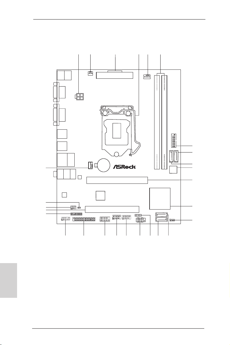
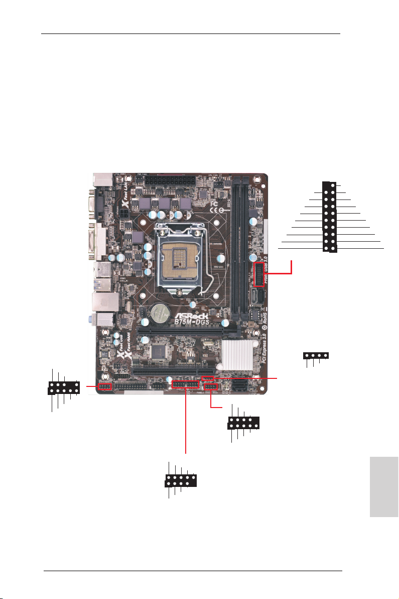
Motherboard Layout
Int e l
B75
64Mb
BIOS
DDR3 _A1 ( 64 bit , 240- pin mo dule )
CMOS
Batt ery
Supe r
I/O
ATXP WR1
DDR3 _B1 ( 64 bit , 240- pin mo dule )
PCIE1
PCI1
ATX12V1
PS2
Keybo ard
PS2
Mouse
VGA 1
AUDIO
CODEC
LAN
PHY
Top:
RJ-4 5
USB 2. 0
T: USB2
B: USB 3
Top:
Lin e In
Cen ter:
Fro nt
Bot tom:
Mic In
USB 3.0
T: USB0
B: USB1
USB 2.0
T: USB0
B: USB1
HD_AUDI O1
1
COM1
1
IR1
1
USB4_5
1
USB6_7
1
HDLED RES ET
PLED PWRBTN
PANEL1
1
SATA2_2
1
SPEAKE R1
SATA2_3
SATA2_1
SATA3_0
PWR_FAN 1
CPU_FAN 1
CHA_FAN 1
CLRCMO S1
1
B75M-DGS
PCI E xpre ss 3. 0
X
Fas t LAN
RoH S
LPT1
1
2 3
4
5
6
7
8
11
9
12
10
14
13
15
16
18
19
17
20
21
22
23
24
27
USB3_2_3
X
Fas t USB
X
Fas t RAM
1
CI1
25
DVI 1
1
Fro nt USB 3.0
TPMS1
1
26
English
2
1 ATX 12V Power Connector (ATX12V1)
2 Power Fan Connector (PWR_FAN1)
3 ATX Power Connector (ATXPWR1)
4 1155-Pin CPU Socket
5 CPU Fan Connector (CPU_FAN1)
6 2 x 240-pin DDR3 DIMM Slots
(DDR3_A1, DDR3_B1)
7 USB 3.0 Header (USB3_2_3)
8 SATA2 Connector (SATA2_1)
9 SATA3 Connector (SATA3_0)
10 SPI Flash Memory (64Mb)
11 PCI Express 3.0 x16 Slot (PCIE1)
12 Intel B75 Chipset
13 Clear CMOS Jumper (CLRCMOS1)
ASRock B75M-DGS R2.0 Motherboard
14 SATA2 Connector (SATA2_2)
15 SATA2 Connector (SATA2_3)
16 Chassis Speaker Header (SPEAKER1)
17 System Panel Header (PANEL1)
18 USB 2.0 Header (USB6_7)
19 USB 2.0 Header (USB4_5)
20 COM Port Header (COM1)
21 Print Port Header (LPT1)
22 Front Panel Audio Header (HD_AUDIO1)
23 TPM Header (TPMS1)
24 PCI Slot (PCI1)
25 Infrared Module Header (IR1)
26 Chassis Intrusion Header (CI1)
27 Chassis Fan Connector (CHA_FAN1)
Page 3
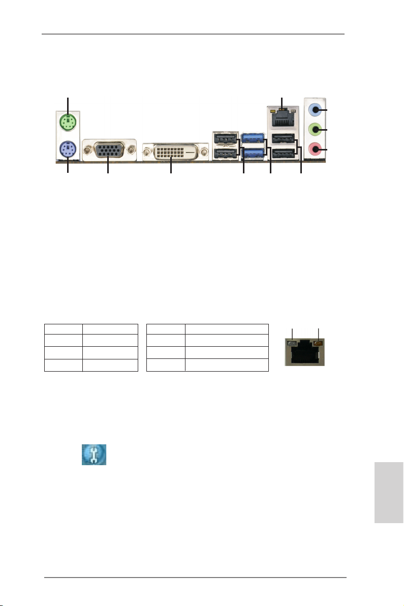
I/O Panel
1
2
3
4
5
11
1 PS/2 Mouse Port (Green) 7 USB 3.0 Ports (USB3_01)
* 2 LAN RJ-45 Port 8 USB 2.0 Ports (USB01)
3 Line In (Light Blue) 9 DVI-D Port (DVI1)
** 4 Front Speaker (Lime) 10 D-Sub Port (VGA1)
5 Microphone (Pink) 11 PS/2 Keyboard Port (Purple)
6 USB 2.0 Ports (USB23)
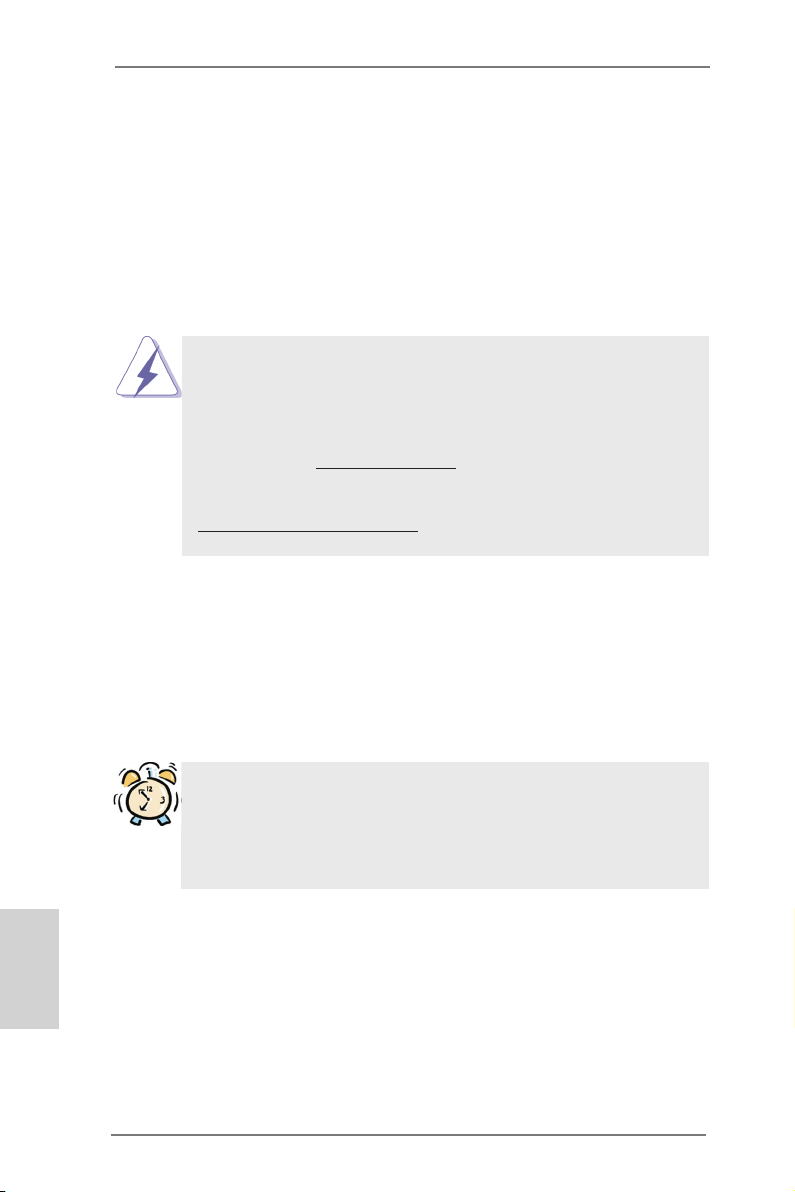
* There are two LED next to the LAN port. Please refer to the table below for the LAN port LED
indications.
Activity/Link LED SPEED LED
Status Description Status Description
10
9
LAN Port LED Indications
8
7
6
ACT/LINK
LED
SPEED
LED
Off No Link Off 10Mbps connection
Blinking Data Activity Orange 100Mbps connection
On Link Green 1Gbps connection
LAN Port
** To enable Multi-Streaming function, you need to connect a front panel audio cable to the front
panel audio header. Please refer to below steps for the software setting of Multi-Streaming.
For Windows® XP:
After restarting your computer, you will nd “Mixer” tool on your system. Please select “Mixer
ToolBox” , click “Enable playback multi-streaming”, and click “ok”. Choose “2CH” or
“4CH” and then you are allowed to select “Realtek HDA Primary output” to use Rear Speaker
and Front Speaker, or select “Realtek HDA Audio 2nd output” to use front panel audio. Then
reboot your system.
For Windows® 8 / 7 / VistaTM:
After restarting your computer, please double-click “Realtek HD Audio Manager” on the
system tray. Set “Speaker Conguration” to “Quadraphonic” or “Stereo”. Click “Device
advanced settings”, choose “Make front and rear output devices playbacks two different audio
streams simultaneously”, and click “ok”. Then reboot your system.
ASRock B75M-DGS R2.0 Motherboard
English
3
Page 4
1. Introduction
Thank you for purchasing ASRock B75M-DGS R2.0 motherboard, a reliable motherboard produced under ASRock’s consistently stringent quality control. It delivers
excellent performance with robust design conforming to ASRock’s commitment to
quality and endurance.
This Quick Installation Guide contains introduction of the motherboard and step-by-
step installation guide. More detailed information of the motherboard can be found
in the user manual presented in the Support CD.
Because the motherboard specications and the BIOS software might be
updated, the content of this manual will be subject to change without no-
tice. In case any modications of this manual occur, the updated version
will be available on ASRock website without further notice. You may nd
the latest VGA cards and CPU support lists on ASRock website as well.
ASRock website http://www.asrock.com
If you require technical support related to this motherboard, please visit
our website for specic information about the model you are using.
www.asrock.com/support/index.asp
1.1 Package Contents
ASRock B75M-DGS R2.0 Motherboard (Micro ATX Form Factor)
ASRock B75M-DGS R2.0 Quick Installation Guide
ASRock B75M-DGS R2.0 Support CD
2 x Serial ATA (SATA) Data Cables (Optional)
1 x I/O Panel Shield
English
4
ASRock Reminds You...
To get better performance in Windows® 8 / 8 64-bit / 7 / 7 64-bit / Vista
VistaTM 64-bit, it is recommended to set the BIOS option in Storage Con-
guration to AHCI mode. For the BIOS setup, please refer to the “User
Manual” in our support CD for details.
TM
ASRock B75M-DGS R2.0 Motherboard
/
Page 5

1.2 Specications
Platform - Micro ATX Form Factor
- All Solid Capacitor design
CPU - Supports 3rd and 2nd Generation Intel® CoreTM i7 / i5 / i3 in
LGA1155 Package
- Supports Intel® Turbo Boost 2.0 Technology
- Supports Hyper-Threading Technology
Chipset - Intel® B75
- Supports Intel® Small Business Advantage (see CAUTION 1)
- Supports Intel® Rapid Start Technology and Smart Connect
Technology
Memory - Dual Channel DDR3 Memory Technology
- 2 x DDR3 DIMM slots
- Supports DDR3 1600/1333/1066 non-ECC, un-buffered
memory (DDR3 1600 with Intel® Ivy Bridge CPU, DDR3
1333 with Intel® Sandy Bridge CPU)
- Max. capacity of system memory: 16GB (see CAUTION 2)
- Supports Intel® Extreme Memory Prole (XMP)1.3/1.2
Expansion Slot - 1 x PCI Express 3.0 x16 slot (PCIE1: x16 mode)
(see CAUTION 3)
* PCIE 3.0 is only supported with Intel® Ivy Bridge CPU. With
Intel® Sandy Bridge CPU, it only supports PCIE 2.0.
- 1 x PCI slot
Graphics * Intel® HD Graphics Built-in Visuals and the VGA outputs
can be supported only with processors which are GPU
integrated.
- Supports Intel® HD Graphics Built-in Visuals: Intel® Quick
Sync Video 2.0, Intel® InTruTM 3D, Intel® Clear Video HD
Technology, Intel® InsiderTM, Intel® HD Graphics 2500/4000
with Intel® Ivy Bridge CPU
- Supports Intel® HD Graphics Built-in Visuals: Intel® Quick
Sync Video, Intel® InTruTM 3D, Intel® Clear Video HD
Technology, Intel® HD Graphics 2000/3000, Intel® Advanced
Vector Extensions (AVX) with Intel® Sandy Bridge CPU
- Pixel Shader 5.0, DirectX 11 with Intel® Ivy Bridge CPU.
Pixel Shader 4.1, DirectX 10.1 with Intel® Sandy Bridge
CPU.
- Max. shared memory 1760MB with Intel® Ivy Bridge CPU.
Max. shared memory 1759MB with Intel® Sandy Bridge
CPU.
English
ASRock B75M-DGS R2.0 Motherboard
5
Page 6

English
- Dual VGA Output: support DVI-D and D-Sub ports by
independent display controllers
- Supports DVI-D with max. resolution up to 1920x1200 @
60Hz
- Supports D-Sub with max. resolution up to 2048x1536 @
75Hz
- Supports HDCP function with DVI-D port
- Supports Full HD 1080p Blu-ray (BD) / HD-DVD playback
with DVI-D port
Audio - 5.1 CH HD Audio (Realtek ALC662 Audio Codec)
LAN - PCIE x1 Gigabit LAN 10/100/1000 Mb/s
- Realtek RTL8111E
- Supports Wake-On-LAN
- Supports LAN Cable Detection
- Supports Energy Efcient Ethernet 802.3az
- Supports PXE
Rear Panel I/O I/O Panel
- 1 x PS/2 Mouse Port
- 1 x PS/2 Keyboard Port
- 1 x D-Sub Port
- 1 x DVI-D Port
- 4 x Ready-to-Use USB 2.0 Ports
- 2 x Ready-to-Use USB 3.0 Ports
- 1 x RJ-45 LAN Port with LED (ACT/LINK LED and SPEED
LED)
- HD Audio Jack: Line in/Front Speaker/Microphone
SATA3 - 1 x SATA3 6.0 Gb/s connector, supports NCQ, AHCI and
Hot Plug functions
USB3.0
- 1 x Front USB 3.0 header (supports 2 USB 3.0 ports),
supports USB 1.1/2.0/3.0 up to 5Gb/s
Connector - 3 x SATA2 3.0 Gb/s connectors, support NCQ, AHCI and
Hot Plug functions
- 1 x IR header
- 1 x Print port header
- 1 x COM port header
- 1 x Chassis Intrusion header
- 1 x TPM Header
- 1 x CPU Fan connector (4-pin)
- 1 x Chassis Fan connector (4-pin)
- 2 x Rear USB 3.0 ports, support USB 1.1/2.0/3.0 up to 5Gb/s
- 1 x SATA3 6.0Gb/s connector
6
ASRock B75M-DGS R2.0 Motherboard
Page 7
- 1 x Power Fan connector (3-pin)
- 24 pin ATX power connector
- 4 pin 12V power connector
- Front panel audio connector
- 2 x USB 2.0 headers (support 4 USB 2.0 ports)
- 1 x USB 3.0 header (supports 2 USB 3.0 ports)
BIOS Feature - 64Mb AMI UEFI Legal BIOS with GUI support
- Supports “Plug and Play”
- ACPI 1.1 Compliance Wake Up Events
- Supports jumperfree
- SMBIOS 2.3.1 Support
- CPU Core, IGPU, DRAM, 1.8V PLL, VTT, VCCSA Voltage
Multi-adjustment
Support CD - Drivers, Utilities, AntiVirus Software (Trial Version),
CyberLink MediaEspresso 6.5 Trial, Google Chrome
Browser and Toolbar
Hardware - CPU Temperature Sensing
Monitor - Chassis Temperature Sensing
- CPU/Chassis/Power Fan Tachometer
- CPU/Chassis Quiet Fan (Allows Chassis Fan Speed Auto-
Adjust by CPU Temperature)
- CPU/Chassis Fan Multi-Speed Control
- CASE OPEN detection
- Voltage Monitoring: +12V, +5V, +3.3V, CPU Vcore
OS - Microsoft® Windows® 8 / 8 64-bit / 7 / 7 64-bit / VistaTM /
VistaTM 64-bit / XP / XP 64-bit compliant (see CAUTION 4)
Certications - FCC, CE, WHQL
- ErP/EuP Ready (ErP/EuP ready power supply is required)
* For detailed product information, please visit our website: http://www.asrock.com
WARNING
Please realize that there is a certain risk involved with overclocking,
including adjusting the setting in the BIOS, applying Untied Overclocking
Technology, or using third-party overclocking tools. Overclocking may
affect your system’s stability, or even cause damage to the components
and devices of your system. It should be done at your own risk and
expense. We are not responsible for possible damage caused by
overclocking.
ASRock B75M-DGS R2.0 Motherboard
English
7
Page 8

CAUTION!
1. Intel® Small Business Advantage is a customizable platform integrated with IT tools, which helps maximize employee productivity, PC performance, and data security. There are applications
including Software Monitor, PC Health Center, Data Backup &
Restore, Energy Saver and USB Blocker.
2. Due to the operating system limitation, the actual memory size
may be less than 4GB for the reservation for system usage
under Windows® 8 / 7 / VistaTM / XP. For Windows® OS with 64bit CPU, there is no such limitation. You can use ASRock XFast
RAM to utilize the memory that Windows® cannot use.
3. Only PCIE1 slot supports Gen 3 speed. To run the PCI Express
in Gen 3 speed, please install an Ivy Bridge CPU. If you install
a Sandy Bridge CPU, the PCI Express will run only at PCI Express Gen 2 speed.
4. ASRock XFast RAM is not supported by Microsoft® Windows®
XP / XP 64-bit. Intel® Smart Connect Technology and Intel® USB
3.0 ports are not supported by Microsoft® Windows® VistaTM /
VistaTM 64-bit / XP / XP 64-bit.
English
8
ASRock B75M-DGS R2.0 Motherboard
Page 9
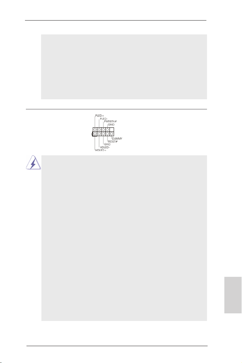
1.3 Pin Header Easy Installation Guide
1
PLED +
PLED -
PWRB TN#
HDLE D+
HDLE D-
GND
REST #
GND
DUMM Y
1
USB_ PWR
P-
P+
USB_ PWR
P-
P+
GND
GND
DUMM Y
1
GND
PRES ENCE#
MIC_ RET
MIC2 _L
MIC2 _R
OUT2 _R
J_SE NSE
OUT2 _L
OUT_ RET
1
+5V
DUMM Y
SPEA KER
DUMM Y
ASRock motherboard is equipped with pin headers with obvious colors which indicate you to recognize the crucial headers more easily. Please refer to below illustra-
tions for the pin denition of onboard headers. If you want to have more information
about the usage of these headers, please refer to “Jumpers Setup“ and “Onboard
Headers and Connectors“ for details.
Front Panel Audio Header
System Panel Header
Vbu s
Int A _P_S SRX-
Int A _P_S SRX+
GND
Int A _P_S STX-
Int A _P_S STX+
GND
Int A _P_D -
Int A _P_D +
Vbu s
1
USB 3.0 Header
Chassis Speaker Header
Int A _P_S SRX-
Int A _P_S SRX+
GND
Int A _P_S STX-
Int A _P_S STX+
GND
Int A _P_D -
Int A _P_D +
ID
USB 2.0 Header
English
9
ASRock B75M-DGS R2.0 Motherboard
Page 10
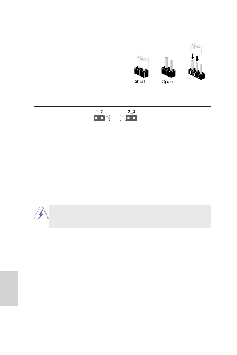
1.4 Jumpers Setup
The illustration shows how jumpers are
setup. When the jumper cap is placed on
pins, the jumper is “Short”. If no jumper cap
is placed on pins, the jumper is “Open”. The
illustration shows a 3-pin jumper whose
pin1 and pin2 are “Short” when jumper cap
is placed on these 2 pins.
Jumper Setting Description
Clear CMOS Jumper
(CLRCMOS1)
(see p.2, No. 13)
Note: CLRCMOS1 allows you to clear the data in CMOS. To clear and reset the
system parameters to default setup, please turn off the computer and unplug
the power cord from the power supply. After waiting for 15 seconds, use a
jumper cap to short pin2 and pin3 on CLRCMOS1 for 5 seconds. However,
please do not clear the CMOS right after you update the BIOS. If you need
to clear the CMOS when you just nish updating the BIOS, you must boot
up the system rst, and then shut it down before you do the clear-CMOS action. Please be noted that the password, date, time, user default prole, 1394
GUID and MAC address will be cleared only if the CMOS battery is removed.
Clear CMOSDefault
English
10
If you clear the CMOS, the case open may be detected. Please adjust
the BIOS option “Clear Status” to clear the record of previous chassis
intrusion status.
ASRock B75M-DGS R2.0 Motherboard
Page 11
1.5 Onboard Headers and Connectors
Onboard headers and connectors are NOT jumpers. Do NOT place
jumper caps over these headers and connectors. Placing jumper caps
over the headers and connectors will cause permanent damage of the
motherboard!
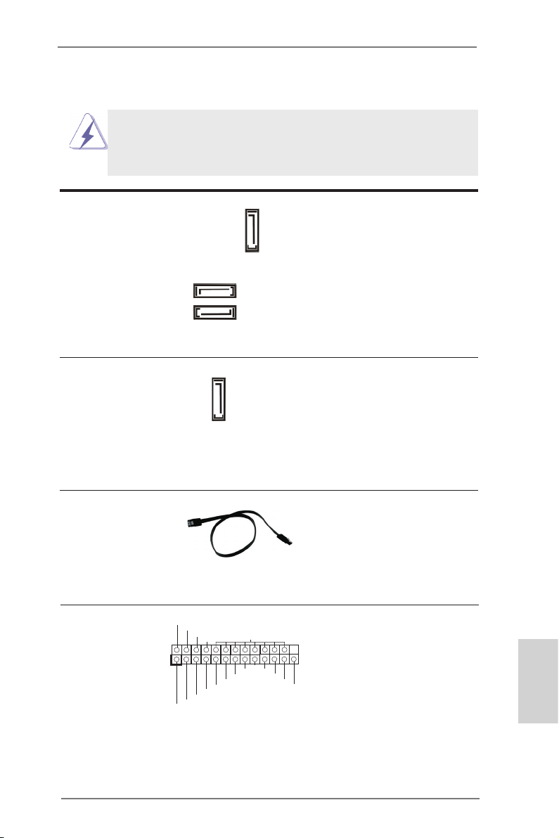
Serial ATA2 Connectors These three Serial ATA2
(SATA2_1: see p.2, No. 8)
(SATA2_2: see p.2, No. 14)
(SATA2_3: see p.2, No. 15)
SATA2 interface allows up to
3.0 Gb/s data transfer rate.
Serial ATA3 Connector This Serial ATA3 (SATA3)
(SATA3_0: see p.2, No. 9)
cables for internal storage
devices. The current SATA3
interface allows up to 6.0 Gb/s
data transfer rate.
(SATA2) connectors support
SATA data cables for internal
SATA2_1
storage devices. The current
SATA2_2
SATA2_3
connector supports SATA data
SATA3_0
Serial ATA (SATA) Either end of the SATA data
Data Cable cable can be connected to the
(Optional)
SATA / SATA2 / SATA3 hard
disk or the SATA2 / SATA3
connector on this motherboard.
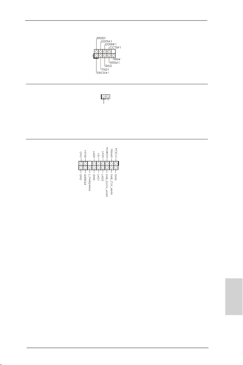
Print Port Header This is an interface for print port
(25-pin LPT1)
(see p.2, No. 21)
cable that allows convenient
connection of printer devices.
1
AFD #
STB #
ERR OR#
PIN I T#
SPD 1
SPD 0
SLI N #
SPD 2
SPD 3
SPD 4
SPD 5
SPD 6
GND
SPD 7
ACK #
BUS Y
PE
SLC T
ASRock B75M-DGS R2.0 Motherboard
English
11
Page 12
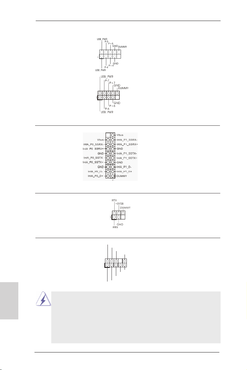
USB 2.0 Headers Besides four default USB 2.0
(9-pin USB4_5)
(see p.2, No. 19)
ports on the I/O panel, there are
two USB 2.0 headers on this
motherboard. Each USB 2.0
header can support two USB 2.0
(9-pin USB6_7)
(see p.2, No. 18)
ports.
USB 3.0 Header Besides two default USB 3.0
(19-pin USB3_2_3)
(see p.2, No. 7)
ports on the I/O panel, there is
one USB 3.0 header on this
motherboard. This USB 3.0
header can support two USB 3.0
ports.
Infrared Module Header This header supports an
(5-pin IR1)
optional wireless transmitting
(see p.2, No. 25)
and receiving infrared module.
English
12
Front Panel Audio Header This is an interface for front
(9-pin HD_AUDIO1)
(see p.2, No. 22)
panel audio cable that allows
convenient connection and
control of audio devices.
1
GND
PRE SENC E#
MIC 2_R
MIC 2_L
MIC _RET
J_S ENSE
OUT 2_R
OUT _RET
OUT 2_L
1. High Denition Audio supports Jack Sensing, but the panel wire on the
chassis must support HDA to function correctly. Please follow the
instruction in our manual and chassis manual to install your system.
2. If you use AC’97 audio panel, please install it to the front panel audio
header as below:
A. Connect Mic_IN (MIC) to MIC2_L.
B. Connect Audio_R (RIN) to OUT2_R and Audio_L (LIN) to OUT2_L.
ASRock B75M-DGS R2.0 Motherboard
Page 13
C. Connect Ground (GND) to Ground (GND).
D. MIC_RET and OUT_RET are for HD audio panel only. You don’t need
to connect them for AC’97 audio panel.
E. To activate the front mic.
For Windows® XP / XP 64-bit OS:
Select “Mixer”. Select “Recorder”. Then click “FrontMic”.
For Windows® 8 / 8 64-bit / 7 / 7 64-bit / VistaTM / VistaTM 64-bit OS:
Go to the “FrontMic” Tab in the Realtek Control panel. Adjust
“Recording Volume”.
System Panel Header This header accommodates
(9-pin PANEL1)
(see p.2, No. 17)
several system front panel
functions.
Connect the power switch, reset switch and system status indicator on the
chassis to this header according to the pin assignments below. Note the
positive and negative pins before connecting the cables.
PWRBTN (Power Switch):
Connect to the power switch on the chassis front panel. You may congure
the way to turn off your system using the power switch.
RESET (Reset Switch):
Connect to the reset switch on the chassis front panel. Press the reset
switch to restart the computer if the computer freezes and fails to perform a
normal restart.
PLED (System Power LED):
Connect to the power status indicator on the chassis front panel. The LED
is on when the system is operating. The LED keeps blinking when the system is in S1/S3 sleep state. The LED is off when the system is in S4 sleep
state or powered off (S5).
HDLED (Hard Drive Activity LED):
Connect to the hard drive activity LED on the chassis front panel. The LED
is on when the hard drive is reading or writing data.
The front panel design may differ by chassis. A front panel module mainly
consists of power switch, reset switch, power LED, hard drive activity LED,
speaker and etc. When connecting your chassis front panel module to this
header, make sure the wire assignments and the pin assign-ments are
matched correctly.
ASRock B75M-DGS R2.0 Motherboard
English
13
Page 14
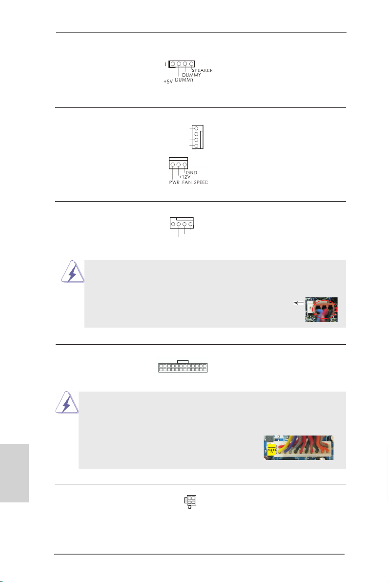
Chassis Speaker Header Please connect the chassis
(4-pin SPEAKER 1)
(see p.2, No. 16)
speaker to this header.
Chassis and Power Fan Connectors Please connect the fan cables
(4-pin CHA_FAN1)
(see p.2, No. 27)
to the fan connectors and match
the black wire to the ground pin.
CHA_FAN1 supports Fan
(3-pin PWR_FAN1)
(see p.2, No. 2)
Control.
FAN _SPE ED_C ONTR OL
CHA _FAN _SPE ED
+12 V
GND
English
CPU Fan Connector Please connect the CPU fan
(4-pin CPU_FAN1)
(see p.2, No. 5)
cable to the connector and
match the black wire to the
ground pin.
4 3 2 1
+12 V
FAN_ SPEE D_CO NTRO L
CPU _FAN_ SPEE D
GND
Though this motherboard provides 4-Pin CPU fan (Quiet Fan) support, the 3-Pin
CPU fan still can work successfully even without the fan speed control function.
If you plan to connect the 3-Pin CPU fan to the CPU fan connector on this
motherboard, please connect it to Pin 1-3.
ATX Power Connector Please connect an ATX power
(24-pin ATXPWR1)
(see p.2, No. 3)
supply to this connector.
24 13
12 1
Pin 1-3 Connected
3-Pin Fan Installation
Though this motherboard provides 24-pin ATX power connector, it can still work if
you adopt a traditional 20-pin ATX power supply. To use the 20-pin ATX power
supply, please plug your power supply along with Pin 1 and Pin 13.
24 13
20-Pin ATX Power Supply Installation
12 1
ATX 12V Power Connector Please connect an ATX 12V
(4-pin ATX12V1)
(see p.2, No. 1)
power supply to this connector.
14
ASRock B75M-DGS R2.0 Motherboard
Page 15
Serial port Header This COM1 header supports a
1
(9-pin COM1)
(see p.2, No. 20)
serial port module.
Chassis Intrusion Header This motherboard supports
(2-pin CI1)
CASE OPEN detection feature
(see p.2, No. 26)
that detects if the chassis cover
1
Sig n al
GND
has been removed. This feature
requires a chassis with chassis
intrusion detection design.
TPM Header This connector supports
(17-pin TPMS1)
(see p.2, No. 23)
Trusted Platform Module (TPM)
system, which can securely
store keys, digital certicates,
passwords, and data. A TPM
system also helps enhance
network security, protects
digital identities, and ensures
platform integrity.
English
ASRock B75M-DGS R2.0 Motherboard
15
Page 16

2. BIOS Information
The Flash Memory on the motherboard stores BIOS Setup Utility. When you start up
the computer, please press <F2> or <Del> during the Power-On-Self-Test (POST)
to enter BIOS Setup utility; otherwise, POST continues with its test routines. If you
wish to enter BIOS Setup after POST, please restart the system by pressing <Ctl>
+ <Alt> + <Delete>, or pressing the reset button on the system chassis. The BIOS
Setup program is designed to be user-friendly. It is a menu-driven program, which
allows you to scroll through its various sub-menus and to select among the predetermined choices. For the detailed information about BIOS Setup, please refer to the
User Manual (PDF le) contained in the Support CD.
3. Software Support CD information
®
This motherboard supports various Microsoft
64-bit / 7 / 7 64-bit / VistaTM / Vista
came with the motherboard contains necessary drivers and useful utilities that will
enhance motherboard features. To begin using the Support CD, insert the CD into
your CD-ROM drive. It will display the Main Menu automatically if “AUTORUN” is
enabled in your computer. If the Main Menu does not appear automatically, locate
and double-click on the le “ASSETUP.EXE” from the BIN folder in the Support CD
to display the menus.
TM
Windows® operating systems: 8 / 8
64-bit / XP / XP 64-bit. The Support CD that
English
16
ASRock B75M-DGS R2.0 Motherboard
Page 17

Spezikationen
Plattform - Micro ATX-Formfaktor
- Alle Feste Kondensatordesign
CPU - Unterstützt Intel® CoreTM i7- / i5- / i3-Prozessoren der 3ten
und 2ten Generation im LGA1155-Package
- Unterstützt Intel® Turbo Boost 2.0-Technologie
- Unterstützt Hyper-Threading-Technologie
Chipsatz - Intel® B75
- Unterstützt Intel® Small Business Advantage
- Unterstützt Intel® Rapid Start Technology und Smart
Connect Technology
Speicher - Dual-Kanal DDR3 Speichertechnologie
- 2 x Steckplätze für DDR3
- Unterstützt DDR3 1600/1333/1066 non-ECC, ungepufferter
Speicher (DDR3 1600 mit Intel® Ivy Bridge-Prozessor,
DDR3 1333 mit Intel® Sandy Bridge-Prozessor)
- Max. Kapazität des Systemspeichers: 16GB
- Unterstützt Intel® Extreme Memory Prole (XMP)1.3/1.2
Erweiterungs- - 1 x PCI Express 3.0 x16-Steckplätze (PCIE1: x16-Modus)
steckplätze * PCIE 3.0 wird nur mit Intel® Ivy Bridge-Prozessor
unterstützt. Mit Intel® Sandy Bridge-Prozessor wird nur
PCIE 2.0 unterstützt.
- 1 x PCI-Steckplätze
Onboard-VGA * Integrierte Intel® HD-Grakdarstellungen und die VGA-
Ausgänge können nur durch GPU-integrierte Prozessoren
unterstützt werden.
- Unterstützt hochauösende integrierte Intel®-Graklösungen:
Intel® Quick-Sync-Video 2.0, Intel® InTruTM 3D, Intel® Clear Video-Technik (HD), Intel® InsiderTM, Intel® HD Graphics
2500/4000 mit Intel® Ivy Bridge-Prozessor
- Unterstützt hochauösende integrierte Intel®-Graklösungen:
Intel® Quick-Sync-Video, Intel® InTruTM 3D, Intel® Clear Video-Technik (HD), Intel® HD Graphics 2000/3000, Intel®
Advanced Vector Extensions (AVX) mit Intel® Sandy Bridge Prozessor
- Pixel Shader 5.0, DirectX 11 mit Intel® Ivy Bridge-Prozessor,
Pixel Shader 4.1, DirectX 10.1 mit Intel® Sandy Bridge Prozessor
- Maximal gemeinsam genutzter Speicher 1760MB mit Intel®
Ivy Bridge-Prozessor. Maximal gemeinsam genutzter
Deutsch
ASRock B75M-DGS R2.0 Motherboard
17
Page 18

Deutsch
Speicher 1759MB mit Intel® Sandy Bridge-Prozessor.
- Doppel-VGA Ausgabe: unterstützt DVI-D und D-Sub Ports
durch unabhängige Bildschirmanzeige Kontrolleure
- Unterstützt DVI-D mit einer maximalen Auösung von
1920 x 1200 bei 60 Hz
- Unterstützt D-Sub mit einer maximalen Auösung von 2048
x 1536 bei 75 Hz
- Unterstützt HDCP-Funktion mit DVI-D-Port
- Unterstutzt 1080p Blu-ray (BD) / HD-DVD-Wiedergabe mit
DVI-D-Port
Audio - 5.1 CH HD Audio (Realtek ALC662 Audio Codec)
LAN - PCIE x1 Gigabit LAN 10/100/1000 Mb/s
- Realtek RTL8111E
- Unterstützt Wake-On-LAN
- Unterstützt LAN-Kabelerkennung
- Unterstützt energieefzientes Ethernet 802.3az
- Unterstützt PXE
E/A-Anschlüsse I/O Panel
an der Rückseite - 1 x PS/2-Mausanschluss
- 1 x PS/2-Tastaturanschluss
- 1 x D-Sub port
- 1 x DVI-D port
- 4 x Standard-USB 2.0-Anschlüsse
- 2 x Standard-USB 3.0-Anschlüsse
- 1 x RJ-45 LAN Port mit LED (ACT/LINK LED und SPEED
LED)
- HD Audiobuchse: Audioeingang / Lautsprecher vorne /
Mikrofon
SATA3 - 1 x SATA 3-Anschlüsse (6,0 Gb/s); unterstützt NCQ-, AHCI-
und Hot Plug Funktionen
USB3.0 - 2 x USB 3.0-Ports an der Rückseite, unterstützt USB
1.1/2.0/3.0 mit bis zu 5 Gb/s
- 1 x USB 3.0-Header (unterstützt zwei USB 3.0-Ports) an der
Vorderseite, unterstützt USB 1.1/2.0/3.0 mit bis zu 5 Gb/s
Anschlüsse - 3 x SATA2 3,0 GB/s-Anschlüsse, unterstützen NCQ-, AHCI-
und Hot Plug Funktionen
- 1 x SATA3 6,0 GB/s-Anschlüsse
- 1 x Infrarot-Modul-Header
- 1 x Druckerport-Anschlussleiste
- 1 x COM-Anschluss-Header
- 1 x Verteiler für Gehäuseeindringversuche
18
ASRock B75M-DGS R2.0 Motherboard
Page 19

- 1 x TPM-Stiftleiste
- 1 x CPUlüfter-Anschluss (4-pin)
- 1 x Gehäuselüfter-Anschluss (4-pin)
- 1 x Stromlüfter-Anschluss (3-pin)
- 24-pin ATX-Netz-Header
- 4-pin anschluss für 12V-ATX-Netzteil
- Anschluss für Audio auf der Gehäusevorderseite
- 2 x USB 2.0-Anschlüsse (Unterstützung 4 zusätzlicher
USB 2.0-Anschlüsse)
- 1 x USB 3.0-Anschlüsse (Unterstützung 2 zusätzlicher
USB 3.0-Anschlüsse)
BIOS - 64Mb AMIs Legal BIOS UEFI mit GUI-Unterstützung
- Unterstützung für “Plug and Play”
- ACPI 1.1-Weckfunktionen
- JumperFree-Modus
- SMBIOS 2.3.1
- CPU Core, IGPU, DRAM, 1.8V PLL, VTT, VCCSA
Stromspannung Multianpassung
CD d’assistance - Pilotes, utilitaires, logiciel anti-virus (version d’évaluation),
CyberLink MediaEspresso 6.5 Trial, Google Chrome
Browser und Toolbar
Hardware Monitor - Überwachung der CPU-Temperatur
- Motherboardtemperaturerkennung
- Drehzahlmessung für CPU/Gehäuse/Strom lüfter
- Geräuscharmer CPU-/Gehäuselüfter (ermöglicht die au
tomatische Anpassung der Gehäuselüftergeschwindigkeit
durch CPU-Temperatur)
- Mehrstuge Geschwindigkeitssteuerung für CPU/Gehäuse
lüfter
- GEHÄUSE OFFEN-Erkennung
- Spannungsüberwachung: +12V, +5V, +3.3V, Vcore
®
Betriebssysteme - Unterstützt Microsoft
VistaTM / Vista
TM
Windows® 8 / 8 64-Bit / 7 / 7 64-Bit /
64-Bit / XP / XP 64-Bit
Zertizierungen - FCC, CE, WHQL
- Gemäß Ökodesign-Richtlinie (ErP/EuP) (Stromversorgung
gemäß Ökodesign-Richtlinie (ErP/EuP) erforderlich)
* Für die ausführliche Produktinformation, besuchen Sie bitte unsere Website:
http://www.asrock.com
Deutsch
ASRock B75M-DGS R2.0 Motherboard
19
Page 20

Français
Spécications
Format - Facteur de forme Micro ATX
- Conception à condensateur robuste
CPU - Prend en charge les processeurs Intel® CoreTM i7 / i5 / i3
2ème et 3ème génération sur socket LGA1155
- Prend en charge la technologie Intel® Turbo Boost 2.0
- Prise en charge de la technologie Hyper-Threading
Chipsets - Intel® B75
- Supports Intel® Small Business Advantage
- Prend en charge les technologies Intel® Rapid Start et Smart
Connect
Mémoire - Compatible avec la Technologie de Mémoire à Canal
- 2 x slots DIMM DDR3
- Supporter DDR3 1600/1333/1066 non-ECC, sans
amortissement mémoire (DDR3 1600 avec CPU Intel® Ivy
Bridge, DDR3 1333 avec CPU Intel® Sandy Bridge)
- Capacité maxi de mémoire système: 16GB
- Prend en charge le prol de mémoire extrême Intel® (XMP)
1.3/1.2
Slot d’extension - 1 x slot PCI Express 3.0 x16 (PCIE1 : mode x16)
* PCIE 3.0 n’est pris en charge qu’avec le processeur Intel®
Ivy Bridge. Avec le processeur Intel® Sandy Bridge, seul
PCIE 2.0 est pris en charge.
- 1 x slot PCI
VGA sur carte * Intel® HD Graphics avec visuels intégrés (Built-in Visuals) et
les sorties VGA sont uniquement pris en charge par les
processeurs à GPU intégré.
- Supporte Intel® HD Graphics Built-in Visuals: Intel® Quick
Sync Video 2.0, Intel® InTruTM 3D, Intel® Clear Video HD
Technology, Intel® InsiderTM, Intel® HD Graphics 2500/4000
avec processeur Intel® Ivy Bridge CPU
- Supporte Intel® HD Graphics Built-in Visuals: Intel® Quick
Sync Video, Intel® InTruTM 3D, Intel® Clear Video HD
Technology, Intel® HD Graphics 2000/3000, Intel® Advanced
Vector Extensions (AVX) avec processeur Intel® Sandy
Bridge CPU
- Pixel Shader 5.0, DirectX 11 avec CPU Intel® Ivy Bridge,
Pixel Shader 4.1, DirectX 10.1 avec CPU Intel® Sandy
Bridge
- Mémoire partagée max 1760MB avec processeur Intel® Ivy
20
ASRock B75M-DGS R2.0 Motherboard
Page 21

Bridge CPU. Mémoire partagée max 1759MB avec
processeur Intel® Sandy Bridge CPU.
- Output de VGA Duel: supporter DVI-D et D-Sub ports par
les controleurs de display independents
- Prend en charge le DVI-D avec une résolution maximale
jusqu’à 1920x1200 @ 60Hz
- Prend en charge le D-Sub avec une résolution maximale
jusqu’à 2048x1536 @ 75Hz
- Prise en charge de la fonction HDCP avec ports DVI-D
- Supporter 1080p Blu-ray(BD)/ lecteur de HD-DVD avec
ports DVI-D
Audio - 5,1 CH HD Audio (Realtek ALC662 Audio Codec)
LAN - PCIE x1 Gigabit LAN 10/100/1000 Mb/s
- Realtek RTL8111E
- Support du Wake-On-LAN
- Prise en charge de la détection de câble LAN
- Prend en charge la norme Energy Efcient Ethernet
(Ethernet à efcacité énergétique) 802.3az
- Supporte PXE
Panneau arrière I/O Panel
- 1 x port souris PS/2
- 1 x port clavier PS/2
- 1 x port D-Sub
- 1 x port DVI-D
- 4 x ports USB 2.0 par défaut
- 2 x ports USB 3.0 par défaut
- 1 x port LAN RJ-45 avec LED (ACT/LED CLIGNOTANTE et
LED VITESSE)
- Prise HD Audio: Entrée Ligne / Haut-parleur frontal /
Microphone
SATA3 - 1 x connecteurs SATA3 6,0 Gb/s, prennent en charge les
fonctions NCQ, AHCI et Hot Plug
USB 3.0 - 2 x ports USB3.0 à l’arrière, prennent en charge USB
1.1/2.0/3.0 jusqu’à 5 Gb/s
- 1 x barrette USB3.0 en façade (prend en charge 2 ports
USB 3.0), prend en charge USB 1.1/2.0/3.0 jusqu’à 5 Gb/s
Connecteurs - 3 x connecteurs SATA2, prennent en charge un taux de
transfert de données pouvant aller jusqu’à 3.0Go/s,
supporte NCQ, AHCI et Hot Plug (Branchement à chaud)
- 1 x connecteurs SATA3, prennent en charge un taux de
transfert de données pouvant aller jusqu’à 6.0Go/s
Français
ASRock B75M-DGS R2.0 Motherboard
21
Page 22

Français
- 1 x En-tête du module infrarouge
- 1 x embase de port d’impression
- 1 x En-tête de port COM
- 1 x Embase d’intrusion châssis
- 1 x embase TPM
- 1 x Connecteur pour ventilateur de CPU (br. 4)
- 1 x Connecteur pour ventilateur de Châssis (br. 4)
- 1 x Connecteur pour ventilateur de pouvoir (br. 3)
- br. 24 connecteur d’alimentation ATX
- br. 4 connecteur d’alimentation 12V ATX
- Connecteur audio panneau avant
- 2 x En-tête USB 2.0 (prendre en charge 4 ports USB 2.0
supplémentaires)
- 1 x En-tête USB 3.0 (prendre en charge 2 ports USB 3.0
supplémentaires)
BIOS - 64Mb AMI UEFI Legal BIOS avec support GUI
- Support du “Plug and Play”
- Compatible pour événements de réveil ACPI 1.1
- Gestion jumperless
- Support SMBIOS 2.3.1
- CPU Core, IGPU, DRAM, 1.8V PLL, VTT, VCCSA Tension
Multi-ajustement
CD d’assistance - Pilotes, utilitaires, logiciel anti-virus (version d’évaluation),
CyberLink MediaEspresso 6.5 Trial, Google Chrome
Browser et Toolbar
Surveillance - Détection de la température de l’UC
système - Mesure de température de la carte mère
- Tachéomètre ventilateur processeur/châssis/pouvoir
ventilateur
- Ventilateur silencieux pour unité centrale/châssis (permet le
réglage automatique de la vitesse du ventilateur pour
châssis, selon la température de l’unité centrale)
- Commande de ventilateur CPU/Châssis à plusieurs
vitesses
- Détection d’OUVERTURE DE BOÎTIER
- Monitoring de la tension: +12V, +5V, +3.3V, Vcore
OS - Microsoft® Windows® 8 / 8 64-bit / 7 / 7 64-bit / VistaTM /
Vista
TM
64-bit / XP / XP 64-bit
Certications - FCC, CE, WHQL
- Prêt pour ErP/EuP (alimentation Prêt pour ErP/EuP requise)
22
ASRock B75M-DGS R2.0 Motherboard
Page 23

* Pour de plus amples informations sur les produits, s’il vous plaît visitez notre site web:
http://www.asrock.com
ASRock B75M-DGS R2.0 Motherboard
Français
23
Page 24

Italiano
Speciche
Piattaforma - Micro ATX Form Factor
- Design condensatore robusto
Processore - Supporta Intel® CoreTM i7 / i5 / i3 di 3a e 2a generazione in un
pacchetto LGA1155
- Supporto della tecnologia Intel® Turbo Boost 2.0
- Supporto tecnologia Hyper Threading
Chipset - Intel® B75
- Supporta Intel® Small Business Advantage
- Supporta tecnologia Intel® Rapid Start Technology e Smart
Connect Technology
Memoria - Supporto tecnologia Dual Channel Memory
- 2 x slots DDR3 DIMM
- Supporto DDR3 1600/1333/1066 non-ECC, momoria senza
buffer (DDR3 1600 con CPU Intel® Ivy Bridge, DDR3 1333 con
CPU Intel® Sandy Bridge)
- Capacità massima della memoria di sistema: 16GB
- Supporto di Intel® XMP (Extreme Memory Prole)1.3/1.2
Slot di - 1 x Alloggio PCI Express 3.0 x16 (PCIE1 : modalità x16)
espansione * PCIE 3.0 è supportato soltanto con la CPU Intel® Ivy Bridge.
Con la CPU Intel® Sandy Bridge, supporta solamente PCIE
2.0.
- 1 x Alloggio PCI
VGA su scheda * Le uscite Intel® HD Graphics Built-in Visuals e VGA possono
essere supportate solo con processori dotati di GPU
integrata.
- Supporta Intel® HD Graphics Built-in Visuals: Intel® Quick Sync
Video 2.0, Intel® InTruTM 3D, Intel® Clear Video HD Technology,
Intel® InsiderTM, Intel® HD Graphics 2500/4000 con CPU Intel®
Ivy Bridge
- Supporta Intel® HD Graphics Built-in Visuals: Intel® Quick Sync
Video, Intel® InTruTM 3D, Intel® Clear Video HD Technology,
Intel® HD Graphics 2000/3000, Intel® Advanced Vector
Extensions (AVX) con CPU Intel® Sandy Bridge
- Pixel Shader 5.0, DirectX 11 con CPU Intel® Ivy Bridge, Pixel
Shader 4.1, DirectX 10.1 con CPU Intel® Sandy Bridge
- Memoria massima condivisa 1760MB con CPU Intel®
Ivy Bridge. Memoria massima condivisa 1759MB con CPU
Intel® Sandy Bridge.
- Uscita VGA Doppia: supporto porte DVI-D e D-Sub tramite
24
ASRock B75M-DGS R2.0 Motherboard
Page 25

vericatore display indipendente
- Supporta DVI-D con risoluzione massima no a 1920x1200 @
60Hz
- Supporta D-Sub con risoluzione massima no a 2048x1536 @
75Hz
- Supporto della funzione HDCP con le porte DVI-D
- Supporto 1080p Blu-ray (BD) / HD-DVD riproduzione con le
porte DVI-D
Audio - 5.1 CH HD Audio (Realtek ALC662 Audio Codec)
LAN - PCIE x1 Gigabit LAN 10/100/1000 Mb/s
- Realtek RTL8111E
- Supporta Wake-On-LAN
- Supporta il rilevamento cavo LAN
- Supporto di Energy Efcient Ethernet 802.3az
- Supporta PXE
Pannello I/O Panel
posteriore I/O - 1 x porta PS/2 per mouse
- 1 x porta PS/2 per tastiera
- 1 x Porta D-Sub
- 1 x Porta DVI-D
- 4 x porte USB 2.0 già integrate
- 2 x porte USB 3.0 già integrate
- 1 x porte LAN RJ-45 con LED (LED azione/collegamento e
LED velocità)
- Connettore HD Audio: ingresso linea / cassa frontale /
microfono
SATA3 - 1 x Connettori SATA3 6,0Gb/s, supporto e delle funzioni NCQ,
AHCI e Hot Plug
USB 3.0 - 2 x porte USB 3.0 posteriori amministrate dal controller,
supporto di USB 1.1/2.0/3.0 no a 5Gb/s
- 1 x header USB 3.0 frontale (supporta 4 porte USB 3.0)
amministrato dal controller, supporto di USB 1.1/2.0/3.0 no a
5Gb/s
Connettori - 3 x connettori SATA2 3.0Go/s, sopporta e delle funzioni NCQ,
AHCI e Hot Plug
- 1 x connettori SATA3 6.0Go/s
- 1 x Collettore modulo infrarossi
- 1 x Collettore porta stampante
- 1 x collettore porta COM
- 1 x header di intrusione dello chassis
- 1 x header TPM
Italiano
ASRock B75M-DGS R2.0 Motherboard
25
Page 26

Italiano
- 1 x Connettore CPU ventola (4-pin)
- 1 x Connettore Chassis ventola (4-pin)
- 1 x Connettore Alimentazione ventola (3-pin)
- 24-pin collettore alimentazione ATX
- 4-pin connettore ATX 12V
- Connettore audio sul pannello frontale
- 2 x Collettore USB 2.0 (supporta 4 porte USB 2.0)
- 1 x Collettore USB 3.0 (supporta 2 porte USB 3.0)
BIOS - 64Mb AMI UEFI Legal BIOS con interfaccia di supporto
- Supporta “Plug and Play”
- Compatibile con ACPI 1.1 wake up events
- Supporta jumperfree
- Supporta SMBIOS 2.3.1
- Regolazione multi-voltaggio CPU Core, IGPU, DRAM, 1.8V
PLL, VTT, VCCSA
CD di - Driver, Utilità, Software AntiVirus (versione di prova),
supporto CyberLink MediaEspresso 6.5 Trial, Google Chrome Browser
e Toolbar
Monitoraggio - Sensore per la temperatura del processore
Hardware - Sensore temperatura scheda madre
- Indicatore di velocità per la ventola del CPU/Chassis/potenza
Alimentazione
- Ventola CPU/Chassis silenziosa (permette la regolazione
automatica della ventola dello chassis in base alla temperatura
della CPU)
- Ventola CPU/chassis con controllo di varie velocità
- Rilevamento CASE APERTO
- Voltaggio: +12V, +5V, +3.3V, Vcore
Compatibilità - Microsoft® Windows® 8 / 8 64 bit / 7 / 7 64 bit / VistaTM / Vista
SO
64 bit / XP / XP 64 bit
TM
Certicazioni - FCC, CE, WHQL
- Predisposto ErP/EuP (è necessaria l’alimentazione
predisposta per il sistema ErP/EuP)
* Per ulteriori informazioni, prego visitare il nostro sito internet: http://www.asrock.com
26
ASRock B75M-DGS R2.0 Motherboard
Page 27

Especicación
Plataforma - Factor forma Micro ATX
- Todo diseño de Capacitor Sólido
Procesador - Admite procesadores Intel® CoreTM i7 / i5 / i3 de la 3ª y 2ª
generación en el paquete LGA1155
- Admite la tecnología Intel® Turbo Boost 2.0 Technology
- Admite tecnología Hyper Threading
Chipset - Intel® B75
- Soporte Intel® Small Business Advantage
- Admite las tecnologías Intel® Rapid Start y Smart Connect
Memoria - Soporte de Tecnología de Memoria de Doble Canal
- 2 x DDR3 DIMM slots
- Apoya DDR3 1600/1333/1066 non-ECC, memoria de
un-buffered (DDR3 1600 con CPU Intel® Ivy Bridge,
DDR3 1333 con CPU Intel® Sandy Bridge)
- Máxima capacidad de la memoria del sistema: 16GB
- Compatible con Intel® Extreme Memory Prole (XMP)1.3/1.2
Ranuras de - 1 x ranura PCI Express 3.0 x16 (PCIE1: modo x16)
Expansión * PCIE 3.0 solamente se admite con una CPU Intel® Ivy
Bridge. Con una CPU Intel® Sandy Bridge, solamente
admite PCIE 2.0.
- 1 x ranura PCI
VGA OnBoard * Los efectos visuales incorporados con grácos de alta
denición Intel® y las salidas VGA sólo se soportan con
procesadores con GPU integrada.
- Admite Intel® HD Graphics Built-in Visuals: Intel® Quick Sync
Video 2.0, Intel® InTruTM 3D, Intel® Clear Video HD
Technology, Intel® InsiderTM, Intel® HD Graphics 2500/4000
con la CPU Intel® Ivy Bridge
- Admite Intel® HD Graphics Built-in Visuals: Intel® Quick Sync
Video, Intel® InTruTM 3D, Intel® Clear Video HD Technology,
Intel® HD Graphics 2000/3000 e Intel® Advanced Vector
Extensions (AVX) con la CPU Intel® Sandy Bridge
- Pixel Shader 5.0, DirectX 11 con CPU Intel® Ivy Bridge, Pixel
Shader 4.1, DirectX 10.1 con CPU Intel® Sandy Bridge
- 1760MB de Memoria máxima compartida con la CPU
Intel® Ivy Bridge. 1759MB de Memoria máxima compartida
con la CPU Intel® Sandy Bridge.
- Salida de VGA dual: apoya los puertos de DVI-D y de D-Sub
por los reguladores independientes de la exhibición
Español
ASRock B75M-DGS R2.0 Motherboard
27
Page 28

Español
- Admite DVI-D con una resolución máxima de 1920x1200 a
60 Hz
- Admite D-Sub con una resolución máxima de 2048x1536 a
75 Hz
- Admite la función HDCP con puertos DVI-D
- Apoya la reproducción de Blu-rayo de 1080p (BD) / HD-DVD
con puertos DVI-D
Audio - 5.1 CH HD Audio (Realtek ALC662 Audio Codec)
LAN - PCIE x1 Gigabit LAN 10/100/1000 Mb/s
- Realtek RTL8111E
- Soporta Wake-On-LAN
- Admite detección de conexión de cable LAN
- Compatible con Ethernet 802.3az de bajo consumo
energético
- Compatible con PXE
Entrada/Salida I/O Panel
de Panel - 1 x puerto de ratón PS/2
Trasero - 1 x puerto de teclado PS/2
- 1 x puerto D-Sub
- 1 x puerto DVI-D
- 4 x puertos USB 2.0 predeterminados
- 2 x puertos USB 3.0 predeterminados
- 1 x Puerto LAN RJ-45 con LED (LED de ACCIÓN/ENLACE y
LED de VELOCIDAD)
- Conexión de audio: Entrada de línea / Altavoz frontal /
Micrófono
SATA3 - 1 x conectores SATA3 de 6,0 Gb/s con funciones NCQ, AHCI
y de Hot Plug (conexión en caliente)
USB 3.0 - 2 x puertos USB 3.0 traseros, compatible con USB 1.1/2.0/3.0
de hasta 5 GB/s
- 1 x cabecera USB 3.0 delantera (compatible con 2 puertos
USB 3.0), compatible con USB 1.1/2.0/3.0 de hasta 5 GB/s
Conectores - 3 x conexiones SATA2, admiten una velocidad de
transferencia de datos de hasta 3,0Gb/s, soporta NCQ, AHCI
y de Hot Plug (conexión en caliente)
- 1 x conexiones SATA3, admiten una velocidad de
transferencia de datos de hasta 6,0Gb/s
- 1 x Cabezal de Módulo Infrarrojos
- 1 x cabecera de puerto de impresora
- 1x En-tête de port COM
- 1 x Conector de detección de intrusión en el chasis
28
ASRock B75M-DGS R2.0 Motherboard
Page 29

- 1 x cabezal TPM
- 1 x Conector de ventilador de CPU (4-pin)
- 1 x Conector de ventilador de chasis (4-pin)
- 1 x Conector de ventilador de alimentacion (3-pin)
- 24-pin cabezal de alimentación ATX
- 4-pin conector de ATX 12V power
- Conector de audio de panel frontal
- 2 x Cabezal USB 2.0 (admite 4 puertos USB 2.0 adicionales)
- 1 x Cabezal USB 3.0 (admite 2 puertos USB 3.0 adicionales)
BIOS - 64Mb AMI BIOS legal UEFI AMI compatible con GUI
- Soporta “Plug and Play”
- ACPI 1.1 compliance wake up events
- Soporta “jumper free”
- Soporta SMBIOS 2.3.1
- Múltiple ajuste de CPU Core, IGPU, DRAM, 1.8V PLL, VTT,
VCCSA Voltage
CD de soport - Controladores, utilidades, software de antivirus (versión de
prueba), Prueba de CyberLink MediaEspresso 6.5, Google
Chrome Browser y Toolbar
Monitor - Sensibilidad a la temperatura del procesador
Hardware - Sensibilidad a la temperatura de la placa madre
- Taquímetros de los ventiladores del procesador y del CPU /
chasis / alimentación
- Ventilador silencioso del procesador y el chasis (ajuste
automático de la velocidad del ventilador del chasis en
función de la temperatura del procesador)
- Control de ajuste de la velocidad del ventilador de la CPU /
chasis
- Control de APERTURA DE CARCASA
- Monitor de Voltaje: +12V, +5V, +3.3V, Vcore
OS - En conformidad con Microsoft® Windows® 8 / 8 64 bits / 7 / 7
64 bits / VistaTM / VistaTM 64 bits / XP / XP 64 bits
Certicaciones - FCC, CE, WHQL
- Cumple con la directiva ErP/EuP (se requiere una fuente de
alimentación que cumpla con la directiva ErP/EuP)
* Para más información sobre los productos, por favor visite nuestro sitio web:
http://www.asrock.com
Español
ASRock B75M-DGS R2.0 Motherboard
29
Page 30

Русский
Спецификации
Платформа - форм-фактор Micro ATX
- Весь Твердый Конденсаторный проект
Процессор - Поддержка процессора Intel® CoreTM i7 / i5 / i3 3-го и 2-го поколения
с помощью разъема для процессоров LGA 1155
- Поддержка технологии Intel® Turbo Boost 2.0
- Поддержка технологии Hyper-Threading
Набор микросхем - Intel® B75
- Поддержка Intel® Small Business Advantage
- Поддержка технологии Intel® Rapid Start Technology и Smart Connect
Technology
Память - Поддержка технологии Dual Channel DDR3 Memory Technology
- 2 x гнезда DDR3 DIMM
- Поддержите DDR3 1600/1333/1066 не- ECC, безбуферная память
(DDR3 1600 с процессором Intel® Ivy Bridge, DDR3 1333 с
процессором Intel® Sandy Bridge)
- Максимальный объем системной памяти: 16 ГБ
- поддержка профиля Intel® Extreme Memory Prole (XMP)1.3/1.2
Гнезда - 1 x слота PCI Express 3.0 x16 (PCIE1: режим x16)
расширения * PCIE 3.0 поставляется только в комплекте с ЦП Intel® Ivy Bridge. В
комплекте с ЦП Intel® Sandy Bridge поставляется только модель
PCIE 2.0.
- 1 x слота PCI
Графика * Встроенный видеоадаптер Intel® HD Graphics и выходы VGA
поддерживаются только с процессорами, оснащенными
интегрированным графическим процессором.
- Поддержка функций встроенных видеоадаптеров Intel® HD: Intel®
Quick Sync Video 2.0, Intel® InTruTM 3D, технологии Intel® Clear Video
HD, Intel® InsiderTM, Intel® HD Graphics 2500/4000 с помощью
процессора Intel® Ivy Bridge
- Поддержка функций встроенных видеоадаптеров Intel® HD: Intel®
Quick Sync Video, Intel® InTruTM 3D, технологии Intel® Clear Video HD,
Intel® HD Graphics 2000/3000, Intel® Advanced Vector Extensions (AVX)
с помощью процессора Intel® Sandy Bridge
- Pixel Shader 5.0, DirectX 11 с процессором Intel® Ivy Bridge, Pixel
Shader 4.1, DirectX 10.1 с процессором Intel® Sandy Bridge
- Макс. объем разделяемой памяти 1760Мб с помощью процессора
Intel® Ivy Bridge. Макс. объем разделяемой памяти 1759Мб с
помощью процессора Intel® Sandy Bridge.
- Двойственное VGA выходное устройство: поддерживает DVI-D и
D-Sub порты через независимый контроллер дисплея
- Поддержка DVI-D с максимальным разрешением до 1920х1200 @
60 Гц
- Поддержка D-Sub с максимальным разрешением до 2048х1536 @
75 Гц
- Поддержка функции HDCP через разъемы DVI-D
30
ASRock B75M-DGS R2.0 Motherboard
Page 31

- Подержат Blu-луч 1080p (КОММУТАЦИОННАЯ ДОСКА) /
воспроизведение HD-DVD через разъемы DVI-D
Аудиосистема - 5.1 CH HD Аудио HD (Кодер-декодер Аудио Realtek ALC662)
ЛВС - PCIE x 1 Gigabit LAN 10/100/1000 Mb/s
- Realtek RTL8111E
- поддержка Wake-On-LAN
- Поддержка определения кабеля ЛВС
- Поддержка энергосберегающего интерфейса Ethernet 802.3az
- Поддержка PXE
Разъемы ввода- I/O Panel
вывода на задней - 1 x порт мыши PS/2
панели - 1 x порт клавиатуры PS/2
- 1 x D-Sub порт
- 1 x DVI-D порт
- 4 x порта USB 2.0 на задней панели в стандартной конфигурации
- 2 x порта USB 3.0 на задней панели в стандартной конфигурации
- 1 x Разъем RJ-45 LAN с светодиодным индикатором (индикатор
ACT/LINK и индикатор SPEED)
- Соединитель звуковой подсистемы: линейный вход / передняя
колонка / микрофон
SATA3 - 1 x порта SATA3 со скоростью передачи данных 6,0 Гбит/с, с
аппаратной поддержкой функций NCQ, AHCI и горячего
подключения
USB 3.0 - 2 x задних порта USB 3.0 на контроллере с поддержкой
интерфейсов USB 1.1/2.0/3.0 и скорости передачи данных до 5
Гбит/с
- 1 x передний разъем USB 3.0 (поддерживает 2 порта USB 3.0) с
поддержкой интерфейсов USB 1.1/2.0/3.0 и скорости передачи
данных до 5 Гбит/с
Колодки и - 3 x разъема SATA2 3,0 Гбит/с, поддержка функций NCQ, AHCI и
плате горячего подключения
- 1 x разъема SATA3 6,0 Гбит/с
- 1 x Колодка инфракрасного модуля
- 1 x Разъем порта печати
- 1 x Колодка COM
- 1 x разъем датчика открытой крышки
- 1 x колодка ТРМ
- 1 x соединитель CPU FAN (4-контактный)
- 1 x соединитель Chassis FAN (4-контактный)
- 1 x соединитель Power FAN (3-контактный)
- 24-контактный Колодка питания ATX
- 4-контактный Разъем ATX 12 В
- Аудиоразъем передней панели
- 2 x Колодка USB 2.0 (одна колодка для поддержки 4)
дополнительных портов USB 2.0
- 1 x Колодка USB 3.0 (одна колодка для поддержки 2
дополнительных портов USB 3.0)
Русский
ASRock B75M-DGS R2.0 Motherboard
31
Page 32

BIOS - 64Mb AMI UEFI Legal BIOS с поддержкой rpaфичеckoro интеpфeйca
поль зователя
- поддержка “Plug and Play”
- ACPI 1.1, включение по событиям
- поддержка режима настройки без перемычек
- поддержка SMBIOS 2.3.1
- Регулировка напряжений CPU Core, IGPU, DRAM, 1.8V PLL, VTT,
VCCSA
Компактдиск - Драйверы, служебные программы, антивирусное программное
поддержки обеспечение (пробная версия), Пробная версия программы
CyberLink MediaEspresso 6.5, Google Chrome Browser и Toolbar
Контроль - Датчики температуры процессора
оборудо-вания - Датчики температуры корпуса
- Тахометры вентиляторов CPU/Chassis/Power FAN
- Бесшумный вентилятор ЦП/системного блока (возможность авто
матической настройки скорости вентилятора системного блока в
соответствии с температурой центрального процессора)
- Мультиконтроль скорости вентилятора ЦП/Шасси
- Определение открытой крышки
- Контроль напряжения: +12V, +5V, +3.3V, Vcore
Операцион - Совместимость с Microsoft® Windows® 8 / 8 64-bit / 7 / 7 64-bit /
Vista
ные системы - FCC, CE, WHQL
Сертификаты - Совместимость с ErP/EuP Ready (требуется блок питания
совместимый с ErP/EuP)
* Для детальной информации продукта, пожалуйста посетите наш вебсайт:
http://www.asrock.com
TM
/ Поддержка 64-разрядной версии VistaTM / XP / XP 64-bit
Русский
32
ASRock B75M-DGS R2.0 Motherboard
Page 33

Especicações
Plataforma - Formato Micro ATX
- Design de condensadores banhados a ouro de alta qualidade
CPU - Suporta Intel® CoreTM i7 / i5 / i3 de 3ª e 2ª geração no pacote
LGA1155
- Suporta a tecnologia Intel® Turbo Boost 2.0
- Suporta a tecnologia Hyper-Threading
Chipsets - Intel® B75
- Suporta Intel® Small Business Advantage
- Suporta a tecnologia Rapid Start da Intel® e a tecnologia
Smart Connect
Memória - Suporte à tecnologia de memória de duplo canal
- 2 x slots de DDR3 DIMM
- Suporte para memória não intermédia DDR3 1600/1333/1066,
não ECC (DDR3 1600 com Intel® Ivy Bridge CPU, DDR3 1333
com processadores Intel® Sandy Bridge CPU)
- Capacidade máxima de memória do sistema: 16GB
- Suporta Extreme Memory Prole (XMP)1.3/1.2 da Intel
Slots de - 1 x slot de PCI Express 3.0 x16 (PCIE1: versão x16)
Expansão * O modo PCIE 3.0 apenas é suportado com a CPU Ivy Bridge
da Intel® A CPU Sandy Bridge da Intel® apenas suporta o
modo PCIE 2.0.
- 1 x slot de PCI
VGA integrado * As saídas Intel® HD Graphics Built-in Visuals e VGA são
suportadas apenas por processadores com GPU integrada.
- Suporta Intel® HD Graphics Embutido Visuals: Intel® Quick
Sync Video 2.0, Intel® InTruTM 3D, Intel® Clear Video HD
Technology, Intel® InsiderTM, Intel® HD Graphics 2500/4000
com CPU Ivy Bridge da Intel®
- Suporta Intel® HD Graphics Embutido Visuals: Intel® Quick
Sync Video, Intel® InTruTM 3D, Intel® Clear Video HD
Technology, Intel® HD Graphics 2000/3000, Intel® Advanced
Vector Extensions (AVX) com CPU Sandy Bridge da Intel
- Pixel Shader 5.0, DirectX 11 com Intel® Ivy Bridge CPU, Pixel
Shader 4.1, DirectX 10.1 com processadores Intel® Sandy
Bridge CPU
- Memória partilhada máxima 1760MB com CPU Ivy Bridge da
Intel®. Memória partilhada máxima 1759MB com CPU Sandy
Bridge da Intel®.
- Porta de saída VGA dupla: suporta portas DVI-D e D-Sub
®
®
Português
ASRock B75M-DGS R2.0 Motherboard
33
Page 34

Português
através de controladores de visualização independentes
- Suporta DVI-D com resolução máxima até 1920x1200 @
60Hz
- Suporta D-Sub com resolução máxima até 2048x1536 @
75Hz
- Suporta função HDCP com portas DVI-D
- Suporta a norma Blu-ray de alta denição 1080p (BD) / e a
reprodução de DVDs de alta denição com portas DVI-D
Áudio - Áudio HD de 5.1 canais (Realtek ALC662 Audio Codec)
LAN - PCIE x1 Gigabit LAN 10/100/1000 Mb/s
- Realtek RTL8111E
- Suporta Wake-On-LAN
- Suporta Detecção de cabo LAN
- Suporta Ethernet com Eciência Energética 802.3az
- Suporta PXE
Entrada/Saída I/O Panel
pelo painel - 1 x porta para mouse PS/2
traseiro - 1 x porta para teclado PS/2
- 1 x porta D-Sub
- 1 x porta DVI-D
- 4 x portas USB 2.0 padrão
- 2 x portas USB 3.0 padrão
- 1 x porta LAN RJ-45 com LED (LED ACT/LIG e LED
VELOCIDADE)
- Ficha de áudio HD: Entrada de linha / Altifalante frontal /
Microfone
SATA3 - 1 x conectores SATA3 a 6,0 Gb/s, com suporte para NCQ,
AHCI e funções Hot Plug
USB3.0 - 2 x Portas USB 3.0 traseiras, com suporte para USB 1.1/2.0/3.0
até 5Gb/s
- 1 x Conector USB 3.0 frontal (suporta 2 portas USB 3.0), com
suporte para USB 1.1/2.0/3.0 até 5Gb/s
Conectores - 3 x conectores SATA2 a 3,0 Gb/s, com suporte para NCQ,
AHCI e funções Hot Plug
- 1 x conectores SATA3, suporte a taxa de transferência de
dados de até 6,0 Gb/s
- 1 x Conector do módulo de infravermelho
- 1 x Conector de Porta de Impressão
- 1 x conector da porta COM
- 1 x Conector de intrusão no chassis
- 1 x Terminal TPM
34
ASRock B75M-DGS R2.0 Motherboard
Page 35

- 1 x Conector do ventilador da CPU (4 pinos)
- 1 x Conector do ventilador da chassis (4 pinos)
- 1 x Conector do ventilador da energia (3 pinos)
- Conector de força do ATX de 24 pinos
- Conector ATX 12 V de 4 pinos
- Conector Áudio do painel frontal
- 2 x cabezal USB 2.0 (suporta 4 portas USB 2.0)
- 1 x cabezal USB 3.0 (suporta 2 portas USB 3.0)
BIOS - 64Mb BIOS UEFI ocial da AMI com suporte para GUI
- Suporta dispositivos “Plug and Play”
- ACPI 1.1 atendendo a eventos de “wake up”
- Suporta dispositivos sem jumper
- Suporte para SMBIOS 2.3.1
- CPU Core, IGPU, DRAM, 1.8V PLL, VTT, VCCSA Voltage
Multi-adjustment
CD de suporte - Controladores, utilitários, software antivírus (Experimentacao
Versao), CyberLink MediaEspresso 6.5 versão de
demonstração, Navegador Google Chrome e Barra de
Ferramentas
Monitor do HW - Sensores de temperature do procesador
- Medição de temperatura da placa-mãe
- Tacômetros de ventilador do Processador/chassis/energia
- Ventoinha silenciosa para a CPU/chassis (Permitir velocidade
Chassis Auto-Ajuste de temperatura da CPU)
- CPU/Chassis Fan Controle Multi-Velocidade
- Detecção de ABERTURA da CAIXA
- Monitoramento de voltagem : +12 V, +5 V, +3.3 V, Vcore
Sistema - Microsoft® Windows® 8 / 8 de 64 bits / 7 / 7 de 64 bits / VistaTM/
Operacional Vista
TM
de 64 bits / XP / XP de 64 bits
Certicações - FCC, CE, WHQL
- “ErP/EuP Ready” (é necessária alimentação eléctrica “ErP/
EuP Ready”)
* Para informações mais detalhadas por favor visite o nosso sítio Web: http://www.asrock.com
ASRock B75M-DGS R2.0 Motherboard
Português
35
Page 36

Türkçe
Özellikler
Platform - Mikro ATX Form Faktörü
- Tüm Katı Kapasitör tasarımı
CPU - LGA1155 Paketi’deki 3. ve 2. Nesil Intel® CoreTM i7 / i5 / i3’yi
destekler
- Intel® Turbo Boost 2.0 Teknolojisini destekler
- Hyper-Threading Teknolojisini destekler
Yonga seti - Intel® B75
- Intel® Small Business Advantage destekler
- Intel® Rapid Start Teknolojisini ve Smart Connect Teknolojisi’ni
destekler
Bellek - Çift Kanallı DDR3 Belleği Teknolojisi
- 2 x DDR3 DIMM yuva
- DDR3 1600/1333/1066 ECC olmayan, ara belleksiz bellek
(Intel® Ivy Bridge işlemciye sahip DDR3 1600, Intel® Sandy
Bridge işlemciye sahip DDR3 1333)
- Sistem belleğinin maks. kapasitesi: 16 GB
- Intel® Extreme Bellek Prolini (XMP)1.3/1.2 destekler
Genişletme - 1 x PCI Express 3.0 x16 yuva (PCIE1: x16 modu)
Yuvası * PCIE 3.0, sadece Intel® Ivy Köprü İşlemcisiyle desteklenir.
Intel® Sandy Köprü İşlemciyle, sadece PCIE 2.0'ı destekler.
- 1 x PCI yuva
Grakler * Intel® HD Grak Yerleşik Görselleri ve VGA çıkışları, yalnızca
GPU entegre işlemciler tarafından desteklenmektedir.
- Intel® Ivy Bridge İşlemci ile Intel® HD Graphics Dahili
Görselleri: Intel® Hızlı Eşitleme Videosu 2.0, Intel® InTruTM 3D,
Intel® Clear Video HD Teknolojisi, Intel® InsiderTM, Intel® HD
Graphics 2500/4000
- Intel® Sandy Bridge İşlemci ile Intel® HD Graphics Dahili
Görselleri: Intel® Hızlı Eşitleme Videosu, Intel® InTruTM 3D,
Intel® Clear Video HD Teknolojisi, Intel® HD Graphics
2000/3000, Intel® Gelişmiş Vektör Uzantıları (AVX)
- Pixel Shader 5.0, Intel® Ivy Bridge işlemciye sahip DirectX 11.
Pixel Shader 4.1,Intel® Sandy Bridge işlemciye sahip DirectX
10.1
- Intel® Ivy Bridge İşlemci ile Maks. paylaюэlan bellek 1760 MB.
Intel® Sandy Bridge İşlemci ile Maks. paylaюэlan bellek 1759
MB.
- Çift VGA Çıkış: desteği DVI-D ve bağımsız görüntü
denetleyiciler tarafından D-Sub bağlantı noktaları
36
ASRock B75M-DGS R2.0 Motherboard
Page 37

- 60Hz’de 1920x1200’e kadar maks. зцzьnьrlьkle DVI-D’yэ
destekler
- 75Hz’de 2048x1536’ya kadar maks. зцzьnьrlьkle D-Sub’э
destekler
- DVI-D portlarэyla HDCP iюlevini destekler
- DVI-D portlarэyla Tam HD 1080p Blu-ray (BD) / HD-DVD
oynatэmэnэ destekler
Ses - (Realtek ALC662 Ses Codec’i) 5,1 Kanal HD Ses
LAN - PCIE x1 Gigabit LAN 10/100/1000 Mb/sn
- Realtek RTL8111E
- LAN’da Uyan özelliğini destekler
- LAN Kablo Algılama’yı destekler
- Enerji Verimli Ethernet 802.3az desteği
- PXE’yi destekler
Arka Panel G/З Paneli
G/З - 1 x PS/2 Fare Portu
- 1 x PS/2 Klavye Portu
- 1 x D-Sub Portu
- 1 x DVI-D Portu
- 4 x Kullanэma Hazэr USB 2.0 Portu
- 2 x Kullanэma Hazэr USB 3.0 Portu
- 1 x RJ-45 LAN Portu, LED’li (AKT/LЭNK LED’i ve HIZ LED’i)
- HD Ses Jakı: Hat Girişi/Ön Hoparlör/Mikrofon
SATA3 - 1 x SATA3 6,0Gb/sn konektör, donanım NCQ, AHCI ve “Sistem
Açıkken Bileşen Takma” işlevlerini
USB 3.0 - 2 x Arka USB 3.0 bağlantı noktası, 5Gb/s’ye kadar USB
1.1/2.0/3.0
- 1 x Ön USB 3.0 bağlantısı (2 USB 3.0 bağlantı noktasını
destekler), 5Gb/s’ye kadar USB 1.1/2.0/3.0
Konektör - 3 x SATA2 3,0Gb/sn, donanım NCQ, AHCI ve “Sistem Açıkken
Bileşen Takma” işlevlerini
- 1 x SATA3 6.0 Gb/sn konektör
- 1 x KÖ şi
- 1 x Yazdэrma Portu юi
- 1 x COM portu şi
- 1 x Kasaya Yetkisiz Erişim şi
- 1 x TPM bağlantısı
- 1 x Conector do ventilador da CPU (4 pinos)
- 1 x Conector do ventilador da chassis (4 pinos)
- 1 x Conector do ventilador da energia (3 pinos)
- 24 pin ATX güç konektörü
- 4 pin 12V güç konektörü
ASRock B75M-DGS R2.0 Motherboard
Türkçe
37
Page 38

- Ön panel ses konektörü
- 2 x USB 2.0 ş (4 USB 2.0 portu destekler)
- 1 x USB 3.0 ş (2 USB 3.0 portu destekler)
BIOS Özelliği - 64 Mb GUI destekli AMI UEFI Geçerli BIOS
- “Tak Çalıştır”ı destekler
- ACPI 1.1 Uyumlu Uyandırma Olayları
- Jumpersız ayarlamayı destekler
- SMBIOS 2.3.1 Desteği
- CPU Core, IGPU, DRAM, 1.8V PLL, VTT, VCCSA Voltaj Çoklu
ayarı
Destek CD’si - Sürücüler, Yardımcı Programlar, AntiVirüs Yazılımı (Deneme
Sürümü), CyberLink MediaEspresso 6.5 Deneme Sürümü,
Google Chrome Browser ve Toolbar
Donanım - CPU Sıcaklık Duyarlılığı
Monitör - Kasa Sıcaklık Duyarlılığı
- CPU/Kasa/Güç Fan Takometresi
- İşlemci/Kasa Sessiz Fanı (Kasa Fan Hızı’nın İşlemci sıcaklığı
ile Otomatik Ayar’ına izin verir)
- CPU/Kasa Fan Çoklu-Hız Kontrolü
- KASA AÇIK algılaması
- Voltaj İzleme: +12V, +5V, +3,3V, CPU Vcore
İS - Microsoft® Windows® 8 / 8 64-bit / 7 / 7 64-bit / VistaTM / VistaTM
64-bit / XP / XP 64-bit uyumlu
Sertikalar - FCC, CE, WHQL
- ErP/EuP Hazır (ErP/EuP hazır güç kaynağı gerekli)
* Ayrıntılı ürün bilgileri için lütfen web sitemizi ziyaret edin: http://www.asrock.com
Türkçe
38
ASRock B75M-DGS R2.0 Motherboard
Page 39

설명서
플랫폼 - Micro ATX 폼 팩터
- 완전 고체 축전지 디자인
CPU - LGA1155 패키지에서 3 세대 및 2 세대 Intel® CoreTM i7 / i5 /
i3 을 지원합니다
- Intel® Turbo Boost 2.0 기술 지원
- 하이퍼 - 스레딩 기술 지원
칩셋 - Intel® B75
- Intel® Small Business Advantage 지원
- Intel® Rapid Start 기술과 Smart Connect 기술을 지원합니다
메모리 - 듀얼 채널 메모리 기술 지원
- DDR3 DIMM 슬롯 2 개
- DDR3 1600/1333/1066 비 -ECC, 언버퍼드 메모리를 지원
(Intel® Ivy Bridge CPU 를 탑재한 DDR3 1600, Intel® Sandy
Bridge CPU 를 탑재한 DDR3 1333)
- 최대 시스템 메모리 용량 : 16GB
- Intel® 익스트림 메모리 프로파일 (XMP)1.3/1.2 지원
확장 슬롯 - 1 x PCI Express 3.0 x16 슬롯 (PCIE1 : x16 모드 )
* PCIE 3.0 은 Intel® Ivy Bridge CPU 에서만 지원됩니다 .
Intel® Sandy Bridge CPU 는 PCIE 2.0 만 지원합니다 .
- 1 x PCI 슬롯
온보드 VGA * Intel® HD Graphics 내장 비주얼 및 VGA 출력은 GPU 통합된
프로세서의 경우에만 지원됩니다 .
- Intel® Ivy Bridge CPU 에서 Intel® HD 그래픽 내장 비주얼 프
로그램 : Intel® Quick Sync Video 2.0, Intel® InTruTM 3D,
Intel® Clear Video HD Technology, Intel® InsiderTM, Intel®
HD Graphics 2500/4000
- Intel® Sandy Bridge CPU 에서 Intel® HD 그래픽 내장 비주
얼 프로그램 : Intel® Quick Sync Video, Intel® InTruTM 3D,
Intel® Clear Video HD Technology, Intel® HD Graphics
2000/3000, Intel® Advanced Vector Extensions (AVX)
- Intel® Ivy Bridge CPU 를 탑재한 DirectX 11, Pixel Shader 5.0.
Intel® Sandy Bridge CPU 를 탑재한 DirectX 10.1, Pixel
Shader 4.1
- Intel® Ivy Bridge CPU 에서 최대 공유 메모리 1760MB. Intel®
Sandy Bridge CPU 에서 최대 공유 메모리 1759MB.
- 더블 VGA 수출 : DVI-D 와 D-Sub 포트 독립 디스플레이 컨
트롤러를 지원
- 최대 해상도 1920x1200 @ 60Hz 까지 DVI-D 지원
- 최대 해상도 2048x1536 @ 75Hz 까지 D-Sub 지원
한 국 어
ASRock B75M-DGS R2.0 Motherboard
39
Page 40

한 국 어
40
- DVI-D 포트를 이용한 HDCP 기능 지원
- DVI-D 포트를 이용한 1080p Blu-ray (BD) / HD-DVD
재생을 지원
오디오 - 5.1 CH HD Audio (Realtek ALC662 Audio Codec)
랜 - PCIE x1 Gigabit LAN 10/100/1000 Mb/s
- Realtek RTL8111E
- 웨이크 - 온 - 랜 지원
- LAN 케이블 감지 지원
- 절전형 이더넷 802.3az 지원
- PXE 지원
후면판 I/O I/O Panel
- 1 개 PS/2 마우스 포트
- 1 개 PS/2 키보드 포트
- 1 개의 D-Sub 포트
- 1 개의 DVI-D 포트
- 4 개디폴트 USB 2.0 포트
- 2 개디폴트 USB 3.0 포트
- 1 개 LED(ACT/LINK LED 및 SPEED LED) 가 있는 RJ-45
LAN 포트
- 오디오 잭 : 라인 인 / 전방 스피커 / 마이크
SATA3 - SATA3 6.0Gb/s 커넥터 1 개 , 하드웨어 NCQ, AHCI 및 Hot
Plug ( 핫플러그 ) 기능 지원
USB 3.0 - 에 의한 후면 패널 USB 3.0 포트 2 개 , 최고 5Gb/s 의 USB
1.1/2.0/3.0 지원
- 에 의한 전면 패널 USB 3.0 헤더 1 개 (USB 3.0 포트 2 개 지원 ),
최고 5Gb/s 의 USB 1.1/2.0/3.0 지원
온보드 헤더 - 3 개 의 SATA2 3.0Gb/s 커넥터 , 기능지원, NCQ, AHCI 및“핫
플러그”기 능지원
- 1 개 의 SATA3 6.0Gb/s 커넥터
- 적외선 모듈 헤더 1 개
- 프린트 포트 헤더 1 개
- COM 포트 헤더 1 개
- 섀시 침입 헤더 1 개
- TPM 헤더 1 개
- CPU 팬 커넥터 1 개 (4 핀 )
- 섀시 팬 커넥터 1 개 (4 핀 )
- 전원 팬 커넥터 1 개 (3 핀 )
- 24 핀 ATX 전원 헤더
- 4 핀 ATX 12V 파워 콘넥터
- 전면부 오디오 콘넥터
- USB 2.0 헤더 2 개 (4 개의 추가 USB 2.0 포트를 지원하는헤더
2 개 )
ASRock B75M-DGS R2.0 Motherboard
Page 41

- USB 3.0 헤더 1 개 (2 개의 추가 USB 3.0 포트를 지원하는헤더
2 개 )
BIOS - 64Mb GUI 지원을 제공하는 AMI UEFI 적합형 BIOS
- “플러그 앤 플레이” 지원
- ACPI 1.1 웨이크 - 업 이벤트와의 호환
- 점퍼 프리 지원
- SMBIOS 2.3.1 지원
- CPU Core, IGPU, DRAM, 1.8V PLL, VTT, VCCSA 전압 멀
티 조절
지원 CD - 드라이버 , 유틸리티 , 백신 소프트웨어 ( 시험판 ), CyberLink
MediaEspresso 6.5 평가판 , Google Chrome Browser 및
Toolbar
하드웨어 모니터 - CPU 온도 감지
- 마더보드 온도 감지
- CPU/ 섀시 / 전원 팬 회전 속도계 : 샤시 ( 케이스 ) 팬 회전
속도계
- CPU/ 섀시 저소음 팬 (CPU 온도에 의한 섀시 팬속도 자동 조정
가능 )
- CPU/ 섀시 팬 멀티스피드 컨트롤
- 케이스 열림 감지
- 전압 감시 기능 : +12V,+5V,+3.3V,Vcore
OS - 마이크로 소프트 Windows® 8/8 64 비트 /7/7 64 비트 /VistaTM/
Vista
인증서 - FCC, CE, WHQL
- ErP/EuP 지원 (ErP/EuP 지원 전원 공급기가 요구됨 )
* 상세한 제품정보는 당사의 웹사이트를 방문할수있습니다 . http://www.asrock.com
TM
64 비트 / XP/XP 64 비트 와 호환
ASRock B75M-DGS R2.0 Motherboard
한 국 어
41
Page 42

日本語
仕様
プラットフ - Micro ATX フォームファクター
ォーム - 全ソリッド・キャパシタ設計
CPU - LGA1155 パッケージで、第三世代および第二世代 Intel®
CoreTM i7 / i5 / i3 をサポートします
- Intel® Turbo 2.0 ブーストテクノロジをサポート
- ハイパースレッドテクノロジをサポート
ヱップセット - Intel® B75
- Intel® Small Business Advantage をサポート
- Intel® Rapid Start テクノロジおよび Smart Connect テク
ノロジをサポートします
メモリー - デュアルチャネル DDR3 メモリ技術
- DDR3 DIMM スロット x 2
- DDR3 1600/1333/1066 non-ECC, un-buffered メモリー
に対応 (Intel® Ivy Bridge CPU を搭載した DDR3 1600、
Intel® Sandy Bridge CPU を搭載した DDR3 1333)
- システムメモリの最大容量 : 16GB
- Intel® Extreme Memory Profile (XMP)1.3/1.2 をサポー
ト
拡張スロット - 1 x PCI Express 3.0 x16 スロット (PCIE1 : x16 モード )
* PCIE 3.0 は、Intel® Ivy Bridge CPU でのみサポートされ
ます。 Intel® Sandy Bridge CPU では、PCIE 2.0 のみを
サポートします。
- 1 x PCI スロット
グラフィック * Intel® HD Graphics Built-in Visuals および VGA 出力
に対応するのは、GPU が内蔵されているプロセッサを使用する
場合だけです。
- Intel® Ivy Bridge CPU で Intel® HD グラフィックス内蔵ビ
ジュアルのサポート :Intel® Quick Sync Video 2.0、Intel®
InTruTM 3D、Intel® Clear Video HD Technology、Intel®
InsiderTM、Intel® HD Graphics 2500/4000
- Intel® Sandy Bridge CPU で Intel® HD グラフィックス内蔵
ビジュアルのサポート :Intel® Quick Sync Video、
Intel® InTruTM 3D、Intel® Clear Video HD Technology、
Intel® HD Graphics 2000/3000、Intel® Advanced
Vector Extensions (AVX)
- Intel® Ivy Bridge CPU を搭載した DirectX 11、Pixel
Shader 5.0。Intel® Sandy Bridge CPU を搭載した
DirectX 10.1、Pixel Shader 4.1。
- Intel® Ivy Bridge CPU で 最大の共有メモリ 1760MB。
42
ASRock B75M-DGS R2.0 Motherboard
Page 43

Intel® Sandy Bridge CPU で 最大の共有メモリ 1759MB。
- デュアル VGA 出力 : 独立型ディスプレイコントローラによ
る DVI-D および D-Sub ポートサポート
- 1920x1200 @ 60Hz の最大解像度で DVI-D をサポート
- 2048x1536 @ 75Hz の最大解像度で D-Sub をサポート
- HDCP 機能、DVI-D ポートをサポート
- 1080p Blu-ray (BD) / HD-DVD 再生サポート、DVI-D ポー
トをサポート
オーディオ - 5.1 CH HD オーディオ (Realtek ALC662 オーディオ Codec)
LAN - PCIE x1 Gigabit LAN 10/100/1000 Mb/s
- Realtek RTL8111E
- Wake-On-LAN をサポート
- LAN ケーブル検出をサポート
- Energy Efficient Ethernet 802.3az をサポート
- PXE をサポート
リアパネル
I/O - PS/2 マウスポート x 1
- PS/2 キーボードポート x 1
- D-Sub ポート x 1
- DVI-D ポート x 1
- Ready-to-Use USB 2.0 ポート x 4
- Ready-to-Use USB 3.0 ポート x 2
- LED(ACT/LINK LED および SPEED LED)付き RJ-45 LAN
ポート x 1
- オーディオジャック:入力、前部スピーカー、マイク入力
SATA3 - SATA3 6.0Gb/ 秒 コネクタ x 1 ハードウェアをサポート , NCQ,
AHCI および Hot Plug ( ホットプラグ ) 機能
USB 3.0 - 2 x リア USB 3.0 ポート、USB 1.1/2.0/3.0 に最高 5Gb/s ま
で対応
- 1 x フロント USB 3.0 ヘッダ (USB 3.0 ポート 2 基対応 )、USB
1.1/2.0/3.0 に最高 5Gb/s まで対応
コネクター - 3 x SATA2 3.0Gb/ 秒コネクタが、をサポート , NCQ, AHCI お
よび Hot Plug ( ホットプラグ ) 機能
- 1 x SATA3 6.0Gb/ 秒コネクタが
- IR ヘッダー x 1
- プリントポートヘッダ x 1
- COM ポートヘッダ x 1
- シャーシ侵入ヘッダ x 1
- TPM ヘッダー x 1
- CPU ファンコネクタ x 1 (4 ピン )
- シャーシファンコネクタ x 1 (4 ピン )
- 電源ファンコネクタ x 1 (3 ピン )
I/O Panel
ASRock B75M-DGS R2.0 Motherboard
日本語
43
Page 44

- 24 ピン ATX 電源コネクター
- 4 ピン 12V 電源コネクター
- フロントパネルオーディオコネクター
- USB 2.0 ヘッダー (USB 2.0 用 4 ポートをサポート ) x 2
- USB 3.0 ヘッダー (USB 3.0 用 2 ポートをサポート ) x 1
BIOS 関連機能 - 64Mb AMI UEFI Legal BIOS(GUI サポート)
- プラグ&プレイをサポート
- ACPI 1.1 準拠ウェイクアップイベント
- jumperfree モードサポート
- SMBIOS 2.3.1 サポート
- CPU Core, IGPU, DRAM, 1.8V PLL, VTT, VCCSA 電圧のマ
ルチ調整
サポート CD - ドライバ、ユーティリティ、AntiVirus ソフトウェア ( 試用バー
ジョン )、CyberLink MediaEspresso 6.5 試用版、Google
Chrome Browser および Toolbar
モニター - CPU 温度検知
- マザーボード温度検知
- CPU/ シャーシ / 電源ファンタコメータ
- CPU/ シャーシ静音ファン(CPU 温度によりシャーシファン速度の
自動調整が可能)
- CPU/ シャーシファンマルチ速度制御
- ケースオープン検出
- 電源モニター : +12V, +5V, +3.3V, Vcore
OS - Microsoft® Windows
®
8 / 8 64-bit / 7 / 7 64-bit /
VistaTM / VistaTM 64-bit / XP / XP 64-bit compliant
認証 - FCC, CE, Microsoft® WHQL 認証済み
- ErP/EuP 対応(ErP/EuP 対応の電源装置が必要です)
* 製品の詳細については、http://www.asrock.com を御覧なさい。
日本語
44
ASRock B75M-DGS R2.0 Motherboard
Page 45

主板規格
架构 - Micro ATX 規格
- 全固態電容設計
處理器 - 支持第三代和二代 Intel
(LGA1155 針腳 )
- 支持 Intel® Turbo Boost 2.0 技術
- 支持 Hyper-Threading 超線程技術
芯片組 - Intel
®
B75
- 支持 Intel® Small Business Advantage
- 支持 Intel®快速啟動技術和智能連接技術
系統內存 - 支持雙通道 DDR3 內存技術
- 配備兩個 DDR3 DIMM 插槽
- 支持 DDR3 1600/1333/1066 non-ECC、un-buffered 內存
(Intel® Ivy Bridge CPU 支持 DDR3 1600,Intel® Sandy
Bridge CPU 支持 DDR3 1333 )
- 最高支持 16GB 系統容量
- 支持 Intel® Extreme Memory Profile(XMP)1.3/1.2
擴展插槽 - 1 x PCI Express 3.0 x16 插槽 (PCIE1: x16 模式 )
* 使用 Intel® Ivy Bridge CPU 方可支持 PCIE 3.0。若使用
Intel® Sandy Bridge CPU,僅支持 PCIE 2.0。
- 1 x PCI 插槽
板載顯卡 * 僅內置 GPU 的處理器可支持 Intel® HD Graphics 內置視覺特
性与 VGA 輸出。
- 通過 Intel® Ivy Bridge CPU 支持 Intel® HD Graphics 內置
視覺特性 :Intel® Quick Sync Video 2.0、Intel® InTruTM
3D、Intel® Clear Video HD 技術、Intel® InsiderTM、Intel®
HD Graphics 2500/4000
- 通過 Intel® Sandy Bridge CPU 支持 Intel® HD Graphics 內
置視覺特性 :Intel® Quick Sync Video、Intel® InTruTM
3D、Intel® Clear Video HD 技術、Intel® HD Graphics
2000/3000、Intel® Advanced Vector Extensions(AVX)
- Intel® Ivy Bridge CPU 支持 Pixel Shader 5.0、DirectX 11
技術。Intel® Sandy Bridge CPU 支持 Pixel Shader 4.1、
DirectX 10.1 技術。
- 通過 Intel® Ivy Bridge CPU 支持最大共享內存 1760MB。通
過 Intel® Sandy Bridge CPU 支持最大共享內存 1759MB。
- 雙 VGA 輸出 : 通過獨立顯示控制器提供 DVI-D 和 D-Sub 接口
- 支持 DVI-D, 最高分辨率達 1920x1200 @ 60Hz
- 支持 D-Sub, 最高分辨率達 2048x1536 @ 75Hz
- 通過 DVI-D 接口支持 HDCP 功能
®
CoreTM i7 / i5 / i3 處理器
簡體中文
ASRock B75M-DGS R2.0 Motherboard
45
Page 46

簡體中文
46
- 通過 DVI-D 接口可播放 1080 線藍光光盤 (BD) / HD-DVD 光盤
音效 - 5.1 聲道高保真音頻 (Realtek ALC662 音頻編解碼器 )
板載 LAN 功能 - PCIE x1 Gigabit LAN 10/100/1000 Mb/s
- Realtek RTL8111E
- 支持网路喚醒(Wake-On-LAN)
- 支持網路線偵測功能
- 支持 Energy Efficient Ethernet 802.3az
- 支持 PXE
Rear Panel I/O 界面
I/O - 1 個 PS/2 鼠標接口
( 后面板輸入 / - 1 個 PS/2 鍵盤接口
輸出接口 ) - 1 個 D-Sub 接口
- 1 個 DVI-D 接口
- 4 個可直接使用的 USB 2.0 接口
- 2 個可直接使用的 USB 3.0 接口
- 1 個 RJ-45 局域网接口與 LED 指示燈 (ACT/LINK LED 和 SPEED
LED)
- 高保真音頻插孔:音頻輸入 / 前置喇叭 / 麥克風
SATA3 - 1 x SATA3 6.0Gb/s 連接頭 , 支持 NCQ, AHCI 和熱插拔功能
USB 3.0 - 2 x 后置 USB 3.0 接口,支持 USB 1.1/2.0/3.0 到 5Gb/s
- 1 x 前置 USB 3.0 接針 ( 支持 2 個 USB 3.0 接口 ),支持 USB
1.1/2.0/3.0 到 5Gb/s
連接頭 - 3 x SATA2 3.0Gb/s 連接頭 , 支持 NCQ, AHCI 和熱插拔功能
- 1 x SATA3 6.0Gb/s 連接頭
- 1 x 紅外線模塊接頭
- 1 x 打印機端口接針
- 1 x 串行接口
- 1 x 機箱開啟警告功能接針
- 1 x TPM 接針
- 1 x CPU 風扇接頭 (4 針 )
- 1 x 機箱風扇接頭 (4 針 )
- 1 x 電源風扇接頭 (3 針 )
- 24 針 ATX 電源接頭
- 4 針 12V 電源接頭
- 前置音頻面板接頭
- 2 x USB 2.0 接針 ( 可支持 4 個額外的 USB 2.0 接口 )
- 1 x USB 3.0 接針 ( 可支持 2 個額外的 USB 3.0 接口 )
BIOS - 64Mb AMI UEFI Legal BIOS, 支持 GUI
- 支持即插即用(Plug and Play,PnP)
- ACPI 1.1 電源管理
- 支持 jumperfree 免跳線模式
- 支持 SMBIOS 2.3.1
ASRock B75M-DGS R2.0 Motherboard
Page 47

- CPU Core, IGPU, DRAM, 1.8V PLL, VTT, VCCSA 電壓多功能
調節器
支持光盤 - 驅動程序、工具軟件、殺毒軟件(測試版本 )、CyberLink
MediaEspresso 6.5 試用版、Chrome 谷歌瀏覽器和工具欄
硬件監控器 - CPU 溫度偵測
- 主板溫度偵測
- CPU/ 機箱 / 電源風扇轉速計
- CPU/ 机箱靜音風扇(允許根据 CPU 溫度自動調整机箱風扇速
度)
- CPU/ 機箱風扇多速控制
- 機箱開啟偵測
- 電壓範圍:+12V, +5V, +3.3V, 核心電壓
操作系統 - Microsoft
Vista
®
TM
64 位元 /XP/XP 64 位元适用于此主板
Windows
®
8/8 64 位元 /7/7 64 位元 /VistaTM/
認證 - FCC, CE, WHQL
- 支持 ErP/EuP( 需要同時使用支持 ErP/EuP 的電源供應器 )
* 請參閱華擎網站了解詳細的產品信息 : http://www.asrock.com
ASRock B75M-DGS R2.0 Motherboard
簡體中文
47
Page 48

電子信息產品污染控制標示
依據中國發布的「電子信息產品污染控制管理辦法」及 SJ/T 11364-2006「電子信息
產品污染控制標示要求」,電子信息產品應進行標示,藉以向消費者揭露產品中含有
的有毒有害物質或元素不致發生外洩或突變從而對環境造成污染或對人身、財產造成
嚴重損害的期限。依上述規定,您可于本產品之印刷電路板上看見圖一之標示。圖一
中之數字為產品之環保使用期限。由此可知此主板之環保使用期限為 10 年。
圖一
有毒有害物質或元素的名稱及含量說明
若您慾了解此產品的有毒有害物質或元素的名稱及含量說明,請參照以下表格及說
明。
有害物質或元素
部件名稱
鉛 (Pb) 鎘 (Cd) 汞 (Hg) 六价鉻 (Cr(VI)) 多溴聯苯 (PBB) 多溴二苯醚 (PBDE)
印刷電路板
及電子組件
外部信號連
接頭及線材
O:
表示該有毒有害物質在該部件所有均質材料中的含量均在 SJ/T 11363-2006 標準規定
的限量要求以下。
X:
表示該有毒有害物質至少在該部件的某一均質材料中的含量超出 SJ/T 11363-2006 標準
規定的限量要求,然該部件仍符合歐盟指令 2002/95/EC 的規範。
備註 : 此產品所標示之環保使用年限,系指在一般正常使用狀況下。
X O O O O O
X O O O O O
簡體中文
48
ASRock B75M-DGS R2.0 Motherboard
Page 49

主機板規格
架構 - Micro ATX 規格
- 全固態電容設計
處理器 - 支援第三代和二代 Intel® CoreTM i7 / i5 / i3 處理器
(LGA1155 腳位 )
- 支援 Intel® Turbo Boost 2.0 技術
- 支援 Hyper-Threading 技術
晶片組 - Intel® B75
- 支援 Intel® Small Business Advantage
- 支持 Intel®快速啟動技術和智能連接技術
系統記憶體 - 支援雙通道 DDR3 記憶體技術
- 2 個 DDR3 DIMM 插槽
- 支援 DDR3 1600/1333/1066 non-ECC、un-buffered 記憶體
(Intel® Ivy Bridge CPU 支援 DDR3 1600,Intel® Sandy
Bridge CPU 支援 DDR3 1333)
- 最高支援 16GB 系統容量
- 支援 Intel® Extreme Memory Profile(XMP)1.3/1.2
擴充插槽 - 1 x PCI Express 3.0 x16 插槽 (PCIE1:x16 模式 )
* PCIE 3.0 僅適用 Intel® Ivy Bridge CPU。Intel® Sandy
Bridge CPU 僅支援 PCIE 2.0。
- 1 x PCI 插槽
內建顯示 * 只有整合 GPU 的處理器才支援 Intel® HD Graphics 內建視覺
技術 (Built-in Visuals) 與 VGA 輸出。
- 透過 Intel® Ivy Bridge CPU 支援 Intel® HD Graphics 內建
視覺技術 (Built-in Visuals):Intel® Quick Sync Video
2.0、Intel® InTruTM 3D、Intel® Clear Video HD
Technology、Intel® InsiderTM、Intel® HD Graphics
2500/4000
- 透過 Intel® Sandy Bridge CPU 支援 Intel® HD Graphics 內
建視覺技術 (Built-in Visuals):Intel® Quick Sync
Video、Intel® InTruTM 3D、Intel® Clear Video HD
Technology、Intel® HD Graphics 2000/3000、Intel®
Advanced Vector Extensions (AVX)
- Intel® Ivy Bridge CPU 支援 Pixel Shader 5.0、DirectX 11
技術。Intel® Sandy Bridge CPU 支援 Pixel Shader 4.1、
DirectX 10.1 技術。
- 透過 Intel® Ivy Bridge CPU 支援最大共享記憶體 1760MB。
透過 Intel® Sandy Bridge CPU 支援最大共享記憶體
1759MB。
- 雙 VGA 輸出 : 透過獨立顯示控制器提供 DVI-D 和 D-Sub 接口
繁體中文
ASRock B75M-DGS R2.0 Motherboard
49
Page 50

繁體中文
50
- 支援 DVI-D, 最高解析度達 1920x1200 @ 60Hz
- 支援 D-Sub, 最高解析度達 2048x1536 @ 75Hz
- DVI-D 接口支援 HDCP 功能
- DVI-D 接口可播放 1080p 藍光光碟 (BD) / HD-DVD 光碟
音效 - 5.1 聲道高清晰音效 (Realtek ALC662 音效編解碼器 )
網路功能 - PCIE x1 Gigabit LAN 10/100/1000 Mb/s
- Realtek RTL8111E
- 支援網路喚醒(Wake-On-LAN)
- 支援網路線偵測功能
- 支援 Energy Efficient Ethernet 802.3az
- 支援 PXE
Rear Panel I/O 界面
I/O - 1 個 PS/2 滑鼠接口
( 後背板輸入 / - 1 個 PS/2 鍵盤接口
輸出接口 ) - 1 個 D-Sub 接口
- 1 個 DVI-D 接口
- 4 個可直接使用的 USB 2.0 接口
- 2 個可直接使用的 USB 3.0 接口
- 1 個 RJ-45 區域網接口與 LED 指示燈 (ACT/LINK LED 和 SPEED
LED)
- 高清晰音效插孔:音效輸入 / 前置喇叭 / 麥克風
SATA3 - 1 x SATA3 6.0Gb/s 接頭,支援 NCQ, AHCI 和熱插拔功能
USB 3.0 - 2 x 後置 USB 3.0 接口,支援 USB 1.1/2.0/3.0 到 5Gb/s
- 1 x 前置 USB 3.0 接頭 ( 支援 2 個 USB 3.0 接口 ),支援 USB
1.1/2.0/3.0 到 5Gb/s
接頭 - 3 x SATA2 3.0Gb/s 接頭 , 支援 NCQ, AHCI 和熱插拔功能
- 1 x SATA3 6.0Gb/s 接頭
- 1 x 紅外線模組插座
- 1 x 印表機接針
- 1 x 序列埠
- 1 x 機殼開啟警告功能接頭
- 1 x TPM 接頭
- 1 x CPU 風扇接頭 (4 針 )
- 1 x 機箱風扇接頭 (4 針 )
- 1 x 電源風扇接頭 (3 針 )
- 24 針 ATX 電源接頭
- 4 針 12V 電源接頭
- 前置音效接頭
- 2 x USB 2.0 接頭 ( 可支援 4 個額外的 USB 2.0 接口 )
- 1 x USB 3.0 接頭 ( 可支援 2 個額外的 USB 3.0 接口 )
BIOS - 64Mb AMI UEFI Legal BIOS ( 支援 GUI)
- 支援即插即用(Plug and Play,PnP)
ASRock B75M-DGS R2.0 Motherboard
Page 51

- ACPI 1.1 電源管理
- 支援 jumperfree 免跳線模式
- 支援 SMBIOS 2.3.1
- CPU Core, IGPU, DRAM, 1.8V PLL, VTT, VCCSA 電壓多功能
調節
支援光碟 - 驅動程式、工具軟體、防毒軟體(試用版本 )、CyberLink
MediaEspresso 6.5 試用版、Google Chrome Browser 和
Toolbar
硬體監控 - CPU 溫度偵測
- 主機板溫度偵測
- CPU/ 機箱 / 電源風扇轉速計
- CPU/ 機箱靜音風扇 ( 可透過 CPU 溫度自動調節機箱的風扇速
度 )
- CPU/ 機箱風扇多速控制
- 機殼開啟偵測
- 電壓範圍:+12V, +5V, +3.3V, 核心電壓
操作系統 - Microsoft® Windows® 8/8 64 位元 /7/7 64 位元 /VistaTM/
Vista
TM
64 位元 /XP/XP 64 位元
認證 - FCC, CE, WHQL
- 支援 ErP/EuP( 需要同時使用支援 ErP/EuP 的電源供應器 )
* 請參閱華擎網站了解詳細的產品訊息 : http://www.asrock.com
ASRock B75M-DGS R2.0 Motherboard
繁體中文
51
Page 52

Spesikasi
Podium - Faktor Form Mikro ATX
- Desain All Solid Capacitor
CPU - Mendukung Intel® CoreTM i7 / i5 / i3 Generasi Ke-3 dan Ke-2
dalam Paket LGA1155
- Menggunakan Teknologi Intel® Turbo Boost 2.0
- Menggunakan Teknologi Hyper-Threading
Grup Chip - Intel® B75
- Menggunakan Intel® Small Business Advantage
- Mendukung Intel® Rapid Start Technology dan Smart
Connect Technology
Ingatan - Teknologi ingatan DDR3 dwisaluran
- 4 x Alur DDR3 DIMM
- Mendukung memori DDR3 1600/1333/1066 non-ECC yang
tidak di-buffer (DDR3 1600 dengan Intel® Ivy Bridge CPU,
DDR3 1333 dengan Intel® Sandy Bridge CPU)
- Kapasitas paling banyak: 16GB
- Mendukung Intel® Extreme Memory Prole (XMP)1.3/1.2
Alur Ekspansi - 1 x PCI Express 3.0 x16 slot (PCIE1: x16 mode)
* PCIE 3.0 hanya didukung dengan Intel® Ivy Bridge CPU.
Dengan Intel® Sandy Bridge CPU, hanya PCIE 2.0 yang
didukung.
- 1 x PCI slot
Diagram * Intel® HD Graphics Built-in Visual dan output VGA hanya
dapat didukung dengan prosesor yang mengintegrasikan
GPU.
- Mendukung Intel® HD Graphics Built-in Visuals: Intel® Quick
Sync Video 2.0, Intel® InTruTM 3D, Intel® Clear Video HD
Technology, Intel® InsiderTM, Intel® HD Graphics 2500/4000
dengan Intel® Ivy Bridge CPU
- Mendukung Intel® HD Graphics Built-in Visuals: Intel® Quick
Bahasa Indonesia
Sync Video, Intel® InTruTM 3D, Intel® Clear Video HD
Technology, Intel® HD Graphics 2000/3000, Intel® Advanced
Vector Extensions (AVX) dengan Intel® Sandy Bridge CPU
- Pixel Shader 5.0, DirectX 11 dengan Intel® Ivy Bridge CPU,
Pixel Shader 4.1, DirectX 10.1 dengan Intel® Sandy Bridge
CPU
- Ingatan sama Max. 1760MB dengan Intel® Ivy Bridge CPU.
Ingatan sama Max. 1759MB dengan Intel® Sandy Bridge
CPU.
52
ASRock B75M-DGS R2.0 Motherboard
Page 53

- Output VGA Ganda: mendukung port DVI-D dan D-Sub
melalui pengontrol tampilan independen
- Mendukung DVI-D dengan resolusi maksimal hingga
1920x1200 @ 60Hz
- Mendukung D-Sub dengan resolusi maksimal hingga
2048x1536 @ 75Hz
- Mendukung fungsi HDCP dengan port DVI-D
- Mendukung pemutaran 1080p Blu-ray (BD) / HD-DVD
dengan port DVI-D
Audio - 5.1 CH HD Audio (Realtek ALC662 Audio Codec)
LAN - PCIE x1 Gigabit LAN 10/100/1000 Mb/s
- Realtek RTL8111E
- Menggunakan Wake-On-LAN
- Mendukung Deteksi Kabel LAN
- Mendukung Energy Efcient Ethernet 802.3az
- Mendukung PXE
Papan Belakang I/O Panel
I/O - 1 x Port Mouse PS/2
- 1 x Port Keyboard PS/2
- 1 x Port D-Sub
- 1 x Port DVI-D
- 4 x Port USB 2.0 siap-dipakai
- 2 x Port USB 3.0 siap-dipakai
- 1 x RJ-45 LAN Port LED (ACT/LINK LED dan SPEED LED)
- HD Audio Jack: Line in/Penyuara Depan/mikropon
SATA3 - 1 x penghubung SATA3 6.0Gb/s, dapat digunakan NCQ,
AHCI dan fungsi fungsi Hot Plug
USB 3.0 - 2 x Port Belakang USB 3.0, mendukung USB 1.1/2.0/3.0
hingga 5Gb/s
- 1 x Port Depan USB 3.0 (menggunakan 2 port USB 3.0),
mendukung USB 1.1/2.0/3.0 hingga 5Gb/s
Penghubung - 3 x penghubung SATA2 3.0Gb/s, dapat menggunakan NCQ,
AHCI dan fungsi Hot Plug
- 1 x penghubung SATA3 6.0Gb/s
- 1 x IR header
- 1 x port header Print
- 1 x port header COM
- 1 x Chassis Intrusion header
- 1 x header TPM
- 1 x Penghubung KIPAS CPU (4 pin)
- 1 x Penghubung KIPAS casis (4 pin)
- 1 x Penghubung KIPAS Power (3 pin)
ASRock B75M-DGS R2.0 Motherboard
Bahasa Indonesia
53
Page 54

- Penghubung power 24 pin ATX
- Penghubung power 4 pin 12V
- Penghubung audio panel dapan
- 2 x USB 2.0 header (menggunakan 4 port USB 2.0)
- 1 x USB 3.0 header (menggunakan 2 port USB 3.0)
Ciri-ciri BIOS - 64Mb AMI UEFI Legal BIOS dengan dukungan GUI
- Menggunakan “Plug and Play”
- ACPI 1.1 Compliance Wake Up Events
- Menggunakan jumperfree
- Penyokong AMBIOS 2.3.1
- Penyesuaian berbagai tegangan CPU Core, IGPU, DRAM,
1.8V PLL, VTT, VCCSA
Sokongan CD - Driver, Utilitas, Perangkat Lunak Antivirus (Versi
Percobaan), CyberLink MediaEspresso 6.5 Versi
Percobaan, Google Chrome Browser dan Toolbar
Penjaga - Perasa Suhu CPU
Hardware - Perasa Suhu Casis
- Pengukur Kipas CPU/casis/power
- Kipas CPU/Sasis Senyap (Kecepatan Kipas Sasis Otomatis
Disesuaikan Berdasarkan Temperatur CPU)
- Kontrol Multi-Kecepatan Kipas CPU/casis
- Deteksi CASING TERBUKA
- Penjagaan voltasi: +12V, +5V, +3.3V, Vcore
OS - dapat digunakan Microsoft® Windows® 8 / 8 64-bit / 7 / 7
64-bit / VistaTM / VistaTM 64-bit / XP / XP 64-bit
Sertikasi - FCC, CE, WHQL
- ErP/EuP Ready (memerlukan catu daya ErP/EuP ready)
* Untuk informasi rinci, silakan kunjungi website kami: http://www.asrock.com
Bahasa Indonesia
54
ASRock B75M-DGS R2.0 Motherboard
 Loading...