

Page 1

AMD X670/B650 Series
Motherboard
Software/BIOS Setup Guide
Version 1.0
Published August 2022
Copyright©2022 ASRock INC. All rights reserved.
Page 2

Version 1.0
Published August 2022
Copyright©2022 ASRock INC. All rights reserved.
Copyright Notice:
No part of this documentation may be reproduced, transcribed, transmitted, or
translated in any language, in any form or by any means, except duplication of
documentation by the purchaser for backup purpose, without written consent of
ASRock Inc.
Products and corporate names appearing in this documentation may or may not
be registered trademarks or copyrights of their respective companies, and are used
only for identication or explanation and to the owners’ benet, without intent to
infringe.
Disclaimer:
Specications and information contained in this documentation are furnished for
informational use only and subject to change without notice, and should not be
constructed as a commitment by ASRock. ASRock assumes no responsibility for
any errors or omissions that may appear in this documentation.
With respect to the contents of this documentation, ASRock does not provide
warranty of any kind, either expressed or implied, including but not limited to
the implied warranties or conditions of merchantability or tness for a particular
purpose.
In no event shall ASRock, its directors, ocers, employees, or agents be liable for
any indirect, special, incidental, or consequential damages (including damages for
loss of prots, loss of business, loss of data, interruption of business and the like),
even if ASRock has been advised of the possibility of such damages arising from any
defect or error in the documentation or product.
Contact Information:
If you need to contact ASRock or want to know more about ASRock, you’re welcome
to visit ASRock’s website at http://www.asrock.com; or you may contact your dealer
for further information. For technical questions, please submit a support request
form at https://event.asrock.com/tsd.asp
ASRock Incorporation
e-mail: info@asrock.com.tw
ASRock EUROPE B.V.
e-mail: sales@asrock.nl
ASRock America, Inc.
e-mail: sales@asrockamerica.com
Page 3

Contents
Chapter 1 Introduction 1
Chapter 2 Software and Utilities Operation 2
2.1 Auto Driver Installer (ADI) 2
2.1.1 Installing Drivers for the First Time 2
2.1.2 Updating Drivers 6
2.2 ASRock Live Update & APP Shop 7
2.2.1 Installing ASRock Live Update & APP Shop 7
2.2.2 UI Overview 8
2.2.3 Apps 9
2.2.4 BIOS & Drivers 12
2.2.5 Setting 13
2.3 ASRock Motherboard Utility (A-Tuning) 14
2.3.1 Installing ASRock Motherboard Utility (A-Tuning) 14
2.3.2 Using ASRock Motherboard Utility (A-Tuning) 14
2.4 ASRock Motherboard Utility (Phantom Gaming Tuning) 17
2.4.1 Installing ASRock Motherboard Utility
(Phantom Gaming Tuning) 17
2.4.2 Using ASRock Motherboard Utility (Phantom Gaming Tuning) 17
2.5 ASRock Polychrome SYNC 20
2.5.1 Connecting the LED Strip 20
2.5.2 Connecting the Addressable RGB LED Strip 21
2.5.3 Installing ASRock Polychrome SYNC Utility 22
Page 4

2.6 Nahimic Audio 23
Chapter 3 UEFI SETUP UTILITY 25
3.1 Introduction 25
3.1.1 Entering BIOS Setup 25
3.1.2 UEFI Menu Bar 26
3.1.3 Navigation Keys 27
3.2 Main Screen 28
3.3 OC Tweaker Screen 29
3.4 Advanced Screen 40
3.4.1 CPU Conguration 41
3.4.2 PCI Conguration 42
3.4.3 Onboard Devices Conguration 43
3.4.4 Storage Conguration 46
3.4.5 ACPI Conguration 47
3.4.6 Trusted Computing 49
3.4.7 AMD CBS 51
3.4.8 AMD PBS 63
3.4.9 AMD Overclocking 66
3.5 Tool 67
3.6 Hardware Health Event Monitoring Screen 69
3.7 Security Screen 75
3.8 Boot Screen 79
3.9 Exit Screen 81
Page 5

AMD X670/B650 Series
Chapter 1 Introduction
is user guide is a complete setup guide for all AMD X670 and B650 motherboard
series. e screenshots in this manual are for reference only. Settings and options
may vary due to the motherboard you purchased.
In this documentation, Chapter 1 gives an overview of the setup guide. Chapter 2
contains the operation guide of the soware and utilities. Chapter 3 contains the
conguration guide of the BIOS setup.
Soware Setup Guide
Auto Driver Installer (ADI)
•
ASRock Live Update & APP Shop
•
ASRock Motherboard Utility (A-Tuning)
•
ASRock Motherboard Utility (Phantom Gaming Tuning)
•
ASRock Polychrome SYNC
•
Nahimic Audio
•
BIOS Setup Guide
UEFI Setup Utilit y
•
Becau se the motherboard specications and the soware mig ht be updated, the content of
this documentation will be subject to change without notice. In case any modications of
this documentation occur, the upd ated version will be available on ASRock’s website without fur ther notice. If you require technical s upport related to this motherboard, please visit
our website for specic information about the model you are u sing. ASRock website htt p://
www.asrock.com.
1
Page 6
Chapter 2 Software and Utilities Operation
2.1 Auto Driver Installer (ADI)
Optica l drive or driver DVD is no longer needed for driver installation. ASRock
motherboard already has its Ethernet driver prepacked in BIOS ROM. When you nish
installing the operation system, simply use the Auto Driver Installer to download and
install all necessary drivers automatically.
2.1.1 Installing Drivers for the First Time
Follow the instructions to install all necessary drivers via the Auto Driver Installer.
Please note that the Internet access is required during the following procedures.
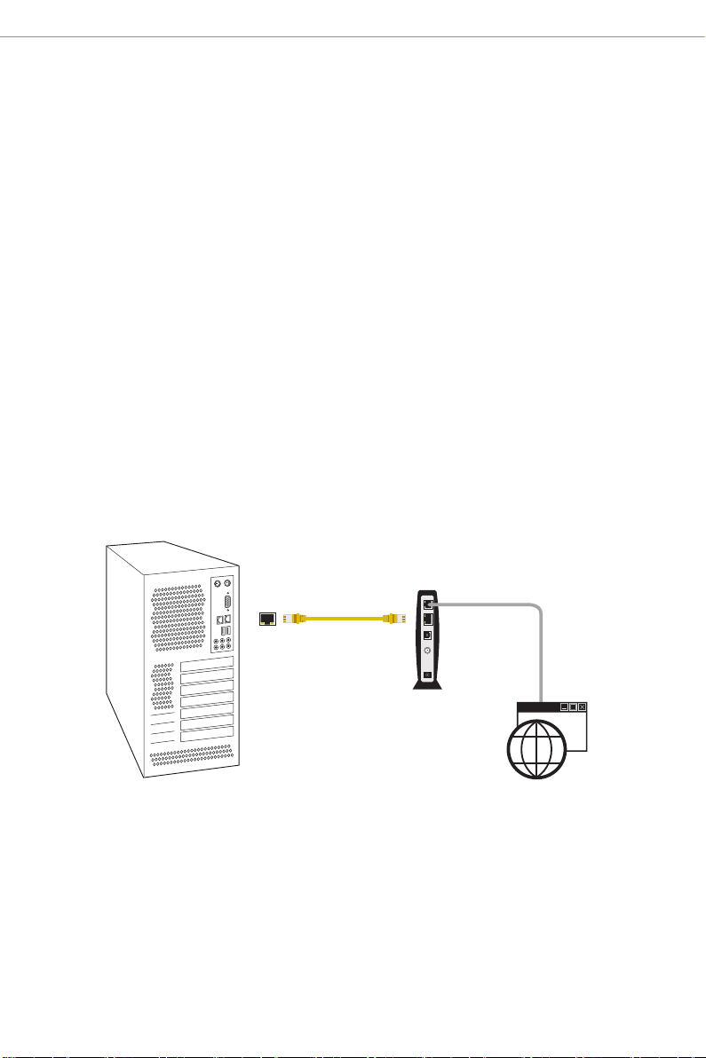
Step 1
Aer you install the Windows OS, connect your computer to the Internet.
RJ-45 Cable
LAN Port
Modem
Internet
2
Page 7
AMD X670/B650 Series
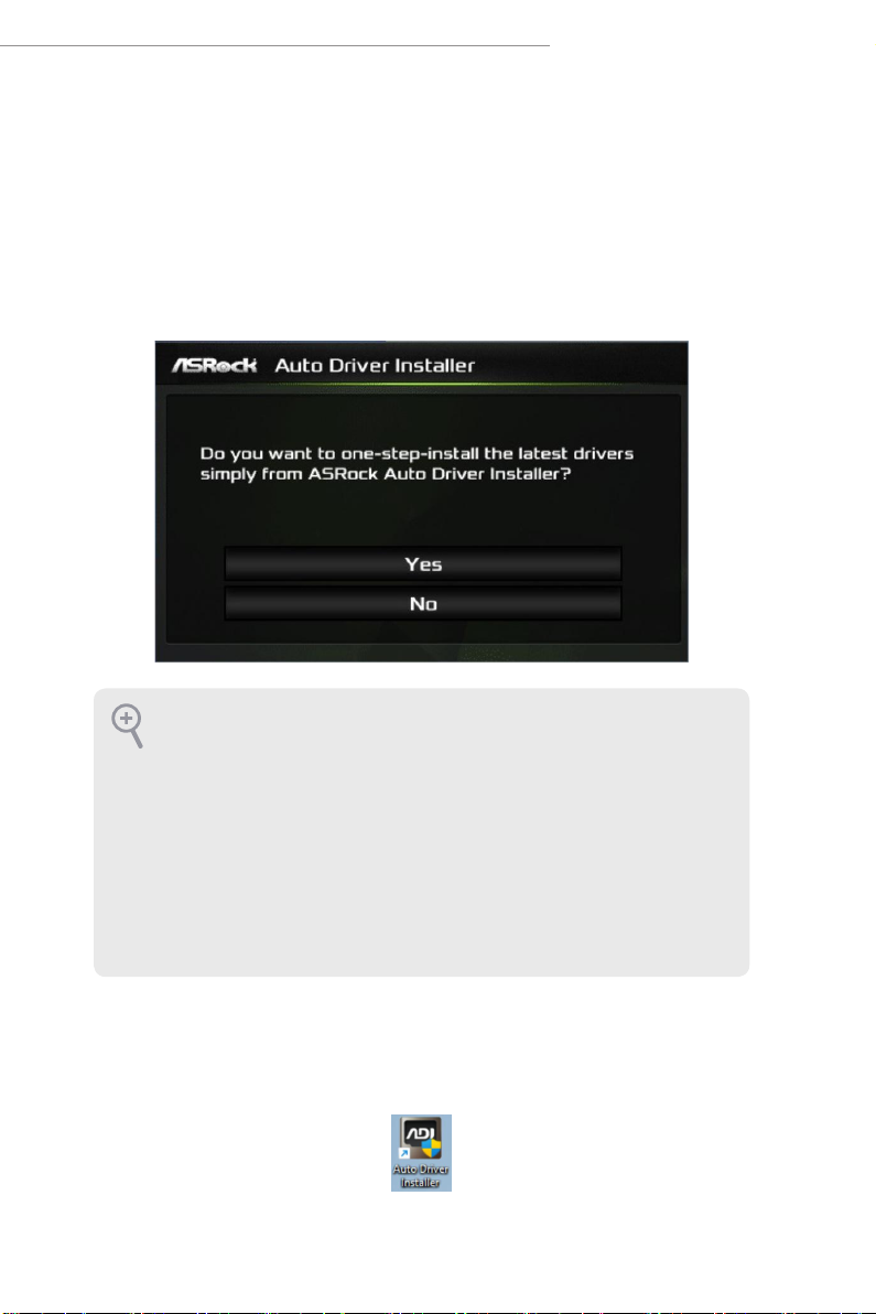
Step 2
Boot into the system, and a notication will pop up in the lower right corner of your
screen saying, "Do you want to one-step-install the latest drivers simply from ASRock
Auto Driver Installer?".
Select “Yes” to install Auto Driver Installer.
Select “No” to skip the installation.
1. e Auto Driver Installer will automatically pop up for users to install dr ivers only
when the “Auto Dr iver Installer“ item under the “Tool“ menu in the BIOS is set to
[Enabled]. e item is enabled by default; therefore, for the r st-time users, there i s
no need to change the setting in the BIOS.
2. An available Internet connection is a prerequisite for u sing the Auto Driver Installer. If you boot into the system without Internet, the Auto Dr iver Installe r won’t
appear. Now connect your computer to the Internet, wait a few seconds, and then
the Auto Dr iver Installe r will pop up.
3. If you sele ct “No“ in Step 2 and skip the insta llation, the Auto Driver Installer will
be remove d. If you would like to run the application again, pl ease enable the “Auto
Driver Installe r“ item in the BIOS setting.
Step 3
When it's completed, you will see the Auto Driver Installer icon on your desktop and then
the Auto Driver Installer appears.
3
Page 8
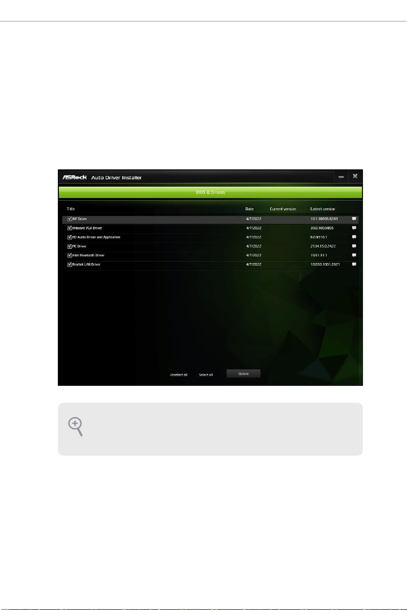
Step 4
e Auto Driver Installer panel lists all available drivers that your motherboard supports.
Select one or more drivers to be installed.
Click "Select All" to select all items.
Click "Unselect All" to remove all of your selections.
Click "Update" to start downloading and installing drivers.
If there are no drivers to be installed, click “Finish” to exit. If you would like to run
the application again, please enable the “Auto Drive r Installer“ item in the BIOS
sett ing.
4
Page 9
AMD X670/B650 Series
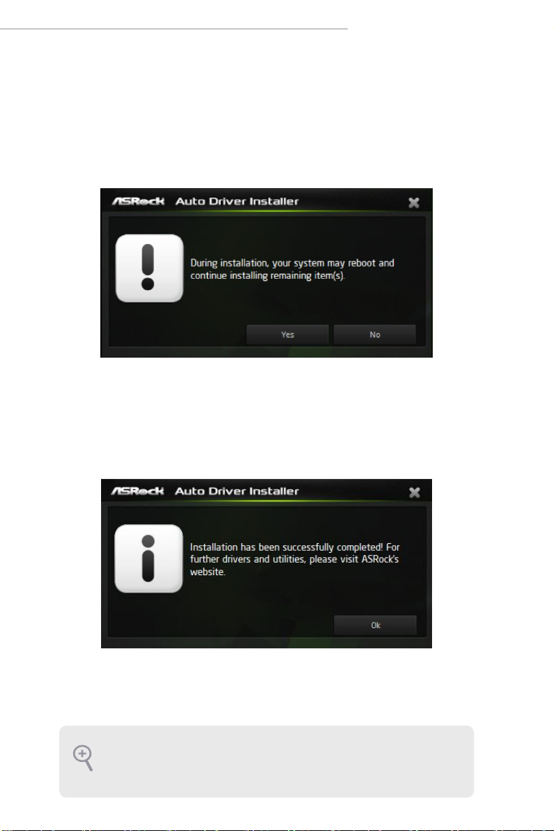
Step 5
A messages pops up saying, "During installation, your system may reboot and continue
installing remaining item(s)".
Click "Yes" to continue.
Click “No” to exit.
Step 6
Once all drivers are successfully installed, a message pops up saying, "Installation has
been successfully completed! For further drivers and utilities, please visit ASRock's
website."
Click "Ok " to complete the procedure.
When driver installation is completed, the Auto Driver Installer tool will be uninstalled
automatically from your computer.
Aer driver installation, the Auto Drive r Installer will be removed. If you would like
to run the application again, please go to the “ Tool“ menu in the BIOS setting, and
set the “Auto Driver Installer“ item to [Enabled].
5
Page 10
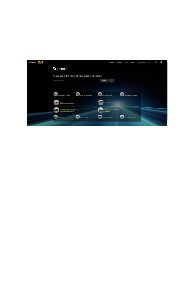
2.1.2 Updating Drivers
Updating drivers ensures that your system work well without any issue. To update drivers,
please go to ASRock' website (https://ww w.asrock.com) and select "Support" > "Latest
Drivers Update".
6
Page 11
AMD X670/B650 Series
2.2 ASRock Live Update & APP Shop
e ASRock Live Update & APP Shop is an online store for purchasing and
downloading soware applications for your ASRock computer. You can quick ly and
easily install various apps and support utilities. With ASRock Live Update & APP
Shop, you can optimize your system and keep your motherboard up to date simply
with a few clicks.
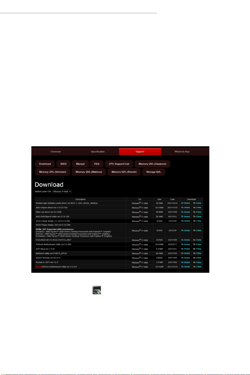
2.2.1 Installing ASRock Live Update & APP Shop
Please download the ASRock Live Update & APP Shop utility from the ASRock's
website: " https://www.asro ck .com".
Go to the product page of your motherboard, select "Support" > "Download" to
download the APP Shop.
Aer installation, double-click on your desktop to access ASRock Live Update
& APP Shop utility.
*You need to be connected to the Internet to d ownload apps from the ASRock Live Update & APP Shop.
7
Page 12
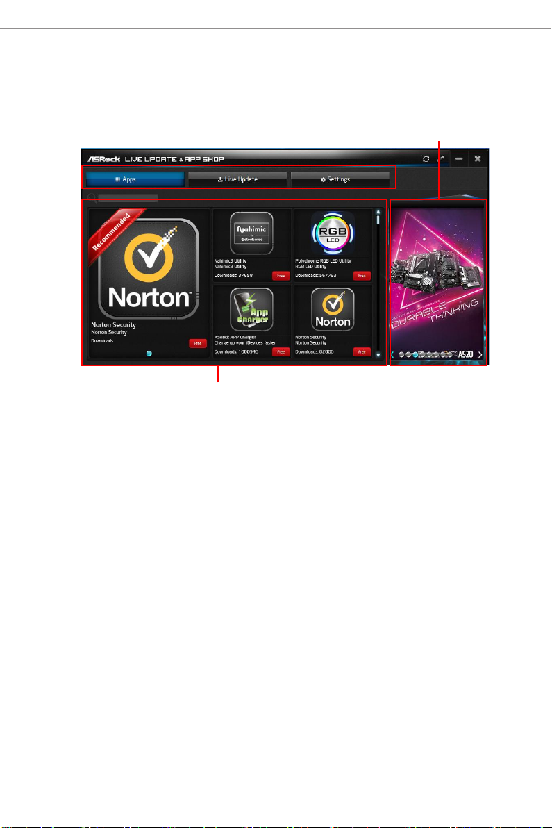
2.2.2 UI Overview
Category Panel
Information Panel
Category Panel: e category panel contains several category tabs or buttons that
when selected the information panel below displays the relative information.
Information Panel: e information panel in the center displays data about the
currently selected category and allows users to perform job-related tasks.
Hot News: e hot news section displays the various latest news. Click on the image
to visit the website of the selected news and know more.
Hot News
8
Page 13
AMD X670/B650 Series
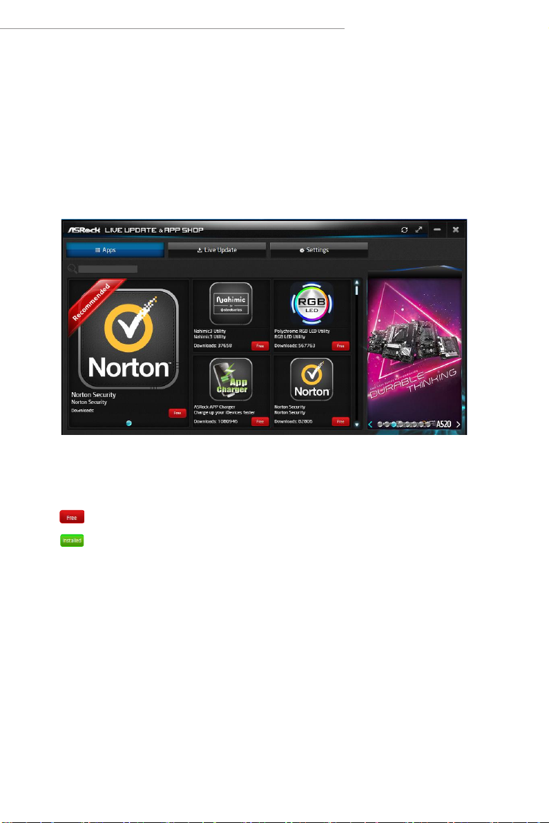
2.2.3 Apps
When the "Apps" tab is selected, you will see all the available apps on screen for you
to download.
Installing an App
Step 1
Find the app you want to insta ll.
e most recommended app appears on the le side of the screen. e other various
apps are shown on the right. Please scroll up and down to see more apps listed.
You can check the price of the app and whether you have already intalled it or not.
- e red icon displays the price or "Free" if the app is free of charge.
- e green "Installed" icon means the app is installed on your computer.
Step 2
Click on the app icon to see more details about the selected app.
9
Page 14
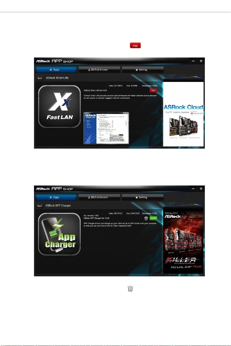
Step 3
If you want to install the app, click on the red icon to start downloading.
Step 4
When installation completes, you can nd the green "Installed" icon appears on the
upper right corner.
To uninstall it, simply click on the trash can icon .
*e trash icon may not appear for certain apps.
10
Page 15
AMD X670/B650 Series
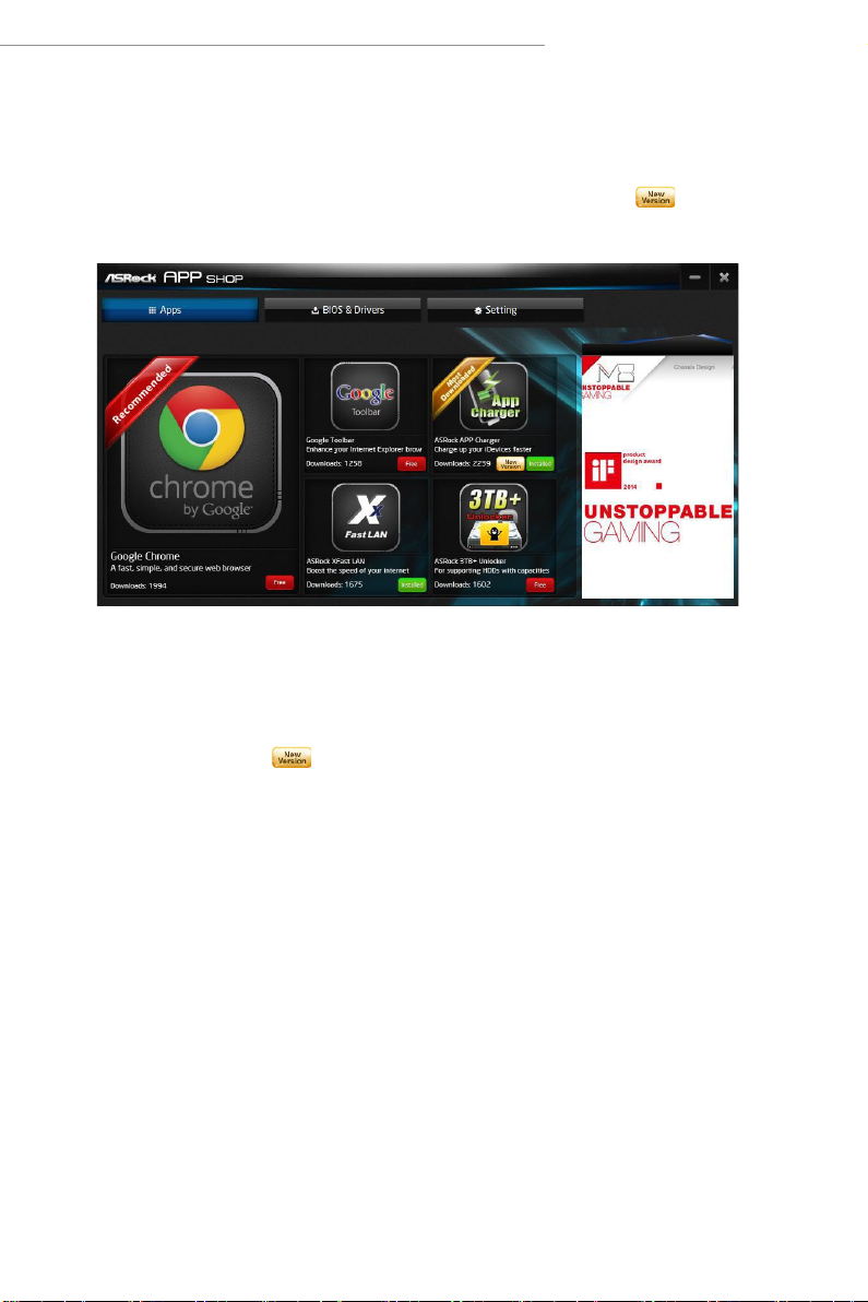
Upgrading an App
You can only upgrade the apps you have already installed. When there is an
available new version for your app, you will nd the mark of "New Version"
appears below the installed app icon.
Step 1
Click on the app icon to see more details.
Step 2
Click on the yellow icon to start upgrading.
11
Page 16
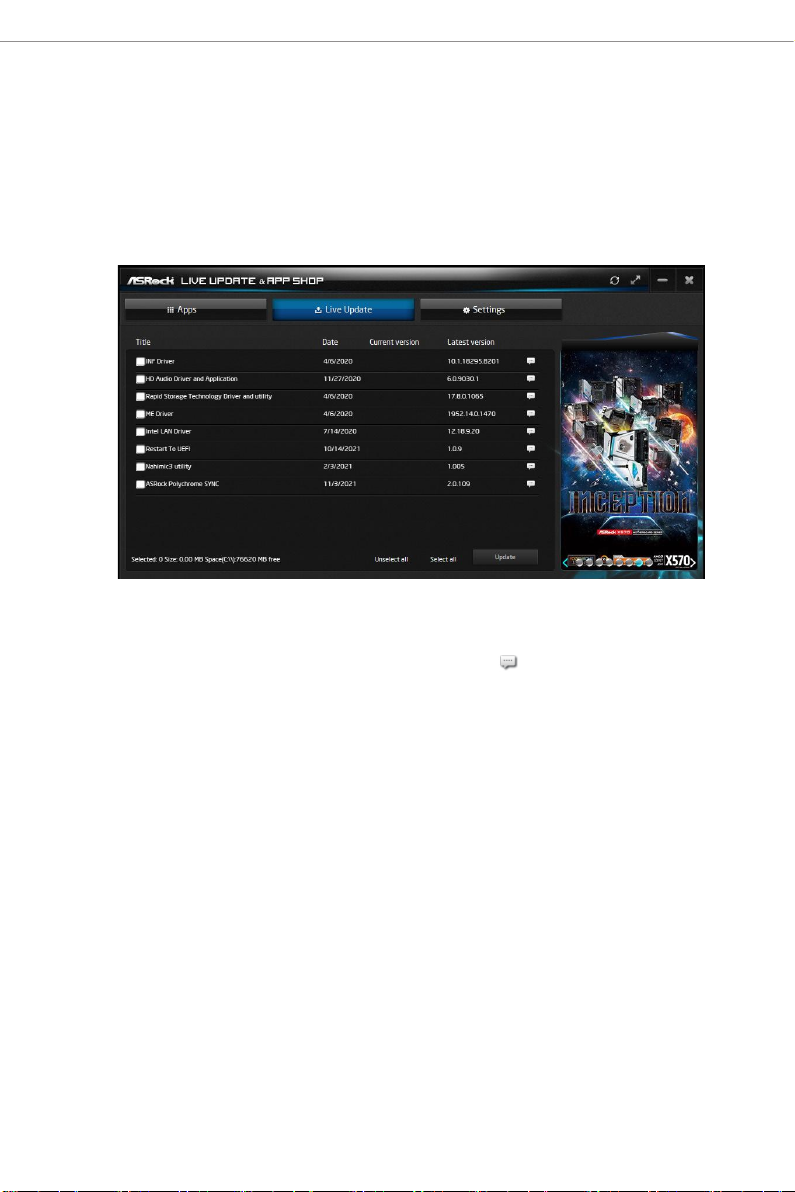
2.2.4 BIOS & Drivers
Installing BIOS or Drivers
When the "BIOS & Drivers" tab is selected, you will see a list of recommended or
critical updates for the BIOS or drivers. Please update them all soon.
Step 1
Please check the item information before update. Click on to see more details.
Step 2
Click to select one or more items you want to update.
Step 3
Click Update to start the update process.
12
Page 17
AMD X670/B650 Series
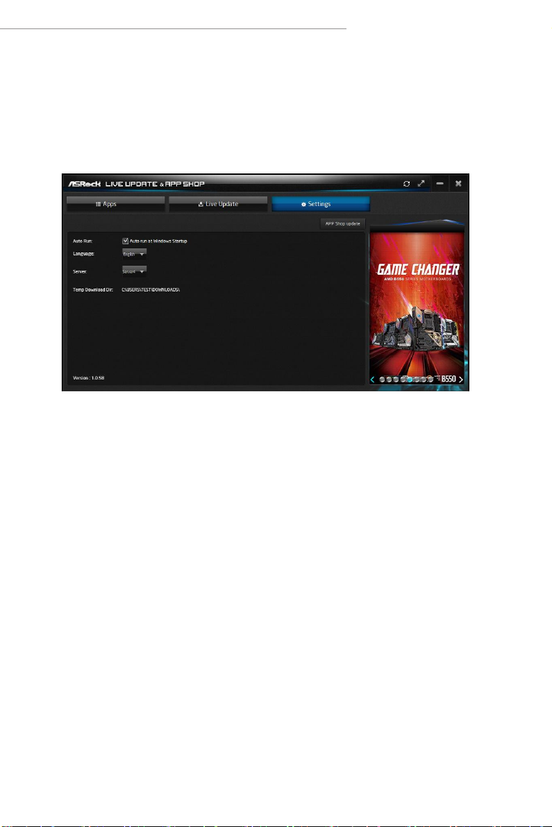
2.2.5 Setting
In the "Setting" page, you can change the language, select the server location, and
determine if you want to automatically run the ASRock Live Update & APP Shop
on Windows startup.
13
Page 18
2.3 ASRock Motherboard Utility (A-Tuning)
ASRock Motherboard Utility (A-Tuning) is ASRock’s multi purpose soware suite
with a new interface, more new features and improved utilities.
2.3.1 Installing ASRock Motherboard Utility (A-Tuning)
ASRock Motherboard Utility (A-Tuning) can be downloaded from ASRock Live
Update & APP Shop.
You can also download the utility from the ASRock 's website: "https://www.asrock.com".
Go to the product page of your motherboard, select "Support" > "Download" to download
"ASRock Motherboard Utility".
Aer the installation, you will nd the icon “ASRock Motherboard Utility (A-
Tuni ng)“ on your desktop. Double-click the
“ASRock Motherboard Utility (A-Tuning)“ icon , ASRock Motherboard Utility
(A-Tuni ng) main menu will pop up.
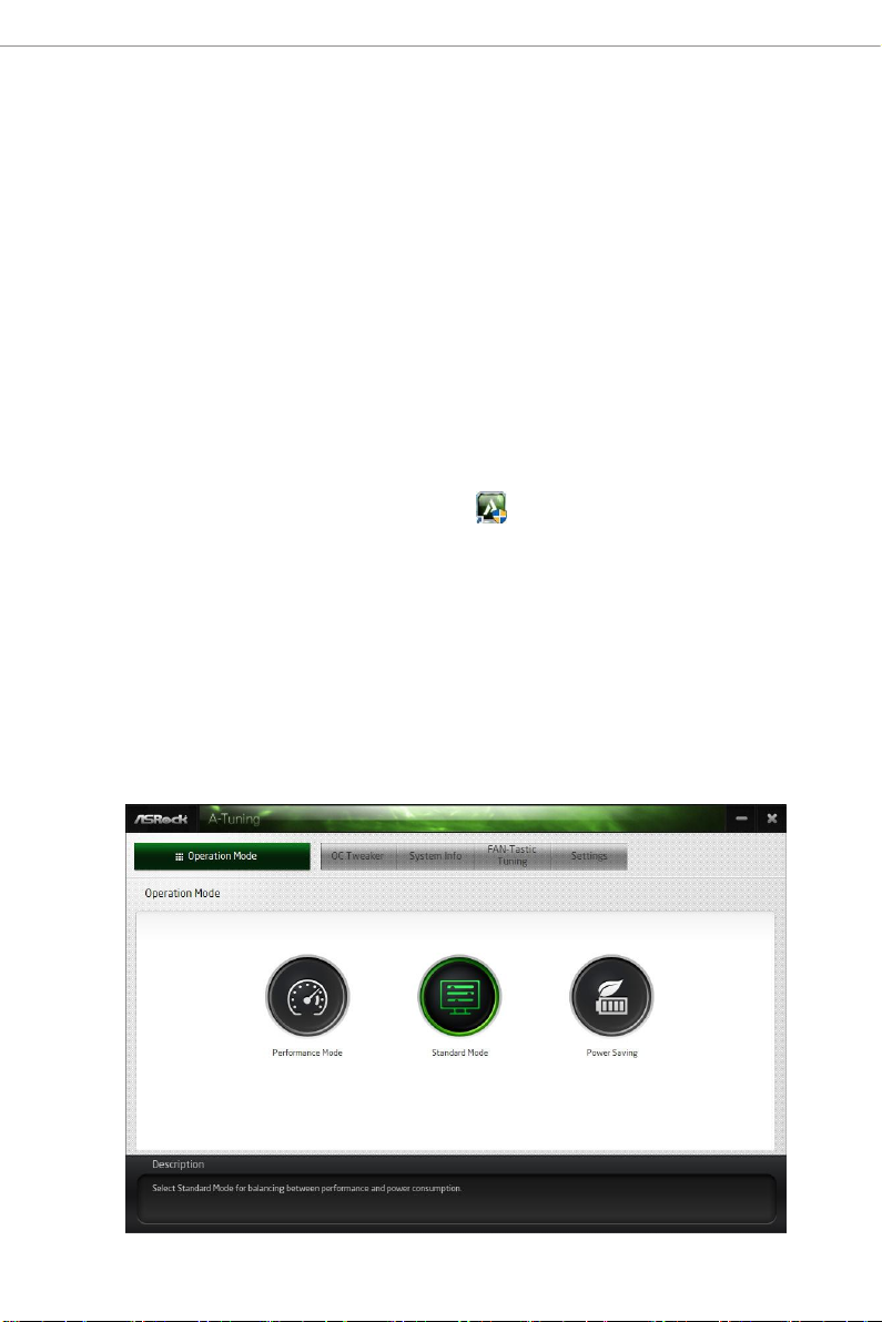
2.3.2 Using ASRock Motherboard Utility (A-Tuning)
ere are ve sections in ASRock Motherboard Utility (A-Tuning) main menu:
Operation Mode, OC Tweaker, System Info, FAN-Tastic Tuning and Settings.
Operation Mode
Choose an operation mode for your computer.
14
Page 19
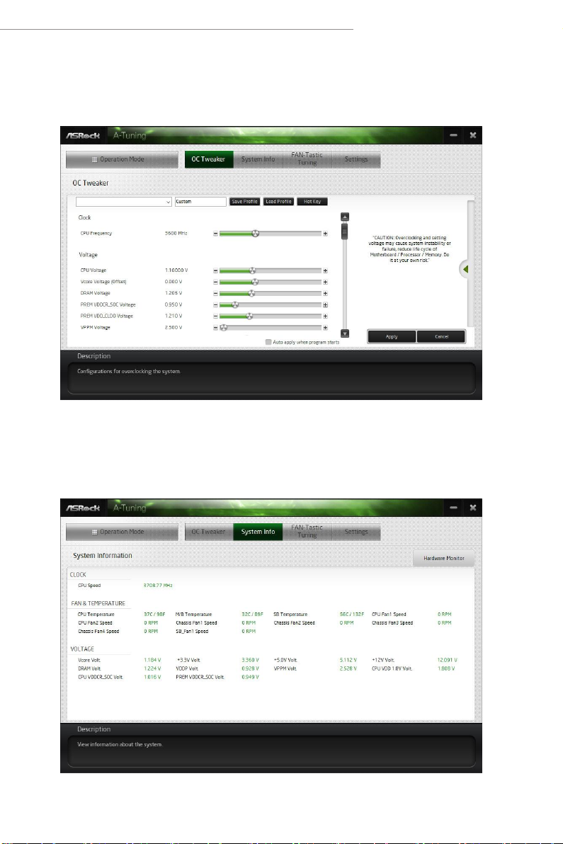
OC Tweake r
Congurations for overclocking the system.
AMD X670/B650 Series
System Info
View information about the system.
*e System Browser tab may not appear for certain models.
15
Page 20
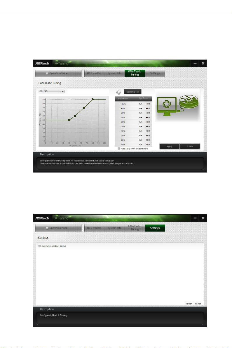
FAN-Tastic Tuning
Congure up to ve dierent fan speeds using the graph. e fans will automatically shi
to the next speed level when the assigned temperature is met.
Settings
Congure ASRock ASRock Motherboard Utility (A-Tuning). Click to select "Auto
run at Windows Startup" if you want ASRock Motherboard Utility (A-Tuning) to
be launched when you start up the Windows operating system.
16
Page 21
AMD X670/B650 Series
2.4 ASRock Motherboard Utility (Phantom Gaming Tuning)
ASRock Motherboard Utility (Phantom Gaming Tuning) is ASRock’s multi pur-
pose soware suite with a new interface, more new features and improved utilities.
2.4.1 Installing ASRock Motherboard Utility (Phantom
Gaming Tuning)
ASRock Motherboard Utility (Phantom Gaming Tuning) can be downloaded from
ASRock Live Update & APP Shop.
You can also download the utility from the ASRock 's website: "https://www.asrock.com".
Go to the product page of your motherboard, select "Support" > "Download" to download
"ASRock Motherboard Utility".
Aer the installation, you will nd the icon “Phantom Gaming Tuning“ on your
desktop. Double-click the “Phantom Gaming Tuning“ icon, Phantom Gaming
Tuning main menu will pop up.
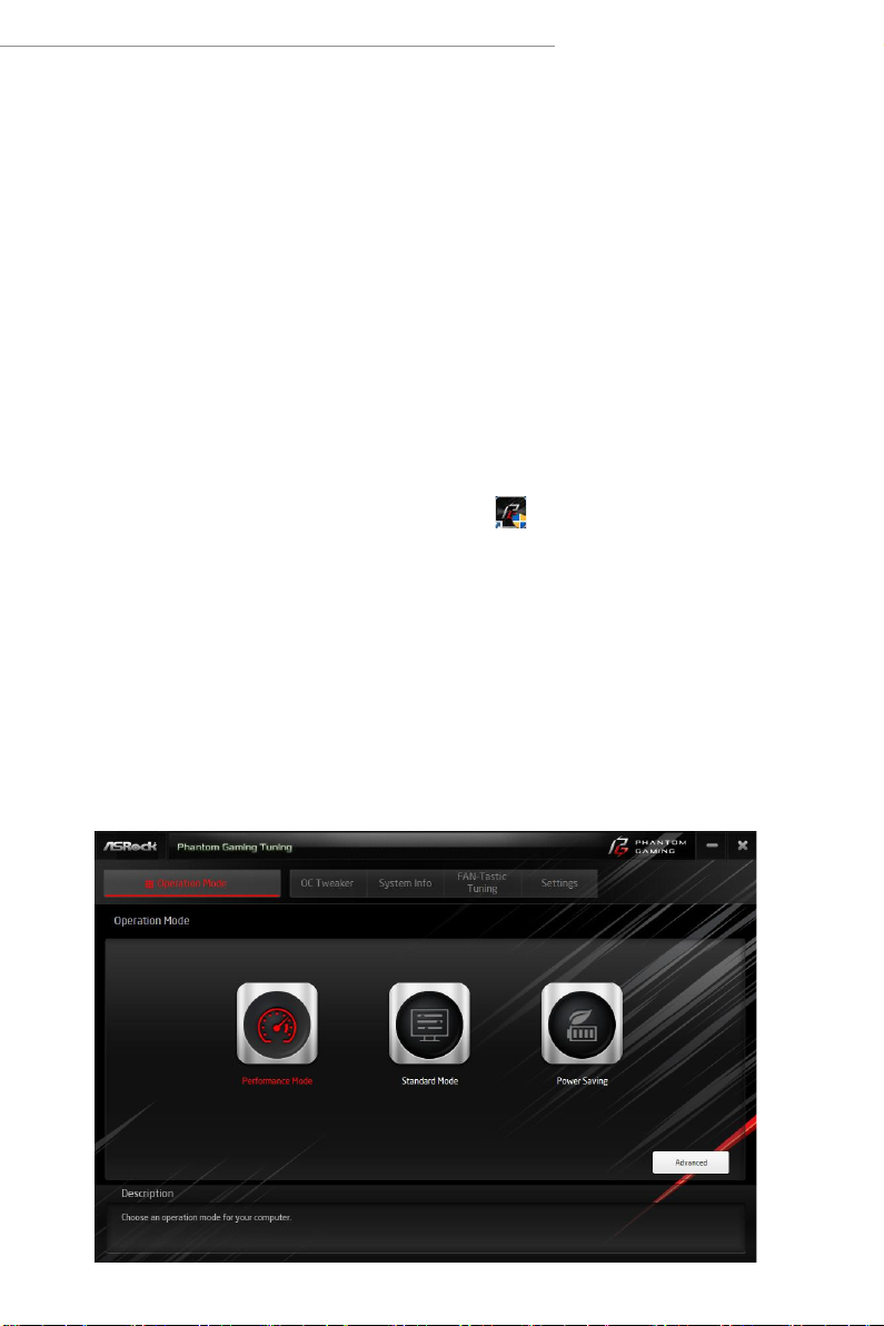
2.4.2 Using ASRock Motherboard Utility (Phantom
Gaming Tuning)
ere are ve sections in ASRock Motherboard Utility (Phantom Gaming Tuning)
main menu: Operation Mode, OC Tweaker, System Info, FAN-Tastic Tuning and
Settings.
Operation Mode
Choose an operation mode for your computer.
17
Page 22
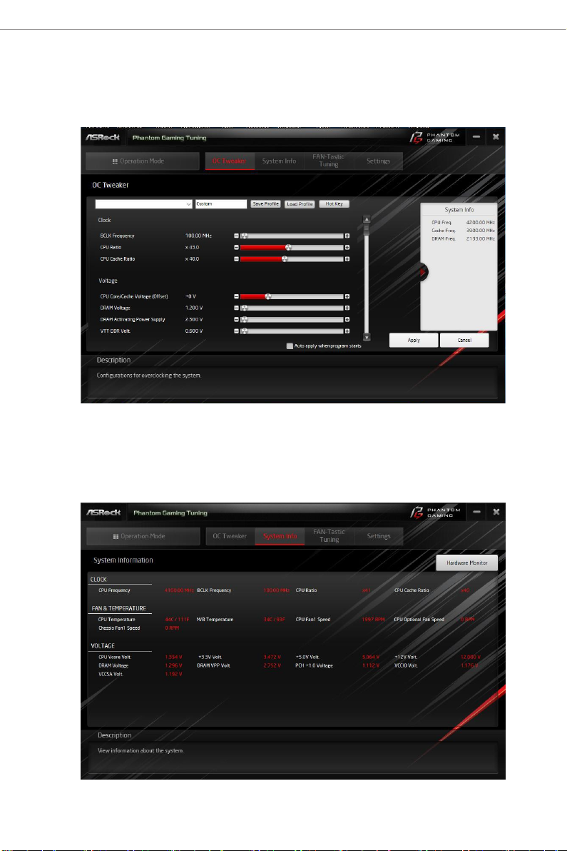
OC Tweake r
Congurations for overclocking the system.
System Info
View information about the system.
*e System Browser tab may not appear for certain models.
18
Page 23
AMD X670/B650 Series
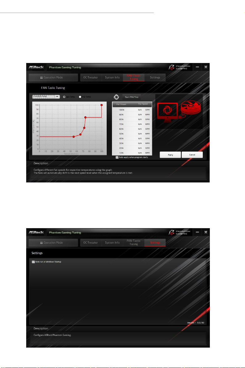
FAN-Tastic Tuning
Congure up to ve dierent fan speeds using the graph. e fans will automatically shi
to the next speed level when the assigned temperature is met.
Settings
Congure ASRock Phantom Gaming Tuning. Click to select "Auto run at Windows
Startup" if you want Phantom Gaming Tuning to be launched when you start up the
Windows operating system.
19
Page 24
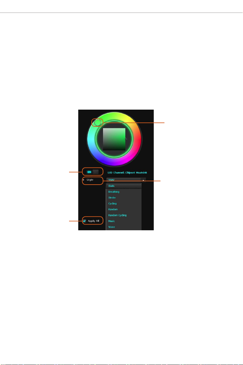
2.5 ASRock Polychrome SYNC
ASRock Polychrome SYNC is a lighting control utility specically designed for unique
individuals with sophisticated tastes to build their own stylish colorful lighting system.
Simply by connecting the LED strip, you can customize various lighting schemes and
patterns, including Static, Breathing, Strobe, Cycling, Music, Wave and more.
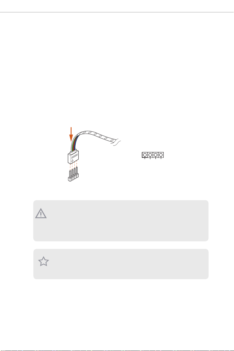
2.5.1 Connecting the LED Strip
Connect your RGB LED strip to the
1
B
R
G
V
2
1
1. Never install the RGB LED cable in the wrong orientation; otherwi se, the cable may be
damaged.
2. Before installing or removing your RGB LED cable, please power o your s ystem and
unplug the power cord from the power supply. Failure to d o so may cause damages to
motherboard components.
1. Please note that the RGB LED strips do not come with the package.
2. e RGB LED header supports stan dard 5050 RGB LED strip (12V/G/R/B), with a
maximum power rating of 3A (12V) and length w ithin 2 meters.
RGB LED Header
on the motherboard.
1
12V GR B
RGB LED Header
20
Page 25
AMD X670/B650 Series
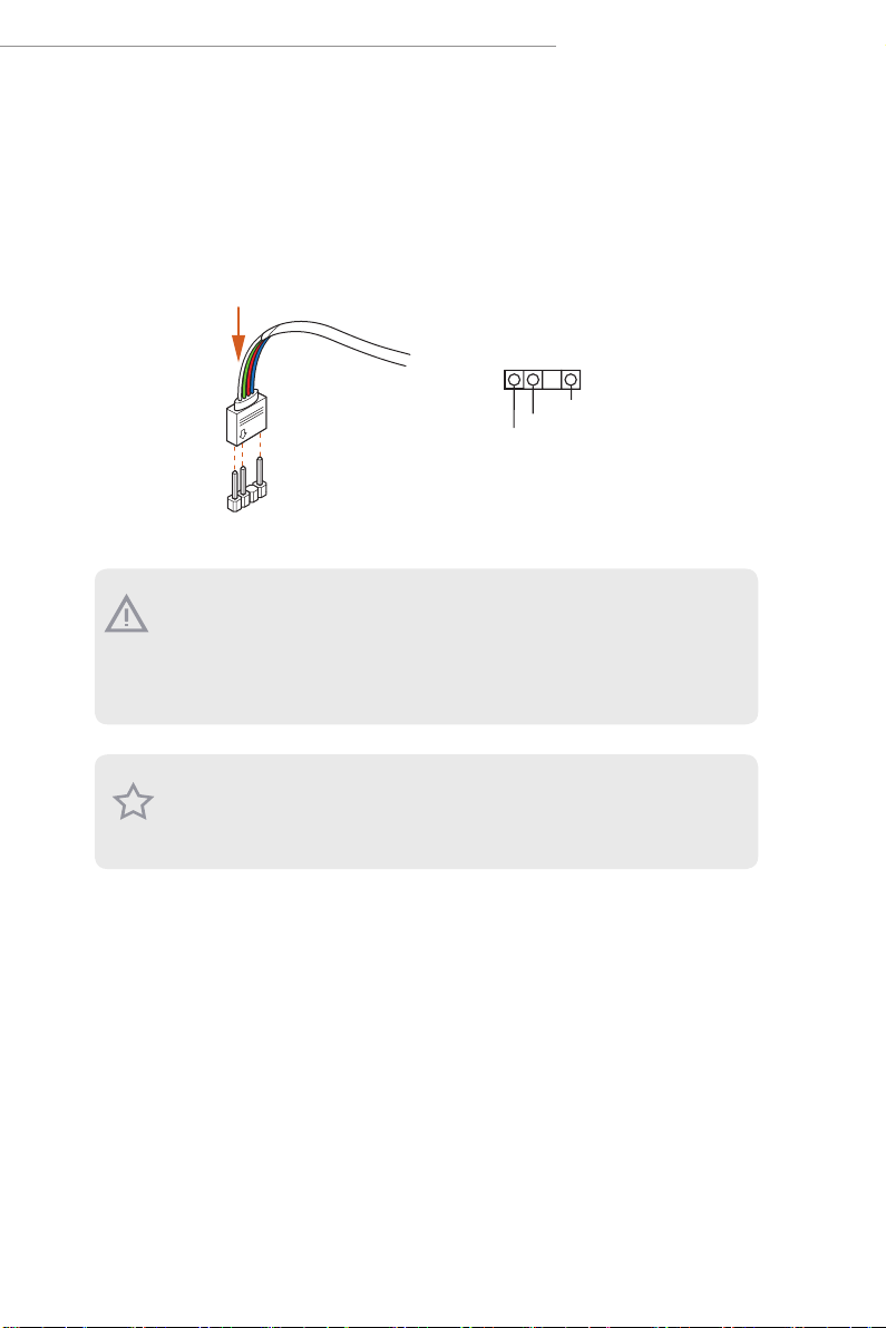
2.5.2 Connecting the Addressable RGB LED Strip
Connect your
motherboard.
1. Never install the RGB LED cable in the wrong orientation; otherwi se, the cable may be
damaged.
2. Before installing or removing your RGB LED cable, please power o your s ystem and
unplug the power cord from the power supply. Failure to d o so may cause damages to
motherboard components.
1. Please note that the RGB LED strips do not come with the package.
2. e RGB LED header supports WS2812B ad dressable RGB LED strip (5V/Data/
Addressable RGB LED
strip to the
Addressable LED Header
1
GND
DO_ADDR
VOUT
Addressable LED Header
1
GND), with a ma ximum power rating of 3A (5V) and leng th within 2 meters.
on the
21
Page 26
2.5.3 Installing ASRock Polychrome SYNC Utility
Aer connecting the required LED strips, download the ASRockPolychrome SYNC Utility
from the ASRock Live Update & APP Shop. You can also download the utility from the
ASRock's website: "https://www.asrock.com". Go to the product page of your motherboard,
select "Support" > "Download" to download the ASRock Polychrome RGB.
Now you can adjust the RGB LED color through this utility and start coloring your PC
style your way!
Drag the tab to customize your
preference.
Toggle on/o the
RGB LED switch
Sync RGB LED eects
for all LED regions of
the motherboard
Select a RGB LED light eect
from the drop-down menu.
22
Page 27

AMD X670/B650 Series
2.6 Nahimic Audio
Nahimic audio soware provides an incredible high denition sound technology which
boosts the audio and voice performance of your system. Nahimic Audio interface is
composed of four tabs: Audio, Microphone, Sound Tracker and Settings.
Download this utility from the ASRock Live Update & APP Shop. You can also download
the utility from the ASRock's website: "https://www.asrock.com". Go to the product page of
your motherboard, select "Support" > "Download " to download the Nahimic utility.
ere are four functions in Nahimic audio:
No. Function Description
From this tab, you can mute the current audio device, choose
1
Audio
between four factory audio proles, turn all audio eects
on/o, restores the current prole to its default settings and
access Surround Sound and various features.
From this tab, you can mute the current mic device, choose
2
Microphone
between two factory mic proles, turn/o all microphone
eects, restore the current prole to its default settings, and
access Static Noise Suppression and various features.
e Sound Tracker provides a visual indication localizing
the sources of the sounds while in a game. ese are
Sound Tracker
3
represented by dynamic segments pointing the direction
of the sounds: the more opaque they are, the stronger the
sounds are.
23
Page 28

Settings
4
From this tab, you can access all settings and information of
the soware.
24
Page 29

AMD X670/B650 Series
Chapter 3 UEFI SETUP UTILITY
3.1 Introduction
ASRock UEFI (Unied Extensible Firmware Interface) is a BIOS utility which oers twea k-
friendly options in an advanced viewing interface. e UEFI system works with a USB
mouse and oers users a faster, sleeker experience.
is BIOS utility can perform the Power-On Self-Test (POST) during system startup,
record hardware parameters of the system, load operating system, and so on. e battery on
the motherboard supplies the power needed to the CMOS when the system power is turned
o, and the values congured in the UEFI utility are kept in the CMOS.
Please note that inadequate BIOS settings may cause system instability, mulfunction or
boot failure. We strongly recommend that you do not alter the UEFI default congurations
or change the settings only with the assistance of a trained service person.
If the system becomes unstable or fails to boot aer you change the setting, try to clear
the CMOS values and reset the board to default values. See your motherboard manual for
instructions.
3.1.1 Entering BIOS Setup
You may run the UEFI SETUP UTILITY by pressing <F2> or <Del> right aer you power
on the computer; otherwise, the Power-On-Self-Test (POST) will continue with its test
routines. If you wish to enter the UEFI SETUP UTILITY aer POST, restart the system by
pressing <Ctl> + <Alt> + <Delete>, or by pressing the reset button on the system chassis.
You may also restart by turning the system o and then back on.
is setup guide explains how to use the UEFI SETUP UTILITY to congure all the
supported system. e screenshots in this manual are for reference only. UEFI Settings and
options may vary owing to dierent BIOS release versions or CPU installed. Please refer to
the actual BIOS version of the motherboard you purchased for detailed screens, settings
and options.
25
Page 30

3.1.2 UEFI Menu Bar
e top of the screen has a menu bar with the following selections:
Main
OC Tweaker
Advanced
Tool
H/W Monitor
Security
Boot
Exit
Becau se the UEFI soware is constantly being updated, the following U EFI setup
screens and desc riptions for reference purpose only, and may vary from the latest
BIOS and do not exactly match what you se e on your screen.
For setting system time/date information
For overclocking congurations
For advanced system congurations
Useful tools
Displays current hardware status
For security settings
For conguring boot settings and boot priority
Exit the current screen or the UEFI Setup Utility
26
Please realize that there is a certain risk involved with overclocking, including
adjusting the setting in the BIOS, applying Untied Overclo cking Technology, or using
third-party overclocking tools. Overclocking may aect your system’s stability, or
even cause damage to the components and devices of your system. It should be done
at your own risk and expense. We are not responsible for possible damage caused b y
overclocking.
Page 31

AMD X670/B650 Series
3.1.3 Navigation Keys
Use < > key or < > key to choose among the selections on the menu bar, and
use < > key or < > key to move the cursor up or down to select items, then
press <Enter> to get into the sub screen. You can also use the mouse to click your
required item.
Please check the following table for the descriptions of each navigation key.
Navigation Key(s) Description
+ / -
<Tab>
<PGUP>
<PGDN>
<HOME>
<END>
<F1>
<F7>
<F9>
<F10>
<F12>
<ESC>
To change option for the selected items
Switch to next function
Go to the previous page
Go to the next page
Go to the top of the screen
Go to the bottom of the screen
To display the General Help Screen
Discard changes and exit the SETUP UTILITY
Load optimal default values for all the settings
Save changes and exit the SETUP UTILITY
Print screen
Jump to the Exit Screen or exit the current screen
27
Page 32

3.2 Main Screen
When you enter the UEFI SETUP UTILITY, the Main screen will appear and
display the system overview.
Becau se the UEFI soware is constantly being updated, the following U EFI setup
screens and desc riptions are for refere nce purpose only, and they may not exactly
match what you see on your screen. Options may al so vary depending on the features
of your motherboard.
28
Page 33

3.3 OC Tweaker Screen
In the OC Tweaker screen, you can set up overclocking features.
AMD X670/B650 Series
BCLK Conguration
Press [Enter] to congure BCLK options.
BCLK Frequency
e CPU speed is determined by the CPU Ratio multiplied with the BCLK. Increasing the
BCLK will increase the internal CPU clock speed but also aect the clock speed of other
components.
BCLK SSC Mode
Allows you to select the BCLK Spread Spectrum Mode.
Conguration options: [Auto] [Disabled] [Down Spreading 0.10%] [Down Spreading
0.25%] [Down Spreading 0.50%] [Center Spreading 0.10%] [Center Spreading 0.25%]
[Center Spreading 0.50%]
BCLK Frequency F0D1
e CPU speed is determined by the CPU Ratio multiplied with the BCLK. Increasing the
BCLK will increase the internal CPU clock speed but also aect the clock speed of other
components.
29
Page 34

F0D1 SSD Mode
Allows you to select the BCLK Spread Spectrum Mode.
Conguration options: [Auto] [Disabled] [Down Spreading 0.10%] [Down Spreading
0.25%] [Down Spreading 0.50%] [Center Spreading 0.10%] [Center Spreading 0.25%]
[Center Spreading 0.50%]
Spectrum Spreading Share
When two SSC engines have the same modulation frequency, setting this bit to 1 will align
the phase of F0D1 SSC to F0D0 SSC.
Conguration options: [Auto] [Disabled] [Enabled]
CPU Overclocking
Allows you to congure CPU overclocking settings.
[Auto] Select this item to apply the default BCLK Delay setting.
[Customize] Select this item to customize BCLK Delay setting.
DRAM Frequency
If [Auto] is selected, the motherboard will detect the memory module(s) inserted
and assign the appropriate frequency automatically.
DRAM Prole
Loads XMP settings to overclock the DDR5 memory and perform beyond standard
specications.
DRAM Timing Conguration
Allows you to congure DRAM Timing.
CAS# Latency (tCL)
e time between sending a column address to the memor y and the beginning of the data
in response.
RAS# to CAS# Delay to Read (tRCDRD)
e number of clock cycles required between the opening of a row of memory and
accessing columns within it.
Row Precharge Time (tRP)
e number of clock cycles required between the issuing of the precharge command and
opening the next row.
30
Page 35

AMD X670/B650 Series
RAS# Active Time (tRAS)
e number of clock cycles required between a bank active command and issuing the
precharge command.
RAS# Cycle Time (tRC)
e number of memor y clock cycles from activate command to another activate command.
Write Recovery Time (tWR)
e amount of delay that must elapse aer the completion of a valid write operation,
before an active bank can be precharged.
Refresh Cycle Time (tRFC1)
Species the Refresh Recovery Delay Time.
Refresh Cycle Time (tRFC2)
Species the Refresh Recovery Delay Time.
Refresh Cycle Time (tRFCSb)
Species the Refresh Recovery Delay Time.
Read to Precharge (tRTP)
e number of clocks that are inserted between a read command to a row pre-charge
command to the same rank.
RAS to RAS Delay (tRRD_L)
e number of clocks between two rows activated in dierent banks of the same rank.
RAS to RAS Delay (tRRD_S)
e number of clocks between two rows activated in dierent banks of the same rank.
Four Activate Window (tFAW)
Species the time window in which four activates are allowed the same rank.
Write to Read Delay (tWTR_L)
e number of clocks between the last valid write operation and the next read
command to the same internal bank.
Write to Read Delay (tWTR_L)
e number of clocks between the last valid write operation and the next read
command to the same internal bank.
31
Page 36

TrdrdScL
e minimum number of cycles from the last clock of virtual CAS of the rst read-
burst operation to the clock in which CAS is asserted for a following read-burst
operation in the same chipselect in the same bank group.
TrdrdSc
e minimum number of cycles from the last clock of virtual CAS of the rst read-
burst operation to the clock in which CAS is asserted for a following read-burst
operation in the same chipselect.
TrdrdSd
e minimum number of cycles from the last clock of virtual CAS of the rst read-
burst operation to the clock in which CAS is asserted for a following read-burst
operation in the same DIMM.
TrdrdDd
e minimum number of cycles from the last clock of virtual CAS of the rst read-
burst operation to the clock in which CAS is asserted for a following read-burst
operation in a dierent DIMM.
TwrwrScL
e minimum number of cycles from the last clock of virtual CAS of a rst write-
burst operation to the clock in which CAS is asserted for a following write-burst
operation in the same bank group.
TwrwrSc
e minimum number of cycles from the last clock of virtual CAS of the rst write-
burst operation to the clock in which CAS is asserted for a following write-burst
operation in the same chipselect.
TwrwrSd
e minimum number of cycles from the last clock of virtual CAS of the rst write-
burst operation to the clock in which CAS is asserted for a following write-burst
operation in the same DIMM.
TwrwrDd
e minimum number of cycles from the last clock of virtual CAS of the rst write-
burst operation to the clock in which CAS is asserted for a following write-burst
operation in a dierent DIMM.
32
Page 37

AMD X670/B650 Series
Twrrd
e minimum number of cycles from the last clock of virtual CAS of the rst write-
burst operation to the clock in which CAS is asserted for a following read-burst
operation.
Trdwr
e minimum number of cycles from the last clock of virtual CAS of the rst read-
burst operation to the clock in which CAS is asserted for a following write-burst
operation.
DRAM Bus Control Conguration
Press [Enter] to congure DRAM Bus Control options.
Power Down Enable
Allows you to enable or disable DDR5 power down mode.
Conguration options: [Auto] [Disabled] [Enabled]
Dram ODT impedance RTT_NOM_RD
Allows you to specify the Dram ODT impedance RTT_NOM_RD.
Conguration options: [Auto] [RTT_OFF] [RZQ (240)] [RZQ/2 (120)] [RZQ/3 (80)]
[RZQ/6 (60)] [RZQ/5 (48)] [RZQ/6 (40)] [RZQ/7 (34)]
Dram ODT impedance RTT_NOM_WR
Allows you to specify the Dram ODT impedance RTT_NOM_WR.
Conguration options: [Auto] [RTT_OFF] [RZQ (240)] [RZQ/2 (120)] [RZQ/3 (80)]
[RZQ/6 (60)] [RZQ/5 (48)] [RZQ/6 (40)] [RZQ/7 (34)]
Dram ODT impedance RTT_WR
Allows you to specify the Dram ODT impedance RTT_WR.
Conguration options: [Auto] [RTT_OFF] [RZQ (240)] [RZQ/2 (120)] [RZQ/3 (80)]
[RZQ/6 (60)] [RZQ/5 (48)] [RZQ/6 (40)] [RZQ/7 (34)]
Dram ODT impedance RTT_PARK
Allows you to specify the Dram ODT impedance RTT_PARK.
Conguration options: [Auto] [RTT_OFF] [RZQ (240)] [RZQ/2 (120)] [RZQ/3 (80)]
[RZQ/6 (60)] [RZQ/5 (48)] [RZQ/6 (40)] [RZQ/7 (34)]
Dram ODT impedance DQS_RTT_PARK
Allows you to specify the Dram ODT impedance DQS_RTT_PARK.
Conguration options: [Auto] [RTT_OFF] [RZQ (240)] [RZQ/2 (120)] [RZQ/3 (80)]
33
Page 38

[RZQ/6 (60)] [RZQ/5 (48)] [RZQ/6 (40)] [RZQ/7 (34)]
Dram DQ drive strengths
Allows you to select the Dram Pull-up and Pull-Down Driver Impedance for all DQ and
DMI IOs.
[Auto] Select this item to apply the default setting.
Processor ODT impedance
Allows you to specify the Processor ODT impedance.
[Auto] Select this item to apply the default setting.
Processor DQ drive strengths
Allows you to specify the Processor DQ drive strengths.
[Auto] Select this item to apply the default setting.
Processor CA drive strengths
Allows you to specify the Processor CA drive strengths.
[Auto] Select this item to apply the default setting.
Innity Fabric Frequency and Dividers
AMD Overclocking Setup Set Innity Fabric frequency (FCLK).
[Auto] FCLK = MCLK.
[Manual] FCLK must be less than or equal to MCLK for the best performance in most cases.
Latency penalties are incurred if FCLK and MCLK are mismatched, but suciently high
MCLK can negate or overcome this penalty.
UCLK DIV1 MODE
Allows you to set UCLK DIV mode.
VDDG CCD Voltage
VDDG CCD represents voltage for the data portion of the Innity Fabric. It is derived
from the CPU SoC/Uncore Voltage (VDD_SOC). VDDG can approach but not exceed
VDD_SOC.
VDDG IOD Voltage
VDDG IOD represents voltage for the data portion of the Innity Fabric. It is derived from
the CPU SoC/Uncore Voltage (VDD_SOC). VDDG can approach but not exceed VDD_
SOC.
34
Page 39

AMD X670/B650 Series
VDDP Voltage
VDDP is a voltage for the DDR bus signaling (PHY), and it is derived from your DRAM
Voltage (VDDIO_Mem). As a result, VDDP voltage can approach but not exceed your DRAM
Volt age.
SoC/Uncore OC Voltage(VID)
Allows you to specify the SoC/Uncore voltage (VDD_SOC) to support memory and Innity
Fabric overclocking. VDD_SOC also determines the GPU voltage on processors with
integrated graphics.
VDD Misc Voltage
Allows you to congure the PCIe, DP Phy, PLL, ClkGen, and Pmux Supply.
DRAM VDDIO Voltage
Use this item to congure the VDDIO Voltage.
Seperate DRAM VDDIO Voltage Control
Allows you to congure the Seperate DRAM VDDIO Voltage control setting.
DRAM VPP Voltage
Allows you to congure the VPP Voltage supportewd by PMIC at DRAM side.
[Auto] Select this item to apply the default setting.
External Voltage Settings
Press [Enter] to congure the voltage options.
VDDCR_CPU Voltage
Input voltage for the processor by the external voltage regulator.
[Auto]
Select this item to apply the default VDDCR_CPU voltage setting.
[Oset Mode]
is mode allows you to congure the VDDCR_CPU voltage oset value.
[Fixed Mode]
is mode allows you to set a xed VDDCR_CPU voltage value.
VDDCR_CPU Load-Line Calibration
Load-Line is dened by Intel VRM Spec and aects the CPU power voltage. CPU Load-
Line Calibration helps prevent CPU voltage droop when the system is under heavy loading.
35
Page 40

Higher load-line (Level 1 or Disable) calibration gets higher voltage and good overclocking
performance but increases the CPU and VRM thermal.
Conguration options: [Auto] [Level1]-[Level5]
VDDCR_CPU Auto Phase
Allows you to congure VDDCR_CPU Auto Phase.
[Enabled] Select this item to enable VDDCR_CPU Auto Phase support.
[Disabled] Select this item to disable VDDCR_CPU Auto Phase support.
VDDCR_CPU Over Voltage Protection
Allows you to congure VDDCR_CPU Over Voltage Protection.
[Enabled] Select this item to enable VDDCR_CPU Over Voltage Protection.
[Disabled] Select this item to disable VDDCR_CPU Over Voltage Protection.
VDDCR_CPU Over Current Protection
Allows you to congure VDDCR_CPU Over Current Protection.
[Enabled] Select this item to enable VDDCR_CPU Over Current Protection
support.
[Disabled] Select this item to disable VDDCR_CPU Over Current Protection
support.
VDDCR_CPU VR_HOT
Allows you to congure VDDCR_CPU VR_HOT.
VDDCR_CPU OTP Mode
[Enabled] Select this item to enable VDDCR_CPU OTP Mode.
[Disabled] Select this item to disable VDDCR_CPU OTP Mode.
VDDCR_CPU OTP Temperature
Allows you to congure VDDCR_CPU OTP Temperature.
VDDCR_SOC Voltage
Input voltage for the processor by the external voltage regulator.
[Auto]
Select this item to apply the default VDDCR_SOC voltage setting.
[Oset Mode]
is mode allows you to congure the VDDCR_SOC voltage oset value.
36
Page 41

AMD X670/B650 Series
[Fixed Mode]
is mode allows you to set a xed VDDCR_SOC voltage value.
VDDCR_SOC Load-Line Calibration
VDDCR_SOC Load-Line Calibration helps prevent CPU voltage droop when the system is
under heavy load.
Conguration options: [Auto] [Level1]-[Level5]
VDDCR_SOC Auto Phase
Allows you to congure VDDCR_SOC Auto Phase.
[Enabled] Select this item to enable VDDCR_SOC Auto Phase support.
[Disabled] Select this item to disable VDDCR_SOC Auto Phase support.
VDDCR_SOC VR_HOT
Allows you to congure VDDCR_SOC VR_HOT.
VDDCR_SOC OTP Mode
[Enabled] Select this item to enable VDDCR_SOC OTP Mode.
[Disabled] Select this item to disable VDDCR_SOC OTP Mode.
VDDCR_SOC OTP Temperature
Allows you to congure VDDCR_SOC OTP Temperature.
VDD_MISC Voltage
Input voltage for the processor by the external voltage regulator.
[Auto]
Select this item to apply the default VDDCR_MISC voltage setting.
[Oset Mode]
is mode allows you to congure the VDDCR_MISC voltage oset value.
[Fixed Mode]
is mode allows you to set a xed VDDCR_MISC voltage value.
VDD_MISC Load-Line Calibration
VDD_MISC Load-Line Calibration helps prevent CPU voltage droop when the system is
under heavy load.
Conguration options: [Auto] [Level 1]-[Level 5]
37
Page 42

VDD_MISC Auto Phase
Allows you to congure VDD_MISC Auto Phase.
[Enabled] Select this item to enable VDD_MISC Auto Phase support.
[Disabled] Select this item to disable VDD_MISC Auto Phase support.
VDD_MISC Over Voltage Protection
Allows you to congure VDD_MISC Over Voltage Protection.
[Enabled] Select this item to enable VDD_MISC Over Voltage Protection.
[Disabled] Select this item to disable VDD_MISC Over Voltage Protection.
VDD_MISC Over Current Protection
Allows you to congure VDD_MISC Over Current Protection.
[Enabled] Select this item to enable VDD_MISC Over Current Protection.
[Disabled] Select this item to disable VDD_MISC Over Current Protection.
VDD_MISC VR_HOT
Allows you to congure VDD_MISC VR_HOT.
VDD_MISC OTP Mode
[Enabled] Select this item to enable VDD_MISC OTP Mode.
[Disabled] Select this item to disable VDD_MISC OTP Mode.
VDD_MISC OTP Temperature
Allows you to congure VDD_MISC OTP Temperature.
VDD_MISC Voltage
Allows you to congure the voltage for the VDD_MISC Voltage.
[Auto]
Select this item to apply the default VDD_MISC voltage setting.
[Oset Mode]
is mode allows you to congure the VDD_MISC voltage oset value.
[Fixed Mode]
is mode allows you to set a xed VDD_MISC voltage value.
38
Page 43

AMD X670/B650 Series
1.8VSB Voltage
Allows you to congure the voltage for the 1.8VSB Voltage.
[Auto] Select this item to apply the default setting.
+1.05V_RUN Voltage
Allows you to congure the voltage for the +1.05V_RUN Voltage.
[Auto] Select this item to apply the default setting.
+1.05V_ALW Voltage
Allows you to congure the voltage for the +1.05V_ALW Voltage.
[Auto] Select this item to apply the default setting.
Save User Default
Type a prole name and press enter to save your settings as user default.
Load User Default
Loads previously saved user defaults.
Save User UEFI Setup Prole to Disk
Saves current UEFI settings as an user default prole to disk.
Load User UEFI Setup Prole to Disk
Loads previously saved user defaults from the disk.
39
Page 44

3.4 Advanced Screen
In this section, you may set the congurations for the following items: CPU
Conguration, PCI Conguration, Onboard Devices Conguration, Storage Con-
guration, ACPI Conguration, Trusted Computing, AMD CBS, AMD PBS and
AMD Overclocking.
Setting wrong values in this section may cause the system to malfun ction.
Active Page on Entry
Allows you to select the default page when entering the UEFI setup utility.
Conguration options: [Main] [OC Tweaker] [Advanced] [Tool] [H/W Monitor]
[Security] [Boot] [Exit]
Full HD UEFI BIOS
[Auto]
When [Auto] is selected, the resolution will be set to 1920 x 1080 if the monitor sup-
ports Full HD resolution. If the monitor does not support Full HD resolution, then
the resolution will be set to 1024 x 768.
[Disabled]
When [Disabled] is selected, the resolution will be set to 1024 x 768 directly.
40
Page 45

AMD X670/B650 Series
3.4.1 CPU Conguration
PSS Support
Allows you to enable or disable the generation of ACPI_PPC, _PSS, and _PCT objects.
NX Mode
Allows you to enable or disable No-execute page protection function.
SVM Mode
When this is set to [Enabled], a VMM (Virtual Machine Architecture) can utilize the
additional hardware capabilities provided by AMD-V. e default value is [Enabled].
Conguration options: [Enabled] and [Disabled].
SMT Mode
is item can be used to disable symmetric multithreading. To re-enable SMT, a
power cycle is needed aer selecting [Auto].
Warning: S3 is not supported on systems where SMT is disabled.
AMD fTPM Switch
Use this to enable or disable AMD CPU fTPM.
Conguration options: [AMD CPU fTPM] [Route to SPI TPM] [Disabled]
41
Page 46

3.4.2 PCI Conguration
Above 4G Decoding
Globally enables or disables 64-bit capable devices to be decoded in Above 4G Address Space
(only if the system supports 64-bit PCI Decoding).
Re-Size BAR Support
If system has Resizable BAR capable PCIe Devices, this option enables or disables Resizable
BAR Support.
Above 4GB MMIO Limit
Allows you to select Above 4GB MMIO Limit to 38~43 bits limit. is option works only
when "Above 4G decoding" is enabled.
Conguration options: [40bit (1TB)] [41bit (2TB)] [42bit (4TB)] [43bit (8TB)]
SR-IOV Support
If system has SR-IOV capable PCIe Devices, this option enables or disables Single Root IO
Virtualization Support.
42
Page 47

3.4.3 Onboard Devices Conguration
Turn On Onboard LED in S5
Allows you to turn on/o the LED in the ACPI S5 state.
AMD X670/B650 Series
[Disabled] Select this item to turn o the LED in the ACPI S5 state.
[Enabled] Select this item to turn on the LED in the ACPI S5 state.
Restore Onboard LED Default
Allows you to restore Onboard LED default value.
[Disabled] Select this item to not to restore Onboard LED default value.
[Apply] Select this item to restore Onboard LED default value.
RGB LED On/O
Allows you to enable or disable the RGB LED.
[On] Select this item to enable the RGB LED.
[O] Select this item to disable the RGB LED.
Integrated Graphics Controller
Allows you to enable or disable integrated graphics controller. When it is set to
[Customize], the UMA Frame buer Size option below appears and is allowed to be
43
Page 48

congured.
Conguration options: [Disabled] [Enabled] [Customize]
UMA Frame buer Size
Disable CSM to get frame buer size more than 2GB. Congure the size of memory
that is allocated to the integrated graphics processor when the system boots up.
[Auto] BIOS will congure this setting automatically.
Onboard HD Audio
Allows you to enable or disable onboard HD audio.
WAN Radio
Allows you to congure the WiFi module's connectivity.
BT On/O
Allows you to enable or disable the bluetooth.
Conguration options: [Auto] [Disabled] [Enabled]
PS2 Y-Cable
Enable the PS2 Y-Cable or set this option to Auto.
PCIe Gen5 redriver
Allows you to enable or disable the PCIe Gen5 redriver.
Downstream High Frequency Peak Port A
Allows you to congure the Downstream High Frequency Peak Port A settings.
Downstream High Frequency Peak Port B
Allows you to congure the Downstream High Frequency Peak Port B settings.
Downstream Low Frequency Peak Port A
Allows you to congure the Downstream Low Frequency Peak Port A settings.
Downstream Low Frequency Peak Port B
Allows you to congure the Downstream Low Frequency Peak Port B settings.
Upstream High Frequency Peak Port A
Allows you to congure the Upstream High Frequency Peak Port A settings.
44
Page 49

AMD X670/B650 Series
Upstream High Frequency Peak Port B
Allows you to congure the Upstream High Frequency Peak Port B settings.
Upstream Low Frequency Peak Port A
Allows you to congure the Upstream Low Frequency Peak Port A settings.
Upstream Low Frequency Peak Port B
Allows you to congure the Upstream Low Frequency Peak Port B settings.
Driver Swing
Allows you to congure the Driver Swing settings.
Conguration options: [Auto] [600 mVppd] [640 mVppd] [670 mVppd] [700
mVppd]
Flat Gain
Allows you to congure the Flat Gain settings.
Conguration options: [Auto] [-2.5 dB] [-1.5 dB] [-0.5 dB] [0.5 dB]
45
Page 50

3.4.4 Storage Conguration
SATA Mod e
is item allows you to select the SATA type.
[AHCI] Select this item to support new features that improve performance.
[RAID] Select this item to combine multiple disk drives into a logical unit.
NVMe Conguration
e item only appears when there is a NVMe M.2 device installed on the motherboard.
Press [Enter] to view NVMe controller and Drive information.
46
Page 51

3.4.5 ACPI Conguration
Suspend to RAM
It is recommended to select auto for ACPI S3 power saving.
AMD X670/B650 Series
Conguration options: [Disabled] [Auto]
Restore on AC/Power Loss
Allows you to select the power state aer a power failure.
[Power O] Select this item and the power will remain o when the power recovers.
[Power On] Select this item and the system will start to boot up when the power
recovers.
Conguration options: [Power On] [Power O]
Deep Sleep
Allows you to congure deep sleep mode for power saving when the computer is
shut down. We recommend disabling Deep Sleep for better system compatibility
and st abilit y.
Conguration options: [Disabled] [Enabled in S5] [Enabled in S4 & S5]
PS/2 Keyboard S4/S5 Wakeup Support
e item allows the system to be waked up by a PS/2 Keyboard in S4/S5.
47
Page 52

PCIE Devices Power On
[Enabled] Select this item to allow the system to be waked up by a PCIE device and
enable wake on LAN.
[Disabled] Select this item to disallow the system to be waked up by a PCIE device
and disable wake on LAN.
RTC Alarm Power On
[Enable d]
Select this item to allow the system to be waked up by the real time clock alarm.
[Disabled]
Select this item to disallow the system to be waked up by the real time clock alarm.
[By OS]
Select this item to let it be handled by your operating system.
48
Page 53

AMD X670/B650 Series
3.4.6 Trusted Computing
NOTE: Options vary depending on the version of your connec ted TPM module.
Security Device Support
Allows you to enable or disable BIOS support for security device. O.S. will not show
Security Device. TCG EFI protocol and INT1A interface will not be available.
Active PCR banks
is item displays active PCR Banks.
Available PCR Banks
is item displays available PCR Banks.
SHA256 PCR Bank
Allows you to enable or disable SHA256 PCR Bank.
SHA384 PCR Bank
Allows you to enable or disable SHA384 PCR Bank.
Pending Operation
Allows you to schedule an Operation for the Security Device.
NOTE: Your computer will reboot during restart in order to change State of the
Device.
Conguration options: [None] [TPM Clear]
49
Page 54

Platform Hierarchy
Allows you to enable or disable Platform Hierarchy.
Storage Hierarchy
Allows you to enable or disable Storage Hierarchy.
Endorsement Hierarchy
Allows you to enable or disable Endorsement Hierarchy.
Physical Presence Spec version
Allows you to select this item to tell OS to support PPI spec version 1.2 or 1.3. Please
note that some HCK tests might not support version 1.3.
Conguration options: [1.2] [1.3]
Device Select
Use this item to select the TPM device to be supported.
[TPM 1.2] Select this item to restrict support to TPM 1.2 devices.
[TPM 2.0] Select this item to restrict support to TPM 2.0 devices.
[Auto] Select this item to support both TPM 1.2 and 2.0 devices, with the default
set to TPM 2.0 devices. If TPM 2.0 devices are not found, TPM 1.2 devices will be
enumerated.
50
Page 55

3.4.7 AMD CBS
CPU Common Options
Press [Enter] to congure CPU Common options.
AMD X670/B650 Series
Thread Enablement
Press [Enter] to congure read Enablement options.
SMT Control
e item can be used to disable symmetric multithreading. To re-enable SMT, a POWER
CYCLE is needed aer selecting the "Auto" option.
Performance
Press [Enter] to congure Performance options.
Prefetcher Settings
Press [Enter] to congure Prefetcher Settings.
L1 Stream HW Prefetcher
Allows you to enable or disable L1 Stream HW Prefetcher.
Conguration options: [Auto] [Disabled] [Enabled]
L2 Stream HW Prefetcher
Allows you to enable or disable L2 Stream HW Prefetcher.
Conguration options: [Auto] [Disabled] [Enabled]
51
Page 56

L1 Stride Prefetcher
Uses memory access history of individual instructions to fetch additional lines when each
access is a constant distance from the previous.
Conguration options: [Auto] [Disabled] [Enabled]
L1 Region Prefetcher
Uses memory access history to fetch additional lines when the data access for a given
instrction tends to be followed by other data accesses.
Conguration options: [Auto] [Disabled] [Enabled]
L2 Up/Down Prefetcher
Uses memory access history to determine whether to fetch the next or previous line for all
memory accesses.
Conguration options: [Auto] [Disabled] [Enabled]
Core Watchdog
Press [Enter] to congure Core Watchdog options.
Core Watchdog Timer Enable
Allows you to enable or disable CPU Watchdog Timer.
Conguration options: [Auto] [Disabled] [Enabled]
Platform First Error Handling
Allows you to enable or disable PFEH, cloak individual banks, and mask deferred error
interrupts from each bank.
Conguration options: [Auto] [Disabled] [Enabled]
Core Performance Boost
[Disabled] Select this item to disable CPB.
[Auto] BIOS will congure this setting automatically.
Global C-state Control
Allows you to control IO based C-state generation and DF C-state.
Conguration options: [Auto] [Disabled] [Enabled]
Opcache Control
Allows you to enable or disable the Opcache.
Conguration options: [Auto] [Disabled] [Enabled]
Streaming Stores Control
Allows you to enable or disable the streaming stores functionality.
Conguration options: [Auto] [Disabled] [Enabled]
Local APIC Mode
Allows you to select local APIC operation modes.
Conguration options: [Auto] [Compatibility] [xAPIC] [x2APIC]
52
Page 57

AMD X670/B650 Series
ACPI _CST C1 Declaration
Allows you to determine whether or not to declare the C1 state to the OS.
Conguration options: [Auto] [Disabled] [Enabled]
MCA error thrash enable
Allows you to enable or disable MCA error thresholding.
Conguration options: [Auto] [Disabled] [Enabled]
SMU and PSP Debug Mode
When this option is enabled, uncorrected errors detected by the PSP FW or SMU FW that
should cause a cold reset, will hang and not reset the system.
Conguration options: [Auto] [Disabled] [Enabled]
PPIN Opt-in
Allows you to enable or disable the PPIN feature.
Conguration options: [Auto] [Disabled] [Enabled]
Fast Short REP MOVSB
[Enabled] is is set to 1 as default.
[Disabled] is can be set to zero for analysis purposes as long as OS supports it.
Conguration options: [Disabled] [Enabled]
Enhanced REP MOVSB/STOSB
[Enabled] is is set to 1 as default.
[Disabled] is can be set to zero for analysis purposes as long as OS supports it.
Conguration options: [Disabled] [Enabled]
REP-MOV/STOS Streaming
Allows REP-MOVS/STOS to use non-caching streaming stores for large sizes.
Conguration options: [Disabled] [Enabled]
Power Supply Idle Control
Allows you to congure Power Supply Idle Control.
Conguration options: [Auto] [Low Current Idel] [Typical Current Idle]
Xtring7 Workaround
is workaround is only applicable for Rev A. For Rev A, by default (Auto), the Bronze
workaround is applied. Bronze workaround: DbReq and PDM function as expected;
breakpoint redirect capability is compromised. Silver workaground: DbReq, PDM, and
breakpoint redirect function as expected; SCAN capability is compromized. For Rev B,
no workaround is applied and changing the selection for this option will not result in any
change.
Conguration options: [Auto] [No Workaround] [Bronze Workaround] [Silver
Workaround]
53
Page 58

SNP Memory (RMP Table) Coverage
Use this item to congure the SNP Memory (RMP Table) Coverage. When [Enabled] is
selected, the ENTIRE system memory is covered.
Conguration options: [Auto] [Disabled] [Enabled] [Custom]
SMEE
e item controls secure memory encryption enable.
Conguration options: [Auto] [Disabled] [Enabled]
Action on BIST Failure
e item allows you to select the action to take when a CCD BIST failure is detected.
Conguration options: [Auto] [Do nothing] [Down-CCD]
DF Common Options
Press [Enter] to congure DF Common options.
Memory Addressing
Press [Enter] to congure Memory Addressing options.
Memory interleaving
e item allows for disabling memory channel interleaving.
Memory interleaving size
e item contorls the memory interleaving size. e valid values are AUTO, 256 bytes, 1
Kbytes or 2Kbytes. is determines the starting address of the interleave (bit 8, 9, 10 or 11).
DRAM map inversion
Inverting the map will cause the highest memory channels to get assigned the lowest
addresses in the system.
Location of private memory regions
e item controls whether or not the private memory regions (PSP, SMU and CC6) are
at the top of DRAM, at the top of 1st DRAM pair or distributed. Note that distributed
requires memory on all dies. Note that it will always be at the top of DRAM if some dies
don't have memory regardless of this option's setting.
Conguration options: [Auto] [Distributed] [Consolidated] [Consolidated to 1st DRAM
pair]
Disable DF to external downstram IP Sync Flood Propagation
e item allows you to disable Error propagation to UMC or any downstream slaves eg.
ECH. Use this to avoid reset in failure scenario.
Disable DF sync ood propagation
e item allows you to disable propagation from PIE to other DF components and
eventually to SDP ports.
Conguration options: [Auto] [Sync ood disabled] [Sync ood enabled]
54
Page 59

AMD X670/B650 Series
Freeze DF module queues on error
e item allows you to enable freezing of all DF queues on error and also forces a sync
ood on HWA even if MCAs are disabled.
DR Cstates
When DF Cstate feature is enabled, FW programs the registers required to enable this
feature. For auto option, it means this option will synchronized with Global C State.
PSP error injection support
[True] Select this item to enable error injection.
[Flase] Select this item to disable error injection.
UMC Common Options
Press [Enter] to congure UMC Common options.
DDR Options
Press [Enter] to congure DDR Options.
DDR Timing Conguration
Press [Enter] to adjust DDR Timing conguration.
DDR Controller Conguration
Press [Enter] to adjust DDR Controller conguration.
DDR Power Options
Press [Enter] to congure DDR Power options.
Power Down Eanble
Allows you to enable or disable DDR power down mode.
DDR RAS
Press [Enter] to congure DDR RAS options.
Disable Memory Error Injection
[True] Select this item to enable Memory Error Injection.
[False] Select this item to disable Memory Error Injection.
[Auto] Select this item to apply the default setting.
DDR ECC Conguration
Press [Enter] to adjust DDR ECC Conguration.
ECC
Allows you to enable or disable ECC. Auto will set ECC to be enabled.
Conguration options: [Auto] [Disabled] [Enabled]
DDR Security
Press [Enter] to congure DDR Security options.
55
Page 60

TSME
Allows you to congure TSME setting.
Conguration options: [Auto] [Disabled] [Enabled]
Data Scramble
Allows you to congure Data Scramble setting.
Conguration options: [Auto] [Disabled] [Enabled]
DDR Addressing Options
Press [Enter] to congure DDR Addressing Options.
Chipselect Interleaving
Interleaves memory blocks across the DRAM chip selected for node 0.
Conguration options: [Auto] [Disabled]
Address Hash Bank
Allows you to enable or disable bank address hashing.
Conguration options: [Auto] [Disabled] [Enabled]
Address Hash CS
Allows you to enable or disable CS address hashing.
Conguration options: [Auto] [Disabled] [Enabled]
BankSwapMode
Allows you to congure BankSwapMode.
Conguration options: [Auto] [Disabled] [Swap APU]
DDR Training Options
Press [Enter] to congure DDR Training Options.
DFE Read Training
e item performs 2D Read Training with DFE on.
Conguration options: [Auto] [Disabled] [Enabled]
DRAM PDA Enumerate ID Programming Mode
Allows you to congure DRAM PDA Enumerate ID Programming Mode.
Co nf igu ration option s: [A uto] [Sequ ential PDA enumeration m ode] [Legacy PDA
enumeration mode]
DDR Memory MBIST
Press [Enter] to congure DDR Memory MBIST.
MBIST Enable
Allows you to enable or disable Memory MBIST.
Conguration options: [Auto] [Disabled] [Enabled]
56
Page 61

AMD X670/B650 Series
MBIST Test Mode
Allows you to select MBIST Test Mode - Interface Mode (Tests Single and Multiple CS
transactions and Basic Connectivity) or Data Eye Mode (Measure Volage vs. Timing).
Conguration options: [Auto] [Interface Mode] [Data Eye Mode] [Both]
MBIST Aggressors
Allows you to enable or disable MBIST aggressor test.
Conguration options: [Auto] [Disabled] [Enabled]
MBIST Per Bit Slave Die Reporting
When it is enabled, it reports 2D Data Eye Results in ABL Log for each DQ, Chipselect and
Channel.
Conguration options: [Auto] [Disabled] [Enabled]
DDR Data Eye
Press [Enter] to congure DDR Data Eye options.
Pattern Select
Allows you to congure Pattern Select.
Conguration options: [PRBS] [SSO] [Both]
Pattern Length
is token helps to determine the pattern length. e possible options are N=3...12.
Aggressor Channel
is helps to read the aggressors channels. If it is enabled, you can read from one or more
than one aggressor channel.
Conguration options: [Disabled] [1 Aggressor Channel] [3 Aggressor Channels] [7
Aggressor Channels]
DDR Memory Features
Press [Enter] to congure DDR Memory Features.
Memory Context Restore
Allows you to congure the mermoy context restore mode. When it is enabled, DR AM re-
retaining is avoided if possible and the POST latency is minimized.
Conguration options: [Auto] [Disabled] [Enabled]
NBIO Common Options
Press [Enter] to congure NBIO Common options.
IOMMU
Allows you to enable or disable IOMMU.
Conguration options: [Auto] [Disabled] [Enabled]
57
Page 62

PCIe ARI Support
Allows you to enable or disable PCIe ARI Support.
Conguration options: [Auto] [Disabled] [Enabled]
PCIe ARI Enumeration
Allows you to enable or disable ARI Forwarding for each downstram port.
Conguration options: [Auto] [Disabled] [Enabled]
PSPP Policy
Allows you to enable or disable PSPP Policy.
Conguration options: [Auto] [Disabled] [Enabled]
GFX Conguration
Press [Enter] to congure GFX Conguration.
iGPU Conguration
Allows you to select the UMA mode.
Configurat ion options: [Auto] [iGPU Disabled] [UMA_SPECIFIED] [UM A_ AUTO]
[UMA_GAME_OPTIMIZED]
UMA Version
Allows you to select UMA Version.
[Legacy] Selec this item for UMA Legacy Version.
[Non-Legacy] Selec this item for UMA Non Legacy Version.
[Auto] Selec this item for Hybrid Secure.
GPU Host Translation Cache
Allows you to enable or disable GPU Host Translarion Cache.
Conguration options: [Auto] [Disabled] [Enabled]
Audio Conguration
Press [Enter] to congure Audio Conguration.
Conguration options: [Auto] [Disabled] [Enabled]
NB Azalia
Allows you to enable or disable HD Audio controller.
Conguration options: [Auto] [Disabled] [Enabled]
Audio IOs
Allows you to congure Audio IOs controls.
PCIe loopback Mode
Allows you to enable or disable PCIe loopback Mode.
Conguration options: [Auto] [Disabled] [Enabled]
58
Page 63

FCH Common Options
Press [Enter] to congure FCH Common options.
USB Conguration Options
Press [Enter] to congure USB Conguration Options.
USB0 controller enable
Allows you to enable or disable USB0 controller.
USB1 controller enable
Allows you to enable or disable USB1 controller.
USB2 controller enable
Allows you to enable or disable USB2 controller.
USB0 2.0 port enable
Press [Enter] to congure USB0 2.0 port enable options.
USB0 2.0 port 0
Allows you to enable or disable USB0 2.0 port 0.
USB0 2.0 port 1
Allows you to enable or disable USB0 2.0 port 1.
AMD X670/B650 Series
USB1 2.0 port enable
Press [Enter] to congure USB1 2.0 port enable options.
USB1 2.0 port 0
Allows you to enable or disable USB1 2.0 port 0.
USB1 2.0 port 1
Allows you to enable or disable USB1 2.0 port 1.
USB2 2.0 port enable
Press [Enter] to congure USB2 2.0 port enable options.
USB2 2.0 port 0
Allows you to enable or disable USB2 2.0 port 0.
USB0 3.1 port enable
Press [Enter] to congure USB0 3.1 port enable options.
USB0 3.1 port 0
Allows you to enable or disable USB0 3.1 port 0.
USB0 3.1 port 1
Allows you to enable or disable USB0 3.1 port 1.
59
Page 64

USB1 3.1 port enable
Press [Enter] to congure USB1 3.1 port enable options.
USB1 3.1 port 0
Allows you to enable or disable USB1 3.1 port 0.
USB1 3.1 port 1
Allows you to enable or disable USB1 3.1 port 1.
FCH Spread Spectrum
Allows you to select whether or not enable the Spread Spectrm Feature.
SMU Common Options
Press [Enter] to congure SMU Common Options.
TDP Control
[Auto] Select this item to use the default sustained power limit.
[Manual] Select this item to set customized sustained power limit.
PPT Control
[Auto] Select this item to use the default PPT Limits.
[Manual] Select this item to set customized PPT Limits.
Thermal Control
[Auto] Select this item to use the default TctlMax.
[Manual] Select this item to set customized TctlMax.
TDC Control
[Auto] Select this item to use the default TDC limits.
[Manual] Select this item to set customized TDC limits.
EDC Control
[Auto] Select this item to use the default EDC limits.
[Manual] Select this item to set customized EDC limits.
PROCHOT Control
[Auto] Select this item to use the default PROCHOT deassertion ramp time.
[Manual] Select this item to set customized PROCHOT deassertion ramp time.
VDDP Voltage Control
[Auto] Select this item to use the default VDDP voltage.
[Manual] Select this item to set customized VDDP voltage.
Innity Fabric Frequency and Dividers
Allows you to set Innity Fabric Frequency and Dividers.
[Auto] BIOS will congure this setting automatically.
60
Page 65

AMD X670/B650 Series
FEATURE FCLK DPM
Allows you to enable or disable FEATURE FCLK DPM.
Conguration options: [Auto] [Disabled] [Enabled]
SyncFifo Mode Override
Allows you to enable or disable SyncFifo Mode Override. When it is set to [Auto], SyncFifo
Mode is disabled.
Conguration options: [Auto] [Disabled] [Enabled]
Soc Miscellaneous Control
Press [Enter] to congure Soc Miscellaneous Control.
AGESA MPM Support
Allows you to enable or disable AGESA MPM Support. is only works on the platform
which is AIM-T capable.
Conguration options: [Auto] [Disabled] [Enabled].
ABL Console Out Control
[Enabled] Select this item to enable ConsoleOut Function for ABL.
[Disabled] Select this item to disable ConsoleOut Function for ABL.
Pluton (HSP) Options
Press [Enter] to congure Pluton (HSP) Options.
Pluton (HSP) X86 Firmware Support
Allows you to enable or disable X86 rmware HSP related code path, including AGESA
HSP module, and SBIOS HSP related driver.
[Auto] Depends on PcdAmdHspCoreEnable build value.
NOTE:
PSP directory entry 0xB BIT36 have the highest priority.
is option will NOT put HSP hardware in disabled state. To disable HSP hardware, you
need to set up PSP directiry entry OxB, BIT36 to 1.
// EntryValue[36] = 0: Enable, HSP core is enabled.
// EntryValue[36] = 1: Disable, HSP core is disabled and then PSP will gate the HSP clock;
no further PSP to HSP commands. System will boot without HSP.
Conguration options: [Auto] [Disabled] [Enabled].
Pluton (HSP) UART
HSP Firmware will print debug information to FCH UART. Select to enable or disable this
function. By default, it will be disabled.
Conguration options: [Auto] [Disabled] [Enabled].
Pluton (HSP) FIPS
Allows you to enable or disable FIPS mode for HSP.
Conguration options: [Auto] [Disabled] [Enabled].
61
Page 66

PROM21 Chipset Common Options
Press [Enter] to congure Chipset Common options.
PROM21 Chipset PCIe Port Conguration Options
Press [Enter] to congure PROM21 Chipset PCIe Port Conguration Options.
PROM21 Chipset SATA Conguration Options
Press [Enter] to congure PROM21 Chipset SATA Conguration Options.
PROM21 Chipset USB Conguration Options
Press [Enter] to congure PROM21 Chipset USB Conguration Options.
PROM21L.1/3 USB Port Conguration Options
Press [Enter] to congure PROM21L.1/3 USB Port Conguration Options.
PROM21 Chipset SI Conguration Options
Press [Enter] to congure PROM21 Chipset SI Conguration Options.
Secondary PROM21 Chipset PCIe Port Conguration Options
Press [Enter] to congure PROM21 Chipset PCIe Port Conguration Options.
Secondary PROM21 Chipset SATA Conguration Options
Press [Enter] to congure PROM21 Chipset SATA Conguration Options.
Secondary PROM21 Chipset USB Conguration Options
Press [Enter] to congure PROM21 Chipset USB Conguration Options.
Secondary PROM21L.1/3 USB Port Conguration Options
Press [Enter] to congure PROM21L.1/3 USB Port Conguration Options.
Secondary PROM21 Chipset SI Conguration Options
Press [Enter] to congure PROM21 Chipset SI Conguration Options.
PROM21 Chipset Revision
Allows you to congure PROM21 Chipset Revision setting.
Conguration options: [Auto] [A1] [A2]
Dual PROM21 port number/disable
Allows you to set downstream port number for the second PROM21.
Conguration options: [Auto] [Disable] [Port 0] [Port 4] [Port 8]
62
Page 67

3.4.8 AMD PBS
AMD Firmware Version
Press [Enter] to view information of all AMD Firmware versions.
AMD X670/B650 Series
Graphics Features
Press [Enter] to congure Graphics Features - HG, DGPU Features, and BOMACO.
Primary Video Adaptor
Allows you to select Internal/External Graphics. Default setting is [Int Graphics
(IGD)].
Conguration options: [Int Graphics (IGD)] [Ext Graphics (PEG)]
AMD Common Platform Module
Press [Enter] to congure AMB Common Platform Module options. BIOS
procedure library is designed to aid AMD customers to quickly implement AMD
platform technology into their products.
PCIe/GFX Lane Conguration
Allows you to congure J10 Slot PCIe Lanes.
Conguration options: [Auto] [x8x8] [x8x4x4] [x4x4x4x4]
63
Page 68

PCIe/GFX Lane Conguration
Allows you to congure PCIe x16 Link Speed.
Conguration options: [Auto] [Gen1]-[Gen5]
M.2_1 Link Speed
Allows you to congure M.2_1 Link Speed.
Conguration options: [Auto] [Gen1]-[Gen5]
Chipset Link Speed
Allows you to congure Chipset Link Speed.
Conguration options: [Auto] [Gen1]-[Gen4]
UCSI Support
[Eneble] Select this item to enable UCSI (USB Type-C Connector System Soware
Inter face).
[Disable] Select this item to disable UCSI (USB Type-C Connector System Soware
Inter face).
External CLK Control
Allows you to congure External CLK Control.
Conguration options: [Auto] [eCLK0, GPP0-PCIe, GPP0-CPU] [eCLK1, GPP0-
PCIe, GPP1-CPU]
Note: Switch APU clocks source mapping will get stuck immediately (post code:
B0005A5A). Manully press cold reset button to bypass the stuck.
NVMe RAID mode
Allows you to enable or disable NVMe RAID mode. Please set the "PCIe/GFX Lanes
Conguration" item according to the R AID conguration.
Conguration options: [Disabled] [Enabled]
Adjust VddcrVddfull Mode
Allows you to congure VddcrVddfull mode.
Conguration options: [Auto] [Manual]
Adjust VddcrSocfull Mode
Allows you to congure VddcrSocfull mode.
Conguration options: [Auto] [Manual]
64
Page 69

AMD X670/B650 Series
Thunderbolt Support
[Enable] Select this item to enable the underbolt support.
[Disable] Select this item to disable the underbolt support.
Security Level
Allows you to select the Security Level.
Conguration options: [No Security] [User Authorization] [Secure Connect]
[Display Port only]
Debug Print In ASL
[Enabled] Select this item to enable Debug Print In ASL.
[Disabled] Select this item to disable Debug Print In ASL.
65
Page 70

3.4.9 AMD Overclocking
e AMD Overclocking menu accesses options for conguring CPU frequency and
voltage.
66
Page 71

3.5 Tool
RGB LED
Press [Enter] congure RGB LED opions.
AMD X670/B650 Series
RGB LED Mode
Allows you to congure LED Mode.
Conguration options: [O] [Static] [Breathing] [Strobe] [Cycling] [Wave] [Spring]
[Stack] [Cram] [Scan] [Neon] [Water] [Rainbow]
Speed
Allows you to congure LED speed, in a range from 0 to 255.
Brightness
Allows you to congure LED brighness, in a range from 0 to 255.
SSD Secure Erase Tool
Use this tool to securely erase SSD. is tool only lists the SSDs that support the
Secure Erase function.
NVME Sanitization Tool
Aer you Sanitize SSD, all user data will be permanently destroyed on the SSD and
cannot be recovered.
67
Page 72

AMD ROM Armor
Allows you to enable or diable AMD ROM Armor support.
Instant Flash
Allows you to save UEFI les in your USB storage device and run Instant Flash to
update your UEFI.
Auto Driver Installer
Allows you to download and install all necessary drivers automatically.
[Enabled] Select this item to enable the Auto Driver Installer tool. When it is
enabled, aer entering to Windows with available Internet access, the Auto Driver
Installer tool will appear automatically.
[Disabled] Select this item to disable the Auto Driver Installer tool.
68
Page 73

AMD X670/B650 Series
3.6 Hardware Health Event Monitoring Screen
is section allows you to monitor the status of the hardware on your system,
including the parameters of the CPU temperature, motherboard temperature, fan
speed and voltage.
NOTE: Options vary depending on the features of your motherboard.
CPU_FAN1 Setting
Allows you to select a fan mode for CPU Fan 1, or choose [Customize] to set 5 CPU
temperatures and assign a respective fan speed for each temperature.
Conguration options:
[Customize] [Silent Mode] [Standard Mode] [Performance Mode] [Full Speed]
CPU_FAN2/WP Switch
Allows you to select CPU Water Pump mode.
CPU Fan 2 Control Mode
Allows you to select PWM mode or DC mode for CPU Fan 2.
[Auto] Select this mode to detect the type of installed fan and automatically switch the
control modes.
[DC Mode] Select this mode for 3-pin fan.
[PWM Mode] Select this mode for 4-pin fan.
69
Page 74

CPU Fan 2 Setting
Allows you to select a fan mode for CPU Fan 2, or choose [Customize] to set 5 CPU
temperatures and assign a respective fan speed for each temperature.
Conguration options:
[Customize] [Silent Mode] [Standard Mode] [Performance Mode] [Full Speed]
CPU Fan 2 Temp Source
Allows you to select a fan temperature source for CPU Fan.
[Monitor M/B] Select this item to set motherboard as the fan temperature source.
[Monitor CPU] Select this item to set CPU as the fan temperature source.
CHA_FAN1/WP Switch
Allows you to select CHA _FAN1 or Water Pump mode.
Chassis Fan 1 Control Mode
Allows you to select PWM mode or DC mode for Chassis Fan 1.
[Auto] Select this mode to detect the type of installed fan and automatically switch the
control modes.
[DC Mode] Select this mode for 3-pin fan.
[PWM Mode] Select this mode for 4-pin fan.
Chassis Fan 1 Setting
Allows you to select a fan mode for Chassis Fan 1, or choose [Customize] to set 5
CPU temperatures and assign a respective fan speed for each temperature.
Conguration options:
[Customize] [Silent Mode] [Standard Mode] [Performance Mode] [Full Speed]
Chassis Fan 1 Temp Source
Allows you to select a fan temperature source for Chassis Fan 1.
[Monitor M/B] Select this item to set motherboard as the fan temperature source.
[Monitor CPU] Select this item to set CPU as the fan temperature source.
CHA_FAN2/WP Switch
Allows you to select CHA _FAN2 or Water Pump mode.
70
Page 75

AMD X670/B650 Series
Chassis Fan 2 Control Mode
Allows you to select PWM mode or DC mode for Chassis Fan 2.
[Auto] Select this mode to detect the type of installed fan and automatically switch the
control modes.
[DC Mode] Select this mode for 3-pin fan.
[PWM Mode] Select this mode for 4-pin fan.
Chassis Fan 2 Setting
Allows you to select a fan mode for Chassis Fan 2, or choose [Customize] to set 5
CPU temperatures and assign a respective fan speed for each temperature.
Conguration options:
[Customize] [Silent Mode] [Standard Mode] [Performance Mode] [Full Speed]
Chassis Fan 2 Temp Source
Allows you to select a fan temperature source for Chassis Fan 2.
[Monitor M/B] Select this item to set motherboard as the fan temperature source.
[Monitor CPU] Select this item to set CPU as the fan temperature source.
CHA_FAN3/WP Switch
Allows you to select CHA _FAN3 or Water Pump mode.
Chassis Fan 3 Control Mode
Allows you to select PWM mode or DC mode for Chassis Fan 3.
[Auto] Select this mode to detect the type of installed fan and automatically switch the
control modes.
[DC Mode] Select this mode for 3-pin fan.
[PWM Mode] Select this mode for 4-pin fan.
Chassis Fan 3 Setting
Allows you to select a fan mode for Chassis Fan 3, or choose [Customize] to set 5
CPU temperatures and assign a respective fan speed for each temperature.
Conguration options:
[Customize] [Silent Mode] [Standard Mode] [Performance Mode] [Full Speed]
71
Page 76

Chassis Fan 3 Temp Source
Allows you to select a fan temperature source for Chassis Fan 3.
[Monitor M/B] Select this item to set motherboard as the fan temperature source.
[Monitor CPU] Select this item to set CPU as the fan temperature source.
CHA_FAN4/WP Switch
Allows you to select CHA _FAN4 or Water Pump mode.
Chassis Fan 4 Control Mode
Allows you to select PWM mode or DC mode for Chassis Fan 4.
[Auto] Select this mode to detect the type of installed fan and automatically switch the
control modes.
[DC Mode] Select this mode for 3-pin fan.
[PWM Mode] Select this mode for 4-pin fan.
Chassis Fan 4 Setting
Allows you to select a fan mode for Chassis Fan 4, or choose [Customize] to set 5
CPU temperatures and assign a respective fan speed for each temperature.
Conguration options:
[Customize] [Silent Mode] [Standard Mode] [Performance Mode] [Full Speed]
CHA_FAN5/WP Switch
Allows you to select CHA _FAN5 or Water Pump mode.
Chassis Fan 5 Control Mode
Allows you to select PWM mode or DC mode for Chassis Fan 5.
[Auto] Select this mode to detect the type of installed fan and automatically switch the
control modes.
[DC Mode] Select this mode for 3-pin fan.
[PWM Mode] Select this mode for 4-pin fan.
Chassis Fan 5 Setting
Allows you to select a fan mode for Chassis Fan 5, or choose [Customize] to set 5
CPU temperatures and assign a respective fan speed for each temperature.
72
Page 77

AMD X670/B650 Series
Conguration options:
[Customize] [Silent Mode] [Standard Mode] [Performance Mode] [Full Speed]
CHA_FAN6/WP Switch
Allows you to select CHA _FAN6 or Water Pump mode.
Chassis Fan 6 Control Mode
Allows you to select PWM mode or DC mode for Chassis Fan 6.
[Auto] Select this mode to detect the type of installed fan and automatically switch the
control modes.
[DC Mode] Select this mode for 3-pin fan.
[PWM Mode] Select this mode for 4-pin fan.
Chassis Fan 6 Setting
Allows you to select a fan mode for Chassis Fan 6, or choose [Customize] to set 5
CPU temperatures and assign a respective fan speed for each temperature.
Conguration options:
[Customize] [Silent Mode] [Standard Mode] [Performance Mode] [Full Speed]
MOS FAN 1 Setting
Allows you to select a fan mode for Fan, or choose [Customize] to set 5 CPU
temperatures and assign a respective fan speed for each temperature.
Conguration options:
[Customize] [Silent Mode] [Standard Mode] [Performance Mode] [Full Speed]
MOS FAN 1 Temp Source
Allows you to select Fan Temperature Source.
[Monitor M/B] Select this item to set motherboard as the fan temperature source.
[Monitor CPU] Select this item to set CPU as the fan temperature source.
73
Page 78

Select Fan(s)
to adjust
Fan-Tas tic
Allows you to select a fan mode for Fan, or choose [Customize] to set 5 CPU temperatures
and assign a respective fan speed for each temperature.
Select a fan mode or customize the prole
Select a fan
temperature
source
Save the
setting
FanTunin g
When selected, the BIOS will proceed to detect the lowest fan speeds for fans connected to
the motherboard. is process will take a few minutes ro complete.
Note: Please note CAM settings applied within the OS will overwrite settings made within
the BIOS.
74
Page 79

AMD X670/B650 Series
3.7 Security Screen
In this section you may set or change the supervisor/user password for the system.
You may also clear the user password.
Supervisor Password
Set or change the password for the administrator account. Only the administrator
has authority to change the settings in the UEFI Setup Utility. Leave it blank and
press enter to remove the password.
User Password
Set or change the password for the user account. Users are unable to change the
settings in the UEFI Setup Utility. Leave it blank and press enter to remove the
password.
Secure Boot
Press [Enter] to congure the Secure Boot Settings. e feature protects the system
from unauthorized access and malwares during POST.
Secure Boot Mode
[Sta ndard] Select this item and the system will automatically load the Secure Boot
keys from the BIOS database.
[Custom] Select this item and Secure Boot Policy variables can be congured by a
physically present user without full authentication.
75
Page 80

Install Default Secure Boot Keys
Please install default secure boot keys if it’s the rst time you use secure boot.
Clear Secure Boot Keys
is item appears only when you load the default Secure Boot keys. Use this item to
clear all default Secure Boot keys.
Key Management
is item enables expert users to modify Secure Boot Policy variables without full authenti-
cation. is appears only when you set Secure Boot Mode to [Custom].
Factory Key Provision
Allows you to install factory default Secure Boot keys aer the platform reset and
while the System is in Setup mode.
Install Default Secure Boot Keys
Please install default secure boot keys if it’s the rst time you use secure boot.
Clear Secure Boot Keys
is item appears only when you load the default Secure Boot keys. Use this item to
clear all default Secure Boot keys.
Export Secure Boot variables
Allows you to copy NVRAM content of Secure Boot variables to les in a root folder
on a le_system device.
Enroll E Image
Allows the image to run in Secure Boot mode. Enroll SHA256 hash of the binary
into Authorized Signature Database (db).
Device Guard Ready
Remove 'UEFI CA' from DB
Device Guard ready system must not list ‘Microso UEFI CA’ Certicate in Authorized
Signature database (db).
Restore DB defaults
Allows you to restore DB variable to factory defaults.
Platform Key(PK)
Enroll Factory Defaults or load certicates from a le:
76
Page 81

1. Public Key Certicate:
a) EF I_ SIGNATURE_LIST
b) EFI_CERT_X509 (DER)
c) EFI_CERT_RSA2048 (bin)
d) EFI_CERT_SHAXXX
2. Authenticated UEFI Variable
3. EFI PE/COFF Image(SHA256)
Key Source: Factory, External, Mixed
Key Exchange Keys
Enroll Factory Defaults or load certicates from a le:
1. Public Key Certicate:
a) EF I_ SIGNATURE_LIST
b) EFI_CERT_X509 (DER)
c) EFI_CERT_RSA2048 (bin)
d) EFI_CERT_SHAXXX
AMD X670/B650 Series
2. Authenticated UEFI Variable
3. EFI PE/COFF Image(SHA256)
Key Source: Factory, External, Mixed
Authorized Signatures
Enroll Factory Defaults or load certicates from a le:
1. Public Key Certicate:
a) EF I_ SIGNATURE_LIST
b) EFI_CERT_X509 (DER)
c) EFI_CERT_RSA2048 (bin)
d) EFI_CERT_SHAXXX
2. Authenticated UEFI Variable
3. EFI PE/COFF Image(SHA256)
Key Source: Factory, External, Mixed
77
Page 82

Forbidden Signatures
Enroll Factory Defaults or load certicates from a le:
1. Public Key Certicate:
a) EF I_ SIGNATURE_LIST
b) EFI_CERT_X509 (DER)
c) EFI_CERT_RSA2048 (bin)
d) EFI_CERT_SHAXXX
2. Authenticated UEFI Variable
3. EFI PE/COFF Image(SHA256)
Key Source: Factory, External, Mixed
Authorized TimeStamps
Enroll Factory Defaults or load certicates from a le:
1. Public Key Certicate:
a) EF I_ SIGNATURE_LIST
b) EFI_CERT_X509 (DER)
c) EFI_CERT_RSA2048 (bin)
d) EFI_CERT_SHAXXX
2. Authenticated UEFI Variable
3. EFI PE/COFF Image(SHA256)
Key Source: Factory, External, Mixed
OsRecovery Signatures
Enroll Factory Defaults or load certicates from a le:
1. Public Key Certicate:
a) EF I_ SIGNATURE_LIST
b) EFI_CERT_X509 (DER)
c) EFI_CERT_RSA2048 (bin)
d) EFI_CERT_SHAXXX
2. Authenticated UEFI Variable
3. EFI PE/COFF Image(SHA256)
78
Key Source: Factory, External, Mixed
Page 83

AMD X670/B650 Series
3.8 Boot Screen
is section displays the available devices on your system for you to congure the
boot settings and the boot priority.
CSM
CSM (Compatibility Support Module) is enabled for better compatibility for the
non-UEFI driver add-on devices. If you are using UEFI aware OS and all of your
devices support UEFI, you may also disable CSM for faster boot speed.
Conguration options: [Disabled] [Enabled]
Launch PXE OpROM Policy
[UEFI only] Select this item to run those that support UEFI option ROM only.
[Do not launch] Select this item to not execute both legacy and UEFI option ROM.
Launch Storage OpROM Policy
[UEFI only] Select this item to run those that support UEFI option ROM only.
[Do not launch] Select this item to not execute both legacy and UEFI option ROM.
Setup Prompt Timeout
Allows you to congure the number of seconds to wait for the setup hot key.
Bootup Num-Lock
Allows you to select whether Num Lock should be turned on or o when the system
boots up.
79
Page 84

Full Screen Logo
[Enabled] Select this item to display the boot logo.
[Disabled] Select this item to show normal POST messages.
Fast Boot
Fast Boot speeds up your computer's boot time; however you won't be able to boot
from an USB storage device. Ultra Fast mode is supported by UEFI aware OS or
later versions, and a VBIOS that supports UEFI GOP is required if you are using an
external graphics card. Please note that Ultra Fast mode boots so fast that the only
way to enter this UEFI Setup Utility is to clear CMOS or run the Restart to UEFI
utility in Windows.
Conguration options: [Disabled] [Ultra Fast]
80
Page 85

AMD X670/B650 Series
3.9 Exit Screen
Save Changes and Exit
When you select this option the following message, “Save conguration changes
and exit setup?” will pop out. Press <F10> key or select [Yes] to save the changes and
exit the UEFI SETUP UTILITY.
Discard Changes and Exit
When you select this option the following message, “Discard changes and exit
setup?” will pop out. Press <ESC> key or select [Yes] to exit the UEFI SETUP
UTILITY without saving any changes.
Discard Changes
When you select this option the following message, “Discard changes?” will pop
out. Press <F7> key or select [Yes] to discard all changes.
Load UEFI Defaults
Allows you to load UEFI default values for all options. e F9 key can be used for
this operation.
Launch EFI Shell from lesystem device
Allows you to copy shellx64.e to the root directory to launch EFI Shell.
81
 Loading...