

Page 1

Page 2
Contact Information
If you need to contact ASRock or want to k now more about ASRock, you’re welcome
to visit ASRock’s website at http://www.asrock.com; or you may contact your dealer
for further information. For technical questions, please submit a support request
form at https://event.asrock.com/tsd.asp
ASRock Incorporation
e-mail: info@asrock.com.tw
ASRock EUROPE B.V.
e-mail: sales@asrock.nl
ASRock America, Inc.
e-mail: sales@asrockamerica.com
Scan the QR code to view more manuals and documents.
Page 3

Contents
Chapter 1 Introduction 1
1.1 Package Contents 1
1.2 Specications 2
1.3 Motherboard Layout 6
1.4 I/O Panel 8
1.5 Block Diagram 10
1.6 802.11ax Wi-Fi 6E Module and ASRock WiFi 2.4/5/6 GHz
Antennas 11
Chapter 2 Installation 13
2.1 Installing the CPU 14
2.2 Installing the CPU Fan and Heatsink 17
2.3 Installing Memory Modules (DIMM)
2.4 Connecting the Front Panel Header 28
2.5 Installing the Motherboard 29
2.6 Installing SATA Drives 30
2.7 Installing a Graphics Card 32
2.8 Connecting Peripheral Devices 34
2.9 Connecting the Power Connectors 35
2.10 Power On 36
2.11 Jumpers Setup 37
2.12 Onboard Headers and Connectors 38
26
Page 4

2.13 Smart Button 51
2.14 Post Status Checker 53
2.15 M.2 SSD Module Installation Guide (M2_1) 54
2.16 M.2 SSD Module Installation Guide (M2_2) 58
Page 5

B650M PG Riptide WiFi
Chapter 1 Introduction
ank you for purchasing ASRock B650M PG Riptide WiFi motherboard, a reliable
motherboard produced under ASRock’s consistently stringent quality control.
It delivers excellent performance with robust design conforming to ASRock’s
commitment to quality and endurance.
Becau se the motherboard specications and the BIOS soware mig ht be updated, the
content of this documentation will be subject to change without notice. In ca se any modications of thi s documentation occur, the updated version wil l be avail able on ASRock’s
website w ithout further notice. If you require technical support rel ated to this motherboard, please visit our webs ite for specic information about the model you are using. You
may nd the l atest VGA cards and CPU support list on ASRock’s website as well. ASRock
website http://www.asrock.com.
1.1 Package Contents
ASRock B650M PG Riptide WiFi Motherboard (Micro ATX Form Factor)
•
ASRock B650M PG Riptide WiFi User Manual
•
2 x Serial ATA (SATA) Data Cables (Optional)
•
2 x ASRock WiFi 2.4/5/6 GHz Antennas (Opt ional)
•
2 x Screws for M.2 Sockets (Optional)
•
1 x Stando for M.2 Socket (Optional)
•
1
Page 6

1.2 Specications
Platform
CPU
Chipset
Memory
•
•
•
•
•
•
•
•
•
* Please refer to Memory Support List on ASRock 's website for
more information. (http://www.asrock.com/)
Micro ATX Form Factor
2oz Copper PCB
Supports AMD Socket AM5 RyzenTM 7000 Series Processors
AMD B650
Dual Channel DDR5 Memory Technology
4 x DDR5 DIMM Slots
Supports DDR5 ECC/non-ECC, un-buered memory up to
620 0+(OC)*
Max. capacity of system memory: 128GB
Supports Extreme Memory Prole (X MP) and EXTended
Proles for Overclocking (EXPO) memory modules
Expansion
Slot
Graphics
CPU:
1 x PCIe 4.0 x16 Slot (PCIE1), supports x16 mode*
•
Chipset:
1 x PCIe 4.0 x16 Slot (PCIE4), supports x4 mode*
•
2 x PCIe 3.0 x1 Slots (PCIE2 and PCIE3)*
•
1 x Vertical M.2 Socket (Key E), supports ty pe 2230 WiFi/BT
•
PCIe WiFi module
* Supports NVMe SSD as boot disks
Supports AMD CrossFireTM
•
15μ Gold Contact in VGA PCIe Slot (PCIE1)
•
Integrated AMD RDNATM 2 graphics (Actual support may
•
vary by CPU)
1 x HDMI 2.1 TMDS/FRL 8G Compatible, supports HDR,
•
HDCP 2.3 and max. resolution up to 4K 120Hz
1 x DisplayPort 1.4 with DSC (compressed), supports HDCP
•
2.3 and max. resolution up to 4K 120Hz
2
Page 7

Audio
LAN
Wireless
LAN
B650M PG Riptide WiFi
7.1 CH HD Audio (Realtek ALC897 Audio Codec)
•
Nahimic Audio
•
2.5 Gigabit LAN 10/100/1000/2500 Mb/s
•
Dragon RTL8125BG
•
Supports Phantom Gaming LAN Soware
•
- Smart Auto Adjust Bandwidth Control
- Visual User Friendly UI
- Visual Network Usage Statistics
- Optimized Default Setting for Game, Browser, and
Streaming Modes
- User Customized Priority Control
802.11ax Wi-Fi 6E Module
•
Supports IEEE 802.11a/b/g/n/ac/ax
•
Supports Dual-Band 2x2 with extended 6GHz band* sup-
•
port
* Wi-Fi 6E (6GHz band) will be supported by Microso® Win-
dows® 11. e availability will depend on the dierent regula-
tion status of each country and region. It will be activated (for
supported countries) through Windows Update and soware
updates once available.
* A 6GHz compatible router is required for 6E functionality.
2 antennas to support 2 (Transmit) x 2 (Receive) diversity
•
technolog y
Supports Bluetooth + High speed class II
•
Supports MU-MIMO
•
USB
1 x USB 3.2 Gen2 Type-C (Rear)
•
1 x USB 3.2 Gen2 Type-A (Rear)
•
1 x USB 3.2 Gen1 Type-C (Front)
•
6 x USB 3.2 Gen1 (2 Rear, 4 Front)
•
8 x USB 2.0 (4 Rear, 4 Front)
•
* All USB ports support ESD Protection
3
Page 8

Rear Panel
I/O
2 x Antenna Ports
•
1 x HDMI Port
•
1 x DisplayPort 1.4
•
1 x USB 3.2 Gen2 Type-A Port (10 Gb/s) (ReDriver)
•
1 x USB 3.2 Gen2 Type-C Port (10 Gb/s) (ReDriver)
•
2 x USB 3.2 Gen1 Ports (USB32_23 are Lightning Gaming
•
Por ts.)
4 x USB 2.0 Ports
•
1 x RJ-45 LAN Port
•
1 x BIOS Flashback Button
•
HD Audio Jacks: Line in / Front Speaker / Microphone
•
Storage
RAID
Connector
CPU:
1 x Blazing M.2 Socket (M2_1, Key M), supports type
•
2260/2280 PCIe Gen5x4 (128 Gb/s) mode*
Chipset:
1 x Hyper M.2 Socket (M2_2, Key M), supports ty pe
•
2260/2280 PCIe Gen4x4 (64 Gb/s) mode*
4 x SATA3 6.0 Gb/s Connectors
•
* Supports NVMe SSD as boot disks
* Supports ASRock U.2 Kit
Supports RAID 0, RAID 1 and RAID 10 for SATA storage
•
devices
Supports RAID 0, RAID 1 and RAID 10 for M.2 NVMe stor-
•
age devices*
* Requires additional M.2 NVMe expansion cards to support
RA ID 10
1 x SPI TPM Header
•
1 x Power LED and Speaker Header
•
1 x RGB LED Header*
•
3 x Addressable LED Headers**
•
1 x CPU Fan Connector (4-pin)***
•
1 x CPU/Water Pump Fan Connector (4-pin) (Smart Fan
•
Speed Control)****
4
Page 9

B650M PG Riptide WiFi
3 x Chassis/Water Pump Fan Connectors (4-pin) (Smart Fan
•
Speed Control)*****
1 x 24 pin ATX Power Connector
•
1 x 8 pin 12V Power Connector
•
1 x 4 pin 12V Power Connector
•
1 x Front Panel Audio Connector
•
1 x underbolt AIC Connector (5-pin) (Supports ASRock
•
underbolt 4 AIC Card)
2 x USB 2.0 Headers (Support 4 USB 2.0 ports)
•
2 x USB 3.2 Gen1 Headers (Support 4 USB 3.2 Gen1 ports)
•
1 x Front Panel Type C USB 3.2 Gen1 Header
•
* Supports in total up to 12V/3A, 36W LED Strip
** Support in total up to 5V/3A, 15W LED Strip
*** CPU_FAN1 supports the fan power up to 1A (12W).
**** CPU_FAN2/WP supports the fan power up to 2A (24W).
***** CHA_FAN1~3/WP support the fan power up to 2A (24W).
***** CPU_FAN2/WP and CHA_FAN1~3/WP can auto detect
if 3-pin or 4-pin fan is in use.
BIOS
Feature
OS
Certications
* For detailed product information, please visit our website: http://www.asrock .com
Please realiz e that there is a certain risk involved with overclocking, including adjusting
the setting in the BIOS, applying Untied Overclocking Technol ogy, or using third-party
overclocking tools. Overclocking may aect your system’s stability, or even cause damage to
the components and devices of your system. It should be done at your own r isk and expense.
We are not responsible for pos sible damage caused by overclocking.
AMI UEFI Legal BIOS with GUI support
•
Microso® Windows® 10 64-bit / 11 64-bit
•
FCC, CE
•
ErP/EuP ready (ErP/EuP ready power supply is required)
•
5
Page 10
ATXP WR 1
Top:
RJ-45
USB 3.2 Gen1
T: USB32_2
B: USB32_3
1
1
1
1
1
1
1
1
1
HD_AUDIO1
1
TB1
AUDIO
CODEC
CPU_FAN2
/WP
CHA_FAN1
/WP
1
1
USB32_ 4_5
ADDR_L ED3
ATX12V1
CPU_FAN1
HDLED RESET
PLED PWRBTN
PANEL1
PCIE3
Top:
LINE IN
Center:
FRONT
Bottom :
MIC IN
USB_7_8
ATX12V2
SATA3_4
SATA3_3
ADDR_LED2
PCIE4
22
1
9
11
23
14
6
7
26
24
28
20
23
29
8
VGA
BOOT
CPU
DRAM
SPK_PLED1
21
15
27
BIOS
ROM
USB32_ TC2
4
DDR5 _A2 (64 b it, 288 -pin mo dule)
DDR5 _A1 (64 b it, 288 -pin mo dule)
DDR5 _B2 (64 b it, 288 -pin mo dule)
DDR5 _B1 (64 b it, 288 -pin mo dule)
USB32_6_7
CLR
CMOS1
5
1
SPI_TPM_J1
RoHS
RGB_LE D1
SATA3_1
SATA3_2
M2_ 2
M2_ 1
10
12
13
CHA_FAN2
/WP
CHA_FAN3
/WP
USB_5_6
1
ADDR_LED1
25
19 18 17 16
PCIE1
PCIE2
BIOS
_FB1
HDM I1
DP_ 1
USB 3.2 Gen2
T:USB32_1
B: USB32_TC1
USB 2.0
USB_2
USB 2.0
USB_1
USB 2.0
USB_4
USB 2.0
USB_3
LAN
AMD
B650
M2_WIFI_2
B6 50 M PG
W Fi i
RI P T I D E
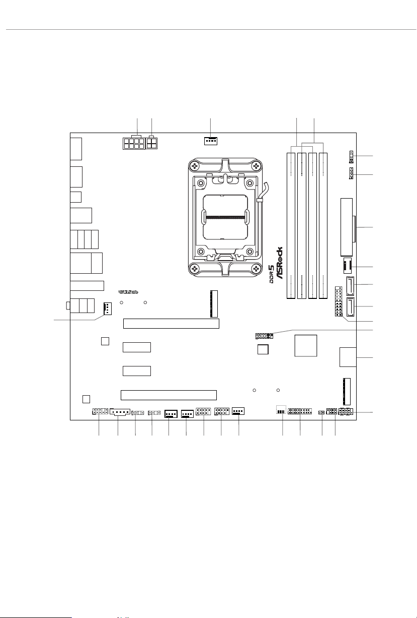
1.3 Motherboard Layout
6
Page 11

No. Description
1 8 pin 12V Power Connector (ATX12V1)
2 4 pin 12V Power Connector (ATX12V2)
3 CPU Fan Connector (CPU_FAN1)
4 2 x 288-pin DDR5 DIMM Slots (DDR5_A1, DDR5_B1)
5 2 x 288-pin DDR5 DIMM Slots (DDR5_A2, DDR5_B2)
6 Addressable LED Header (ADDR_LED3)
7 RGB LED Header (RGB_LED1
8 ATX Power Connector (ATXPWR1)
9 Front Panel Type C USB 3.2 Gen1 Header (USB32_TC2)
10 SATA3 Connector (SATA3_1)
11 SATA3 Connector (SATA3_2)
12 USB 3.2 Gen1 Header (USB32_4 _5)
13 SPI TPM Header (SPI_TPM_J1)
14 SATA3 Connec tors (SATA3_ 4)(Upper), (SATA 3_3)(Lower)
15 System Panel Header (PANEL1)
16 Power LED and Speaker Header (SPK_PLED1)
17 Clear CMOS Jumper (CLRCMOS1)
18 USB 3.2 Gen1 Header (USB32_6_7)
19 Post Status Checker (PSC)
20 Chassis/Water Pump Fan Connector (CHA_FAN3/WP)
21 USB 2.0 Header (USB_5_6)
22 USB 2.0 Header (USB_7_8)
23 Chassis/Water Pump Fan Connector (CHA_FAN2/WP)
24 Chassis/Water Pump Fan Connector (CHA_FAN1/WP)
25 Addressable LED Header (ADDR_LED1)
26 Addressable LED Header (ADDR_LED2)
27 5-pin underbolt AIC Connector (TB1)
28 Front Panel Audio Header (HD_AUDIO1)
29 CPU/Water Pump Fan Connector (CPU_FAN2/WP)
)
B650M PG Riptide WiFi
7
Page 12
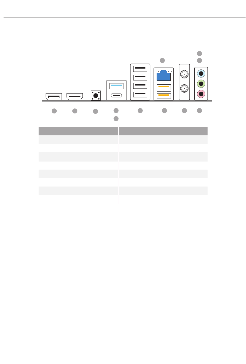
1.4 I/O Panel
2
1
3
12 11
No. Description No. Description
1 2.5G LAN RJ-45 Port* 8 USB 3.2 Gen2 Type-A Port
2 Line In (Light Blue)** (USB32_1)
3 Front Speaker (Lime)** 9 USB 3.2 Gen2 Type-C Port
4 Microphone (Pink)** (USB32_TC1)
5 Antenna Ports 10 BIOS Flashback Button
6 USB 3.2 Gen1 Type-A Ports 11 HDMI Port
(USB32_23)*** 12 DisplayPort 1.4
7 USB 2.0 Ports (USB_1234)
10
8
9
7
46 5
8
Page 13
B650M PG Riptide WiFi
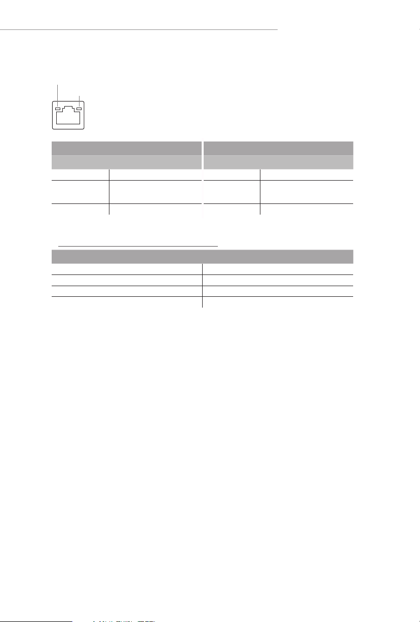
*ere are two LED s on each LAN port. Please re fer to the table below for the LAN port LED indication s.
ACT/LINK LED
SPEED LED
LAN Por t
Activity / Link LED Speed LED
Status Description Status Description
O No Link O 10Mbps connection
Blinking Data Activit y Orange
On Link Green 2.5Gbps connection
** Function of the Audio Ports in 7.1-channel Conguration:
Port Function
Light Blue (Rear panel) Rear Speaker Out
Lime (Rear panel) Front Speaker Out
Pink (Rear panel) Central /Subwoofer Speaker Out
Lime (Front panel) Side Speaker Out
100Mbps/1Gbps
connection
*** USB32_ 23 are the Lightning Gaming Ports.
9
Page 14
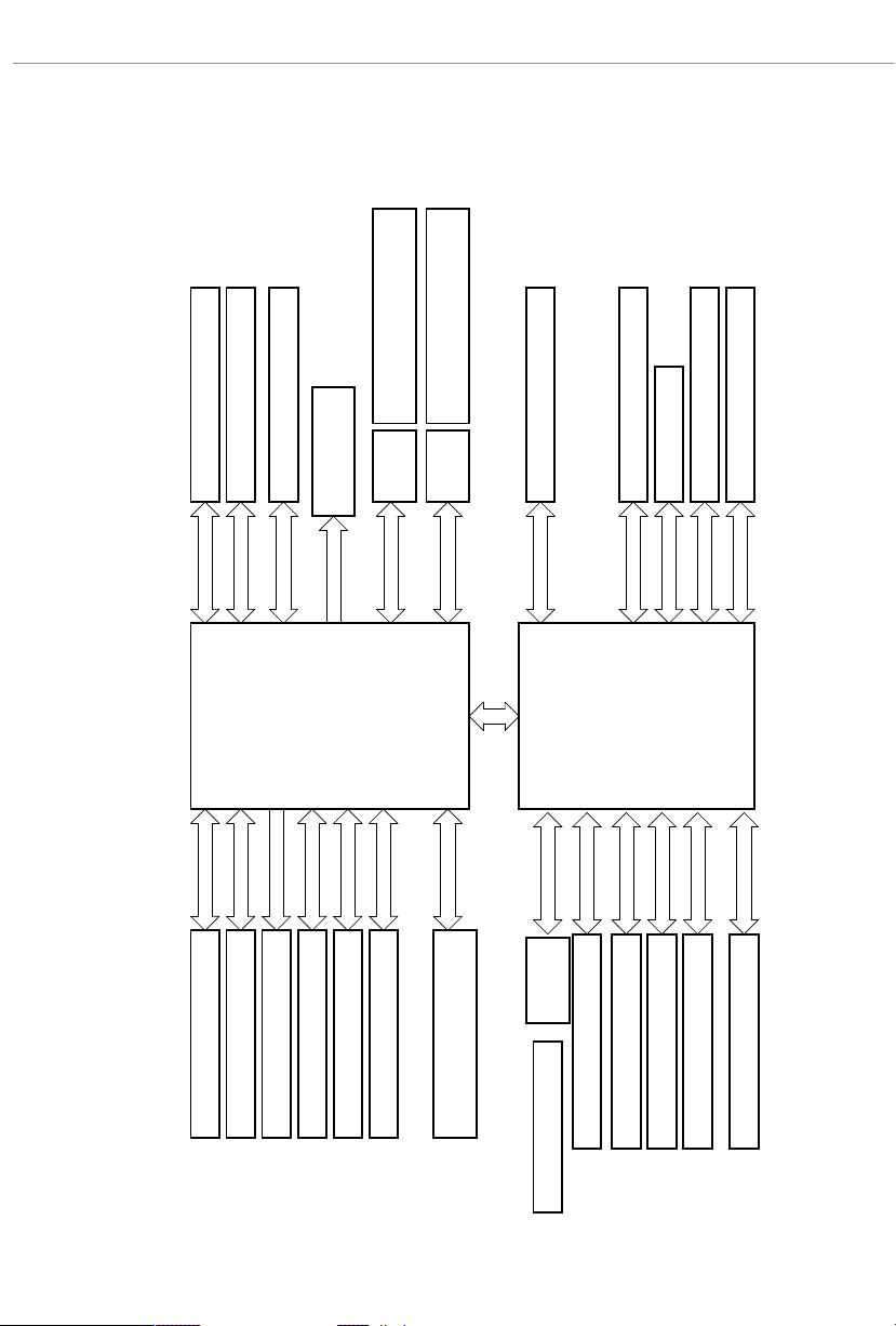
1.5 Block Diagram
Rear USB 3.2 Gen2 Type A
Rear USB 3.2 Gen2 Type C
M.2(PCIe x4)
PCIe x16 Gen4 Slot
x16 Gen4
Channel A
PCIe x4 Slot
x4 Gen5
x4 Gen4
Channel B
DP0
AMD AM5
Processor
LGA1718
AZ(HD Audio)
ReDriver
Displayport
DP1
10Gb/s
SPI
eSPI
ReDriver5Gb/s
10Gb/s
M.2(PCIe x4 Gen4)
x4 Gen4
PCIe x4 Gen4 BUS
480Mb/s
5Gb/s
USB2.0 Hub
GL852
Realtek RTL8125B 2.5G LAN
Key E WiFi
PCIe x1 Slot
PCIe x1 Slot
x1
x1
x1
x1
1st
AMD PROM21
Chipset
5Gb/s
5Gb/s
480Mb/s
SATA 6Gb
10
DDR5 Slot x2
DDR5 Slot x2
HDMI Port
SIO NCT6796D-S
Flash ROM
Audio Codec ALC897 3
Rear USB 3.2 Gen1 1 port
Front USB 3.2 Gen1 4 port
Front USB 3.2 Gen1 Type C
Front USB 2.0 4 port
Rear USB 3.2 Gen1 1 port
SATA 4 port
Rear USB 2.0 4 port
Page 15

B650M PG Riptide WiFi
1.6 802.11ax Wi-Fi 6E Module and ASRock WiFi 2.4/5/6 GHz
Antennas
802.11ax Wi-Fi 6E + BT Module
is motherboard comes with an exclusive 802.11 a/b/g/n/ac/ax Wi-Fi 6E + BT module
that oers support for 802.11 a/b/g/n/ac/ax Wi-Fi 6E connectivity standards and
Bluetooth. Wi-Fi 6E + BT module is an easy-to-use wireless local area network (WLAN)
adapter to support Wi-Fi 6E + BT. Bluetooth standard features Smart Ready technology
that adds a whole new class of functionality into the mobile devices. BT also includes
Low Energy Technology and ensures extraordinary low power consumption for PCs.
* e transmission speed may vary according to the environment.
* Wi-Fi 6E (6GHz band) will be supported by Microso® Windows® 11. e availability
will depend on the dierent regulation status of each country and region. It will be
activated (for supported countries) through Windows Update and soware updates
once available.
* A 6GHz compatible router is required for 6E functionality.
11
Page 16

WiFi Antennas Installation Guide
Step 1
Prepare the WiFi 2.4/5/6 GHz Antennas that
come with the package.
Step 2
Connect the two WiFi 2.4/5/6 GHz Antennas
to the antenna connectors. Turn the antenna
clockwise until it is securely connected.
Step 3
Set the WiFi 2.4/5/6 GHz Antenna as shown in
the illustration.
*You may need to adjust the direction of
the antenna for a stronger signal.
12
Page 17

B650M PG Riptide WiFi
Chapter 2 Installation
is is a Micro ATX form factor motherboard. Before you install the motherboard,
study the conguration of your chassis to ensure that the motherboard ts into it.
Pre-installation Precautions
Take note of the following precautions before you install motherboard components
or change any motherboard settings.
Make sure to unplug the power cord before insta lling or removing the motherboard
•
components. Failure to do so may cause physical injuries and damages to motherboard
components.
In order to avoid damage from static electricity to the motherboard’s components,
•
NEVER place your motherboard directly on a carpet. Also remember to use a grounded
wrist strap or touch a safety grounded object before you handle the components.
Hold components by the edges and do not touch the ICs.
•
Whenever you uninstall any components, place them on a grounded anti-static pad or
•
in the bag that comes with the components.
When placing screws to secure the motherboard to the chassis, please do not over-
•
tighten the screws! Doing so may damage the motherboard.
13
Page 18
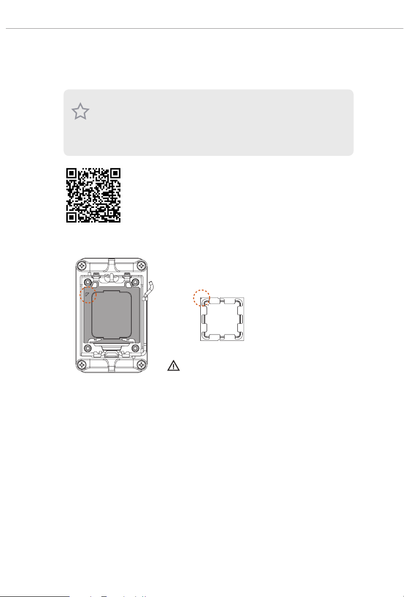
2.1 Installing the CPU
1. Be fore you inser t the 1718-Pin CPU into the socket , please check if the PnP cap is on the
socket, if the CPU surface is unclean , or if there are any bent pins in the socket. Do not
force to in sert the CPU into the socket if above situation is found. Otherwise, the CPU
will be seriously damaged.
2. Unplug all power cables before installing the CPU.
Tutorial Video
14
Turn your CPU to the correct orientation before opening
the CPU socket cover.
Page 19
B650M PG Riptide WiFi
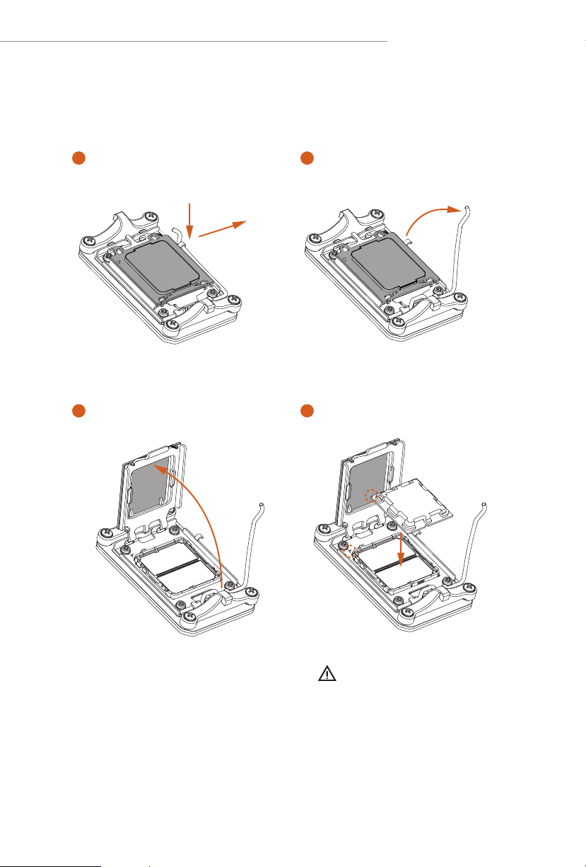
1
A
B
3
2
4
Carefully place the CPU in as at as
possible. Do not drop it.
15
Page 20

5
Make sure the CPU is aligned with the
socket before locking it into place.
6
7
16
Make sure the black cover plate
is always in place until it pops o
when closing the socket lever.
Please save the cover if the processor is removed. e cover must be placed if you wish to
return the motherboard for aer service.
Page 21

B650M PG Riptide WiFi
1
2.2 Installing the CPU Fan and Heatsink
Aer you install the CPU into this motherboard, it is necessary to install a larger
heatsink and cooling fan to dissipate heat. You also need to spray thermal grease
between the CPU and the heatsink to improve heat dissipation. Make sure that the
CPU and the heatsink are securely fastened and in good contact with each other.
Please turn o the power or remove the powe r cord before changing a CPU or heatsink.
Installing the CPU Cooler (Type 1)
2
17
Page 22

3
4
18
CPU_FAN1
Page 23

Installing the CPU Cooler (Type 2)
1
2
B650M PG Riptide WiFi
19
Page 24

3
4
20
CPU_FAN1
Page 25

B650M PG Riptide WiFi
5
CPU_FAN1
RGB_LED1
+12V
*e illustrations shown here are for reference purposes only and may not exactly match
the model you purchase.
21
Page 26

Installing the CPU Cooler (Type 3)
1
2
22
Page 27

B650M PG Riptide WiFi
3
4
23
Page 28

5
AN1
CPU_F
24
Page 29

B650M PG Riptide WiFi
6
CPU_FAN1
RGB_LED1
+12V
or
CPU_FAN1
RGB_LED1
USB_1_2
Please note that only one cable should be used at a time in this step.
If you select RGB_L ED1, please install ASRock utility "ASRock Polychrome SYNC".
If you select USB connector, please install AMD utility "SR3 Settings Soware".
*e illustrations shown here are for reference purposes only and may not exactly match
the model you purchase.
25
Page 30

2.3 Installing Memory Modules (DIMM)
is motherboard provides four 288-pin DDR5 (Double Data Rate 5) DIMM slots,
and supports Dual Channel Memory Technology.
1. For dual channel conguration, you always ne ed to install identical (the same brand,
speed , size and chip-type) DDR5 DIMM pairs.
2. It is un able to activate Dual Ch annel Me mory Technology with only one or three memory
module installed.
3. It is not allowed to ins tall a DDR, DDR2 , DDR3 or DDR4 memor y modul e into a DDR5
slot; otherw ise, this motherboard and DIMM may be damaged .
4. e DIMM only ts in one correct orientation . It will cause pe rmanent damage to the
motherboard and the DIMM if you force the DIMM into the sl ot at incorrec t orientation.
Recommended Memory Conguration
1 DIMM
A1 A2 B1 B2
V
2 DIMMs
A1 A2 B1 B2
V V
4 DIMMs
A1 A2 B1 B2
V V V V
e rst boot may take some time.
Please be patient and refer to the following table for booting time.
*It may vary by dierent setups.
Memory 1st boot after clear CMOS
2 x 16GB 90 sec
2 x 32GB 150 sec
4 x 16GB 170 sec
4 x 32GB 315 se c
26
Page 31

B650M PG Riptide WiFi
1
2
3
27
Page 32

2.4 Connecting the Front Panel Header
1
32:(56:
+''/('
5(6(76:
32:(5/('
32:(5/('
2
RESET SW
HDD LED
28
3$1(/
System Panel Header
910
Power SW (-) RESET SW (+)
B
Power LED (-)
A
Power LED (+)
12
PANEL1
RESET SW (-)Power SW (+)
HDD LED (-)
HDD LED (+)
Front Panel Wires
D
C
ABC D
Page 33

2.5 Installing the Motherboard
W Fi i
RIP TI DE
B650 M PG
B650M PG Riptide WiFi
29
Page 34

2.6 Installing SATA Drives
1
Optical Drive
SATA Drive
2
30
SATA Data Cable
Page 35

B650M PG Riptide WiFi
3
4
SATA Power Connector
SATA Data Connector
31
Page 36

2.7 Installing a Graphics Card
1
32
CLICK!
Page 37

Expansion Slots (PCIe Slots)
ere are 4 PCI Express slots on the motherboard.
Before instal ling an expansion card, ple ase ma ke sure that the power supply is switched o
or the power cord is unplug ged. Please read the documentation of the expansion card and
make necessary hardware settings for the card before you start the installation.
PCIe slots:
PCIE1 (PCIe 4.0 x16 slot) is used for PCIe x16 lane width graphics cards.
PCIE2 (PCIe 3.0 x1 slot) is used for PCIe x1 lane width cards.
PCIE3 (PCIe 3.0 x1 slot) is used for PCIe x1 lane width cards.
PCIE4 (PCIe 4.0 x16 slot) is used for PCIe x4 lane width graphics cards.
PCIe Slot Congurations
PCIE1 PCIE4
Single Graphics Card Gen4x16 N/A
B650M PG Riptide WiFi
Two Graphics Cards in
CrossFireTM Mode
For a better thermal environment, please connect a cha ssis fan to the motherboard’s
chassis fan connector (CHA_ FAN1~3/WP) when using multipl e graphics card s.
Gen4x16 Gen4x4
33
Page 38

2.8 Connecting Peripheral Devices
34
Page 39

2.9 Connecting the Power Connectors
B650M PG Riptide WiFi
$7;9
$7;3:5
35
Page 40

2.10 Power On
1
2
3
4
36
Page 41

B650M PG Riptide WiFi
2.11 Jumpers Setup
e illustration shows how jumpers are setup. When the jumper cap is placed on
the pins, the jumper is “Short”. If no jumper cap is placed on the pins, the jumper is
“O pen”.
Clear CMOS Jumper
(CLRC MOS1) (see p.6, No. 17)
CLRCMOS1 allows you to clear the data in CMOS. e data in CMOS includes
system setup information such as system password, date, time, and system setup
parameters. To clear and reset the system parameters to default setup, please
turn o the computer and unplug the power cord, then use a jumper cap to short
the pins on CLRCMOS1 for 3 seconds. Please remember to remove the jumper
cap aer clearing the CMOS. If you need to clear the CMOS when you just nish
updating the BIOS, you must boot up the system rst, and then shut it down
before you do the clear-CMOS action.
W Fi i
RIP TI DE
B650 M PG
CLRCMOS1
2-pin Jumper
Short: Clear CMOS
Open: Default
37
Page 42

2.12 Onboard Headers and Connectors
Onboard heade rs and connectors are NOT jumpers. Do NOT place jumper caps over these
System Panel Header
(9-pin PANEL1) (see p.6, No. 15)
Connect the power button, reset button and system status indicator on the chassis
to this header according to the pin assignments below. Note the positive and
negative pins before connecting the cables.
heade rs and connectors. Pla cing jumper caps over the head ers and connectors will cau se
permanent damage to the motherboard.
W Fi i
RIP TI DE
B650 M PG
PANEL1
PLED+
1
HDLED+
PLED-
PWRBTN#
GND
HDLED-
GND
GND
RESET#
PWRBTN (Power Bu tton):
Connec t to the power button on the chassis front panel . You may congure the way to tur n
o your system using the power button.
RESET (Reset Button):
Connec t to the reset button on the chassis front panel . Press the reset button to restart the
computer if the computer freezes and fails to perform a nor mal restart .
PLED (Syste m Power LED):
Connec t to the power status indicator on the cha ssis front panel. e LED is on when the
system is operating. e LED keeps blinking when th e syste m is in S1/S3 sleep state. e
LED is o when the system is in S4 sleep state or powe red o (S5).
HDLED (Ha rd Drive Activity LED):
Connec t to the hard drive ac tivit y LED on the chassis front pane l. e LED is on when the
hard drive is reading or writing data.
e front panel de sign may dier by chassis. A f ront panel module mainly consi sts of power
button, reset button, power LED, hard drive a ctivity LED, speaker and etc. When connecting your ch assis front panel module to this header, make sure the wire assignments and the
pin assignme nts are matched correctly.
38
Page 43

B650M PG Riptide WiFi
1
+5V
DUMMY
PLED+
PLED+
PLED-
DUMMY
SPEAKER
Power LED and Speaker Header
(7-pin SPK_PLED1) (see p.6, No. 16)
Please connect the chassis power LED and the chassis speaker to this header.
W Fi i
RIP TI DE
B650 M PG
Serial ATA3 Connectors
Ver ti c a l:
(SATA3_1) (see p.6, No. 10)
(SATA3_2) (see p.6, No. 11)
Right Angle:
(SATA3_3) (see p.6, No. 14)(Lower)
(SATA3_4) (see p.6, No. 14)(Upper)
ese four SATA3 connectors support SATA data cables for internal storage
devices with up to 6.0 Gb/s data transfer rate.
SPK_PLED1
W Fi i
RIP TI DE
B650 M PG
SATA3_2 SATA3_1
SATA3_4
SATA3_3
39
Page 44

USB 2.0 Headers
DUMMY
GND
GND
P+
P-
USB_PWR
P+
P-
USB_PWR
1
DUMMY
GND
GND
P+
P-
USB_PWR
P+
P-
USB_PWR
1
(9-pin USB_5_6) (see p.6, No. 21)
(9-pin USB_7_8) (see p.6, No. 22)
ere are two headers on this motherboard. Each USB 2.0 header can support two
ports.
W Fi i
RIP TI DE
B650 M PG
USB_5_6
USB_7_ 8
40
Page 45

B650M PG Riptide WiFi
IntA_P_D+
USB 3.2 Gen1 Headers
(19-pin USB32_4_5) (see p.6, No. 12)
(19-pin USB32_6_7) (see p.6, No. 18)
ere are two headers on this motherboard. Each USB 3.2 Gen1 header can
support two ports.
W Fi i
RIP TI DE
B650 M PG
USB32_4 _5
Vbus
IntA_PA_SSRX-
IntA_PA_SSRX+
GND
IntA_PA_SSTX-
IntA_PA_SSTX+
GND
IntA_PA_D-
IntA_PA_D+
VbusVbus
IntA_PB_SSRX-
IntA_PB_SSRX+
GND
IntA_PB_SSTX-
IntA_PB_SSTX+
GND
IntA_PB_D-
IntA_PB_D+
Dummy
1
USB32_6_7
IntA_P_D-
GND
1
IntA_P_D-
IntA_P_D+
ID
IntA_P_SSTX+
IntA_P_SSTX-
GND
IntA_P_SSTX-
IntA_P_SSTX+
GND
IntA_P_SSRX+
IntA_P_SSRX-
Vbus
IntA_P_SSRX-
IntA_P_SSRX+
GND
Vbus
41
Page 46

Front Panel Type C USB 3.2 Gen1 Header
J_SENSE
OUT2_L
1
MIC_RET
PRESENCE#
GND
OUT2_R
MIC2_R
MIC2_L
OUT_RET
(20-pin USB32_TC2) (see p.6, No. 9)
ere is one Front Panel Type C USB 3.2 Gen1 Header on this motherboard. is
header is used for connecting a USB 3.2 Gen1 module for additional USB 3.2 Gen1
ports.
W Fi i
RIP TI DE
B650 M PG
USB32_TC2
USB Type-C Cable
Front Panel Audio Header
(9-pin HD_AUDIO1) (see p.6, No. 28)
is header is for connecting audio devices to the front audio panel.
42
W Fi i
RIP TI DE
B650 M PG
HD_AUDIO1
High Denition Audio supports Jack Sensing , but the panel wire on the chassis must support HDA to function cor rectly. Please follow the instructions in our manual and chassi s
manual to install your system .
Page 47

Chassis/Water Pump Fan Connectors
GND
L
GND
L
GND
L
(4-pin CHA_FAN1/WP) (see p.6, No. 24)
(4-pin CHA_FAN2/WP) (see p.6, No. 23)
(4-pin CHA_FAN3/WP) (see p.6, No. 20)
is motherboard provides three 4-Pin water cooling
you plan to connect a 3-Pin
chassis
water cooler fan, please connect it to Pin 1-3.
W Fi i
RIP TI DE
B650 M PG
chassis
fan connectors. If
CH A _FAN3/ WP
FAN_VOLTAGE
CHA_FAN_SPEED
FAN_SPEED_CONTRO
1 2 3 4
B650M PG Riptide WiFi
CH A _FAN1/ WP
FAN_VOLTAGE
CHA_FAN_SPEED
FAN_SPEED_CONTRO
1 2 3 4
CH A _FAN2/WP
FAN_VOLTAGE
CHA_FAN_SPEED
FAN_SPEED_CONTRO
1 2 3 4
43
Page 48

CPU Fan Connector
FAN_SPEED_CONTROL
4 3 2 1
1
2
3
4
L
(4-pin CPU_FAN1) (see p.6, No. 3)
is motherboard provides a 4-Pin CPU fan (Quiet Fan) connector. If you plan to
connect a 3-Pin CPU fan, please connect it to Pin 1-3.
W Fi i
RIP TI DE
B650 M PG
CPU_ FA N1
GND
+12V
CPU_F
AN_SPEED
CPU/Water Pump Fan Connector
(4-pin CPU_FAN2/WP) (see p.6, No. 29)
is motherboard provides a 4-Pin water cooling CPU fan connector. If you plan
to connect a 3-Pin CPU water cooler fan, please connect it to Pin 1-3.
W Fi i
RIP TI DE
B650 M PG
CPU_ FA N2/ W P
GND
FAN_VOLTAGE
CPU_FAN_SPEED
FAN_SPEED_CONTRO
44
Page 49

B650M PG Riptide WiFi
4
1
8 5
ATX Power Connector
(24-pin ATXPWR1) (see p.6, No. 8)
is motherboard provides a 24-pin ATX power connector. To use a 20-pin ATX
power supply, please plug it along Pin 1 and Pin 13.
W Fi i
RIP TI DE
B650 M PG
ATX PW R1
12
24
1
13
ATX 12V Power Connector
(8-pin ATX12V1) (see p.6, No. 1)
is motherboard provides a 8-pin ATX 12V power connector. To use a 4-pin
ATX power supply, please plug it along Pin 1 and Pin 5.
*Warning: Please make sure that the power cable connected is for the CPU and
not the graphics card. Do not plug the PCIe power cable to this
connector.
W Fi i
RIP TI DE
B650 M PG
ATX12V1
45
Page 50

ATX 12V Power Connector
1
SPI_DQ3
#
(4-pin ATX12V2) (see p.6, No. 2)
Please connect an ATX 12V power supply to this connector.
*e power supply plug ts into this connector in only one orientation.
*Connecting an ATX 12V 4-pin cable to ATX12V2 is optional.
*For advanced overclocking we suggest using this connector together with
ATX12V1.
W Fi i
RIP TI DE
B650 M PG
ATX12V2
SPI TPM Header
(13-pin SPI_TPM_J1) (see p.6, No. 13)
is connector supports SPI Trusted Platform Module (TPM) system, which can securely
store keys, digital certicates, passwords, and data. A TPM system also helps enhance
network security, protects digital identities, and ensures platform integrity.
W Fi i
RIP TI DE
B650 M PG
SPI_TPM_ J1
SPI_PWR
Dummy
CLK
SPI_MOSI
RST#
TPM_PIRQ
46
SPI_TPM_CS
GND
RSMRST#
SPI_MISO
SPI_CS0
SPI_DQ2
Page 51

B650M PG Riptide WiFi
1
underbolt AIC Connector
(5-pin TB1) (see p.6, No. 27)
Please connect a underboltTM add-in card (AIC) to the underbolt AIC connector via
the GPIO cable.
*Please install the underboltTM AIC card to PCIE4 (default slot).
*For the underbolt compatibility and limitation, please visit w ww.asrock.com.
W Fi i
RIP TI DE
B650 M PG
TB1
47
Page 52

RGB LED Header
B
+12V
(4-pin RGB_LED1) (see p.6, No. 7)
is RGB header is used to connect RGB LED extension cable which allow users to choose
from various LED lighting eects.
Caution: Never install the RGB LED cable in the wrong orientation; otherwise, the
cable may be damaged.
W Fi i
RIP TI DE
B650 M PG
RGB_LED1
R
G
1
48
Connect your RGB LED strip to the
Header (RGB_LED1)
1. Never install the RGB LED cable in the w rong orientation; otherwise, the cable
may be damaged.
2. Before installing or removing your RGB LED cable, pl ease power o your system
and unplug the power cord from the power supply. Failure to do so may cause damages to motherboard components.
1. Please note that the RGB LED strips do not come with the package.
2. e RGB LED header supports standard 5050 RGB LED strip (12V/G/R/B), with a
maximum power rating of 3A (12V) and length within 2 meters.
on the motherboard.
RGB LED
1
B
R
G
V
2
1
Page 53

B650M PG Riptide WiFi
1
1
Addressable LED Headers
(3-pi n A DDR_LE D1) (see p.6, No. 25)
(3-pin ADDR_LED2) (see p.6, No. 26)
(3-pin ADDR_LED3) (see p.6, No. 6)
ese headers are used to connect
choose from various LED lighting eects.
Caution: Never install the Addressable LED cable in the wrong orientation; otherwise,
the cable may be damaged.
W Fi i
RIP TI DE
B650 M PG
Addressable
LED extension cables which allow users to
ADDR_LED3
ADDR_LED1
GND
DO_ADDR
VOUT
ADDR_LED2
GND
DO_ADDR
VOUT
Connect your
to the
LED1 / ADDR_LED2 / ADDR_LED3)
Addressable RGB LED
strips
Addressable LED Headers (ADDR_
on
the motherboard.
1
49
Page 54

1. Never install the RGB LED cable in the w rong orientation; otherwise, the cable may be
damaged.
2. Before installing or removing your RGB LED cable, pl ease power o your system and
unplug the power cord from the power supply. Failure to do so may cau se damages to
motherboard components.
1. Please note that the RGB LED strips do not come with the package.
2. e RGB LED header supports WS2812B addressable RGB LED strip (5V/Data/
GND), with a ma ximum power rating of 3A (5V) and length within 2 meters .
50
Page 55

B650M PG Riptide WiFi
2.13 Smart Button
e motherboard has a smart button: BIOS Flashback Button, allowing users to
ash the BIOS.
BIOS Flashback Button
(BIOS_FB1) (see p.8, No. 9)
BIOS Flashback Button allows users to ash the BIOS.
W Fi i
RIP TI DE
B650 M PG
USB BIOS Flashback port
BIOS_FB1
51
Page 56

ASRock BIOS Flashback feature al lows you to update BIOS wit hout powering on the system, even
without CPU.
Before u sing the BIOS Flashback function, please suspend BitLocke r and any encry ption
or security relying on the TPM. Make sure that you have already stored and backup-ed
the recovery key. If the recovery key is missing while e ncryption is active, the d ata will stay
encrypted and the system will not boot into the operating system. It is recommended to disable f TPM before updating the BIOS. Otherwise an unpre dictable failure may occur.
To use the USB BIOS Flashback func tion, Please fol low the steps below.
1. Download the latest BIOS le from ASRock 's website : http://www.asrock.com.
2. Copy t he BIOS le to your USB a sh drive. Please make sure the le system of
your USB ash drive must be FAT32.
3. Extract BIOS le from the zip le.
4. Rename the le to “creative.rom” and save it to t he root directory of X: USB ash drive.
5. Plug the 24 pin power con nector to the mot herboard. en turn on the power supply's AC
switch.
*ere is no need to power on t he system.
6. en plug your USB drive to the USB BIOS Flashback por t.
7. Press the BIOS Flashback Switch for about three seconds. en the LED starts to blink.
8. Wait unti l the LED stops blinking, indicating that BIOS ashing has been completed.
*If the LED light turns solid green, this means that the BIOS Flashback is not
operating properly. Please ma ke sure that you plug t he USB drive to the USB BIOS Flashback
port.
**If the LED does not light up at a ll then please disconnect power from the system and remove/
disconnect t he CMOS battery from the motherboard for several minutes. Reconnect power
and battery and try agai n.
52
Page 57

B650M PG Riptide WiFi
DRAM
VGA
CPU
BOOT
2.14 Post Status Checker
Post Status Checker (PSC) diagnoses the computer when users power on the
machine. It emits a red light to indicate whether the CPU, memory, VGA or
storage is dysfunctional. e lights go o if the four mentioned above are function-
ing normally.
W Fi i
RIP TI DE
B650 M PG
Tutorial Video
53
Page 58

2.15 M.2 SSD Module Installation Guide (M2_1)
2
e M.2 is a small size and versatile card edge connector that aims to replace mPCIe and
mSATA. e Blazing M.2 Socket (M2 _1, Key M) supports type 2260/2280 PCIe Gen5x4 (128
Gb/s) mode.
Installing the M.2 SSD Module
Step 1
Prepare a M.2 SSD module.
1
AB
No. 1 2
Nut Location A B
PCB Length 6cm 8cm
Module Type Type 2 260 Ty p e 2 2 8 0
Step 2
Depending on the PCB type and
length of your M.2 SSD module, nd
the corresponding nut location to be
used.
54
Page 59

Step 3
B650M PG Riptide WiFi
2
Before installing a M.2 SSD
1
module, please loosen the screws to
remove the M.2 heatsink.
1
*Please remove the protective lms
on the bottom side of the M.2
heatsink before you install a M.2
SSD module.
Step 4
Peel o the yellow protective lm on
the nut A. Prepare the M.2 stando
that comes with the package, and
B
A
hand tighten it into the nut A. Skip
Step 4 if your M.2 SSD module is
Type 228 0 .
Step 5
Align and gently insert the M.2 SSD
module into the M.2 slot. Please
be aware that the M.2 SSD module
only ts in one orientation.
AB
AB
o
20
55
Page 60

NUT1NUT2B
Correct Installation:
e SSD's PCB is in proper place, and
the M.2 heatsink can be screwed in.
Step 6
Tighten the screw with a screwdriver
to secure the module into place.
Please do not overtighten the screw
as this might damage the module.
Skip Step 6 if your M.2 SSD module is
Type 228 0 .
Step 7
Before securing the M.2 heatsink,
make sure to align the notch on
the SSD to the stando on the
motherboard if you use a Type 2280
SSD module; otherwise, the SSD
module may be damaged.
56
Incorrect Installation:
e SSD's PCB sits between M.2 heatsink
and stando. Do not continue.
Page 61

Step 8
B650M PG Riptide WiFi
1
2
For the latest updates of M.2 SSD module support list, please visit our website for details:
http://www.asrock.com
Tighten the screws with a screwdriver
3
to secure the module (if your M.2
SSD module is Type 2280) and M.2
heatsink into place in the order
shown. Tighten screw opposite the
M.2 connector rst (2), and then
tighten the one next to the M.2
connector (3).
*Please do not overtighten the screw
as this might damage the module and
M.2 heatsink.
57
Page 62

2.16 M.2 SSD Module Installation Guide (M2_2)
2
e M.2 is a small size and versatile card edge connector that aims to replace mPCIe and
mSATA. e Hyper M.2 Socket (M2_ 2, Key M), supports type 2260/2280 PCIe Gen4x4 (64
Gb/s) mode.
Installing the M.2 SSD Module
Step 1
Prepare a M.2 SSD module and the
screw.
1
AB
No. 1 2
Nut Location A B
PCB Length 6cm 8cm
Module Type Type 2 260 Ty p e 2 2 8 0
Step 2
Depending on the PCB type and
length of your M.2 SSD module, nd
the corresponding nut location to be
used.
58
Page 63

B650M PG Riptide WiFi
Step 3
Move the stando based on the
module type and length.
B
B
A
A
AB
e stando is placed at the nut
location B by default. Skip Step 3 and
4 and go straight to Step 5 if you are
going to use the default nut.
Otherwise, release the stando by
hand.
Step 4
Peel o the yellow protective lm on
the nut to be used. Hand tighten the
stando into the desired nut location
on the motherboard.
Step 5
Align and gently insert the M.2 SSD
module into the M.2 slot. Please
be aware that the M.2 SSD module
only ts in one orientation.
AB
o
20
Step 6
Tighten the screw with a screwdriver
to secure the module into place.
NUT1NUT2B
Please do not overtighten the screw
as this might damage the module.
For the latest updates of M.2 SSD module support list, please visit our website for details:
http://www.asrock.com
59
Page 64

e terms HDMI® and HDMI High-Denition Multimedia Interface, and the HDMI
logo are trademarks or registered trademarks of HDMI Licensing LLC in the United
States and other countries.
WARNING
THIS PRODUCT CONTAINS A BUTTOON BATTERY
If swallowed, a button battery can cause serious injury or death.
Please keep batteries out of sight or reach of children.
CALIFORNIA, USA ONLY
e Lithium battery adopted on this motherboard contains Perchlorate, a toxic substance
controlled in Perchlorate Best Management Practices (BMP) regulations passed by the
California Legislature. When you discard the Lithium battery in California, USA, please
follow the related regulations in advance.
“Perchlorate Material-special handling may apply, see www.dtsc.ca.gov/hazardouswaste/
perchlorate”
AUSTRALIA ONLY
Our goods come with guarantees that cannot be excluded under the Australian Consumer
Law. You are entitled to a replacement or refund for a major failure and compensation for
any other reasonably foreseeable loss or damage caused by our goods. You are also entitled
to have the goods repaired or replaced if the goods fail to be of acceptable quality and the
failure does not amount to a major failure. If you require assistance please call ASRock Tel
: +886-2-28965588 ext.123 (Standard International call charges apply)
Page 65

ASRock INC. hereby declares that this device is in compliance with the essential requirements and other relevant provisions of related UKCA Directives. Full text of UKCA declaration of conformity is available at: http://www.asrock.com
ASRock INC. hereby declares that this device is in compliance with the essential requirements and other relevant provisions of related Directives. Full text of EU declaration of
conformity is available at: http://www.asrock.com
ASRock follows the green design concept to design and manufacture our products, and
makes sure that each stage of the product life cycle of ASRock product is in line with global
environmental regulations. In addition, ASRock disclose the relevant information based
on regulation requirements.
Please refer to https://www.asrock.com/general/about.asp?cat=Responsibility for information disclosure based on regulation requirements ASRock is complied with.
DO NOT throw the motherboard in municipal waste. is product has been
designed to enable proper reuse of parts and recycling. is symbol of the
crossed out wheeled bin indicates that the product (electrical and electronic
equipment) should not be placed in municipal waste. Check local regulations
for disposal of electronic products.
CE Warning
is device complies with directive 2014/53/EU issued by the Commision of the
European Community.
is equipment complies with EU radiation exposure limits set forth for an
uncontrolled environment.
is equipment should be installed and operated with minimum distance 20cm
between the radiator & your body.
Page 66

Operations in the 5.15-5.35GHz band are restricted to indoor usage only.
Radio transmit power per transceiver type
Function Frequency Maximum Output Power (EIRP)
2400-2483.5 MHz 18.5 + / -1.5 dbm
5150-5250 MHz 21.5 + / -1.5 dbm
WiFi
Bluetooth 2400-2483.5 MHz 8.5 + / -1.5 dbm
5250-5350 MHz
5470-5725 MHz
18.5 + / -1.5 dbm (no TPC)
21.5 + / -1.5 dbm (TPC)
25.5 + / -1.5 dbm (no TPC)
28.5 + / -1.5 dbm (TPC)
 Loading...