

Page 1
Page 2

Version 1.1
Published December 2020
Copyright©2020 ASRock INC. All rights reserved.
Copyright Notice:
No part of this documentation may be reproduced, transcribed, transmitted, or
translated in any language, in any form or by any means, except duplication of
documentation by the purchaser for backup purpose, without written consent of
ASRock Inc.
Products and corporate names appearing in this documentation may or may not
be registered trademarks or copyrights of their respective companies, and are used
only for identication or explanation and to the owners’ benet, without intent to
infringe.
Disclaimer:
Specications and information contained in this documentation are furnished for
informational use only and subject to change without notice, and should not be
constructed as a commitment by ASRock. ASRock assumes no responsibility for
any errors or omissions that may appear in this documentation.
With respect to the contents of this documentation, ASRock does not provide
warranty of any kind, either expressed or implied, including but not limited to
the implied warranties or conditions of merchantability or tness for a particular
purpose.
In no event shall ASRock, its directors, ocers, employees, or agents be liable for
any indirect, special, incidental, or consequential damages (including damages for
loss of prots, loss of business, loss of data, interruption of business and the like),
even if ASRock has been advised of the possibility of such damages arising from any
defect or error in the documentation or product.
is device complies with Part 15 of the FCC Rules. Operation is subject to the following
two conditions:
(1) this device may not cause harmful interference, and
(2) this device must accept any interference received, including interference that
may cause undesired operation.
CALIFORNIA, USA ONLY
e Lithium batter y adopted on this motherboard contains Perchlorate, a toxic substance
controlled in Perchlorate Best Management Practices (BMP) regulations passed by the
California Legislature. When you discard the Lithium battery in California, USA, please
follow the related regulations in advance.
“Perchlorate Material-special handling may apply, see www.dtsc.ca.gov/hazardouswaste/
perchlorate”
ASRock Website: http://www.asrock.com
Page 3

AUSTRALIA ONLY
Our goods come with guarantees that cannot be excluded under the Australian
Consumer Law. You are entitled to a replacement or refund for a major failure and
compensation for any other reasonably foreseeable loss or damage caused by our
goods. You are also entitled to have the goods repaired or replaced if the goods fail
to be of acceptable quality and the failure does not amount to a major failure. If
you require assistance please call ASRock Tel : +886-2-28965588 ext.123 (Standard
International call charges apply)
e terms HDMI® and HDMI High-Denition Multimedia Interface, and the
HDMI logo are trademarks or registered trademarks of HDMI Licensing LLC in the
United States and other countries.
Page 4
CE Warning
is device complies with directive 2014/53/EU issued by the Commision of the European
Community.
is equipment complies with EU radiation exposure limits set forth for an uncontrolled
environment.
is equipment should be installed and operated with minimum distance 20cm between
the radiator & your body.
Operations in the 5.15-5.35GHz band are restricted to indoor usage only.
Radio transmit power per transceiver type
Function Frequency Maximum Output Power (EIRP)
2400-2483.5 MHz 18.5 + / -1.5 dbm
5150-5250 MHz 21.5 + / -1.5 dbm
WiFi
Bluetooth 2400-2483.5 MHz 8.5 + / -1.5 dbm
5250-5350 MHz
5470-5725 MHz
18.5 + / -1.5 dbm (no TPC)
21.5 + / -1.5 dbm (TPC)
25.5 + / -1.5 dbm (no TPC)
28.5 + / -1.5 dbm (TPC)
Page 5

Contents
Chapter 1 Introduction 1
1.1 Package Contents 1
1.2 Specications 2
1.3 Motherboard Layout 8
1.4 I/O Panel 10
1.5 WiFi-802.11ax Module and ASRock WiFi 2.4/5 GHz
Antenna 12
Chapter 2 Installation 13
2.1 Installing the CPU 14
2.2 Installing the CPU Fan and Heatsink 16
2.3 Installing Memory Modules (DIMM) 24
2.4 Expansion Slots (PCI Express Slots) 27
2.5 Jumpers Setup 29
2.6 Onboard Headers and Connectors 30
2.7 Smart Switches 36
2.8 Dr. Debug 38
2.9 CrossFireXTM , 3-Way CrossFireXTM and Quad CrossFireXTM
Operation Guide 44
2.9.1 Installing Two CrossFireXTM-Ready Graphics Cards 44
2.9.2 Installing Three CrossFireXTM-Ready Graphics Cards 46
2.10 M.2_SSD (NGFF) Module Installation Guide (M2_1) 48
2.11 M.2_SSD (NGFF) Module Installation Guide (M2_2) 51
Page 6

Chapter 3 Software and Utilities Operation 54
3.1 Installing Drivers 54
3.2 ASRock Motherboard Utility (A-Tuning) 55
3.2.1 Installing ASRock Motherboard Utility (A-Tuning) 55
3.2.2 Using ASRock Motherboard Utility (A-Tuning) 55
3.3 ASRock Live Update & APP Shop 58
3.3.1 UI Overview 58
3.3.2 Apps 59
3.3.3 BIOS & Drivers 62
3.3.4 Setting 63
3.4 Nahimic Audio 64
3.5 Razer Synapse 3 65
Chapter 4 UEFI SETUP UTILITY 68
4.1 Introduction 68
4.1.1 UEFI Menu Bar 68
4.1.2 Navigation Keys 69
4.2 Main Screen 70
4.3 OC Tweaker Screen 71
4.4 Advanced Screen 75
4.4.1 CPU Conguration 76
4.4.2 Onboard Devices Conguration 77
4.4.3 Storage Conguration 79
4.4.4 ACPI Conguration 80
4.4.5 Trusted Computing 81
Page 7

4.4.6 AMD PBS 82
4.4.7 AMD Overclocking 83
4.4.8 AMD CBS 84
4.5 Tools 85
4.6 Hardware Health Event Monitoring Screen 86
4.7 Security Screen 89
4.8 Boot Screen 90
4.9 Exit Screen 92
Page 8

B550 Taichi Razer Edition
Chapter 1 Introduction
ank you for purchasing ASRock B550 Taichi Razer Edition motherboard, a
reliable motherboard produced under ASRock’s consistently stringent quality
control. It delivers excellent performance with robust design conforming to
ASRock’s commitment to quality and endurance.
In this documentation, Chapter 1 and 2 contains the introduction of the
motherboard and step-by-step installation guides. Chapter 3 contains the operation
guide of the soware and utilities. Chapter 4 contains the conguration guide of
the BIOS setup.
Becau se the motherboard specication s and the BIOS soware might be upd ated, the
content of this documentation will be subject to change without notice. In case any modications of this d ocumentation occur, the updated version will be availa ble on ASRock’s
website w ithout further notice . If you require technical support rel ated to this mothe rboard, please v isit our website for specic information about the model you are using. You
may nd the l atest VGA cards and CPU suppor t list on ASRock’s website as well. ASRock
website http://www.asrock.com.
1.1 Package Contents
ASRock B550 Taichi Razer Edition Motherboard (ATX Form Factor)
•
ASRock B550 Taichi Razer Edition Quick Installation Guide
•
ASRock B550 Taichi Razer Edition Support CD
•
4 x Serial ATA (SATA) Data Cables (Optional)
•
1 x ASRock WiFi 2.4/5 GHz Antenna (Optional)
•
1 x ASRock Screwdriver (Optional)
•
2 x Screws for M.2 Sockets (Optiona l)
•
2 x Standos for M.2 Sockets (Optional)
•
English
1
Page 9

English
1.2 Specications
Platform
CPU
Chipset
Memory
•
•
•
* Not compatible with AMD Ryzen™ 5 3400G and Ryzen™ 3
3200G.
•
•
•
•
•
•
•
•
* Please refer to Memory Support List on ASRock’s website for
more information. (http://www.asrock.com/)
* Please refer to page 24 for DDR4 UDIMM maximum
frequency support.
•
•
•
ATX Form Factor
2oz Copper PCB
Supports 3rd Gen AMD AM4 Ryzen™ / future AMD Ryzen™
Processors (3000, 4000 and 5000 Series Processors)*
Digi Power design
16 Power Phase design
AMD B550
Dual Channel DDR4 Memory Technology
4 x DDR4 DIMM Slots
AMD Ryzen series CPUs (Vermeer) support DDR4 4733+
(OC)/4600(OC)/4533(OC)/4466(OC)/4400(OC)/4333(OC)/
4266(OC)/4200(OC)/4133(OC)/4000(OC)/3866(OC)/380 0
(OC)/3733(OC)/360 0(OC)/3466(OC)/3200/2933/2667/
2400/2133 ECC & non-ECC, un-buered memory*
AMD Ryzen series CPUs (Matisse) support DDR4 4733+
(OC)/4600(OC)/4533(OC)/4466(OC)/4400(OC)/4333(OC)/
4266(OC)/4200(OC)/4133(OC)/4000(OC)/3866(OC)/380 0
(OC)/3733(OC)/360 0(OC)/3466(OC)/3200/2933/2667/
2400/2133 ECC & non-ECC, un-buered memory*
AMD Ryzen series APUs (Renoir) support DDR4 4733+
(OC)/4666(OC)/4600(OC)/4533(OC)/4466(OC)/4400(OC)/
4333(OC)/4266(OC)/420 0(OC)/4133(OC)/4000(OC)/3866
(OC)/3800(OC)/3733(OC)/3600(OC)/3466(OC)/3200/2933/
2667/2400/2133 ECC & non-ECC, un-buered memory*
Max. capacity of system memor y: 128GB
Supports Extreme Memory Prole (XMP) memory modules
15μ Gold Contact in DIMM Slots
2
Page 10

B550 Taichi Razer Edition
Expansion
Slot
AMD Ryzen series CPUs (Vermeer)
3 x PCI Express x16 Slots (PCIE1/PCIE3/PCIE5: single at
•
Gen4x16 (PCIE1); dual at Gen4x8 (PCIE1) / Gen4x8 (PCIE3);
triple at Gen4x8 (PCIE1) / Gen4x8 (PCIE3) / Gen3x4
(PCI E5))*
AMD Ryzen series CPUs (Matisse)
3 x PCI Express x16 Slots (PCIE1/PCIE3/PCIE5: single at
•
Gen4x16 (PCIE1); dual at Gen4x8 (PCIE1) / Gen4x8 (PCIE3);
triple at Gen4x8 (PCIE1) / Gen4x8 (PCIE3) / Gen3x4
(PCI E5))*
AMD Ryzen series APUs (Renoir)
3 x PCI Express x16 Slots (PCIE1/PCIE3/PCIE5: single at
•
Gen3x16 (PCIE1); dual at Gen3x8 (PCIE1) / Gen3x8 (PCIE3);
triple at Gen3x8 (PCIE1) / Gen3x8 (PCIE3) / Gen3x4
(PCI E5))*
* If PCIE2 or PCIE4 is occupied, PCIE5 will downgrade to x2
mode.
* Supports NVMe SSD as boot disks
2 x PCI Express 3.0 x1 Slots
•
Supports AMD Quad CrossFireXTM, 3-Way CrossFireXTM
•
and CrossFireX
1 x Vertical M.2 Socket (Key E) with the bundled WiFi-
•
802.11ax module (on the rear I/O)
15μ Gold Contact in VGA PCIe Slot (PCIE1)
•
TM
Graphics
Integrated AMD RadeonTM Vega Series Graphics in Ryzen
•
Series APU*
* Actual support may vary by CPU
DirectX 12, Pixel Shader 5.0
•
Shared memory default 2GB. Max Shared memory supports
•
up to 16GB.
* e Max shared memory 16GB requires 32GB system memory
installed.
Dual graphics output: support HDMI and DisplayPort 1.4
•
ports by independent display controllers
Supports HDMI 2.1 with max. resolution up to 4K x 2K
•
(4096x2160) @ 60Hz
Supports DisplayPort 1.4 Input with max. resolution up to
•
5K (5120x2880)@120Hz
English
3
Page 11

Audio
Supports Auto Lip Sync, Deep Color (12bpc), xvYCC and
•
HBR (High Bit Rate Audio) with HDMI 2.1 Port (Compliant
HDMI monitor is required)
Supports HDR (High Dynamic Range) with HDMI 2.1
•
Supports HDCP 2.3 with HDMI 2.1 and DisplayPort 1.4
•
Ports
Supports 4K Ultra HD (UHD) playback with HDMI 2.1 and
•
DisplayPort 1.4 Ports
Supports Microso PlayReady®
•
7.1 CH HD Audio with Content Protection (Realtek
•
ALC1220 Audio Codec)
Premium Blu-ray Audio support
•
Supports Surge Protection
•
NE5532 Premium Headset Amplier for Front Panel Audio
•
Connector (Supports up to 600 Ohm headsets)
Pure Power-In
•
Direct Drive Technology
•
PCB Isolate Shielding
•
Impedance Sensing on Rear Out port
•
Individual PCB Layers for R/L Audio Channel
•
Gold Audio Jacks
•
15μ Gold Audio Connector
•
Nahimic Audio
•
English
4
LAN
Wireless
LAN
2.5 Gigabit LAN 10/100/1000/2500 Mb/s
•
1 x Killer® E3100X (PCIE x1 Gigabit LAN 10/100/1000/2500
•
Mb/s)
Supports Killer LAN Soware
•
Supports Killer DoubleShotTM Pro
•
Supports Wake-On-LAN
•
Supports Lightning/ESD Protection
•
Supports Energy Ecient Ethernet 802.3az
•
Supports PXE
•
Killer AX1650x 802.11ax WiFi Module
•
Supports IEEE 802.11a/b/g/n/ax
•
Supports Dual-Band (2.4/5 GHz)
•
Supports Killer WiFi6 802.11ax (2.4Gbps)
•
2 antennas to support 2 (Transmit) x 2 (Receive) diversity
•
technolog y
Page 12

Rear Panel
I/O
B550 Taichi Razer Edition
Supports Bluetooth 5.1 + High speed class II
•
Supports MU-MIMO
•
Supports Killer LAN Soware
•
Supports Killer DoubleShot™ Pro
•
2 x Antenna Ports
•
1 x HDMI Port
•
1 x DisplayPort 1.4
•
1 x Optical SPDIF Out Port
•
1 x USB 3.2 Gen2 Type-A Port (10 Gb/s) (Supports ESD
•
Protection)
1 x USB 3.2 Gen2 Type-C Port (10 Gb/s) (Supports ESD
•
Protection)
4 x USB 3.2 Gen1 Ports (Supports ESD Protection)
•
* Ultra USB Power is supported on USB3_1_2 ports.
* ACPI wake-up function is not supported on USB3_1_2 ports.
2 x USB 2.0 Ports (Supports ESD Protection)
•
1 x RJ-45 LAN Port with LED (ACT/LINK LED and SPEED
•
LED)
1 x Clear CMOS Button
•
1 x BIOS Flashback Button
•
HD Audio Jacks: Rear Speaker / Central / Bass / Line in /
•
Front Speaker / Microphone (Gold Audio Jacks)
Storage
4 x SATA3 6.0 Gb/s Connectors, support RAID (RAID 0,
•
RAID 1 and RAID 10), NCQ, AHCI and Hot Plug
4 x SATA3 6.0 Gb/s Connectors by ASMedia ASM1061,
•
support NCQ, AHCI and Hot Plug
1 x Hyper M.2 Socket (M2_1), supports M Key type
•
2242/2260/2280 M.2 PCI Express module up to Gen4x4 (64
Gb/s) (with Vermeer and Matisse) or Gen3x4 (32 Gb/s) (with
Renoi r)*
1 x Ultra M.2 Socket (M2_2), supports M Key type
•
2242/2260/2280/22110 M.2 SATA3 6.0 Gb/s module and M.2
PCI Express module up to Gen3 x4 (32 Gb/s)*
* Supports NVMe SSD as boot disks
* Supports ASRock U.2 Kit
English
5
Page 13

Connector
1 x Power LED and Speaker Header
•
2 x RGB LED Headers
•
* Support in total up to 12V/3A, 36W LED Strip
2 x Addressable LED Headers
•
* Support in total up to 5V/3A, 15W LED Strip
1 x CPU Fan Connector (4-pin)
•
* e CPU Fan Connector supports the CPU fan of maximum
1A (12W) fan power.
1 x CPU/Water Pump Fan Connector (4-pin) (Smart Fan
•
Speed Control)
* CPU_FAN2/WP_3A supports the water cooler fan of maxi-
mum 3A (36W) fan power.
5 x Chassis/Water Pump Fan Connectors (4-pin) (Smart Fan
•
Speed Control)
* e Chassis/Water Pump Fan supports the water cooler fan of
maximum 2A (24W) fan power.
* CPU_FAN2/WP_3A, CHA_FAN1/WP, CHA_FAN2/WP,
CHA_FAN3/WP, CHA_FAN4/WP and CHA_FAN5/WP can
auto detect if 3-pin or 4-pin fan is in use.
1 x 24 pin ATX Power Connector (Hi-Density Power
•
Connector)
2 x 8 pin 12V Power Connectors (Hi-Density Power
•
Connector)
1 x Front Panel Audio Connector (15μ Gold Audio
•
Connec tor)
2 x USB 2.0 Headers (Support 4 USB 2.0 ports) (Supports
•
ESD Protection)
2 x USB 3.2 Gen1 Headers (Support 4 USB 3.2 Gen1 ports)
•
(ASMedia ASM1074 hub) (Supports ESD Protection)
1 x Front Panel Type C USB 3.2 Gen2 Header (Supports ESD
•
Protection)
1 x Dr. Debug with LED
•
1 x Power Button with LED
•
1 x Reset Button with LED
•
1 x Clear CMOS Button
•
English
6
BIOS
Feature
AMI UEFI Legal BIOS with GUI support
•
Supports “Plug and Play”
•
ACPI 5.1 compliance wake up events
•
Supports jumperfree
•
Page 14

Hardware
Monitor
OS
Certications
B550 Taichi Razer Edition
SMBIOS 2.3 support
•
CPU, CPU VDDCR_SOC, DRAM, VPPM, VTT_DDR O-
•
set, CPU VDD 1.8 Voltage Multi-adjustment
Temperature Sensing: CPU, CPU/Water Pump, Chassis/
•
Water Pump Fans
Fan Tachometer: CPU, CPU/Water Pump, Chassis/Water
•
Pump Fans
Quiet Fan (Auto adjust chassis fan speed by CPU
•
temperature): CPU, CPU/Water Pump, Chassis/Water Pump
Fans
Fan Multi-Speed Control: CPU, CPU/Water Pump, Chassis/
•
Water Pump Fans
Voltage monitoring: +12V, +5V, +3.3V, CPU Vcore, CPU
•
VDDCR_SOC, DRAM, CPU VDD 1.8V
Microso® Windows® 10 64-bit
•
FCC, CE
•
ErP/EuP ready (ErP/EuP ready power supply is required)
•
* For detailed product infor mation, please vis it our website: http://www.asrock .com
Please realize that there is a certain risk involved with overcl ocking, including adjusting
the setting in the BIOS, applying Untied O verclocking Technology, or using third-party
overclocking tools. Overclocking may aect your system’s stability, or even cause damage to
the components and devices of your system. It should be d one at your own risk and expense.
We are not responsible for possible damage caused by overclocking.
English
7
Page 15
DDR 4_A2 (6 4 bit, 28 8-pin m odule )
DDR 4_A1 (6 4 bit, 28 8-pin m odule )
DDR 4_B2 (6 4 bit, 28 8-pin m odule )
DDR 4_B1 (6 4 bit, 28 8-pin m odule )
ATXP WR 1
PCIE1
USB 3.2 Gen1
USB1
USB2
USB3
USB4
USB 2.0
T: USB1
B: USB2
Top:
Central/Bass
Center :
REAR SPK
Top:
LINE IN
Center :
FRONT
Bottom :
Optica l
SPDIF
Bottom :
MIC IN
PCIE3
HDLED RESET
PLED PWRBTN
PANEL1
1
1
SPK_PLED1
1
HD_AUDIO1
PCIE5
9
11
12
13
15
16
17
18
19
USB_5_6
1
24
USB_3_4
1
25
31
1
8
6
Dr.
Debug
20
CMOS
Battery
26
CPU_FAN1
10
USB 3.2 Gen2
T: USB31_TA_1
B: USB31_TC_1
M2_2
Reset Power
CHA_FAN4
/WP
CHA_FAN5
/WP
4
3
USB3_7 _8
1
LAN
21
BIOS
ROM
RoHS
PCIE4
ATX12V1
M2_WIFI_1
CLRC
BTN1
CLRC
BTN2
AMD
B550
SOCKETAM4
CHA_FAN1
/WP
28 27
ADDR_LED1
1
PCIE2
2
M2_1
BIOS
_FB1
CLRCMOS1
1
22
23
1
SPI_TPM_J1
32
ATX12V2
CPU_FAN2/WP_3A
RGB_LED2
RGB_LED1
1
1
ADDR_LED2
1
5
7
USB31_TC_2
1
USB3_ 5_6
14
30 29
CHA_FAN2
/WP
CHA_FAN3
/WP
Top:
2.5GLAN
HD MI1
DI SPL AY1
33
AUDIO
CODEC
B55 O Taich i
RAZE R ED ITIO N
SATA3_2
SATA3_1
SATA3_4
SATA3_3
SATA3_A 4
SATA3_A 3
SATA3_A 2
SATA3_A 1
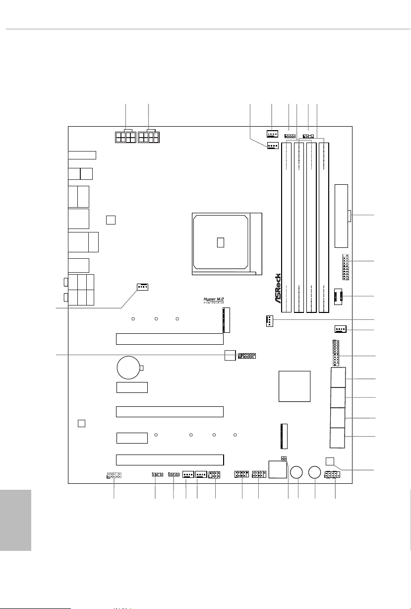
1.3 Motherboard Layout
English
8
Page 16

B550 Taichi Razer Edition
No. Description
1 8 pin 12V Power Connector (ATX12V1)
2 8 pin 12V Power Connector (ATX12V2)
3 CPU/Water Pump Fan Connector (CPU_FAN2/WP_3A)
4 CPU Fan Connector (CPU_FAN1)
5 RGB LED Header (RGB_LED2)
6 2 x 288-pin DDR4 DIMM Slots (DDR4_A1, DDR4_B1)
7 Addressable LED Header (ADDR_LED2)
8 2 x 288-pin DDR4 DIMM Slots (DDR4_A2, DDR4_B2)
9 ATX Power Connector (ATXPWR1)
10 USB 3.2 Gen1 Header (USB3_7_8)
11 Front Panel Type C USB 3.2 Gen2 Header (USB31_TC_2)
12 Chassis/Water Pump Fan Connector (CHA_FAN4/WP)
13 Chassis/Water Pump Fan Connector (CHA_FAN5/WP)
14 USB 3.2 Gen1 Header (USB3_5_6)
15 SATA3 Connectors (SATA3_2) (Upper), (SATA3_1)(Lower)
16 SATA3 Connectors (SATA3_4) (Upper), (SATA3_3)(Lower)
17 SATA3 Connectors (SATA3_A4) (Upper), (SATA3_A3)(Lower)
18 SATA3 Connectors (SATA3_A2) (Upper), (SATA3_A1)(Lower)
19 Clear CMOS Button (CLRCBTN2)
20 System Panel Header (PANEL1)
21 Power Button (PWRBTN1)
22 Reset Button (RSTBTN1)
23 Clear CMOS Jumper (CLRCMOS1)
24 USB 2.0 Header (USB_5_6)
25 USB 2.0 Header (USB_3_4)
26 Power LED and Spea ker Header (SPK_PLED1)
27 Chassis/Water Pump Fan Connector (CHA_FAN1/WP)
28 Chassis/Water Pump Fan Connector (CHA_FAN2/WP)
29 RGB LED Header (RGB_LED1)
30 Addressable LED Header (ADDR _LED1)
31 Front Panel Audio Header (HD_AUDIO1)
32 SPI TPM Header (SPI_TPM_ J1)
33 Chassis/Water Pump Fan Connector (CHA_FAN3/WP)
English
9
Page 17
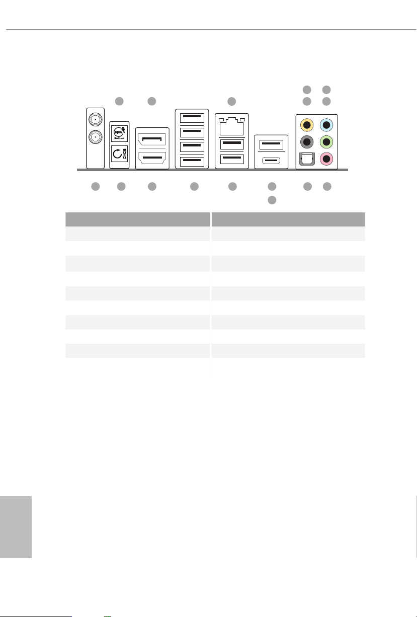
1.4 I/O Panel
1 2
6
3
547
16 12
No. Description No. Description
1 BIOS Flashback Button 10 USB 3.2 Gen2 Type-A Port
2 DisplayPort 1.4 (USB31_TA_1)
3 2.5G LAN RJ-45 Port* 11 USB 3.2 Gen2 Type-C Port
4 Central / Bass (Orange) (USB31_TC_1)
5 Rear Speaker (Black) 12 USB 2.0 Ports (USB2_12)
6 Line In (Light Blue) 13 USB 3.2 Gen1 Ports
7 Front Speaker (Lime)** (USB3_1_4)***
8 Microphone (Pink) 14 HDMI Port
9 Optical SPDIF Out Port 15 Clear CMOS Button
14 1315
11
16 Antenna Ports
8910
English
10
Page 18
B550 Taichi Razer Edition
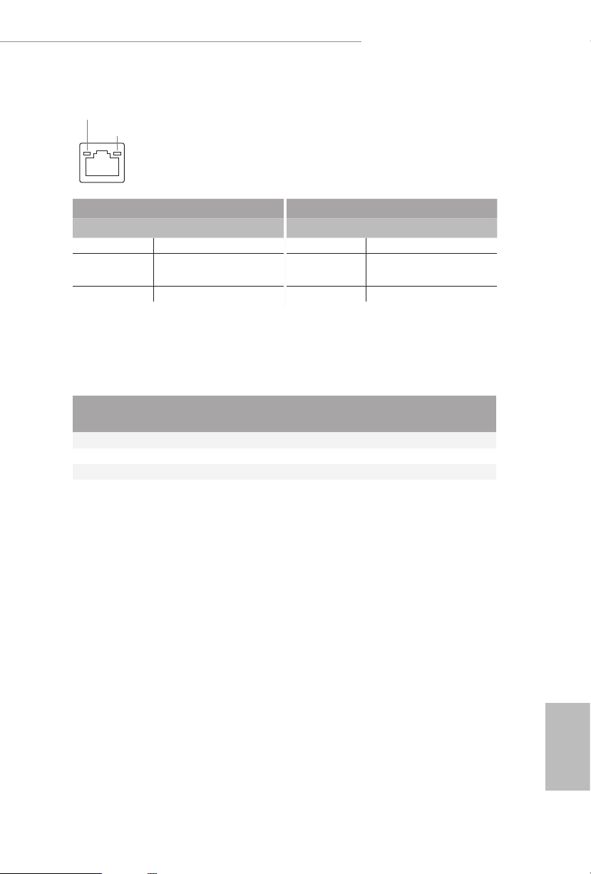
* ere are two LEDs on each LAN port. Ple ase refer to the table below for the LAN port LED indications.
ACT/LINK LED
SPEED LED
LAN Por t
Activity / Link LED Speed LED
Status Description Status Description
O No Link O 10Mbps connection
Blinking Data Activity Orange
On Link Green 2.5Gbps connection
** If you use a 2- channel speaker, please connect the speaker’s plug into “Front Speaker Jack”. See the table below
for connection details in accordance with the type of s peaker you use.
100Mbps/1Gbps
connection
Audio Output
Channels
Front Speaker
(No. 7)
Rear Speaker
(No.5)
Central / Bass
(No. 4)
2 V -- -- --
4 V V -- --
6 V V V --
8 V V V V
*** ACPI wake-up function is not supported on USB3_1_ 2 ports.
Line In
(No. 6)
English
11
Page 19
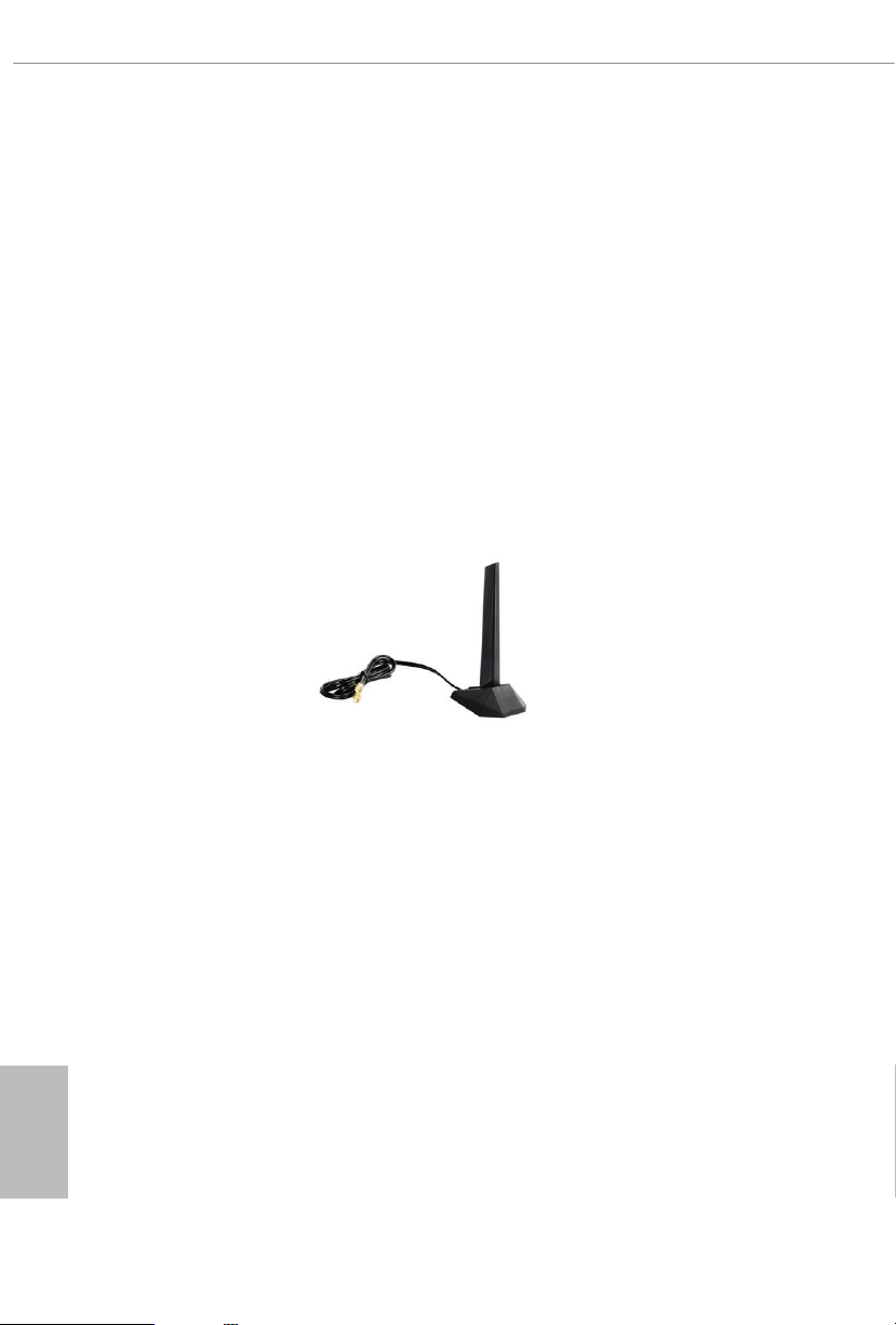
1.5 WiFi-802.11ax Module and ASRock WiFi 2.4/5 GHz
Antenna
WiFi-802.11ax + BT Module
is motherboard comes with an exclusive WiFi 802.11 a/b/g/n/ax + BT v5.1
module (pre-installed on the rear I/O panel) that oers support for WiFi 802.11 a/b/
g/n/ax connectivity standards and Bluetooth v5.1. WiFi + BT module is an easy-to-
use wireless local area network (WLAN) adapter to support WiFi + BT. Bluetooth
v5.1 standard features Smart Ready technology that adds a whole new class of
functionality into the mobile devices. BT 5.1 also includes Low Energy Technology
and ensures extraordinary low power consumption for PCs. e 2T2R WiFi
solution sets a WiFi high speed standard and oers max link rate up to 2.4Gbps.
* e transmission speed may vary according to the environment.
ASRock WiFi 2.4/5 GHz Antenna
English
12
Page 20

B550 Taichi Razer Edition
Chapter 2 Installation
is is an ATX form factor motherboard. Before you install the motherboard, study
the conguration of your chassis to ensure that the motherboard ts into it.
Pre-installation Precautions
Take note of the following precautions before you install motherboard components
or change any motherboard settings.
Make sure to unplug the power cord before installing or removing the motherboard.
•
Failure to do so may cause physical injuries to you and damages to motherboard
components.
In order to avoid damage from static electricity to the motherboard’s components,
•
NEVER place your motherboard directly on a carpet. Also remember to use a grounded
wrist strap or touch a safety grounded object before you handle the components.
Hold components by the edges and do not touch the ICs.
•
Whenever you uninstall any components, place them on a grounded anti-static pad or
•
in the bag that comes with the components.
When placing screws to secure the motherboard to the chassis, please do not over-
•
tighten the screws! Doing so may damage the motherboard.
13
English
Page 21
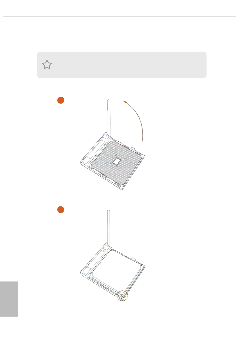
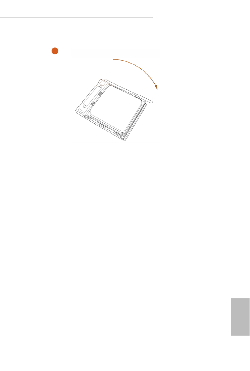
2.1 Installing the CPU
Unplug all power cables before installing the CPU.
1
English
14
2
Page 22
B550 Taichi Razer Edition
3
15
English
Page 23
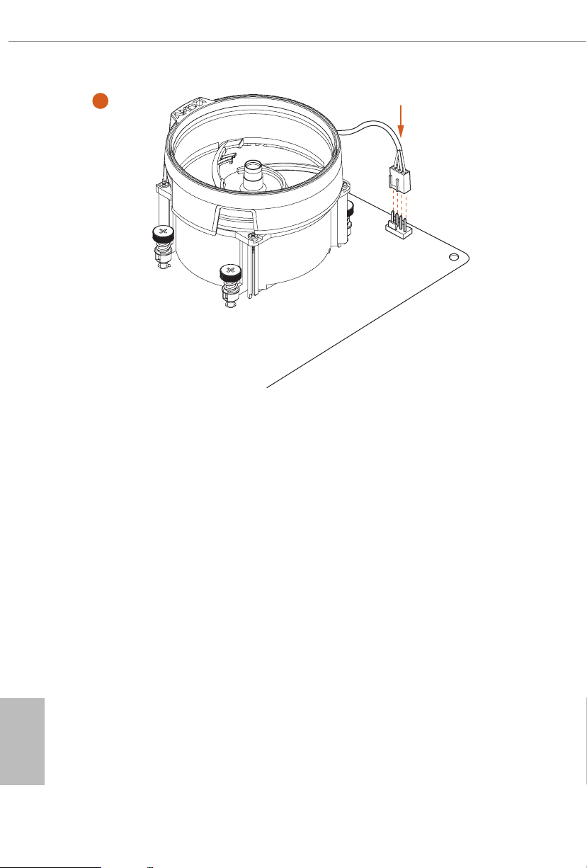
2.2 Installing the CPU Fan and Heatsink
Aer you install the CPU into this motherboard, it is necessary to install a larger
heatsink and cooling fan to dissipate heat. You also need to spray thermal grease
between the CPU and the heatsink to improve heat dissipation. Make sure that the
CPU and the heatsink are securely fastened and in good contact with each other.
Please turn o the power or remove the power cord be fore changing a CPU or heatsink .
Installing the CPU Box Cooler SR1
1
English
16
2
Page 24
B550 Taichi Razer Edition
3
4
1
N
FA
_
U
P
C
English
17
Page 25
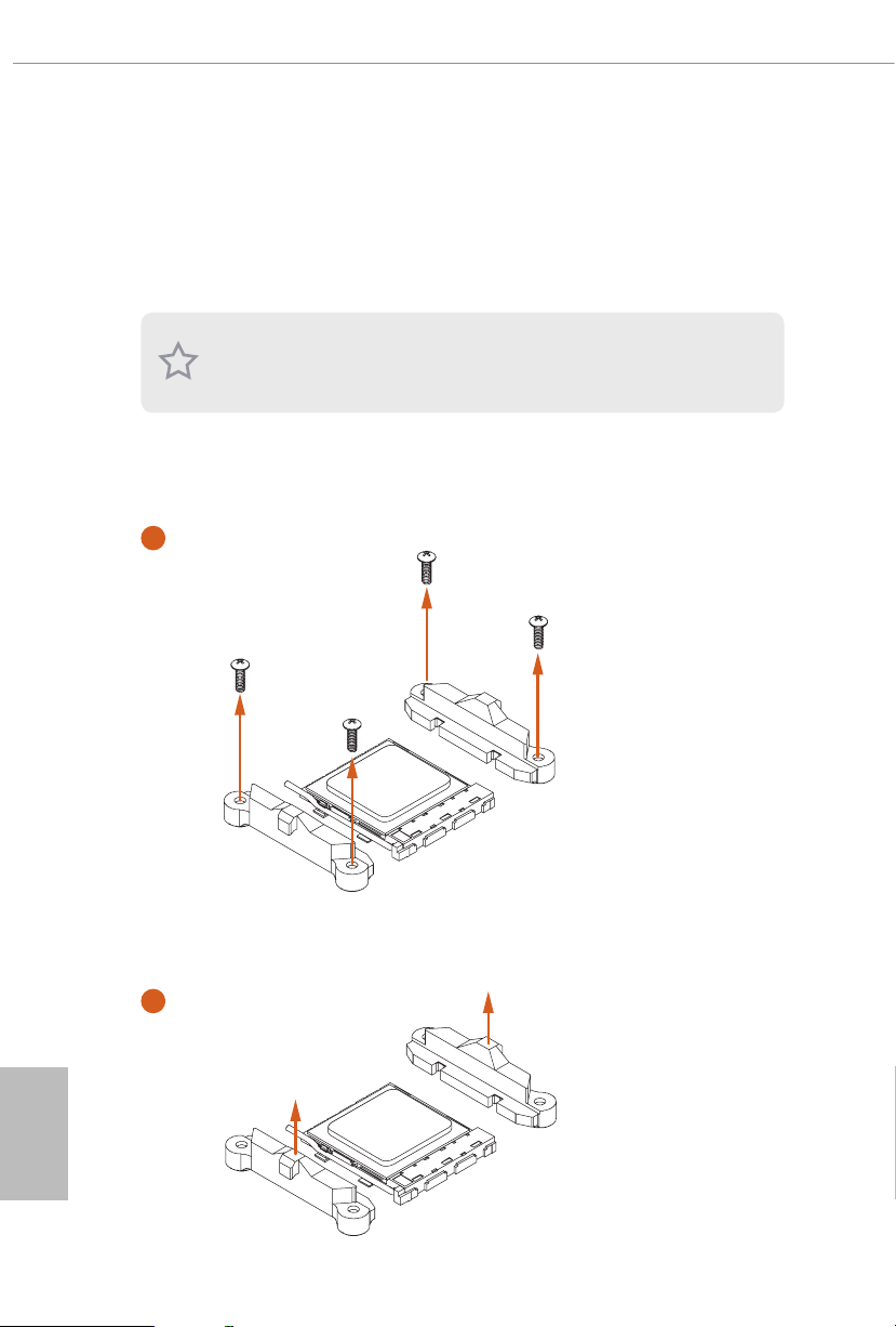
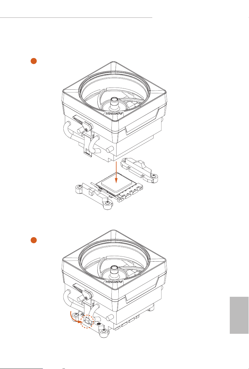
Installing the AM4 Box Cooler SR2
1
2
English
18
Page 26
B550 Taichi Razer Edition
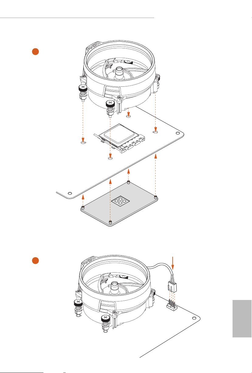
3
19
English
Page 27
4
1
N
FA
_
U
P
C
*e diagrams shown here are for reference only. e headers might be in a dierent position on
your motherboard.
English
20
Page 28
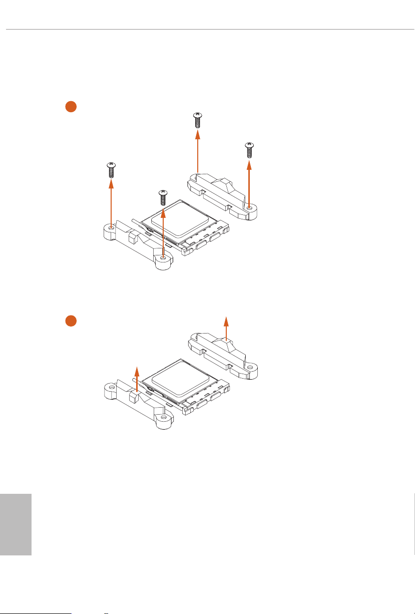
Installing the AM4 Box Cooler SR3
1
B550 Taichi Razer Edition
2
English
21
Page 29
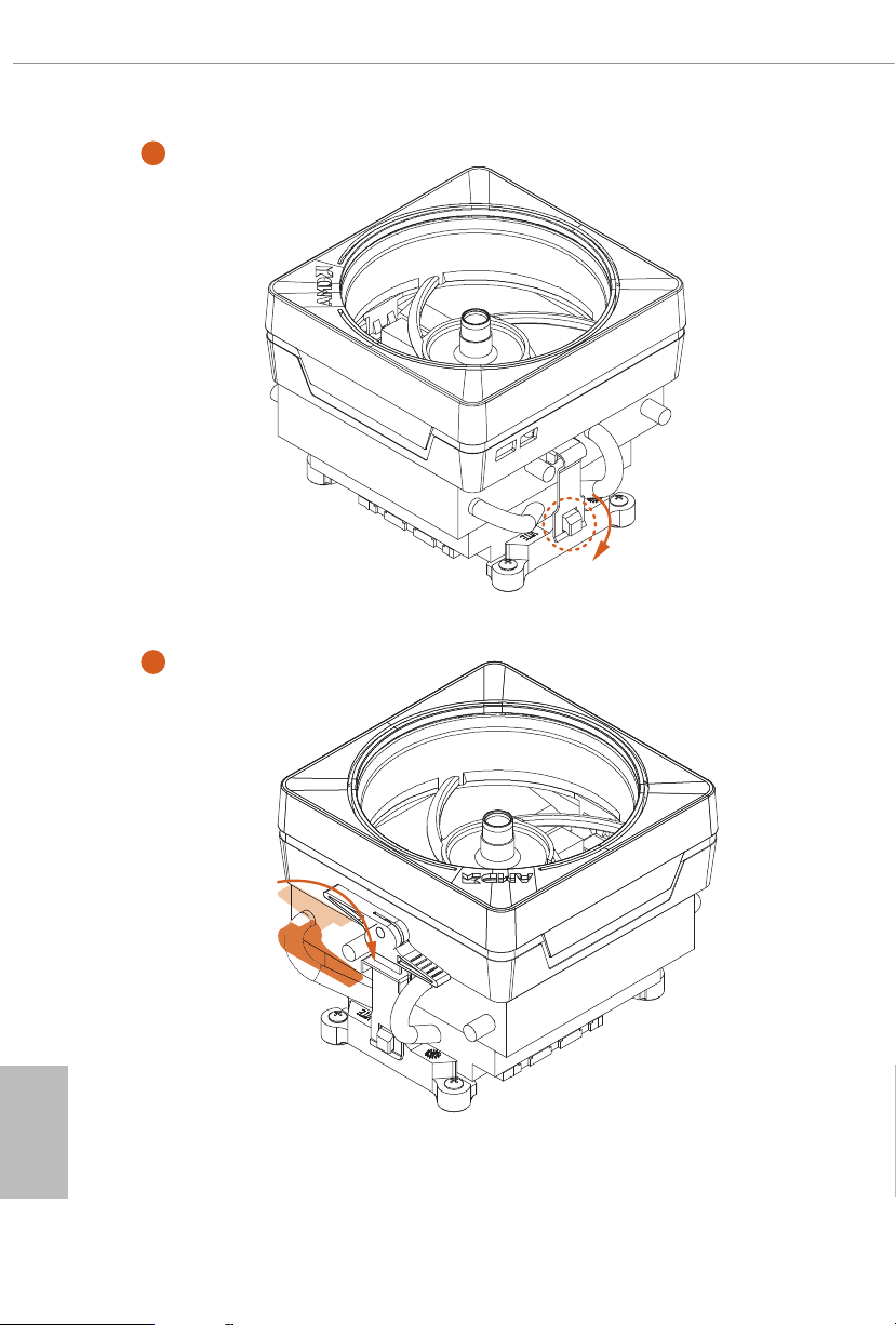
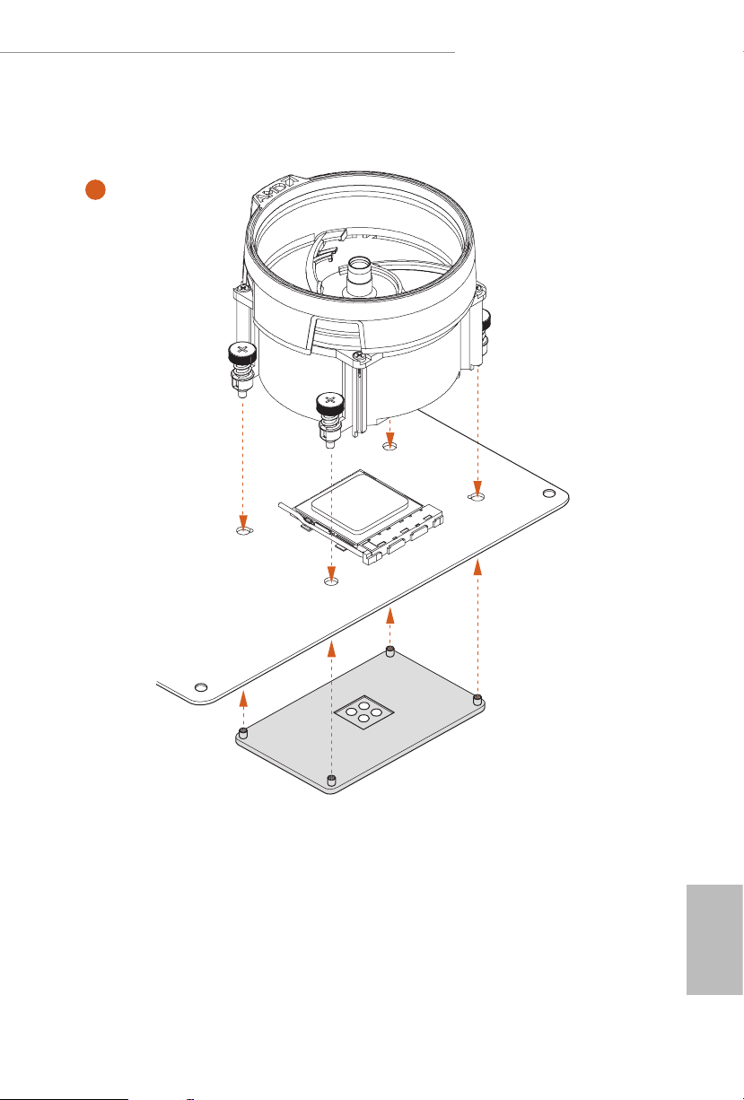
3
4
English
22
Page 30
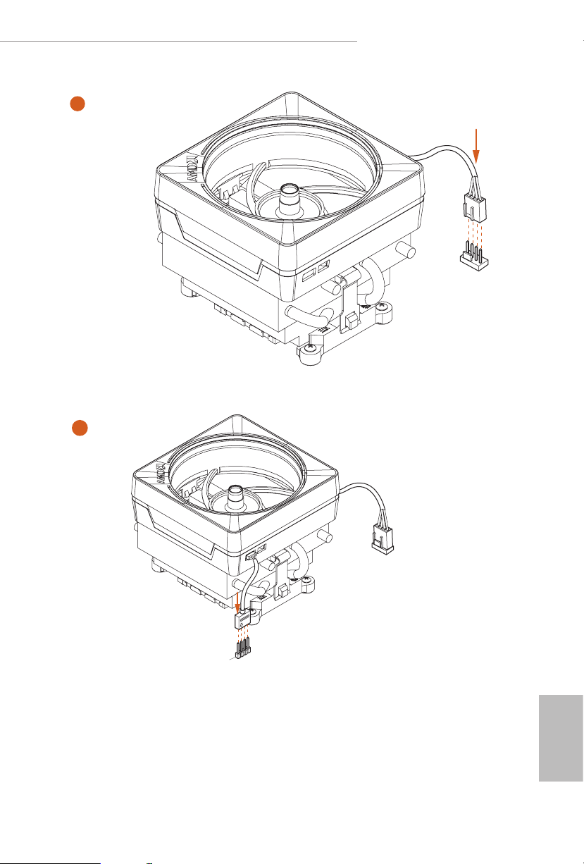
B550 Taichi Razer Edition
5
FAN1
CPU_
6
1
N
FA
_
U
P
C
2
D
E
L
_
B
RG
+12V
*e diagrams shown here are for reference only. e headers might be in a dierent position
on your motherboard.
English
23
Page 31

2.3 Installing Memory Modules (DIMM)
is motherboard provides four 288-pin DDR4 (Double Data Rate 4) DIMM slots,
and supports Dual Channel Memory Technology.
1. For dual channel conguration, you always need to install identical (the same
brand, speed, size and chip-ty pe) DDR4 DIMM pairs.
2. It is unable to activate Dual Channel Memory Technology w ith only one or three
memory module installed.
3. It is not allowed to instal l a DDR, DDR2 or DDR 3 memory modul e into a DDR4
slot; otherwise, thi s motherboard and DIMM may be damaged.
4. We sugge st that you install the memory modules on DDR4_ A2 and DDR4_B2 rst
for better DRA M compatibility on 2 DIMMs conguration.
AMD non-XMP Memory Frequency Support
Ryzen Series CPUs (Vermeer):
English
24
UDIMM Memory Slot
Frequency
A1 A2 B1 B2
- SR - - 3200
- DR - - 3200
- SR - SR 3200
- DR - DR 3200
SR SR SR SR 2933
SR/DR DR SR/DR DR 2667
SR/DR SR/DR SR/DR SR/DR 2667
Ryzen Series CPUs (Matisse):
UDIMM Memory Slot
A1 A2 B1 B2
- SR - - 320 0
- DR - - 3200
- SR - SR 3200
- DR - DR 3200
SR SR SR SR 2933
SR/DR DR SR/DR DR 2667
SR/DR SR/DR SR/DR SR/DR 2667
Frequency
(Mhz)
(Mhz)
Page 32

Ryzen Series APUs (Renoir):
B550 Taichi Razer Edition
UDIMM Memory Slot
A1 A2 B1 B2
- SR - - 320 0
- DR - - 3200
- SR - SR 3200
- DR - DR 3200
SR SR SR SR 2933
SR/DR DR SR/DR DR 2667
SR/DR SR/DR SR/DR SR/DR 2667
SR: Single rank DIMM, 1R x4 or 1Rx8 on DIMM modu le label
DR: Dua l rank DIMM, 2R x4 or 2Rx8 on DIMM module label
Frequency
(Mhz)
25
English
Page 33
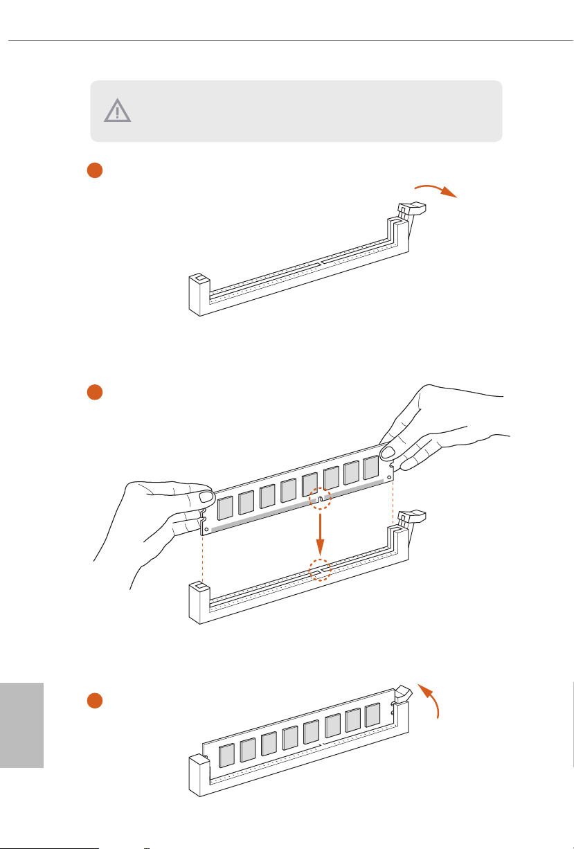
e DIMM only ts in one correct orientation. It will cause permanent damage to
the motherboard and the DIMM if you force the DIMM into the slot at incorrect
orientation.
1
2
English
26
3
Page 34

B550 Taichi Razer Edition
2.4 Expansion Slots (PCI Express Slots)
ere are 5 PCI Express slots on the motherboard.
Before installing an expansion c ard, please mak e sure that the powe r supply is switched o
or the power cord is unplugged. Please read the documentation of the expansion c ard and
make necessary hardware settings for the card before you start the installation.
PCIe slots:
PCIE1 (PCIe 4.0 x16 slot) is used for PCI Express x16 lane width graphics cards.
PCIE2 (PCIe 3.0 x1 slot) is used for PCI Express x1 lane width cards.
PCIE3 (PCIe 4.0 x16 slot) is used for PCI Express x8 lane width graphics cards.
PCIE4 (PCIe 3.0 x1 slot) is used for PCI Express x1 lane width cards.
PCIE5 (PCIe 3.0 x16 slot) is used for PCI Express x4 lane width graphics cards.
* If PCIE2 or PCIE4 is occupied, PCIE5 will downgrade to x2 mode.
PCIe Slot Congurations
Ryzen series CPUs (Vermeer):
PCIE1 PCIE3 PCIE5
Single Graphics Card Gen4x16 N/A N/A
Two Graphics Cards in
CrossFireXTM Mode
ree Graphics Cards in
3-Way CrossFireXTM Mode
Gen4x8 Gen4x8 N/A
Gen4x8 Gen4x8 Gen3x4
English
27
Page 35

Ryzen series CPUs (Matisse):
PCIE1 PCIE3 PCIE5
Single Graphics Card Gen4x16 N/A N/A
Two Graphics Cards in
CrossFireXTM Mode
ree Graphics Cards in
3-Way CrossFireXTM Mode
Gen4x8 Gen4x8 N/A
Gen4x8 Gen4x8 Gen3x4
Ryzen series APUs (Renoir):
PCIE1 PCIE3 PCIE5
Single Graphics Card Gen3x16 N/A N/A
Two Graphics Cards in
CrossFireXTM Mode
ree Graphics Cards in
3-Way CrossFireXTM Mode
For a better ther mal environment , please conne ct a chassis fan to the motherboard’s
chassis fan connector (CHA_FAN1/W P, CHA_FAN2/WP , CHA_FAN3/WP, CHA_FAN4/
WP or CHA_FAN5/WP ) when using multiple graphics cards.
Gen3x8 Gen3x8 N/A
Gen3x8 Gen3x8 Gen3x4
English
28
Page 36

B550 Taichi Razer Edition
2.5 Jumpers Setup
e illustration shows how jumpers are setup. When the jumper cap is placed on
the pins, the jumper is “Short”. If no jumper cap is placed on the pins, the jumper is
“O pen”.
Clear CMOS Jumper
(CLR CMOS1)
(see p.8, No. 23)
CLRCMOS1 allows you to clear the data in CMOS. e data in CMOS includes
system setup information such as system password, date, time, and system setup
parameters. To clear and reset the system parameters to default setup, please
turn o the computer and unplug the power cord, then use a jumper cap to short
the pins on CLRCMOS1 for 3 seconds. Please remember to remove the jumper
cap aer clearing the CMOS. If you need to clear the CMOS when you just nish
updating the BIOS, you must boot up the system rst, and then shut it down
before you do the clear-CMOS action.
e Clear CMOS Button has the same func tion as the Clear CMOS jumpe r.
2-pin Jumper
Short: Clear CMOS
Open: Default
29
English
Page 37

2.6 Onboard Headers and Connectors
1
Onboard headers and connectors are NOT jumpers. Do NOT pla ce jumper caps over these
heade rs and connectors. Plac ing jumper caps over the hea ders and connectors will cause
permanent damage to the motherboard.
System Panel Header
(9-p in PA NE L1)
(see p.8, No. 20)
PWRBTN (Power But ton):
Connec t to the power button on the chassis f ront panel. You may congure the way to turn
o your system using the powe r button.
RESET (Reset Button):
Connec t to the reset button on the chassis f ront panel. Pre ss the reset button to restart the
computer if the computer freezes and fails to perform a normal restart.
PLED (Syste m Power LED):
Connec t to the power status indicator on the chassi s front panel. e LED is on when the
system is operating. e LED keeps blinking when the system is in S1/S3 sleep state. e
LED is o when the system is in S4 sleep state or powered o (S5).
HDLED (Ha rd Drive Activity LED):
Connec t to the hard drive ac tivity LED on the chassis f ront panel. e LED is on when the
hard drive is reading or writing data .
e front panel design may dier by chassis . A front panel module mainly consists of powe r
button, reset button, power LED, hard drive a ctivity LED, speaker and etc. W hen connecting your ch assis front panel module to this header, make sure the wire assig nments and the
pin assignments are matched correctly.
PLED+
PLED-
HDLED-
HDLED+
PWRBTN#
GND
RESET#
GND
GND
Connect the power
button, reset button and
system status indicator on
the chassis to this header
according to the pin
assignments below. Note
the positive and negative
pins before connecting
the cables.
English
30
Page 38

B550 Taichi Razer Edition
1
+5V
DUMMY
PLED+
PLED+
PLED-
DUMMY
SPEAKER
DUMMY
GND
GND
P+
P-
USB_PWR
P+
P-
USB_PWR
1
1
Power LED and Speaker
Header
(7-pin SPK_PLED1)
(see p.8, No. 26)
Serial ATA3 Connectors
Right Angle:
(SATA3_1:
see p.8, No. 15)(Lower)
(SATA3_2:
see p.8, No. 15)(Upper)
(SATA3_3:
see p.8, No. 16)(Lower)
(SATA3_4:
see p.8, No. 16)(Upper)
(SATA3_A1:
see p.8, No. 18)(Lower)
(SATA3_A2:
see p.8, No. 18)(Upper)
(SATA3_A3:
see p.8, No. 17)(Lower)
(SATA3_A4:
see p.8, No. 17)(Upper)
SATA3_2
SATA3_4
SATA3_A4SATA3_A2
Please connect the
chassis power LED and
the chassis speaker to this
header.
ese eight SATA3
connectors support SATA
data cables for interna l
SATA3_1
storage devices with up to
6.0 Gb/s data transfer rate.
SATA3_3
*To minimize the boot
time, use AMD B550
SATA ports (SATA3_1)
for your SSDs.
SATA3_A3SATA3_A1
USB 2.0 Headers
(9-pin USB_3_4)
(see p.8, No. 25)
(9-pin USB_5_6)
(see p.8, No. 24)
USB 3.2 Gen1 Headers
(19-pin USB3_7_8)
(see p.8, No. 10)
IntA_PA_SSRX-
IntA_PA_SSRX+
IntA_PA_SSTX-
IntA_PA_SSTX+
IntA_PA_D-
IntA_PA_D+
Vbus
GND
GND
VbusVbus
IntA_PB_SSRX-
IntA_PB_SSRX+
GND
IntA_PB_SSTX-
IntA_PB_SSTX+
GND
IntA_PB_D-
IntA_PB_D+
Dummy
ere are two headers
on this motherboard.
Each USB 2.0 header can
support two ports.
ere are two headers on
this motherboard. Each
USB 3.2 Gen1 header can
support two ports.
English
31
Page 39

(19-pin USB3_5_6)
1
IntA_PB_SSRX+
A_SSRX+
A_SSTX+
J_SENSE
OUT2_L
1
MIC_RET
PRESENCE#
GND
OUT2_R
MIC2_R
MIC2_L
OUT_RET
ype-C Cable
(see p.8, No. 14)
Dummy
IntA_PB_D+
IntA_PB_D-
IntA_PB_SSTX+
IntA_PB_SSTX-
IntA_PB_SSRX-
VbusV
GND
GND
IntA_PA_D+
IntA_PA_D-
GND
IntA_P
IntA_PA_SSTX-
GND
IntA_P
IntA_PA_SSRX-
VbusV
English
Front Panel Type C USB
3.2 Gen2 Header
(20-pin USB31_TC_2)
(see p.8, No. 11)
ere is one Front
Panel Type C USB 3.2
Gen2 Header on this
motherboard. is header
is used for connecting a
USB T
USB 3.2 Gen2 module for
additional USB 3.2 Gen2
ports.
Front Panel Audio Header
(9-pin HD_AUDIO1)
(see p.8, No. 31)
1. High Denition Audio supports Ja ck Sens ing, but the panel wire on the chassis must support HDA to function correctly. Please follow the instructions in our manual and chassi s
manual to instal l your system.
2. If you use an AC’97 audio panel , please install it to the f ront panel audio header b y the
steps below:
A. Connect Mic_ IN (MIC) to MIC2_ L.
B. Conne ct Audio_R (RIN) to OUT2 _R and Audio_ L (LIN) to OUT2_ L.
C. Connect Ground (GND) to Ground (GND).
D. MIC_ RET and OUT_RET are for the HD audio panel only. You don’t need to connect
them for the AC’97 audio panel.
E. To activate the front mic, go to the “FrontMic” Tab in the Realtek Control panel and
adjust “Recording Volume”.
is header is for
connecting audio devices
to the front audio panel.
32
Page 40
B550 Taichi Razer Edition
FAN_SPEED_CONTROL
1 2 3 4
FAN_SPEED_CONTROL
1 2 3 4
GND
1
GND
1 2 3 4
GND
1 2 3 4
GND
4 3 2 1
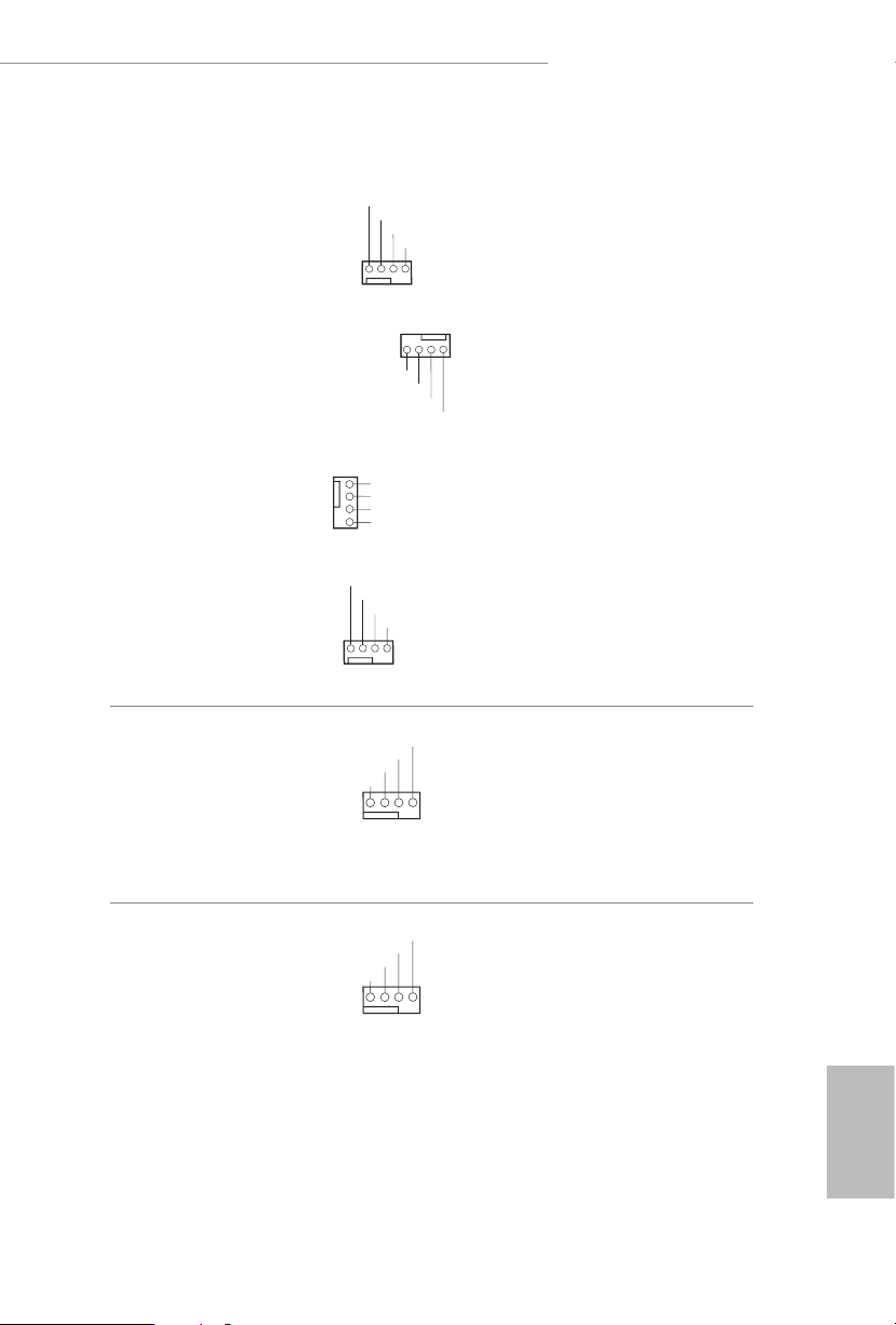
Chassis Water Pump Fan
Connectors
(4-pin CHA_FAN1/WP)
(see p.8, No. 27)
(4-pin CHA_FAN2/WP)
(see p.8, No. 28)
(4-pin CHA_FAN3/WP)
(see p.8, No. 33)
(4-pin CHA_FAN4/WP)
(see p.8, No. 12)
(4-pin CHA_FAN5/WP)
(see p.8, No. 13)
CPU Fan Connector
(4-pin CPU_FAN1)
(see p.8, No. 4)
FAN_VOLTAGE
FAN_SPEED
FAN_SPEED_CONTROL
CHA_FAN_SPEED
FAN_VOLTAGE
FAN_VOLTAGE
2
CHA_FAN_SPEED
3
FAN_SPEED_CONTROL
4
FAN_VOLTAGE
FAN_SPEED
FAN_SPEED_CONTROL
CPU_FAN_SPEED
FAN_VOLTAGE
GND
FAN_SPEED_CONTROL
is motherboard
provides ve 4-Pin water
cooling chassis fan
connectors. If you plan to
connect a 3-Pin
chassis
water cooler fan, please
connect it to Pin 1-3.
is motherboard pro-
vides a 4-Pin CPU fan
(Quiet Fan) connector.
If you plan to connect a
3-Pin CPU fan, please
connect it to Pin 1-3.
CPU Water Pump Fan
Connector
(4-pin CPU_FAN2/
WP_ 3A)
(see p.8, No. 3)
CPU_FAN_SPEED
FAN_VOLTAGE
GND
is motherboard
provides a 4-Pin water
cooling CPU fan
connector. If you plan
to connect a 3-Pin CPU
water cooler fan, please
connect it to Pin 1-3.
English
33
Page 41

ATX Power Connector
1
SPI_DQ3
#
4
1
8 5
(24-pin AT XPWR 1)
(see p.8, No. 9)
12
24
is motherboard pro-
vides a 24-pin ATX power
connector. To use a 20-pin
ATX power supply, please
plug it along Pin 1 and Pin
1
13
13.
ATX 12V Power
Connectors
(8-pin ATX12V1)
(see p.8, No. 1)
(8-pin ATX12V2)
(see p.8, No. 2)
SPI TPM Header
(13 -pi n SPI_TPM _ J1)
(see p.8, No. 32)
+3.3V
SPI_CS0
SPI_DQ2
Dummy
CLK
RSMRST#
SPI_MISO
SPI_MOSI
RST#
TPM_PIRQ
SPI_TPM_CS
GND
is motherboard
provides two 8-pin ATX
12V power connector. To
use a 4-pin ATX power
supply, please plug it along
Pin 1 and Pin 5.
*Connecting an ATX 12V
8-pin cable to ATX12V2 is
optional.
*Warning: Please make
sure that the power cable
connected is for the CPU
and not the graphics
card. Do not plug the
PCIe power cable to this
connec tor.
is connector supports SPI
Trusted Platform Module (TPM)
system, which can securely store
keys, digital certicates, pass-
words, and data. A TPM system
also helps enhance network
security, protects digital
identities, and ensures platform
integr it y.
English
34
Page 42

B550 Taichi Razer Edition
1
1
RGB LED Headers
(4-pin RGB _LED1)
(see p.8, No. 29)
(4-pi n RGB _LE D2)
(see p.8, No. 5)
Addressable LED Headers
(3-pin ADDR _LED1)
(see p.8, No. 30)
(3-pin ADDR _LED2)
(see p.8, No. 7)
+12V GRB
GND
DO_ADDR
VOUT
ese two RGB headers are used
to connect RGB LED extension
cable which allows
users to choose from various LED
lighting eects.
Caution: Never install the RGB
LED cable in the wrong orienta-
tion; otherwise, the cable may
be damaged.
*Please refer to page 66 for
further instructions on these two
headers.
ese two
are used to connect
Addressable
Addressable
headers
LED extension cable which
allows users to choose from
various LED lighting eects.
Caution: Never install the
Addressable LED cable in the
wrong orientation; otherwise,
the cable may be damaged.
*Please refer to page 67 for
further instructions on this
header.
English
35
Page 43

2.7 Smart Switches
e motherboard has ve smart switches: Power Button, Reset Button, Clear CMOS
Buttons and BIOS Flashback Switch, allowing users to quickly turn on/o the
system, reset the system, clear the CMOS values or ash the BIOS.
Power Button
(PWRBTN)
(see p.8, No. 21)
Reset Button
(RSTBTN)
(see p.8, No. 22)
Clear CMOS Buttons
(CLR CBT N1)
(see p.10, No. 15)
(CLRCBTN2)
(see p.8, No. 19)
is function is workabl e only when you power o your computer and unplug the power
supp ly.
Power
Reset
Power Button allows users
to quickly turn on/o the
system.
Reset Button allows
users to quickly reset the
system.
Clear CMOS Buttons
allow users to quickly
clear the CMOS values.
English
36
Page 44

B550 Taichi Razer Edition
BIOS Flashback Button
(BIOS_FB1)
BIOS Flashback Switch allows users
to ash the BIOS.
(see p.10, No. 1)
ASRock BIOS Flashback feature allows you to update BIOS without power ing on the system, even
without CPU.
To use the USB BIOS Flashback f unction, Please follow the steps below.
1. Download the latest BIOS le from ASRock 's website : http://ww w.asrock.com.
2. Copy t he BIOS le to your USB ash d rive. Please make sure the le system of
your USB ash drive must be FAT32.
3. Extract BIOS le from the zip le.
4. Rename the le to “creative.rom” and save it to the root directory of X: USB ash drive.
5. Plug the 24 pin power connector to the motherboard. en turn on t he power supply's AC
switch.
*ere is no need to power on the system.
6. en plug your USB drive to the USB BIOS Flashback port.
7. Press the BIOS Flashback Switch for about three seconds. en the LED starts to blink.
8. Wait unti l the LED stops blinking, indicating that BIOS a shing has been completed.
*If the LED light turns solid green, this means that the BIOS Flashback is not
operating properly. Please make sure that you plug the USB drive to the USB BIOS Flashback
port.
USB BIOS Flashback port
English
37
Page 45

2.8 Dr. Debug
Dr. Debug is used to provide code information, which makes troubleshooting even
easier. Please see the diagrams below for reading the Dr. Debug codes.
Code Description
0x10 PEI_CORE _STARTED
0x11 PEI_CAR_CPU_INIT
0x15 PEI_CAR_NB_INIT
0x19 PEI_CAR_SB_INIT
0x 31 PEI_MEMORY_INSTALLED
0x32 PEI_CPU_INIT
0x33 PEI_CPU_CACHE_INIT
0x34 PEI_CPU_AP_INIT
0x35 PEI_CPU_BSP_SELECT
English
38
0x36 PEI_CPU_SMM_INIT
0x37 PEI_MEM_NB_INIT
0x3B PEI_MEM_SB_INIT
0x4F PEI_DXE_IPL_STARTED
0x60 DXE_CORE_STARTED
0x61 DXE_NVRAM_INIT
0x62 DXE _SBRU N_INI T
Page 46

0x63 DX E_CPU_IN IT
0x68 DXE_NB_HB_INIT
0x69 DXE_NB_INIT
0x6A DXE_NB_SMM_INIT
0x70 DXE _SB_I NIT
0x71 DXE_SB_SMM_INIT
0x72 DXE_SB_DEVICES_INIT
0x78 DXE_ACPI_INIT
0x79 DX E _C SM _INIT
B550 Taichi Razer Edition
0x90 DXE_BDS_STARTED
0x91 DXE_BDS_CONNECT_DRIVERS
0x92 DXE_PCI_BUS_BEGIN
0x93 DXE_PCI_BUS_HPC_INIT
0x94 DXE_PCI_BUS_ENUM
0x95 DXE_PCI_BUS_REQUEST_RESOURCES
0x96 DXE_PCI_BUS_ASSIGN_RESOURCES
0x97 DXE_CON_OUT_CONNECT
0x98 DXE_CON_IN_CONNECT
English
39
Page 47

0x99 DX E_SIO_INIT
0x 9A DXE_USB_BEGIN
0x9B DX E _USB_ RESET
0x9C DXE_USB_DETECT
0x9D DXE_USB_ENABLE
0xA0 DXE_IDE_BEGIN
0xA1 DXE_IDE_RESET
0xA2 DXE _IDE_DETECT
0xA3 DXE_IDE_ENABLE
0xA4 DXE_SCSI_BEGIN
0xA5 DXE_SCSI_ RESET
English
40
0xA6 DXE_SCSI_DETECT
0xA7 DXE_ SCSI _ENA BLE
0xA8 DXE_ SETU P_VER IFYING_ PASSWOR D
0xA9 DXE_SETUP_START
0xAB DXE_SETUP_INPUT_WAIT
0xAD DXE _RE ADY_TO_ BOOT
0xAE DXE_LEGACY_BOOT
Page 48

B550 Taichi Razer Edition
0xAF DX E_EXI T_BOOT_SERVICES
0xB0 RT_SET_VIRTUAL_ADDRESS _MAP_BEGIN
0x B1 RT_SET_VIRTUAL_ADDRESS_MAP_END
0xB2 DXE_L EGACY_OPROM_ INIT
0xB3 DXE_RESET_SYSTEM
0xB4 DXE _USB_HOTPLUG
0xB5 DXE _PCI_BUS_HOTPLUG
0xB6 DXE_NVRAM_CLEANUP
0xB7 DXE _CONFIGURATION_RESET
0xF0 PE I_R ECOV ERY_AUTO
0xF1 PEI_RECOVERY_USER
0xF2 PEI_ RECOVERY_S TARTED
0xF3 PEI_RECOVERY_CAPSULE_FOUND
0xF4 PEI_R ECOVERY_CAPSULE_LOADED
0xE0 PEI_S3_STARTED
0xE1 PEI_S3_BOOT_SCRIPT
0xE2 PEI_S3_VIDEO_REPOST
English
41
Page 49

0xE3 PE I_ S3 _OS _WA KE
0x50 PEI_MEMORY_INVALID_TYPE
0x53 PEI_MEMORY_NOT_DETECTED
0x55 PEI_MEMORY_NOT_INSTALLED
0x57 PEI_CPU_MISMATCH
0x58 PEI_CPU_SELF_TEST_FAILED
0x59 PEI_CPU_ NO_MICROCODE
0x5A PEI_CPU_ERROR
0x5B PEI_RE SET_NOT_AVAILABL E
0xD0 DXE_CPU_ERROR
0x D1 DXE_NB_ERROR
English
42
0xD2 DXE_SB_ERROR
0xD3 DXE_ARCH_PROTOCOL_NOT_AVAILABLE
0xD4 DXE_PCI_BUS_OUT_OF_RESOURCES
0xD5 DXE _LEGACY_OPROM _NO_ SPACE
0xD6 DXE_NO_CON_OUT
0xD7 DXE_NO_CON_IN
Page 50

0xD8 DXE _INVALID_PASSWOR D
0xD9 DXE_BOOT_OPTION_LOAD_ERROR
0x DA DXE_BOOT_OPTION_FAILED
0xDB DXE_FLASH_UPDATE_FAILED
0xDC DXE_RESET_NOT_AVAILABLE
0xE8 PEI_MEMORY_S3_RESUME_FAILED
0xE9 PEI_S3_RESUME_PPI_NOT_FOUND
0xEA PEI _S3_BOOT_ SCRIPT_ER ROR
0xEB PEI_S3_OS_WAKE_ERROR
B550 Taichi Razer Edition
43
English
Page 51

2.9 CrossFireXTM , 3-Way CrossFireXTM and Quad CrossFireXTM
Operation Guide
is motherboard supports CrossFireXTM, 3-way CrossFireXTM and Quad
CrossFireXTM that allows you to install up to three identical PCI Express x16
graphics cards.
1. You should only use identical CrossFireXTM-ready g raphics cards that are AMD
certied.
2. Make sure that your graphics card driver supports AMD CrossFireXTM technology.
Download the dr ivers from the AMD’s website: www.amd.com
3. Make sure that your power supply unit (PSU) can provide at least the minimum
power your system requires. It is recommended to use a AM D certied PSU. Plea se
refer to the AMD’s website for details.
4. If you pair a 12-pipe CrossFireXTM Edition card with a 16-pipe card , both cards will
operate a s 12-pipe cards while in CrossFireXTM mode.
5. Dierent CrossFireXTM cards may require dierent methods to enable CrossFireXTM. Please refer to A MD graphics card manuals for detailed installation guide.
2.9.1 Installing Two CrossFireXTM-Ready Graphics Cards
Step 1
Insert one graphics card into PCIE1 slot
and the other graphics card to PCIE3 slot.
Make sure that the cards are properly
seated on the slots.
English
44
CrossFire Bridge
Step 2
Connect two graphics cards by installing
a CrossFire Bridge on the CrossFire Bridge
Interconnects on the top of the graphics
cards. (e CrossFire Bridge is provided
with the graphics card you purchase, not
bundled with this motherboard. Please
refer to your graphics card vendor for
deta ils.)
Page 52

B550 Taichi Razer Edition
Step 3
Connect a VGA/DVI/DP/HDMI cable from
the monitor to the corresponding port on the
graphics card installed to the PCIE1 slot.
45
English
Page 53

2.9.2 Installing Three CrossFireXTM-Ready Graphics Cards
Step 1
Insert one graphics card into PCIE1 slot,
another graphics card to PCIE3 slot, and
the other graphics card to PCIE5 slot.
Make sure that the cards are properly
seated on the slots.
Step 2
Use one CrossFire Bridge to connect
CrossFire Bridge
the graphics cards on PCIE1 and PCIE3
slots, and use the other CrossFire Bridge
to connect the graphics cards on PCIE3
and PCIE5 slots. (e CrossFire Bridge
is provided with the graphics card
you purchase, not bundled with this
motherboard. Please refer to your graphics
card vendor for details.)
English
46
Step 3
Connect a VGA/DVI/DP/HDMI cable
from the monitor to the corresponding
port on the graphics card installed to the
PCIE1 slot.
Page 54

B550 Taichi Razer Edition
2.9.3 Driver Installation and Setup
Step 1
Power on your computer and boot into OS.
Step 2
Remove the AMD drivers if you have any VGA drivers installed in your system.
e Catalyst Uninstaller i s an optional dow nload . We re commend using this utilit y
to uninstall any previously installed Catalyst dr ivers prior to in stallation. Please
check A MD’s website for AMD dr iver updates.
Step 3
Install the required drivers and CATALYST Control Center then restart your
computer. Please check AMD’s website for details.
Step 4
Double-click the AMD Catalyst Control
AMD Catalyst Control Center
Center icon in the Windows® sy st em tr ay.
Step 5
In the le pane, click Performance and
then AMD CrossFireXTM. en select
Enable AMD CrossFireX and click Apply.
Select the GPU number according to your
graphics card and click Apply.
English
47
Page 55

2.10 M.2_SSD (NGFF) Module Installation Guide (M2_1)
3
The M.2, also known as the Next Generation Form Factor (NGFF), is a small size and
versatile card edge connector t hat aims to replace mPCIe and mSATA. e Hyper M.2
Socket (M2_1) supports M Key ty pe 224 2/2260/2280 M.2 PCI E xpress module up to
Gen4x4 (64 Gb/s) (with Vermeer and Matisse) or Gen3x4 (32 Gb/s) (with Renoir).
Installing the M.2_SSD (NGFF) Module
Step 1
Prepare a M.2_ SSD (NGFF) module
and the screw.
English
2
1
ABC
No. 1 2 3
Nut Location A B C
PCB Length 4.2cm 6cm 8cm
Module Type Type 2 242 Type2 260 Ty pe 22 80
Step 2
Depending on the PCB t ype and
length of your M.2 _SSD (NGFF)
module, nd the corresponding nut
location to be used.
48
Page 56

B550 Taichi Razer Edition
Step 3
1
1
ABC
2
Before installing a M.2 (NGFF) SSD
module, please loosen the screws to
remove the M.2 heatsink.
*Please remove the protective lms
on the bottom side of the M.2
heatsink before you install a M.2
SSD module.
Step 4
Prepare the M.2 stando that comes
with the package. en hand tighten
the stando into the desired nut
location on the motherboard. Align
and gently insert the M.2 (NGFF)
SSD module into the M.2 slot. Please
be aware that the M.2 (NGFF) SSD
module only ts in one orientation.
ABC
o
20
Step 5
Tighten the screw with a screwdriver
to secure the module into place.
NUT1NUT2C
Please do not overtighten the screw
as this might damage the module.
English
49
Page 57

M.2_SSD (NGFF) Module Support List (M2_1)
Vendor Interface P/N
SanDisk PCIe SanDisk-SD6PP4M-128G( Gen2 x2)
Intel PCIe INTEL 6000P-SSDPEKKF256G7 (nvme)
Intel PCIe INTEL 6000P-SSDPEKKF512G7 (nvme)
Intel PCIe SSDPEKKF512G7 NVME / 512GB
Kingston PCIe Kingston SHPM2280P2 / 240G (Gen2 x4)
Samsung PCIe Samsung XP941-MZHPU512HCGL(Gen2x4)
Samsung PCIe SM951 (NVME) / 512GB
Samsung PCIe SM951 (MZHPV512HDGL) / 512GB
ADATA PCIe ASX8000NP-512GM-C / 512GB
ADATA PCIe ASX7000NP-512GT-C / 512GB
Kingston PCIe SKC1000/480G
Kingston PCIe SKC1000/960GB NVME
PLEXTOR PCIe PX-512M8PeG/ 512GB
WD PCIe W DS512G1X0C-00ENX0 (NV ME) / 512GB
For the latest updates of M.2_SSD (NFGG) module support list, please visit our website
for details: http://www.asrock.com
English
50
Page 58

B550 Taichi Razer Edition
4
2.11 M.2_SSD (NGFF) Module Installation Guide (M2_2)
e M.2, also known as the Next Generation Form Factor (NGFF), is a small size and
versatile card edge connector that aims to replace mPCIe and mSATA. e Ultra M.2
Socket (M2_2) supports M Key type 2242/2260/2280/22110 M.2 SATA3 6.0 Gb/s module
and M.2 PCI Express module up to Gen3x4 (32 Gb/s).
Installing the M.2_SSD (NGFF) Module
Step 1
Prepare a M.2_ SSD (NGFF) module
and the screw.
3
2
Depending on the PCB t ype and
length of your M.2 _SSD (NGFF)
module, nd the corresponding nut
Step 2
1
ABCD
location to be used.
No. 1 2 3 4
Nut Location A B C D
PCB Length 4.2cm 6cm 8cm 11cm
Module Type Ty pe 22 42 Ty pe226 0 Type 2280 Ty pe 2211 0
English
51
Page 59

Step 3
1
Before installing a M.2 (NGFF) SSD
module, please loosen the screws to
remove the M.2 heatsink.
*Please remove the protective lms on
1
2
the bottom side of the M.2 heatsink
before you install a M.2 SSD module.
Step 4
Prepare the M.2 stando that comes
with the package. en hand tighten
the stando into the desired nut
ABCD
location on the motherboard. Align
and gently insert the M.2 (NGFF)
SSD module into the M.2 slot. Please
be aware that the M.2 (NGFF) SSD
module only ts in one orientation.
English
52
ABCD
o
20
Step 5
Tighten the screw with a screwdriver
to secure the module into place.
Please do not overtighten the screw as
NUT1NUT2CD
this might damage the module.
Page 60

B550 Taichi Razer Edition
M.2_SSD (NGFF) Module Support List (M2_2)
Vendor Interface P/N
SanDisk PCIe SanDisk-SD6PP4M-128G( Gen2 x2)
Intel PCIe INTEL 6000P-SSDPEKKF256G7 (nvme)
Intel PCIe INTEL 6000P-SSDPEKKF512G7 (nvme)
Intel PCIe SSDPEKKF512G7 NVME / 512GB
Intel SATA 540S-SSDSCKKW240H6 / 240GB
Kingston PCIe Kingston SHPM2280P2 / 240G (Gen2 x4)
Samsung PCIe Samsung XP941-MZHPU512HCGL(Gen2x4)
Samsung PCIe SM951 (NVME) / 512GB
Samsung PCIe SM951 (MZHPV512HDGL) / 512GB
ADATA SATA ADATA - AXNS381E-128GM-B
ADATA PCIe ASX8000NP-512GM-C / 512GB
ADATA PCIe ASX7000NP-512GT-C / 512GB
ADATA SATA ASU800NS38-512GT-C / 512GB
Crucial SATA Crucial-CT240M500SSD4-240GB
ezlink SATA ezlink P51B-80-120GB
Intel SATA INTEL 540S-SSDSCKKW240H6-240GB
Kingston SATA Kingston SM2280S3G2/120G - Win8.1
Kingston SATA Kingston-RBU-SNS8400S3 / 180GD
Kingston PCIe SKC1000/480G
Kingston PCIe SKC1000/960GB NVME
LITEON SATA LITEON LJH-256V2G-256GB (2260)
PLEXTOR SATA PLEXTOR PX-128M6G-2260-128GB
PLEXTOR SATA PLEXTOR PX-128M7VG-128GB
PLEXTOR PCIe PX-512M8PeG/ 512GB
SanDisk SATA SanDisk X400-SD8SN8U-128G
SanDisk SATA Sandisk Z400s-SD8SNAT-128G-1122
SanDisk SATA SanDisk-SD6SN1M-128G
Tra ns ce nd SATA Transcend TS256GMTS800-256GB
Tra ns ce nd SATA TS512GMTS800 / 512GB
V-Co lor SATA V-Color 120 G
V-Co lor SATA V-Color 240G
WD SATA WD GREEN WDS240G1G0B-00RC30
WD PCIe W DS512G1X0C-00ENX0 (NV ME) / 512GB
For the latest updates of M.2_SSD (NFGG) module support list, please visit our website
for details: http://www.asrock.com
English
53
Page 61

Chapter 3 Software and Utilities Operation
3.1 Installing Drivers
e Support CD that comes with the motherboard contains necessary drivers and
useful utilities that enhance the motherboard ’s features.
Running The Support CD
To begin using the support CD, insert the CD into your CD-ROM drive. e CD
automatically displays the Main Menu if “AUTORUN” is enabled in your computer.
If the Main Menu does not appear automatically, locate and double click on the le
“ASRSETUP.EXE” in the Support CD to display the menu.
Drivers Menu
e drivers compatible to your system will be auto-detected and listed on the
support CD driver page. Please click Install All or follow the order from top to
bottom to install those required drivers. erefore, the drivers you install can work
properly.
Utilities Menu
e Utilities Menu shows the application soware that the motherboard supports.
Click on a specic item then follow the installation wizard to install it.
English
54
Page 62

B550 Taichi Razer Edition
3.2 ASRock Motherboard Utility (A-Tuning)
ASRock Motherboard Utility (A-Tuning) is ASRock ’s multi purpose soware suite
with a new interface, more new features and improved utilities.
3.2.1 Installing ASRock Motherboard Utility (A-Tuning)
ASRock Motherboard Utility (A-Tuning) can be downloaded from ASRock Live
Update & APP Shop. Aer the installation, you will nd the icon “ASRock Mother-
board Utility (A-Tuning)“ on your desktop. Double-click the
“ASRock Motherboard Utility (A-Tuning)“ icon, ASRock Motherboard Utility (A-
Tuning ) main menu will pop up.
3.2.2 Using ASRock Motherboard Utility (A-Tuning)
ere are ve sections in ASRock Motherboard Utility (A-Tuning) main menu:
Operation Mode, OC Tweaker, System Info, FAN-Tastic Tuning and Settings.
Operation Mode
Choose an operation mode for your computer.
55
English
Page 63

OC Tweaker
Congurations for overclocking the system.
System Info
View information about the system.
*e System Browser tab may not appear for certain models.
English
56
Page 64

B550 Taichi Razer Edition
FAN-Tastic Tuning
Congure up to ve dierent fan speeds using the graph. e fans will automatically shi
to the next speed level when the assigned temperature is met.
Settings
Congure ASRock ASRock Motherboard Utility (A-Tuning). Click to select "Auto
run at Windows Startup" if you want ASRock Motherboard Utility (A-Tuning) to
be launched when you start up the Windows operating system.
English
57
Page 65

3.3 ASRock Live Update & APP Shop
e ASRock Live Update & APP Shop is an online store for purchasing and
downloading soware applications for your ASRock computer. You can quickly and
easily install various apps and support utilities. With ASRock Live Update & APP
Shop, you can optimize your system and keep your motherboard up to date simply
with a few clicks.
Double-click on your desktop to access ASRock Live Update & APP Shop
utility.
*You need to be connected to the Internet to dow nload apps from the ASRock Live Update & APP Shop.
3.3.1 UI Overview
Category Panel
Hot News
English
58
Information Panel
Category Panel: e category panel contains several category tabs or buttons that
when selected the information panel below displays the relative information.
Information Panel: e information panel in the center displays data about the
currently selected category and allows users to perform job-related tasks.
Hot News: e hot news section displays the various latest news. Click on the image
to visit the website of the selected news and know more.
Page 66

B550 Taichi Razer Edition
3.3.2 Apps
When the "Apps" tab is selected, you will see all the available apps on screen for you
to download.
Installing an App
Step 1
Find the app you want to install.
e most recommended app appears on the le side of the screen. e other various
apps are shown on the right. Please scroll up and down to see more apps listed.
You can check the price of the app and whether you have already intalled it or not.
- e red icon displays the price or "Free" if the app is free of charge.
- e green "Installed" icon means the app is installed on your computer.
Step 2
Click on the app icon to see more details about the selected app.
English
59
Page 67

Step 3
If you want to install the app, click on the red icon to start downloading.
Step 4
When installation completes, you can nd the green "Installed" icon appears on the
upper right corner.
English
60
To uninstall it, simply click on the trash can icon .
*e trash icon may not appear for certain apps.
Page 68

B550 Taichi Razer Edition
Upgrading an App
You can only upgrade the apps you have already installed. When there is an
available new version for your app, you will nd the mark of "New Version"
appears below the installed app icon.
Step 1
Click on the app icon to see more details.
Step 2
Click on the yellow icon to start upgrading.
English
61
Page 69

3.3.3 BIOS & Drivers
Installing BIOS or Drivers
When the "BIOS & Drivers" tab is selected, you will see a list of recommended or
critical updates for the BIOS or drivers. Please update them all soon.
Step 1
Please check the item information before update. Click on to see more details.
Step 2
English
62
Click to select one or more items you want to update.
Step 3
Click Update to start the update process.
Page 70

B550 Taichi Razer Edition
3.3.4 Setting
In the "Setting" page, you can change the language, select the server location, and
determine if you want to automatically run the ASRock Live Update & APP Shop
on Windows startup.
63
English
Page 71

3.4 Nahimic Audio
Nahimic audio soware provides an incredible high denition sound technology which
boosts the audio and voice performance of your system. Nahimic Audio interface is
composed of four tabs: Audio, Microphone, Sound Tracker and Settings.
ere are four functions in Nahimic audio :
No. Function Description
From this tab, you can mute the current audio device, choose
Audio
1
between four factory audio proles, turn all audio eects
on/o, restores the current prole to its default settings and
access Surround Sound and various features.
English
64
Microphone
2
3
4
Sound
Tracker
Settings
From this tab, you can mute the current mic device, choose
between two factory mic proles, turn/o all microphone
eects, restore the current prole to its default settings, and
access Static Noise Suppression and various features.
e Sound Tracker provides a visual indication localizing
the sources of the sounds while in a game. ese are
represented by dynamic segments pointing the direction
of the sounds: the more opaque they are, the stronger the
sounds are.
From this tab, you can access all settings and information of
the soware.
Page 72

B550 Taichi Razer Edition
3.5 Razer Synapse 3
RAZER CHROMA
Razer Synapse 3 allows you to customize the lighting on your motherboard and other
Addressable RGB (ARGB) devices connected to the motherboard’s headers. To set up,
follow these steps:
1. Plug your ARGB LED strips or devices to any of the 3-pin 5V ARGB headers on the
motherboard.
2. Download Razer Synapse 3 from razer.com/synapse then install and login.
3. Use Razer Synapse 3 to access in-depth lighting customization options; and integrate
games and applications across your ARGB and Razer Chroma-enabled devices for a truly
immersive experience.
65
English
Page 73

Connecting the LED Strip
1
1
Connect your RGB LED strips to the
motherboard.
RAZER EDITION
B55O Taic hi
RGB LED Headers (RGB_LED1, RGB_L ED2)
RGB_LED2
on the
English
+12V GRB
1
B
R
G
V
2
1
RGB_LED1
+12V GRB
1. Never install the RGB LED cable in the wrong orientation; otherwise, the cable may be
damaged.
2. Before installing or removing your RGB LED cable, please powe r o your system and
unplug the power cord from the power supply. Failure to do so may cause damages to
motherboard components.
1. Please note that the RGB LED strips do not come with the package.
2. e RGB LED header suppor ts standard 5050 RGB LED strip (12V/G/R/B), with a
maximum power rating of 3A (12V) and leng th within 2 meters.
66
Page 74

Connecting the Addressable RGB LED Strip
D
1
D
1
Connect your
ADDR _LED2)
Addressable RGB LED
on the motherboard.
RAZER EDITION
B55O Tai chi
strips to the
Addressable LED Headers (ADDR_LED1,
ADDR_LED2
VOUT
GN
DO_ADDR
B550 Taichi Razer Edition
ADDR_LED1
DO_ADDR
VOUT
1
GN
1. Never install the RGB LED cable in the wrong orientation; otherwise, the cable may be
damaged.
2. Before installing or removing your RGB LED cable, please powe r o your system and
unplug the power cord from the power supply. Failure to do so may cause damages to
motherboard components.
1. Please note that the RGB LED strips do not come with the package.
2. e RGB LED header suppor ts WS2812B addressable RGB LED strip (5V/Data/
GND), with a ma ximum power rating of 3A (5V) and length within 2 meters.
English
67
Page 75
Chapter 4 UEFI SETUP UTILITY
4.1 Introduction
is section explains how to use the UEFI SETUP UTILITY to congure your
system. You may run the UEFI SETUP UTILITY by pressing <F2> or <Del> right
aer you power on the computer, otherwise, the Power-On-Self-Test (POST) will
continue with its test routines. If you wish to enter the UEFI SETUP UTILITY aer
POST, restart the system by pressing <Ctl> + <Alt> + <Delete>, or by pressing the
reset button on the system chassis. You may also restart by turning the system o
and then back on.
Becau se the UEFI soware is cons tantly being updated, the following UEFI setup
screens and descriptions are for reference purpose only, and they may not e xactly
match what you see on your screen.
4.1.1 UEFI Menu Bar
e top of the screen has a menu bar with the following selections:
English
68
Main
OC Tweaker
Advanced
Tool
H/W Monitor
Security
Boot
Exit
For setting system time/date information
For overclocking congurations
For advanced system congurations
Useful tools
Displays current hardware status
For security settings
For conguring boot settings and boot priority
Exit the current screen or the UEFI Setup Utility
Page 76

B550 Taichi Razer Edition
4.1.2 Navigation Keys
Use < > key or < > key to choose among the selections on the menu bar, and
use < > key or < > key to move the cursor up or down to select items, then
press <Enter> to get into the sub screen. You can also use the mouse to click your
required item.
Please check the following table for the descriptions of each navigation key.
Navigation Key(s) Description
+ / -
<Tab>
<PGUP>
<PGDN>
<HOME>
<END>
<F1>
<F7>
<F9>
<F10>
<F12>
<ESC>
To change option for the selected items
Switch to next function
Go to the previous page
Go to the next page
Go to the top of the screen
Go to the bottom of the screen
To display the General Help Screen
Discard changes and exit the SETUP UTILITY
Load optimal default values for all the settings
Save changes and exit the SETUP UTILITY
Print screen
Jump to the Exit Screen or exit the current screen
69
English
Page 77

4.2 Main Screen
When you enter the UEFI SETUP UTILITY, the Main screen will appear and
display the system overview.
English
70
Page 78

4.3 OC Tweaker Screen
In the OC Tweaker screen, you can set up overclocking features.
B550 Taichi Razer Edition
Becau se the UEFI soware is cons tantly being updated, the following UEFI setup
screens and descriptions are for reference purpose only, and they may not e xactly
match what you see on your screen.
Overclock Mode(Bus Speed)
Select the overclock mode. Warning! When overclocking also the PCIe, PCI, SATA and
USB busses will be overcloked which may cause instability or failure. Please install an
operating system and the drivers required before overclocking, or else your HDD's may be
undetectable. Overclocking is not supported if the monitor is connected via the onboard
D-Bus/VGA connector.
CPU Frequency and Voltage(VID) Change
If this item is set to [Manual], the multiplier and voltage will be set based on user selection.
Final result is depending on the CPU's capability.
CPU Core (Per CCX)
CPU Voltage
Species a custom CPU core voltage, Should be combined with a custom CPU core
frequency. Power saving features for idle cores (e.g. cc6 sleep) remain active.
English
71
Page 79

CCD0
CCX0 Frequency (MHz)
Use this item to adjust CCX0 Frequency.
CCX1 Frequency (MHz)
Use this item to adjust CCX1 Frequency.
CCD1
CCX0 Frequency (MHz)
Use this item to adjust CCX0 Frequency.
CCX1 Frequency (MHz)
Use this item to adjust CCX1 Frequency.
SoC/Uncore OC Voltage(VID)
Specify the SoC/Uncore voltage (VDD_SOC) in mV to support memory and Innity Fabric
overclocking. VDD_SOC also determines the GPU voltage on processors with integrated
graphics. “SoC/Uncore OC Mode” needs to be enabled to force this voltage.
CLD0 VDDP Voltage Control
AMD Overclocking Setup VDDP is a voltage for the DDR4 bus signaling (PHY), and it is
derived from your DRAM Voltage (VDDIO_Mem). As a result, VDDP voltage in mV can
approach but not exceed your DRAM Voltage.
English
72
CLD0 VDDG CCD Voltage Control
AMD Overclocking Setup VDDG CCD represents voltage for the data portion of the Innity
Fabric. It is derived from the CPU SoC/Uncore Voltage (VDD_SOC). VDDG can approach
but not exceed VDD_SOC.
CLD0 VDDG IOD Voltage Control
AMD Overclocking Setup VDDG IOD represents voltage for the data portion of the Innity
Fabric. It is derived from the CPU SoC/Uncore Voltage (VDD_SOC). VDDG can approach
but not exceed VDD_SOC.
Page 80

B550 Taichi Razer Edition
DRAM Information
Load XMP Setting
Load XMP settings to overclock the memory and perform beyond standard
specications.
DRAM Frequency
If [Auto] is selected, the motherboard will detect the memory module(s) inserted
and assign the appropriate frequency automatically. Setting DR AM Frequency can
adjust DRAM Timing.
DRAM Voltage
Congure the voltage for the DRAM Voltage.
Innity Fabric Frequency and Dividers
AMD Overclocking Setup Set Innity Fabric frequency (FCLK). Auto: FCLK =
MCLK. Manual: FCLK must be less than or equal to MCLK for best performance in
most cases. Latency penalties are incurred if FCLK and MCLK are mismatched, but
suciently high MCLK can negate or overcome this penalty.
DRAM Timing Conguration
External Voltage Settings and Load-line Calibration
Voltage Mode
[OC]
If this option is selected, there is larger range voltage for overclocking.
[Normal]
If this option is selected, there is smaller range voltage for normal system.
CPU Core/Cache Voltage
Input voltage for the processor by the external voltage refulator.
CPU Core/Cache Load-Line Calibration
CPU Core/Cache Load-Line Calibration helps prevent CPU voltage droop when the
system is under heavy loading.
CPU VDDCR_SOC Voltage
Congure the voltage for the VID-requested VDDCR _SOC supply level.
English
73
Page 81

CPU VDDCR_SOC Load-Line Calibration
CPU VDDCR_SOC Load-Line Calibration helps prevent VDDCR_SOC voltage
droop when the system is under heav y loading
VPPM
Congure the voltage for the VPPM.
VTT_DDR Oset Voltage(mV)
Congure the voltage for the VTT_DDR Oset Voltage(mV).
CPU VDD 1.8V Voltage
Congure the voltage for the CPU VDD 1.8V Voltage. e default value is [Auto].
Save User Default
Type a prole name and press enter to save your settings as user default.
Load User Default
Load previously saved user defaults.
Save User UEFI Setup Prole to Disk
It helps you to save current UEFI settings as an user prole to disk.
Load User UEFI Setup Prole from Disk
You can load previous saved prole from the disk.
English
74
Page 82

B550 Taichi Razer Edition
4.4 Advanced Screen
In this section, you may set the congurations for the following items: CPU
Conguration, Onboard Devices Conguration, Storage Conguration, ACPI Con-
guration, Trusted Computing, AMD PBS, AMD Overclocking and AMD CBS.
Setting wrong values in this section may cause the system to malf unction.
UEFI Conguration
Active Page on Entry
Select the default page when entering the UEFI setup utility.
Full HD UEFI
When [Auto] is selected, the resolution will be set to 1920 x 1080 if the monitor
supports Full HD resolution. If the monitor does not support Full HD resolution,
then the resolution will be set to 1024 x 768. When [Disable] is selected, the
resolution will be set to 1024 x 768 directly.
English
75
Page 83

4.4.1 CPU Conguration
PSS Support
Use this to enable or disable the generation of ACPI_PPC, _PSS, and _PCT objects.
NX Mode
Use this to enable or disable NX mode.
English
76
SVM Mode
When this is set to [Enabled], a VMM (Virtual Machine Architecture)can utilize the
additional hardware capabilities provided by AMD-V. e default value is [Enabled].
Coniguration options: [Enabled] and [Disabled].
SMT Mode
is item can be used to disable symmetric multithreading. To re-enable SMT, a
power cycle is needed aer selecting [Auto].
Warning: S3 is not supported on systems where SMT is disabled.
AMD fTPM Switch
Use this to enable or disable AMD CPU fTPM.
Page 84

4.4.2 Onboard Devices Conguration
Turn On LED in S5
Turn on LED in the ACPI S5 state.
Restore Onboard LED Default
Restore Onboard LED default value.
B550 Taichi Razer Edition
RGB LED On/O
is option enables/disables the RGB LED
.
SR-IOV Support
Enable/disable the SR-IOV (Single Root IO Virtualization Support) if the system
has SR-IOV capable PCIe devices.
UMA Frame buer Size
is item allows you to set the size of the UMA frame buer.
(Only for processor with integrated graphics)
Gnb HD Audio
Enable/disable onboard HD audio. Set to Auto to enable onboard HD audio and
automatically disable it when a sound card is installed.
Front Panel
Enable/disable front panel HD audio.
Restore on AC/Power Loss
Select the power state aer a power failure. If [Power O] is selected, the power will
remain o when the power recovers. If [Power On] is selected, the system will start
to boot up when the power recovers.
English
77
Page 85

WAN Radio
Congure the WiFi module's connectivity.
BT On/O
Enable/disable the bluetooth.
Onboard LAN
Enable or disable the onboard network interface controller.
PCIE Redriver
EQ1_T X
Congure EQ1_TX.
EQ2_TX
Congure EQ2_TX.
EQ3_TX
Congure EQ3_TX.
Swing Setting and Flat Gain Setting (SFA_TX)
Congure Swing Setting and Flat Gain Setting (SFA_TX).
Swing Setting and Flat Gain Setting (SFB_TX)
Congure Swing Setting and Flat Gain Setting (SFB_TX).
English
78
EQ1_ RX
Congure EQ1_RX.
EQ2_RX
Congure EQ2_RX.
EQ3_RX
Congure EQ3_RX.
Swing Setting and Flat Gain Setting (SFA_RX)
Congure Swing Setting and Flat Gain Setting (SFA_RX).
Swing Setting and Flat Gain Setting (SFB_RX)
Congure Swing Setting and Flat Gain Setting (SFB_R X).
Page 86

4.4.3 Storage Conguration
SATA Mode
AHCI: Supports new features that improve performance.
B550 Taichi Razer Edition
RAID: Combine multiple disk drives into a logical unit.
SATA Hot Plug
Enable/disable the SATA Hot Plug function.
English
79
Page 87

4.4.4 ACPI Conguration
Suspend to RAM
It is recommended to select auto for ACPI S3 power saving.
Deep Sleep
Congure deep sleep mode for power sav ing when the computer is shut down.
English
80
PCIE Devices Power On
Allow the system to be waked up by a PCIE device and enable wake on LAN.
RTC Alarm Power On
Allow the system to be waked up by the real time clock alarm. Set it to By OS to let
it be handled by your operating system.
USB Power Delivery in Soft O State (S5)
If this option is enabled, the USB port will provide power to your devices even when
the system is in Power State S5.
Page 88

4.4.5 Trusted Computing
Security Device Support
Enable or disable BIOS support for security device.
B550 Taichi Razer Edition
81
English
Page 89

4.4.6 AMD PBS
e AMD PBS menu accesses AMD specic features.
English
82
Page 90

B550 Taichi Razer Edition
4.4.7 AMD Overclocking
e AMD Overclocking menu accesses options for conguring CPU frequency and
voltage.
83
English
Page 91

4.4.8 AMD CBS
e AMD CBS menu accesses AMD specic features.
English
84
Page 92

4.5 Tools
RGB LED
RGB LED allows you to turn on/o this feature.
B550 Taichi Razer Edition
Easy RAID Installer
Easy R AID Installer helps you to copy the RAID driver from the support CD to
your USB storage device. Aer copying the drivers please change the SATA mode to
RAID, then you can start insta lling the operating system in RAID mode.
SSD Secure Erase Tool
Use this tool to securely erase SSD.
NVME Sanitization Tool
Aer you sanitize SSD, all user data will be permantly destroyed on the SSD and
cannot be recovered.
Instant Flash
Save UEFI les in your USB storage device and run Instant Flash to update your
UEFI.
English
85
Page 93

4.6 Hardware Health Event Monitoring Screen
is section allows you to monitor the status of the hardware on your system,
including the parameters of the CPU temperature, motherboard temperature, fan
speed and voltage.
CPU FAN1 Setting
Select a fan mode for CPU Fan 1, or choose Customize to set 5 CPU temperatures
and assign a respective fan speed for each temperature.
English
86
CPU FAN1 Temp Source
Select a fan temperature source for CPU Fan 1.
FAN Conguration
CPU_FAN2/WP Switch
Select CPU Water Pump mode.
CPU Fan 2 Control Mode
Select PWM mode or DC mode for CPU Fan 2 .
CPU Fan 2 Setting
Select a fan mode for CPU Fan 2, or choose Customize to set 5 CPU temperatures
and assign a respective fan speed for each temperature.
Page 94

B550 Taichi Razer Edition
CPU Fan 2 Temp Source
Select a fan temperature source for CPU Fan 2.
CPU_ FAN2 On/O
Set CPU_FAN2 to On or O.
CHA_FAN1/WP Switch
Select CHA_FAN1 or Water Pump mode.
Chassis Fan 1 Control Mode
Select PWM mode or DC mode for Chassis Fan 1 .
Chassis Fan 1 Setting
Select a fan mode for Chassis Fan 1, or choose Customize to set 5 CPU temperatures
and assign a respective fan speed for each temperature.
Chassis Fan 1 Temp Source
Select a fan temperature source for Chassis Fan 1.
CHA_FAN2/WP Switch
Select CHA_FAN2 or Water Pump mode.
Chassis Fan 2 Control Mode
Select PWM mode or DC mode for Chassis Fan 2 .
Chassis Fan 2 Setting
Select a fan mode for Chassis Fan 2, or choose Customize to set 5 CPU temperatures
and assign a respective fan speed for each temperature.
Chassis Fan 2 Temp Source
Select a fan temperature source for Chassis Fan 2.
CHA_FAN3/WP Switch
Select CHA_FAN3 or Water Pump mode.
Chassis Fan 3 Control Mode
Select PWM mode or DC mode for Chassis Fan 3 .
English
87
Page 95

Chassis Fan 3 Setting
Select a fan mode for Chassis Fan 3, or choose Customize to set 5 CPU temperatures
and assign a respective fan speed for each temperature.
Chassis Fan 3 Temp Source
Select a fan temperature source for Chassis Fan 3.
CHA_FAN4/WP Switch
Select CHA_FAN4 or Water Pump mode.
Chassis Fan 4 Control Mode
Select PWM mode or DC mode for Chassis Fan 4.
Chassis Fan 4 Setting
Select a fan mode for Chassis Fan 4, or choose Customize to set 5 CPU temperatures
and assign a respective fan speed for each temperature.
Chassis Fan 4 Temp Source
Select a fan temperature source for Chassis Fan 4.
CHA_FAN5/WP Switch
Select CHA_FAN5 or Water Pump mode.
Chassis Fan 5 Control Mode
English
88
Select PWM mode or DC mode for Chassis Fan 5.
Chassis Fan 5 Setting
Select a fan mode for Chassis Fan 5, or choose Customize to set 5 CPU temperatures
and assign a respective fan speed for each temperature.
Chassis Fan 5 Temp Source
Select a fan temperature source for Chassis Fan 5.
Fan-Tasti c
Select a fan mode for Fan, or choose Customize to set 5 CPU temperatures and assign a
respective fan speed for each temperature.
FanTuning
Detect the lowest fan speed in the system. Iy may take 3-5 minutes to complete.
Page 96

B550 Taichi Razer Edition
4.7 Security Screen
In this section you may set or change the super visor/user password for the system.
You may also clear the user password.
Supervisor Password
Set or change the password for the administrator account. Only the administrator
has authority to change the settings in the UEFI Setup Utility. Leave it blank and
press enter to remove the password.
User Password
Set or change the password for the user account. Users are unable to change the
settings in the UEFI Setup Utility. Leave it blank and press enter to remove the
password.
Secure Boot
Enable to support Secure Boot.
English
89
Page 97

4.8 Boot Screen
is section displays the available devices on your system for you to congure the
boot settings and the boot priority.
Boot From Onboard LAN
Allow the system to be waked up by the onboard LAN.
Setup Prompt Timeout
Congure the number of seconds to wait for the setup hot key.
English
90
Fast Boot
Fast Boot minimizes your computer's boot time. In fast mode you may not boot
from an USB storage device.
Bootup Num-Lock
Select whether Num Lock should be turned on or o when the system boots up.
Full Screen Logo
Enable to display the boot logo or disable to show normal POST messages.
AddOn ROM Display
Enable AddOn ROM Display to see the AddOn ROM messages or congure the Ad-
dOn ROM if you’ve enabled Full Screen Logo. Disable for faster boot speed.
Page 98

B550 Taichi Razer Edition
CSM (Compatibility Support Module)
CSM
Enable to launch the Compatibility Support Module. Please do not disable unless
you’re running a WHCK test.
Launch PXE OpROM Policy
Select UEFI only to run those that support UEFI option ROM only. Select Legacy
only to run those that support legacy option ROM only. Select Do not launch to not
execute both legacy and UEFI option ROM.
Launch Storage OpROM Policy
Select UEFI only to run those that support UEFI option ROM only. Select Legacy
only to run those that support legacy option ROM only. Select Do not launch to not
execute both legacy and UEFI option ROM.
English
91
Page 99

4.9 Exit Screen
Save Changes and Exit
When you select this option the following message, “Save conguration changes
and exit setup?” will pop out. Select [OK] to save changes and exit the UEFI SETUP
UTILITY.
Discard Changes and Exit
When you select this option the following message, “Discard changes and exit
setup?” will pop out. Select [OK] to exit the UEFI SETUP UTILITY without saving
any changes.
English
92
Discard Changes
When you select this option the following message, “Discard changes?” will pop
out. Select [OK] to discard all changes.
Load UEFI BIOS Defaults
Load UEFI BIOS Default values for all the setup questions. e F9 key can be used
for this operation.
Page 100

Contact Information
If you need to contact ASRock or want to know more about ASRock, you’re welcome
to visit ASRock’s website at http://www.asrock.com; or you may contact your dealer
for further information. For technical questions, please submit a support request
form at https://event.asrock.com/tsd.asp
ASRock Incorporation
2F., No.37, Sec. 2, Jhongyang S. Rd., Beitou District,
Taipei City 112, Taiwan (R.O.C.)
ASRock EUROPE B.V.
Bijsterhuizen 11-11
6546 AR Nijmegen
e Netherlands
Phone: +31-24-345-44-33
Fax: +31-24-345-44-38
ASRock America, Inc.
13848 Magnolia Ave, Chino, CA91710
U.S.A.
Phone: +1-909-590-8308
Fax: +1-909-590-1026
 Loading...