


Version 1.0
Published July 2020
Copyright©2020 ASRock INC. All rights reserved.
Copyright Notice:
No part of this documentation may be reproduced, transcribed, transmitted, or
translated in any language, in any form or by any means, except duplication of
documentation by the purchaser for backup purpose, without written consent of
ASRock Inc.
Products and corporate names appearing in this documentation may or may not
be registered trademarks or copyrights of their respective companies, and are used
only for identication or explanation and to the owners’ benet, without intent to
infringe.
Disclaimer:
Specications and information contained in this documentation are furnished for
informational use only and subject to change without notice, and should not be
constructed as a commitment by ASRock. ASRock assumes no responsibility for
any errors or omissions that may appear in this documentation.
With respect to the contents of this documentation, ASRock does not provide
warranty of any kind, either expressed or implied, including but not limited to
the implied warranties or conditions of merchantability or tness for a particular
purpose.
In no event shall ASRock, its directors, ocers, employees, or agents be liable for
any indirect, special, incidental, or consequential damages (including damages for
loss of prots, loss of business, loss of data, interruption of business and the like),
even if ASRock has been advised of the possibility of such damages arising from any
defect or error in the documentation or product.
is device complies with Part 15 of the FCC Rules. Operation is subject to the following
two conditions:
(1) this device may not cause harmful interference, and
(2) this device must accept any interference received, including interference that
may cause undesired operation.
CALIFORNIA, USA ONLY
e Lithium battery adopted on this motherboard contains Perchlorate, a toxic substance
controlled in Perchlorate Best Management Practices (BMP) regulations passed by the
California Legislature. When you discard the Lithium battery in California, USA, please
follow the related regulations in advance.
“Perchlorate Material-special handling may apply, see ww w.dtsc.ca.gov/hazardouswaste/
perchlorate”
ASRock Website: http://www.asrock.com

AUSTRALIA ONLY
Our goods come with guarantees that cannot be excluded under the Australian Consumer
Law. You are entitled to a replacement or refund for a major failure and compensation for
any other reasonably foreseeable loss or damage caused by our goods. You are also entitled
to have the goods repaired or replaced if the goods fail to be of acceptable quality and the
failure does not amount to a major failure. If you require assistance please call ASRock Tel
: +886-2-28965588 ext.123 (Standard International call charges apply)

Contents
Chapter 1 Introduction 1
1.1 Package Contents 1
1.2 Specications 2
1.3 Motherboard Layout 6
1.4 I/O Panel 8
Chapter 2 Installation 9
2.1 Installing the CPU 10
2.2 Installing the CPU Fan and Heatsink 13
2.3 Installing Memory Modules (DIMM) 14
2.4 Expansion Slot (PCI Express Slot) 16
2.5 Jumpers Setup 17
2.6 Onboard Headers and Connectors 18
2.7 M.2_SSD (NGFF) Module Installation Guide (M2_1) 22
Chapter 3 Software and Utilities Operation 25
3.1 Installing Drivers 25
3.2 A-Tuning 26
3.2.1 Installing A-Tuning 26
3.2.2 Using A-Tuning 26
3.3 ASRock Live Update & APP Shop 29
3.3.1 UI Overview 29
3.3.2 Apps 30
3.3.3 BIOS & Drivers 33

3.3.4 Setting 34
Chapter 4 UEFI SETUP UTILITY 35
4.1 Introduction 35
4.2 EZ Mode 36
4.3 Advanced Mode 37
4.3.1 UEFI Menu Bar 37
4.3.2 Navigation Keys 38
4.4 Main Screen 39
4.5 Advanced Screen 40
4.5.1 CPU Conguration 41
4.5.2 OC Tweaker Screen 43
4.5.3 Chipset Conguration 52
4.5.4 Storage Conguration 54
4.5.5 Super IO Conguration 55
4.5.6 ACPI Conguration 56
4.5.7 USB Conguration 57
4.5.8 Trusted Computing 58
4.6 Hardware Health Event Monitoring Screen 59
4.7 Security Screen 61
4.8 Boot Screen 62
4.9 Exit Screen 65

Chapter 1 Introduction
ank you for purchasing ASRock B360M-ITX motherboard, a reliable
motherboard produced under ASRock’s consistently stringent quality control.
It delivers excellent performance with robust design conforming to ASRock’s
commitment to quality and endurance.
In this documentation, Chapter 1 and 2 contains the introduction of the
motherboard and step-by-step installation guides. Chapter 3 contains the operation
guide of the soware and utilities. Chapter 4 contains the conguration guide of
the BIOS setup.
Becau se the motherboard specications and the BIOS soware might be updated, the
content of this documentation will be subject to change without notice. In case any modications of this documentation occur, the updated version will be available on ASRock’s
website w ithout further notice. If you require technical support relate d to this motherboard, please visit our website for specic information about the model you are using. You
may nd the l atest VGA cards and CPU support list on ASRock ’s website a s well. ASRock
website http://www.asrock.com.
B360M-ITX
1.1 Package Contents
ASRock B360M-ITX Motherboard (Mini-ITX Form Factor)
•
ASRock B360M-ITX Quick Installation Guide
•
ASRock B360M-ITX Support CD
•
2 x Serial ATA (SATA) Data Cables (Optional)
•
1 x I/O Panel Shield
•
English

1.2 Specications
Platform
CPU
Chipset
Memory
•
•
•
•
•
•
•
•
•
•
•
•
•
•
Mini-ITX Form Factor
Solid Capacitor design
Supports 9th and 8th Gen Intel® CoreTM Processors (Socket
1151)
Digi Power design
5 Power Phase design
Supports Intel® Turbo Boost 2.0 Technology
Intel® B360
Dual Channel DDR4 Memory Technology
2 x DDR4 DIMM Slots
Supports DDR4 2666/2400/2133 non-ECC, un-buered
memory
Supports ECC UDIMM memory modules (operate in non-
ECC mode)
Max. capacity of system memory: 64GB
Supports Intel® Extreme Memory Prole (XMP) 2.0
15μ Gold Contact in DIMM Slots
1 x PCI Express 3.0 x16 Slot (PCIE1: x16 mode)
Expansion
Slot
Graphics
•
* Supports NVMe SSD as boot disks
* Intel® UHD Graphics Built-in Visuals and the VGA outputs
can be supported only with processors which are GPU
integrated.
Supports Intel® UHD Graphics Built-in Visuals : Intel®
•
Quick Sync Video with AVC, MVC (S3D) and MPEG-2 Full
HW Encode1, Intel® InTruTM 3D, Intel® Clear Video HD
Technology, Intel® InsiderTM, Intel® UHD Graphics
DirectX 12
•
English
2 3

Audio
LAN
HWAEncode/Decode: AVC/H.264, HEVC/H.265 8-bit,
•
HEVC/H.265 10-bit, VP8, VP9 8-bit, VP9 10-bit (Decode
only), MPEG2, MJPEG, VC-1
Dual graphics output: Support DVI-I and DisplayPort 1.2 by
•
independent display controllers
Supports DisplayPort 1.2 with max. resolution up to 4K x 2K
•
(4096x2304) @ 60Hz
Supports DVI-I with ma x. resolution up to 1920x1200 @
•
60Hz
Supports HDCP 2.2 with DVI-I and DisplayPort 1.2 Ports
•
Supports 4K Ultra HD (UHD) playback with DisplayPort 1.2
•
Port
7.1 CH HD Audio (Realtek ALC887 Audio Codec)
•
Supports Surge Protection
•
ELNA Audio Caps
•
Gigabit LAN 10/100/10 00 Mb/s
•
Giga PHY Intel® I219V
•
Supports Wake-On-LAN
•
Supports Lightning/ESD Protection
•
Supports Energy Ecient Ethernet 802.3az
•
Supports PXE
•
B360M-ITX
Rear Panel
I/O
1 x PS/2 Mouse/Keyboard Port
•
1 x DVI-I Port
•
1 x DisplayPort 1.2
•
2 x USB 3.2 Gen2 Type-A Ports (10 Gb/s)
•
2 x USB 3.2 Gen1 Ports (Supports ESD Protection)
•
1 x RJ-45 LAN Port with LED (ACT/LINK LED and SPEED
•
LED)
HD Audio Jacks: Line in / Front Speaker / Microphone
•
English

Storage
Connector
4 x SATA3 6.0 Gb/s Connectors, support NCQ, AHCI and
•
Hot Plug*
* If M2_1 is occupied by a SATA-type M.2 device, SATA3_0 will
be disabled.
1 x Ultra M.2 Socket, supports M Key type 2280 M.2 SATA3
•
6.0 Gb/s module and M.2 PCI Express module up to Gen3 x4
(32 Gb/s)**
** Supports Intel® OptaneTM Tech nolo gy
** Supports NVMe SSD as boot disks
** Supports ASRock U.2 Kit
1 x Chassis Intrusion Headers
•
1 x CPU Fan Connector (4-pin)
•
* e CPU Fan Connector supports the CPU fan of ma ximum
1A (12W) fan power.
1 x Chassis Fan Connector (4-pin)
•
* e Chassis Fan Connector supports the chassis fan of maxi-
mum 1A (12W) fan power.
1 x Chassis/Water Pump Fan Connector (4-pin) (Smart Fan
•
Speed Control)
* e Chassis/Water Pump Fan supports the water cooler fan of
maximum 2A (24W) fan power.
* CHA_FAN1/WP can auto detect if 3-pin or 4-pin fan is in use.
1 x 24 pin ATX Power Connector
•
1 x 8 pin 12V Power Connector
•
1 x Front Panel Audio Connector
•
1 x USB 2.0 Header (Supports 2 USB 2.0 ports) (Supports
•
ESD Protection)
1 x USB 3.2 Gen1 Header (Supports 2 USB 3.2 Gen1 ports)
•
(Supports ESD Protection)
English
4 5

BIOS
Feature
Hardware
Monitor
AMI UEFI Legal BIOS with multilingual GUI support
•
ACPI 6.0 Compliant wake up events
•
SMBIOS 2.7 Support
•
CPU, DRAM, PCH 1.0V, VCCST Voltage Multi-adjustment
•
Temperature Sensing: CPU, Chassis, Chassis/Water Pump
•
Fans
Fan Tachometer: CPU, Chassis, Chassis/Water Pump Fans
•
Quiet Fan (Auto adjust chassis fan speed by CPU tempera-
•
ture): CPU, Chassis, Chassis/Water Pump Fans
Fan Multi-Speed Control: CPU, Chassis, Chassis/Water
•
Pump Fans
CASE OPEN detection
•
Voltage monitoring: +12V, +5V, +3.3V, CPU Vcore
•
B360M-ITX
OS
Certications
* For detailed product information, please visit our website: http://www.asrock .com
Please realize that the re is a certain r isk involved with overclo cking, including adju sting
the setting in the BIOS, applying Untied Overclocking Technolog y, or using third-par ty
overclocking to ols. O verclocking may aect your system’s stability, or even cause damage to
the components and devices of your system. It should be done at your ow n risk and expense.
We are not responsibl e for possible damage caused by overclo cking.
Microso® Windows® 10 64-bit
FCC, CE
•
ErP/EuP ready (ErP/EuP ready power supply is required)
•
English
PCIE1
DDR4_ A1 ( 64 b it , 28 8- pi n mo dule)
DDR4_ B1 ( 64 b it , 28 8- pi n mo dule)
CPU_FAN1
CHA_FAN1/WP
RoHS
B360M-ITX
3
6
8
7
PS2
Keyb oard
/Mou se
16
15
14
AUDIO
CODEC
5
1
HD_AUDIO1
1
SPEAKE R1
Intel
B360
ATXPW R1
USB3_ 3_4
1
4
2
PANEL1
HDLED RESET
PLED PWRBTN
1
Top:
LINE I N
Cent er:
FRON T
Bott om:
MIC IN
SATA3_3
SATA3_2
1
CLRMOS1
SATA3_1
SATA3_0
1
USB_3_4
M2_ 1
C 1
T
Top:
RJ-45
USB 3.2 Gen2
T: USB1
B: USB2
USB 3.2 Gen1
T: USB1
B: USB2
1
9
10
11
12
BIOS
ROM
DISPLAY1
17
Ultra M.2
PCIe Gen3 x4
DVI 1
CI1
1
BAT1
CHA_FA N2
13
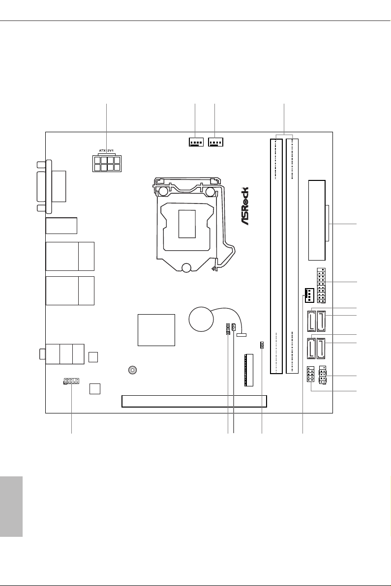
1.3 Motherboard Layout
English
6 7

No. Description
1 ATX 12V Power Connector (ATX12V1)
2 Chassis Fan / Waterpump Fan Connector (CHA_FAN1/WP)
3 CPU Fan Connector (CPU_FAN1)
4 2 x 288-pin DDR4 DIMM Slots (DDR4_A1, DDR4_B1)
5 ATX Power Connector (ATXPWR1)
6 USB 3.2 Gen1 Header (USB3_ 3_4)
7 SATA3 Connector (SATA3_1)
8 SATA3 Connector (SATA3_0)
9 SATA3 Connector (SATA3_3)
10 SATA3 Connector (SATA3_2)
11 System Panel Header (PANEL1)
12 USB 2.0 Header (USB_3_4)
13 Chassis Fan Connector (CHA_FAN2)
14 Clear CMOS Jumper (CLRMOS1)
15 Chassis Intrusion Header (CI1)
16 Chassis Speaker Header (SPEAKER1)
17 Front Panel Audio Header (HD_AUDIO1)
B360M-ITX
English
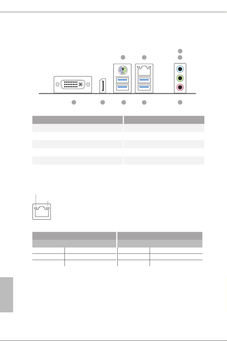
1.4 I/O Panel
9
4
6
8
1
2
3
5
7
No. Description No. Description
1 DVI-I Port (DVI1) 6 LAN RJ-45 Port*
2 DisplayPort 1.2 (DISPLAY1) 7 Microphone (Pink)
3 USB 3.2 Gen1 Ports (USB_1_2) 8 Front Speaker (Lime)
4 PS/2 Mouse/Keyboard Port 9 Line In (Light Blue)
5 USB 3.2 Gen2 Type-A Ports (USB3_1_2)
* ere are two LEDs on each LAN port. Please refer to the table below for the LAN port LED indications .
ACT/LINK LED
SPEED LED
LAN Por t
Activity / Link LED Speed LED
Status Description Status Description
O No Link O 10Mbps connection
Blinking Data Activity Orange 100Mbps connection
On Link Green 1Gbps connection
English
8 9

Chapter 2 Installation
is is a Mini-ITX form factor motherboard. Before you install the motherboard,
study the conguration of your chassis to ensure that the motherboard ts into it.
Pre-installation Precautions
Take note of the following precautions before you install motherboard components
or change any motherboard settings.
Make sure to unplug the power cord before installing or removing the motherboard
•
components. Failure to do so may cause physical injuries and damages to motherboard
components.
In order to avoid damage from static electricity to the motherboard’s components,
•
NEVER place your motherboard directly on a carpet. Also remember to use a grounded
wrist strap or touch a safety grounded object before you handle the components.
Hold components by the edges and do not touch the ICs.
•
Whenever you uninstall any components, place them on a grounded anti-static pad or
•
in the bag that comes with the components.
When placing screws to secure the motherboard to the chassis, please do not over-
•
tighten the screws! Doing so may damage the motherboard.
B360M-ITX
English
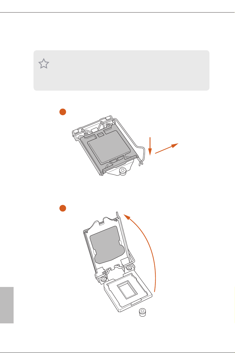
2.1 Installing the CPU
1. Before you insert the 1151-Pin CPU into the socket, please check if the PnP cap is on the
socket, if the CPU surface is unclean, or if there are any bent pins in the socket. Do not
force to in sert the CPU into the socket if above situation is found. Otherwise, the CPU
will be seriously damaged.
2. Unplug all power c ables before in stalling the CPU.
1
2
A
B
English
10 11
B360M-ITX
3
4
5
English

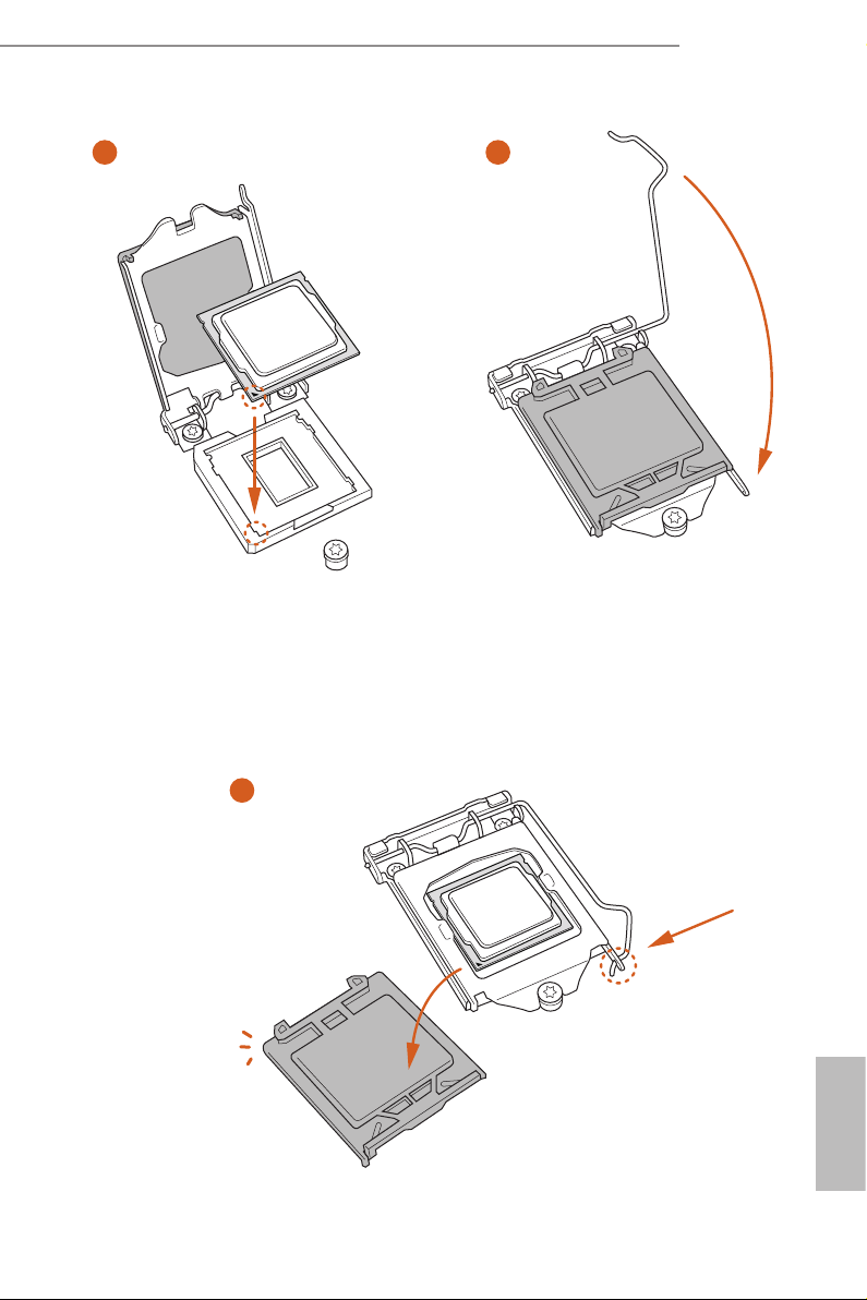
Please save and replace the cover if the processor i s removed. e cover must be placed if
you wish to return the motherboard for aer service.
English
12 13
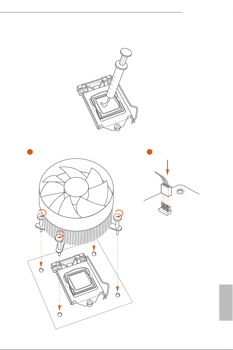
2.2 Installing the CPU Fan and Heatsink
1 2
B360M-ITX
FAN
CPU_
English
2.3 Installing Memory Modules (DIMM)
is motherboard provides two 288-pin DDR4 (Double Data Rate 4) DIMM slots,
and supports Dual Channel Memory Technology.
1. For dual channel cong uration , you always need to in stall identical (the same b rand,
speed , size and chip-type) DDR4 DIMM pairs.
2. It is unable to activate Du al Channel Memory Technology with only one memory module
installed.
3. It is not allowed to install a DDR, DDR2 or DDR3 memory module into a DDR4 sl ot;
otherwise , this motherboard and DIM M may be damaged..
e DIMM only ts in one correct orientation. It will cause permanent dam age to the
motherboard and the DIMM if you force the DIMM into the slot at incorrect orientation.
English
14 15

B360M-ITX
1
2
3
English

2.4 Expansion Slot (PCI Express Slot)
ere is 1 PCI Express slot on the motherboard.
Before installing an ex pansion card, please make sure that the power supply is switched o
or the power cord is unplug ged. Pl ease read the documentation of the expansion card and
make necessary hardware settings for the card before you start the installation.
PCIe slot:
PCIE1 (PCIe 3.0 x16 slot) is used for PCI Express x16 lane width graphics cards.
English
16 17

2.5 Jumpers Setup
e illustration shows how jumpers are setup. When the jumper cap is placed on
the pins, the jumper is “Short”. If no jumper cap is placed on the pins, the jumper is
“O pen”.
Clear CMOS Jumper
(CLRMO S1)
(see p.6, No. 14)
CLRMOS1 allows you to clear the data in CMOS. To clear and reset the system
parameters to default setup, please turn o the computer and unplug the power
cord from the power supply. Aer waiting for 15 seconds, use a jumper cap to
short the pins on CLR MOS1 for 5 seconds. However, please do not clear the
CMOS right aer you update the BIOS. If you need to clear the CMOS when you
just nish updating the BIOS, you must boot up the system rst, and then shut it
down before you do the clear-CMOS action. Please be noted that the password,
date, time, and user default prole will be cleared only if the CMOS battery is
removed. Please remember toremove the jumper cap aer clearing the CMOS.
2-pin Jumper
B360M-ITX
If you clear the CMOS, the case open may be detec ted. Please adjust the BIOS option “Clear
Status” to clear the record of previous chassis intrusion status.
English
 Loading...