

Page 1

Version 1.0
Published July 2018
Copyright©2018 ASRock INC. All rights reserved.
Copyright Notice:
No part of this documentation may be reproduced, transcribed, transmitted, or
translated in any language, in any form or by any means, except duplication of
documentation by the purchaser for backup purpose, without written consent of
ASRock Inc.
Products and corporate names appearing in this documentation may or may not
be registered trademarks or copyrights of their respective companies, and are used
only for identication or explanation and to the owners’ benet, without intent to
infringe.
Disclaimer:
Specications and information contained in this documentation are furnished for
informational use only and subject to change without notice, and should not be
constructed as a commitment by ASRock. ASRock assumes no responsibility for
any errors or omissions that may appear in this documentation.
With respect to the contents of this documentation, ASRock does not provide
warranty of any kind, either expressed or implied, including but not limited to
the implied warranties or conditions of merchantability or tness for a particular
purpose.
In no event shall ASRock, its directors, ocers, employees, or agents be liable for
any indirect, special, incidental, or consequential damages (including damages for
loss of prots, loss of business, loss of data, interruption of business and the like),
even if ASRock has been advised of the possibility of such damages arising from any
defect or error in the documentation or product.
is device complies with Part 15 of the FCC Rules. Operation is subject to the following
two conditions:
(1) this device may not cause harmful interference, and
(2) this device must accept any interference received, including interference that
may cause undesired operation.
CALIFORNIA, USA ONLY
e Lithium battery adopted on this motherboard contains Perchlorate, a toxic substance
controlled in Perchlorate Best Management Practices (BMP) regulations passed by the
California Legislature. When you discard the Lithium battery in California, USA, please
follow the related regulations in advance.
“Perchlorate Material-special handling may apply, see www.dtsc.ca.gov/hazardouswaste/
perchlorate”
ASRock Website: http://www.asrock.com
Page 2

AUSTRALIA ONLY
Our goods come with guarantees that cannot be excluded under the Australian Consumer
Law. You are entitled to a replacement or refund for a major failure and compensation for
any other reasonably foreseeable loss or damage caused by our goods. You are also entitled
to have the goods repaired or replaced if the goods fail to be of acceptable quality and the
failure does not amount to a major failure. If you require assistance please call ASRock Tel
: +886-2-28965588 ext.123 (Standard International call charges apply)
e terms HDMI™ and HDMI High-Denition Multimedia Interface, and the HDMI
logo are trademarks or registered trademarks of HDMI Licensing LLC in the United
States and other countries.
Page 3

Motherboard Layout
Intel
B250
ATXP WR 1
HDLED RE SET
PLED PWRBTN
PANEL1
1
COM1
1
B250M DASH
RoH S
CPU_FAN1
PCI E1
TPMS1
1
1
USB3_4
SPK_CI1
1
PCI E2
Fro nt USB 3. 0
CMO S
Bat ter y
DDR4 _A2 (64 b it, 288- pin modu le)
DDR4 _A1 (64 b it, 288- pin modu le)
DDR4 _B2 (64 b it, 288- pin modu le)
DDR4 _B1 (64 b it, 288- pin modu le)
ATX12V1
SATA3_2
SATA3_3
USB3_5_ 6
SATA3_4
SATA3_5
CLRMOS1
1
1
HD_AUDIO1
M2_1
CT3CT4 CT2
Top:
RJ-4 5
USB 2 .0
T: USB1
B: US B2
HDMI 1
CHA_FAN1
Top:
LINE I N
Center:
FRONT
Bottom:
MIC IN
USB 3.1 Gen1
T:USB 3_TA_1
B:U SB3_TC_ 1
PCI E3
PCI Ex pre ss 3.0
SATA3_1
CHA_FAN2
Ultr a M.2
PCIe Gen3 x4
PS2
Keybo ard
PS2
Mouse
DVI 1
VGA 1
USB 3.1 Gen1
T:USB 3
B:U SB4
CPU_FAN2
Ct1
PCI 1
1
LPT1
1
USB5_6
1
BIOS
ROM
M2_2
CT3CT4 CT2 Ct1
SATA3_0
DP1
COM2
1
BUZZ1
B250M DASH
English
1
Page 4

No. Description
1 ATX 12V Power Connector (ATX12V1)
2 Chassis Fan Connector (CHA_FAN1)
3 CPU Fan Connector (CPU_FAN1)
4 CPU Fan Connector (CPU_FAN2)
5 2 x 288-pin DDR4 DIMM Slots (DDR4_A1, DDR4_B1)
6 2 x 288-pin DDR4 DIMM Slots (DDR4_A2, DDR4_B2)
7 ATX Power Connector (ATXPWR1)
8 USB 3.1 Gen1 Header (USB3_5_6)
9 SATA3 Connector (SATA3_0)
10 SATA3 Connector (SATA3_1)
11 Chassis Fan Connector (CHA_FAN2)
12 SATA3 Connector (SATA3_2)
13 SATA3 Connector (SATA3_3)
14 SATA3 Connector (SATA3_5)
15 SATA3 Connector (SATA3_4)
16 Clear CMOS Jumper (CLRMOS1)
17 Chassis Intrusion and Speaker Header (SPK_CI1)
18 System Panel Header (PANEL1)
19 USB 2.0 Header (USB5_6)
20 USB 2.0 Header (USB3_4)
21 TPM Header (TPMS1)
22 Print Port Header (LPT1)
23 COM Port Header (COM1)
24 COM Port Header (COM2)
25 Front Panel Audio Header (HD_AUDIO1)
English
2
Page 5

I/O Panel
1 3
2
B250M DASH
4
5
14 6711
No. Description No. Description
1 PS/2 Mouse Port 8 USB 3.1 Gen1 Ports (USB3_3_4)
2 D-Sub Port 9 USB 3.1 Gen1 Type-A Port (USB3_TA_1)
3 LAN RJ-45 Port* 10 USB 3.1 Gen1 Type-C Port (USB3_TC_1)
4 Line In (Light Blue)** 11 DisplayPort 1.2
5 Front Speaker (Lime)** 12 HDMI Port
6 Microphone (Pink)** 13 DVI-D Port
7 USB 2.0 Ports (USB12) 14 PS/2 Keyboard Port
* ere are two LEDs on the LAN port. Please refer to the table below for the LAN port LED indications.
ACT/LINK L ED
SPEED LE D
LAN Por t
Activity / Link LED Speed LED
Status Description Status Description
O No Link O 10Mbps connection
Blinking Data Activity Orange 100Mbps connection
On Link Green 1Gbps connection
13
12
9
10
8
English
3
Page 6

** To congure 7.1 CH HD Audio, it i s required to use an HD front panel audio module and enable the multichannel audio feature through the audio driver.
Please set Speaker Conguration to “7.1 Speaker”in the Realtek HD Audio Manager.
Function of the Audio Por ts in 7.1-channel Con guration:
Port Function
Light Blue (Rear panel) Rear Speaker Out
Lime (Rear panel) Front Speaker Out
Pink (Rear panel) Central /Subwoofer Speaker Out
Lime (Front panel) Side Speaker Out
English
4
Page 7

Chapter 1 Introduction
ank you for purchasing ASRock B250M DASH motherboard, a reliable
motherboard produced under ASRock’s consistently stringent quality control.
It delivers excellent performance with robust design conforming to ASRock’s
commitment to quality and endurance.
Becau se the motherboard specications and the BIOS soware might be updated, the
content of this documentation will be subject to change without notice. In case any
modications of this documentation occur, the updated version will be available on
ASRock’s website w ithout f urther notice. If you require technical support relate d to
this motherboard, please vi sit our website for s pecic information about the model
you are using. You may nd the l atest VGA cards and CPU suppor t list on ASRock’s
website a s well. ASRock website ht tp://www.a srock.com.
1.1 Package Contents
ASRock B250M DASH Motherboard (Micro ATX Form Factor)
•
ASRock B250M DASH Support CD
•
2 x Serial ATA (SATA) Data Cables (Optional)
•
2 x Screws for M.2 Sockets (Optional)
•
1 x I/O Panel Shield
•
B250M DASH
English
5
Page 8

1.2 Specications
Platform
CPU
Chipset
Memory
•
•
•
•
•
•
•
•
•
•
* 7th Gen Intel® CPU supports DDR4 up to 2400; 6th Gen Intel®
CPU supports DDR4 up to 2133.
•
•
•
•
Micro ATX Form Factor
Solid Capacitor design
Supports 7th and 6th Generation Intel® CoreTM i7/i5/i3/
Pentium®/Celeron® Processors (Socket 1151)
Digi Power design
6 Power Phase design
Supports Intel® Turbo Boost 2.0 Technology
Intel® B250
Dual Channel DDR4 Memory Technology
4 x DDR4 DIMM Slots
Supports DDR4 2400/2133 non-ECC, un-buered memory*
Supports ECC UDIMM memory modules (operate in nonECC mode)
Max. capacity of system memory: 64GB
Supports Intel® Extreme Memory Prole (XMP) 2.0
15μ Gold Contact in DIMM Slots
English
6
Expansion
Slot
Graphics
2 x PCI Express 3.0 x16 Slots (PCIE1: x16 mode; PCIE3: x4
•
mode)*
* Supports NVMe SSD as boot disks
1 x PCI Express 3.0 x1 Slot (Flexible PCIe)**
•
1 x PCI Slot**
•
** If PCIE2 slot or PCI slot is occupied, the PCIe-type M.2
device on M2_1 socket will run at Gen3 x2 (16 Gb/s).
Supports AMD Quad CrossFireXTM and CrossFireX
•
Intel® HD Graphics Built-in Visuals and the VGA outputs
•
can be supported only with processors which are GPU
integrated.
Supports Intel® HD Graphics Built-in Visuals : Intel® Quick
•
Sync Video with AVC, MVC (S3D) and MPEG-2 Full
HW Encode1, Intel® InTruTM 3D, Intel® Clear Video HD
Technology, Intel® InsiderTM, Intel® HD Graphics
TM
Page 9

B250M DASH
Gen9 LP, DX11.3, DX12
•
HWAEncode/Decode: VP8, HEVC 8b, VP9, HEVC 10b (For
•
7th Gen Intel® CPU)
HWA Encode/Decode: VP8 , HEVC 8b; GPU/SWEncode/
•
Decode: VP9, HEVC 10b (For 6th Gen Intel® CPU)
Max. shared memory 1024MB
•
* e size of maximum shared memory may vary from dierent
operating systems.
Four graphics output options: D-Sub, DVI-D, HDMI and
•
DisplayPort 1.2
Supports Triple Monitor
•
Supports HDMI with max. resolution up to 4K x 2K
•
(4096x2160) @ 24Hz / (3840x2160) @ 30Hz
Supports DVI-D with max. resolution up to 1920x1200 @
•
60Hz
Supports D-Sub with max. resolution up to 1920x1200 @
•
60Hz
Supports DisplayPort 1.2 with max. resolution up to 4K x 2K
•
(4096x2304) @ 60Hz
Supports Auto Lip Sync, Deep Color (12bpc), xvYCC and
•
HBR (High Bit Rate Audio) with HDMI Port (Compliant
HDMI monitor is required)
Supports HDCP with DVI-D, HDMI and DisplayPort 1.2
•
Ports
Supports Full HD 1080p Blu-ray (BD) playback with DVI-D,
•
HDMI and DisplayPort 1.2 Ports
Audio
7.1 CH HD Audio with Content Protection (Realtek ALC892
•
Audio Codec)
* To congure 7.1 CH HD Audio, it is required to use an HD
front panel audio module and enable the multi-channel audio
feature through the audio driver.
Premium Blu-ray Audio support
•
Supports Surge Protection (ASRock Full Spike Protection)
•
ELNA Audio Caps
•
English
7
Page 10

English
LAN
Rear Panel
I/O
Storage
PCIE x1 Gigabit LAN 10/100/1000 Mb/s
•
Realtek RTL8111EPV
•
Supports Wake-On-LAN
•
Supports Lightning/ESD Protection
•
Supports LAN Cable Detection
•
Supports Energy Ecient Ethernet 802.3az
•
Supports PXE
•
Supports DASH
•
1 x PS/2 Mouse Port
•
1 x PS/2 Keyboard Port
•
1 x D-Sub Port
•
1 x DVI-D Port
•
1 x HDMI Port
•
1 x DisplayPort 1.2
•
2 x USB 2.0 Ports (Supports ESD Protection)
•
3 x USB 3.1 Gen1 Type-A Ports (Supports ESD Protection)
•
1 x USB 3.1 Gen1 Type-C Port (Supports ESD Protection)
•
1 x RJ-45 LAN Port with LED (ACT/LINK LED and SPEED
•
LED)
HD Audio Jacks: Line in / Front Speaker / Microphone
•
6 x SATA3 6.0 Gb/s Connectors, support NCQ, AHCI and
•
Hot Plug*
* If M2_1 is occupied by a SATA-type M.2 device, SATA3_0 will
be disabled.
1 x Ultra M.2 Socket (M2_1), supports M Key type
•
2230/2242/2260/2280 M.2 SATA3 6.0 Gb/s module and M.2
PCI Express module up to Gen3 x4 (32 Gb/s)**
1 x M.2 Socket (M2_2), supports M Key type
•
2230/2242/2260/2280 M.2 PCI Express module up to Gen3
x2 (16 Gb/s)**
** If PCIE2 slot or PCI slot is occupied, the PCIe-type M.2
device on M2_1 socket will run at Gen3 x2 (16 Gb/s).
** Supports NVMe SSD as boot disks
** Supports ASRock U.2 Kit
8
Page 11

Connector
B250M DASH
1 x Buzzer
•
1 x Onboard TPM 2.0
•
1 x Print Port Header
•
2 x COM Port Headers
•
1 x Chassis Intrusion and Speaker Header
•
2 x CPU Fan Connectors (1 x 4-pin, 1 x 3-pin)
•
* e CPU Fan Connector supports the CPU fan of maximum
1A (12W) fan power.
2 x Chassis Fan Connectors (4-pin) (Smart Fan Speed Con-
•
trol)
* CHA_FAN1 and CHA_FAN2 can auto detect if 3-pin or 4-pin
fan is in use.
1 x 24 pin ATX Power Connector
•
1 x 8 pin 12V Power Connector
•
1 x Front Panel Audio Connector
•
2 x USB 2.0 Headers (Support 4 USB 2.0 ports) (Supports
•
ESD Protection)
1 x USB 3.1 Gen1 Header (Supports 2 USB 3.1 Gen1 ports)
•
(Supports ESD Protection)
BIOS
Feature
Hardware
Monitor
AMI UEFI Legal BIOS with multilingual GUI support
•
ACPI 6.0 Compliant wake up events
•
SMBIOS 2.7 Support
•
CPU, GT_CPU, DRAM, PCH 1.0V, VCCIO, VCCSA, VCCST
•
Voltage Multi-adjustment
CPU/Chassis temperature sensing
•
CPU/Chassis Fan Tachometer
•
CPU/Chassis Quiet Fan (Auto adjust chassis fan speed by
•
CPU temperature)
CPU/Chassis Fan multi-speed control
•
CASE OPEN detection
•
Voltage monitoring: +12V, +5V, +3.3V, CPU Vcore, DRAM,
•
PCH 1.0V
English
9
Page 12

Microso® Windows® 10 64-bit (For 7th Gen Intel® CPU)
OS
•
Microso® Windows® 10 64-bit / 8.1 64-bit / 7 32-bit / 7 64-
•
bit (For 6th Gen Intel® CPU)
* To install Windows® 7 OS, a modied installation disk with
xHCI drivers packed into the ISO le is required. Please refer to
page 39 for more detailed instructions.
* For the updated Windows® 10 driver, please visit ASRock ’s
website for details: http://www.asrock.com
FCC, CE
Certications
* For detailed product information, please visit our website: http://ww w.asrock.com
Please realize that the re is a certain r isk involved with overclo cking, including
adjusting the setting in the BIOS, applying Untied Overclocking Technol ogy, or using
third-party overclocking tool s. Overclocking may aect your system’s stability, or
even cause dam age to the components and devices of your system. It should be done
at your own risk and expense. We are not responsible for poss ible damage caused by
overclocking.
•
ErP/EuP Ready (ErP/EuP ready power supply is required)
•
English
10
Page 13

Chapter 2 Installation
is is a Micro ATX form factor motherboard. Before you install the motherboard,
study the conguration of your chassis to ensure that the motherboard ts into it.
Pre-installation Precautions
Take note of the following precautions before you install motherboard components
or change any motherboard settings.
Make sure to unplug the power cord before installing or removing the motherboard
•
components. Failure to do so may cause physical injuries and damages to motherboard
components.
In order to avoid damage from static electricity to the motherboard’s components,
•
NEVER place your motherboard directly on a carpet. Also remember to use a grounded
wrist strap or touch a safety grounded object before you handle the components.
Hold components by the edges and do not touch the ICs.
•
Whenever you uninstall any components, place them on a grounded anti-static pad or
•
in the bag that comes with the components.
When placing screws to secure the motherboard to the chassis, please do not over-
•
tighten the screws! Doing so may damage the motherboard.
B250M DASH
11
English
Page 14
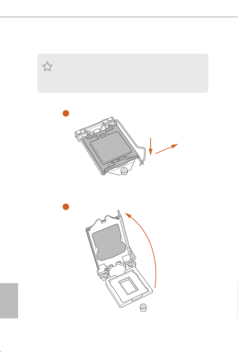
2.1 Installing the CPU
1. Before you insert the 1151-Pin CPU into the socket , please check if the PnP c ap
is on the socket, if the CPU sur face is unclean, or if th ere are any b ent pins in the
socket. Do not force to insert the CPU into the socket if above situ ation is found.
Other wise, the CPU wil l be seriously d amaged.
2. Unplug all power cables be fore installing the CPU.
1
2
A
B
English
12
Page 15

B250M DASH
3
4
5
English
13
Page 16

Please save and replace the cover if the processor i s removed. e cover must be
placed if you wish to return the motherboard for aer service.
English
14
Page 17

2.2 Installing the CPU Fan and Heatsink
1 2
B250M DASH
FAN
CPU_
English
15
Page 18

2.3 Installing Memory Modules (DIMM)
is motherboard provides four 288-pin DDR4 (Double Data Rate 4) DIMM slots,
and supports Dual Channel Memory Technology.
1. For dual channel conguration, you always need to install identica l (the same
brand, speed , size and chip-type) DDR4 DIMM pairs.
2. It is unable to activate Dual Channel Memor y Technology with only one or three
memor y module installed.
3. It is not allowed to install a DDR, DDR2 or DDR3 memory module into a DDR4
slot; otherwise, this motherboard and DIMM may be damaged.
Dual Channel Memory Conguration
Priority DDR4_ A1 DDR4_A2 DDR4_B1 DDR4_B2
1 Populated Populated
2 Populated Populated
3 Populated Populated Populated Populated
e DIMM only ts in one correct orie ntation. It will cause permanent dam age to
the mothe rboard and the DIMM if you force the DIMM into the slot at incor rect
orientation .
English
16
Page 19

B250M DASH
1
2
3
English
17
Page 20

2.4 Expansion Slots (PCI and PCI Express Slots)
ere is 1 PCI slot and 3 PCI Express slots on the motherboard.
Before installing an ex pansion card, please make sure that the power supply is
switched o or the power cord is unplugged. Plea se read the documentation of the
expan sion card and mak e necessary hardware settings for the card before you start
the installation.
PCI slot:
e PCI1 slot is used to install expansion cards that have 32-bit PCI interface.
PCIe slots:
PCIE1 (PCIe 3.0 x16 slot) is used for PCI Express x16 lane width graphics cards.
PCIE2 (PCIe 3.0 x1 slot) is used for PCI Express x1 lane width cards.
PCIE3 (PCIe 3.0 x16 slot) is used for PCI Express x4 lane width graphics cards.
* If PCIE2 slot or PCI slot is occupied, the PCIe-type M.2 device on M2_1 socket
will run at Gen3 x2 (16 Gb/s).
PCIe Slot Congurations
PCIE1 PCIE3
Single Graphics Card x16 N/A
English
18
Two Graphics Cards in
CrossFireXTM Mode
For a better ther mal environment, ple ase connect a ch assi s fan to the motherboard’s
chassis fan connector (CHA_ FAN1 or CHA_ FAN2) when using multiple graphics
cards.
x16 x4
Page 21

2.5 Jumpers Setup
e illustration shows how jumpers are setup. When the jumper cap is placed on
the pins, the jumper is “Short”. If no jumper cap is placed on the pins, the jumper
is “Open”. e illustration shows a 3-pin jumper whose pin1 and pin2 are “Short”
when a jumper cap is placed on these 2 pins.
Clear CMOS Jumper
(CLRMOS1)
(see p.1, No. 16)
CLRMOS1 allows you to clear the data in CMOS. To clear and reset the system
parameters to default setup, please turn o the computer and unplug the power
cord from the power supply. Aer waiting for 15 seconds, use a jumper cap to
short pin2 and pin3 on CLRMOS1 for 5 seconds. However, please do not clear the
CMOS right aer you update the BIOS. If you need to clear the CMOS when you
just nish updating the BIOS, you must boot up the system rst, and then shut it
down before you do the clear-CMOS action. Please be noted that the password,
date, time, and user default prole will be cleared only if the CMOS battery is
removed.
Clear CMOSDefault
B250M DASH
If you clear the CMOS, the case open may be detec ted. Please adjust the BIOS option
“Clear Status” to clear the record of previou s chassis intrusion status.
English
19
Page 22

2.6 Onboard Headers and Connectors
Onboard headers and connectors are NOT jumpers. Do NOT place jumper caps over
these header s and connectors. Placing jumper caps over the headers and connectors
will cause permanent damage to the motherboard.
System Panel Header
(9-pin PANEL1)
(see p.1, No. 18)
PWRBTN (Power Switch):
Connec t to the power switch on the chassi s front panel. You may congure the way to
turn o your system using the power switch.
RESET (Reset Switch):
Connec t to the reset switch on the chassi s front panel. P ress the reset sw itch to restart
the computer if the compute r freezes and fails to perform a normal restart.
PLED (Syste m Power LED):
Connec t to the power status indicator on the chassis front panel. e LED i s on when
the system is ope rating. e LED keeps blinking when the system i s in S1/S3 sleep
state. e LED is o when the system is in S4 sleep state or powered o (S5).
HDLED (Ha rd Drive Activity LED):
Connec t to the hard drive ac tivity LED on the chassis front panel. e LED is on
when the hard drive i s reading or writing data.
e front panel de sign may dier by chassis. A front pane l module mainly consists
of power switch , reset switch, power LED, hard dr ive activity LED, speak er and etc.
When connecting your chassis front panel module to this head er, make sure the wire
assig nments and the pin assig nments are matched correctly.
1
PLE D+
PLE D-
HDL ED-
HDL ED+
PWR BTN #
GND
RES ET#
GND
GND
Connect the power
switch, reset switch and
system status indicator on
the chassis to this header
according to the pin
assignments below. Note
the positive and negative
pins before connecting
the cables.
English
20
Page 23

B250M DASH
SPE AKE R
Chassis Intrusion and
Speaker Header
(7-pin SPK_CI1)
(see p.1, No. 17)
Serial ATA3 Connectors
(SATA3_0:
see p.1, No. 9)
(SATA3_1:
see p.1, No. 10)
(SATA3_2:
see p.1, No. 12)
(SATA3_3:
see p.1, No. 13)
(SATA3_4:
see p.1, No. 15)
(SATA3_5:
see p.1, No. 14)
USB 2.0 Headers
(9-pin USB3_4)
(see p.1, No. 20)
(9-pin USB5_6)
(see p.1, No. 19)
DUM MY
+5V
1
SIG NAL
SATA3_2
SATA3_4
USB _PW R
1
USB _PW R
DUM MY
P-
P-
GND
DUM MY
P+
P+
GND
GND
DUM MY
Please connect the
chassis intrusion and the
chassis speaker to this
header.
ese six SATA3
connectors support SATA
data cables for internal
SATA3_0
storage devices with up to
6.0 Gb/s data transfer rate.
SATA3_1
* If M2_1 is occupied by
a SATA-type M.2 device,
SATA3_0 will be disabled.
SATA3_3
SATA3_5
ere are two headers
on this motherboard.
Each USB 2.0 header can
support two ports.
USB 3.1 Gen1 Header
(19-pin USB3_5_6)
(see p.1, No. 8)
Vbus
IntA _PA_S SRX-
IntA _PA_S SRX+
GND
IntA _PA_S STX-
IntA _PA_S STX+
GND
IntA _PA_D -
IntA _PA_D +
VbusVbus
IntA _PB_ SSRX -
IntA _PB_ SSRX +
GND
IntA _PB_ SSTX -
IntA _PB_ SSTX +
GND
IntA _PB_ D-
IntA _PB_ D+
Dumm y
1
ere is one header on
this motherboard. Each
USB 3.1 Gen1 header can
support two ports.
English
21
Page 24

Front Panel Audio Header
GND
FAN_V OLTAGE _CO NTRO L
FAN_S PEE D
FAN_S PEE D_CO NTR OL
GND
FAN_V OLTAGE _CO NTR OL
FAN_S PEE D
FAN_S PEE D_C ONTR OL
GND
FAN_ VOLTAG E
FAN_ SPE ED
(9-pin HD_AUDIO1)
(see p.1, No. 25)
1. High Denition Audio supports Jack Sensing, but the panel wire on the chassis
must support HDA to function correctly. Please follow the instructions in our
manual and chassis manual to install your system.
2. If you use an AC’97 audio panel, please install it to the front panel audio heade r by
the steps below:
A. Connect Mic_IN (MIC) to MIC2_ L.
B. Conne ct Audio_R (RIN) to OUT2_R and Audio_ L (LIN) to OUT2_ L.
C. Connect Ground (GND) to Ground (GND).
D. MIC_ RET and OUT_RET are for the HD audio panel only. You don’t need to
connec t them for the AC’97 audio panel.
E. To activate the front mic, go to the “FrontMic” Tab in the Realtek Control panel
and adju st “Recording Volume”.
1
GND
PRE SEN CE#
MIC 2_R
MIC 2_L
MIC _RE T
J_S ENS E
OUT 2_R
OUT _RE T
OUT 2_L
is header is for
connecting audio devices
to the front audio panel.
English
22
Chassis Fan Connectors
(4-pin CHA_FAN1)
(see p.1, No. 2)
(4-pin CHA_FAN2)
(see p.1, No. 11)
CPU Fan Connectors
(4-pin CPU_FAN1)
(see p.1, No. 3)
(3-pin CPU_FAN2)
(see p.1, No. 4)
FAN _SP EE D_ CON TR OL
FAN _SP EE D
FAN _V OL TA GE
GND
Please connect fan cables
4
3
to the fan connector and
2
match the black wire to
1
the ground pin.
is motherboard provides two 4-Pin CPU fan
(Quiet Fan) connectors.
If you plan to connect a
3-Pin CPU fan, please
connect it to Pin 1-3.
Page 25

B250M DASH
1
ATX Power Connector
(24-pin ATXPWR1)
(see p.1, No. 7)
ATX 12V Power
Connector
(8-pin ATX12V1)
(see p.1, No. 1)
Serial Port Headers
(9-pin COM1)
(see p.1, No. 23)
(9-pin COM2)
(see p.1, No. 24)
TPM Header
(17-pin TPMS1)
(see p.1, No. 21)
12
24
is motherboard provides a 24-pin ATX power
connector. To use a 20-pin
ATX power supply, please
plug it along Pin 1 and Pin
1
13
8
5
13.
is motherboard provides an 8-pin ATX 12V
power connector. To use a
4-pin ATX power supply,
please plug it along Pin 1
and Pin 5.
ese headers support
serial port modules.
is connector supports Trusted
GN D
LAD 0
+3V S B
D
GN
GN D
SER IRQ #
S_P WRD WN #
PC ICL K
LAD 3
+3 V
PC IRS T #
FRA M E
Platform Module (TPM) system,
1
which can securely store keys,
digital certicates, passwords,
GN D
LAD 1
LAD 2
and data. A TPM system also
helps enhance network security,
SMB _CL K_M AIN
SMB _DA TA_ MAI N
protects digital identities, and
ensures platform integrity.
Print Port Header
(25-pin LPT1)
(see p.1, No. 22)
1
AFD #
STB #
ERR OR#
PIN I T#
SPD 1
SPD 0
SLI N #
SPD 2
SPD 3
SPD 4
SPD 5
SPD 6
GND
SPD 7
ACK #
BUS Y
is is an interface
for print port cable
that allows convenient
connection of printer
PE
SLC T
devices.
English
23
Page 26

2.7 M.2_SSD (NGFF) Module Installation Guide
5
The M.2, also known as the Next Generation Form Factor (NGFF), is a small size and
versatile card edge connector that aims to replace mPCIe and mSATA. The Ultra M.2
Socket (M2_1) supports type 2230/2242/2260/2280 M.2 SATA3 6.0 Gb/s module and
M.2 PCI Express module up to Gen3 x4 (32 Gb/s). e M.2 Socket (M2_2) supports type
2230/2242/2260/2280 M.2 PCI Express module up to Gen3 x2 (16 Gb/s).
* Please be noted that if M2_1 is occupied by a SATA-type M.2 device, SATA3_0 will be
disabled.
* If PCIE2 slot or PCI slot is occupied, the PCIe-type M.2 device on M2_1 socket will run
at Gen3 x2 (16 Gb/s).
Installing the M.2_SSD (NGFF) Module
Step 1
Prepare a M.2_SSD (NGFF) module
and the screw.
English
24
4
3
Step 2
Depending on the PCB type and
length of your M.2_SSD (NGFF)
module, nd the corresponding nut
2
1
location to be used.
No. 1 2 3 4
Nut Location A B C D
PCB Length 3cm 4.2cm 6cm 8cm
Module Type Type2230 Type 2242 Type2260 Type 2280
Page 27

B250M DASH
Step 3
Move the stando based on the
A
BCD
A
BCD
module type and length.
e stando is placed at the nut
location D by default. Skip Step 3 and
4 and go straight to Step 5 if you are
going to use the default nut.
Otherwise, release the stando by
hand.
Step 4
Peel o the yellow protective lm on
the nut to be used. Hand tighten the
stando into the desired nut location
on the motherboard.
Step 5
Gently insert the M.2 (NGFF) SSD
module into the M.2 slot. Please
be aware that the M.2 (NGFF) SSD
module only ts in one orientation.
Step 6
Tighten the screw with a screwdriver
NUT1NUT2D
to secure the module into place.
Please do not overtighten the screw as
this might damage the module.
English
25
Page 28

M.2_SSD (NGFF) Module Support List (M2_1)
Vendor Size Interface Length P/N
ADATA 128GB SATA3 2280 AXNS381E-128GM-B
ADATA 256GB SATA3 2280 AXNS381E-256GM-B
ADATA 32GB SATA3 2230 AXNS330E-32GM-B
Crucial 120GB SATA3 2280 CT120M500SSD4
Crucial 240GB SATA3 2280 CT240M500SSD4
Intel 80GB SATA3 2280 Intel SSDSCKGW080A401/80G
Intel 256GB PCIe3 x4 2280 SSDPEKKF256G7
Intel 512GB PCIe3 x4 2280 SSDPEKKF512G7
Kingston 120GB SATA3 2280 SM2280S3
Kingston 480GB PCIe2 x4 2280 SH2280S3/480G
OCZ 512GB PCIe3 x4 2280 RVD400 -M2280-512G (NVME)
Plextor 128GB PCIe3 x4 2280 PX-128M8PeG
Plextor 1TB PCIe3 x4 2280 PX-1TM8PeG
Plextor 256GB PCIe3 x4 2280 PX-256M8PeG
Plextor 256GB PCIe 2280 PX-G256M6e
Plextor 512GB PCIe3 x4 2280 PX-512M8PeG
Plextor 512GB PCIe 2280 PX-G512M6e
Samsung 256GB PCIe3 x4 2280 SM951 (MZHPV256HDGL)
Samsung 256GB PCIe3 x4 2280 SM951 (NVME)
Samsung 512GB PCIe3 x4 2280 SM951 (MZHPV512HDGL)
Samsung 512GB PCIe3 x4 2280 SM951 (NVME)
Samsung 512GB PCIe x4 2280 XP941-512G (MZHPU512HCGL)
SanDisk 128GB PCIe 2260 SD6PP4M-128G
SanDisk 256GB PCIe 2260 SD6PP4M-256G
Team 128GB SATA3 2242 TM4PS4128GMC105
Team 128GB SATA3 2280 TM8PS4128GMC105
Team 256GB SATA3 2280 TM8PS4256GMC105
Team 256GB SATA3 2242 TM4PS4256GMC105
Transcend 256GB SATA3 2242 TS256GMTS400
Transcend 512GB SATA3 2260 TS512GMTS600
Transcend 512GB SATA3 2280 TS512GMTS800
V-Color 120GB SATA3 2280 VLM100-120G-2280B-RD
V-Color 240GB SATA3 2280 VLM100-240G-2280B-RD
V-Color 240GB SATA3 2280 VSM100-240G-2280
English
26
For the latest updates of M.2_SSD (NFGG) module support list, please visit our website
for details: http://www.asrock.com
Page 29

B250M DASH
M.2_SSD (NGFF) Module Support List (M2_2)
Vendor Size Interface Length P/N
Plextor 256GB PCIe 2280 PX-G256M6e
Plextor 512GB PCIe 2280 PX-G512M6e
SanDisk 128GB PCIe 2260 SD6PP4M-128G
SanDisk 256GB PCIe 2260 SD6PP4M-256G
For the latest updates of M.2_SSD (NFGG) module support list, please visit our website
for details: http://www.asrock.com
27
English
Page 30

1 Introducción
Gracias por comprar la placa base ASRock B250M DASH, una placa base able
fabricada según el rigurosísimo control de calidad de ASRock. Ofrece un rendimiento
excelente con un diseño resistente de acuerdo con el compromiso de calidad y
resistencia de ASRock.
Ya que las especicaciones de la placa base y el soware del BIOS podrán ser actualizados, el contenido que aparece en esta documentación estará sujeto a modicaciones sin
previo aviso. Si esta documentación sufre alguna modicación, la versión actualizada
estará disponible en el sitio web de ASRock sin previo aviso. Si necesita asistencia técnica
relacionada con esta placa base, visite nuestro sitio web para obtener información
especíca sobre el modelo que esté utilizando. Podrá encontrar las últimas tarjetas VGA,
así como la lista de compatibilidad de la CPU, en el sitio web de ASRock. Sitio web de
ASRock http://www.asrock.com.
1.1 Contenido del paquete
Placa base ASRock B250M DASH (Factor de forma Micro ATX)
•
CD de soporte de ASRock B250M DASH
•
2 x cables de datos Serie ATA (SATA) (Opcional)
•
2 x tornillos para sockets M.2 (Opcional)
•
1 x escudo panel I/O
•
Español
28
Page 31

1.2 Especicaciones
Factor de forma Micro ATX
Plataforma
CPU
•
Diseño de condensador sólido
•
Admite la familia de procesadores Intel® CoreTM i7/i5/i3/Pentium®/
•
Celeron® (zócalo 1151) de la 7ª y 6ª generación
Digi Power design
•
Diseño de 6 fases de alimentación
•
Admite la tecnología Intel® Turbo Boost 2.0
•
B250M DASH
Conjunto de
chips
Memoria
Expansión
Ranura
Grácos
Intel® B250
•
Tecnología de memoria DDR4 de doble canal
•
4 x Ranuras DIMM DDR4
•
Admite memoria DDR4 2400/2133 no ECC, sin búfer*
•
* CPU Intel® de 7a generación compatible con DDR4 de hasta 2400;
CPU Intel® de 6a generación compatible con DDR4 de hasta 2133.
Admite módulos de memoria UDIMM ECC (funcionamiento en
•
modo no ECC)
Capacidad máxima de memoria del sistema: 64GB
•
Admite Perl de memoria extremo de Intel® (XMP) 2.0
•
Contacto 15μ Gold en ranuras DIMM
•
2 x ranuras PCI Express 3.0 x16 (PCIE1:modo x16; PCIE3:modo
•
x4)*
* Admite unidad de estado sólido de NVMe como disco de arranque
1 x ranura PCI Express 3.0 x1 (Flexible PCIe)**
•
1 x ranura PCI**
•
** Si la ranura PCIE2 o la ranura PCI está ocupada, el dispositivo M.2
de tipo PCIe en el zócalo M2_1 funcionará a Gen3 x2 (16 Gb/s).
Compatible con AMD Quad CrossFireXTM y CrossFireX
•
Intel® HD Graphics Built-in Visuals y las salidas de VGA son
•
compatibles únicamente con procesadores con GPU integrado.
Admite Intel® HD Graphics Built-in Visuals: Intel® Quick Sync
•
Video con AVC, MVC (S3D) y MPEG-2 Full HW Encode1, Intel®
InTruTM 3D, Intel® Clear Video HD Technology, Intel® InsiderTM,
Intel® HD Graphics
Gen9 LP, DX11.3, DX12
•
TM
Español
29
Page 32

Español
Audio
Codicación y descodicación HWA: VP8, HEVC 8b, VP9,
•
HEVC 10b (para CPU Intel® de la 7ª generación)
Codicación y descodicación HWA: VP8, HEVC 8b;
•
codicación y descodicación GPU/SW: VP9, HEVC 10b (para
CPU Intel® de la 6ª generación)
Memoria máxima compartida de 1.024MB
•
* El tamaño de memoria compartida máxima puede variar en función
de los sistemas operativos.
Cuatro opciones de salida de grácos: D-Sub, DVI-D, HDMI y
•
DisplayPort 1.2
Compatible con tres monitores
•
Admite la tecnología HDMI con una resolución máxima de
•
4K x 2K (4096x2160) a 24Hz / (3840x2160) a 30Hz
Compatible con DVI-D con máxima resolución hasta
•
1920x1200 @ 60Hz
Admite D-Sub con una resolución máxima de 1920x1200 a 60 Hz
•
Compatible con DisplayPort 1.2 con una resolución máxima de
•
4K x 2K (4096x2304) a 60 Hz
Admite Sincronización automática entre audio y vídeo, color
•
profundo (12 bpc), xvYCC y HBR (audio de alta tasa de bits) con
puerto HDMI (se necesita un monitor compatible con HDMI)
Compatible con función HDCP con puertos DVI-D, HDMI y
•
DisplayPort 1.2
Compatible con reproducción Blu-ray (BD) Full HD de 1080p
•
con puertos DVI-D, HDMI y DisplayPort 1.2
7.1 Audio CH HD con Protección de contenido (Realtek ALC892
•
Audio Codec)
* Para congurar 7.1 Audio CH HD, deberá utilizar un módulo del
panel frontal de audio HD y habilitar la característica de audio
multicanal a través del controlador de audio.
Compatible con audio Blu-ray Premium
•
Compatible con protección por sobretensión (protección ASRock
•
Full Spike)
Tapas de audio ELNA
•
30
Page 33

LAN
E/S en panel
posterior
Almacenamiento
B250M DASH
PCIE x1 Gigabit LAN 10/100/1000 Mb/s
•
Realtek RTL8111EPV
•
Admite la función Reactivación de LAN
•
Admite protección contra rayos y ESD (protección total contra
•
picos ASRock)
Admite detección de conexión de cable LAN
•
Admite Ethernet 802.3az de eciencia energética
•
Admite PXE
•
Admite DASH
•
1 x puerto de ratón PS/2
•
1 x puerto de teclado PS/2
•
1 x puerto D-Sub
•
1 x puerto DVI-D
•
1 x puerto HDMI
•
1 x DisplayPort 1.2
•
2 x puertos USB 2.0 (compatible con protección contra
•
electricidad estática)
3 x puertos USB 3.1 Gen1 de tipo A (compatible con protección
•
contra electricidad estática)
1 x puerto USB 3.1 Gen1 de tipo C (compatible con protección
•
contra electricidad estática)
1 x puerto LAN RJ-45 con LED (LED DE ACTIVIDAD/ENLACE
•
y LED DE VELOCIDAD)
Conector de audio HD: Entrada de línea / Altavoz frontal /
•
Micrófono
6 x conectores SATA3 de 6,0 Gb/s, compatibles con las funciones
•
NCQ, AHCI y Conexión en caliente*
* Si M2_1 se ocupa con un dispositivo M.2 de tipo SATA, SATA3_0
se deshabilitará.
1 x Zócalo Ultra M.2 (M2_1) que admite el módulo SATA3 6,0
•
Gb/s M.2 de tipo 2230/2242/2260/2280 y el módulo PCI Express
M.2 hasta Gen3 x4 (32 Gb/s)**
1 x socket M.2 (M2_2), compatible con el módulo express M.2
•
PCI de tipo 2230/2242/2260/2280 hasta Gen3 x2 (16 Gb/s)**
** Si la ranura PCIE2 o la ranura PCI está ocupada, el dispositivo M.2
de tipo PCIe en el zócalo M2_1 funcionará a Gen3 x2 (16 Gb/s).
** Admite unidad de estado sólido de NVMe como disco de arranque
** Admite el kit U.2 de ASRock
Español
31
Page 34

Español
Conector
Función del
BIOS
Monitor de
hardware
1 x Zumbador
•
1 x TPM 2.0
•
1 x Base de conexiones de puerto de impresión
•
2 x Base de conexiones de puerto COM
•
1 x Cabezal de intrusión de chasis y de altavoces
•
2 x Conectores para ventilador de la CPU (1 x 4 contactos, 1 x 3
•
contactos)
* El conector para ventilador de la CPU admite ventilador de la CPU
con una potencia de ventilador de 1 A (12 W) máxima.
2 x Conectores (4 contactos) para el ventilador del chasis (control
•
de velocidad de ventilador inteligente)
* CHA_FAN1 y CHA_FAN2 se pueden detectar automáticamente si
se usa el ventilador de 3 o 4 pines.
1 x Conector de alimentación ATX de 24 contactos
•
1 x Conector de alimentación de 12V de 8 pines
•
1 x Conector de audio en el panel frontal
•
2 x Bases de conexiones USB 2.0 (admite 4 puertos USB 2.0).
•
Admite protección contra ESD
1 x Base de conexiones USB 3.1 Gen1 (admite 2 puertos USB 3.1
•
Gen1). Admite protección contra ESD
BIOS legal UEFI AMI compatible con interfaz gráca de usuario
•
multilingüe
Eventos de reactivación compatibles con ACPI 6.0
•
Admite SMBIOS 2.7
•
Multi-ajuste de voltaje de CPU, GT_CPU, DRAM, PCH 1,0V,
•
VCCIO, VCCSA y VCCST
Método de sensor de temperatura de la CPU/Chasis
•
Tacómetro del ventilador de la CPU/Chasis
•
CPU/Chasis Ventilador silencioso (Ajuste automático de veloci-
•
dad del ventilador del chasis por temperatura de la CPU)
Control multivelocidad del ventilador de la CPU/Chasis
•
Detección de CARCASA ABIERTA
•
Supervisión del voltaje: +12V, +5V, +3,3V, CPU Vcore, DRAM,
•
PCH 1,0V
32
Page 35

Microso® Windows® 10 64 bits (para CPU Intel® de la 7a)
SO
•
Microso® Windows® 10 64 bits / 8.1 64 bits / 7 32 bits / 7 64 bits
•
(para CPU Intel® de la 6a generación)
* Para instalar el sistema operativo Windows® 7, se necesita un disco
de instalación modicado con los controladores xHCI empaquetados
en el archivo ISO. Consulte la página 39 para obtener información
más detallada.
* Para obtener el controlador actualizado para Windows® 10, visite el
sitio Web desde ASRock para obtener detalles:
http://www.asrock.com
FCC, CE
Certicaciones
•
Compatible con ErP/EuP (requiere toma de alimentación
•
compatible con ErP/EuP)
* Para obtener información detallada del producto, visite nuestro sitio Web: http://www.asrock.com
Tenga en cuenta que hay un cierto riesgo implícito en las operaciones de aumento de la
velocidad del reloj, incluido el ajuste del BIOS, aplicando la tecnología de aumento de
velocidad liberada o utilizando las herramientas de aumento de velocidad de otros fabricantes. El aumento de la velocidad puede afectar a la estabilidad del sistema e, incluso,
dañar los componentes y dispositivos del sistema. Esta operación se debe realizar bajo su
propia responsabilidad y usted debe asumir los costos. No asumimos ninguna responsabilidad por los posibles daños causados por el aumento de la velocidad del reloj.
B250M DASH
33
Español
Page 36

Español
1.3 Instalación de los puentes
La instalación muestra cómo deben instalarse los puentes. Cuando la tapa de puente se
coloca en los contactos, el puente queda “Corto”. Si no coloca la tapa de puente en los
contactos, el puente queda “Abierto”. La ilustración muestra un puente de 3 contactos
cuyo contacto 1 y contacto 2 son “Cortos” cuando se coloca una tapa de puente en estos
2 contactos.
Puente de borrado de CMOS
(CLRMOS1)
(consulte la pág. 1, N.º 16)
CLRMOS1 le permite borrar los datos del CMOS. Para borrar y restablecer los parámetros
del sistema a los valores predeterminados de instalación, apague el ordenador y desenchufe
el cable de alimentación de la toma de alimentación. Después de esperar 15 segundos,
utilice un tapa de puente para acortar el contacto2 y el contacto3 en el CLRMOS1 durante
5 segundos. Sin embargo, no borre el CMOS justo después de que haya actualizado la
BIOS. Si necesita borrar el CMOS cuando acabe de actualizar la BIOS, deberá arrancar
el sistema primero y, a continuación, deberá apagarlo antes de que realice el borrado
del CMOS. Tenga en cuenta que la contraseña, la fecha, la hora y el perl de usuario
predeterminado serán eliminados únicamente si se retira la pila del CMOS.
Borrado de CMOSPredeterminado
34
Si borra el CMOS, podrá detectarse la cubierta abierta. Ajuste la opción del BIOS “Clear
Status” (Borrar estado) para borrar el registro del estado de intrusión anterior del chasis.
Page 37

1.4 Conectores y cabezales incorporados
Los cabezales y conectores incorporados NO son puentes. NO coloque tapas de puente sobre estos cabezales y conectores. Si coloca tapas de puente sobre los cabezales y conectores
dañará de forma permanente la placa base.
B250M DASH
Cabezal del panel del
sistema
(PANEL1 de 9 pines)
(consulte la pág.1, n.º 18)
PWRBTN (Interruptor de alimentación):
Conéctelo al interruptor de alimentación del panel frontal del chasis. Deberá congurar
la forma en la que su sistema se apagará mediante el interruptor de alimentación.
RESET (Interruptor de reseteo):
Conéctelo al interruptor de reseteo del panel frontal del chasis. Pulse el interruptor de
reseteo para resetear el ordenador si éste está bloqueado y no se puede reiniciar de forma
normal.
PLED (Indicador LED de la alimentación del sistema):
Conéctelo al indicador de estado de la alimentación del panel frontal del chasis. El indicador LED permanece encendido cuando el sistema está funcionando. El indicador LED
parpadea cuando el sistema se encuentra en estado de suspensión S1/S3. El indicador
LED se apaga cuando el sistema se encuentra en estado de suspensión S4 o está apagado
(S5).
HDLED (Indicador LED de actividad en el disco duro):
Conéctelo al indicador LED de actividad en el disco duro del panel frontal del chasis. El
indicador LED permanece encendido cuando el disco duro está leyendo o escribiendo
datos.
El diseño del panel frontal puede ser diferente dependiendo del chasis. Un módulo de
panel frontal consta principalmente de: interruptor de alimentación, interruptor de
reseteo, indicador LED de alimentación, indicador LED de actividad en el disco duro,
altavoz, etc. Cuando conecte su módulo del panel frontal del chasis a este cabezal, asegúrese de que las asignaciones de los cables y los pines coinciden correctamente.
1
PLE D+
PLE D-
HDL ED-
HDL ED+
PWR BTN #
GND
RES ET#
GND
GND
Conecte el interruptor de
alimentación, restablezca el
interruptor y el indicador
del estado del sistema del
chasis a los valores de este
cabezal, según los valores
asignados a los pines como
se indica a continuación.
Cerciórese de cuáles son
los pines positivos y los
negativos antes de conectar
los cables.
Español
35
Page 38

Cabezal de intrusión de
SPE AKE R
chasis y de altavoces
(SPK_CI1 de 7 pines)
(consulte la pág.1, nº 17)
DUM MY
+5V
1
SIG NAL
DUM MY
GND
DUM MY
Conecte la intrusión de
chasis y el altavoz del
chasis a este cabezal.
Español
Conectores Serie ATA3
(SATA3_0:
consulte la pág.1, n.º 9)
(SATA3_1:
consulte la pág.1, n.º 10)
(SATA3_2:
consulte la pág.1, n.º 12)
(SATA3_3:
consulte la pág.1, n.º 13)
(SATA3_4:
consulte la pág.1, n.º 15)
(SATA3_5:
consulte la pág.1, n.º 14)
Cabezales USB 2.0
(USB3_4 de 9 pines)
(consulte la pág.1, nº 20)
(USB5_6 de 9 pines)
(consulte la pág.1, nº 19)
Cabezal USB 3.1 Gen1
(USB3_5_6 de 19 pines)
(consulte la pág.1, nº 8)
SATA3_2
SATA3_4
USB _PW R
1
USB _PW R
IntA _PA_S SRX-
IntA _PA_S SRX+
IntA _PA_S STX-
IntA _PA_S STX+
IntA _PA_D -
IntA _PA_D +
Vbus
GND
GND
Estos seis conectores
SATA3 son compatibles
con cables de datos SATA
SATA3_0
para dispositivos de
almacenamiento interno
SATA3_1
con una velocidad de
transferencia de datos de
hasta 6,0 Gb/s.
* Si M2_1 se ocupa con
un dispositivo M.2 de
SATA3_3
tipo SATA, SATA3_0 se
deshabilitará.
SATA3_5
P-
P+
GND
DUM MY
GND
P+
P-
VbusVbus
IntA _PB_ SSRX -
IntA _PB_ SSRX +
GND
IntA _PB_ SSTX -
IntA _PB_ SSTX +
GND
IntA _PB_ D-
IntA _PB_ D+
Dumm y
1
Hay dos bases de
conexiones en esta placa
base. Cada cabezal USB 2.0
admite dos puertos.
Esta placa base tiene otra
base de conexiones. Cada
cabezal USB 3.1 Gen1
admite dos puertos.
36
Page 39

B250M DASH
GND
FAN_V OLTAGE _CO NTRO L
FAN_S PEE D
FAN_S PEE D_CO NTR OL
GND
FAN_ VOLTAG E
FAN_ SPE ED
GND
FAN_V OLTAGE _CO NTR OL
FAN_S PEE D
FAN_S PEE D_C ONTR OL
Cabezal de audio del panel
frontal
(HD_AUDIO1 de 9 pines)
(consulte la pág.1, nº 25)
1. El Audio de Alta Denición (HDA, en inglés) es compatible con el método de sensor de
conectores, sin embargo, el cable del panel del chasis deberá ser compatible con HDA
para que pueda funcionar correctamente. Siga las instrucciones que se indican en
nuestro manual y en el manual del chasis para instalar su sistema.
2. Si utiliza un panel de audio AC’97, colóquelo en el cabezal de audio del panel frontal
siguiendo los pasos que se describen a continuación:
A. Conecte Mic_IN (MIC) a MIC2_L.
B. Conecte Audio_R (RIN) a OUT2_R y Audio_L (LIN) a OUT2_L.
C. Conecte Ground (Conexión a tierra) (GND) a Ground (GND).
D. MIC_RET y OUT_RET se utilizan únicamente con el panel de audio HD. No es
necesario que los conecte en el panel de audio AC’97.
E. Para activar el micrófono frontal, vaya a la cha “micrófono frontal” (FrontMic) en
el panel de control de Realtek y ajuste el “Volumen de grabación” (Recording Volume).
Conectores para el ventilador del chasis
(CHA_FAN1 de 4 pines)
(consulte la pág.1, n.º 2)
(CHA_FAN2 de 4 pines)
(consulte la pág.1, n.º 11)
Conectores del ventilador
de la CPU
(CPU_FAN1 de 4 pines)
(consulte la pág.1, n.º 3)
(CPU_FAN2 de 3 pines)
(consulte la pág.1, N.º 4)
GND
PRE SEN CE#
MIC _RE T
1
J_S ENS E
OUT 2_R
MIC 2_R
MIC 2_L
FAN _SP EE D_ CON TR OL
FAN _SP EE D
FAN _V OL TA GE
GND
OUT _RE T
OUT 2_L
Este cabezal se utiliza para
conectar dispositivos de
audio al panel de audio
frontal.
Conecte el cable del
4
3
ventilador al conector del
2
ventilador y haga coincidir
1
el cable negro con el pin de
conexión a tierra.
Esta placa base contiene
un conector de ventilador
(ventilador silencioso) de
CPU de 4 pines. Si tiene
pensando conectar un ventilador de CPU de 3 pines,
conéctelo al Pin 1-3.
Español
37
Page 40

Conector de alimentación
1
ATX
(ATXPWR1 de 24 pines)
(consulte la pág.1, nº 7)
12
24
Esta placa base contiene
un conector de alimentación ATX de 24 pines.
Para utilizar una toma
de alimentación ATX de
1
13
20 pines, conéctela en los
Pines del 1 al 13.
Español
Conector de alimentación
ATX de 12V
(ATX12V1 de 8 pines)
(consulte la pág.1, nº 1)
Cabezal de puerto serie
(COM1 de 9 pines)
(consulte la pág.1, nº 23)
(COM2 de 9 pines)
(consulte la pág.1, nº 24)
Cabezal TPM
(TPMS1 de 17 pines)
(consulte la pág.1, nº 21)
8
5
Esta placa base contiene
un conector de alimentación ATX de 12V y 8
pines. Para utilizar una
toma de alimentación ATX
de 4 pines, conéctela en los
Pines del 1 al 5.
Este cabezal COM admite
un módulo de puerto serie.
Este conector es compatible con el
sistema Módulo de Plataforma
GN D
LAD 0
+3V S B
D
GN
GN D
SER IRQ #
S_P WRD WN #
PC ICL K
LAD 3
+3 V
PC IRS T #
FRA M E
Segura (TPM, en inglés), que
1
puede almacenar de forma
segura claves, certicados
GN D
LAD 1
LAD 2
digitales, contraseñas y datos.
Un sistema TPM también ayuda
SMB _CL K_M AIN
SMB _DA TA_ MAI N
a aumentar la seguridad en la red,
protege las identidades digitales
y garantiza la integridad de la
plataforma.
38
Cabezal de puerto de
impresión
(LPT1 de 25 pines)
(consulte la pág.1, nº 22)
1
AFD #
STB #
ERR OR#
PIN I T#
SPD 1
SPD 0
SLI N #
SPD 2
SPD 3
SPD 4
SPD 5
SPD 6
GND
SPD 7
ACK #
Ésta es una interfaz para
el cable del puerto de
impresión que permite
BUS Y
una cómoda conexión de
PE
SLC T
dispositivos de impresión.
Page 41

B250M DASH
Enabling USB Ports for Windows® 7 Installation
Intel® new processors have removed their support for the Enhanced Host Controller
Interface (EHCI – USB2.0) and only kept the eXtensible Host Controller Interface
(XHCI – USB3.0). Due to that fact that XHCI is not included in the Windows 7
inbox drivers, users may nd it dicult to install Windows 7 operating system
because the USB ports on their motherboard won’t work. In order for the USB ports
to function properly, please create a Windows® 7 installation disk with the Intel®
USB 3.0 eXtensible Host Controller (xHCI) drivers packed into the ISO le.
Requirements
A Windows® 7 installation disk or USB drive
•
A Windows® PC
•
Win7 USB Patcher (included in the ASRock Support CD or downloaded from
•
website)
Scenarios
You have an ODD and PS/2 ports:
If there is an optical disc drive, PS/2 ports and PS/2 Keyboard or mouse on your computer,
you can skip the instructions below and go ahead to install Windows® 7 OS.
You’ve got nothing:
If you do not have an optical disc drive, please nd another computer and follow the
instructions below to create a new ISO le with the “Win7 USB Patcher”. en use the new
patched Windows® 7 installation USB drive to install Windows® 7 OS.
English
39
Page 42

Instructions
Step 1
Insert the Windows® 7 installation disk or USB drive to your system.
Step 2
Extract the tool (Win7 USB Patcher) and launch it.
Step 3
Select how you want to install Windows 7 later.
English
40
Step 4
Locate your Win7 source folder or your ISO le.
Page 43

Step 5
Select the USB storage, compact disk or destination folder for the new Windows 7
installation le.
Step 6
Click “Start” to begin.
B250M DASH
Step 7
Now you are able to install Windows® 7 on Intel® new processors with the new burned CD.
Or please use the patched ISO image to make an OS USB drive to install the OS.
English
41
Page 44

Page 45

Page 46

Contact Information
If you need to contact ASRock or want to know more about ASRock, you’re welcome
to visit ASRock’s website at http://www.asrock.com; or you may contact your dealer
for further information. For technical questions, please submit a support request
form at https://event.asrock.com/tsd.asp
ASRock Incorporation
2F., No.37, Sec. 2, Jhongyang S. Rd., Beitou District,
Taipei City 112, Taiwan (R.O.C.)
ASRock EUROPE B.V.
Bijsterhuizen 11-11
6546 AR Nijmegen
e Netherlands
Phone: +31-24-345-44-33
Fax: +31-24-345-44-38
ASRock America, Inc.
13848 Magnolia Ave, Chino, CA91710
U.S.A.
Phone: +1-909-590-8308
Fax: +1-909-590-1026
Page 47

DECLARATION OF CONFORMITY
Responsible Party Name:
Phone/Fax No:
hereby declares that the product
Product Name : Motherboard
Per FCC Part 2 Section 2.1077(a)
ASRock Incorporation
Address:
13848 Magnolia Ave, Chino, CA91710
+1-909-590-8308/+1-909-590-1026
Model Number :
Conforms to the following specications:
FCC Part 15, Subpart B, Unintentional Radiators
Supplementary Information:
B250M DASH
is device complies with part 15 of the FCC Rules. Operation is subject to the
following two conditions: (1) is device may not cause harmful interference,
and (2) this device must accept any interference received, including interference
that may cause undesired operation.
James
Representative Person’s Name:
Signature :
Date :
May 12, 2017
Page 48

EU Declaration of Conformity
EMC —Directive 2014/30/EU (from April 20th, 2016)
☐
For the following equipment:
Motherboard
(Product Name)
B250M DASH / ASRock
(Model Designation / Trade Name)
ASRock Incorporation
(Manufacturer Name)
2F., No.37, Sec. 2, Jhongyang S. Rd., Beitou District, Taipei City 112, Taiwan (R.O.C.)
(Manufacturer Address)
ڛ
☐ EN 55022:2010/AC:2011 Class B EN 55024:2010/A1:2015
ڛ EN 55032:2012+AC:2013 Class B ڛڛ EN 61000-3-3:2013
ڛ EN 61000-3-2:2014
☐
LVD —Directive 2014/35/EU (from April 20th, 2016)
EN 60950-1 : 2011+ A2: 2013 ☐
ڛ RoHS — Directive 2011/65/EU
ڛ CE marking
EN 60950-1 : 2006/A12: 2011
(EU conformity marking)
ASRock EUROPE B.V.
(Company Name)
Bijsterhuizen 1111 6546 AR Nijmegen e Netherlands
(Company Address)
Person responsible for making this declaration:
(Name, Surname)
A.V.P
(Position / Title)
July 20, 2018
(Date)
 Loading...