

Page 1

Version 1.0
Published August 2015
Copyright©2015 ASRock INC. All rights reserved.
Copyright Notice:
No part of this documentation may be reproduced, transcribed, transmitted, or
translated in any language, in any form or by any means, except duplication of
documentation by the purchaser for backup purpose, without written consent of
ASRock Inc.
Products and corporate names appearing in this documentation may or may not
be registered trademarks or copyrights of their respective companies, and are used
only for identication or explanation and to the owners’ benet, without intent to
infringe.
Disclaimer:
Specications and information contained in this documentation are furnished for
informational use only and subject to change without notice, and should not be
constructed as a commitment by ASRock. ASRock assumes no responsibility for
any errors or omissions that may appear in this documentation.
With respect to the contents of this documentation, ASRock does not provide
warranty of any kind, either expressed or implied, including but not limited to
the implied warranties or conditions of merchantability or tness for a particular
purpose.
In no event shall ASRock, its directors, ocers, employees, or agents be liable for
any indirect, special, incidental, or consequential damages (including damages for
loss of prots, loss of business, loss of data, interruption of business and the like),
even if ASRock has been advised of the possibility of such damages arising from any
defect or error in the documentation or product.
is device complies with Part 15 of the FCC Rules. Operation is subject to the following
two conditions:
(1) this device may not cause harmful interference, and
(2) this device must accept any interference received, including interference that
may cause undesired operation.
CALIFORNIA, USA ONLY
e Lithium battery adopted on this motherboard contains Perchlorate, a toxic substance
controlled in Perchlorate Best Management Practices (BMP) regulations passed by the
California Legislature. When you discard the Lithium battery in California, USA, please
follow the related regulations in advance.
“Perchlorate Material-special handling may apply, see www.dtsc.ca.gov/hazardouswaste/
perchlorate”
ASRock Website: http://www.asrock.com
Page 2

e terms HDMI™ and HDMI High-Denition Multimedia Interface, and the HDMI
logo are trademarks or registered trademarks of HDMI Licensing LLC in the United
States and other countries.
Page 3
Intel
B150
DDR3 _A2 (64 b it, 240 -pin mo dule)
DDR3 _A1 (64 b it, 240 -pin mo dule)
DDR3 _B2 (64 b it, 240 -pin mo dule)
DDR3 _B1 (64 b it, 240 -pin mo dule)
ATX12V1
CMOS
Battery
Supe r
I/O
ATXP WR1
1
USB_11_ 12
LAN
Top:
RJ-45
USB 3.0
T: USB5
B: USB6
Top:
LINE IN
Cente r:
FRONT
Botto m:
MIC IN
CLRCMOS1
1
HDLED RESET
PLED PWRBTN
PANEL1
1
USB_9_10
1
COM1
1
1
HD_AUDIO1
B150M Pro4S/D3
SATA3_1_3 SATA3_0_2
PCIE2
RoHS
7
8
9
10
15
17
11
12
18
19
20
21
22
16
2
CPU_FAN1
3
4
6
5
1
128Mb
BIOS
PCIE3
USB 2.0
T: USB1
B: USB2
Audio
CODEC
PCIE1
PCI Express 3.0
Front USB 3.0
PCI1
CHA_FAN2
1
LPT1
HDM I1
DVI 1
PS2
Keyb oard
PS2
Mous e
USB 3.0
T: USB3
B: USB4
CHA_FAN1
SATA3_5
SPK_CI1
USB_7_8
1
COM2
1
TPMS1
1
SATA3_4
13
14
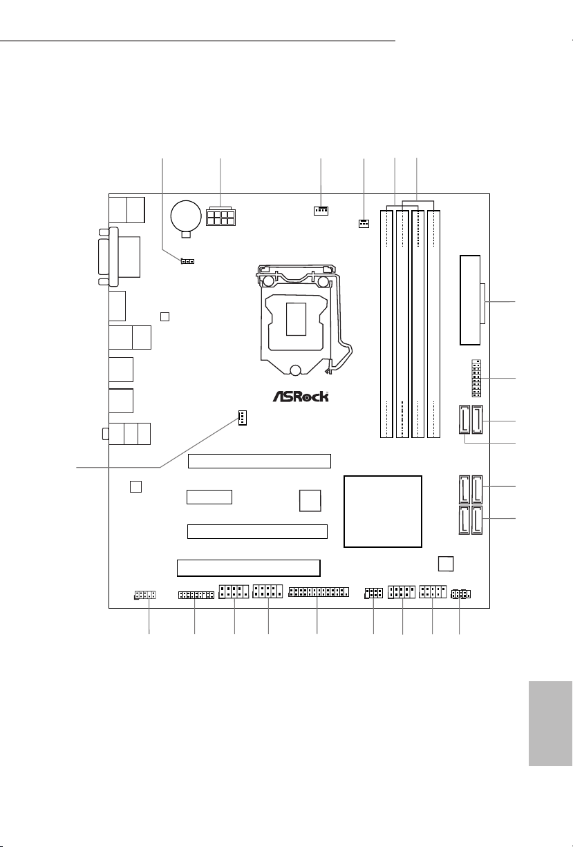
Motherboard Layout
B150M Pro4S/D3
English
1
Page 4

No. Description
1 Clear CMOS Jumper (CLRMOS1)
2 ATX 12V Power Connector (ATX12V1)
3 CPU Fan Connector (CPU_FAN1)
4 Chassis Fan Connector (CHA_FAN2)
5 2 x 240-pin DDR3/DDR3L DIMM Slots (DDR3_A1, DDR3_B1)
6 2 x 240-pin DDR3/DDR3L DIMM Slots (DDR3_A2, DDR3_B2)
7 ATX Power Connector (ATXPWR1)
8 USB 3.0 Header (USB_11_12)
9 SATA3 Connector (SATA 3_4)
10 SATA3 Connector (SATA3_5)
11 SATA3 Connectors (SATA3_0_2)
12 SATA3 Connectors (SATA3_1_3)
13 Chassis Intrusion and Speaker Header (SPK_CI1)
14 System Panel Header (PANEL1)
15 USB 2.0 Header (USB_9_10)
16 USB 2.0 Header (USB_7_8)
17 Print Port Header (LPT1)
18 COM Port Header (COM1)
19 COM Port Header (COM2)
20 TPM Header (TPMS1)
21 Front Panel Audio Header (HD_AUDIO1)
22 Chassis Fan Connector (CHA_FAN1)
English
2
Page 5

I/O Panel
2
3
1
B150M Pro4S/D3
4
11
10
9
8
7
6
No. Description No. Description
1 PS/2 Mouse Port (Green) 7 USB 3.0 Ports (USB_34)
2 LAN RJ-45 Port* 8 USB 2.0 Ports (USB_12)
3 Line In (Light Blue)** 9 HDMI Port
4 Front Speaker (Lime)** 10 DVI-D Port
5 Microphone (Pink)** 11 PS/2 Keyboard Port (Purple)
6 USB 3.0 Ports (USB_56)
* ere are two LEDs on each LAN port. Please refer to the table below for the LAN port LED indications.
ACT/LINK LED
SPEED LED
LAN Por t
Activity / Link LED Speed LED
Status Description Status Description
O No Link O 10Mbps connection
Blinking Data Activity Orange 100Mbps connection
On Link Green 1Gbps connection
5
English
3
Page 6
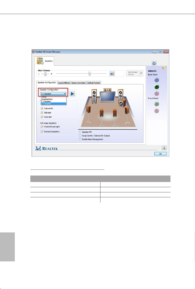
** To congure 7.1 CH HD Audio, it i s required to use an HD front panel audio module and enable the multichannel audio feature through the audio driver.
Please set Speaker Conguration to “7.1 Speaker”in the Realtek HD Audio Manager.
Function of the Audio Ports in 7.1-channel Conguration:
English
4
Port Function
Light Blue (Rear panel) Rear Speaker Out
Lime (Rear panel) Front Speaker Out
Pink (Rear panel) Central /Subwoofer Speaker Out
Lime (Front panel) Side Speaker Out
Page 7

B150M Pro4S/D3
Chapter 1 Introduction
ank you for purchasing ASRock B150M Pro4S/D3 motherboard, a reliable
motherboard produced under ASRock’s consistently stringent quality control.
It delivers excellent performance with robust design conforming to ASRock’s
commitment to quality and endurance.
Becau se the motherboard specications and the BIOS soware might be updated, the
content of this documentation will be subject to change without notice. In case any modications of this documentation occur, the updated version will be available on ASRock’s
website w ithout further notice. If you require technical support related to this motherboard, please visit our website for specic information about the model you are using. You
may nd the l atest VGA cards and CPU support list on ASRock’s website a s well. ASRock
website http://www.asrock.com.
1.1 Package Contents
•ASRock B150M Pro4S/D3 Motherboard (Micro ATX Form Factor)
•ASRock B150M Pro4S/D3 Quick Installation Guide
•ASRock B150M Pro4S/D3 Support CD
•2 x Serial ATA (SATA) Data Cables (Optional)
•1 x I/O Panel Shield
English
5
Page 8

1.2 Specications
Platform
CPU
Chipset
Memory
Expansion
Slot
•Micro ATX Form Factor
•Solid Capacitor design
•High Density Glass Fabric PCB
•Supports 6
Celeron® Processors (Socket 1151)
•Supports Intel® Turbo Boost 2.0 Technology
•Intel® B150
•Supports Intel® Small Business Advantage 4.0
•Dual Channel DDR3/DDR3L Memory Technology
•4 x DDR3/DDR3L DIMM Slots
•Supports DDR3/DDR3L 1866(OC)/1600/1333/1066 non-
ECC, un-buered memory
•Max. capacity of system memory: 64GB
•Supports Intel® Extreme Memory Prole (XMP) 1.3 / 1.2
•2 x PCI Express 3.0 x16 Slots (PCIE1: x16 mode; PCIE3: x4
mode)
•1 x PCI Express 3.0 x1 Slot (Flexible PCIe)
•1 x PCI Slot
* PCI cards that need subtractive decode are not supported.
•Supports AMD Quad CrossFireX
th
Generation Intel® CoreTM i7/i5/i3/Pentium®/
TM
and CrossFireXTM
English
6
Graphics
* Intel® HD Graphics Built-in Visuals and the VGA outputs can
be supported only with processors which are GPU integrated.
•Supports Intel® HD Graphics Built-in Visuals : Intel® Quick
Sync Video with AVC, MVC (S3D) and MPEG-2 Full
HW Encode1, Intel® InTruTM 3D, Intel® Clear Video HD
Technology, Intel® InsiderTM, Intel® HD Graphics 510/530
•Pixel Shader 5.0, DirectX 12
Page 9

B150M Pro4S/D3
•Max. shared memory 1792MB
•Dual graphics output: Support DVI-D and HDMI ports by
independent display controllers
•Supports HDMI with max. resolution up to 4K x 2K
(4096x2304) @ 24Hz
•Supports DVI-D with max. resolution up to 1920x1200 @
60Hz
•Supports Auto Lip Sync, Deep Color (12bpc), xvYCC and
HBR (High Bit Rate Audio) with HDMI Port
(Compliant HDMI monitor is required)
•Supports Accelerated Media Codecs: HEVC, VP8, VP9
•Supports HDCP with DVI-D and HDMI Ports
•Supports Full HD 1080p Blu-ray (BD) playback with DVI-D
and HDMI Ports
Audio
LAN
Rear Panel
I/O
•7.1 CH HD Audio with Content Protection (Realtek ALC892
Audio Codec)
* To congure 7.1 CH HD Audio, it is required to use an HD
front panel audio module and enable the multi-channel audio
feature through the audio driver.
•Premium Blu-ray Audio support
•Supports Surge Protection (ASRock Full Spike Protection)
•ELNA Audio Caps
•Gigabit LAN 10/100/1000 Mb/s
•Giga PHY Intel® I219V
•Supports Wake-On-LAN
•Supports Lightning/ESD Protection (ASRock Full Spike
Protection)
•Supports Energy Ecient Ethernet 802.3az
•Supports PXE
•1 x PS/2 Mouse Port
•1 x PS/2 Keyboard Port
•1 x DVI-D Port
English
7
Page 10

•1 x HDMI Port
•2 x USB 2.0 Ports (Supports ESD Protection (ASRock Full
Spike Protection))
•4 x USB 3.0 Ports (Supports ESD Protection (ASRock Full
Spike Protection))
•1 x RJ-45 LAN Port with LED (ACT/LINK LED and SPEED
LE D)
•HD Audio Jacks: Line in / Front Speaker / Microphone
Storage
Connector
BIOS
Feature
•6 x SATA3 6.0 Gb/s Connectors, support NCQ, AHCI and
Hot Plug
•1 x Print Port Header
•2 x COM Port Headers
•1 x TPM Header
•1 x Chassis Intrusion and Speaker Header
•1 x CPU Fan Connector (4-pin) (Smart Fan Speed Control)
•2 x Chassis Fan Connectors (1 x 4-pin, 1 x 3-pin) (Smart Fan
Speed Control)
•1 x 24 pin ATX Power Connector
•1 x 8 pin 12V Power Connector
•1 x Front Panel Audio Connector
•2 x USB 2.0 Headers (Support 4 USB 2.0 ports) (Supports
ESD Protection (ASRock Full Spike Protection))
•1 x USB 3.0 Header (Supports 2 USB 3.0 ports) (Supports
ESD Protection (ASRock Full Spike Protection))
•128Mb AMI UEFI Legal BIOS with multilingual GUI sup-
port
•ACPI 1.1 Compliant wake up events
•SMBIOS 2.3.1 Support
•CPU, GT_CPU, DRAM, PCH 1.0V, VCCIO, VCCSA Voltage
Multi-adjustment
English
8
Page 11
B150M Pro4S/D3
Hardware
Monitor
•CPU/Chassis temperature sensing
•CPU/Chassis Fan Tachometer
•CPU/Chassis Quiet Fan (Auto adjust chassis fan speed by
CPU temperature)
•CPU/Chassis Fan multi-speed control
•CASE OPEN detection
•Voltage monitoring: +12V, +5V, +3.3V, CPU Vcore, GT_CPU,
DRAM, PCH 1.0V, VCCIO, VCCSA
OS
•Microso® Windows® 10 64-bit / 8.1 64-bit / 7 32-bit / 7 64-
bit
* To install Windows® 7 OS, a modied installation disk with
xHCI drivers packed into the ISO le is required. Please refer to
page 143 for more detailed instructions.
* For the updated Windows® 10 driver, please visit ASRock 's
website for details: http://www.asrock.com
Certications
* For detailed product information, please visit our website: http://www.asrock.com
•FCC, CE, WHQL
•ErP/EuP ready (ErP/EuP ready power supply is required)
Please realize that the re is a certain risk involved with overclocking, including adjusting
the setting in the BIOS, applying Untied Overclocking Technolog y, or using third-party
overclocking tools. O verclocking may aect your system’s stability, or even cause damage to
the components and devices of your system. It should be done at your ow n risk and expense.
We are not responsible for possible damage caused by overclocking.
English
9
Page 12

Chapter 2 Installation
is is a Micro ATX form factor motherboard. Before you install the motherboard,
study the conguration of your chassis to ensure that the motherboard ts into it.
Pre-installation Precautions
Take note of the following precautions before you install motherboard components
or change any motherboard settings.
•Make sure to unplug the power cord before installing or removing the motherboard
components. Failure to do so may cause physical injuries and damages to motherboard
components.
•In order to avoid damage from static electricity to the motherboard’s components,
NEVER place your motherboard directly on a carpet. Also remember to use a grounded
wrist strap or touch a safety grounded object before you handle the components.
•Hold components by the edges and do not touch the ICs.
•Whenever you uninstall any components, place them on a grounded anti-static pad or
in the bag that comes with the components.
•When placing screws to secure the motherboard to the chassis, please do not over-
tighten the screws! Doing so may damage the motherboard.
English
10
Page 13
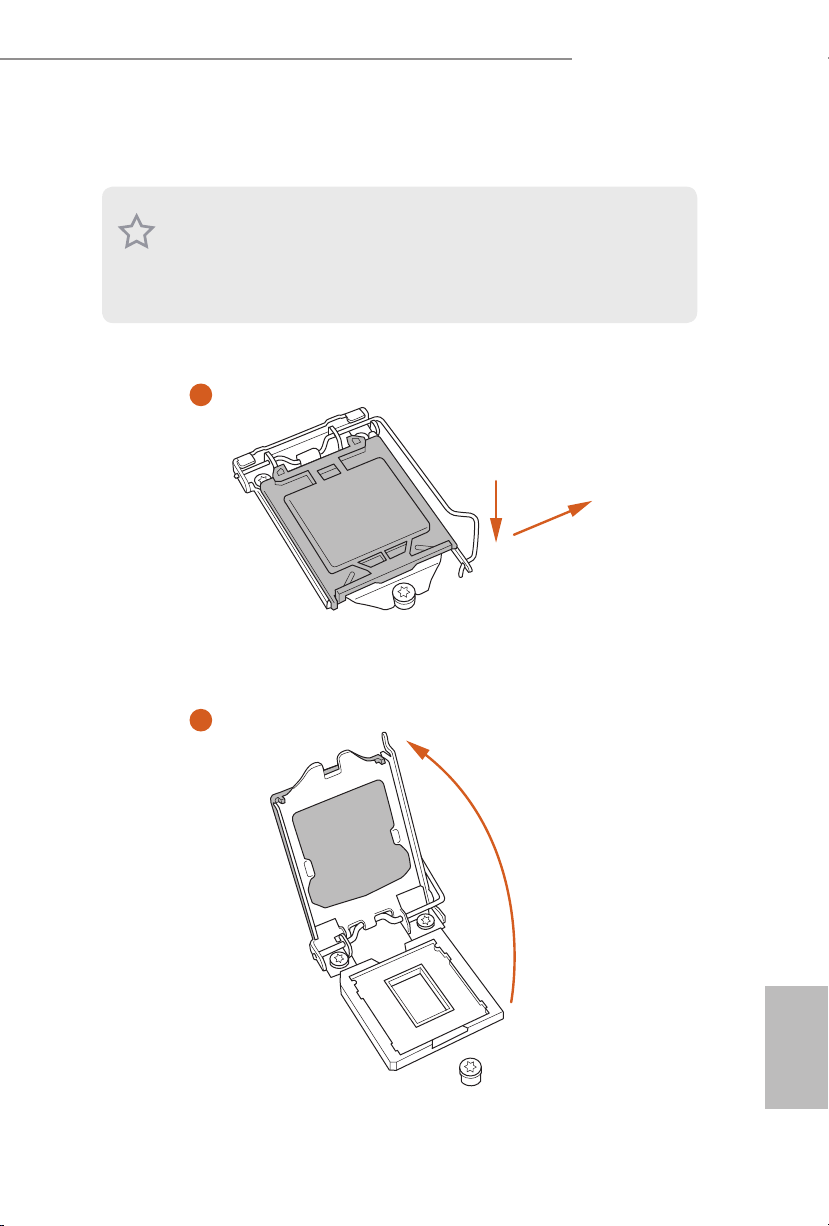
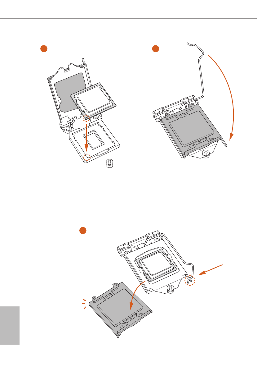
2.1 Installing the CPU
1. Before you insert the 1151-Pin CPU into the socket, please check if the PnP cap is on the
socket, if the CPU surface is unclean, or if there are any bent pins in the sock et. Do not
force to in sert the CPU into the socket if above situation is found. Otherwise, the CPU
will be seriously damaged.
2. Unplug all power cables before in stalling the CPU.
1
B150M Pro4S/D3
A
B
2
English
11
Page 14
3
4
English
12
5
Page 15

B150M Pro4S/D3
Please save and replace the cover if the processor i s removed. e cover must be placed if
you wish to return the motherboard for aer service.
13
English
Page 16
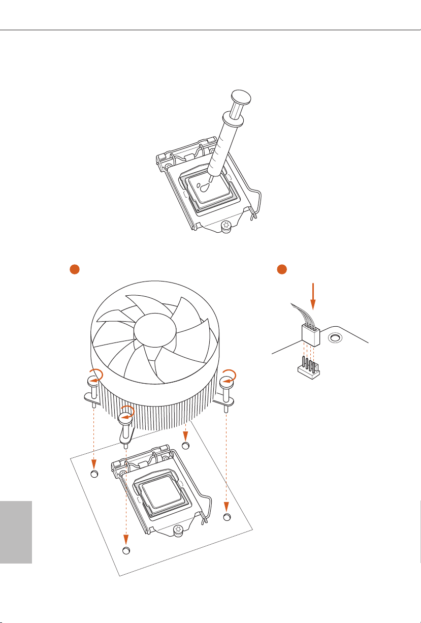
2.2 Installing the CPU Fan and Heatsink
1 2
English
14
FAN
CPU_
Page 17
B150M Pro4S/D3
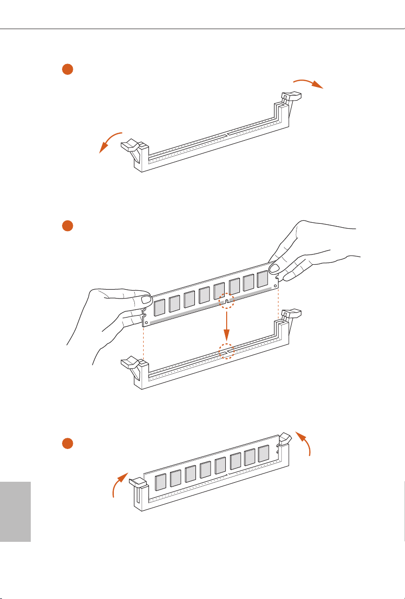
2.3 Installing Memory Modules (DIMM)
is motherboard provides four 240-pin DDR3/DDR3L (Double Data Rate 3)
DIMM slots, and supports Dual Channel Memory Technology.
1. For dual channel conguration , you always need to in stall identical (the same brand,
speed , size and chip-type) DDR3/DDR3L DIMM pairs.
2. It is unable to activate Du al Channel Memory Technology with only one memory module
installed.
3. It is not allowed to install a DDR or DDR2 memory module into a DDR3/DDR3L slot;
otherwise, this motherboard and DIMM may be damaged..
Dual Channel Memory Conguration
Priority DDR3_A1 DDR3_A2 DDR3_B1 DDR3_B2
1 Populated Populated
2 Populated Populated
3 Populated Populated Populated Populated
e DIMM only ts in one correct orientation. It will cause permanent damage to the
motherboard and the DIMM if you force the DIMM into the slot at incorrect orientation.
English
15
Page 18
1
2
English
16
3
Page 19

B150M Pro4S/D3
2.4 Expansion Slots (PCI and PCI Express Slots)
ere is 1 PCI slot and 3 PCI Express slots on the motherboard.
Before installing an ex pansion card, please make sure that the power supply is switched o
or the power cord is unplugged. Please read the documentation of the expansion card and
make necessary hardware settings for the card before you start the installation.
PCI slot:
e PCI1 is used to install expansion cards that have 32-bit PCI interface.
PCIe slots:
PCIE1 (PCIe 3.0 x16 slot) is used for PCI Express x16 lane width graphics cards.
PCIE2 (PCIe 3.0 x1 slot) is used for PCI Express x1 lane width cards.
PCIE3 (PCIe 3.0 x16 slot) is used for PCI Express x4 lane width graphics cards.
17
English
Page 20
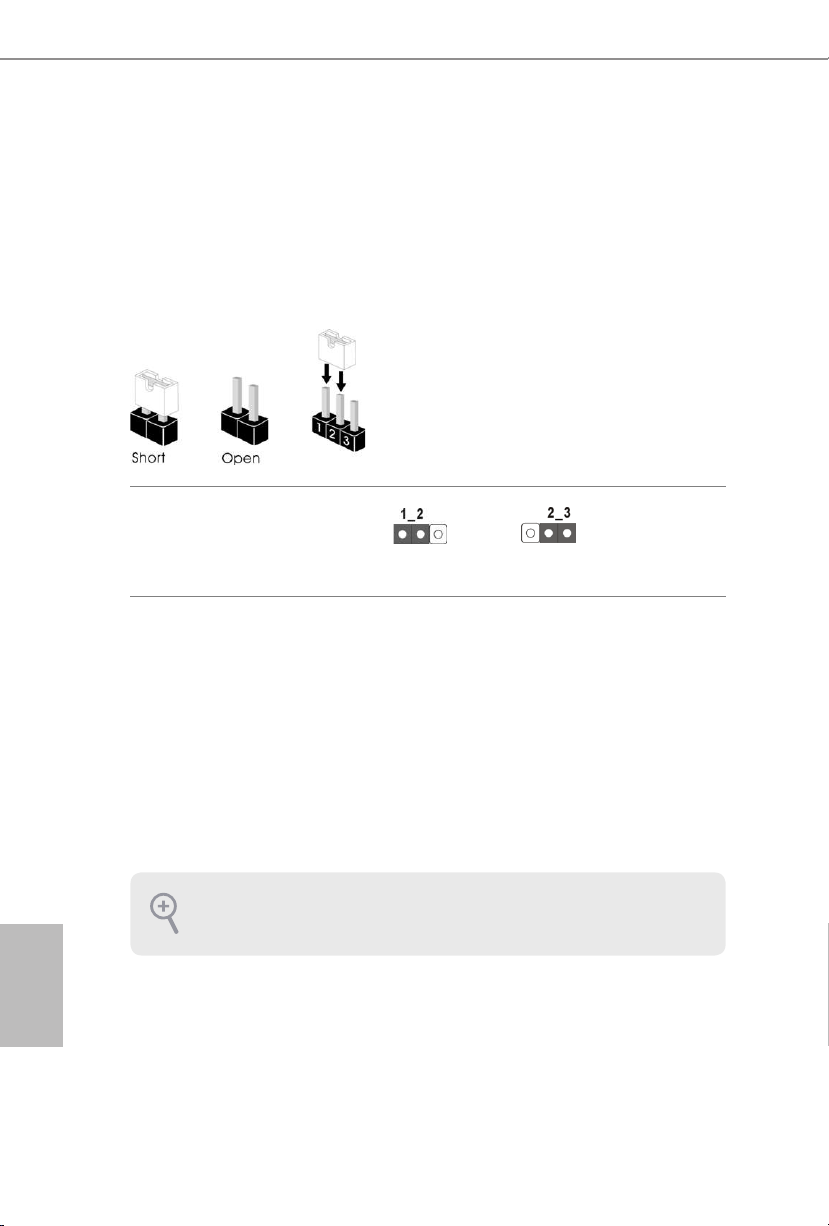
2.5 Jumpers Setup
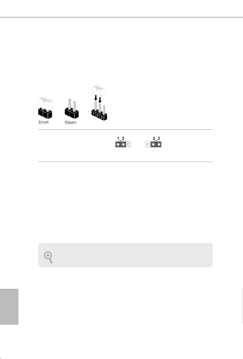
e illustration shows how jumpers are setup. When the jumper cap is placed on
the pins, the jumper is “Short”. If no jumper cap is placed on the pins, the jumper
is “Open”. e illustration shows a 3-pin jumper whose pin1 and pin2 are “Short”
when a jumper cap is placed on these 2 pins.
Clear CMOS Jumper
(C LR MOS 1)
(see p.1, No. 1)
CLRMOS1 allows you to clear the data in CMOS. To clear and reset the system
parameters to default setup, please turn o the computer and unplug the power
cord from the power supply. Aer waiting for 15 seconds, use a jumper cap to
short pin2 and pin3 on CLRMOS1 for 5 seconds. However, please do not clear the
CMOS right aer you update the BIOS. If you need to clear the CMOS when you
just nish updating the BIOS, you must boot up the system rst, and then shut it
down before you do the clear-CMOS action. Please be noted that the password,
date, time, and user default prole will be cleared only if the CMOS battery is
removed.
Clear CMOSDefault
English
18
If you clear the CMOS, the case open may be detec ted. Please adjust the BIOS option “Clear
Status” to clear the record of previous chassis intrusion status.
Page 21
2.6 Onboard Headers and Connectors
Onboard headers and connectors are NOT jumpers. Do NOT place jumper caps over these
heade rs and connectors. Placing jumper caps over the headers and connectors will cause
permanent damage to the motherboard.
B150M Pro4S/D3
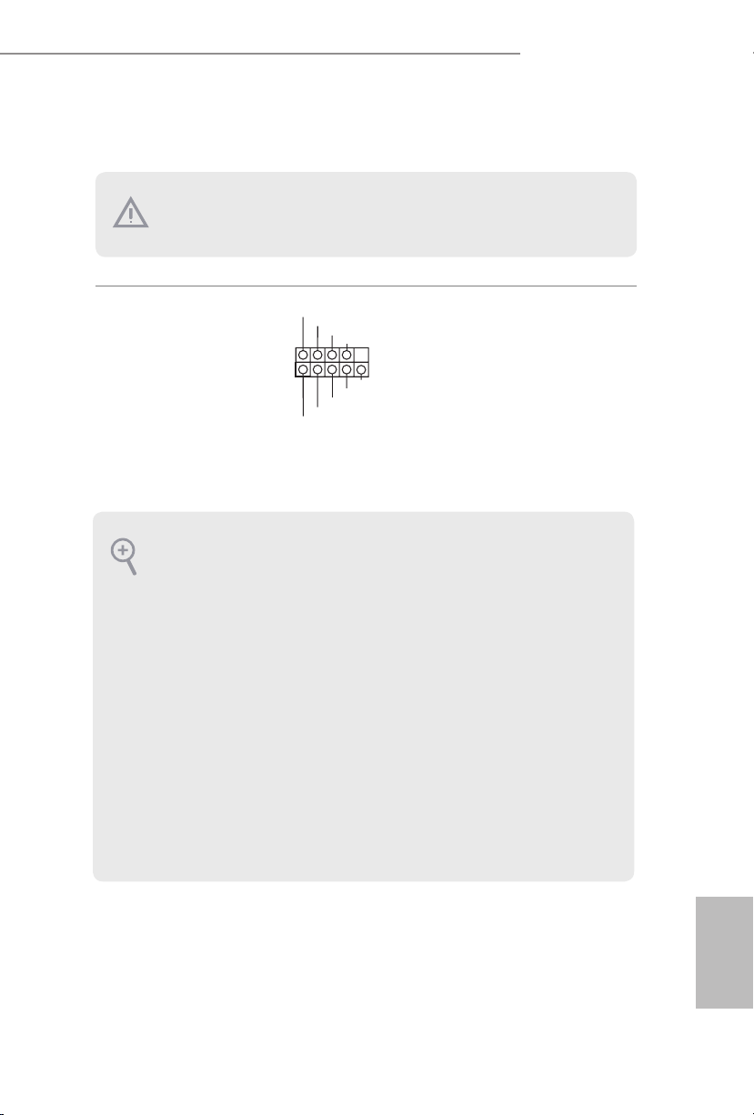
1
PLED+
PLED-
HDLED-
HDLED+
PWRBTN#
GND
RESET#
GND
GND
Connect the power
switch, reset switch and
system status indicator on
the chassis to this header
according to the pin
assignments below. Note
System Panel Header
(9-pi n PANEL1)
(see p.1, No. 13)
the positive and negative
pins before connecting
the cables.
PWRBTN (Power Switch):
Connec t to the power switch on the chassi s front panel. You may congure the way to tur n
o your system using the power switch.
RESET (Reset Switch):
Connec t to the reset switch on the chassis front panel. Press the reset sw itch to restart the
computer if the computer f reezes and fails to perform a normal restar t.
PLED (Syste m Power LED):
Connec t to the power status indicator on the chassis front panel. e LED i s on when the
system is operating. e LED keeps blinking when the system is in S1/S3 sleep state. e
LED is o when the system is in S4 sleep state or powered o (S5).
HDLED (Ha rd Drive Activity LED):
Connec t to the hard drive activity LED on the chassis front panel. e LED is on when the
hard drive is reading or wr iting data.
e front panel design may dier by chassis. A front panel module mainly consists of power
switch, reset switch , power LED, hard dr ive activity LED, speaker and etc. When connecting your chassi s front panel module to thi s header, make sure the wire a ssignments and the
pin assignments are matched correctly.
19
English
Page 22
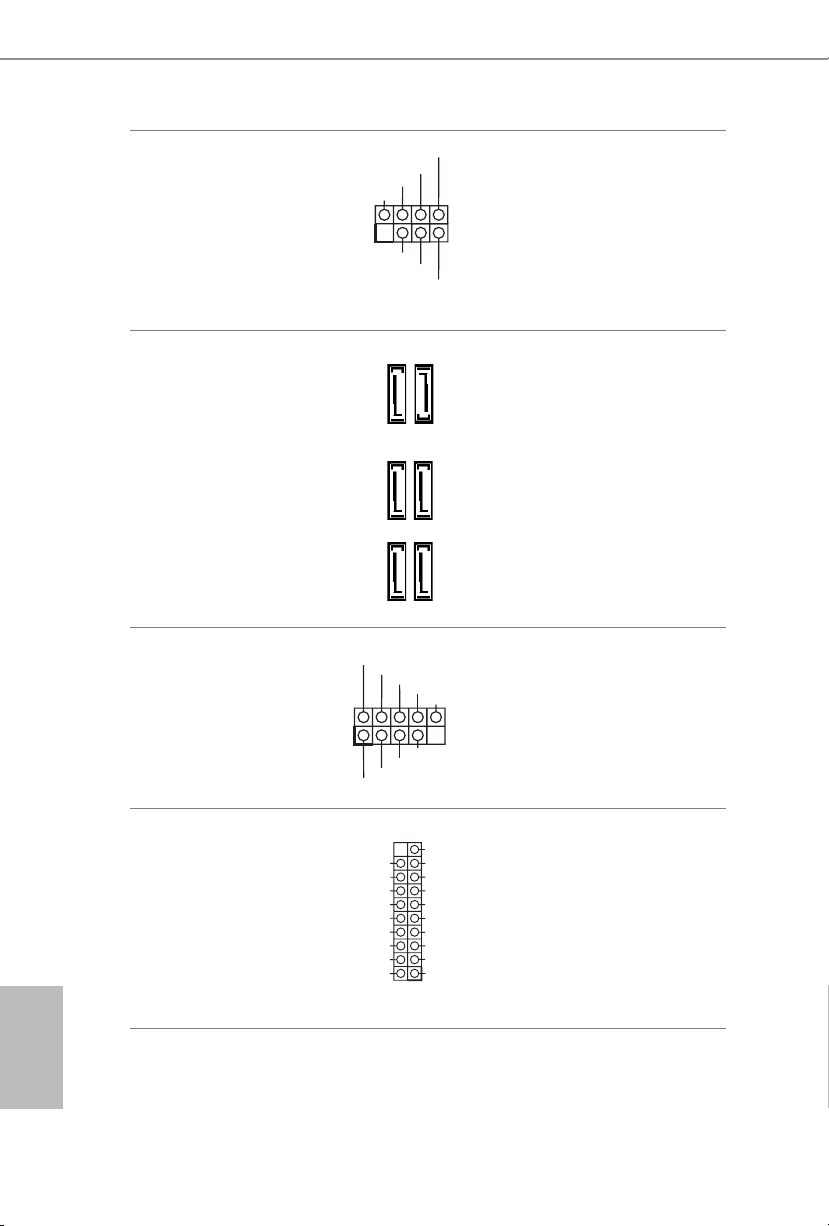
Chassis Intrusion and
SPEAKER
Speaker Header
(7-pi n SPK_CI1)
(see p.1, No. 16)
DUMMY
+5V
1
SIGNAL
DUMMY
GND
DUMMY
Please connect the
chassis intrusion and the
chassis speaker to this
header.
English
Serial ATA3 Connectors
(SATA3_4)
(see p.1, No. 9)
(SATA3_ 5)
(see p.1, No. 10)
(SATA3_ 0_2)
(see p.1, No. 11)
(SATA 3_1_3)
(see p.1, No. 12)
USB 2.0 Headers
(9-pin USB_7_8)
(see p.1, No. 15)
(9-pin USB_9_10)
(see p.1, No. 14)
USB 3.0 Header
(19-pin USB11_12)
(see p.1, No. 8)
USB_PWR
1
USB_PWR
Vbus
IntA_PA_SSRX-
IntA_PA_SSRX+
GND
IntA_PA_SSTX-
IntA_PA_SSTX+
GND
IntA_PA_D-
IntA_PA_D+
SATA3_5
SATA3_2
SATA3_3
-B
-A
+B
+A
GND
DUMMY
GND
VbusVbus
IntA_PB_SSRX-
IntA_PB_SSRX+
GND
IntA_PB_SSTX-
IntA_PB_SSTX+
GND
IntA_PB_D-
IntA_PB_D+
Dummy
1
ese six SATA3
connectors support SATA
data cables for internal
SATA3_4
storage devices with up to
6.0 Gb/s data transfer rate.
SATA3_0
SATA3_1
ere are two headers
on this motherboard.
Each USB 2.0 header can
support two ports.
Besides four USB 3.0
ports on the I/O panel,
there is one header on this
motherboard. Each USB
3.0 header can support
two ports.
20
Page 23

B150M Pro4S/D3
GND
4 3 2 1
Front Panel Audio Header
(9-pin HD_ AUDIO1)
(see p.1, No. 21)
1. High Denition Audio support s Jack Sensing, but the panel wire on the chassis must sup port HDA to function correctly. Please follow the instructions in our manual and chassis
manual to install your system.
2. If you use an AC’97 audio panel , please install it to the front panel audio header by the
steps below:
A. Connect Mic_IN (MIC) to MIC2_ L.
B. Conne ct Audio_R (RIN) to OUT2_R and Audio_ L (LIN) to OUT2_ L.
C. Connect Ground (GND) to Ground (GND).
D. MIC_ RET and OUT_RET are for the HD audio panel only. You don’t need to connect
them for the AC’97 audio panel .
E. To activate the front mic, go to the “FrontMic” Tab in the Realtek Control panel and
adjust “Recording Volume”.
Chassis Fan Connectors
(4-pin CHA_FAN1)
(see p.1, No. 22)
GND
PRESENCE#
MIC_RET
OUT_RET
1
OUT2_L
J_SENSE
OUT2_R
MIC2_R
MIC2_L
FAN_VOLTAGE
CHA_FAN_SPEED
FAN_SPEED_CONTROL
is header is for
connecting audio devices
to the front audio panel.
Please connect fan cables
to the fan connector and
match the black wire to
the ground pin.
(3-pi n CHA_FAN2)
(see p.1, No. 4)
CPU Fan Connector
(4-pin CPU_FAN1)
(see p.1, No. 3)
GND
FAN_VOLTAGE
CPU_FAN_SPEED
FAN _SPEED_ CONTROL
is motherboard pro-
vides a 4-Pin CPU fan
(Quiet Fan) connector.
If you plan to connect a
3-Pin CPU fan, please
connect it to Pin 1-3.
English
21
Page 24

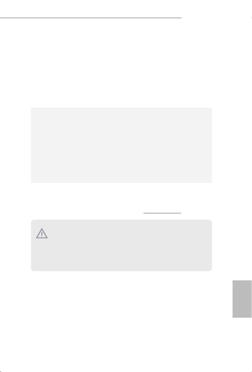
ATX Power Connector
AFD#
(24-pin ATXPWR1)
(see p.1, No. 7)
1
13
is motherboard provides a 24-pin ATX power
connector. To use a 20-pin
ATX power supply, please
plug it along Pin 1 and Pin
13.
12
24
English
ATX 12V Power
Connector
(8-pin ATX12V1)
(see p.1, No. 2)
Serial Port Headers
(9-pin COM1)
(see p.1, No. 18)
(9-pin COM2)
(see p.1, No. 19)
TPM Header
(17-pi n TPMS1)
(see p.1, No. 20)
Print Port Header
(25-pin LPT1)
(see p.1, No. 17)
8 5
is motherboard provides a 8-pin ATX 12V
GND
1
SMB _DATA_MA IN
SMB _CLK_ MAIN
4 1
RRXD1
DDTR#1
DDSR#1
CCTS#1
RRTS#1
GND
TTXD1
DDCD#1
LAD 1_L
LAD 2_L
GND
RRI#1
S_P WRDWN #
power connector.
e COM1 and COM2
headers support a serial
port module.
is connector supports Trusted
SER IRQ#
Platform Module (TPM) system,
which can securely store keys,
digital certicates, passwords,
1
LAD 3_L
CK_ 33M_T PM
+3V
TPM _RST#
LFR AME#_ L
LAD 0_L
and data. A TPM system also
helps enhance network security,
GNDF_C LKRUN #
+3V SB
protects digital identities, and
ensures platform integrity.
ERROR#
PINIT#
1
SPD1
SPD0
STB#
SLIN#
SPD2
SPD3
SPD4
SPD5
SPD6
GND
SPD7
ACK#
BUSY
is is an interface for printport
cable that allows conve-nient
connection of printerdevices
PE
SLCT
22
Page 25

B150M Pro4S/D3
1 Einleitung
Vielen Dank, dass Sie sich für das B150M Pro4S/D3 von ASRock entschieden
haben – ein zuverlässiges Motherboard, das konsequent unter der strengen
Qualitätskontrolle von ASRock hergestellt wurde. Es liefert ausgezeichnete Leistung
mit robustem Design, das ASRock Streben nach Qualität und Beständigkeit erfüllt.
Da die technischen Daten des Motherboards sowie die BIOS-Soware aktualisiert werden
können, kann der Inhalt dieser Dokumentation ohne Ankündigung geändert we rden.
Falls diese Dokumentation irgendwelchen Änderungen unterliegt, wird die aktualisierte
Version ohne weitere Hinweise auf der ASRock-Webseite zur Verfügung gestellt. Sollten Sie
technische Hilfe in Bezug auf dieses Motherboard benötigen, erhalten Sie auf unserer Webseite spezischen Informationen über das von Ihnen verwendete Modell. Auch nden Sie
eine aktuelle Liste unterstützter VGA-Karten und Prozessoren auf der ASRock-Webseite:
ASRock-Website http://www.asrock .com.
1.1 Lieferumfang
•ASRock B150M Pro4S/D3-Motherboard (Micro-ATX-Formfaktor)
•ASRock B150M Pro4S/D3-Schnellinstallationsanleitung
•ASRock B150M Pro4S/D3-Support-CD
•2 x Serial-ATA- (SATA) Datenkabel (optional)
•1 x E/A-Blendenabschirmung
23
Deutsch
Page 26

1.2 Technische Daten
Plattform
Prozessor
Chipsatz
Speicher
Erweiterungssteckplatz
•Micro-ATX-Formfaktor
•Feststoondensator-Design
•Leiterplatte mit hochdichtem Glasgewebe
•Unterstützt die Prozessoren Intel® Core
Pentium®/Celeron® der 6. Generation (Sockel 1151)
•Unterstützt Intel® Turbo Boost 2.0-Technologie
•Intel® B150
•Unterstützt Intel® Small Business Advantage 4.0
•Dualkanal-DDR3/DDR3L-Speichertechnologie
•4 x DDR3/DDR3L-DIMM-Steckplätze
•Unterstützt DDR3/DDR3L 1866(OC)/1600/1333/1066
non-ECC,
ungepuerter Speicher
•Systemspeicher, max. Kapazität: 64GB
•Unterstützt Intel® Extreme Memory Prole (XMP) 1.3 / 1.2
•2 x PCI-Express 3.0-x16-Steckplatz (PCIE1:x16-Modus;
PCIE3:x4-Modus)
•1 x PCI-Express 3.0-x1-Steckplatz (Flexible PCIe)
•1 x PCI-Steckplatz
* PCI-Karten, die eine subtraktive Dekodierung benötigen,
werden nicht unterstützt.
•Unterstützt AMD Quad CrossFireX
TM
i7/i5/i3/
TM
und CrossFireXTM
Deutsch
24
Grakkarte
* Integrierte Intel® HD Graphics-Visualisierung und
VGA-Ausgänge können nur mit Prozessoren unterstützt
werden, die GPU-integriert sind.
•Unterstützt integrierte Intel® HD Graphics-Visualisierung:
Intel® Quick Sync Video mit AVC, MVC (S3D) und
MPEG-2 Full HW Encode1, Intel® InTruTM 3D, Intel® Clear
Video HD Technology, Intel® InsiderTM, Intel® HD
Graphics 510/530
•Pixel Shader 5.0, DirectX 12
Page 27

B150M Pro4S/D3
•Max. geteilter Speicher: 1792 MB
•Dualer Grakkartenausgang Unterstützt DVI-D- und
HDMI-Ports durch unabhängige Monitor-Controller
•Unterstützt HDMI mit maximaler Auösung von 4K x 2K
(4096 x 2304) bei 24 Hz
•Unterstützt DVI-D mit maximaler Auösung von
1920 x 1200 bei 60 Hz
•Unterstützt Auto-Lippensynchronizität, hohe Farbtiefe
(12 bpc), xvYCC und HBR (Audio mit hoher Bitrate) mit
HDMI-Port(konformer HDMI-Monitor erforderlich)
•Unterstützt beschleunigte Mediencodecs: HEVC,
VP8, VP9
•Unterstützt HDCP mit DVI-D- und HDMI-Ports
•Unterstützt Blu-ray- (BD) Wiedergabe (Full HD/1080p)
mit DVI-D- und HDMI-Ports
Audio
LAN
Rückblende, E/A
•7.1-Kanal-HD-Audio mit Inhaltsschutz (Realtek
ALC892-Audiocodec)
*Zur Konguration von 7.1-Kanal-HD-Audio müssen
Sie ein HD-Frontblenden-Audiomodul nutzen und den
Mehrkanalton über den Audiotreiber aktivieren.
•Erstklassige Blu-ray-Audiounterstützung
•Unterstützt Überspannungsschutz (ASRock Full
Spike Protection)
•ELNA-Audiokondensatoren
•Gigabit LAN 10/100/1000 Mb/s
•Giga PHY Intel® I219V
•Unterstützt Wake-On-LAN
•Unterstützt Blitzschutz/Schutz gegen elektrostatische
Entladung (ASRock Full Spike Protection)
•Unterstützt energieezientes Ethernet 802.3az
•Unterstützt PXE
•1 x PS/2-Mausanschluss
•1 x PS/2-Tastaturanschluss
•1 x DVI-D-Port
Deutsch
25
Page 28

•1 x HDMI-Port
•2 x USB 2.0-Ports (unterstützt Schutz gegen elektrostatische
Entladung (ASRock Full Spike Protection))
•4 x USB 3.0-Ports (unterstützt Schutz gegen elektrostatische
Entladung (ASRock Full Spike Protection))
•1 x RJ-45-LAN-Port mit LED (Aktivität/Verbindung-LED
und Geschwindigkeit-LED)
•HD-Audioanschlüsse: Line-in / Vorderer Lautsprecher /
Mikrofon
Deutsch
Speicher
Anschluss
BIOSFunktion
•6 x SATA-III-6,0-Gb/s-Anschlüsse, unterstützt NCQ, AHCI
und Hot-Plugging
•1 Druckerport-Anschlussleiste
•2 x COM-Anschluss-Stileiste
•1 x TPM-Stileiste
•1 x Gehäuseeingri- und Lautsprecher-Stileiste
•1 x CPU-Lüeranschluss (4-polig) (intelligente
Lüergeschwindigkeitssteuerung)
•2 x Gehäuselüeranschlüsse (1 x 4-polig, 1 x 3-polig)
(intelligente Lüergeschwindigkeitssteuerung)
•1 x 24-poliger ATX-Netzanschluss
•1 x 8-poliger 12-V-Netzanschluss
•1 x Audioanschluss an Frontblende
•2 x USB 2.0-Stileisten (unterstützen 4 USB 2.0-Ports)
(unterstützt Schutz gegen elektrostatische Entladung (ASRock
Full Spike Protection))
•1 x USB 3.0-Stileiste (unterstützt 2 USB 3.0-Ports)
(unterstützt Schutz gegen elektrostatische Entladung (ASRock
Full Spike Protection))
•128-Mb-AMI-UEFI-Legal-BIOS mit Unterstützung
mehrsprachiger grascher Benutzerschnittstellen
•ACPI 1.1-konforme Aufweckereignisse
•SMBIOS 2.3.1-Unterstützung
•CPU, GT_CPU, DRAM, PCH 1,0V, VCCIO, VCCSA
Mehrfachspannungsanpassung
26
Page 29
B150M Pro4S/D3
Hardwareüberwachung
•CPU-/Gehäusetemperaturerkennung
•CPU-/Gehäuselüertachometer
•Lautloser CPU-/Gehäuselüer (automatische Anpassung der
Gehäuselüergeschwindigkeit durch CPU-Temperatur)
•CPU-/Gehäuselüer-Mehrfachgeschwindigkeitssteuerung
•Gehäuse-oen-Erkennung
•Spannungsüberwachung: +12 V, +5 V, +3,3 V, CPU Vcore,
GT_CPU, DRAM, PCH 1,0 V, VCCIO, VCCSA
Betriebssystem
•Microso® Windows® 10, 64 Bit / 8.1, 64 Bit / 7, 32 Bit / 7, 64
Bit
* Zur Installation des Windows® 7-Betriebssystems wird ein
modiziertes Installationslaufwerk mit xHCI-Treibern in der
ISO-Datei benötigt. Detaillierte Anweisungen nden Sie
auf Seite 143.
* Einzelheiten zum aktualisierten Windows® 10-Treiber
entnehmen Sie bitte der ASRock-Webseite:
http://www.asrock.com
Zertizierungen
* Detaillierte Produktinformationen nden Sie auf unsere r Webseite: http://www.asrock.com
•FCC, CE, WHQL
•ErP/EuP ready (ErP/EuP ready-Netzteil erforderlich)
Bitte beachten Sie, da ss mit einer Übertaktung, zu der die Anpassung von BIOS -Einstellungen , die Anwendung der Untied Overclocking Technology oder die Nutzung von
Übertaktungswerkzeugen von Drittanbietern zählen, bestimmte Risiken verbunden
sind. Eine Übe rtaktung kann sich auf die Stabilität Ihres Systems auswirken und sogar
Kompone nten und Geräte Ihres Systems beschädigen. Sie sollte auf eigene Gefahr und
eigene Kosten durchgef ührt werden. Wir übernehmen keine Verantwortung für mögliche
Schäden, die durch eine Übertaktung verursacht wurden.
Deutsch
27
Page 30
1.3 Jumpereinstellung
Die Abbildung zeigt, wie die Jumper eingestellt werden. Wenn die Jumper-Kappe
auf den Kontakten angebracht ist, ist der Jumper „kurzgeschlossen“. Wenn keine
Jumper-Kappe auf den Kontakten angebracht ist, ist der Jumper „oen“. Die
Abbildung zeigt einen 3-poligen Jumper, dessen Kontakt 1 und Kontakt 2
„kurzgeschlossen“ sind, wenn eine Jumper-Kappe auf diesen 2 Kontakten
angebracht ist.
CMOS-löschen-Jumper
(C LR MOS 1)
(siehe S. 1, Nr. 1)
CLRMOS1 ermöglicht Ihnen die Löschung der Daten im CMOS. Zum Löschen
und Rücksetzen der Systemparameter auf die Standardeinrichtung schalten Sie
den Computer bitte ab und ziehen das Netzkabel aus der Steckdose. Warten Sie 15
Sekunde, schließen Sie dann Kontakt 2 und Kontakt 3 an CLRMOS1 5 Sekunden
lang mit einer Jumper-Kappe kurz. Löschen Sie den CMOS jedoch nicht direkt
nach der BIOS-Aktualisierung. Falls Sie den CMOS direkt nach Abschluss der
BIOS-Aktualisierung löschen müssen, starten Sie das System zunächst; fahren Sie
es dann vor der CMOS-Löschung herunter. Bitte beachten Sie, dass Kennwort,
Datum, Zeit und Benutzerstandardprol nur gelöscht werden, wenn die CMOSBatterie entfernt wird.
Standard
CMOS löschen
Deutsch
28
Falls Sie den CMOS löschen, wird möglicherweise ein Gehäuseeing ri erkannt. Bitte pa ssen Sie die BIOS-Option „Status löschen“ zur Löschung der Aufzeichnung des vorherigen
Gehäuseeingristatus an.
Page 31

1.4 Integrierte Stiftleisten und Anschlüsse
Integrierte Stile isten und Anschlüsse sind KEINE Jumper. Bringen Sie KEINE
Jumper-Kappen an diesen Stileisten und Anschlüssen an. Durch Anbringen von JumperKappen an diesen Stileisten und Anschlüssen können Sie das Motherboard
dauerha beschädigen.
B150M Pro4S/D3
Systemblende-Stileiste
(9-polig, PANEL1)
(siehe S. 1, Nr. 13)
PWRBTN (Ein-/Austaste):
Mit der Ein-/Austaste an der Frontblende des Gehäuses verbinden . Sie können die Abschaltung Ihres Systems über die Ein-/Austaste kongur ieren.
RESET (Reset-Taste):
Mit der Reset-Taste an der Frontblende des Gehäu ses verbinden. Star ten Sie den Computer
über die Reset-Taste neu, wenn er abstürzt oder sich nicht normal neu starten lässt.
PLED (Systembetriebs-LED):
Mit der Betriebsstatusanz eige an der Frontblende des Gehäuses verbinden. Die LED
leuchtet, wenn das System läu. Die LED blinkt, wenn sich das System im S1/S3-Ruhezustand bendet. Die LED ist aus, wenn sich das System im S4-Ruhezu stand bendet oder
ausgeschaltet ist (S5).
HDLED (Festplattenaktivitäts-LED):
Mit der Festplattenaktivitäts-LED an der Frontblende des Gehäuses verbinden. Die LED
leuchtet, wenn die Fest platte Daten liest oder schre ibt.
Das Design de r Frontblende kann je nach Gehäu se variieren. Ein Frontblendenmodul
besteht hauptsächlich aus Ein-/Austaste, Reset-Taste, Betrieb-LED, FestplattenaktivitätLED, Lautsprecher etc. Stellen Sie beim Anschließen Ihres Frontblendenmoduls an diese
Stileiste sicher, dass Kabel- und Pinbelegung richtig abgestimmt sind.
1
PLED+
PLED-
HDLED-
HDLED+
PWRBTN#
GND
RESET#
GND
GND
Verbinden Sie
Netzschalter, Reset-Taste
und Systemstatusanzeige
am Gehäuse entsprechend
der nachstehenden
Pinbelegung mit dieser
Stileiste. Beachten Sie
vor Anschließen der
Kabel die positiven und
negativen Kontakte.
29
Deutsch
Page 32

Gehäuseeingris- und
SPEAKER
Lautsprecher-Stileiste
(7-pol ig, SPK _CI1)
(siehe S. 1, Nr. 16)
DUMMY
+5V
1
SIGNAL
DUMMY
GND
DUMMY
Bitte verbinden Sie
Gehäuseeingrisvorrichtung und den
Gehäuselautsprecher mit
dieser Stileiste.
Deutsch
Serial-ATA-IIIAnschlüsse
(SATA3_ 4)
(siehe S. 1, Nr. 9)
(SATA3_ 5)
(siehe S. 1, Nr. 10)
(SATA3_ 0_2)
(siehe S. 1, Nr. 11)
(SATA 3_1_3)
(siehe S. 1, Nr. 12)
USB 2.0-Stileisten
(9-polig, USB_7_8)
(siehe S. 1, Nr. 15)
(9-polig, USB_9_10)
(siehe S. 1, Nr. 14)
USB 3.0-Stileiste
(19-polig, USB11_12)
(siehe S. 1, Nr. 8)
USB_PWR
1
USB_PWR
Vbus
IntA_PA_SSRX-
IntA_PA_SSRX+
GND
IntA_PA_SSTX-
IntA_PA_SSTX+
GND
IntA_PA_D-
IntA_PA_D+
SATA3_5
SATA3_2
SATA3_3
-B
-A
+B
+A
GND
DUMMY
GND
VbusVbus
IntA_PB_SSRX-
IntA_PB_SSRX+
GND
IntA_PB_SSTX-
IntA_PB_SSTX+
GND
IntA_PB_D-
IntA_PB_D+
Dummy
1
Diese sechs SATA-IIIAnschlüsse unterstützen
SATA-Datenkabel für
interne Speichergeräte mit
SATA3_4
einer Datenübertragungs
geschwindigkeit bis
6,0 Gb/s.
SATA3_0
SATA3_1
Es gibt zwei Stileisten an
diesem Motherboard. Jede
USB 2.0-Stileiste kann
zwei Ports unterstützen.
Neben vier USB 3.0-Ports
an der E/A-Blende
bendet sich eine
Stileiste an diesem
Motherboard. Jede USB
3.0-Stileiste kann zwei
Ports unterstützen.
30
Page 33

B150M Pro4S/D3
4 3 2 1
Audiostileiste
(Frontblende)
(9-polig, HD_AUDIO1)
(siehe S. 1, Nr. 21)
1. High Denition Audio unterstützt Anschlusserkennung, der Draht am Gehäuse muss
dazu jedoch HDA unterstützt. Bitte befolgen Sie zum Installieren Ihre s Systems die
Anweisungen in unserer Anleitung und der Anleitung zum Gehäuse.
2. Bei Nutzung eines AC’97-Audiopanels diese s bitte anhand folgender Schr itte an der
Audiostileiste der Frontblende installieren:
A. Mic_ IN (Mikrofon) mit MIC2_L verbinden.
B. Audio_ R (RIN) mit OUT2_R und Audio_ L (LIN) mit OUT2_L verbinden.
C. Erde (GND) mit Erde (GND) verbinden.
D. MIC_ RET und OUT_RET sind nur für das HD-Audiopanel vorgesehen. Sie müssen
sie nicht für das AC’97-Audiopanel verbinden.
E. Rufen Sie zum Aktivieren des vorderen Mikrofons das „FrontMic (Vorderes
Mikrofon)“-Register in der Realtek-Systemsteuerung auf und pa ssen „Recording Volume
(Aufnahmelautstärke)“ an.
Gehäuselüeranschlüsse
(4-polig, CHA_FAN1)
(siehe S. 1, Nr. 22)
GND
PRESENCE#
MIC_RET
OUT_RET
1
OUT2_L
J_SENSE
OUT2_R
MIC2_R
MIC2_L
GND
FAN_VOLTAGE
CHA_FAN_SPEED
FAN_SPEED_CONTROL
Diese Stileiste dient
dem Anschließen von
Audiogeräten an der
Frontblende.
Bitte verbinden Sie das
Lüerkabel mit dem
Lüeranschluss; der
schwarze Draht gehört
(3-polig, CHA _FAN2)
zum Erdungskontakt.
(siehe S. 1, Nr. 4)
CPU-Lüeranschluss
(4-polig, CPU_FAN1)
(siehe S. 1, Nr. 3)
FAN _SPEED_ CONTROL
GND
FAN_VOLTAGE
CPU_FAN_SPEED
Dieses Motherboard bietet
einen 4-poligen CPULüeranschluss (lautloser
Lüer). Falls Sie einen
3-poligen CPU-Lüer
anschließen möchten,
verbinden Sie ihn bitte mit
Kontakt 1 bis 3.
Deutsch
31
Page 34

ATX-Netzanschluss
(24-polig, ATXPWR1)
(siehe S. 1, Nr. 7)
1
13
Dieses Motherboard
bietet einen
24-poligen AT XNetzanschluss. Bitte
schließen Sie es
zur Nutzung eines
12
24
20-poligen ATXNetzteils entlang
Kontakt 1 und
Kontakt 13 an.
Deutsch
ATX-12-V-Netzanschluss
(8-polig, ATX12V1)
(siehe S. 1, Nr. 2)
Serieller-Port-Stileiste
(9-polig, COM1)
(siehe S. 1, Nr. 18)
(9-polig, COM2)
(siehe S. 1, Nr. 19)
TPM-Stileiste
(17-pol ig, TPM S1)
(siehe S. 1, Nr. 20)
1
8 5
4 1
RRXD1
1
DDCD#1
SMB _CLK_ MAIN
GND
CK_ 33M_T PM
LFR AME#_ L
SMB _DATA_MA IN
TPM _RST#
DDTR#1
DDSR#1
GND
TTXD1
LAD 2_L
LAD 3_L
CCTS#1
RRTS#1
LAD 1_L
+3V
RRI#1
GND
LAD 0_L
Dieses Motherboard
bietet einen
8-poligen ATX-12-VNetzanschluss.
Die COM1- und
COM2-Stileisten
unterstützen ein
Serieller-Port-Modul.
S_P WRDWN #
Dieser Anschluss unterstützt
SER IRQ#
das Trusted Platform
Module- (TPM) System,
das Schlüssel, digitale
Zertikate, Kennwörter und
Daten sicher auewahren
GNDF_C LKRUN #
+3V SB
kann. Ein TPM-System hil
zudem bei der Stärkung
der Netzwerksicherheit,
schützt digitale Identitäten
und gewährleistet die
Plattformintegrität.
32
Page 35

B150M Pro4S/D3
AFD#
DruckanschlussStileiste
(25-polig, LPT1)
(siehe S. 1, Nr. 17)
1
STB#
ERROR#
PINIT#
SPD1
SPD0
SLIN#
SPD2
SPD3
SPD4
SPD5
GND
SPD6
SPD7
ACK#
BUSY
Dies ist eine Schnittstelle für
Druckerkabel, die ein
komfortables Anschließen
von Druckern ermöglicht.
PE
SLCT
Deutsch
33
Page 36

1 Introduction
Nous vous remercions d’avoir acheté cette carte mère ASRock B150M Pro4S/D3,
une carte mère able fabriquée conformément au contrôle de qualité rigoureux
et constant appliqué par ASRock. Fidèle à son engagement de qualité et de
durabilité, ASRock vous garantit une carte mère de conception robuste aux
performances élevées.
Les spécications de la car te mère et du logiciel BIOS pouvant être mises à jour, le contenu
de ce document est soumi s à modication sans préavis. En cas de modications du présent
document, la version mise à jour sera disponible sur le site Internet ASRock sans notication préalable. Si vous avez besoin d’une assi stance technique pour votre carte mère,
veuillez visiter notre site Inte rnet pour plus d e détails sur le modèle que vous utilisez. La
liste la plus récente de s cartes VGA et des processeurs pris en charge est également disponible sur le site Internet de ASRock. Site Internet ASRock http://www.asrock.com.
1.1 Contenu de l’emballage
•Carte mère ASRock B150M Pro4S/D3 (facteur de forme Micro ATX)
•Guide d’installation rapide ASRock B150M Pro4S/D3
•CD d’assistance ASRock B150M Pro4S/D3
•2 x câbles de données Serial ATA (SATA) (Optionnel)
•1 x panneau de protection E/S
Français
34
Page 37

1.2 Spécications
B150M Pro4S/D3
Plateforme
Processeur
Chipset
Mémoire
Fente
d’expansion
•Facteur de forme Micro ATX
•Conception à condensateurs solides
•PCB en tissu de verre haute densité
•Prend en charge les processeurs 6
CoreTM i7/i5/i3/Pentium®/Celeron® (Socket 1151)
•Prend en charge la technologie Intel® Turbo Boost 2.0
•Intel® B150
•Prend en charge Intel® Small Business Advantage 4.0
•Technologie mémoire double canal DDR3/DDR3L
•4 x fentes DIMM DDR3/DDR3L
•Prend en charge les mémoires sans tampon non
ECC DDR3/DDR3L 1866(OC)/1600/1333/1066
•Capacité max. de la mémoire système : 64 Go
•Prend en charge Intel® Extreme Memory Prole
(XMP) 1.3/1.2
•2 x fentes PCI Express 3.0 x 16 (PCIE1: mode x16 ;
PCIE3: mode x4)
•1 x fente PCI Express 3.0 x1 (PCIe exible)
•1 x fente PCI
* Les cartes PCI nécessitant un décodage soustractif
ne sont pas prises en charge.
•Prend en charge AMD Quad CrossFireX
CrossFireXTM
e
génération Intel®
TM
et
Graphiques
* La technologie Intel® HD Graphics Built-in Visuals et
les sorties VGA sont uniquement prises en charge par les
processeurs intégrant un contrôleur graphique.
•Prend en charge la technologie Intel® HD Graphics Built-
in Visuals: Intel® Quick Sync Video with AVC, MVC
(S3D) and MPEG-2 Full HW Encode1, Intel® InTruTM 3D,
Intel® Clear Video HD Technology, Intel® InsiderTM,
Intel® HD Graphics 510/530
•Pixel Shader 5.0, DirectX 12
Français
35
Page 38

•Mémoire partagée max. 1792Mo
•Double sortie graphique: Prend en charge les ports
HDMI et DVI-D via contrôleurs d’achage indépendants
•Prend en charge la technologie HDMI avec résolution
maximale de 4K x 2K (4096x2304) @ 24Hz
•Prend en charge le mode DVI-D avec une résolution
maximale de 1920x1200 @ 60Hz
•Prend en charge les technologies Auto Lip Sync, Deep
Color (12bpc), xvYCC et HBR (High Bit Rate Audio) avec
port HDMI(un moniteur compatible HDMI est requis)
•Prend en charge les codecs multimédias accélérés:
HEVC, VP8, VP9
•Prend en charge HDCP via ports DVI-D et HDMI
•Prend en charge la lecture Blu-ray (BD) Full HD 1080p
via ports DVI-D et HDMI
Français
Audio
Réseau
Connectique
du panneau
arrière
•Audio 7.1 CH HD avec protection du contenu (codec
audio Realtek ALC892)
*Pour congurer l’audio 7.1 CH HD, il est nécessaire
d’utiliser un module audio HD pour panneau frontal et
d’activer la fonction audio multicanal via le pilote audio..
•Compatible audio Blu-ray Premium
•Protection contre les surtensions (Protection complète
contre les pics ASRock)
•Capuchons ELNA Audio
•Gigabit LAN 10/100/1000 Mb/s
•Giga PHY Intel® I219V
•Prend en charge la fonction Wake-On-LAN
•Protection contre les orages/décharges électrostatiques
(Protection complète contre les pics ASRock)
•Prend en charge la fonction d’économie d’énergie
Ethernet 802.3az
•Prend en charge PXE
•1 x port souris PS/2
•1 x port clavier PS/2
•1 x port DVI-D
36
Page 39

•1 x port HDMI
•2 x ports USB 2.0 (Protection contre les décharges
électrostatiques (Protection complète contre les
pics ASRock))
•4 x ports USB 3.0 (Protection contre les décharges
électrostatiques (Protection complète contre les
pics ASRock))
•1 x port RJ-45 LAN avec LED (LED ACT/LIEN
et LED VITESSE)
•Connecteurs jack audio HD : Entrée ligne /
haut-parleur avant / microphone
B150M Pro4S/D3
Stockage
Connecteur
•6 x connecteurs SATA3 6,0 Gb/s, compatibles avec les
fonctions NCQ, AHCI et «Hot Plug»
•1 x embase pour port d’impression
•2 x embase pour port COM
•1 x embase TPM
•1 x prise DEL d’alimentation et emplacement sur châssis
•1 x connecteur pour ventilateur de processeur (4 broches)
(contrôle de vitesse de ventilateur intelligent)
•2 x connecteurs pour ventilateur de châssis (1 x 4 broches,
1 x 3 broches) (Contrôle intelligent de la vitesse
du ventilateur)
•1 x connecteur d’alimentation ATX 24 broches
•1 x connecteur d’alimentation 12V 8 broches
•1 x connecteur audio panneau frontal
•2 x embases USB 2.0 (4 ports USB 2.0 pris en charge)
(Protection contre les décharges électrostatiques
(Protection complète contre les pics ASRock))
•1 x embase USB 3.0 (2 ports USB 3.0 pris en charge)
(Protection contre les décharges électrostatiques
(Protection complète contre les pics ASRock))
Français
37
Page 40

Caractéristiques
du BIOS
•BIOS UEFI AMI 128Mo avec prise en charge d’interface
graphique multilingue
•Compatible ACPI 1.1 Wake Up Events
•Prend en charge SMBIOS 2.3.1
•Réglage de la tension CPU, GT_CPU, DRAM, PCH 1,0V,
VCCIO, VCCSA
Français
Surveillancedu
matériel
Système
d’exploitation
Certications
•Détection de la température du processeur/châssis
•Tachéomètre ventilateur processeur/châssis
•Ventilateur silencieux processeur/châssis (réglage
automatique de la vitesse du ventilateur du châssis d’après
la température du processeur)
•Contrôle simultané des vitesses des ventilateurs
processeur/châssis
•Détection CHASSIS OUVERT
•Surveillance de la tension d’alimentation : +12V, +5V,
+3,3V, CPU Vcore, GT_CPU, DRAM, PCH 1,0V, VCCIO,
VCC SA
•Microso® Windows® 10 64 bits / 8.1 64 bits / 7 32 bits / 7
64 bits
* Pour installer Windows® 7, un disque d'installation modié
avec les pilotes xHCI intégrés au chier ISO est requis.
Reportez-vous à la page 143 pour des instructions
plus détaillées.
* Pour le pilote mis à jour pour Windows® 10, veuillez visiter
le site Web d'ASRock pour plus de détails:
http://www.asrock.com
•FCC, CE, WHQL
•ErP/EuP Ready (alimentation ErP/EuP ready requise)
38
* pour des informations détaillées de nos produits, veuille z visiter notre site: http://www.asrock.com
Il est important de signaler que l’overcloking présente certains r isques, incluant des modications du BIOS, l’application d’une technologie d’overclocking déliée et l’utilisation d’outils
d’overclocking développés par des tiers. La stabilité de votre système peut être aectée par
ces pratiques, voire provoquer des dommages aux composants et aux périphériques du
système. L’overclocking se fait à vos risques et périls. Nous ne pourrons en aucun cas être
tenus pour responsables des dommages éventuels provoqués par l ’overcl ocking.
Page 41

B150M Pro4S/D3
1.3 Conguration des cavaliers (jumpers)
L’illustration ci-dessous vous renseigne sur la conguration des cavaliers (jumpers).
Lorsque le capuchon du cavalier est installé sur les broches, le cavalier est «courtcircuité». Si le capuchon du cavalier n’est pas installé sur les broches, le cavalier est
«ouvert». L’illustration représente un cavalier à 3 broches dont les broches 1 et 2
sont «court-circuitées» si un capuchon de cavalier est posé sur ces 2 broches.
Cavalier Clear CMOS
(C LR MOS 1)
(voir p.1, No. 1)
CLRMOS1 vous permet d’eacer les donnés de la CMOS. Pour eacer les
paramètres du système et rétablir les valeurs par défaut, veuillez éteindre votre
ordinateur et débrancher son cordon d’alimentation. Patientez 15 secondes, puis
utilisez un capuchon de cavalier pour court-circuiter la broche 2 et la broche 3 sur
CLRMOS1 pendant 5 secondes. Toutefois, n’eacez pas la CMOS immédiatement
après avoir mis à jour le BIOS. Si vous avez besoin d’eacer les données CMOS
après une mise à jour du BIOS, vous devez tout d’abord redémarrer le système,
puis l’éteindre avant de procéder à l’eacement de la CMOS. Veuillez noter que les
paramètres mot de passe, date, heure et prol de l’utilisateur seront uniquement
eacés en cas de retrait de la pile de la CMOS.
Par défaut
Fonction Clear CMOS
Si vous eacez l a CMOS, l’alerte de châssis ouvert peut se déclencher. Veuillez ré gler l’option
du BIOS sur «Eacer » pour supprimer l ’historique des intr usions de châ ssis précédentes.
Français
39
Page 42

1.4 Embases et connecteurs de la carte mère
Les embases et connecteurs situés sur la car te NE SONT PAS des cavaliers. Ne placez
JAMAIS de capuchons de cavaliers sur ces emba ses ou connecteurs. Placer un capuchon de
cavalie r sur ces embases ou connecteurs endommagera irrémédiablement votre carte mère.
Français
Embase du
panneau système
(PANNEAU1 à 9 broches)
(voir p.1, No. 13)
PWRBTN (bouton d’alimentation):
pour brancher le bouton d’alimentation du panneau frontal du châssis. Vous pouvez congurer l a façon dont votre système doit s’arrêter à l’aide du bouton de mise en marche.
RESET (bouton de réinitiélisation):
pour brancher le bouton de réinitialisation du panneau frontal du châssi s. Appuyez sur le
bouton de réinitialisation pour redémarrer l’ordinateur en cas de plantage ou de dysfonctionnement au démarrage.
PLED (LED d ’alimentation du syst ème) :
pour brancher le témoin d’état de l’alimentation du panneau frontal du châssis. Le LED est
allumé lorsque le systè me fonctionne. Le LED clignote lorsque le système se trouve en mode
veille S1/S3. Le LED est éteint lorsque le système se trouve en mode veille S 4 ou hors
tension (S5).
HDLED (LED d’activ ité du disque dur) :
pour brancher le témoin LED d’activité du di sque dur du panneau frontal du châssis. Le
LED est allumé lorsque le disque dur lit ou écrit des données.
La conception du panneau frontal peut var ier en fonction du châssis. Un module de
panneau frontal est principalement composé d’un bouton de mise en marche, bouton
de réinitialisation, LED d’alimentation, LED d’activité du disque dur, haut-parleur etc.
Lorsque vous reliez le module du panneau f rontal de votre châssis sur cette emba se, veillez
à parfaitement faire cor respondre les ls et les broches.
1
PLED+
PLED-
HDLED-
HDLED+
PWRBTN#
GND
GND
RESET#
GND
Branchez le bouton
de mise en marche, le
bouton de réinitialisation
et le témoin d’état du
système présents sur
le châssis sur cette
embase en respectant la
conguration des broches
illustrée ci-dessous.
Repérez les broches
positive et négative avant
de brancher les câbles.
40
Page 43

B150M Pro4S/D3
SPEAKER
Prise DEL d’alimentation et
emplacement sur châssis
(SPK_CI1 7broches)
(voir p.1, No. 16)
Connecteurs Serial ATA3
(SATA3_4)
(voir p.1, No. 9)
(SATA3_ 5)
(voir p.1, No. 10)
(SATA3_ 0_2)
(voir p.1, No. 11)
(SATA 3_1_3)
(voir p.1, No. 12)
Embases USB 2.0
(USB7_8 à 9 broches)
(voir p.1, No. 15)
(USB_9_10 à 9 broches)
(voir p.1, No. 14)
DUMMY
+5V
1
SIGNAL
SATA3_5
SATA3_2
SATA3_3
USB_PWR
1
USB_PWR
DUMMY
GND
DUMMY
-B
+B
+A
-A
GND
GND
SATA3_4
SATA3_0
SATA3_1
DUMMY
Veuillez brancher
l'emplacement sur
le châssis et le hautparleur du châssis sur
ce connecteur.
Ces six connecteurs
SATA3 sont
compatibles avec les
câbles de données
SATA pour les
appareils de stockage
internes avec un taux
de transfert maximal
de 6,0 Go/s.
Cette carte mère
comprend deux
connecteurs. Chaque
embase USB 2.0 peut
prendre en charge
deux ports.
Embases USB 3.0
(USB11_12 19 broches)
(voir p.1, No. 8)
Vbus
IntA_PA_SSRX-
IntA_PA_SSRX+
GND
IntA_PA_SSTX-
IntA_PA_SSTX+
GND
IntA_PA_D-
IntA_PA_D+
VbusVbus
IntA_PB_SSRX-
IntA_PB_SSRX+
GND
IntA_PB_SSTX-
IntA_PB_SSTX+
GND
IntA_PB_D-
IntA_PB_D+
Dummy
1
En plus des quatre
ports USB 3.0 sur
le panneau E/S,
cette carte mère est
dotée d’une embase
supplémentaire.
Chaque embase USB
3.0 peut prendre en
charge deux ports.
Français
41
Page 44

1
4 3 2 1
GND
PRESENCE#
MIC2_R
MIC2_L
MIC_RET
J_SENSE
OUT2_R
OUT_RET
OUT2_L
Cette embase sert
au branchement
des appareils audio
au panneau audio
frontal.
Embase audio du
panneau frontal
(HD_AUDIO1 à
9 broche s)
(voir p.1, No. 21)
1. L’audio haute dénition prend en charge la technologie Jack Sensing (détection de la
che), mais le panneau grillagé du châssis doit être compatible avec la HDA pour fonctionner correctement. Veuillez suivre les instructions gurant d ans notre manuel et dans
le manuel du châssis pour installer votre système.
2. Si vous utilisez un panneau audio AC’97, veuillez le brancher sur l’embase audio du panneau frontal en procédant comme suit :
A. branchez Mic_IN (MIC) sur MIC2_L.
B. branchez Audio_R (RIN) sur OUT2_R et Audio_L (LIN) sur OUT2_L .
C. branchez la mi se à terre (GND) sur mise à terre (GND).
D. MIC_ RET et OUT_RET sont exclusivement réservé s au panneau audio HD. Il est
inutile de les brancher avec le panneau audio AC’97.
E. Pour ac tiver le micro frontal, sélectionne z l’onglet «FrontMic» du panneau de contrôle Realtek et réglez le paramètre «Volume d’enregistrement».
Français
42
Connecteurs du ventilateur
du châssis
(CHA_FAN1 à 4 broches)
(voir p.1, No. 22)
(CHA_FAN2 à 3 broches)
(voir p.1, No. 4)
Connecteur du ventilateur
du processeur
(CPU_FAN1 à 4 broches)
(voir p.1, No. 3)
GND
FAN_VOLTAGE
CHA_FAN_SPEED
FAN_SPEED_CONTROL
GND
FAN_VOLTAGE
CPU_FAN_SPEED
FAN _SPEED_ CONTROL
Veuillez brancher les
câbles du ventilateur
sur le connecteur du
ventilateur, puis reliez
le l noir à la broche
de mise à terre.
Cette carte mère est
dotée d’un connecteur
pour ventilateur de
processeur (Quiet Fan)
à 4 broches. Si vous
envisagez de connecter
un ventilateur de
processeur à 3 broches,
veuillez le brancher sur
la Broche 1-3.
Page 45

B150M Pro4S/D3
AFD#
Connecteur
d’alimentation ATX
(ATXPWR1 à 24 broches)
(voir p.1, No. 7)
Connecteur
d’alimentation ATX 12V
(ATX12V1 à 8 broches)
(voir p.1, No. 2)
Embase pour port série
(COM1 à 9 broches)
(voir p.1, No. 18)
(COM2 à 9 broches)
(voir p.1, No. 19)
Embase TPM
(TPMS1 à 17 broches)
(voir p.1, No. 20)
Embase de port
d’impression
(LPT1 à 25 broches)
1
(voir p.1, No. 17)
1
ERROR#
STB#
SPD0
GND
CK_ 33M_T PM
PINIT#
SPD1
SMB _CLK_ MAIN
LFR AME#_ L
SLIN#
SPD2
1
SMB _DATA_MA IN
TPM _RST#
SPD3
1
12
8 5
4 1
RRXD1
DDTR#1
DDSR#1
CCTS#1
GND
TTXD1
DDCD#1
LAD 1_L
LAD 2_L
GND
LAD 3_L
+3V
LAD 0_L
GND
SPD6
SPD5
SPD4
13
24
RRI#1
RRTS#1
S_P WRDWN #
SPD7
ACK#
SER IRQ#
+3V SB
BUSY
Cette carte mère est
dotée d’un connecteur
d’alimentation ATX à 24
broches. Pour utiliser une
alimentation ATX à 20
broches, veuillez eectuer
les branchements sur la
Broche 1 et la Broche 13.
Cette carte mère est
dotée d’un connecteur
d’alimentation ATX 12V à
8 broches.
Les embases COM1 et
COM2 prennent en charge
un module de port série.
Ce connecteur prend en charge
un module TPM (Trusted
Platform Module – Module de
plateforme sécurisée), qui permet
de sauvegarder clés, certicats
numériques, mots de passe et
GNDF_C LKRUN #
données en toute sécurité. Le
système TPM permet également
de renforcer la sécurité du
réseau, de protéger les identités
numériques et de préserver
l’intégrité de la plateforme.
Ceci est une interface pour câble
d’impression permettant un
branchement aisé des
périphériques d’impression
PE
SLCT
Français
43
Page 46

1 Introduzione
Congratulazioni per l'acquisto della scheda madre ASRock B150M Pro4S/D3, una
scheda madre adabile prodotta secondo i severissimi controlli di qualità ASRock.
La scheda madre ore eccellenti prestazioni con un design robusto che si adatta
all'impegno di ASRock di orire sempre qualità e durata.
Dato che le speciche della scheda madre e del soware BIOS possono essere ag giornate, il
contenuto di questa documentazione sarà soggetto a variazioni senza preav viso. Nel caso
di eventuali modiche della presente documentazione, la ve rsione aggiornata sarà disponibile sul sito Web di ASRock senza ulteriore preavviso. Per il supporto tecnico correlato a
questa scheda madre, visitare il nostro sito Web per informazioni speciche relative al
modello attualmente in uso. È possibile trovare l'elenco di schede VGA più recenti e di supporto di CPU anche sul sito Web di ASRock. Sito Web di ASRock http://www.asrock.com.
1.1 Contenuto della confezione
•Scheda madre B150M Pro4S/D3 ASRock (fattore di forma Micro ATX)
•Guida rapida di installazione B150M Pro4S/D3 ASRock
•CD di supporto B150M Pro4S/D3 ASRock
•2 x cavi dati Serial ATA (SATA) (opzionali)
•1 x mascherina metallica posteriore I/O
Italiano
44
Page 47

1.2 Speciche
B150M Pro4S/D3
Piattaforma
CPU
Chipset
Memoria
Alloggio
d’espansione
•Fattore di forma Micro ATX
•Design condensatore solido
•PBC di bra di vetro ad alta densità
•Supporta processori 6
Pentium®/Celeron® (Socket 1151)
•Supporta la tecnologia Intel® Turbo Boost 2.0
•Intel® B150
•Supporta Intel® Small Business Advantage 4.0
•Tecnologia con memoria DDR3/DDR3L a doppio canale
•4 alloggi DIMM DDR3/DDR3L
•Supporta la memoria DDR3/DDR3L
1866(OC)/1600/1333/1066 non
ECC, senza buer
•Capacità max. della memoria di sistema: 64GB
•Supporta Intel® Extreme Memory Prole (XMP) 1.3 / 1.2
•2 x alloggi PCI Express 3.0 x16 (PCIE1:modalità x 16;
PCIE3:modalità x4)
•1 alloggio PCI Express 3.0 x1 (PCIe essibile)
•1 x slot PCI
* Non sono supportate le schede PCI che necessitano di
decodica sottrattiva.
•Supporta AMD Quad CrossFireX
th
Generation Intel® CoreTM i7/i5/i3/
TM
e CrossFireX
TM
Graca
*Le uscite Intel® HD Graphics Built-in Visualse VGA
possono essere supportate solo con processori dotati di GPU
integrata.
•Supporta la videograca integrata della scheda video HD
Intel®: Intel® Quick Sync Video con AVC, MVC (S3D) e
MPEG-2 Full HW Encode1, Intel® InTruTM 3D, tecnologia
Intel® Clear Video HD, Intel® InsiderTM, Intel® HD
Graphics 510/530
•Pixel Shader 5.0, DirectX 12
Italiano
45
Page 48

•Memoria condivisa max.: 1792 MB
•Doppia uscita graca: Supporto di porte DVI-D e HDMI
tramite controller display indipendenti
•Supporta HDMI con risoluzione massima no a 4K x 2K
(4096 x 2304) a 24Hz
•Supporta DVI-D con una risoluzione max. no a
1920 x 1200 a 60 Hz
•Supporto delle funzioni Auto Lip Sync, Deep Color
(12bpc), xvYCC e HBR (High Bit Rate Audio) con porta
HDMI(È necessario un monitor compatibile HDMI)
•Supporto accelerazione codec multimediale: HEVC,
VP8, VP9
•Supporto di HDCP con le porte DVI-D e HDMI
•Supporto di riproduzione Full HD 1080p Blu-ray (BD)
con le porte DVI-D e HDMI
Italiano
Audio
LAN
I/O pannello
posteriore
•Audio HD a 7.1 canali con Content Protection (codec
audio Realtek ALC892)
* Per congurare l’audio HD 7.1 canali, è necessario
utilizzare un modulo pannello frontale audio HD ed attivare
la funzione audio multicanale tramite il driver audio.
•Supporto audio Blu-ray Premium
•Supporto protezione da sovratensione (protezione
completa ASRock dai picchi di corrente)
•Cappucci audio ELNA
•L AN Gigabit 10/100/1000 Mb/s
•Giga PHY Intel® I219V
•Suppor ta Wake- On-LAN
•Supporto la protezione da fulmini/scariche elettrostatiche
(ESD) (protezione completa ASRock dai picchi
di corrente)
•Supporta Energy Ecient Ethernet 802.3az
•Supporta PXE
•1 Porta mouse PS/2
•1 x porta tastiera PS/2
•1 x porta DVI-D
46
Page 49

B150M Pro4S/D3
•1 x porta HDMI
•2 x Porte USB 2.0 (supporto protezione da scariche elettro-
statiche (ESD) (protezione completa ASRock dai picchi
di cor rente))
•4 x Porte USB 3.0 (supporto protezione da scariche elettro-
statiche (ESD) (protezione completa ASRock dai picchi
di cor rente))
•1 x porta LAN RJ-45 con LED (ACT/LINK LED e
SPEED LED)
•Connettori audio HD: Ingresso linea / altoparlante
frontale / microfono
Archiviazione
Connettore
Funzionalità
BIOS
•6 x connettori SATA3 6,0 Gb/s supportano NCQ, AHCI
e Hot Plug
•1 x header porta stampa
•2 collettore porta COM
•1 x Collettore TMP
•1 x collegamento altoparlante e intrusione telaio
•1 x Connettore ventola CPU (4 pin) (Smart Fan
Speed Control)
•2 x connettori ventola chassis (1 x 4 pin, 1 x 3 pin)
(Controllo intelligente della velocità della ventola)
•1 connettore alimentazione ATX 24 pin
•1 x Connettore alimentazione 12V 8-pin
•1 connettore audio pannello frontale
•2 x Collettori USB 2.0 (supporto di 4 porte USB 2.0)
(supporto protezione da scariche elettrostatiche (ESD)
(protezione completa ASRock dai picchi di corrente))
•1 x Collettore USB 3.0 (supporta 2 porte USB 3.0) (supporto
protezione da scariche elettrostatiche (ESD) (protezione
completa ASRock dai picchi di corrente))
•AMI UEFI Legal BIOS 128Mb con interfaccia di
supporto multilingue
•Eventi di riattivazione conformi a ACPI 1.1
•Supporto SMBIOS 2.3.1
•Regolazione multipla tensione CPU, GT_CPU, DRAM,
PCH 1,0V, VCCIO, VCCSA
Italiano
47
Page 50

Hardware
Monitor
•Rilevamento temperatura CPU/telaio
•Tachimetro ventola CPU/telaio
•Ventola silenziosa CPU/telaio (regolazione automatica
velocità in base alla temperatura della CPU)
•Ventola CPU/chassis con controllo di varie velocità
•Rilevamento CASE OPEN
•Monitoraggio tensione: +12V, +5V, +3,3V, CPU Vcore, GT_
CPU, DRAM, PCH 1,0V, VCCIO, VCCSA
Italiano
SO
•Microso® Windows® 10 64-bit / 8.1 64-bit /
7 32-bit / 7 64-bit
* Per installare Windows® 7, è necessario un disco di
installazione modicato con i driver xHCI integrati nel le
ISO. Fare riferimento a pagina 143 per altre istruzioni det-Fare riferimento a pagina 143 per altre istruzioni dettagliate.
* Per il driver aggiornato di Windows® 10, visitare il sito
ASRock all'indirizzo: http://www.asrock.com
Certicazioni
•FCC, CE, WHQL
•ErP/EuP Ready (è necessaria alimentazione
ErP/ EuP ready)
* Per infor mazioni dettagliate sul prodotto, visitare il nostro sito Web: http://www.asrock.com
Prestare attenzione al potenziale rischio previsto nella pratica di overclocking, inclusa la
regolazione delle impostazioni nel BIOS, l'applicazione di tecnologia di Untied Overclocking o l'utilizzo di strumenti di overclocking di terze parti. L'overclocking può inuenzare l a
stabilità del sistema o perno provocare danni ai componenti e ai dispositivi del sistema.
Occor re eseguirlo a proprio r ischio e spese. Non ci riterremo responsabili per possibili
danni provocati da overclocking.
48
Page 51

B150M Pro4S/D3
1.3 Impostazione jumper
L'illustrazione mostra in che modo vengono impostati i jumper. Quando il
cappuccio del jumper è posizionato sui pin, il jumper è "cortocircuitato". Se sui pin
non è posizionato alcun cappuccio del jumper, il jumper è "aperto". L'illustrazione
mostra un jumper a 3 pin i cui pin1 e pin2 sono "cortocircuitati" quando un
cappuccio del jumper è posizionato su questi 2 pin.
Jumper per azzerare
la CMOS
(C LR MOS 1)
(vedere pag. 1, n. 1)
CLRMOS1 permette si azzerare i dati nella CMOS. Per azzerare e reimpostare
i parametri del sistema alla congurazione predenita, spegnere il computer e
scollegare il cavo di alimentazione dalla rete. Attendere 15 secondi, quindi usare
un cappuccio jumper per cortocircuitare il pin 2 ed il pin 3 su CLRMOS1 per 5
secondi. Tuttavia, non azzerare la CMOS subito dopo aver aggiornato il BIOS.
Se è necessario azzerare la CMOS dopo l'aggiornamento del BIOS, è necessario
riavviare prima il sistema e in seguito spegnerlo prima di eseguire l'operazione
di azzeramento della CMOS. La password, la data, l'ora e il prolo predenito
dell'utente saranno azzerati solo se viene rimossa la batteria della CMOS.
Predenito
Azzerare la
CMOS
Se si azz era la CMOS, può essere rilevato il case aperto. Regolare l'opzione del BIOS
"Azzerare stato" per azzerare il registro del precedente stato di intru sione nello chassi s.
Italiano
49
Page 52

1.4 Header e connettori sulla scheda
Gli header e i connettori sull a scheda NON sono jumper. NON posizionare cappucci del
jumper su questi header e connettori. Il posizionamento di cappucci del jumper su header e
connettori provocherà danni permanenti alla scheda madre.
Italiano
Header sul pannello del
sistema
(PANEL1 a 9 pin)
(vedere pag. 1, n. 13)
PWRBTN (interruttore di alimentazione):
collegare all'interruttore d ell'alimentazione sul pannello anteriore dello chassi s. È possibile
congurare il modo in cui spegnere il sistema utilizzando l' interruttore dell'alimentazione.
RESET (interr uttore di res et):
collegare all'interruttore di reset sul pannello anteriore dello chassi s. Premere l' interrut tore
di reset per riavviare il computer se il computer si blocca e non riesce ad eseguire un
normale riavvio.
PLED (LED a limentazi one del sistema):
collegare all'indicatore di stato d ell'alimentazione sul pannello anteriore dello chassi s. Il
LED è acceso quando il sistema è in funzione. Il LED continua a lampegg iare quando il
sistema si trova nello stato di sospensione S1/S3. Il LED è spento quando il sistema si trova
nello stato di sospensione S4 o quando è spento (S5).
HDLED (LED di attività d isco rigido):
collegare al LED di attività disco rigido sul pannello anteriore dello chassis. Il LED è acceso
quando il disco rigido sta leg gendo o scrivendo dati.
Il design del pannello anter iore può cambiare a second a dello chassis. Un modulo di pannello anteriore è composto principalmente da interruttore di alimentazione, interruttore
di reset , LED di alimentazione, LED di attività disco rigido, altoparlante, ecc. Qu ando si
collega il modul o del pannello anteriore dello chassis a questo header, accertarsi che le assegnazioni del lo e le assegnazioni del pin corrispondano correttamente.
1
PLED+
PLED-
HDLED-
HDLED+
PWRBTN#
GND
GND
RESET#
GND
Collegare l'interruttore
dell'alimentazione,
l'interruttore di reset e
l'indicatore dello stato
del sistema sullo chassis
su questo header secondo
la seguente assegnazione
dei pin. Annotare i pin
positivi e negativi prima
di collegare i cavi.
50
Page 53

B150M Pro4S/D3
SPEAKER
Collegamento
altoparlante e intrusione
telaio
(SPK_CI1 7 pin)
(vedere pag. 1, n. 16)
Connettori Serial ATA3
(SATA3_4)
(vedere pag. 1, n. 9)
(SATA3_ 5)
(vedere pag. 1, n. 10)
(SATA3_ 0_2)
(vedere pag. 1, n. 11)
(SATA 3_1_3)
(vedere pag. 1, n. 12)
Header USB 2.0
(USB_7_8 a 9 pin)
(vedere pag. 1, n. 15)
(USB_9_10 a 9 pin)
(vedere pag. 1, n. 14)
1
USB_PWR
1
USB_PWR
DUMMY
DUMMY
+5V
SIGNAL
SATA3_5
SATA3_2
SATA3_3
-B
+B
+A
-A
GND
DUMMY
GND
GND
DUMMY
Collegare l’intrusione
telaio e l’altoparlante a
questo collegamento.
Questi sei connettori
SATA3 supportano cavi
SATA3_4
dati SATA per dispositivi
di archiviazione interna,
con una velocità di
trasferimento dati no
SATA3_0
a 6,0 Gb/s.
SATA3_1
Ci sono due connettori
su questa scheda madre.
Ciascun header USB 2.0
può supportare due porte.
Header USB 3.0
(USB11_12 a 19 pin)
(vedere pag. 1, n. 8)
Vbus
IntA_PA_SSRX-
IntA_PA_SSRX+
GND
IntA_PA_SSTX-
IntA_PA_SSTX+
GND
IntA_PA_D-
IntA_PA_D+
VbusVbus
IntA_PB_SSRX-
IntA_PB_SSRX+
GND
IntA_PB_SSTX-
IntA_PB_SSTX+
GND
IntA_PB_D-
IntA_PB_D+
Dummy
1
Oltre alle quattro porte
USB 3.0 sul pannello I/O,
su questa scheda madre
vi è un header. Ciascun
header USB 3.0 può
supportare due porte.
Italiano
51
Page 54

1
GND
GND
PRESENCE#
MIC2_R
MIC2_L
MIC_RET
J_SENSE
OUT2_R
OUT_RET
OUT2_L
Questo header serve a
collegare i dispositivi
audio al pannello
audio anteriore.
Header audio pannello
anteriore
(AUDIO1_HD a 9 pin)
(vedere pag. 1, n. 21)
1. L'audio ad alta denizione supporta le funzioni Jack sensing, ma il lo del pannello sullo
chassis deve supportare HDA per funzionare correttamente. Seguire le istruzioni presenti
nel nostro manuale e nel manuale dello chassis per in stallare il sistema.
2. Se si utilizza un pannello audio AC’97, installarlo sull' header audio del pannello anteriore seguendo le fasi di seguito:
A. Collegare Mic _IN (MIC) a MIC2_ L.
B. Collegare Audio_R (R IN) a OUT2_R e Audio_ L (LIN) a OUT2_L.
C. Coll egare Ground (GND) a Ground (GND).
D. MIC_ RET e OUT_RET se rvono soltanto per il pannello audio HD. Non è necessario
collegarli per il pannello audio AC’97.
Per attivare il microfono anteriore, andare alla scheda “FrontMic” nel pannello di controllo Realtek e regolare il “Volume di registrazione”.
Italiano
52
Connettori ventola telaio
(CHA_FAN1 a 4 pin)
(vedere pag. 1, n. 22)
(CHA_FAN2 a 3 pin)
(vedere pag. 1, n. 4)
Connettore ventola CPU
(CPU_FAN1 a 4 pin)
(vedere pag. 1, n. 3)
FAN_VOLTAGE
CHA_FAN_SPEED
FAN_SPEED_CONTROL
4 3 2 1
GND
FAN_VOLTAGE
CPU_FAN_SPEED
FAN _SPEED_ CONTROL
Collegare il cavo della
ventola al connettore della
ventola e far corrispondere
il lo nero al pin di terra.
Questa scheda madre è
dotata di un connettore
per la ventola della CPU
(Ventola silenziosa) a
4 pin. Se si decide di
collegare una ventola della
CPU a 3 pin, collegarla al
pin 1-3.
Page 55

B150M Pro4S/D3
AFD#
Connettore di
alimentazione ATX
(ATXPWR1 a 24 pin)
(vedere pag. 1, n. 7)
Connettore di
alimentazione ATX
da 12 V
(ATX12V1 a 8 pin)
(vedere pag. 1, n. 2)
Header porta seriale
(COM1 a 9 pin)
(vedere pag. 1, n. 18)
(COM2 a 9 pin)
(vedere pag. 1, n. 19)
Header TPM
(TPMS1 a 17 pin)
(vedere pag. 1, n. 20)
Header porta di stampa
(LPT1 a 25 pin)
(vedere pag. 1, n. 17)
1
STB#
1
ERROR#
PINIT#
SPD1
SPD0
GND
CK_ 33M_T PM
SLIN#
SPD2
1
SMB _CLK_ MAIN
LFR AME#_ L
SPD3
12
RRXD1
DDCD#1
SMB _DATA_MA IN
TPM _RST#
SPD4
1
13
24
8 5
4 1
DDTR#1
DDSR#1
CCTS#1
RRI#1
RRTS#1
GND
TTXD1
LAD 1_L
LAD 2_L
GND
LAD 3_L
+3V
LAD 0_L
GND
SPD7
SPD6
ACK#
SPD5
Questa scheda madre è
dotata di un connettore
di alimentazione ATX
a 24 pin. Per utilizzare
un'alimentazione ATX a
20 pin, collegarla lungo il
pin1 e il pin 13.
Questa scheda madre è
dotata di un connettore di
alimentazione ATX da 12
V a 8 pin.
I collegamenti COM1 e
COM2 supportano un
modulo porta seriale.
Questo connettore supporta il
S_P WRDWN #
sistema Trusted Platform Module
SER IRQ#
(TPM), che può archiviare in
modo sicuro chiavi, certicati
digitali, password e dati. Un
sistema TPM permette anche di
GNDF_C LKRUN #
+3V SB
potenziare la sicurezza della rete,
di proteggere identità digitali
e di garantire l'integrità della
piattaforma.
Italiano
Questa è un’interfaccia per cavo
porta stampante che consente
il comodo collegamento di
dispositivi di stampa
BUSY
PE
SLCT
53
Page 56

1 Introducción
Gracias por comprar la placa base ASRock B150M Pro4S/D3, una placa base
able fabricada según el rigurosísimo control de calidad de ASRock. Ofrece un
rendimiento excelente con un diseño resistente de acuerdo con el compromiso de
calidad y resistencia de ASRock.
Ya que las especicaciones de la placa base y el soware del BIOS podrán ser actualizados,
el contenido que aparece en esta documentación estará sujeto a modicaciones sin prev io
aviso. Si esta documentación sufre alguna modicación, la versión actualizada estará
disponible en el sitio web de ASRock sin previo aviso. Si necesita asistencia técnica relacionada con esta placa base, visite nue stro sitio web para obtener información especíca sobre
el modelo que esté utilizando. Podrá encontrar la s últimas tarjetas VGA, así como la lista
de compatibilidad de la CPU, en el sitio web de ASRock. Sitio web de ASRock
http://www.asrock.com.
1.1 Contenido del paquete
•Placa base ASRock B150M Pro4S/D3 (Factor de forma Micro ATX)
•Guía de instalación rápida de ASRock B150M Pro4S/D3
•CD de soporte de ASRock B150M Pro4S/D3
•2 cables de datos Serie ATA (SATA) (Opcional)
•1 escudo panel I/O
Español
54
Page 57

1.2 Especicaciones
B150M Pro4S/D3
Plataforma
CPU
Conjunto
de chips
Memoria
Ranura de
expansión
•Factor de forma Micro ATX
•Diseño de condensador sólido
•PCB de bra de vidrio de alta densidad
•Admite la familia de procesadores Intel® Core
Pentium®/Celeron® (zócalo 1151) de la 6ª generación
•Compatible con la tecnología de Intel® Turbo Boost 2.0
•Intel® B150
•Compatible con Intel® Small Business Advantage 4.0
•Tecnología de memoria de Doble Canal DDR3/DDR3L
•4 ranuras DDR3/DDR3L DIMM
•Compatible con memoria no-ECC, sin búfer DDR3/DDR3L
1866(OC)/160 0/1333/1066
•Capacidad máxima de la memoria del sistema: 64GB
•Compatible con Extreme Memory Prole (XMP)
1.3/1.2 de Intel®
•2 x ranuras PCI Express 3.0 x16 (PCIE1:modo x16;
PCIE3:modo x4)
•1 ranura PCI Express 3.0 x1 (PCIe exible)
•1 ranura PCI
* Las tarjetas PCI que necesitan una descodicación sustractiva
no se admiten.
•Compatible con AMD Quad CrossFireX
TM
i7/i5/i3/
TM
y CrossFireX
TM
Español
Grácos
* La Tecnología visual integrada de grácos HD de Intel® y las
salidas de VGA son compatibles únicamente con procesadores
con GPU integrado.
•Compatible con la Tecnología visual integrada de grácos
HD de Intel®: Intel® Quick Sync Video con AVC, MVC (S3D)
y MPEG-2 Full HW Encode1, Intel® InTruTM 3D, Intel® Clear
Video HD Technology, Intel® InsiderTM, Intel® HD
Graphics 510/530
•Pixel Shader 5.0, DirectX 12
55
Page 58

•Memoria compartida máxima: 1792MB
•Salida gráca dual: compatible con puertos DVI-D y HDMI
mediante controladores de pantalla independientes
•Admite la tecnología HDMI con una resolución máxima
de 4K x 2K (4096x2304) a 24 Hz
•Compatible con DVI-D con máxima resolución hasta
1920x1200 @ 60Hz
•Compatible con Auto Lip Sync, Deep Color (12bpc), xvYCC
y HBR (audio de alta velocidad de bits) con puerto HDMI
(Se requiere un monitor HDMI compatible)
•Admite códecs multimedia acelerados: HEVC, VP8, VP9
•Compatible con función HDCP con puertos DVI-D y HDMI
•Compatible con reproducción Blu-ray (BD) Full HD de
1080p con puertos DVI-D y HDMI
Español
Audio
LAN
Panel
trasero I/O
•7.1 Audio CH HD con Protección de contenido (Realtek
ALC 892 Audio Codec)
*Para congurar 7.1 Audio CH HD, deberá utilizar un módulo
del panel frontal de audio HD y habilitar la característica de
audio multicanal a través del controlador de audio.
•Compatible con audio Blu-ray Premium
•Compatible con protección por sobretensión (protección
ASRock Full Spike)
•Tapas de audio ELNA
•L AN Gigabit 10/100/1000 Mb/s
•Giga PHY Intel® I219V
•Compatible con Wake-On-LAN
•Compatible con protección contra rayos y electricidad elec-
trostática (protección ASRock Full Spike)
•Compatible con Ethernet de consumo eciente
de energía 802.3az
•Compatible con PXE
•1 puerto de ratón PS/2
•1 puerto de teclado PS/2
•1 puerto DVI-D
56
Page 59

B150M Pro4S/D3
•1 puerto HDMI
•2 puertos USB 2.0 (compatible con protección contra
electricidad estática (protección ASRock Full Spike))
•4 puertos USB 3.0 (compatible con protección contra
electricidad estática (protección ASRock Full Spike))
•1 puerto LAN RJ-45 con LED (ACT/LINK LED
y SPEED LED)
•Conector de audio HD: Entrada de línea /
Altavoz frontal / Micrófono
Almacenamiento
Conector
Función del
BIOS
•6 conectores SATA3 de 6,0 Gb/s, compatibles con las
funciones NCQ, AHCI y “Hot Plug”
•1 x Base de conexiones de puerto de impresión
•2 Cabezal de puerto COM
•1 cabezal TPM
•1 x cabezal de intrusión de chasis y de altavoces
•1 x Conector (4 contactos) para el ventilador de la CPU
(control de velocidad de ventilador inteligente)
•2 conectores de ventilador del chasis (1 de 4 pines y
1 de 3 pines) (Control de velocidad de
ventilador inteligente)
•1 Conector de alimentación ATX de 24 pines
•1 conector de alimentación de 12V de 8 pines
•1 Conector de audio del panel frontal
•2 cabezales USB 2.0 (compatible con 4 puertos USB 2.0)
(compatible con protección contra electricidad estática
(protección ASRock Full Spike))
•1 cabezal USB 3.0 (compatible con 2 puertos USB 3.0)
(compatible con protección contra electricidad estática
(protección ASRock Full Spike))
•BIOS legal UEFI AMI de 128Mb compatible con interfaz
gráca de usuario multilingüe
•Eventos de reactivación conformes con ACPI 1.1
•Compatible con SMBIOS 2.3.1
•Varios ajustes de voltaje de CPU, GT_CPU, DRAM, PCH
1,0V, VCCIO y VCCSA
Español
57
Page 60

Monitor
delhardware
•Método de sensor de temperatura de la CPU/Chasis
•Tacómetro del ventilador de la CPU/Chasis
•CPU/Chasis Ventilador silencioso (Ajuste automático de
velocidad del ventilador del chasis por temperatura
de la CPU)
•Control multivelocidad del ventilador de la CPU/Chasis
•Detección de CUBIERTA ABIERTA
•Control de voltaje: +12 V, +5 V, +3,3 V, Vcore de CPU,
GT_CPU, DRAM, PCH 1,0 V, VCCIO y VCCSA
Español
SO
•Microso® Windows® 10 64-bit / 8.1 64-bit / 7 32-bit / 7
64-bit
* Para instalar el sistema operativo Windows® 7, se necesita
un disco de instalación modicado con los controladores
xHCI empaquetados en el archivo ISO. Consulte la página
143 para obtener información más detallada.
* Para obtener el controlador actualizado para Windows®
10, visite el sitio Web desde ASRock para obtener detalles:
http://www.asrock.com
Certicaciones
•FCC, CE, WHQL
•Compatible con ErP/EuP (requiere toma de alimentación
compatible con ErP/EuP)
* Para obtener más información acerca del produc to, visite nuestro sitio web: http://www.asrock.com
Tenga en cuenta que existen ciertos riesgos relacionados con el overclocking (sobreaceleración), incluyendo el ajuste de la conguración del BIOS, aplicando la Tecnología
overcloking no vinculada o utilizando las herramientas d e overclocking de tercera parte. El
overclocking podría afectar l a estabilidad de su sistema o incluso dañar los componentes y
dispositivos de su sistema. Si lo realiza, todos los r iesgos y gastos derivados del overclocking
serán de su entera responsabilidad. No nos hacemos responsables de posible s daños producidos por el overclocking.
58
Page 61

B150M Pro4S/D3
1.3 Instalación de los puentes
La instalación muestra cómo deben instalarse los puentes. Cuando la tapa de puente
se coloca en los pines, el puente queda “Corto”. Si no coloca la tapa de puente en los
pines, el puente queda “Abierto”. La ilustración muestra un puente de 3 pines cuyo
pin 1 y pin 2 son “Cortos” cuando se coloca una tapa de puente en estos 2 pines.
Puente de borrado
de CMOS (C LR MO S1)
(consulte la pág.1, N.º 1)
CLRMOS1 le permite borrar los datos del CMOS. Para borrar y restablecer los
parámetros del sistema a los valores predeterminados de instalación, apague el
ordenador y desenchufe el cable de alimentación de la toma de alimentación.
Después de esperar 15 segundos, utilice un tapa de puente para acortar el pin2
y el pin3 en el CLRMOS1 durante 5 segundos. Sin embargo, no borre el CMOS
justo después de que haya actualizado el BIOS. Si necesita borrar el CMOS cuando
acabe de actualizar el BIOS, deberá arrancar el sistema primero y, a continuación,
deberá apagarlo antes de que realice el borrado del CMOS. Tenga en cuenta
que la contraseña, la fecha, la hora y el perl de usuario predeterminado serán
eliminados únicamente si se retira la pila del CMOS.
Predeterminado
Borrado de CMOS
Si borra el CMOS, podrá detectarse la cubierta abierta. Ajuste la opción del BIOS “Clear
Status” (Borrar estado) para borrar el registro del estado de intru sión anterior del cha sis.
Español
59
Page 62

1.4 Conectores y cabezales incorporados
Los cabezale s y conectores incorporados NO son puentes. NO coloque tapas de puente sobre
estos cabezales y conectores. Si coloca tapas de puente sobre los cabezales y conectores
dañará de forma permanente la placa base.
Español
Cabezal del panel
del sistema
(PANEL1 de 9 pines)
(consulte la pág.1, N.º 13)
PWRBTN (Interruptor de alimentación):
Conéctelo al interr uptor de alimentación del panel frontal del cha sis. Deberá congurar la
forma en la que su sistema se apagará mediante el inte rruptor de alimentación.
RESET (Inter ruptor de reseteo):
Conéctelo al interr uptor de reseteo del panel frontal del chasis. Pulse el inter ruptor de
reseteo para resetear el ordenador si éste está bl oqueado y no se puede reiniciar de
forma normal.
PLED (Indi cador LED de la a limentación del sistema):
Conéctelo al indicad or de estado de la alimentación del panel frontal del chasis. El indicador LED permanece encendido cuando el sistema está funcionando. El indicador LED
parpadea cuando el sistema se encuentra en estado de suspensión S1/S3. El indicador LED
se apaga cuando el sistema se encuentra en estado de suspensión S4 o está apagado (S5).
HDLED (In dicador LED de activ idad en el dis co duro):
Conéctelo al indicad or LED de actividad en el disco duro del panel frontal del chasis. El indicador LED permanece encendido c uando el disco duro está leyendo o escribiendo datos.
El diseño del panel frontal puede ser diferente dependiendo d el chasis. Un módulo de panel
frontal consta princ ipalmente de: interr uptor de alimentación , interruptor de reseteo,
indicador LED d e alimentación, indicador LED de actividad en el disco duro, altavoz, etc.
Cuando conecte su módulo del panel frontal del chasis a este cabezal, asegúrese de que la s
asignaciones de los cables y los pines coinciden correctamente.
1
PLED+
PLED-
HDLED-
HDLED+
PWRBTN#
GND
GND
RESET#
GND
Conecte el interruptor
de alimentación,
restablezca el interruptor
y el indicador del
estado del sistema del
chasis a los valores de
este cabezal, según los
valores asignados a los
pines como se indica a
continuación. Cerciórese
de cuáles son los pines
positivos y los negativos
antes de conectar
los cables.
60
Page 63

B150M Pro4S/D3
SPEAKER
Cabezal de intrusión
de chasis y de altavoces
(SPK_CI1 de 7 contactos)
(consulte la pág.1, N.º 16)
Conectores Serie ATA3
(SATA3_4)
(consulte la pág.1, N.º 9)
(SATA3_ 5)
(consulte la pág.1, N.º 10)
(SATA3_ 0_2)
(consulte la pág.1, N.º 11)
(SATA 3_1_3)
(consulte la pág.1, N.º 12)
Cabezales USB 2.0
(USB_7_8 de 9 pines)
(consulte la pág.1, N.º 15)
(USB_9_10 de 9 contactos)
(consulte la pág.1, N.º 14)
DUMMY
+5V
1
SIGNAL
SATA3_5
SATA3_2
SATA3_3
USB_PWR
1
USB_PWR
DUMMY
GND
DUMMY
-B
+B
+A
-A
GND
GND
SATA3_4
SATA3_0
SATA3_1
DUMMY
Conecte la intrusión
de chasis y el a ltavoz
del chasis a este
cabezal.
Estos seis conectores
SATA3 son
compatibles con
cables de datos SATA
para dispositivos
de almacenamiento
interno con una
velocidad de
transferencia de datos
de hasta 6,0 Gb/s.
Hay dos bases de
conexiones en esta
placa base. Cada
cabezal USB 2.0
admite dos puertos.
Cabezal USB 3.0
(USB11_12 de 19 pines)
(consulte la pág.1, N.º 8)
Vbus
IntA_PA_SSRX-
IntA_PA_SSRX+
GND
IntA_PA_SSTX-
IntA_PA_SSTX+
GND
IntA_PA_D-
IntA_PA_D+
VbusVbus
IntA_PB_SSRX-
IntA_PB_SSRX+
GND
IntA_PB_SSTX-
IntA_PB_SSTX+
GND
IntA_PB_D-
IntA_PB_D+
Dummy
1
Además de cuatro
puertos USB 3.0 en el
panel I/O, esta placa
base contiene un
cabezal. Cada cabezal
USB 3.0 admite dos
puertos.
Español
61
Page 64

GND
GND
1
PRESENCE#
MIC2_R
MIC2_L
MIC_RET
J_SENSE
OUT2_R
OUT_RET
OUT2_L
Este cabezal se
utiliza para conectar
dispositivos de audio
al panel de audio
frontal.
Cabezal de audio del panel
frontal
(HD_AUDIO1 de 9 pines)
(consulte la pág.1, N.º 21)
1. El Audio de Alta Denición (HDA, en inglés) es compatible con el método de sensor de
conectores, sin embargo, el cable del panel del chasi s deberá ser compatible con HDA
para que pueda funcionar correctamente. Siga las instrucciones que se indican en
nuestro manual y en el manual del chasis para instalar su sistema.
2. Si utiliza un panel de audio AC’97, colóquelo en el cabezal de audio del panel frontal
siguiendo los pasos que se describen a continuación:
A. Conecte Mic_IN (MIC) a MIC2_ L.
B. Conecte Audio_R (RIN) a OUT2 _R y Audio_L (LIN) a OUT2_L.
C. Conecte Ground (Conexión a tierra) (GND) a Ground (GND).
D. MIC_ RET y OUT_RET se utilizan únicamente con el panel d e audio HD. No es necesario que los conecte en el panel de audio AC’97.
E. Para activar el micrófono frontal, vaya a la cha “micrófono frontal” (FrontMic) en el
panel de control de Realtek y ajuste el “Volumen de grabación” (Recording Volume).
Español
62
Conectores para el ventilador
del chasis
(CHA_FAN1 de 4 pines)
(consulte la pág.1, N.º 22)
(CHA_FAN2 de 3 pines)
(consulte la pág.1, N.º 4)
Conector del ventilador
de la CPU
(CPU_FAN1 de 4 pines)
(consulte la pág.1, N.º 3)
FAN_VOLTAGE
CHA_FAN_SPEED
FAN_SPEED_CONTROL
4 3 2 1
GND
FAN_VOLTAGE
CPU_FAN_SPEED
FAN _SPEED_ CONTROL
Conecte el cable del
ventilador al conector
del ventilador y haga
coincidir el cable
negro con el pin de
conexión a tierra.
Esta placa base
contiene un conector
de ventilador
(ventilador silencioso)
de CPU de 4 pines.
Si tiene pensando
conectar un
ventilador de CPU de
3 pines, conéctelo al
Pin 1-3.
Page 65

B150M Pro4S/D3
Conector de
alimentación ATX
(ATXPWR1 de 24 pines)
(consulte la pág.1, N.º 7)
Conector de alimentación
ATX de 12V
(ATX12V1 de 8 pines)
(consulte la pág.1, N.º 2)
Cabezal de puerto serie
(COM1 de 9 pines)
(consulte la pág.1, N.º 18)
(COM2 de 9 pines)
(consulte la pág.1, N.º 19)
Cabezal TPM
(TPMS1 de 17 pines)
(consulte la pág.1, N.º 20)
1
1
12
8 5
4 1
1
SMB _CLK_ MAIN
GND
CK_ 33M_T PM
LFR AME#_ L
RRXD1
DDTR#1
TTXD1
DDCD#1
SMB _DATA_MA IN
TPM _RST#
DDSR#1
GND
LAD 2_L
LAD 3_L
13
24
CCTS#1
RRTS#1
LAD 1_L
+3V
RRI#1
GND
LAD 0_L
Esta placa base
contiene un conector
de alimentación ATX
de 24 pines. Para
utilizar una toma de
alimentación ATX de
20 pines, conéctela en
los Pines del 1 al 13.
Esta placa base
contiene un conector
de alimentación ATX
de 12V y 8 pines.
Las bases de
conexiones COM1 y
COM2 admiten un
módulo de
puerto serie.
S_P WRDWN #
SER IRQ#
Este conector es compatible
con el sistema Módulo de
Plataforma Segura (TPM,
en inglés), que puede
almacenar de forma segura
claves, certicados digitales,
GNDF_C LKRUN #
+3V SB
contraseñas y datos. Un
Español
sistema TPM también ayuda
a aumentar la seguridad en la
red, protege las identidades
digitales y garantiza la
integridad de la plataforma.
63
Page 66

Cabezal de puerto
de impresión
(LPT1 de 25 pines)
(consulte la pág.1, N.º 17)
1
AFD#
STB#
ERROR#
PINIT#
SPD1
SPD0
SLIN#
SPD2
SPD3
SPD4
SPD5
SPD6
GND
SPD7
ACK#
Esta es una interfaz para
cable de puerto de impresión
que permite una
cómoda de impresoras.
BUSY
PE
SLCT
conexión
Español
64
Page 67

B150M Pro4S/D3
1 Введение
Благодарим вас за приобретение надежной материнской платы ASRock
B150M Pro4S/D3, выпускаемой под постоянным строгим контролем
компании ASRock. Эта материнская плата обеспечивает великолепную
производительность и характеризуется прочной конструкцией в соответствии
с требованиями компании ASRock в отношении качества и долговечности.
По причине обновления спецификации на м атеринскую платформу и прог раммного
обеспечения BIOS содержимое настоящей документации может быть изменено
без предварите льного уведомления. При изменении содержимого настоящего
документа его обновленная верси я будет доступна на веб -сайте ASRock без
предварительного уведомления. При необходимости технической поддержки,
связанной с материнс кой платой, посетите веб-сайт и найдите на нем
информацию о модели используемой вами материнской платы . На веб-сайте ASRock так же можно найти самый последний перечень поддерживаемых VGA-карт и
ЦП. Веб-сайт ASRock http://www.asrock.com.
1.1 Комплект поставки
•Материнская плата ASRock B150M Pro4S/D3 (форм-фактор Micro ATX)
•Краткое руководство по установке ASRock B150M Pro4S/D3
•Диск с ПО для ASRock B150M Pro4S/D3
•2 х кабеля передачи данных Serial ATA (SATA) (приобретаются отдельно)
•1 х экран панели с портами ввода-вывода
65
Русский
Page 68

1.2 Спецификация
Русский
Платформа
Процессор
Чипсет
Память
Слот
расширения
•Форм-фактор Micro ATX
•Схема на основе твердотельных конденсаторов
•Печатная плата высокой плотности на
основе стеклоткани
•Поддержка процессоров 6-
i7/i5/i3/Pentium®/Celeron® (Socket 1151)
•Поддержка технологии Intel® Turbo Boost 2.0
•Intel® B150
•Поддержка Intel® Small Business Advantage 4.0
•Двухканальная память DDR3/DDR3L
•4 гнезда DDR3/DDR3L DIMM
•Поддержка модулей небуферизованной памяти
DDR3/DDR3L 1866(OC)/1600/1333/1066 без ECC
•Максимальный объем системной памяти: 64 Гб
•Поддержка Intel® Extreme Memory Prole (XMP) 1.3/1.2
•2 слота PCI Express 3.0 x16 (PCIE1:режим x16;
PCIE3:режим x4)
•1 x PCI Express 3.0 x1 (Гибкая конфигурация PCIe)
•1 x гнездо PCI
*PCI-карты, которым требуется субтрактивное
декодирование, не поддерживаются.
•Поддержка AMD Quad CrossFireX
го
поколения Intel® CoreTM
TM
и CrossFireXTM
66
Графическая
система
*Поддержка выходных сигналов Intel® HD Graphics Builtin Visuals и VGA возможна только при
использовании процессоров со встроенными
графическими процессорами.
•Поддержка встроенных технологий визуализации
Intel® HD Graphics: Intel® Quick Sync Video с AVC,
MVC (S3D) и MPEG-2 Full HW Encode1, Intel® InTruTM
3D, Intel® Clear Video HD Technology, Intel® InsiderTM,
Intel® HD Graphics 510/530
•Pixel Shader 5.0, DirectX 12
Page 69

B150M Pro4S/D3
•Максимальный объем совместно используемой
памяти: 1792 Мб
•Два графических выхода: поддержка портов DVI-D и
HDMI независимыми контроллерами дисплея
•Поддержка HDMI с максимальным разрешением до
4K x 2K (4096x2304) при частоте обновления 24 Гц
•Поддержка DVI-D с максимальным разрешением до
1920x1200 при 60 Гц
•Поддержка Auto Lip Sync, Deep Color (12bpc), xvYCC
и HBR (High Bit Rate Audio) по HDMI (необходим
HDMI-совместимый монитор)
•Поддержка ускоренных медиа кодеков: HEVC,
VP8, VP9
•Поддержка функции защиты HDCP через порты
DVI-D и HDMI
•Поддержка воспроизведения в режиме Full HD 1080p
Blu-ray (BD) через порты DVI-D и HDMI
Аудио
LAN
Порты
вводавывода
на задней
панели
•7.1-канальный звук высокой четкости HD Audio с
защитой данных (аудиокодек Realtek ALC892)
*Для настройки 7.1-канального звук высокой четкости
HD Audio используйте переднюю аудиопанель HD и
активируйте функцию многоканального звука
в аудиодрайвере.
•Поддержка Premium Blu-ray Audio
•Защита от перенапряжения (ASRock Full
Spike Protection)
•Конденсаторы для аудиосистем ELNA
•Gigabit LAN 10/100/1000 Мб/с
•Giga PHY Intel® I219V
•Поддержка Wake-On-LAN
•Молниезащита и защита электростатического
напряжения (ASRock Full Spike Protection)
•Поддержка Energy Ecient Ethernet 802.3az
•Поддержка PXE
•1 x PS/2 для мыши
•1 x PS/2 для клавиатуры
•1 x DVI-D
•1 x HDMI
Русский
67
Page 70

•2 x Порт USB 2.0 с защитой от
электростатического напряжения (ASRock Full
Spike Protection)
•4 x Порт USB 3.0 с защитой от
электростатического напряжения (ASRock Full
Spike Protection)
•1 x RJ-45 для ЛВС с СИД (СИД ACT/LINK
и МИД SPEED)
•Разъемы HD Audio: Линейный вход / передние
динамики / микрофон
Русский
Запоминающие
устройства
Разъемы
Параметры BIOS
•6 x разъемы SATA3 6,0 Гб/с, поддержка функций
NCQ, AHCI и «горячей» замены
•1 x колодка порта принтера
•2 x колодка СОМ-порта
•1 x Колодка ТРМ
•1 колодка с разъемами датчика вскрытия
корпуса и динамика
•1 x Разъем для вентилятора охлаждения
процессора (4-контактный) ("Умный" регулятор
скорости вентилятора)
•2 x разъема для вентилятора корпуса
(1 х 4-контактный, 1 х 3-контактный)("Умный"
регулятор скорости вентилятора)
•1 х разъем питания АТХ (24-контактный)
•1 x 8-контактный разъем питания 12 В
•1 x аудиоразъем на передней панели
•2 x Колодки USB 2.0 (до 4 портов USB 2.0) с
защитой от электростатического напряжения
(ASRock Full Spike Protection)
•1 x Колодка USB 3.0 (до 2 портов USB 3.0) с
защитой от электростатического напряжения
(ASRock Full Spike Protection)
•AMI UEFI Legal BIOS 128 МБ с поддержкой
многоязычного графического интерфейса
•Совместимость с функцией энергопотребления в
стандарте ACPI 1.1
•Поддержка SMBIOS 2.3.1
•Регулировка напряжений ЦП, GT_CPU, DRAM,
PCH 1,0 B, VCCIO, VCCSA
68
Page 71

B150M Pro4S/D3
Контрольобору
дования
ОС
Сертификация
•Датчик температуры процессора/корпуса
•Тахометр вентилятора процессора/корпуса
•Бесшумный вентилятор охлаждения процессора/
корпуса (с автоматической регулировкой
скорости вращения в зависимости от
температуры нагрева процессора)
•Управление скоростью вращения вентилятора
охлаждения процессора/корпуса
•Технология определения вскрытия корпуса
•Контроль напряжения: +12 В, +5 В, +3,3 В, Vcore,
ЦП, GT_CPU, DRAM, PCH 1,0 В,
VCCIO, VCCSA
•Microso® Windows® 10 64-bit / 8.1 64-bit / 7 32-bit /
7 64-bit
* Для установки ОС Windows® 7 потребуется
измененный установочный диск с драйверами
xHCI, упакованными в файл ISO. Более подробные
инструкции представлены на стр. 143.
* Подробные сведения об обновлении драйвера
Windows® 10 представлены на веб-сайте ASRock:
http://www.asrock.com
•FCC, CE, WHQL
•Совместимость с ErP/EuP (необходим блок
питания, соответствующий стандарту ErP/EuP)
* Для получени я дополнительной информации об и зделии посетите наш веб-сайт: http://www.asrock.com
Следует учитывать, что разгон процессора, включая изменение настроек
BIOS, при менение технологии Untied Overclocking Technology и использование
инструментов разгона независи мых производителей, сопряжен с определенным
риском. Разгон процессора может повлиять на стабильность систе мы или даже
привести к повреждению ее компонентов и устройств. Вы выполняете разгон
процессора на ваш собственный риск и за свой счет. Мы не несе м ответственность
за возможный ущерб, вызванный разгоном процессора.
Русский
69
Page 72

Русский
1.3 Установка перемычек
Установка перемычек показана на рисунке. При установке колпачковой
перемычки на контакты перемычка «замкнута». Если колпачковая перемычка
на контакты не установлена, перемычка «разомкну та». На рисунке показана
3-контактная перемычка с замкнутыми контактами 1 и 2 при установке на
них колпачковой перемычки.
Перемычка сброса
настроек CMOS
(C LR MO S1)
(См. стр. 1, № 1)
CLRMOS1 позволяет очистить данные КМОП. Чтобы сбросить и обнулить
параметры системы на настройки по умолчанию, выключите компьютер
и извлеките отключите кабель питания от источника питания. Выждите
15 секунд и перемычкой замкните контакты 2 и 3 на CLRMOS1 на 5
секунд. Не сбрасывайте настройки CMOS сразу после обновления BIOS.
При необходимости сбросить настройки CMOS сразу после обновления
BIOS сначала перезагрузите систему, а затем выключите компьютер перед
сбросом настроек CMOS. Учтите, что пароль, дата, время и профиль
пользователя по умолчанию сбрасываются только в том случае, если
извлечь батарею CMOS.
Сброс настроек CMOSпо умолчанию
70
Сброс настроек CMOS может привести к определению вскрытию корпуса. Чтобы
обнулить запись предыд ущего опреде ления вскрытия корпуса, используйте
параметр Clear Statu s (Обнулить состояние) BIOS.
Page 73

B150M Pro4S/D3
1.4 Колодки и разъемы, расположенные на материнской
плате
Расположенные на материнской плате колодки и разъемы пере мычками НЕ
являются. НЕ устанавливайте на эти колодки и ра зъемы колпачковые перемычки.
Установка колпачковых перемычек на эти колодки и ра зъемы может вы звать
неустранимое повреждение материнской платы.
Колодка системной
панели
(9-ко н т а ктная, PANEL1)
(См. стр. 1, № 13)
PWRBTN (кнопка питания):
Подключение к нопки питания , расположенной на передней панели корпуса. Можно
настроить порядок выключения системы с использованием кнопки питания.
RESET (кнопка перезагрузки):
Подключение к нопки переза грузки системы, расположенной на передней панели
корпуса. Нажмите кнопку перезагрузки, чтобы перезапустить компьютер, если он
завис и нормальный запуск невозм ожен.
PLED (светодиодный индикатор питания системы):
Подключение индикатора состояния, расположенного на передней панели корпуса.
Светодиодный индикатор горит, когда система работает. Когда система
находится в режиме ожидания S1/S3, светодиод мигае т. Когда система находится
в режиме ожидания S4 или выключена (S5), светодиод не горит.
HDLED (светодиодный индикатор работы жесткого диска):
Подключение светодиодного индикатора работы жесткого диска, расположенного
на передней панели. Светодиодный индикатор горит, когда жесткий диск
выполняет считывание или запись данных.
Передн яя панель может быть ра зной на разных корпусах. В основном пе редняя
панель включает в себя кнопк у питания, кнопку перезаг рузки, светодиодный
индикатор питания, светодиодный индикатор работы жесткого диска, динамик
и т. д. При подк лючении передней панели к этой колодк е правильно подключайте
провода к контактам.
1
PLED+
PLED-
HDLED-
HDLED+
PWRBTN#
GND
RESET#
GND
GND
Подключите
расположенные на корпусе
выключатель питания,
кнопку перезагрузки и
индикатор состояния
системы к этой колодке
в соответствии с
распределением контактов,
приведенным ниже.
Перед подключением
кабелей определите
положительный и
отрицательный контакты.
Русский
71
Page 74

Колодка с
DUMMY
разъемами
датчика вскрытия
корпуса и
динамика
(7-контактный
SP K_ CI 1)
(См. стр. 1, № 16)
DUMMY
+5V
1
SIGNAL
SPEAKER
DUMMY
GND
Предназначена для
подключения датчика
вскрытия корпуса и
корпусного динамика.
Русский
Разъемы Serial
ATA3
(SATA3_4)
(См. стр. 1, № 9)
(SATA3_ 5)
(См. стр. 1, № 10)
(SATA3_ 0_2)
(См. стр. 1, № 11)
(SATA 3_1_3)
(См. стр. 1, № 12)
Колодки USB 2.0
(9-кон такт ная,
USB_7_ 8)
(См. стр. 1, № 15)
(9-кон такт ная
USB_9_10)
(См. стр. 1, № 14)
Колодка USB 3.0
(19-конт актн а я,
USB11_12)
(См. стр. 1, № 8)
SATA3_5
SATA3_2
SATA3_3
USB_PWR
1
USB_PWR
Vbus
IntA_PA_SSRX-
IntA_PA_SSRX+
GND
IntA_PA_SSTX-
IntA_PA_SSTX+
GND
IntA_PA_D-
IntA_PA_D+
Эти шесть разъемов
SATA3 предназначены
для подключения кабелей
SATA3_4
SATA внутренних
запоминающих устройств
для передачи данных со
SATA3_0
SATA3_1
-B
+B
GND
DUMMY
скоростью до 6,0 Гб/с.
На системной плате
размещены две колодки.
Каждая колодка USB 2.0
может поддерживать
GND
+A
-A
VbusVbus
IntA_PB_SSRX-
IntA_PB_SSRX+
GND
IntA_PB_SSTX-
IntA_PB_SSTX+
GND
IntA_PB_D-
IntA_PB_D+
Dummy
1
два порта.
Кроме четырех портов USB
3.0 на панели ввода-вывода
на материнской плате
также есть одна колодка.
Каждая колодка USB 3.0
может поддерживать
два порта.
72
Page 75

B150M Pro4S/D3
Аудиоколодка
передней панели
(9-кон такт ная,
HD_AUDIO1)
(См. стр. 1, № 21)
1. Аудиосистема высокого разрешения поддерживает функцию распознавания
разъе ма, но для е прави льной работы необходимо, чтобы провод панели корпуса
поддерживал передачу сигналов HDA. Инструкции по установке системы см. в
этом руководстве и руководстве на корпус.
2. При использовании аудиопанели AC’97 подк лючите ее к аудиоколодке передней
панели, как указано далее:
A. Подключите Mic_IN (MIC) к MIC2_L.
B. Подключите Audio_R (RIN) к OUT2_ R, Audio_L (LIN) к OUT2_L.
C. Подключите провод за земления (GND) к контакту заземления (GND).
D. Контакты MIC_ RET и OUT_RET используются только для аудиопанели
высокого разрешени я. При использовании аудиопанели AC’97 их
подключать не нужно.
E. Чтобы активировать передний микрофон, перейдите н а вкладку
FrontMic панели управления Realtek и отрегулируйте параметр Recording Volume
(Громкость записи).
Разъемы
вентиляторов
корпуса
(4-контактный,
CH A _FA N1)
GND
PRESENCE#
MIC_RET
OUT_RET
1
OUT2_L
J_SENSE
OUT2_R
MIC2_R
MIC2_L
GND
FAN_VOLTAGE
CHA_FAN_SPEED
FAN_SPEED_CONTROL
Эта колодка предназначена
для подключения
аудиоустройств к передней
аудиопанели.
Предназначен для
подключения кабеля
разъема вентилятора
и подключения черного
провода к заземлению.
(См. стр. 1, № 22)
Русский
(3-контактный,
CH A_ FAN2)
(См. стр. 1, № 4)
73
Page 76

Разъем вентилятора
4 3 2 1
охлаждения процессора
(4-контактный,
CP U_ FAN1)
(См. стр. 1, № 3)
GND
FAN_VOLTAGE
CPU_FAN_SPEED
FAN _SPEED_ CONTROL
Эта материнская
плата снабжена
4-контактным разъемом
для малошумящего
вентилятора ЦП.
Если вы собираетесь
подключить
3-контактный
вентилятор охлаждения
процессора,
подключайте его к
контактам 1-3.
Русский
Разъем питания АТХ
(24-контактный,
AT XP W R1)
(См. стр. 1, № 7)
Разъем питания
АТХ 12 В
(8-контактный,
AT X1 2V1)
(См. стр. 1, № 2)
Колодка
последовательного
порта
(9-контактн ая, C OM1)
(См. стр. 1, № 18)
(9-кон такт ная, COM 2)
(См. стр. 1, № 19)
1
12
8 5
4 1
RRXD1
DDTR#1
DDSR#1
1
GND
TTXD1
DDCD#1
13
24
CCTS#1
RRTS#1
RRI#1
Эта материнская
плата снабжена
24-контактным
разъемом питания
АТХ. Чтобы
использовать
20-контактный
разъем питания ATX,
подключите его вдоль
контакта 1 и контакта
13.
Эта материнская
плата снабжена
8-контактным
разъемом питания
АТХ 12 В.
Заголовки COM1 и
COM2 поддерживают
модуль с
последовательным
портом.
74
Page 77

Колодка ТРМ
AFD#
(17-ко нтактн ая, T PMS1)
(См. стр. 1, № 20)
B150M Pro4S/D3
SMB _DATA_MA IN
SMB _CLK_ MAIN
GND
1
CK_ 33M_T PM
TPM _RST#
LFR AME#_ L
S_P WRDWN #
LAD 1_L
LAD 2_L
GND
LAD 3_L
+3V
LAD 0_L
Этот разъем обеспечивает
поддержку системы
SER IRQ#
Trusted Platform Module
(TPM), которая способна
обеспечить надежное
хранение ключей, цифровых
GNDF_C LKRUN #
+3V SB
сертификатов, паролей и
данных. Система ТРМ также
повышает уровень сетевой
безопасности, защищает
цифровые идентификаторы
и обеспечивает целостность
платформы.
Колодка порта принтера
(25-контактная, LPT1)
(См. стр. 1, № 17)
1
ERROR#
SPD0
STB#
PINIT#
SPD1
SLIN#
SPD2
SPD3
SPD4
SPD5
GND
SPD6
SPD7
ACK#
Этот интерфейс
предназначен для кабеля
порта печати, который
обеспечивает удобное
BUSY
PE
подключение принтеров.
SLCT
Русский
75
Page 78

Português
1 Introdução
Obrigado por comprar a placa-mãe ASRock B150M Pro4S/D3, uma placa-mãe
conável produzida sob o controle de qualidade altamente consistente da ASRock.
Esta placa principal oferece um excelente desempenho com um design robusto em
conformidade com o compromisso da ASRock em fabricar produtos de
qualidade e resistentes.
Como as e specicações da placa-mãe e do so ware do BIOS podem ser atualizada s, o
conteúdo desta documentação estará sujeito a alterações sem aviso prévio. Caso ocorram
modicações a esta documentação, a ve rsão atualizada estará disponível no site da ASRock
sem aviso prévio. Se precisar de assi stência técnica relacionada a esta placa principal,
visite o nosso site para obter informaçõe s especíca s sobre o modelo que estiver utilizando.
Você também poderá encontrar a lista de placa s VGA e CPU mais recentes suportadas no
site da ASRock. Site da ASRock http://www.asrock.com.
1.1 Conteúdo da embalagem
•Placa-mãe ASRock B150M Pro4S/D3 (Micro ATX Form Factor)
•Guia de Instalação Rápida ASRock B150M Pro4S/D3
•CD de Suporte da ASRock B150M Pro4S/D3
•2 x Cabos de dados Serial ATA (SATA) (Opcional)
•1 x Painel de E/S
76
Page 79

1.2 Especicações
B150M Pro4S/D3
Plataforma
CPU
Chipset
Memória
Slot de
expansão
•Micro ATX Form Factor
•Design de condensador sólido
•Tecido de Vidro de Alta densidade PCB
•Supports Processadores Intel® 6
Pentium®/Celeron® (Soquete 1151)
•Suporta a tecnologia Intel® Turbo Boost 2.0
•Intel® B150
•Suporta a tecnologia Intel® Small Business Advantage 4.0
•Tecnologia de memória DDR3/DDR3L de dois canais
•4 x Slots DIMM DDR3/DDR3L
•Suporta memória DDR3/DDR3L 1866(OC)/1600/1333/1066,
não ECC, sem memória intermédia
•Capacidade máxima da memória do sistema: 64GB
•Suporta Extreme Memory Prole (XMP)1.3/1.2 da Intel®
•2 x Slots PCI Express 3.0 x16 (PCIE1:modo x16;
PCIE3: modo x4)
•1 x slots PCI Express 3.0 x1 (Suporta o PCle Flexível com)
•1 x slots PCI
* Placas PCI que precisam de decodicação subtrativa não
são suportadas.
•Suporta AMD Quad CrossFireX
ª
Geração CoreTM i7/i5/i3/
TM
e CrossFireX
TM
Português
Grácos
* Os grácos incorporados Intel® HD e as saídas VGA só podem
ser suportados com processadores com GPU integrada.
•Suporta grácos incorporados Intel® HD: Intel® Quick Sync
Video com AVC, MVC (S3D) e MPEG-2 Full HW Encode1,
Intel® InTruTM 3D, Tecnologia Intel® Clear Video HD, Intel®
InsiderTM, Grácos Intel® HD 510/530
•Pixel Shader 5.0, DirectX 12
77
Page 80

•Memória compartilhada máxima de: 1792MB
•Saída gráca dupla: Suporta portas DVI-D e HDMI por
controladores de vídeo independentes
•Suporta HDMI com resolução máx. até 4K x 2K
(4096x2304) @ 24Hz
•Suporta DVI-D com resolução máxima de até
1920x1200 @ 60Hz
•Suporta Auto sincronização labial, Deep Color (12bpc),
xvYCC e HBR (High Bit Rate Audio) com porta HDMI
(É necessário um monitor compatível com HDMI)
•Suporta Codecs de Mídia Acelerada: HEVC, VP8, VP9
•Suporta HDCP com Portas DVI-D e HDMI
•Suporta reprodução Full HD 1080p Blu-ray (BD) com
Portas DVI-D e HDMI
Português
Áudio
LAN
E/S do painel posterior
•Áudio HD de 7.1 canais com proteção de conteúdo (Codec
de áudio Realtek ALC892)
*Para congurar Áudio 7.1 CH HD, é necessário usar um
módulo de áudio de painel frontal HD e habilitar o recurso de
áudio multi-canal pelo driver de áudio.
•Suporte áudio Blu-ray superior
•Suporta proteção contra sobretensão (Proteção Total Contra
Picos ASRock)
•Fones de Áudio ELNA
•LAN Gigabit a 10/100/1000 Mb/s
•Giga PHY Intel® I219V
•Suporta Wake- On-LAN
•Suporta Proteção contra Relâmpago/EDS (Proteção Total
Contra Picos ASRock)
•Suporta Energy Ecient Ethernet 802.3az
•Suporta PXE
•1 x Porta PS/2 para mouse
•1 x Porta PS/2 para Teclado
•1 x Porta DVI-D
78
Page 81

B150M Pro4S/D3
•1 x porta HDMI
•2 Portas USB 2.0 (Suporta Proteção ESD (Proteção Total
Contra Picos ASRock))
•4 Portas USB 3.0 (Suporta Proteção ESD (Proteção Total
Contra Picos ASRock))
•1 x Porta LAN RJ-45 com LED (LED ACT/LINK e LED
DE VELOCIDADE)
•Fichas de áudio HD: Entrada de Linha / Autofalante
Frontal / Microfone
Armazenamento
Conector
Funções
da BIOS
•6 x Conectores SATA3 6,0 Gb/s, suporte NCQ, AHCI,
Conector a Quente
•1 Suporte Porta Impressão
•2 suporte porta COM
•1 x Plataforma TPM
•1 x Intrusão do Chassi e Cabeçote de Autofalante
•1 x Conector de Ventoinha de CPU (4 pinos) (Controle de
Velocidade de Ventoinha Inteligente)
•2 conectores ventilador chassis (1 x 4 pinos, 1 x 3 pinos)
(Controle de Velocidade da Ventoinha Inteligente)
•1 conector alimentação ATX 24 pinos
•1 x Conector de energia 8-pinos 12V
•1 conector de áudio do painel frontal
•2 x Plataformas USB 2.0 (Suporta 4 portas USB 2.0)
(Suporta Proteção ESD (Proteção Total Contra
Picos ASRock))
•1 x Plataforma USB 3.0 (Suporta 2 portas USB 3.0)
(Suporta Proteção ESD (Proteção Total Contra
Picos ASRock))
•128Mb IAM Legal UEFI BIOS com suporte
multilingue GUI
•ACPI 1.1 compatível com eventos de despertar
•Suporta SMBIOS 2.3.1
•CPU, GT_CPU, DRAM, PCH 1,0V, VCCIO,
VCCSA Multi ajuste de tensão
Português
79
Page 82

HardwareMonitor
•Sensor de temperatura da CPU/Gabinete
•Tacômetro da Ventoinha da CPU/Gabinete
•Ventoinha silenciosa da CPU/Gabinete (Auto ajusta
velocidade da ventoinha do gabinete pela temperatura
•da CPU)
•Controle de multi velocidade da Ventoinha da
CPU/G abine te
•Detecção de ABERTURA da CAIXA
•Monitoramento da tensão: +12V, +5V, +3,3V, CPU Vcore,
GT_CPU, DRAM, PCH 1,0V, VCCIO, VCCSA
Português
SO
•Microso® Windows® 10 64-bit / 8.1 64-bit / 7 32-bit / 7 64-
bit
*Para instalar o SO Windows 7, um disco de instalação
modicado com condutores xHCI no arquivo ISO é necessário.
Consulte a página 143 para a operação
mais detalhada.
* Para o driver atualizado do Windows® 10, por favor, visite o
Certicações
website da ASRock para mais detalhes:
•FCC, CE, WHQL
http://www.asrock.com
•Preparada para ErP/EuP (é necessária uma fonte de
alimentação preparada para ErP/EuP)
* Para obter informações detalhadas sobre o produto, por favor, visite o nosso site: http://www.asrock.com
Por favor, observe que e xiste um certo risco envolvendo overclocking, incluindo o ajuste
das deniçõe s na BIOS, a aplicação de tecnologia Untied Overclocking ou a utiliz ação de
ferramentas de overclocking de terceiros. O overclocking poderá afetar a estabilidade do
sistema ou mesmo causar danos nos componentes e dispositivos do seu sistema. Ele deve ser
realizado por sua conta e risco. Não nos responsabiliz amos por possíve is danos causados
pelo overclocking.
80
Page 83

B150M Pro4S/D3
1.3 Conguração dos jumpers
A imagem abaixo mostra como os jumpers são congurados. Quando a tampa do
jumper é colocada nos pinos, o jumper é "Curto". Se não for colocada uma tampa
de jumper nos pinos, o jumper é "Aberto". A imagem mostra um jumper de 3 pinos
cujos pino1 e pino2 estão "Curtos" quando a tampa do jumper é colocada
nestes 2 pinos.
Apagar o Jumper CMOS
(C LR MOS 1)
(ver p.1, N.º 1)
CLRMOS1 permite que você limpe os dados do CMOS. Para apagar e reinicializar
os parâmetros do sistema nos valores predenidos, desligue o computador
e desplugue a tomada da alimentação. Depois de aguardar 15 segundos, use
uma capa de jumper para fazer curto do pino 2 e do pino3 no CLRMOS1 por 5
segundos. No entanto, não apague o CMOS logo após ter realizado a atualização
da BIOS. Se você precisar apagar o CMOS logo após ter terminado uma
atualização da BIOS, deverá primeiro iniciar o sistema e voltar a encerrá-lo antes
de apagar o CMOS. Por favor, observe que a senha, data, hora e perl padrão do
usuário serão apagados só se a bateria CMOS for removida.
Apagar CMOSPadrão
Português
Se você apagar o CMOS , poderá ser detectada a abertura da caixa. Ajuste a opção do BIOS
"Limpar estado" para limpar o registo anterior de estado de intrusão no chassis.
81
Page 84

1.4 Suportes e conectores onboard
Os conectores e suportes onboard NÃO são jumpe rs. NÃO coloque tampas de jumpers sobre
estes terminais e conectores Colocar tampas de jumpers sobre os ter minais e conectores irá
causar danos permanentes à placa-mãe.
Português
Suporte do painel
de sistema
(PAINEL1 de 9 pinos)
(ver p.1, N.º 13)
PWRBTN (Botão de alimentação):
Conecte o botão de alimentação no painel f rontal do chassi. Você pode congurar a forma
para desligar o seu sistema através do botão de alimentação.
RESET (Botão de reinicialização):
Conecte o botão de reinicialização no painel frontal do chassi. Pressione o botão de
reinicialização para reiniciar o computador, se ele congela e falha ao realizar um reinício
normal.
PLED (LED d e alimentação do sistema):
Conecte o indicador do e stado da alimentação no painel frontal do chassi. O LED cará
aceso quando o sistema estiver em funcionamento. O LED cará pi scando quando o
sistema estiver nos estados de suspensão S1/S3. O LED cará desligado qu ando o sistema
estiver no estado de su spensão S4 ou desligado (S5).
HDLED (LED de atividade do dis co rígido):
Conecte o LED de atividade do disco rígido no painel frontal do chassi. O LED cará aceso
quando o disco rígido e stiver lendo ou registrando dados.
O design do painel frontal poderá variar dependendo do chassi. Um módulo de painel
frontal consi ste principalmente em um botão de alimentação, um botão de reinicialização,
um LED de alimentação, um LED de ativ idade do disco rígido, um alto -falante, etc . Ao
conectar seu módulo de painel frontal do chassi a este conector, certique-se de que os os e
os pinos correspondem de forma correta.
1
PLED+
PLED-
HDLED-
HDLED+
PWRBTN#
GND
RESET#
GND
GND
Ligue o botão de
alimentação, o botão
de reinicialização e o
indicador do estado do
sistema no chassi deste
suporte, de acordo com a
descrição abaixo. Observe
os pinos positivos e
negativos antes de
conectar os cabos.
82
Page 85

B150M Pro4S/D3
SPEAKER
Intrusão do Chassi e
Cabeçote de Autofalante
(SPK_CI1 de 7 pinos)
(ver p.1, N.º 16)
Conectores série ATA3
(SATA3_4)
(ver p.1, N.º 9)
(SATA3_ 5)
(ver p.1, N.º 10)
(SATA3_ 0_2)
(ver p.1, N.º 11)
(SATA 3_1_3)
(ver p.1, N.º 12)
Suportes USB 2.0
(9-pin USB_7_8)
(ver p.1, N.º 15)
(9-pin USB_9_10)
(ver p.1, N.º 14)
1
USB_PWR
1
USB_PWR
DUMMY
DUMMY
+5V
SIGNAL
SATA3_5
SATA3_2
SATA3_3
-B
+B
+A
-A
GND
DUMMY
GND
GND
DUMMY
SATA3_4
SATA3_0
SATA3_1
Conecte a instrusão do
chassi e autofalante do
chassia este cabeçote.
Estes seis conectores
SATA3 suportam
cabos de dados SATA
para dispositivos
de armazenamento
interno com uma taxa
de transferência de
dados de até 6,0 Gb/s.
Há dois cabeçotes
nesta placa-mãe. Cada
suporte USB 2.0 pode
suportar duas portas.
Português
Suporte USB 3.0
(19-pin USB11_12)
(ver p.1, N.º 8)
Vbus
IntA_PA_SSRX-
IntA_PA_SSRX+
GND
IntA_PA_SSTX-
IntA_PA_SSTX+
GND
IntA_PA_D-
IntA_PA_D+
VbusVbus
IntA_PB_SSRX-
IntA_PB_SSRX+
GND
IntA_PB_SSTX-
IntA_PB_SSTX+
GND
IntA_PB_D-
IntA_PB_D+
Dummy
1
Além das quatro portas
USB 3.0 no painel de
E/S, existe um suporte
nesta placa principal.
Cada suporte USB 3.0
pode suportar duas
portas.
83
Page 86

GND
1
PRESENCE#
MIC2_R
MIC2_L
MIC_RET
J_SENSE
OUT2_R
OUT_RET
OUT2_L
Este suporte destinase à conexão dos
dispositivos de áudio
no painel de áudio
frontal.
Suporte de áudio do
painel frontal
(HD_AUDIO1 de 9 pinos)
(ver p.1, N.º 21)
1. O Áudio de alta de nição suporta Sensor de Adaptador, mas o o do painel no chassi deverá suportar HDA para funcionar corretamente. Por favor, siga a s instruçõe s no nosso
manual e no manual do chassi para in stalar o seu sistema.
2. Se utilizar um painel de áudio AC’97, instale-o no terminal de áudio do painel frontal de
acordo com os passos abai xo:
A. Ligue Mic_IN (MIC) a MIC2_L.
B. Conecte o Audio_R (RIN) a OUT2 _R e Audio_L (LIN) a OUT2_L.
C. Conecte a ligação Terra (GND) à Terra (GND).
D. MIC_ RET e OUT_RET destinam-se apenas ao painel de áudio HD. Você não precisa
ligá-los ao painel de áudio AC’97.
E. Para ativar o microfone frontal, vá à g uia “Microfone Frontal” no painel de control e
Realtek e ajuste o “Volume de gravação”.
Português
84
Conectores da Ventoinha
do Chassi
(CHA_FAN1 de 4 pinos)
(ver p.1, N.º 22)
(CHA_FAN2 3 pinos)
(ver p.1, N.º 4)
Conector da Ventoinha
da CPU
(CPU_FAN1 de 4 pinos)
(ver p.1, N.º 3)
GND
FAN_VOLTAGE
CHA_FAN_SPEED
FAN_SPEED_CONTROL
4 3 2 1
GND
FAN_VOLTAGE
CPU_FAN_SPEED
FAN _SPEED_ CONTROL
Ligue o cabo
do ventilador
aos conectores
do ventilador e
corresponda o cabo
preto com o pino de
ligação à terra.
Esta placa mãe inclui
um conector de
ventilador da CPU
(Ventilador silencioso)
de 4 pinos. Se você
pretende conectar um
ventilador da CPU
de 3 pinos, por favor,
conecte-o ao Pino 1-3.
Page 87

B150M Pro4S/D3
Conector de
alimentação ATX
(ATXPWR1 de 24 pinos)
(ver p.1, N.º 7)
Conector de alimentação
de 12V ATX
(ATX12V1 de 8 pinos)
(ver p.1, N.º 2)
Suporte da porta serial
(COM1 de 9 pinos)
(ver p.1, N.º 18)
(COM2 de 9 pinos)
(ver p.1, N.º 19)
Suporte TPM
(TPMS1 de 17 pinos)
(ver p.1, N.º 20)
1
1
SMB _CLK_ MAIN
GND
CK_ 33M_T PM
LFR AME#_ L
1
12
8 5
4 1
RRXD1
DDTR#1
DDSR#1
CCTS#1
RRTS#1
GND
TTXD1
DDCD#1
SMB _DATA_MA IN
LAD 1_L
LAD 2_L
LAD 3_L
+3V
TPM _RST#
13
24
RRI#1
GND
LAD 0_L
Esta placa-mãe
inclui um conector
de alimentação ATX
de 24 pinos. Para
utilizar uma fonte de
alimentação ATX de 20
pinos, introduza-a no
Pino 1 e Pino 13.
Esta placa-mãe inclui
um conector de
alimentação de 12V
ATX de 8 pinos.
Os cabeçotes COM1 e
COM2 suportam um
módulo de porta serial.
S_P WRDWN #
Este conector suporta um
sistema com Módulo de
SER IRQ#
Plataforma Conável (TPM),
Português
que pode armazenar com
segurança chaves, certicados
digitais, senhas e dados. Um
GNDF_C LKRUN #
+3V SB
sistema TPM também ajuda a
melhorar a segurança de rede,
a proteger identidades digitais
e a garantir a integridade
da plataforma.
85
Page 88

Português
AFD#
Suporte Porta Impressão
(25-pin LPT1)
(ver p.1, N.º 17)
1
STB#
ERROR#
PINIT#
SPD1
SPD0
SLIN#
SPD2
SPD3
SPD4
SPD5
GND
SPD6
SPD7
ACK#
BUSY
Esta é uma interface para o
cabo da porta de impressão
que permite uma conexão
conveniente dos dispositivos
da impressora.
PE
SLCT
86
Page 89

B150M Pro4S/D3
1 Giriş
ASRock'ın zorlu kalite kontrol süreçlerinden geçmiş olan ASRock B150M Pro4S/D3
anakartını satın aldığınız için teşekkür ederiz. Sağlam tasarımı ile ASRock'ın kalite
ve dayanıklılık taahhüdüne uygun şekilde mükemmel performans sağlar.
Anakart özellikleri ve BIOS yazılımı g üncellenebileceğinden, bu dokümantasyonun içer iği
herhangi bir bildirimde bulunulmaksızın değiştirilebilir. Bu dokümantasyon üzerinde
herhangi bir değişiklik yapılması halinde, güncellenmiş sürüm, herhangi bir bildirim
yapılmaksızın ASRock'ın web sitesinde yer alacaktır.. Bu anakart ile ilgili olarak teknik
destek almak istiyorsanız, lütfen kullandığınız model hakkında özel bilgiler için web
sitemizi ziyaret edin. En güncel VGA kartl arı ve CPU destek listelerini de ASRock'ın web
sitesinden bulabilirsiniz. ASRock web sitesi http://www.asrock.com.
1.1 Ambalaj İçeriği
•ASRock B150M Pro4S/D3 Anakartı (Micro ATX Form Faktörü)
•ASRock B150M Pro4S/D3 Hızlı Kurulum Kılavuzu
•ASRock B150M Pro4S/D3 Destek CD'si
•2 x Seri ATA (SATA) Veri Kablosu (İsteğe Bağlı)
•1 x I/O Panel Kalkanı
Türkçe
87
Page 90

1.2 Özellikler
Platform
CPU
Yonga
kümesi
Bellek
Türkçe
Genişletme
Yuv ası
•Micro ATX F orm Faktörü
•Yekpare Kapasitör tasarımı
•Yüksek Yoğunluklu Cam Elyaf PCB
•6. Nesil Intel® Core
İşlemcileri destekler (Yuva 1151)
•Intel® Turbo Boost 2.0 Teknolojisini destekler
•Intel® B150
•Intel® Küçük İşletme Avantaj 4.0 özelliğini destekler
•Çi Kanallı DDR3/DDR3L Bellek Teknolojisi
•4 x DDR3/DDR3L DIMM Yuvası
•DDR3/DDR3L 1866(OC)/1600/1333/1066 ECC olmayan,
ara belleğe alınmamış belleği destekler
•Maksimum sistem belleği kapasitesi: 64GB
•Intel® Üstün Bellek Proli (XMP) 1.3/1.2 özelliğini
destekler
•2 x PCI Express 3.0 x16 Yuva (PCIE1:x16 modu;
PCIE 3:x4 modu)
•1 x PCI Express 3.0 x1 yuva (Esnek PCIe)
•1 x PCI yuvası
* Eksiltmeli kod çözme gerektiren PCI kartları desteklenmez.
•AMD Quad CrossFireX
desteğine sahiptir
TM
i7/i5/i3/Pentium®/Celeron®
TM
ve CrossFireX
TM
88
Grakler
* Intel® HD Grak Yerleşik Görselleri ve VGA çıkışları
yalnızca GPU tümleşik işlemcilerle desteklenebilir.
•Intel® HD Graphics Dahili Görsellerini destekler : AVC,
MVC (S3D) ve MPEG-2 Full HW Encode1, Intel® InTruTM
3D, Intel® Net Video HD Teknolojisi, Intel® InsiderTM,
Intel® HD Graphics 510/530 ile Intel® Quick Sync Video
•Pixel Shader 5.0, DirectX 12
Page 91

B150M Pro4S/D3
•Maksimum paylaşılan bellek: 1792MB
•Çi grak çıkışı: Bağımsız ekran denetleyicileriyle DVI-D
ve HDMI bağlantı noktalarını destekler
•4K x 2K (4096x2304) @ 24Hz'e kadar maksimum
çözünürlükte HDMI destekler
•1920x1200 @ 60Hz'ye kadar DVI-D işlevini destekler
•HDMI Girişi ile Otomatik Dudak Senkronizasyonu
(12bpc), xvYCC ve HBR (Yüksek Bit Hızında Ses)
özelliklerini destekler(Uyumlu HDMI
monitörü gereklidir)
•Hızlandırılmış Medya Kodlayıcıları-Kod Çözücüleri
Destekler HEVC, VP8, VP9
•DVI-D ve HDMI Bağlantı Noktalarıyla HDCP destekler
•DVI-D ve HDMI Bağlantı Noktalarıyla Tam HD 1080p
Blu-ray (BD) kayıttan yürütme destekler
Ses
LAN
Arka Panel
I/O
•İçerik Koruma Özelliği ile 7.1 CH HD Ses (Realtek
ALC892 Ses Codec Bileşeni)
*7.1 CH HD Ses kongürasyonu için bir HD ön panel
ses modülü kullanılmalı ve çok kanallı ses özelliği ses
sürücüsüsü ile etkinleştirilmelidir.
•Üstün Blu-ray Ses desteği
•Dalgalanma Koruması Destekler (ASRock Tam Ani
Gerilim Koruması)
•ELNA Ses Kapakları
•Gigabit LAN 10/100/1000 Mb/s
•Giga PHY Intel® I219V
•LAN Açılışını Destekler
•Yıldırım/ESD Koruması Destekler (ASRock Tam Ani
Gerilim Koruması)
•Enerji Verimliliğine Sahip Ethernet 802.3az
işlevini destekler
•PXE özelliğini destekler
•1 x PS/2 Fare Bağlantı Noktası
•1 x PS/2 Klavye Bağlantı Noktası
•1 x DVI-D Bağlantı Noktası
Türkçe
89
Page 92

•1 x HDMI Bağlantı Noktası
•2 Bağlayıcısı USB 2.0 Bağlantı Noktası (ESD Koruması
Destekler (ASRock Tam Ani Gerilim Koruması))
•4 Bağlayıcısı USB 3.0 Bağlantı Noktası (ESD Koruması
Destekler (ASRock Tam Ani Gerilim Koruması))
•LED'e sahip 1 x RJ-45 LAN Bağlantı Noktası (ACT/LINK
LED ve SPEED LED)
•HD Ses Jakları: Hat Girişi / Ön Hoparlör / Mikrofon
Depolama
Bağlayıcı
Türkçe
BIOS
Özelliği
•6 x SATA3 6,0 Gb/sn Bağlayıcı, NCQ, AHCI ve Tak
Çalıştır destekler
•1 x Yazdırma Bağlantı Noktası Bağlantısı
•2 x COM Bağlantı Noktası Bağlantısı
•1 x TPM Bağlantısı
•1 x Kasa Yetkisiz Erişim ve Hoparlör Bağlantısı
•1 x İşlemci Fanı Bağlayıcısı (4 pimli) (Akıllı Fan
Hızı Kontrolü)
•2 x Kasa Fanı konektörü (1 x 4-pin, 1 x 3-pin) (Akıllı Fan
Hızı Kontrolü)
•1 x 24 pim ATX Güç Bağlayıcısı
•1 x 8 pim 12V Güç Bağlayıcısı
•1 x Ön Panel Ses Bağlayıcısı
•2 x USB 2.0 Bağlantısı (4 USB 2.0 bağlantı noktası
destekler) (ESD Koruması Destekler (ASRock Tam Ani
Gerilim Koruması))
•1 x USB 3.0 Bağlantısı (2 USB 3.0 bağlantı noktası destekler)
(ESD Koruması Destekler (ASRock Tam Ani
Gerilim Koruması))
•Çok dilli GUI desteği ile 128Mb AMI UEFI Legal BIOS
•ACPI 1.1 Uyumlu uyandırma olayları
•SMBIOS 2.3.1 Desteği
•CPU, GT_CPU, DRAM, PCH 1,0V, VCCIO, VCCSA Çoklu
Gerilim Ayarı
90
Page 93

B150M Pro4S/D3
Donanımİzleyici
•CPU/Kasa sıcaklığı tespiti
•CPU/Kasa Fanı Devirölçer
•İşlemci/Kasa Sessiz Fan (İşlemci sıcaklığıyla otomatik
ayarlı kasa fanı hızı)
•CPU/Kasa Fanı çoklu hız kontrolü
•KASA AÇIK algılaması
•Voltaj izleme: +12V, +5V, +3,3V, CPU Vcore, GT_CPU,
DRAM, PCH 1,0V, VCCIO, VCCSA
OS
•Microso® Windows® 10 64-bit / 8.1 64-bit / 7 32-bit / 7 64-
bit
* Windows® 7 işletim sistemini yüklemek için, ISO dosyasında
sıkıştırılmış xHCI sürücülerine sahip değiştirilmiş yükleme
diski gereklidir. Daha ayrıntılı talimatlar için lütfen 143
sayfaya başvurun.
* Güncellenmiş Windows® 10 sürücüsü konusunda ayrıntılar
için lütfen ASRock web sitesini ziyaret edin:
http://www.asrock.com
Belgeler
•FCC, CE, WHQL
•ErP/EuP için hazır (ErP/EuP için hazır güç
beslemesi gereklidir)
* Detaylı ürün bilgisi için, lütfen web sitemizi ziyaret edin: http://www.asrock.com
Türkçe
Lütfen, BIOS ayarlarını düzenleme, Bağımsız Hız Aşırtma Teknolojinin uygulanması
ya da üçüncü kişilerin hız aşırtma araçlarının kullanılması da dahil olmak üzere tüm
hız aşırtma işlemlerinin belirli bir risk taşıdığını unutmay ın. Hız aşırtma, sisteminizin
dayanıklılığını etkil eyebilir, hatta sisteminizde yer alan bileşen ve aygıtlara zarar verebilir.
Bunu riski ve masraar ı size ait olmak üzere gerçekleştirilmelidir. Hız aşırtmadan
doğabilecek zararlar konusunda sorumlu olmayacağız.
91
Page 94

1.3 Bağlantı Teli Kurulumu
Çizim, bağlantı tellerinin kurulumunu göstermektedir. Tel kapağı, pimlerin üzerine
yerleştirildiğinde, tel "Kısa" olur. Pimlerin üzerinde tel kapağı bulunmadığında,
tel "Açık" olur. Çizim, pin1 ve pin2 alanları "Kısa" olan ve bu iki pim üzerinde bir
bağlantı teli kapağı bulunan 3-pin bağlantı telini göstermektedir.
CMOS'u Temizle
Bağlantı Teli
(C LR MO S1)
(bkz. sf.1, No. 1)
CMOS'u TemizleVarsayılan
Türkçe
CLRMOS1, CMOS verilerini temizlememizi sağlar. Sistem parametrelerini
temizlemek ve varsayılan kurulum ayarlarına sıfırlamak için, lütfen bilgisayarı
kapatın ve güç kablosunu güç beslemesinden çekin. 15 saniye bekledikten
sonra, CLRMOS1 üzerindeki pin2 ve pin3'ü 5 saniye boyunca kısaltmak için
bir bağlantı teli kullanın. Ancak, CMOS'u lütfen BIOS'u güncelledikten hemen
sonra temizlemeyin. +BIOS'u güncelledikten hemen sonra CMOS'u temizlemeniz
gerekirse, önce sistemi başlatın ve ardından CMOS temizleme işlemi öncesinde
yeniden kapatın. Lütfen, parola, tarih, saat ve varsayılan kullanıcı prolinin
yalnızca CMOS bataryası çıkarıldığında temizleneceğini unutmayın.
CMOS'u temizlerseniz, kasa açık uyarısı alabilirsiniz. Önceki kasa yetkisiz erişim durumu
kaydını silmek için lütfen BIOS durumunu "Durumu Temizle" olarak belirleyin .
92
Page 95

1.4 Ekli Bağlantılar ve Bağlayıcılar
Ekli bağlantılar ve bağlayıcılar bağlantı teli değildir. Bağlantı teli kapaklarını bu
bağlantı ve bağlayıcılar üzerine yerleştirmeyin. Bağlantı teli kapaklarının bağlantılar ile
bağlayıcılar üzerine yerleştirilmesi, anakarta kalıcı hasar verebilir.
B150M Pro4S/D3
1
PLED+
PLED-
HDLED-
HDLED+
PWRBTN#
GND
RESET#
GND
GND
Güç anahtarını bağlayın,
kasa üzerindeki anahtar
ile sistem durumu
belirtecini aşağıdaki pim
düzenine göre sıfırlayın.
Kabloları bağlarken
Sistem Paneli Bağlantısı
(9-pi n PANEL1)
(bkz sf.1, No. 13)
pozitif ve negatif pimleri
not edin.
PWRBTN (Güç Anaht arı):
Güç anahtarını kasa ön paneline bağlayın. Güç anahtarını kullanarak sistemin hangi yöne
hareketle kapanacağını seçebilirsiniz.
RESET (Sıfırlama Anahtarı):
Sıfırl ama anahtarını kasa ön paneline bağlayın. Bilgisayarın kilitlenmesi ve normal
şekilde yeniden başlatılamaması halinde reset (sıfırla) düğmesine basın.
PLED (Sistem Güç LED'i):
Güç durumu göstergesini kasa ön paneline bağlayın. Sistem çalışırken LED ışığ ı
yanacaktır. Sistem S1/S3 uyku durumdayken LED ışığı yanıp söner. Sistem S4 uyku dur umunda ya da kapalıyken (S5) LED ı şık kapanır.
HDLED (Sabit Disk Etkinlik LED'i):
Sabit sürücü etkinlik LED'ini kasa ön paneline bağlayın. Sabit sürücü veri okur ya da
yazarken LED ışığı yanar.
Ön panel tasarımı kasaya göre değişiklik gösterebilir. Bir ön panel modülü, temel olarak
bir güç anahtar ı, sıfırlama anahtarı, güç LED' i, sabit sürücü aktiv itesi LED'i, hoparlör gibi
birimlerden oluşur. Kasanızın ön panel modülünü bu bağlantıya takmadan önce, kablo
düzenlemeleri ile pin düzenlemelerinin düzgün şekilde yapıldığından emin olun.
Türkçe
93
Page 96

Kasa Yetkisiz Erişim ve
SPEAKER
Hoparlör Bağlantısı
(7 pimli SPK_CI1)
(bkz. sf.1, No. 16)
DUMMY
+5V
1
SIGNAL
DUMMY
GND
DUMMY
Lütfen kasa yetkisiz erişim ve kasa
hoparlörünü bu
bağlantıya takın.
Seri ATA3 Bağlayıcıları
(SATA3_4)
(bkz. sf.1, No. 9)
(SATA3_ 5)
(bkz. sf.1, No. 10)
SATA3_5
SATA3_4
Bu altı SATA3
bağlayıcısı, veri
aktarım hızı 6,0 Gb/
sn'ye kadar olan
dahili depolama
aygıtları için
(SATA3_ 0_2)
(bkz. sf.1, No. 11)
SATA3_2
SATA3_0
tasarlanmış SATA veri
kablolarını destekler.
(SATA 3_1_3)
(bkz. sf.1, No. 12)
SATA3_3
SATA3_1
Türkçe
USB 2.0 Bağlantıları
(9-pin USB_7_8)
(bkz. sf.1, No. 15)
(9-pin USB_9_10)
(bkz. sf.1, No. 14)
USB 3.0 Bağlantı
(19 pimli USB11_12)
(bkz. sf.1, No. 8)
USB_PWR
1
USB_PWR
Vbus
IntA_PA_SSRX-
IntA_PA_SSRX+
GND
IntA_PA_SSTX-
IntA_PA_SSTX+
GND
IntA_PA_D-
IntA_PA_D+
-B
+B
GND
DUMMY
Bu anakartta iki başlık
vardır. Her USB 2.0
bağlantısı, iki adet
bağlantı noktasını
GND
+A
-A
VbusVbus
IntA_PB_SSRX-
IntA_PB_SSRX+
GND
IntA_PB_SSTX-
IntA_PB_SSTX+
GND
IntA_PB_D-
IntA_PB_D+
Dummy
1
destekleyebilir.
Bu anakart üzerinde,
I/O paneli üzerindeki
dört USB 3.0 bağlantı
noktasının yanı sıra,
bir adet bağlantı
bulunmaktadır. Her
USB 3.0 bağlantısı, iki
adet bağlantı noktasını
destekleyebilir.
94
Page 97

GND
GND
4 3 2 1
1
PRESENCE#
MIC2_R
MIC2_L
MIC_RET
J_SENSE
OUT2_R
OUT_RET
OUT2_L
Bu bağlantı, ses
aygıtlarının ön
ses paneline
bağlanması içindir.
Ön Panel Ses Bağlantısı
(9-pin HD_ AUDIO1)
(bkz. sf.1, No. 21)
1. Yüksek Tanımlı Ses, Jak Algılama özelliğini de stekler, ancak bu işlevin düzgün
çalışabilmesi için kasa üzerindeki panel kablosunun HDA işlev ini desteklemesi ge rekmektedir. Sisteminizi kurarken, lütfen kılavuzumuzdaki talimatlar ile ka sa kılavuzundaki
talimatları izleyin.
2. AC'97 ses paneli kullanıyorsanız, lütfen aşağıdaki adımları uygulayarak ön panel ses
bağlantısına takın:
A. Mic_ IN'i (MIC) MIC2_L'ye bağlayın .
B. Audio_ R'yi (RIN) OUT2_R'ye ve Audio_L'yi (LIN) OUT2_ L'ye bağlayın.
C. Toprak'ı (GND) Toprak'a (GND) bağlayın .
D. MIC_ RET ve OUT_RET yalnızca HD ses paneli içindir. AC'97 ses paneli için bunları
bağlamanıza gerek yoktur.
E. Ön mikrofonu etkinleştirmek için, Realtek Kontrol panelinde “FrontMic” sekmesine
gidin ve “Kayıt Ses Seviyesi”ni ayarlayın.
B150M Pro4S/D3
Kasa Fanı Bağlayıcıları
(4-pin CHA_FAN1)
(bkz sf.1, No. 22)
(3-pi n CHA_FAN2)
(bkz sf.1, No. 4)
CPU Fan Bağlayıcısı
(4-pin CPU_FAN1)
(bkz sf.1, No. 3)
FAN_VOLTAGE
CHA_FAN_SPEED
FAN_SPEED_CONTROL
GND
FAN_VOLTAGE
CPU_FAN_SPEED
FAN _SPEED_ CONTROL
Lütfen fan kablosunu
fan konektörüne
takın ve siyah teli
topraklama pinine
bağlayın.
Bu anakart, 4-Pin
CPU fan (Sesiz
Fan) bağlayıcısı
sağlamaktadır. 3-Pin
CPU fan bağlamak
istiyorsanız, lütfen Pin
1-3' ü k ullanın.
Türkçe
95
Page 98

AFD#
ATX Güç Bağlayıcısı
(24-pin ATXPWR1)
(bkz. sf.1, No. 7)
1
13
Bu anakart, 24-pin
ATX güç bağlayıcısı
sağlamaktadır. 20-pin
ATX güç beslemesi
kullanmak için, lütfen
Pin 1 ve Pin
12
24
13'e bağlayın.
ATX 12V Güç
Bağlayıcısı
(8-pin ATX12V1)
8 5
4 1
Bu anakart, 8-pin ATX
12V güç bağlayıcısı
sağlamaktadır.
(bkz. sf.1, No. 2)
Seri Bağlantı
Noktası Bağlantısı
(9-pin COM1)
Türkçe
(bkz. sf.1, No. 18)
(9-pin COM2)
(bkz. sf.1, No. 19)
TPM bağlantısı
(17-pi n TPMS1)
(bkz. sf.1, No. 20)
RRXD1
DDTR#1
DDSR#1
CCTS#1
1
DDCD#1
SMB _CLK_ MAIN
GND
SMB _DATA_MA IN
TTXD1
LAD 2_L
GND
RRTS#1
LAD 1_L
RRI#1
S_P WRDWN #
SER IRQ#
GND
COM1 ve COM2
bağlantıları bir seri
bağlantı noktası
modülü destekler.
Bu bağlayıcı, anahtarlar,
dijital sertikalar, parolalar
ve verileri güvenli bir şekilde
saklama özelliği bulunan
Güvenilir Platform Modülü
1
LAD 3_L
CK_ 33M_T PM
+3V
LFR AME#_ L
TPM _RST#
LAD 0_L
+3V SB
(TPM) sistemini destekler.
GNDF_C LKRUN #
TPM sistemleri, aynı zamanda
ağ güvenliğinin artırılması,
dijital kimliklerin korunması
ve platform bütünlüğünün
sağlanmasına da yardımcıdır.
96
Yazdırma Bağlantı
Noktası Bağlantısı
(25-pin LPT1)
(bkz. sf.1, No. 17)
1
STB#
ERROR#
PINIT#
SPD1
SPD0
SLIN#
SPD2
SPD3
SPD4
SPD5
SPD6
GND
SPD7
ACK#
BUSY
Bu, yazıcı aygıtlarının rahat
bağlantısına olanak tanıyan
yazdırma bağlantı noktası
kablosuna yönelik
PE
SLCT
bir arabirimdir.
Page 99

B150M Pro4S/D3
1 개요
ASRock B150M Pro4S/D3 마더보드를 구입해 주셔서 감사합니다. 이 마더보드는
ASRock 의 일관되고 엄격한 품질관리 하에 생산되어 신뢰성이 우수합니다 . 품질
과 내구성에 대한 ASRock 의 기준에 부합하는 우수한 성능과 견고한 설계를 제공
합니다 .
마더보드 규격과 BIOS 소프트웨어를 업데이트할 수도 있기 때문에 , 이 문서의 내용은
예고 없이 변경될 수 있습니다 . 이 설명서가 변경될 경우 , 업데이트된 버전은 ASRock 의
웹사이트에서
한 경우 ,
오 .
ASRock
1.1 포장 내용물
•ASRock B150M Pro4S/D3 마더보드 (Micro ATX 폼 팩터 )
•ASRock B150M Pro4S/D3 간편 설치 안내서
•ASRock B150M Pro4S/D3 지원 CD
•시리얼 ATA (SATA) 데이터 케이블 2 개 ( 선택 품목 )
•I/O 패널 실드 1 개
추가 통지 없이 제공됩니다. 이 마더보드와 관련하여 기술적 지원이 필요
당사의 웹사이트를 방문하여 사용 중인 모델에 대한 구체적 정보를 구하십시
ASRock 의 웹사이트에서는 최신 VGA 카드와 CPU 지원 목록도 찾을 수 있습니다.
웹사이트 http://www.asrock .com.
한 국 어
97
Page 100

1.2 규격
한 국 어
플랫폼
CPU
칩세트
메모리
확장 슬롯
• Micro ATX 폼 팩터
• 솔리드 콘덴서 구조
• 고밀도 유리 직물 PCB
• 6 세대 Intel® Core
( 소켓 1151) 지원
• Intel® Turbo Boost 2.0 기술 지원
• Intel® B150
• Intel® Small Business Advantage 4.0 지원
• 듀얼 채널 DDR3/DDR3L 메모리 기술
• DDR3/DDR3L DIMM 슬롯 4 개
• DDR3/DDR3L 1866(OC)/1600/1333/1066 비 -ECC, 비버퍼링
메모리 지원
• 시스템 메모리 최대 용량 : 64GB
• Intel® Extreme Memory Prole (XMP)1.3/1.2 지원
• PCI Express 3.0 x16 슬롯 2 개 (PCIE1:x16 모드 ,
PCIE 3:x4 모드 )
• PCI Express 3.0 x1 슬롯 1 개 ( 플렉시블 PCIe)
• PCI 슬롯 1 개
* 차분 디코딩이 필요한 PCI 카드는 지원되지 않습니다 .
• AMD Quad CrossFireX
TM
i7/i5/i3/Pentium®/Celeron® 프로세서
TM
및 CrossFireXTM 지원
98
그래픽
* Intel® HD 그래픽스 빌트 -인 비주얼과 VGA 출력은 GPU 통합
프로세서로만 지원할 수 있습니다 .
• Intel® HD 그래픽스 빌트 - 인 비주얼 지원 : AVC, MVC (S3D)
및 MPEG-2 풀 HW Encode1 지원 Intel® Quick Sync Video,
Intel® InTruTM 3D, Intel® 클리어 비디오 HD 기술 , Intel®
InsiderTM, Intel® HD 그래픽스 510/530
• Pixel Shader 5.0, DirectX 12
• 최대 공유 메모리 : 1792MB
• 이중 그래픽 출력 : 독립적 디스플레이 컨트롤러로 DVI-D 및
HDMI 포트 지원
 Loading...