


Version 1.0
Published June 2015
Copyright©2015 ASRock INC. All rights reserved.
Copyright Notice:
No part of this documentation may be reproduced, transcribed, transmitted, or
translated in any language, in any form or by any means, except duplication of
documentation by the purchaser for backup purpose, without written consent of
ASRock Inc.
Products and corporate names appearing in this documentation may or may not
be registered trademarks or copyrights of their respective companies, and are used
only for identication or explanation and to the owners’ benet, without intent to
infringe.
Disclaimer:
Specications and information contained in this documentation are furnished for
informational use only and subject to change without notice, and should not be
constructed as a commitment by ASRock. ASRock assumes no responsibility for
any errors or omissions that may appear in this documentation.
With respect to the contents of this documentation, ASRock does not provide
warranty of any kind, either expressed or implied, including but not limited to
the implied warranties or conditions of merchantability or tness for a particular
purpose.
In no event shall ASRock, its directors, ocers, employees, or agents be liable for
any indirect, special, incidental, or consequential damages (including damages for
loss of prots, loss of business, loss of data, interruption of business and the like),
even if ASRock has been advised of the possibility of such damages arising from any
defect or error in the documentation or product.
is device complies with Part 15 of the FCC Rules. Operation is subject to the following
two conditions:
(1) this device may not cause harmful interference, and
(2) this device must accept any interference received, including interference that
may cause undesired operation.
CALIFORNIA, USA ONLY
e Lithium battery adopted on this motherboard contains Perchlorate, a toxic substance
controlled in Perchlorate Best Management Practices (BMP) regulations passed by the
California Legislature. When you discard the Lithium battery in California, USA, please
follow the related regulations in advance.
“Perchlorate Material-special handling may apply, see www.dtsc.ca.gov/hazardouswaste/
perchlorate”
ASRock Website: http://www.asrock.com

e terms HDMI™ and HDMI High-Denition Multimedia Interface, and the HDMI
logo are trademarks or registered trademarks of HDMI Licensing LLC in the United
States and other countries.

Contents
Chapter 1 Introduction 1
1.1 Package Contents 1
1.2 Specications 2
1.3 Motherboard Layout 6
1.4 I/O Panel 8
Chapter 2 Installation 10
2.1 Installing the CPU 11
2.2 Installing the CPU Fan and Heatsink 14
2.3 Installing Memory Modules (DIMM) 15
2.4 Expansion Slots (PCI Express Slots) 17
2.5 Jumpers Setup 18
2.6 Onboard Headers and Connectors 19
2.7 CrossFireXTM and Quad CrossFireXTM Operation Guide 23
2.7.1 Installing Two CrossFireXTM-Ready Graphics Cards 23
2.7.2 Driver Installation and Setup 25
Chapter 3 Software and Utilities Operation 26
3.1 Installing Drivers 26
3.2 ASRock Live Update & APP Shop 27
3.2.1 UI Overview 27
3.2.2 Apps 28
3.2.3 BIOS & Drivers 31

3.2.4 Setting 32
3.3 Enabling USB Ports for Windows® 7 Installation 33
Chapter 4 UEFI SETUP UTILITY 36
4.1 Introduction 36
4.1.1 UEFI Menu Bar 36
4.1.2 Navigation Keys 37
4.2 Main Screen 38
4.3 OC Tweaker Screen 39
4.4 Advanced Screen 47
4.4.1 CPU Conguration 48
4.4.2 Chipset Conguration 50
4.4.3 Storage Conguration 52
4.4.4 Super IO Conguration 53
4.4.5 ACPI Conguration 54
4.4.6 USB Conguration 56
4.4.7 Trusted Computing 57
4.5 Tools 58
4.6 Hardware Health Event Monitoring Screen 62
4.7 Security Screen 64
4.8 Boot Screen 65
4.9 Exit Screen 68

Chapter 1 Introduction
ank you for purchasing ASRock B150M Pro4 motherboard, a reliable
motherboard produced under ASRock ’s consistently stringent qualit y control.
It delivers excellent performance with robust design conforming to ASRock’s
commitment to quality and endurance.
In this documentation, Chapter 1 and 2 contains the introduction of the
motherboard and step-by-step installation guides. Chapter 3 contains the operation
guide of the soware and utilities. Chapter 4 contains the conguration guide of
the BIOS setup.
Becau se the motherboard speci cations and the BIOS soware might be updated, the
content of this doc umentation will be subject to change without notice. In case any modications of this documentation occur, the updated version will be available on ASRock’s
website w ithout further notice . If you require technical suppor t related to this motherboard, please v isit our website for specic information about the model you are using. You
may nd the l atest VGA cards and CPU support list on ASRock’s website as well . ASRock
website http://www.asrock.com.
B150M Pro4
1.1 Package Contents
ASRock B150M Pro4 Motherboard (Micro ATX Form Factor)
•
ASRock B150M Pro4 Quick Installation Guide
•
ASRock B150M Pro4 Support CD
•
2 x Serial ATA (SATA) Data Cables (Optional)
•
1 x I/O Panel Shield
•
English

1.2 Specications
Platform
CPU
Chipset
Memory
Expansion
Slot
•
•
•
•
•
•
•
•
•
•
•
•
•
•
•
•
•
Micro ATX Form Factor
Solid Capacitor design
High Density Glass Fabric PCB
Supports 6th Generation Intel® CoreTM i7/i5/i3/Pentium®/
Celeron® Processors (Socket 1151)
Digi Power design
6 Power Phase design
Supports Intel® Turbo Boost 2.0 Technolog y
Intel® B150
Supports Intel® Small Business Advantage 4.0
Dual Channel DDR4 Memory Technology
4 x DDR4 DIMM Slots
Supports DDR4 2133 non-ECC, un-buered memory
Max. capacity of system memory: 64GB
Supports Intel® Extreme Memory Prole (XMP) 2.0
2 x PCI Express 3.0 x16 Slots (PCIE1: x16 mode; PCIE4: x4
mode)
2 x PCI Express 3.0 x1 Slots (Flexible PCIe)
Supports AMD Quad CrossFireXTM and CrossFireXTM
Intel® HD Graphics Built-in Visuals and the VGA outputs
Graphics
English
•
can be supported only with processors which are GPU
integrated.
Supports Intel® HD Graphics Built-in Visuals : Intel® Quick
•
Sync Video with AVC, MVC (S3D) and MPEG-2 Full
HW Encode1, Intel® InTruTM 3D, Intel® Clear Video HD
Technology, Intel® InsiderTM, Intel® HD Graphics 510/530
Pixel Shader 5.0, DirectX 12
•
Max. shared memory 1792MB
•
ree graphics output options: D-Sub, DVI-D and HDMI
•
Supports Triple Monitor
•
Supports HDMI with max. resolution up to 4K x 2K
•
(4096x2304) @ 24Hz
2 3

Audio
LAN
Supports DVI-D with max. resolution up to 1920x1200 @
•
60Hz
Supports D-Sub with max. resolution up to 1920x1200 @
•
60Hz
Supports Auto Lip Sync, Deep Color (12bpc), xvYCC and
•
HBR (High Bit Rate Audio) with HDMI Port (Compliant
HDMI monitor is required)
Supports Accelerated Media Codecs: HEVC, VP8, VP9
•
Supports HDCP with DVI-D and HDMI Ports
•
Supports Full HD 1080p Blu-ray (BD) playback with DVI-D
•
and HDMI Ports
7.1 CH HD Audio with Content Protection (Realtek ALC892
•
Audio Codec)
Premium Blu-ray Audio support
•
Supports Surge Protection (ASRock Full Spike Protection)
•
ELNA Audio Caps
•
Gigabit LA N 10/100/10 00 Mb/s
•
Giga PHY Intel® I219V
•
Supports Wake-On-LAN
•
Supports Lightning/ESD Protection (ASRock Full Spike
•
Protection)
Supports Energy Ecient Ethernet 802.3az
•
Supports PXE
•
B150M Pro4
Rear Panel
I/O
Storage
1 x PS/2 Mouse/Keyboard Port
•
1 x D-Sub Port
•
1 x DVI-D Port
•
1 x HDMI Port
•
4 x USB 3.0 Ports (Supports ESD Protection (ASRock Full
•
Spike Protection))
1 x RJ-45 LAN Port with LED (ACT/LINK LED and SPEED
•
LED)
HD Audio Jacks: Side Speaker / Rear Speaker / Central / Bass
•
/ Line in / Front Speaker / Microphone
6 x SATA3 6.0 Gb/s Connectors, support NCQ, AHCI and
•
Hot Plug
English

Connector
BIOS
Feature
Hardware
Monitor
1 x Print Port Header
•
1 x COM Port Header
•
1 x TPM Header
•
1 x Chassis Intrusion and Speaker Header
•
1 x CPU Fan Connector (4-pin) (Smart Fan Speed Control)
•
2 x Chassis Fan Connectors (4-pin) (Smart Fan Speed
•
Control)
1 x 24 pin ATX Power Connector
•
1 x 8 pin 12V Power Connector
•
1 x Front Panel Audio Connector
•
1 x USB 2.0 Header (Supports 2 USB 2.0 ports) (Supports
•
ESD Protection (ASRock Full Spike Protection))
1 x USB 3.0 Header (Supports 2 USB 3.0 ports) (Supports
•
ESD Protection (ASRock Full Spike Protection))
128Mb AMI UEFI Legal BIOS with multilingual GUI sup-
•
port
ACPI 1.1 Compliant wake up events
•
SMBIOS 2.3.1 Support
•
DRAM Voltage Multi-adjustment
•
CPU/Chassis temperature sensing
•
CPU/Chassis Fan Tachometer
•
CPU/Chassis Quiet Fan (Auto adjust chassis fan speed by
•
CPU temperature)
CPU/Chassis Fan multi-speed control
•
CASE OPEN detection
•
Voltage monitoring: +12V, +5V, +3.3V, CPU Vcore, GT_CPU,
•
DRAM, VPPM, PCH 1.0V, VCCIO, VCCSA
Microso® Windows® 10 64-bit / 8.1 64-bit / 7 32-bit / 7 64-
OS
English
•
bit
* To install Windows® 7 OS, a modied installation disk with
xHCI drivers packed into the ISO le is required. Please refer to
page 33
or more detailed instructions.
* For the updated Windows® 10 driver, please visit ASRock’s
website for details: http://www.asrock.com
4 5

FCC, CE, WHQL
Certications
* For detailed product information, please visit our website: http://www.asrock .com
Please realize that there i s a certain risk involved with o verclocking, including adjusting
the setting in the BIOS , applying Untied Overclocking Technology, or using third-party
overclocking tools. Overclocking may aect your system’s stability, or even cau se damage to
the components and devices of your system. It should be done at your own r isk and expense.
We are not responsible for possible damage caused b y overclocking.
•
ErP/EuP Ready (ErP/EuP ready power supply is required)
•
B150M Pro4
English
Intel
B150
Sup er
I/O
ATXP WR 1
HDLED RESET
PLED PWRBTN
PANEL1
1
COM1
1
B150M Pro4
RoHS
2
CPU_FAN1
5
1
Audio
CODEC
PCIE1
PCI Express 3.0
TPMS1
1
1
1
USB1_2
USB 3. 0
T: USB1
B: USB 2
PS2
Keyb oard
/Mous e
SPK_CI1
1
PCIE2
Fro nt USB 3. 0
14
15
16
17
18
19
20
21
CMOS
Battery
DDR 4_A2 (6 4 bit, 28 8-pin m odule )
DDR 4_A1 (6 4 bit, 28 8-pin m odule )
DDR 4_B2 (6 4 bit, 28 8-pin m odule )
DDR 4_B1 (6 4 bit, 28 8-pin m odule )
4
3
ATX12V1
11
8
SATA3_2
SATA3_3
USB3_5 _6
12
13
SATA3_4
SATA3_5
128Mb
BIOS
CHA_FAN2
9
10
CLRMOS1
1
1
HD_AUDIO1
PCIE3
PCIE4
Top:
RJ-45
USB 3.0
T: USB3
B: USB4
HDM I1
Top:
SIDE S PK
Cent er:
REAR S PK
Bott om:
CTR BA SS
Top:
LINE I N
Cent er:
FRON T
Bott om:
MIC IN
CHA_FAN1
22
7
SATA3_1
6
SATA3_0
VGA 1
DVI1
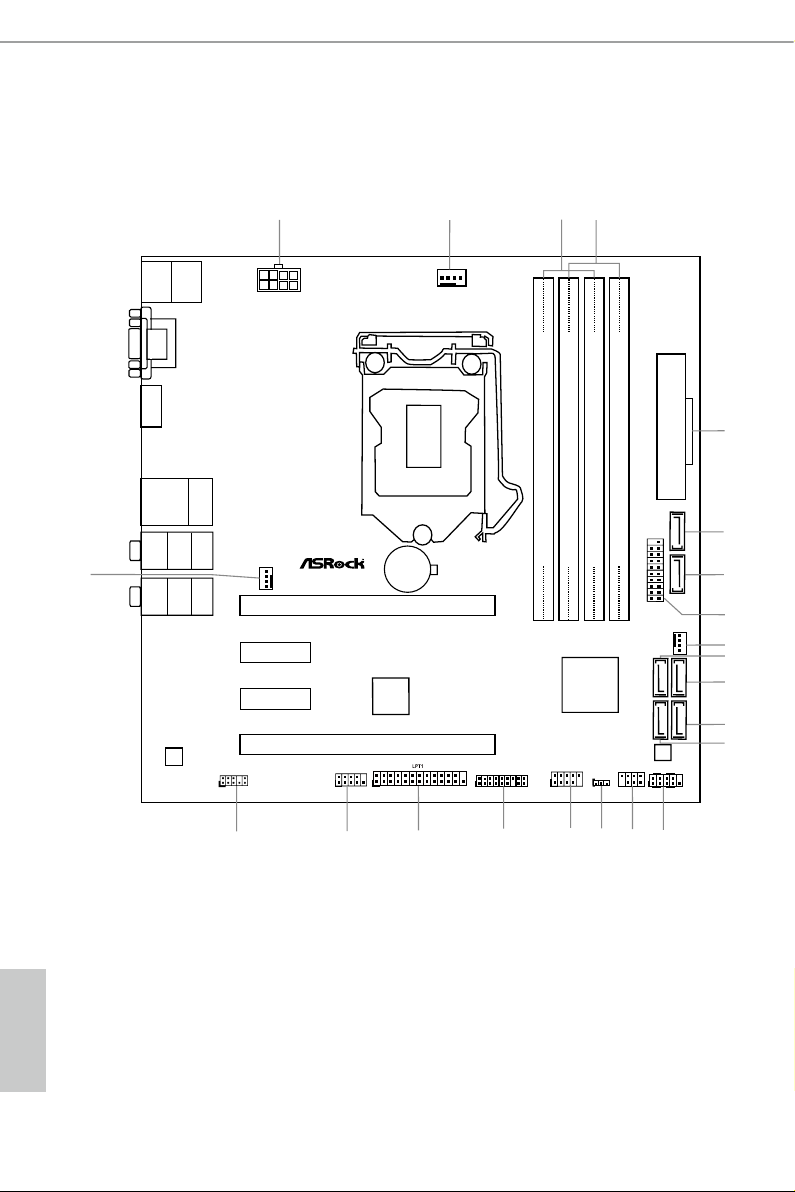
1.3 Motherboard Layout
English
6 7

No. Description
1 ATX 12V Power Connector (ATX12V1)
2 CPU Fan Connector (CPU_FAN1)
3 2 x 288-pin DDR4 DIMM Slots (DDR4_A1, DDR4_B1)
4 2 x 288-pin DDR4 DIMM Slots (DDR4_A2, DDR4_B2)
5 ATX Power Connector (ATXPWR1)
6 SATA3 Connector (SATA3_0)
7 SATA3 Connector (SATA3_1)
8 USB 3.0 Header (USB3_5_6)
9 Chassis Fan Connector (CHA_FAN2)
10 SATA3 Connector (SATA3_2)
11 SATA3 Connector (SATA3_3)
12 SATA3 Connector (SATA3_5)
13 SATA3 Connector (SATA3_4)
14 System Panel Header (PANEL1)
15 Chassis Intrusion and Speaker Header (SPK_CI1)
16 Clear CMOS Jumper (CLRMOS1)
17 USB 2.0 Header (USB1_2)
18 TPM Header (TPMS1)
19 Print Port Header (LPT1)
20 COM Port Header (COM1)
21 Front Panel Audio Header (HD_AUDIO1)
22 Chassis Fan Connector (CHA_FAN1)
B150M Pro4
English

1.4 I/O Panel
1
13 1011 9 812
No. Description No. Description
1 PS/2 Mouse/Keyboard Port 8 Microphone (Pink)
2 D-Sub Port 9 Central / Bass (Orange)
3 LAN RJ-45 Port* 10 USB 3.0 Ports (USB3_34)
4 Side Speaker (Gray) 11 HDMI Port
5 Rear Speaker (Black) 12 DVI-D Por t
6 Line In (Light Blue) 13 USB 3.0 Ports (USB3_12)
7 Front Speaker (Lime)**
2
3 5
4
6
7
English
8 9

B150M Pro4
* ere are two LEDs on each LAN port. Plea se refer to the table below for the LAN port LED indications.
ACT/LINK LED
SPEED LED
LAN Por t
Activity / Link LED Speed LED
Status Description Status Description
O No Link O 10Mbps connection
Blinking Data Activity Orange 100Mbps connection
On Link Green 1Gbps connection
** If you use a 2- channel speaker, please connec t the speaker’s plug into “Front Speaker Jack”. See the table below
for connection details in a ccordance with the t ype of speaker you use.
Audio Output
Channels
Front Speaker
(No. 7)
Rear Speaker
(No. 5)
Central / Bass
(No. 9)
2 V -- -- --
4 V V -- --
6 V V V --
8 V V V V
To enable Multi-Streaming, you need to conn ect a front panel audio cable to the front
panel au dio header. Aer restarting your computer, you will nd the “Mixer” tool
on your system. Please select “Mixe r ToolBox” , click “Enable playback multistreaming”, and click “ok”. Choose “2CH”, “4CH”, “6CH”, or “8CH” and then you are
allowe d to selec t “Realtek HDA Primary out put” to use the Rear Speaker, Central/
Bass, and Front Speaker, or select “Realtek HDA Audio 2nd output” to use the front
panel audio.
Line In
(No. 6)
English

Chapter 2 Installation
is is a Micro ATX form factor motherboard. Before you install the motherboard,
study the conguration of your chassis to ensure that the motherboard ts into it.
Pre-installation Precautions
Take note of the following precautions before you install motherboard components
or change any motherboard settings.
Make sure to unplug the power cord before installing or removing the motherboard
•
components. Failure to do so may cause physical injuries and damages to motherboard
components.
In order to avoid damage from static electricity to the motherboard’s components,
•
NEVER place your motherboard directly on a carpet. Also remember to use a grounded
wrist strap or touch a safety grounded object before you handle the components.
Hold components by the edges and do not touch the ICs.
•
Whenever you uninstall any components, place them on a grounded anti-static pad or
•
in the bag that comes with the components.
When placing screws to secure the motherboard to the chassis, please do not over-
•
tighten the screws! Doing so may damage the motherboard.
English
10 11
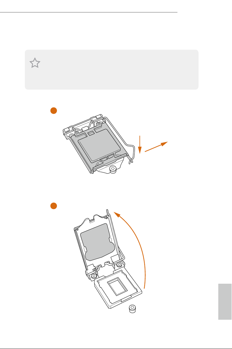
2.1 Installing the CPU
1. Before you insert the 1151-Pin CPU into the socket , please check if the PnP cap is on the
socket, if the CPU sur face is unclean, or if the re are any bent pins in the socket . Do not
force to in sert the CPU into the socket if above situation is found. Otherwise, the CPU
will be seriously damaged.
2. Unplug all power c ables be fore installing the CPU.
1
B150M Pro4
A
B
2
English
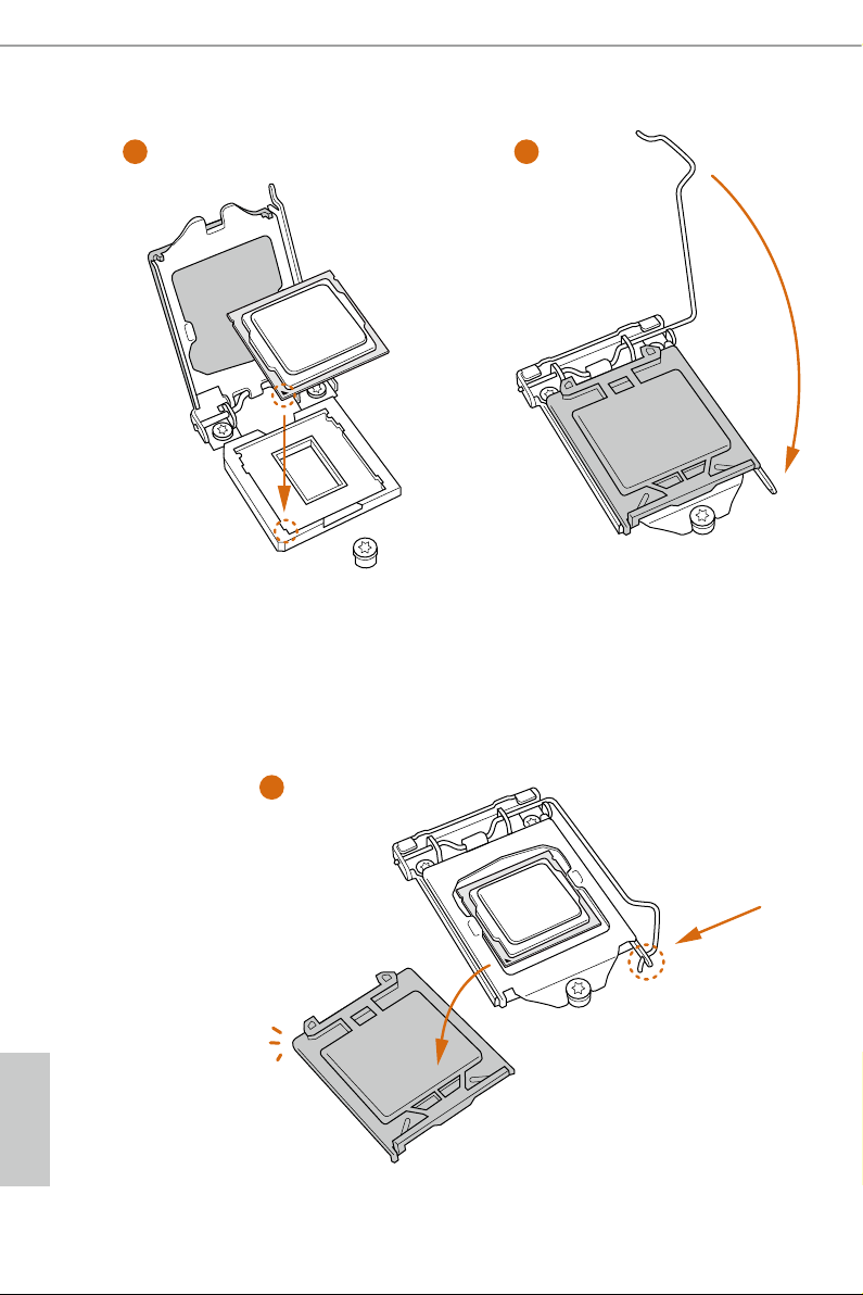
3
4
5
English
12 13

Please save and replace the cover if the processor is removed. e cove r must be placed if
you wish to return the motherboard for ae r service.
B150M Pro4
English
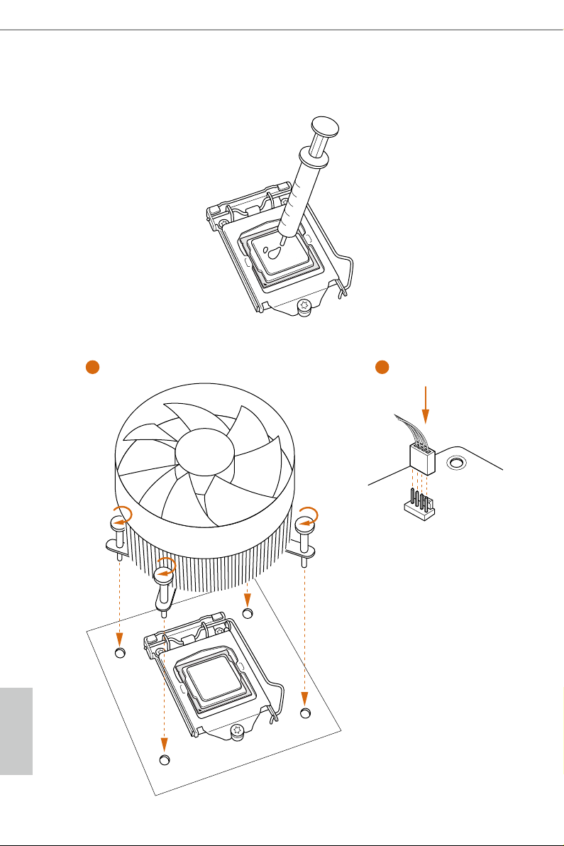
2.2 Installing the CPU Fan and Heatsink
1 2
FAN
CPU_
English
14 15
2.3 Installing Memory Modules (DIMM)
is motherboard provides four 288-pin DDR4 (Double Data Rate 4) DIMM slots,
and supports Dual Channel Memory Technology.
1. For dual channel conguration, you always need to install identical (the same brand,
speed , size and chip-type) DDR4 DIMM pairs.
2. It is unable to activate Dual Channel Me mory Technol ogy with only one or three memory
module installed.
3. It is not allowed to install a DDR, DDR2 or DDR3 memory module into a DDR4 slot;
otherwise, this mothe rboard and DI MM may be damaged.
Dual Channel Memory Conguration
Priority DDR4_A1 DDR4_A2 DDR4_B1 DDR4_B2
1 Populated Populated
2 Populated Populated
3 Populated Populated Populated Populated
B150M Pro4
e DIMM only ts in one correct orientation. It wil l cause permane nt damage to the
motherboard and the DIMM if you force the DIMM into the slot at incorrect orie ntation .
English
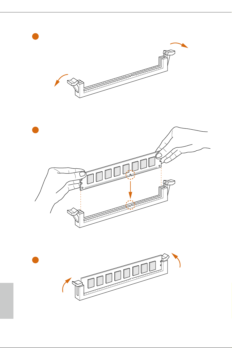
1
2
3
English
16 17
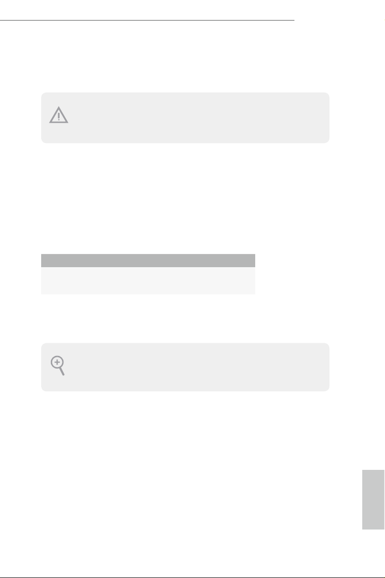
2.4 Expansion Slots (PCI Express Slots)
ere are 4 PCI Express slots on the motherboard.
Before installing an expansion card, plea se make sure that the power supply is
switched o or the power cord is unplugged. Please read the docume ntation of the
expan sion card and mak e necessary hardware settings for the card before you start
the installation.
PCIe slots:
PCIE1 (PCIe 3.0 x16 slot) is used for PCI Express x16 lane width graphics cards.
PCIE2 (PCIe 3.0 x1 slot) is used for PCI Express x1 lane width cards.
PCIE3 (PCIe 3.0 x1 slot) is used for PCI Express x1 lane width cards.
PCIE4 (PCIe 3.0 x16 slot) is used for PCI Express x4 lane width graphics cards.
PCIe Slot Congurations
PCIE1 PCIE4
Single Graphics Card x16 N/A
B150M Pro4
Two Graphics Cards in
CrossFireXTM Mode
For a better thermal environment, please connect a ch assis fan to the moth erboard ’s
chassis fan connector (CHA _FAN1 or CHA_FAN2) when using multiple g raphics
cards.
x16 x4
English
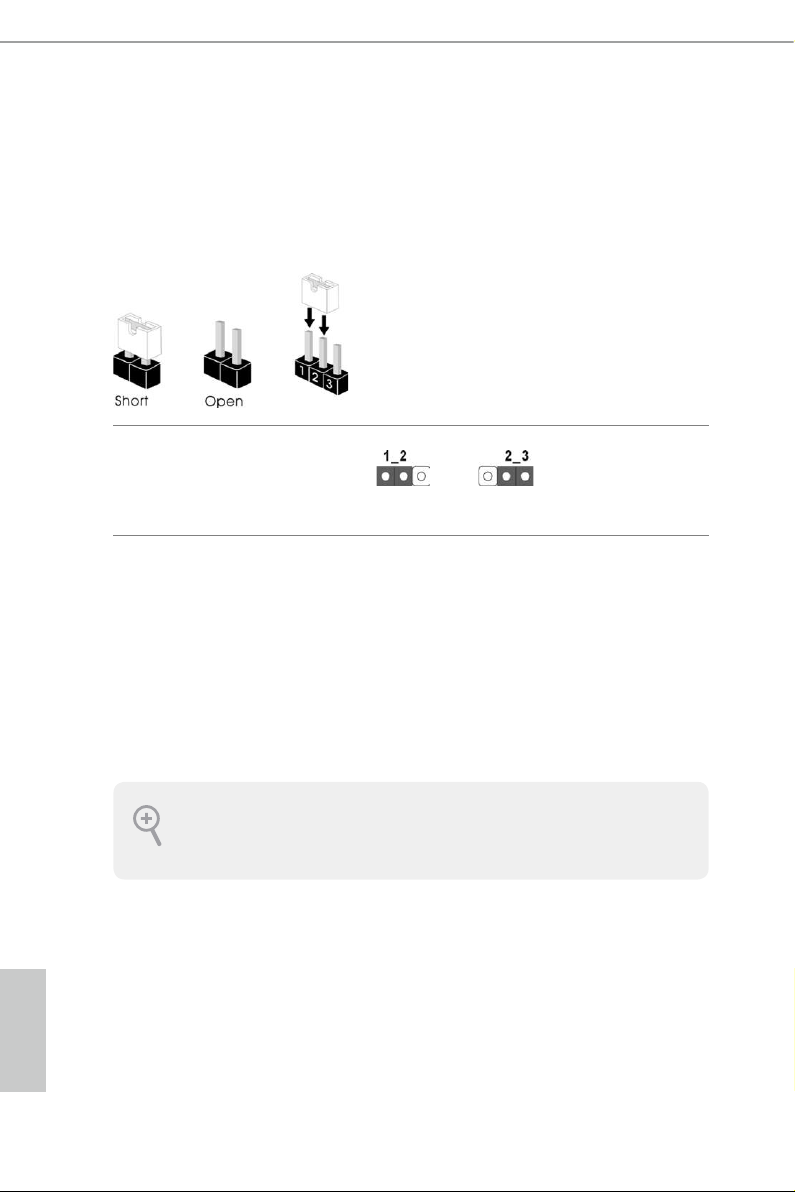
2.5 Jumpers Setup
e illustration shows how jumpers are setup. When the jumper cap is placed on
the pins, the jumper is “Short”. If no jumper cap is placed on the pins, the jumper
is “Open”. e illustration shows a 3-pin jumper whose pin1 and pin2 are “Short”
when a jumper cap is placed on these 2 pins.
Clear CMOS Jumper
(CLR MOS1)
(see p.6, No. 16)
CLRMOS1 allows you to clear the data in CMOS. To clear and reset the system
parameters to default setup, please turn o the computer and unplug the power
cord from the power supply. Aer waiting for 15 seconds, use a jumper cap to
short pin2 and pin3 on CLRMOS1 for 5 seconds. However, please do not clear the
CMOS right aer you update the BIOS. If you need to clear the CMOS when you
just nish updating the BIOS, you must boot up the system rst, and then shut it
down before you do the clear-CMOS action. Please be noted that the password,
date, time, and user default prole will be cleared only if the CMOS batter y is
removed.
Clear CMOSDefault
If you clear the CMOS, the case open may be detected. Please a djust the BIOS option “Cl ear
Status” to clear the record of previous ch assis intrus ion statu s.
English
18 19
 Loading...