

Page 1
Page 2

Version 1.0
Published July 2020
Copyright©2020 ASRock INC. All rights reserved.
Copyright Notice:
No part of this documentation may be reproduced, transcribed, transmitted, or
translated in any language, in any form or by any means, except duplication of
documentation by the purchaser for backup purpose, without written consent of
ASRock Inc.
Products and corporate names appearing in this documentation may or may not
be registered trademarks or copyrights of their respective companies, and are used
only for identication or explanation and to the owners’ benet, without intent to
infringe.
Disclaimer:
Specications and information contained in this documentation are furnished for
informational use only and subject to change without notice, and should not be
constructed as a commitment by ASRock. ASRock assumes no responsibility for
any errors or omissions that may appear in this documentation.
With respect to the contents of this documentation, ASRock does not provide
warranty of any kind, either expressed or implied, including but not limited to
the implied warranties or conditions of merchantability or tness for a particular
purpose.
In no event shall ASRock, its directors, ocers, employees, or agents be liable for
any indirect, special, incidental, or consequential damages (including damages for
loss of prots, loss of business, loss of data, interruption of business and the like),
even if ASRock has been advised of the possibility of such damages arising from any
defect or error in the documentation or product.
is device complies with Part 15 of the FCC Rules. Operation is subject to the following
two conditions:
(1) this device may not cause harmful interference, and
(2) this device must accept any interference received, including interference that
may cause undesired operation.
CALIFORNIA, USA ONLY
e Lithium battery adopted on this motherboard contains Perchlorate, a toxic substance
controlled in Perchlorate Best Management Practices (BMP) regulations passed by the
California Legislature. When you discard the Lithium battery in California, USA, please
follow the related regulations in advance.
“Perchlorate Material-special handling may apply, see ww w.dtsc.ca.gov/hazardouswaste/
perchlorate”
ASRock Website: http://www.asrock.com
Page 3

AUSTRALIA ONLY
Our goods come with guarantees that cannot be excluded under the Australian
Consumer Law. You are entitled to a replacement or refund for a major failure and
compensation for any other reasonably foreseeable loss or damage caused by our
goods. You are also entitled to have the goods repaired or replaced if the goods fail
to be of acceptable quality and the failure does not amount to a major failure. If
you require assistance please call ASRock Tel : +886-2-28965588 ext.123 (Standard
International call charges apply)
e terms HDMI® and HDMI High-Denition Multimedia Interface, and the
HDMI logo are trademarks or registered trademarks of HDMI Licensing LLC in the
United States and other countries.
Page 4
CE Warning
is device complies with directive 2014/53/EU issued by the Commision of the European
Community.
is equipment complies with EU radiation exposure limits set forth for an uncontrolled
environment.
is equipment should be installed and operated with minimum distance 20cm between
the radiator & your body.
Operations in the 5.15-5.35GHz band are restricted to indoor usage only.
Radio transmit power per transceiver type
Function Frequency Maximum Output Power (EIRP)
2400-2483.5 MHz 18.5 + / -1.5 dbm
5150-5250 MHz 21.5 + / -1.5 dbm
WiFi
Bluetooth 2400-2483.5 MHz 8.5 + / -1.5 dbm
5250-5350 MHz
5470-5725 MHz
18.5 + / -1.5 dbm (no TPC)
21.5 + / -1.5 dbm (TPC)
25.5 + / -1.5 dbm (no TPC)
28.5 + / -1.5 dbm (TPC)
Page 5

Contents
Chapter 1 Introduction 1
1.1 Package Contents 1
1.2 Specications 2
1.3 Motherboard Layout 6
1.4 I/O Panel 8
1.5 WiFi-802.11ac Module and ASRock WiFi 2.4/5 GHz
Antennas 10
Chapter 2 Installation 12
2.1 Installing the CPU 13
2.2 Installing the CPU Fan and Heatsink 15
2.3 Installing Memory Modules (DIMM) 23
2.4 Expansion Slots (PCI Express Slots) 25
2.5 Jumpers Setup 26
2.6 Onboard Headers and Connectors 27
2.7 M.2_SSD (NGFF) Module Installation Guide 31
Chapter 3 Software and Utilities Operation 35
3.1 Installing Drivers 35
3.2 ASRock Motherboard Utility (A-Tuning) 36
3.2.1 Installing ASRock Motherboard Utility (A-Tuning) 36
3.2.2 Using ASRock Motherboard Utility (A-Tuning) 36
3.3 ASRock Live Update & APP Shop 39
Page 6

3.3.1 UI Overview 39
3.3.2 Apps 40
3.3.3 BIOS & Drivers 43
3.3.4 Setting 44
Chapter 4 UEFI SETUP UTILITY 45
4.1 Introduction 45
4.1.1 UEFI Menu Bar 45
4.1.2 Navigation Keys 46
4.2 Main Screen 47
4.3 OC Tweaker Screen 48
4.4 Advanced Screen 51
4.4.1 CPU Conguration 52
4.4.2 Onboard Devices Conguration 53
4.4.3 Storage Conguration 55
4.4.4 ACPI Conguration 56
4.4.5 Super IO Conguration 57
4.4.6 Trusted Computing 58
4.4.7 AMD PBS 59
4.4.8 AMD Overclocking 60
4.4.9 AMD CBS 61
4.5 Tools 62
4.6 Hardware Health Event Monitoring Screen 63
4.7 Security Screen 65
4.8 Boot Screen 66
Page 7
Chapter 1 Introduction
ank you for purchasing ASRock A520M/ac motherboard, a reliable motherboard
produced under ASRock ’s consistently stringent quality control. It delivers excellent
performance with robust design conforming to ASRock ’s commitment to quality
and endurance.
In this documentation, Chapter 1 and 2 contains the introduction of the
motherboard and step-by-step installation guides. Chapter 3 contains the operation
guide of the soware and utilities. Chapter 4 contains the conguration guide of
the BIOS setup.
Becau se the motherboard specications and the BIOS soware might be updated, the
content of this documentation will be subject to change without notice. In case any modications of this documentation occur, the updated version will be available on ASRock’s
website w ithout further notice. If you require technical support related to this motherboard, please visit our website for specic information about the model you are using. You
may nd the l atest VGA cards and CPU suppor t list on ASRock’s website a s well. ASRock
website http://www.asrock.com.
A520M/ac
1.1 Package Contents
ASRock A520M/ac Motherboard (Micro ATX Form Factor)
•
ASRock A520M/ac Quick Installation Guide
•
1 x I/O Panel Shield
•
2 x Serial ATA (SATA) Data Cables (Optional)
•
2 x ASRock WiFi 2.4/5 GHz Antennas (O pt iona l)
•
1 x Screw for M.2 Socket (Optional)
•
English
1
Page 8

1.2 Specications
Platform
CPU
Chipset
Memory
•
•
•
* Not compatible with AMD Ryzen™ 5 3400G and Ryzen™ 3
3200G.
•
•
•
•
•
•
* Please refer to Memory Support List on ASRock’s website for
more information. (http://www.asrock.com/)
* Please refer to page 21 for DDR4 UDIMM maximum
frequency support.
•
•
•
Micro ATX Form Factor
Solid Capacitor design
Supports 3rd Gen AMD AM4 Ryzen™ / future AMD Ryzen™
Processors (3000 and 4000 Series Processors)*
6 Power Phase design
AMD A520
Dual Channel DDR4 Memory Technology
2 x DDR4 DIMM Slots
AMD Ryzen series CPUs (Matisse) support DDR4
4600+(OC)/4533(OC)/4466(OC)/4400(OC)/4333
(OC)/4333(OC)/4266(OC)/4200(OC)/4133(OC)/4000
(OC)/3866(OC)/3800(OC)/3733(OC)/3600(OC)/3466|
(OC)/3200/2933/2667/2400/2133 ECC & non-ECC, un-
buered memory*
AMD Ryzen series APUs (Renoir) support DDR4 4733+
(OC)/4666(OC)/4600(OC)/4533(OC)/4466(OC)/4400(OC)/
4333(OC)/4266(OC)/4200(OC)/4133(OC)/4000(OC)/3866
(OC)/3800(OC)/3733(OC)/3600(OC)/3466(OC)/3200/2933/
2667/2400/2133 ECC & non-ECC, un-buered memory*
Max. capacity of system memory: 64GB
Supports Extreme Memory Prole (XMP) memory modules
15μ Gold Contact in DIMM Slots
English
2
Expansion
Slot
1 x PCI Express 3.0 x16 Slot (PCIE2: x16 mode)*
•
* Supports NVMe SSD as boot disks
1 x PCI Express 3.0 x1 Slot
•
1 x Vertical M.2 Socket (Key E) with the bundled WiFi-
•
802.11ac module (on the rear I/O)
Page 9

Graphics
Audio
Integrated AMD RadeonTM Vega Series Graphics in Ryzen
•
Series APU*
* Actual support may vary by CPU
DirectX 12, Pixel Shader 5.0
•
Shared memor y default 2GB. Max Shared memory supports
•
up to 16GB.
* e Max shared memory 16GB requires 32GB system
memory installed.
Supports HDMI 2.1 with max. resolution up to 4K x 2K
•
(4096x2160) @ 60Hz
Supports Auto Lip Sync, Deep Color (12bpc), xvYCC and
•
HBR (High Bit Rate Audio) with HDMI 2.1 Port (Compliant
HDMI monitor is required)
Supports HDR (High Dynamic Range) with HDMI 2.1
•
Supports HDCP 2.3 with HDMI 2.1 Port
•
Supports 4K Ultra HD (UHD) playback with HDMI 2.1
•
Port
Supports Microso PlayReady®
•
7.1 CH HD Audio (Realtek ALC887 Audio Codec)
•
Supports Surge Protection
•
A520M/ac
LAN
Wireless
LAN
PCIE x1 Gigabit LAN 10/100/1000 Mb/s
•
Realtek RTL8111H
•
Supports Wake-On-LAN
•
Supports Lightning/ESD Protection
•
Supports Energy Ecient Ethernet 802.3az
•
Supports PXE
•
Intel® 802.11ac WiFi Module
•
Supports IEEE 802.11a/b/g/n/ac
•
Supports Dual-Band (2.4/5 GHz)
•
Supports high speed wireless connections up to 433Mbps
•
Supports Bluetooth 4.2 / 3.0 + High speed class II
•
English
3
Page 10

Rear Panel
I/O
Storage
Connector
2 x Antenna Ports
•
1 x PS/2 Mouse/Keyboard Port
•
1 x HDMI Port
•
2 x USB 2.0 Ports (Supports ESD Protection)
•
4 x USB 3.2 Gen1 Ports (Supports ESD Protection)
•
1 x RJ-45 LAN Port with LED (ACT/LINK LED and SPEED
•
LED)
HD Audio Jacks: Line in / Front Speaker / Microphone
•
4 x SATA3 6.0 Gb/s Connectors, support RAID (RAID 0,
•
RAID 1 and RAID 10), NCQ, AHCI and Hot Plug
1 x Ultra M.2 Socket, supports M Key type 2242/2260/2280
•
M.2 SATA3 6.0 Gb/s module and M.2 PCI Express module
up to Gen3 x4 (32 Gb/s)*
* Supports NVMe SSD as boot disks
* Supports ASRock U.2 Kit
1 x SPI TPM Header
•
1 x COM Port Header
•
1 x Chassis Intrusion and Speaker Header
•
1 x CPU Fan Connector (4-pin)
•
* e CPU Fan Connector supports the CPU fan of maximum
1A (12W) fan power.
2 x Chassis Fan Connectors (4-pin) (Smart Fan Speed
•
Control)
* e Chassis Fan supports the water cooler fan of maximum
1A (12W) fan power.
* CHA_FAN2 can auto detect if 3-pin or 4-pin fan is in use.
1 x 24 pin ATX Power Connector
•
1 x 4 pin 12V Power Connector
•
1 x Front Panel Audio Connector
•
2 x USB 2.0 Headers (Support 4 USB 2.0 ports) (Supports
•
ESD Protection)
1 x USB 3.2 Gen1 Header (Supports 2 USB 3.2 Gen1 ports)
•
(Supports ESD Protection)
English
4
Page 11
BIOS
Feature
Hardware
Monitor
OS
Certications
AMI UEFI Legal BIOS with GUI support
•
Supports “Plug and Play”
•
ACPI 5.1 compliance wake up events
•
Supports jumperfree
•
SMBIOS 2.3 support
•
CPU, CPU VDDCR_SOC, DRAM, VDDP Voltage Multi-
•
adjustment
Temperature Sensing: CPU, Chassis Fans
•
Fan Tachometer: CPU, Chassis Fans
•
Quiet Fan (Auto adjust chassis fan speed by CPU
•
temperature): CPU, Chassis Fans
Fan Multi-Speed Control: CPU, Chassis Fans
•
CASE OPEN detection
•
Voltage monitoring: +12V, +5V, +3.3V, CPU Vcore
•
Microso® Windows® 10 64-bit
•
FCC, CE
•
ErP/EuP ready (ErP/EuP ready power supply is required)
•
A520M/ac
* For detailed product information, please visit our website: http://www.asrock .com
Please realiz e that the re is a certain r isk involved with o verclocking, including adjusting
the setting in the BIOS, applying Untied Overclocking Technolog y, or using third-party
overclocking to ols. O verclocking may aect your system’s stability, or even c ause damage to
the components and devices of your system. It should be don e at your ow n risk and expense.
We are not responsibl e for possible damage caused by overclo cking.
English
5
Page 12
ATXPW R1
FS B80 0
DDR 4_A1 (6 4 bit, 28 8-pin m odule )
DDR 4_A2 (6 4 bit, 28 8-pin m odule )
Supe r
I/O
LAN
AUDIO
CODEC
PCIE2
PCIE1
HD_AUDIO1
1
CPU_FAN1
1
COM1
3
4
2
5
USB 2.0
T: USB1
B: USB2
PS2
Keyboard/
Mouse
CMOS
Battery
1
USB3_5 _6
1
CHA_FAN2
HDLED RESET
PLED PWRBTN
PANEL1
1
SPK_CI1
1
USB 3.2 Gen1
T: USB1
B: USB2
Top:
LINE I N
Cent er:
FRON T
Bott om:
MIC IN
RJ- 45 LAN
USB 3.2 Gen1
T: USB3
B: USB4
ATX12V
SOCKETAM4
CHA_FAN1
M2_ 1
USB_5_61USB_3_4
1
RoHS
1
SPI_TPM_J1
HDM I1
CLRCMOS1
1
Ultra M.2
PCIe Gen3x4
15
10
981314 12 11
17
16
6
7
SATA3_3
SATA3_4
SATA3_1
SATA3_2
M2_WIFI_1
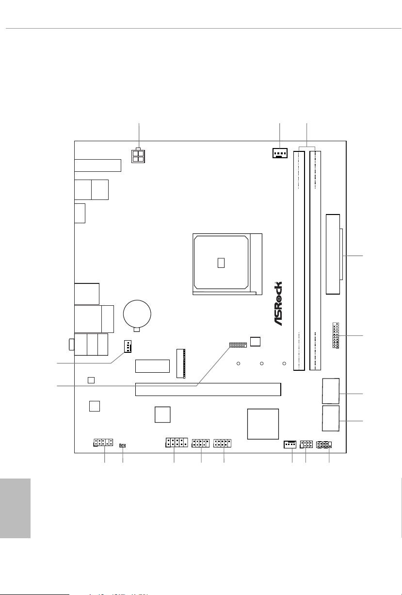
1.3 Motherboard Layout
English
A5 2 0 M / a c
BIOS
ROM
AMD
Promontory
A520
6
Page 13

No. Description
1 ATX 12V Power Connector (ATX12V1)
2 CPU Fan Connector (CPU_FAN1)
3 2 x 288-pin DDR4 DIMM Slots (DDR4_A1, DDR4_B1)
4 ATX Power Connector (ATXPWR1)
5 USB 3.2 Gen1 Header (USB3_ 5_6)
6 SATA3 Connector (SATA3_3) (Upper), SATA3 Connector (SATA3_4) (Lower)
7 SATA3 Connector (SATA3_4) (Upper), SATA3 Connector (SATA3_2) (Lower)
8 System Panel Header (PANEL1)
9 Chassis Intrusion and Speaker Header (SPK_CI1)
10 Chassis Fan Connector (CHA_FAN2)
11 USB 2.0 Header (USB_3_4)
12 USB 2.0 Header (USB_5_6)
13 COM Port Header (COM1)
14 Clear CMOS Jumper (CLRCMOS1)
15 Front Panel Audio Header (HD_AUDIO1)
16 SPI TPM Header (SPI_TPM_J1)
17 Chassis Fan Connector (CHA_FAN1)
A520M/ac
English
7
Page 14
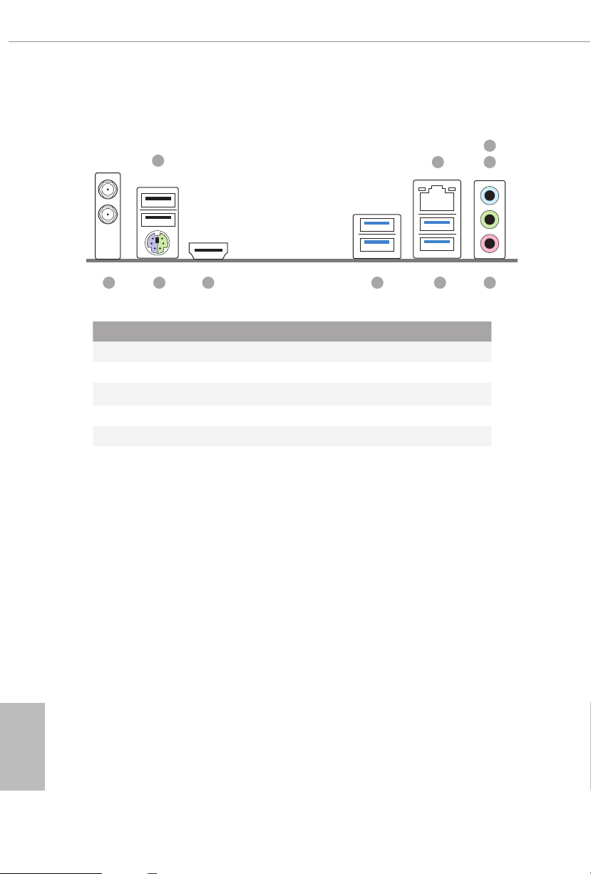
1.4 I/O Panel
1
3
2
4
8 56910
7
No. Description No. Description
1 USB 2.0 Ports (USB_12) 6 USB 3.2 Gen1 Ports (USB3_34)
2 LAN RJ-45 Port* 7 USB 3.2 Gen1 Ports (USB3_12)
3 Line In (Light Blue)** 8 HDMI Port***
4 Front Speaker (Lime)** 9 PS/2 Mouse/Keyboard Port
5 Microphone (Pink)** 10 Antenna Ports
English
8
Page 15
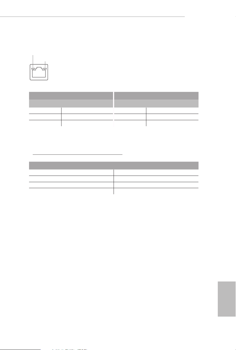
* ere are two LEDs on each LAN port. Please refer to the table below for the LAN port LED indications.
ACT/LINK LED
SPEED LED
LAN Por t
Activity / Link LED Speed LED
Status Description Status Description
O No Link O 10Mbps connection
Blinking Data Activity Orange 100Mbps connection
On Link Green 1Gbps connection
** Function of the Audio Ports in 7.1-channel Conguration:
Port Function
Light Blue (Rear panel) Rear Speaker Out
Lime (Rear panel) Front Speaker Out
Pink (Rear panel) Central /Subwoofer Speaker Out
Lime (Front panel) Side Speaker Out
A520M/ac
*** Please note that u sing a HDMI to DVI adapter cable may aect the stability of 5G network connection.
English
9
Page 16

1.5 WiFi-802.11ac Module and ASRock WiFi 2.4/5 GHz
Antennas
WiFi-802.11ac + BT Module
is motherboard comes with an exclusive WiFi 802.11 a/b/g/n/ac + BT v4.2
module (pre-installed on the rear I/O panel) that oers support for WiFi 802.11 a/b/
g/n/ac connectivity standards and Bluetooth v4.2. WiFi + BT module is an easy-to-
use wireless local area network (WLAN) adapter to support WiFi + BT. Bluetooth
v4.2 standard features Smart Ready technology that adds a whole new class of
functionality into the mobile devices. BT 4.2 also includes Low Energy Technolog y
and ensures extraordinary low power consumption for PCs.
* e transmission speed may vary according to the environment.
English
10
Page 17
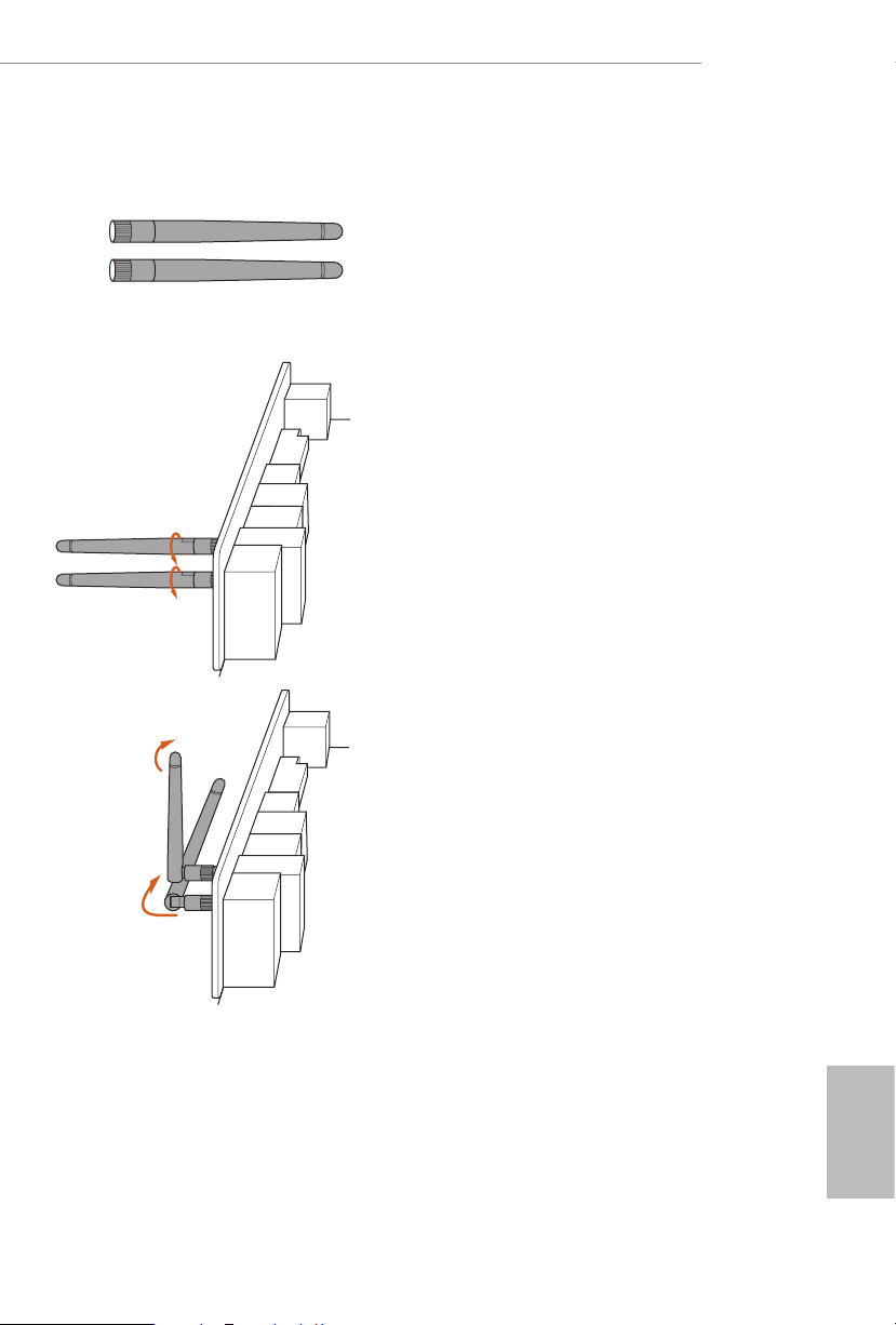
WiFi Antennas Installation Guide
A520M/ac
Step 1
Prepare the WiFi 2.4/5 GHz Antennas that come
with the package.
Step 2
Connect the two WiFi 2.4/5 GHz Antennas to
the antenna connectors. Turn the antenna clock-
wise until it is securely connected.
Step 3
Set the WiFi 2.4/5 GHz Antenna as shown in the
illustration.
*You may need to adjust the direction of
the antenna for a stronger signal.
English
11
Page 18

Chapter 2 Installation
is is a Micro ATX form factor motherboard. Before you install the motherboard,
study the conguration of your chassis to ensure that the motherboard ts into it.
Pre-installation Precautions
Take note of the following precautions before you install motherboard components
or change any motherboard settings.
Make sure to unplug the power cord before installing or removing the motherboard.
•
Failure to do so may cause physical injuries to you and damages to motherboard
components.
In order to avoid damage from static electricity to the motherboard’s components,
•
NEVER place your motherboard directly on a carpet. Also remember to use a grounded
wrist strap or touch a safety grounded object before you handle the components.
Hold components by the edges and do not touch the ICs.
•
Whenever you uninstall any components, place them on a grounded anti-static pad or
•
in the bag that comes with the components.
When placing screws to secure the motherboard to the chassis, please do not over-
•
tighten the screws! Doing so may damage the motherboard.
English
12
Page 19
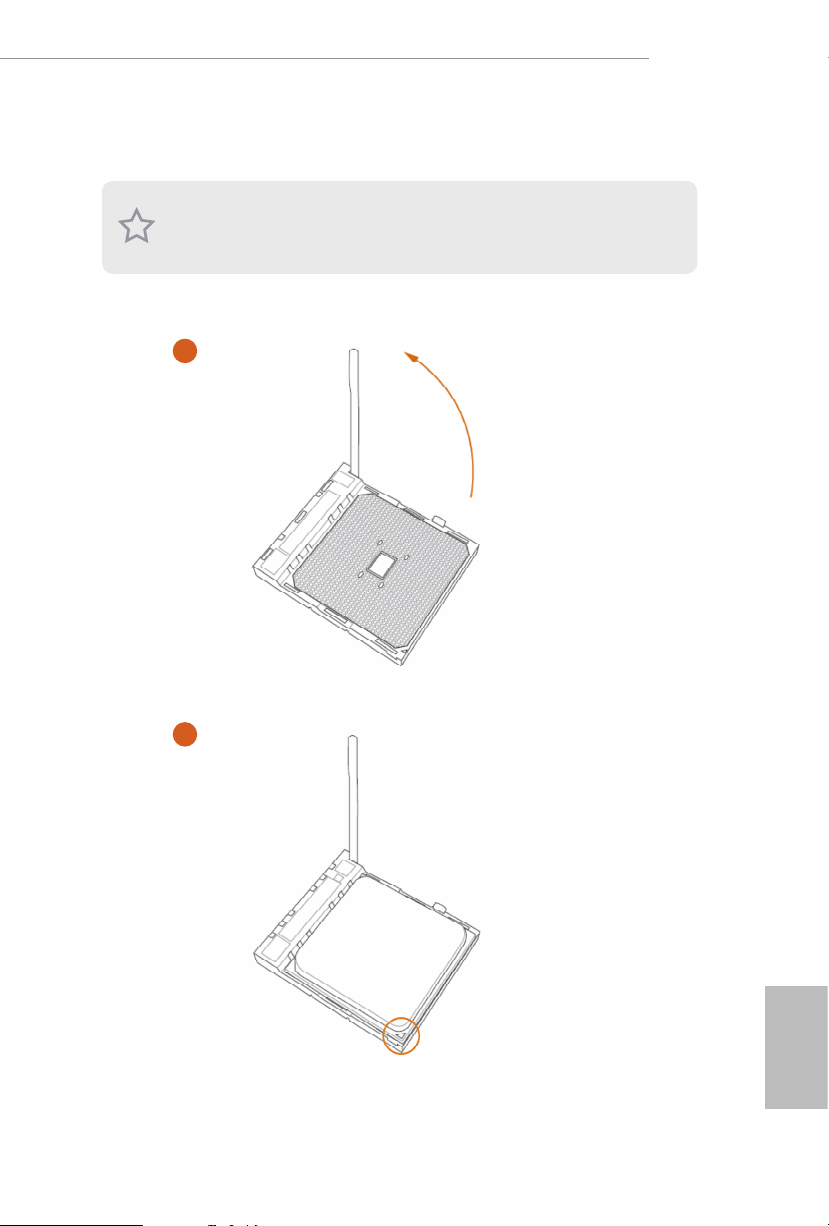
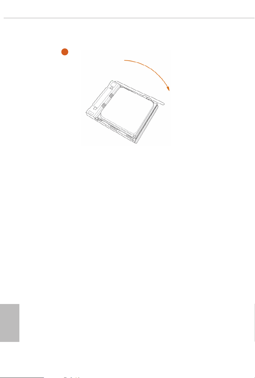
2.1 Installing the CPU
Unplug all power cables be fore installing the CPU.
1
A520M/ac
2
English
13
Page 20
3
English
14
Page 21
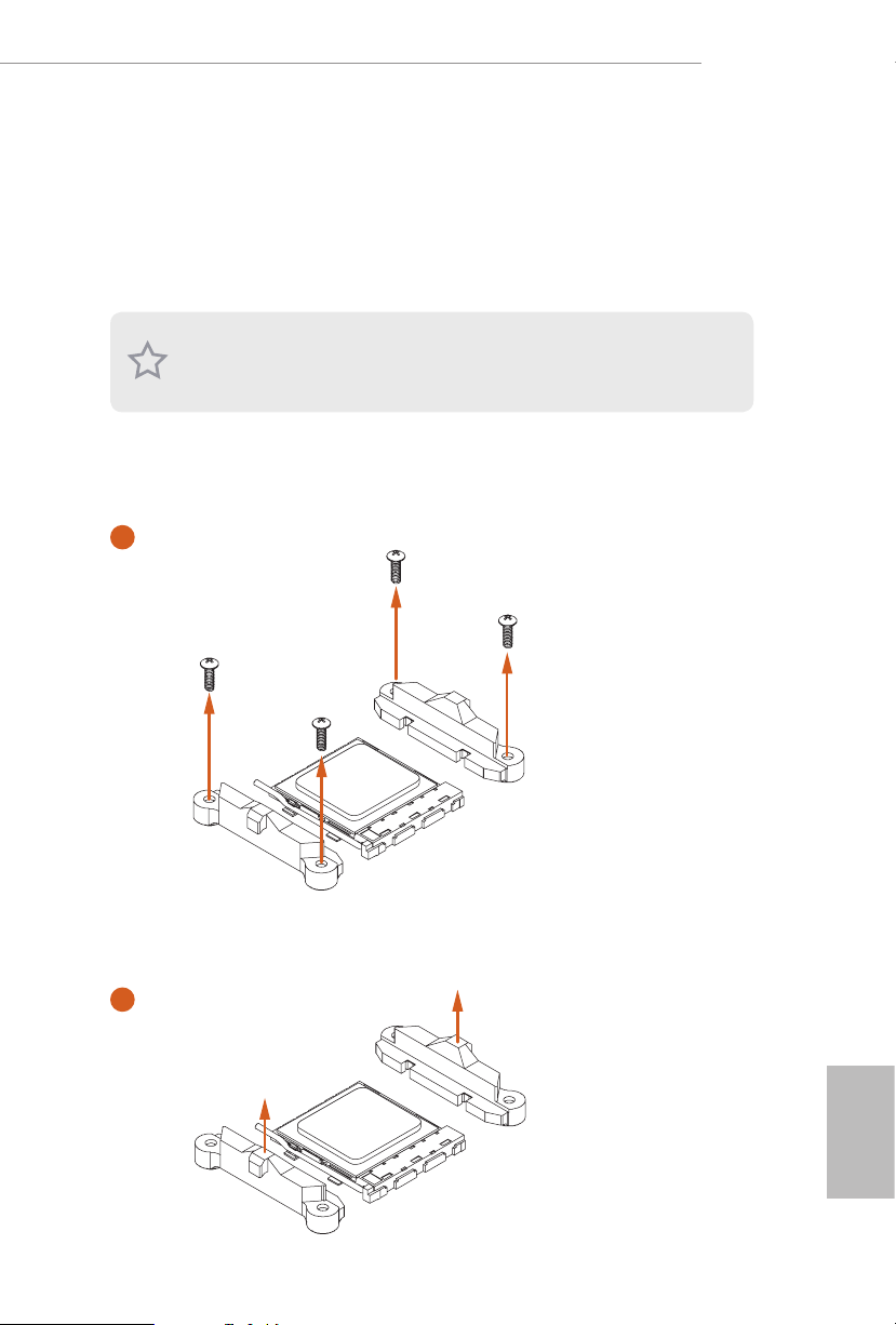
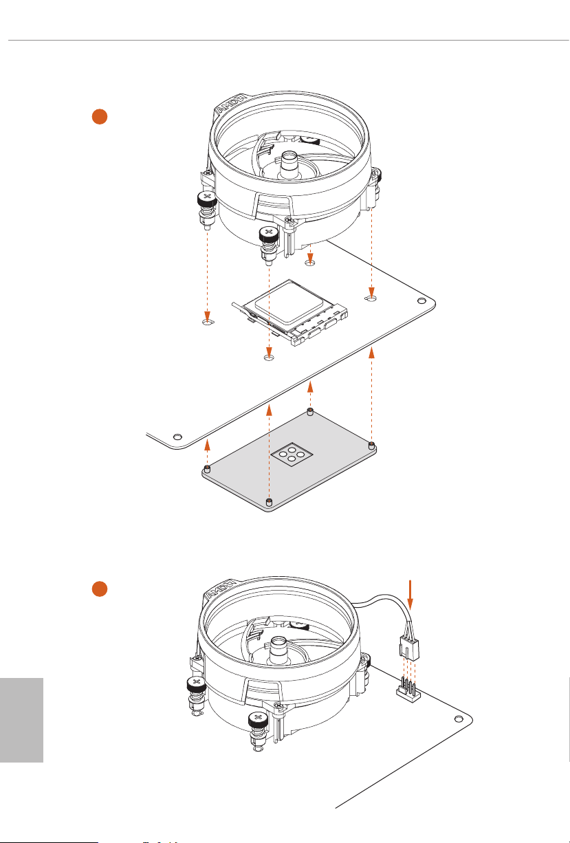
2.2 Installing the CPU Fan and Heatsink
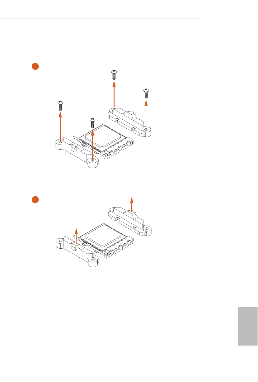
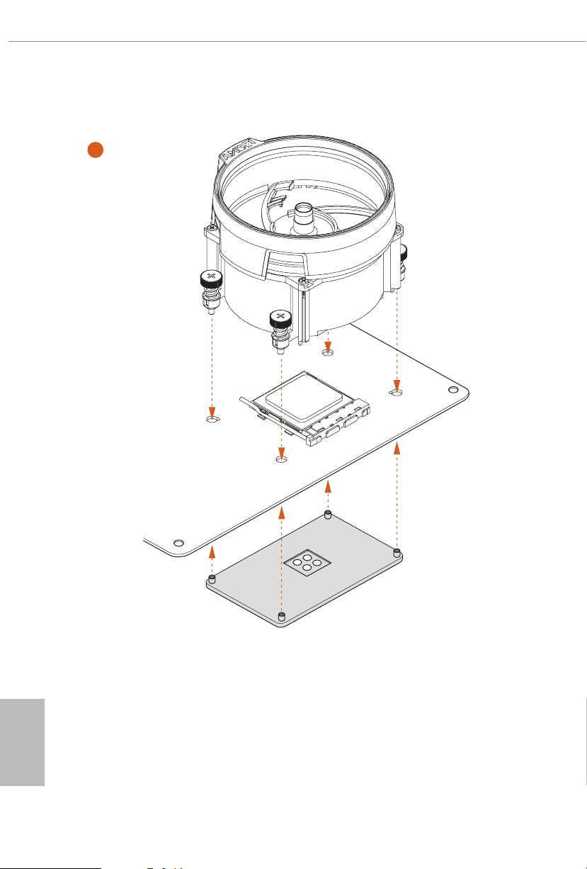
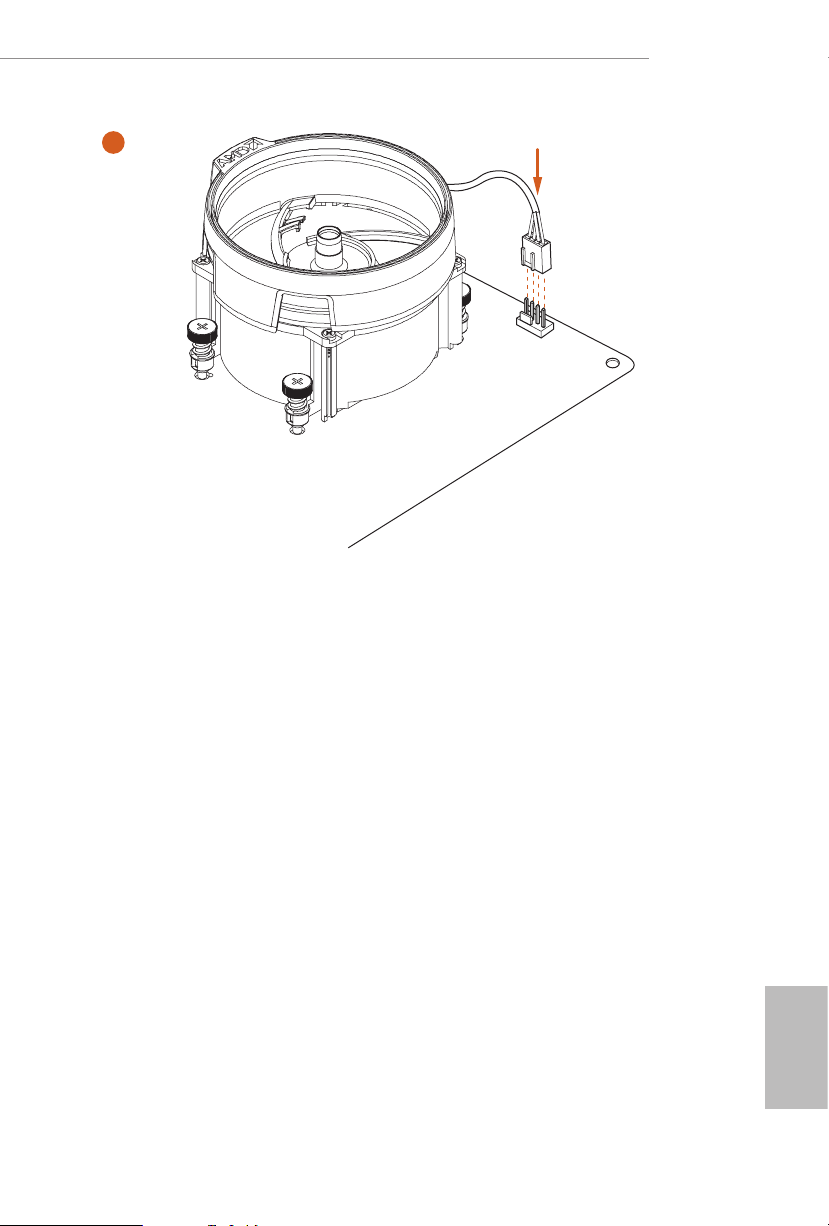
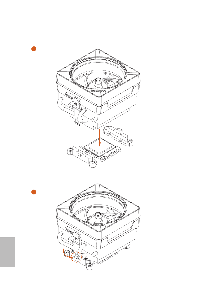
Aer you install the CPU into this motherboard, it is necessary to install a larger
heatsink and cooling fan to dissipate heat. You also need to spray thermal grease
between the CPU and the heatsink to improve heat dissipation. Make sure that the
CPU and the heatsink are securely fastened and in good contact with each other.
Please turn o the power or remove th e power cord before changing a CPU or heatsink.
Installing the CPU Box Cooler SR1
1
A520M/ac
2
English
15
Page 22
3
English
16
4
1
N
FA
_
U
P
C
Page 23
Installing the AM4 Box Cooler SR2
1
A520M/ac
2
English
17
Page 24
3
English
18
Page 25
A520M/ac
4
1
N
FA
_
U
P
C
*e diagrams shown here are for reference only. e headers might be in a dierent position on
your motherboard.
19
English
Page 26
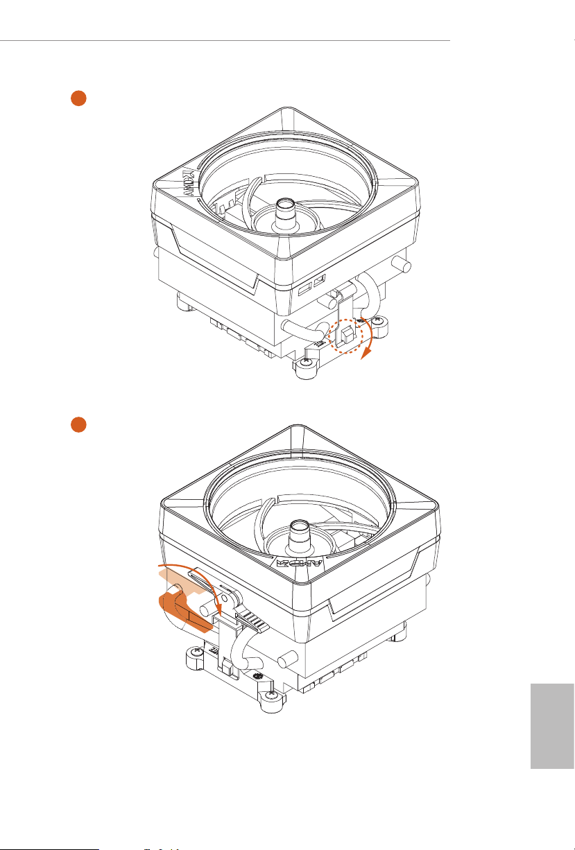
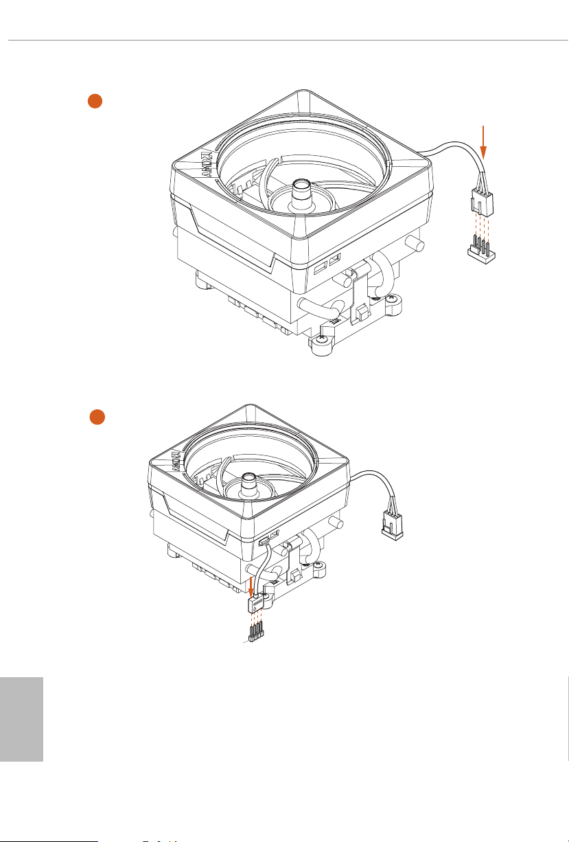
Installing the AM4 Box Cooler SR3
1
English
20
2
Page 27
A520M/ac
4
3
English
21
Page 28
5
FAN1
CPU_
6
English
22
1
N
FA
_
U
P
C
2
D
E
L
_
B
RG
+12V
*e diagrams shown here are for reference only. e headers might be in a dierent position
on your motherboard.
Page 29

2.3 Installing Memory Modules (DIMM)
is motherboard provides two 288-pin DDR4 (Double Data Rate 4) DIMM slots,
and supports Dual Channel Memory Technology.
1. For dual channel cong uration , you always need to in stall identical (the same
brand, speed , size and chip-type) DDR4 DIMM pairs.
2. It is unable to activate Du al Channel Memory Technology with only one memory
module installed.
3. It is not allowed to install a DDR, DDR2 or DDR3 memory module into a DDR4
slot; otherwise, this motherboard and DIMM may be damaged.
AMD non-XMP Memory Frequency Support
Ryzen Series CPUs (Matisse):
A520M/ac
UDIMM Memory Slot
A1 B1
SR - 3200
- SR 3200
DR - 3200
- DR 3200
SR SR 3200
DR DR 3200
Ryzen Series APUs (Renoir):
UDIMM Memory Slot
A1 B1
SR - 3200
- SR 3200
DR - 3200
- DR 3200
SR SR 3200
DR DR 3200
Frequency
(Mhz)
Frequency
(Mhz)
English
23
Page 30
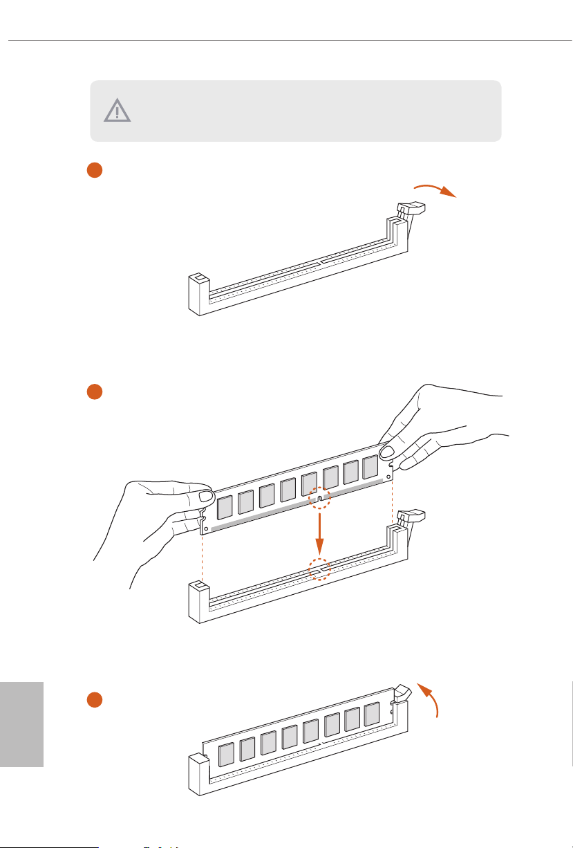
e DIMM only ts in one correct orie ntation. It will cause permanent dam age to
the motherboard and the DIMM if you force the DIMM into the slot at incor rect
orientation.
1
2
English
24
3
Page 31
2.4 Expansion Slots (PCI Express Slots)
ere are 2 PCI Express slots on the motherboard.
Before installing an ex pansion card, please make sure that the power supply is
switched o or the power cord is unplugged. Plea se read the documentation of the
expan sion card and mak e necessary h ardware settings for the card before you start
the installation.
PCIe slots:
PCIE1 (PCIe 3.0 x1 slot) is used for PCI Express x1 lane width cards.
PCIE2 (PCIe 3.0 x16 slot) is used for PCI Express x16 lane width graphics cards.
For a better ther mal environme nt, ple ase connect a ch assis fan to the motherboard’s
chassis fan connector (CHA_ FA N1 or CHA_ FAN2 ) when u sing multiple graphics cards.
A520M/ac
25
English
Page 32

2.5 Jumpers Setup
e illustration shows how jumpers are setup. When the jumper cap is placed on
the pins, the jumper is “Short”. If no jumper cap is placed on the pins, the jumper is
“Open”.
English
Clear CMOS Jumper
(CLRMO S1)
(see p.6 or 7, No. 14)
CLRMOS1 allows you to clear the data in CMOS. To clear and reset the system
parameters to default setup, please turn o the computer and unplug the power
cord from the power supply. Aer waiting for 15 seconds, use a jumper cap to
short the pins on CLR MOS1 for 5 seconds. However, please do not clear the
CMOS right aer you update the BIOS. If you need to clear the CMOS when you
just nish updating the BIOS, you must boot up the system rst, and then shut it
down before you do the clear-CMOS action. Please be noted that the password,
date, time, and user default prole will be cleared only if the CMOS battery is
removed. Please remember toremove the jumper cap aer clearing the CMOS.
If you clear the CMOS, the case open may be detected. Pl ease adjust the BIOS option
“Clear Status” to clear the record of previou s chassis int rusion status.
2-pin Jumper
Short: Clear CMOS
Open: Default
26
Page 33
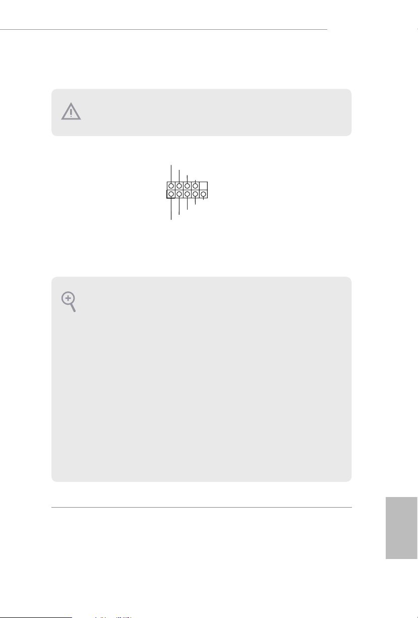
2.6 Onboard Headers and Connectors
PLED+
1
Onboard headers and connectors are NOT jump ers. Do NOT place jumper caps over
these headers and connectors. Placing jumper caps over the headers and connectors
will cause permanent damage to the motherboard.
A520M/ac
System Panel Header
(9-pi n PANEL1)
(see p.6 or 7, No. 8)
PWRBTN (Power Switch):
Connec t to the power switch on the ch assi s front panel. You may congure the way to
turn o your system using the power switch.
RESET (Reset Switch):
Connec t to the reset switch on the chassi s front panel. Press the reset sw itch to restart
the computer if the compute r freezes and fails to perform a norm al restart.
PLED (Syste m Power LED):
Connec t to the power status indicator on the chas sis front panel. e LED i s on when
the system is ope rating. e LED keeps blinking when the system i s in S3 sleep state.
e LED is o when the system i s in S4 sle ep state or powered o (S5).
HDLED (Ha rd Drive Activity LED):
Connec t to the hard drive ac tivity LED on the chassis front panel. e LED is on when
the hard dr ive is reading or w riting data.
e front panel de sign may dier by chassis. A front panel module mainly consists of
power switch, reset sw itch, power LED, hard drive activity LED, speake r and etc. When
connec ting your chassis front panel module to this header, make sure the wire assignments and the pin a ssignments are matche d corre ctly.
PLED-
HDLED-
HDLED+
PWRBTN#
GND
RESET#
GND
GND
Connect the power
switch, reset switch and
system status indicator on
the chassis to this header
according to the pin
assignments below. Note
the positive and negative
pins before connecting
the cables.
English
27
Page 34
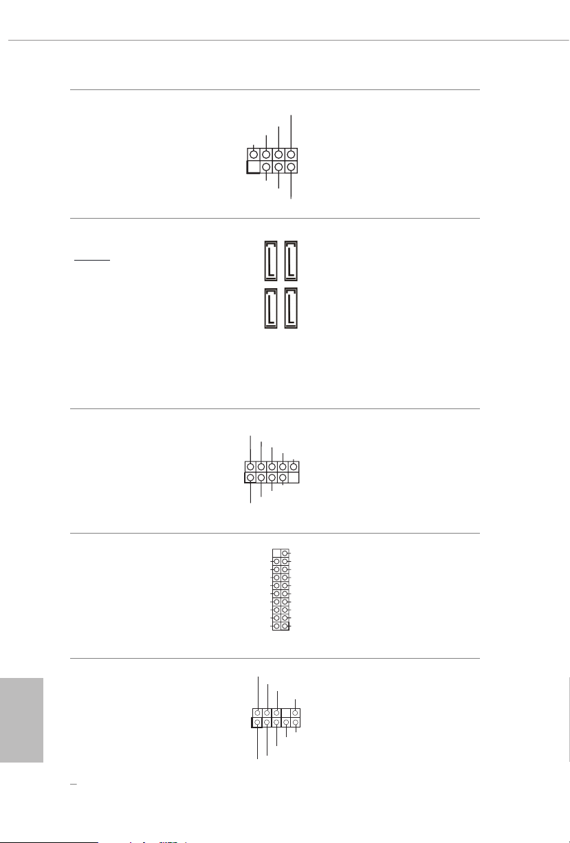
Chassis Intrusion and
1
+5V
DUMMY
SIGNAL
GND
DUMMY
SPEAKER
DUMMY
DUMMY
GND
GND
P+
P-
USB_PWR
P+
P-
USB_PWR
1
1
J_SENSE
OUT2_L
1
MIC_RET
PRESENCE#
GND
OUT2_R
MIC2_R
MIC2_L
OUT_RET
Speaker Header
(7-pi n SPK _CI1)
(see p.6 or 7, No. 9)
Please connect the
chassis intrusion and the
chassis speaker to this
header.
Serial ATA3 Connectors
Ver ti c a l:
(SATA3_1:
see p.6 or 7, No. 7) (Upper)
(SATA3_ 2:
see p.6 or 7, No. 7) (Lower)
(SATA3_ 3:
see p.6 or 7, No. 6) (Upper)
(SATA3_4:
see p.6 or 7, No. 6) (Lower)
USB 2.0 Headers
(9-pin USB_3_4)
(see p.6 or 7, No. 11)
(9-pin USB_5_6)
(see p.6 or 7, No. 12)
USB 3.2 Gen1 Header
(19-pin USB3_5_6)
(see p.6 or 7, No. 5)
SATA3_3
SATA3_1
Vbus
IntA_PA_SSRX-
IntA_PA_SSRX+
GND
IntA_PA_SSTX-
IntA_PA_SSTX+
GND
IntA_PA_D-
IntA_PA_D+
ese four SATA3
connectors support SATA
data cables for internal
SATA3_4
storage devices with up to
6.0 Gb/s data transfer rate.
SATA3_2
ere are two headers
on this motherboard.
Each USB 2.0 header can
support two ports.
VbusVbus
ere is one header on
IntA_PB_SSRX-
IntA_PB_SSRX+
this motherboard. is
GND
IntA_PB_SSTX-
USB 3.2 Gen1 header can
IntA_PB_SSTX+
GND
support two ports.
IntA_PB_D-
IntA_PB_D+
Dummy
English
Front Panel Audio Header
(9-pin HD_ AUDIO1)
(see p.6 or 7, No. 15)
28
is header is for
connecting audio devices
to the front audio panel.
Page 35
1. High Denition Audio support s Jack Sensing, but the panel wire on the cha ssis must
GND
4 3 2 1
FAN_SPEED_CONTROL
4
FAN_SPEED_CONTROL
1 2 3 4
suppor t HDA to function correctly. Please follow the instructions in our manual and
chassis manual to install your system.
2. If you use an AC’97 audio panel , please install it to th e front panel audio header by
the steps below:
A. Connect Mic_IN (MIC) to MIC2_ L.
B. Conne ct Audio_R (RIN) to OUT2_R and Audio_ L (LIN) to OUT2_ L.
C. Connect Ground (GND) to Ground (GND).
D. MIC_ RET and OUT_RET are for the HD audio panel only. You don’t need to connect them for the AC’97 audio panel.
E. To activate the front mic, go to the “FrontMic” Tab in the Realtek Control panel
and adjust “Recording Volume”.
A520M/ac
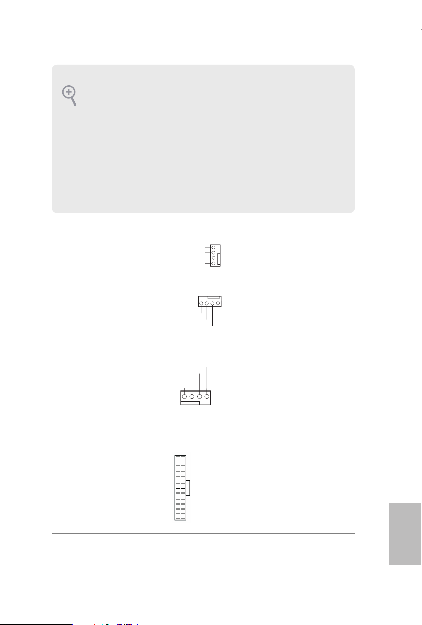
Chassis Fan Connectors
(4-pin CHA_FAN1)
(see p.6 or 7, No. 17)
(4-pin CHA_FAN2)
(see p.6 or 7, No. 10)
CPU Fan Connector
(4-pin CPU_FAN1)
(see p.6 or 7, No. 2)
ATX Power Connector
(24-p in ATXPWR1)
(see p.6 or 7, No. 4)
CHA_FAN_SPEED
+12V
GND
FAN_SPEED_CONTROL
CHA_FAN_SPEED
FAN_VOLTAGE
CPU_FAN_SPEED
+12V
GND
12
24
1
13
Please connect fan cables
3
2
to the fan connectors and
1
match the black wire to
the ground pin.
is motherboard pro-
vides a 4-Pin CPU fan
(Quiet Fan) connector.
If you plan to connect a
3-Pin CPU fan, please
connect it to Pin 1-3.
is motherboard pro-
vides a 24-pin ATX power
connector. To use a 20-pin
ATX power supply, please
plug it along Pin 1 and Pin
13.
English
29
Page 36
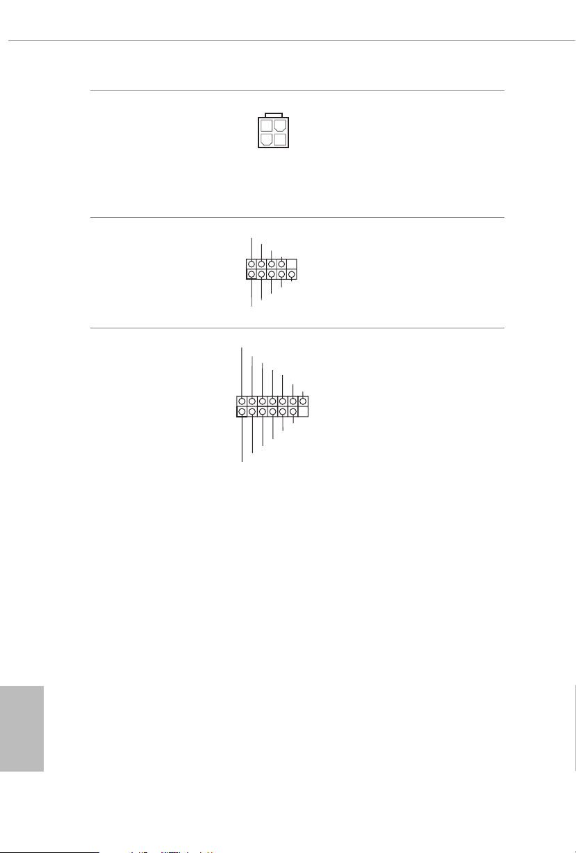
ATX 12V Power
1
RRI#1
1
SPI_DQ3
#
Connector
(4-pin ATX12V1)
(see p.6 or 7, No. 1)
Please connect an ATX
12V power supply to this
connector.
*e power supply plug
ts into this connector in
only one orientation.
Serial Port Header
(9-pin COM1)
(see p.6 or 7, No. 13)
SPI TPM Header
(13 -pi n SPI_TPM _J1)
(see p.6 or 7, No. 16)
RRXD1
DDCD#1
+3.3V
SPI_CS0
SPI_DQ2
DDTR#1
DDSR#1
GND
TTXD1
Dummy
CLK
RSMRST#
SPI_MISO
CCTS#1
RRTS#1
SPI_MOSI
RST#
TPM_PIRQ
SPI_TPM_CS
GND
is COM1 header
supports a serial port
module.
is connector supports SPI
Trusted Platform Module (TPM)
system, which can securely store
keys, digital certicates, pass-
words, and data. A TPM system
also helps enhance network
security, protects digital
identities, and ensures platform
integrity.
English
30
Page 37
A520M/ac
3
2.7 M.2_SSD (NGFF) Module Installation Guide
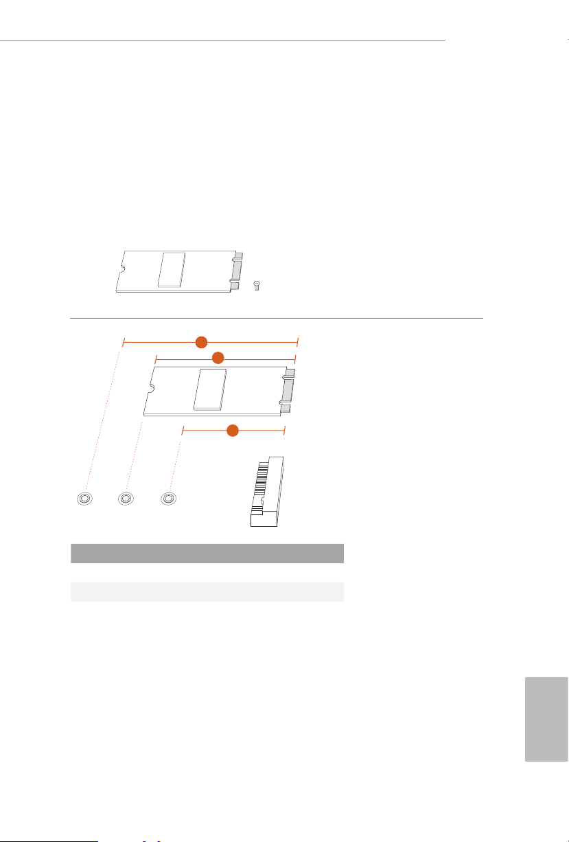
The M.2, also known as the Next Generation Form Factor (NGFF), is a small size and
versatile card edge connector that aims to replace mPCIe and mSATA. The Ultra M.2
Socket supports M Key type 2242/2260/2280 M.2 SATA3 6.0 Gb/s module and M.2 PCI
Express module up to Gen3 x4 (32 Gb/s).
Installing the M.2_SSD (NGFF) Module
Step 1
Prepare a M.2_SSD (NGFF) module
and the screw.
Step 2
2
1
Depending on the PCB type and
length of your M.2_SSD (NGFF)
module, nd the corresponding nut
location to be used.
ABC
No. 1 2 3
Nut Location A B C
PCB Length 4.2cm 6cm 8cm
Module Type Type 224 2 Ty pe2260 Ty pe 2 280
English
31
Page 38
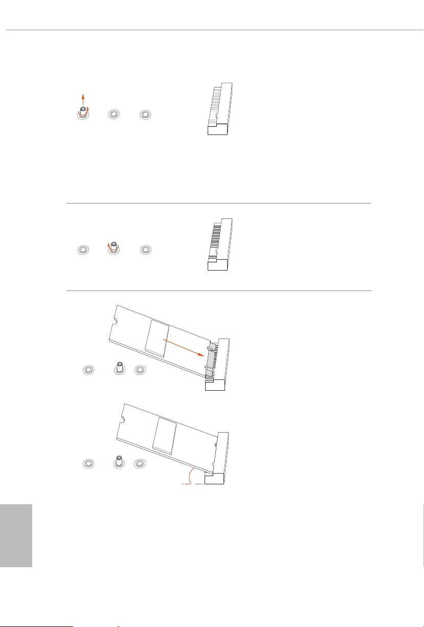
Step 3
Move the stando based on the
module type and length.
ABC
e stando is placed at the nut
location C by default. Skip Step 3
and 4 and go straight to Step 5 if you
are going to use the default nut.
Otherwise, release the stando by
hand.
Step 4
Peel o the yellow protective lm on
the nut to be used. Hand tighten the
ABC
stando into the desired nut location
on the motherboard.
Step 5
Gently insert the M.2 (NGFF) SSD
module into the M.2 slot. Please
be aware that the M.2 (NGFF) SSD
module only ts in one orientation.
ABC
English
32
ABC
o
20
Page 39
A520M/ac
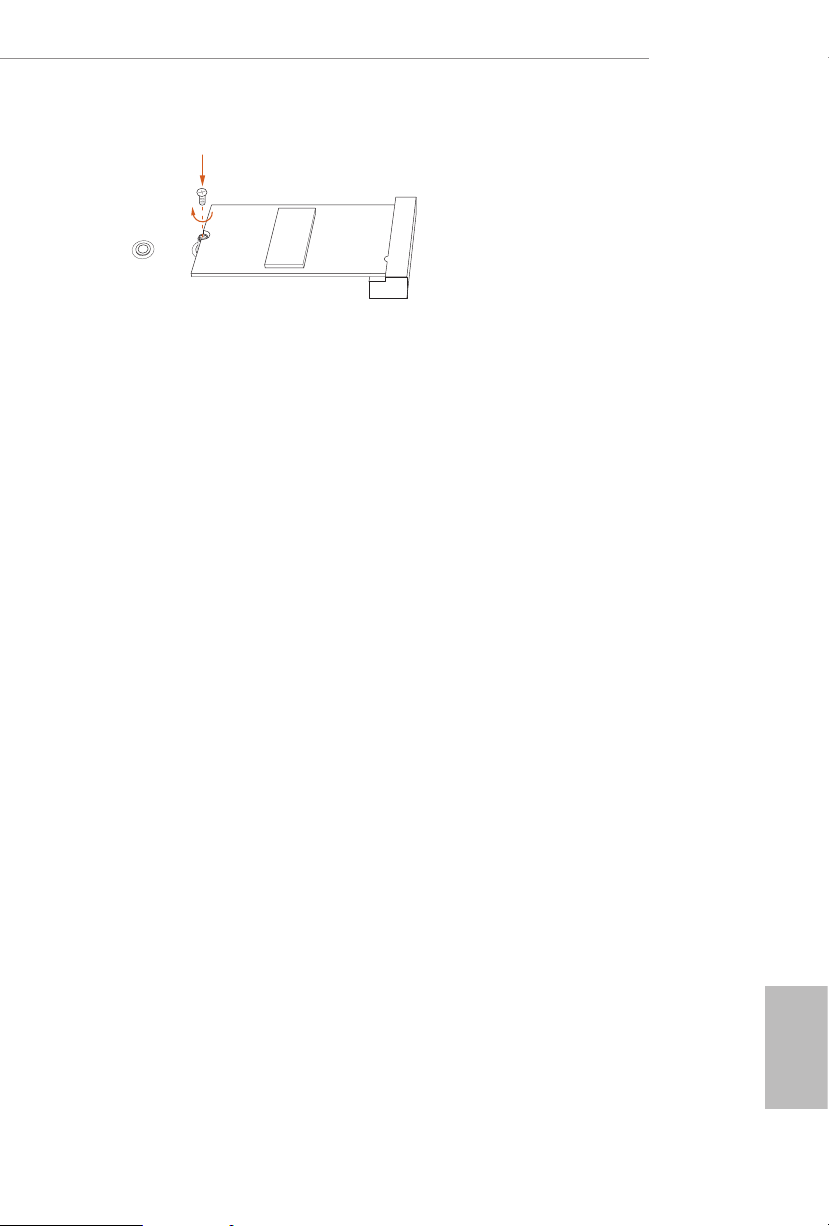
Step 6
Tighten the screw with a screwdriver
to secure the module into place.
Please do not overtighten the screw
C
NUT1NUT2
as this might damage the module.
33
English
Page 40

M.2_SSD (NGFF) Module Support List
Vendor Interface P/N
SanDisk PCIe SanDisk-SD6PP4M-128G( Gen2 x2)
Intel PCIe INTEL 6000P-SSDPEKKF256G7 (nvme)
Intel PCIe INTEL 6000P-SSDPEKKF512G7 (nvme)
Kingston PCIe Kingston SHPM2280P2 / 240G (Gen2 x4)
Samsung PCIe Samsung XP941-MZHPU512HCGL(Gen2x4)
ADATA SATA ADATA - AXNS381E-128GM-B
Crucial SATA Crucial-CT240M500SSD4-240GB
ezlink SATA ezlink P51B-80-120GB
Intel SATA INTEL 540S-SSDSCKKW240H6-240GB
Kingston SATA Kingston SM2280S3G2/120G - Win8.1
Kingston SATA Kingston-RBU-SNS8400S3 / 180GD
LITEON SATA LITEON LJH-256V2G-256GB (22 60)
PLEXTOR SATA PLEXTOR PX-128M6G-2260-128GB
PLEXTOR SATA PLEXTOR PX-128M7VG-128GB
SanDisk SATA SanDisk X400-SD8SN8U-128G
SanDisk SATA Sandisk Z400s-SD8SNAT-128G-1122
SanDisk SATA SanDisk-SD6SN1M-128G
Tra nscend SATA Transcend TS256GMTS800-256GB
V-Col or SATA V-Colo r 12 0G
V-Col or SATA V-Colo r 240G
WD SATA WD GREEN WDS240G1G0B-00RC30
For the latest updates of M.2_SSD (NFGG) module support list, please visit our website
for details: http://www.asrock.com
English
34
Page 41

Chapter 3 Software and Utilities Operation
3.1 Installing Drivers
e Support CD that comes with the motherboard contains necessary drivers and
useful utilities that enhance the motherboard’s features.
Running The Support CD
To begin using the support CD, insert the CD into your CD-ROM drive. e CD
automatically displays the Main Menu if “AUTORUN” is enabled in your computer.
If the Main Menu does not appear automatically, locate and double click on the le
“ASRSETUP.EXE” in the Support CD to display the menu.
Drivers Menu
e drivers compatible to your system will be auto-detected and listed on the
support CD driver page. Please click Install All or follow the order from top to
bottom to install those required drivers. erefore, the drivers you install can work
properly.
Utilities Menu
e Utilities Menu shows the application soware that the motherboard supports.
Click on a specic item then follow the installation wizard to install it.
A520M/ac
35
English
Page 42
3.2 ASRock Motherboard Utility (A-Tuning)
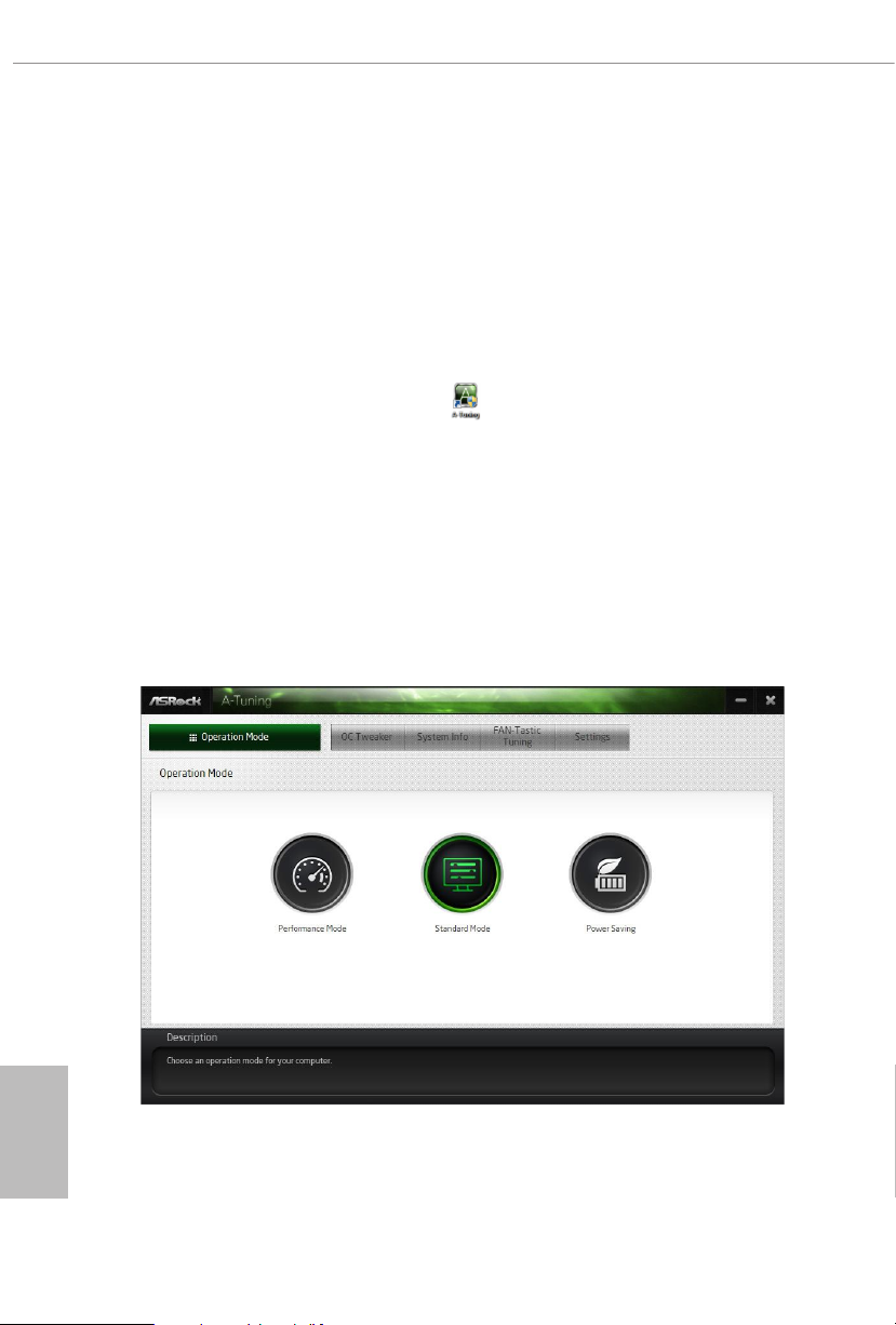
ASRock Motherboard Utility (A-Tuning) is ASRock’s multi purpose soware suite
with a new interface, more new features and improved utilities.
3.2.1 Installing ASRock Motherboard Utility (A-Tuning)
ASRock Motherboard Utility (A-Tuning) can be downloaded from ASRock Live
Update & APP Shop. Aer the installation, you will nd the icon “ASRock Mother-
board Utility (A-Tuning)“ on your desktop. Double-click the
“ASRock Motherboard Utility (A-Tuning)“ icon, ASRock Motherboard Utility
(A-Tu n i ng) main menu will pop up.
3.2.2 Using ASRock Motherboard Utility (A-Tuning)
ere are ve sections in ASRock Motherboard Utility (A-Tuning) main menu:
Operation Mode, OC Tweaker, System Info, FAN-Tastic Tuning and Settings.
Operation Mode
Choose an operation mode for your computer.
English
36
Page 43
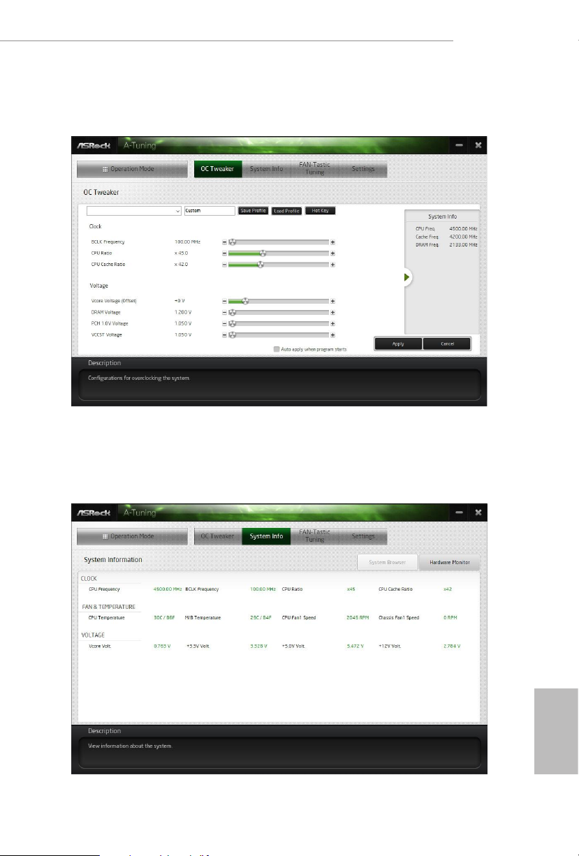
OC Tw eaker
Congurations for overclocking the system.
A520M/ac
System Info
View information about the system.
*e System Browser tab may not appear for certain models.
English
37
Page 44
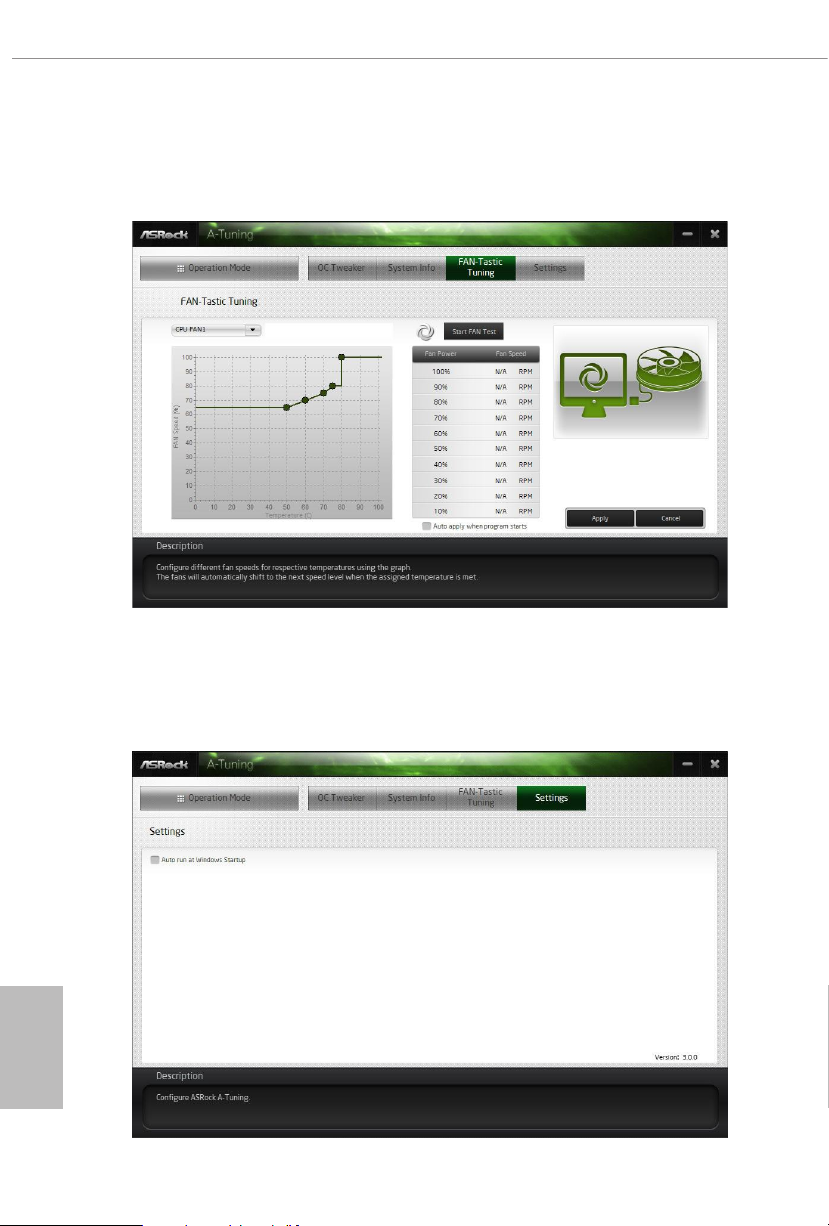
FAN-Tastic Tuning
Congure up to ve dierent fan speeds using the graph. e fans will automatically shi
to the next speed level when the assigned temperature is met.
Settings
Congure ASRock ASRock Motherboard Utility (A-Tuning). Click to select "Auto
run at Windows Startup" if you want ASRock Motherboard Utility (A-Tuning) to
be launched when you start up the Windows operating system.
English
38
Page 45
3.3 ASRock Live Update & APP Shop
e ASRock Live Update & APP Shop is an online store for purchasing and
downloading soware applications for your ASRock computer. You can quickly and
easily install various apps and support utilities. With ASRock Live Update & APP
Shop, you can optimize your system and keep your motherboard up to date simply
with a few clicks.
Double-click on your desktop to access ASRock Live Update & APP Shop
utility.
*You need to be connected to the Internet to download apps f rom the ASRock Live Update & APP Shop.
3.3.1 UI Overview
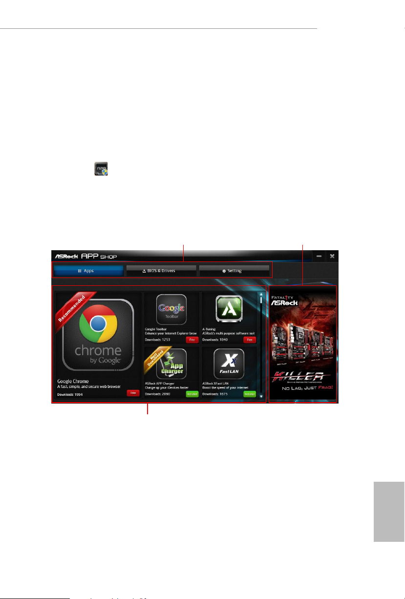
Category Panel
Hot News
A520M/ac
Information Panel
Category Panel: e category panel contains several category tabs or buttons that
when selected the information panel below displays the relative information.
Information Panel: e information panel in the center displays data about the
currently selected category and allows users to perform job-related tasks.
Hot News: e hot news section displays the various latest news. Click on the image
to visit the website of the selected news and know more.
English
39
Page 46
3.3.2 Apps
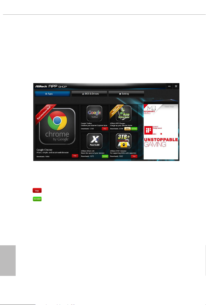
When the "Apps" tab is selected, you will see all the available apps on screen for you
to download.
Installing an App
Step 1
Find the app you want to install.
e most recommended app appears on the le side of the screen. e other various
apps are shown on the right. Please scroll up and down to see more apps listed.
English
40
You can check the price of the app and whether you have already intalled it or not.
- e red icon displays the price or "Free" if the app is free of charge.
- e green "Installed" icon means the app is installed on your computer.
Step 2
Click on the app icon to see more details about the selected app.
Page 47
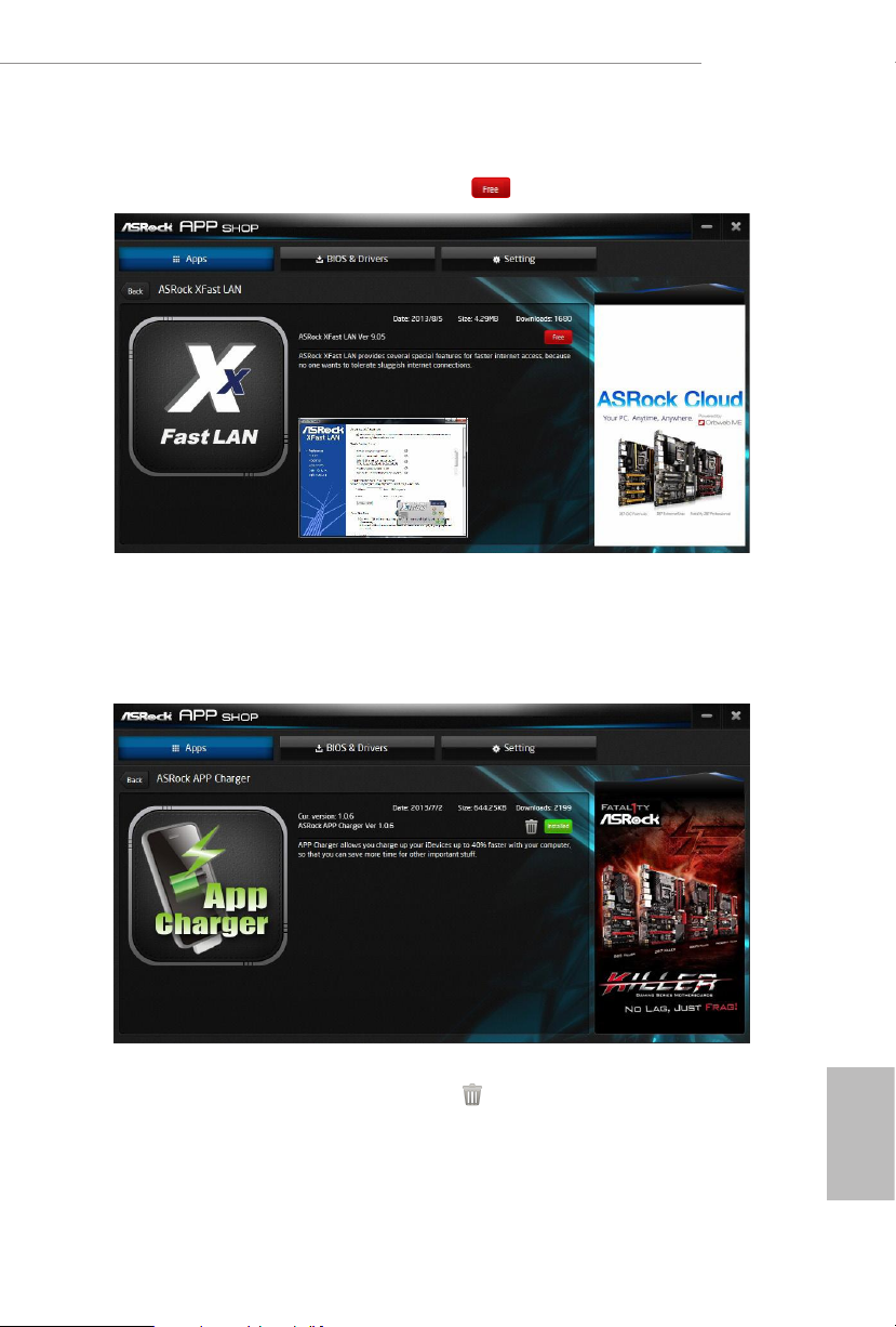
Step 3
If you want to install the app, click on the red icon to start downloading.
Step 4
When installation completes, you can nd the green "Installed " icon appears on the
upper right corner.
A520M/ac
To uninstall it, simply click on the trash can icon .
*e trash icon may not appear for certain apps.
English
41
Page 48
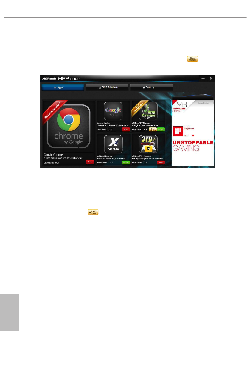
Upgrading an App
You can only upgrade the apps you have already installed. When there is an
available new version for your app, you will nd the mark of "New Version"
appears below the installed app icon.
Step 1
Click on the app icon to see more details.
Step 2
Click on the yellow icon to start upgrading.
English
42
Page 49
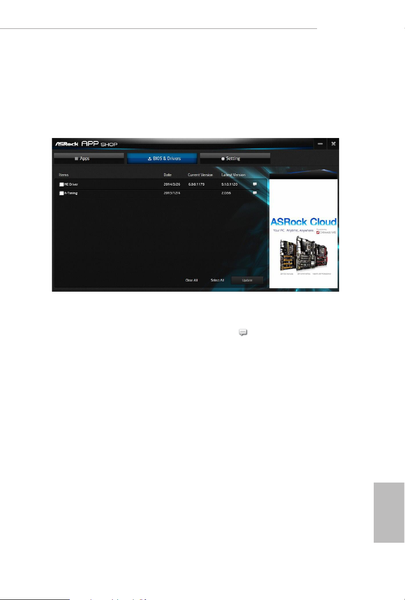
3.3.3 BIOS & Drivers
Installing BIOS or Drivers
When the "BIOS & Drivers" tab is selected, you will see a list of recommended or
critical updates for the BIOS or drivers. Please update them all soon.
A520M/ac
Step 1
Please check the item information before update. Click on to see more details.
Step 2
Click to select one or more items you want to update.
Step 3
Click Update to start the update process.
English
43
Page 50
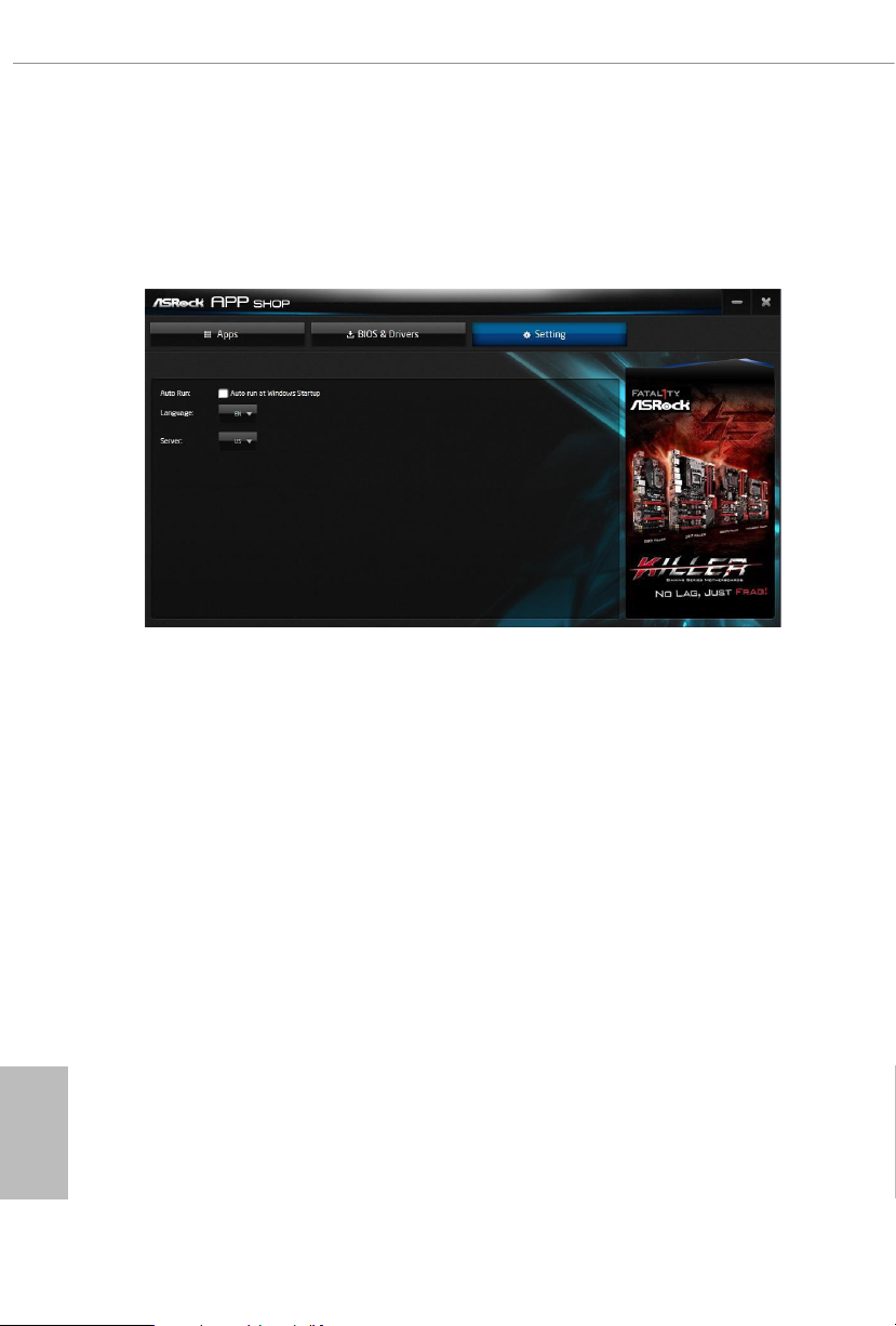
3.3.4 Setting
In the "Setting" page, you can change the language, select the server location, and
determine if you want to automatically run the ASRock Live Update & APP Shop
on Windows startup.
English
44
Page 51
Chapter 4 UEFI SETUP UTILITY
4.1 Introduction
is section explains how to use the UEFI SETUP UTILITY to congure your
system. You may run the UEFI SETUP UTILITY by pressing <F2> or <Del> right
aer you power on the computer, otherwise, the Power-On-Self-Test (POST) will
continue with its test routines. If you wish to enter the UEFI SETUP UTILITY aer
POST, restart the system by pressing <Ctl> + <Alt> + <Delete>, or by pressing the
reset button on the system chassis. You may also restart by turning the system o
and then back on.
Becau se the UEFI soware is constantly being upd ated, the following UEFI setup
screens and de scriptions are for refe rence purpose only, and they may not exactly
match what you see on your scre en.
4.1.1 UEFI Menu Bar
e top of the screen has a menu bar with the following selections:
A520M/ac
Main
OC Tweaker
Advanced
Tool
H/W Monitor
Security
Boot
Exit
For setting system time/date information
For overclocking congurations
For advanced system congurations
Useful tools
Displays current hardware status
For security settings
For conguring boot settings and boot priority
Exit the current screen or the UEFI Setup Utility
English
45
Page 52
4.1.2 Navigation Keys
Use < > key or < > key to choose among the selections on the menu bar, and
use < > key or < > key to move the cursor up or down to select items, then
press <Enter> to get into the sub screen. You can also use the mouse to click your
required item.
Please check the following table for the descriptions of each navigation key.
Navigation Key(s) Description
+ / -
<Tab>
<PGUP>
<PGDN>
<HOME>
<END>
<F1>
<F7>
<F9>
<F10>
<F12>
<ESC>
To change option for the selected items
Switch to next function
Go to the previous page
Go to the next page
Go to the top of the screen
Go to the bottom of the screen
To display the General Help Screen
Discard changes and exit the SETUP UTILITY
Load optimal default values for all the settings
Save changes and exit the SETUP UTILITY
Print screen
Jump to the Exit Screen or exit the current screen
English
46
Page 53
4.2 Main Screen
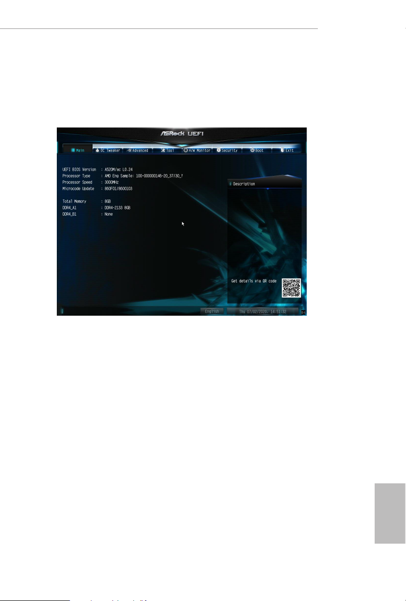
When you enter the UEFI SETUP UTILITY, the Main screen will appear and
display the system overview.
A520M/ac
47
English
Page 54
4.3 OC Tweaker Screen
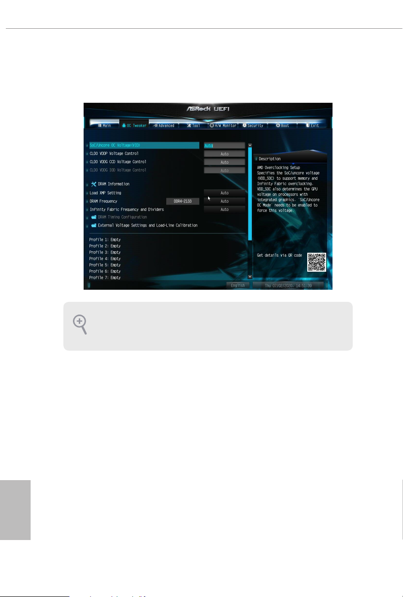
In the OC Tweaker screen, you can set up overclocking features.
Becau se the UEFI soware is constantly being upd ated, the following UEFI setup
screens and de scriptions are for refe rence purpose only, and they may not exactly
match what you see on your scre en.
English
48
SoC/Uncore OC Voltage(VID)
Specify the SoC/Uncore voltage (VDD_SOC) in mV to support memory and Innity Fabric
overclocking. VDD_SOC also determines the GPU voltage on processors with integrated
graphics. “SoC/Uncore OC Mode” needs to be enabled to force this voltage.
CLD0 VDDP Voltage Control
AMD Overclocking Setup VDDP is a voltage for the DDR4 bus signaling (PHY), and it is
derived from your DRAM Voltage (VDDIO_Mem). As a result, VDDP voltage in mV can
approach but not exceed your DRAM Voltage.
CLD0 VDDG CCD Voltage Control
AMD Overclocking Setup VDDG CCD represents voltage for the data portion of the Innity
Fabric. It is derived from the CPU SoC/Uncore Voltage (VDD_SOC). VDDG can approach
but not exceed VDD_SOC.
Page 55

A520M/ac
CLD0 VDDG IOD Voltage Control
AMD Overclocking Setup VDDG IOD represents voltage for the data portion of the Innity
Fabric. It is derived from the CPU SoC/Uncore Voltage (VDD_SOC). VDDG can approach
but not exceed VDD_SOC.
DRAM Information
Load XMP Setting
Load XMP settings to overclock the memory and perform beyond standard
specications.
DRAM Frequency
If [Auto] is selected, the motherboard will detect the memory module(s) inserted
and assign the appropriate frequency automatically. Setting DRAM Frequency can
adjust DRAM Timing.
Innity Fabric Frequency and Dividers
AMD Overclocking Setup Set Innity Fabric frequency (FCLK). Auto: FCLK =
MCLK. Manual: FCLK must be less than or equal to MCLK for best performance in
most cases. Latency penalties are incurred if FCLK and MCLK are mismatched, but
suciently high MCLK can negate or overcome this penalty.
DRAM Timing Conguration
External Voltage Settings and Load-line Calibration
+1.8V Voltage
Congure the voltage for the +1.8V Voltage. e default value is [Auto].
DRAM Voltage
Congure the voltage for the DRAM Voltage.
VDDP
Congure the voltage for the VDDP.
Save User Default
Type a prole name and press enter to save your settings as user default.
English
49
Page 56

Load User Default
Load previously saved user defaults.
Save User UEFI Setup Prole to Disk
It helps you to save current UEFI settings as an user prole to disk.
Load User UEFI Setup Prole from Disk
You can load previous saved prole from the disk.
English
50
Page 57
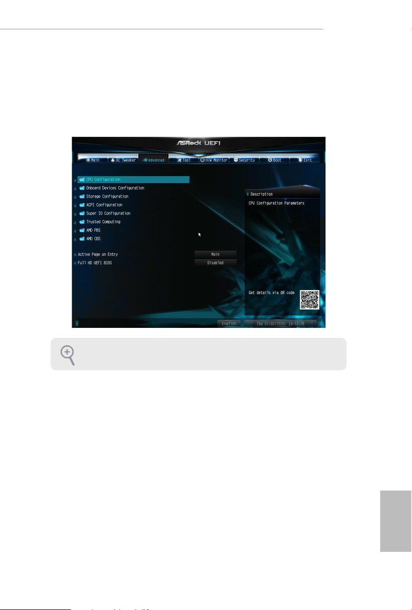
4.4 Advanced Screen
In this section, you may set the congurations for the following items: CPU
Conguration, Onboard Devices Conguration, Storage Conguration, ACPI
Conguration, Super IO Conguration, Trusted Computing, AMD PBS, AMD
Overclocking and AMD CBS.
A520M/ac
Setting wrong values in this sec tion may cause the system to malfunction.
UEFI Conguration
Active Page on Entry
Select the default page when entering the UEFI setup utility.
Full HD UEFI
When [Auto] is selected, the resolution will be set to 1920 x 1080 if the monitor
supports Full HD resolution. If the monitor does not support Full HD resolution,
then the resolution will be set to 1024 x 768. When [Disable] is selected, the
resolution will be set to 1024 x 768 directly.
English
51
Page 58
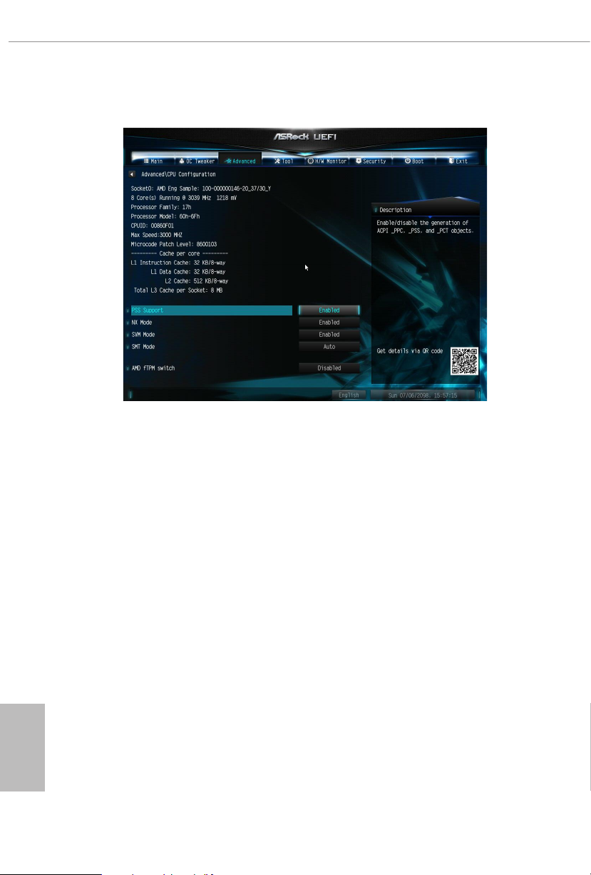
4.4.1 CPU Conguration
PSS Support
Use this to enable or disable the generation of ACPI_PPC, _PSS, and _PCT objects.
NX Mode
Use this to enable or disable NX mode.
English
52
SVM Mode
When this is set to [Enabled], a VMM (Virtual Machine Architecture)can utilize the
additional hardware capabilities provided by AMD-V. e default value is [Enabled].
Coniguration options: [Enabled] and [Disabled].
SMT Mode
is item can be used to disable symmetric multithreading. To re-enable SMT, a
power cycle is needed aer selecting [Auto].
Warning: S3 is not supported on systems where SMT is disabled.
AMD fTPM Switch
Use this to enable or disable AMD CPU fTPM.
Page 59
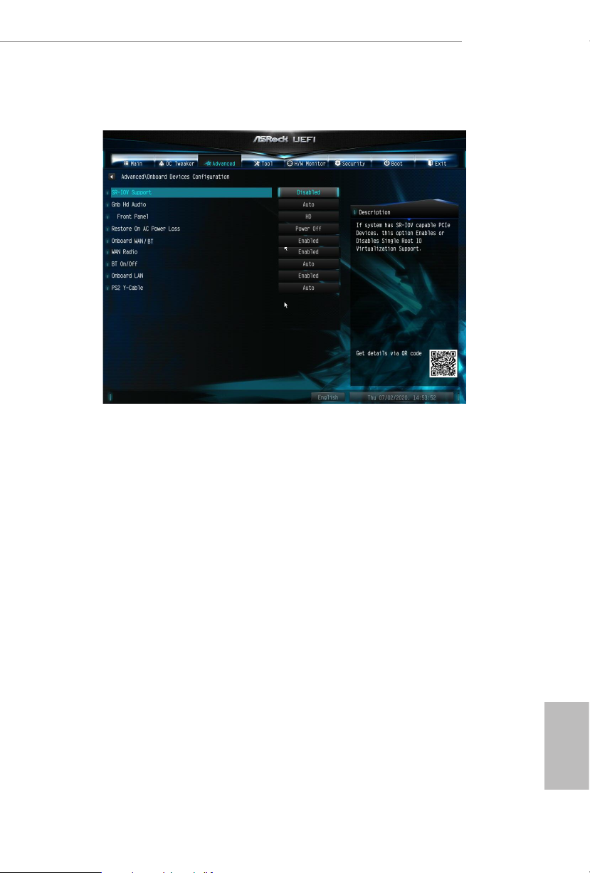
4.4.2 Onboard Devices Conguration
SR-IOV Support
Enable/disable the SR-IOV (Single Root IO Virtualization Support) if the system
has SR-IOV capable PCIe devices.
A520M/ac
UMA Frame buer Size
is item allows you to set the size of the UMA frame buer.
(Only for processor with integrated graphics)
Gnb HD Audio
Enable/disable onboard HD audio. Set to Auto to enable onboard HD audio and
automatically disable it when a sound card is installed.
Front Panel
Enable/disable front panel HD audio.
Restore on AC/Power Loss
Select the power state aer a power failure. If [Power O] is selected, the power will
remain o when the power recovers. If [Power On] is selected, the system will start
to boot up when the power recovers.
English
53
Page 60

Onboard WAN/BT
Use this item to enable or disable the onboard WAN/BT device.
WAN Radio
Congure the WiFi module's connectivity.
BT On/O
Enable/disable the bluetooth.
Onboard LAN
Enable or disable the onboard network interface controller.
PS2 Y- Cable
Enable the PS2 Y-Cable or set this option to Auto.
English
54
Page 61
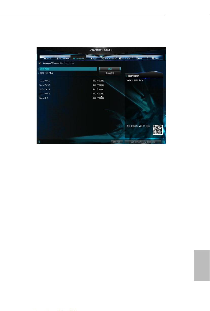
4.4.3 Storage Conguration
SATA M o de
AHCI: Supports new features that improve performance.
A520M/ac
RAID: Combine multiple disk drives into a logical unit.
SATA Hot Plug
Enable/disable the SATA Hot Plug function.
English
55
Page 62
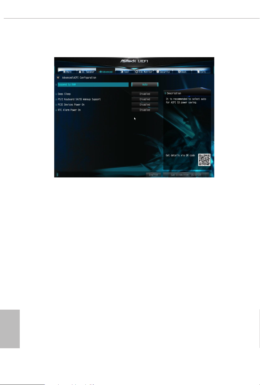
4.4.4 ACPI Conguration
Suspend to RAM
It is recommended to select auto for ACPI S3 power saving.
Deep Sleep
Congure deep sleep mode for power saving when the computer is shut down.
English
56
PS/2 Keyboard S4/S5 Wakeup Support
Allow the system to be waked up by a PS/2 Keyboard in S4/S5.
PCIE Devices Power On
Allow the system to be waked up by a PCIE device and enable wake on LAN.
RTC Alarm Power On
Allow the system to be waked up by the real time clock alarm. Set it to By OS to let
it be handled by your operating system.
Page 63

4.4.5 Super IO Conguration
Serial Port 1
Enable or disable the Serial port 1.
A520M/ac
Serial Port Address
Select the address of the Serial port.
English
57
Page 64
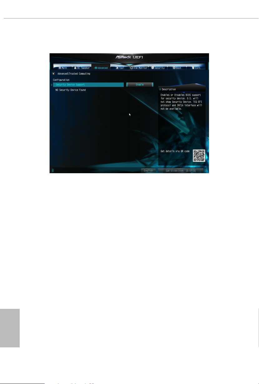
4.4.6 Trusted Computing
Security Device Support
Enable or disable BIOS support for security device.
English
58
Page 65
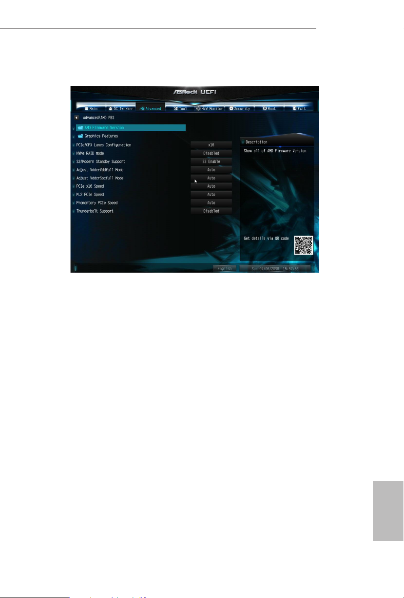
4.4.7 AMD PBS
e AMD PBS menu accesses AMD specic features.
A520M/ac
59
English
Page 66
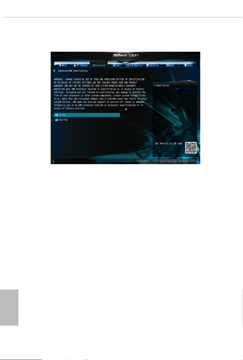
4.4.8 AMD Overclocking
e AMD Overclocking menu accesses options for conguring CPU frequency and
voltage.
English
60
Page 67
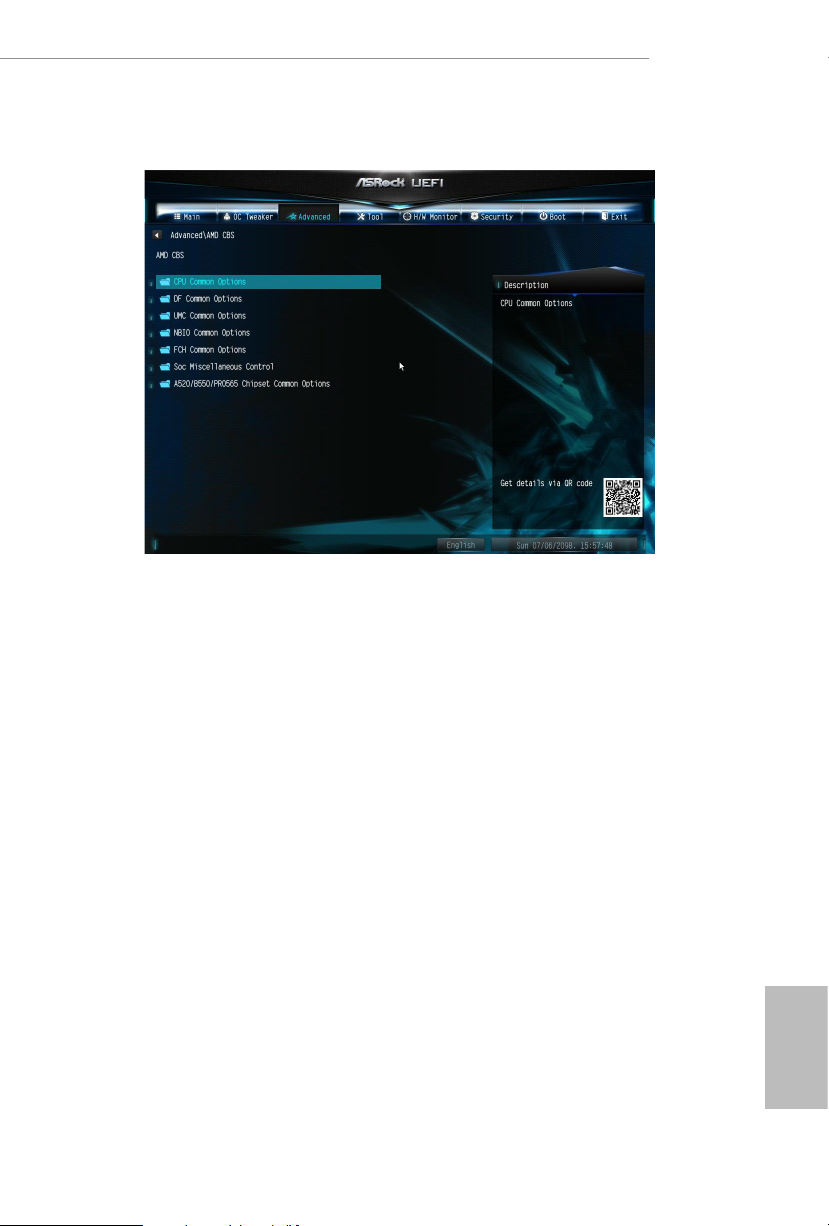
4.4.9 AMD CBS
e AMD CBS menu accesses AMD specic features.
A520M/ac
61
English
Page 68
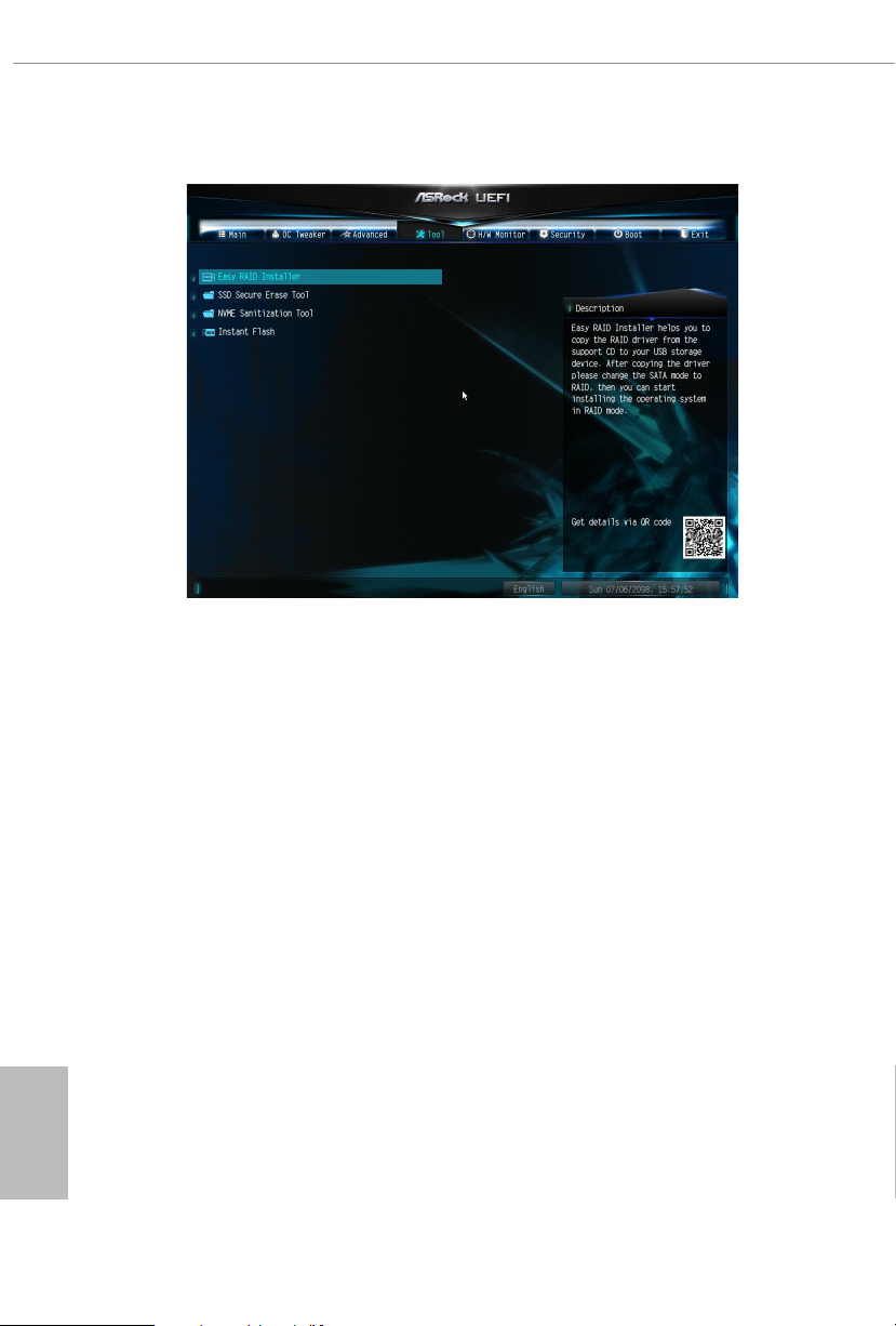
4.5 Tools
Easy RAID Installer
Easy RAID Installer helps you to copy the RAID driver from the support CD to
your USB storage device. Aer copying the drivers please change the SATA mode to
RAID, then you can start installing the operating system in RAID mode.
SSD Secure Erase Tool
Use this tool to securely erase SSD.
English
62
NVME Sanitization Tool
Aer you sanitize SSD, all user data will be permantly destroyed on the SSD and
cannot be recovered.
Instant Flash
Save UEFI les in your USB storage device and run Instant Flash to update your
UEFI.
Page 69
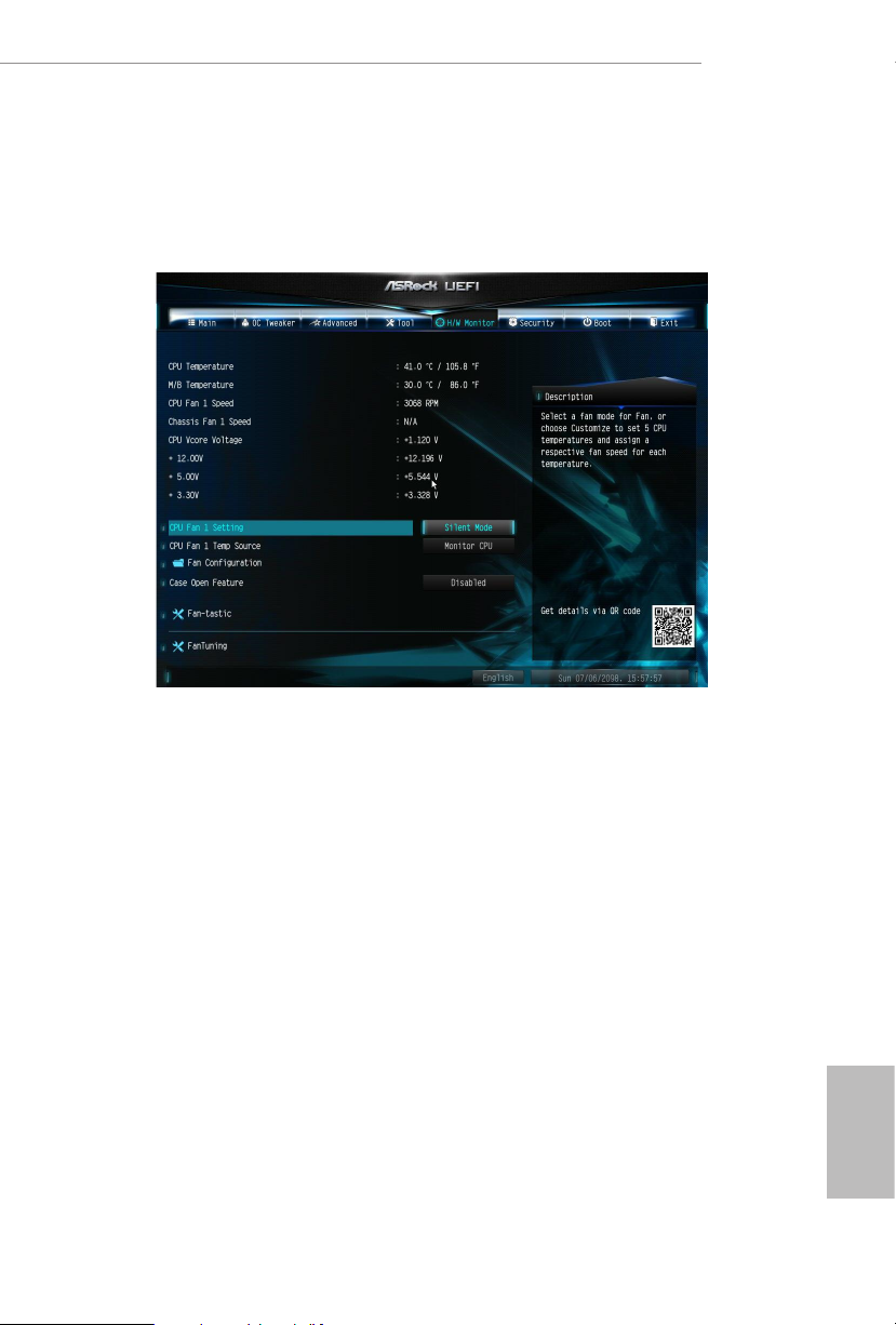
4.6 Hardware Health Event Monitoring Screen
is section allows you to monitor the status of the hardware on your system,
including the parameters of the CPU temperature, motherboard temperature, fan
speed and voltage.
A520M/ac
CPU FAN1 Setting
Select a fan mode for CPU Fan 1, or choose Customize to set 5 CPU temperatures
and assign a respective fan speed for each temperature.
CPU FAN1 Temp Source
Select a fan temperature source for CPU Fan 1.
FAN Conguration
Chassis Fan 1 Setting
Select a fan mode for Chassis Fan 1, or choose Customize to set 5 CPU temperatures
and assign a respective fan speed for each temperature.
Chassis Fan 1 Temp Source
Select a fan temperature source for Chassis Fan 1.
English
63
Page 70

Fan-Tastic
Select a fan mode for Fan, or choose Customize to set 5 CPU temperatures and assign a
respective fan speed for each temperature.
FanTuni n g
Detect the lowest fan speed in the system. Iy may take 3-5 minutes to complete.
English
64
Page 71
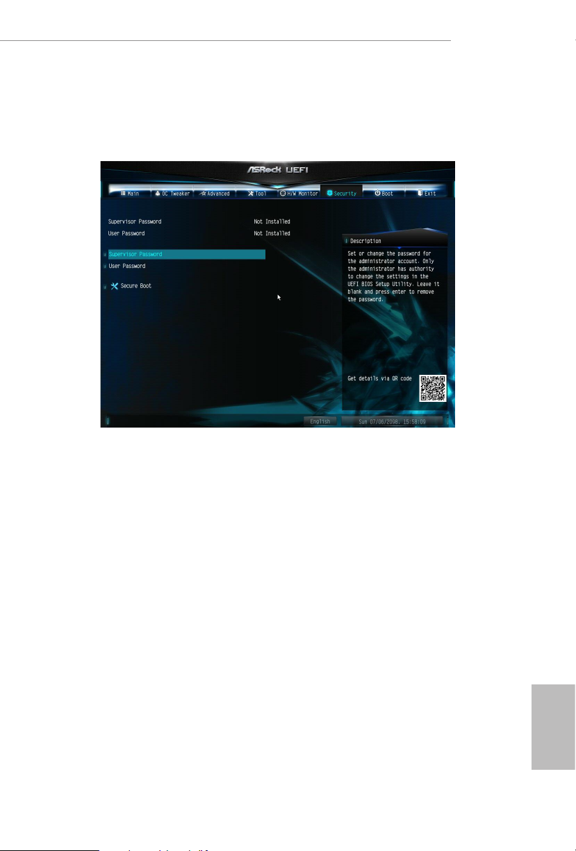
4.7 Security Screen
In this section you may set or change the supervisor/user password for the system.
You may also clear the user password.
Supervisor Password
Set or change the password for the administrator account. Only the administrator
has authority to change the settings in the UEFI Setup Utility. Leave it blank and
press enter to remove the password.
A520M/ac
User Password
Set or change the password for the user account. Users are unable to change the
settings in the UEFI Setup Utility. Leave it blank and press enter to remove the
password.
Secure Boot
Enable to support Secure Boot.
English
65
Page 72
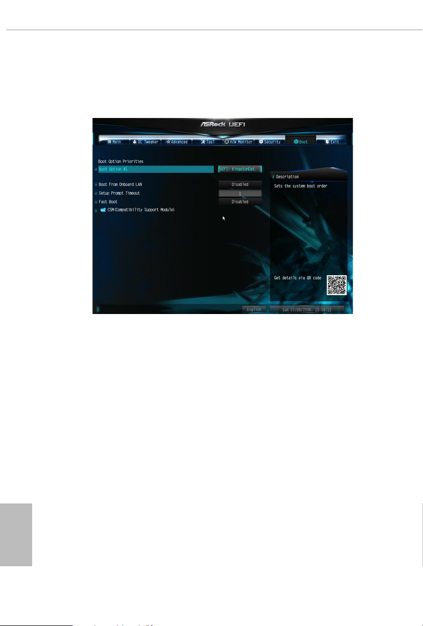
4.8 Boot Screen
is section displays the available devices on your system for you to congure the
boot settings and the boot priority.
Boot From Onboard LAN
Allow the system to be waked up by the onboard LAN.
Setup Prompt Timeout
Congure the number of seconds to wait for the setup hot key.
English
66
Fast Boot
Fast Boot minimizes your computer's boot time. In fast mode you may not boot
from an USB storage device.
Page 73
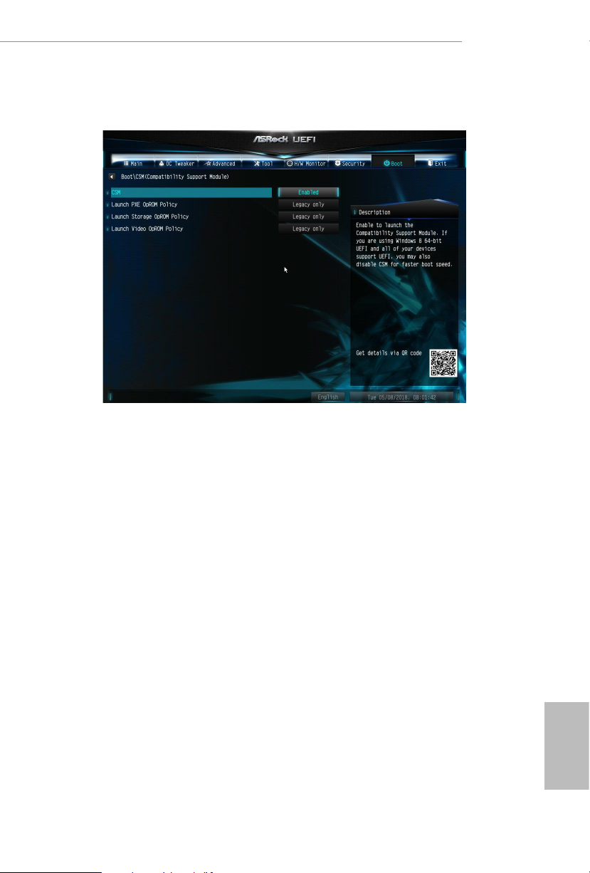
CSM (Compatibility Support Module)
CSM
Enable to launch the Compatibility Support Module. Please do not disable unless
you’re running a WHCK test.
A520M/ac
Launch PXE OpROM Policy
Select UEFI only to run those that support UEFI option ROM only. Select Legacy
only to run those that support legacy option ROM only. Select Do not launch to not
execute both legacy and UEFI option ROM.
Launch Storage OpROM Policy
Select UEFI only to run those that support UEFI option ROM only. Select Legacy
only to run those that support legacy option ROM only. Select Do not launch to not
execute both legacy and UEFI option ROM.
Bootup Num-Lock
Select whether Num Lock should be turned on or o when the system boots up.
Full Screen Logo
Enable to display the boot logo or disable to show normal POST messages.
English
67
Page 74

AddOn ROM Display
Enable AddOn ROM Display to see the AddOn ROM messages or congure the Ad-
dOn ROM if you’ve enabled Full Screen Logo. Disable for faster boot speed.
English
68
Page 75
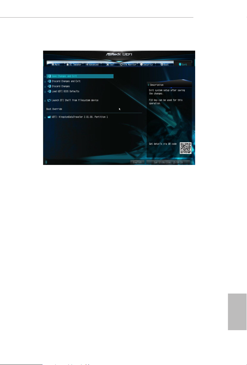
4.9 Exit Screen
Save Changes and Exit
When you select this option the following message, “Save conguration changes
and exit setup?” will pop out. Select [OK] to save changes and exit the UEFI SETUP
UTILITY.
A520M/ac
Discard Changes and Exit
When you select this option the following message, “Discard changes and exit
setup?” will pop out. Select [OK] to exit the UEFI SETUP UTILITY without saving
any changes.
Discard Changes
When you select this option the following message, “Discard changes?” will pop
out. Select [OK] to discard all changes.
Load UEFI BIOS Defaults
Load UEFI BIOS Default values for all the setup questions. e F9 key can be used
for this operation.
English
69
Page 76

DECLARATION OF CONFORMITY
Per FCC Part 2 Section 2.1077(a)
Responsible Party Name: ASRock Incorporation
Address:
13848 Magnolia Ave, Chino, CA91710
+1-909-590-8308/+1-909-590-1026
Phone/FaxNo:
hereby declares that the product
Product Name : Motherboard
Model Number :
Conforms to the following specications:
FCC Part 15, Subpart B, Unintentional Radiators
Supplementary Information:
is device complies with part 15 of the FCC Rules. Operation is subject to the
following two conditions: (1) is device may not cause harmful interference,
and (2) this device must accept any interference received, including interference
that may cause undesired operation.
Representative Person’s Name:
James
Signature :
Date :
May 12, 2017
Contact Information
If you need to contact ASRock or want to know more about ASRock, you’re welcome
to visit ASRock’s website at http://ww w.asrock.com; or you may contact your dealer
for further information. For technical questions, please submit a support request
form at https://event.asrock.com/tsd.asp
ASRock Incorporation
2F., No.37, Sec. 2, Jhongyang S. Rd., Beitou District,
Taipei City 112, Taiwan (R.O.C.)
ASRock EUROPE B.V.
Bijsterhuizen 11-11
6546 AR Nijmegen
e Netherlands
Phone: +31-24-345-44-33
Fax: +31-24-345-44-38
ASRock America, Inc.
13848 Magnolia Ave, Chino, CA91710
U.S.A.
Phone: +1-909-590-8308
Fax: +1-909-590-1026
Page 77

DECLARATION OF CONFORMITY
Per FCC Part 2 Section 2.1077(a)
Responsible Party Name: ASRock Incorporation
Address:
Phone/FaxNo:
hereby declares that the product
Product Name : Motherboard
13848 Magnolia Ave, Chino, CA91710
+1-909-590-8308/+1-909-590-1026
Model Number :
Conforms to the following specications:
FCC Part 15, Subpart B, Unintentional Radiators
Supplementary Information:
A520M/ac
is device complies with part 15 of the FCC Rules. Operation is subject to the
following two conditions: (1) is device may not cause harmful interference,
and (2) this device must accept any interference received, including interference
that may cause undesired operation.
James
Representative Person’s Name:
Signature :
Date :
May 12, 2017
Page 78
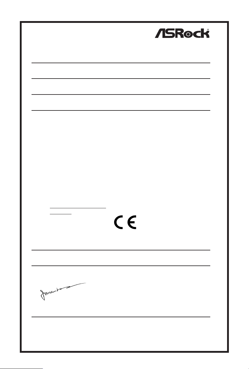
EU Declaration of Conformity
EMC —Directive 2014/30/EU (from April 20th, 2016)
ڛ
(EU conformity marking)
For the following equipment:
Motherboard
(Product Name)
A520M/ac / ASRock
(Model Designation / Trade Name)
ASRock Incorporation
(Manufacturer Name)
2F., No.37, Sec. 2, Jhongyang S. Rd., Beitou District, Taipei City 112, Taiwan (R.O.C.)
(Manufacturer Address)
☐ EN 55022:2010/AC:2011 Class B EN 55024:2010/A1:2015
ڛ EN 55032:2012+AC:2013 Class B ڛ
ڛ EN 61000-3-2:2014
ڛ RED
—
Directive 2014/53/EU
EN 300 328 V2.1.1 EN 301 489-17 V3.1.1
☐
☐
EN 301 893 V2.1.1 ☐ EN 301 489-3 V2.1.1
☐ EN 300 220 V3.1.1
☐
LVD —Directive 2014/35/EU (from April 20th, 2016)
☐
EN 60950-1 : 2011+ A2: 2013 ☐ EN 60950-1 : 2006/A12: 2011
ڛ RoHS — Directive 2011/65/EU
ڛ CE marking
ASRock EUROPE B.V.
(Company Name)
Bijsterhuizen 1111 6546 AR Nijmegen e Netherlands
(Company Address)
Person responsible for making this declaration:
(Name, Surname)
A.V.P
(Position / Title)
July 21, 2020
(Date)
P/N: 15G062244000AK V1.0
ڛ
EN 61000-3-3:2013
ڛ
 Loading...