

Page 1

Aspire M1610/Veriton M261
Service Guide
Service guide files and updates are available
on the AIPG/CSD web; for more information,
please refer to http://csd.acer.com.tw
PRINTED IN TAIWAN
Page 2

Revision History
Please refer to the table below for the updates made on Aspire M1610/VeritonM261service guide.
Date Chapter Updates
II
Page 3

Copyright
Copyright © 2005 by Acer Incorporated. All rights reserved. No part of this publication may be reproduced,
transmitted, transcribed, stored in a retrieval system, or translated into any language or computer language, in
any form or by any means, electronic, mechanical, magnetic, optical, chemical, manual or otherwise, without
the prior written permission of Acer Incorporated.
Disclaimer
The information in this guide is subject to change without notice.
Acer Incorporated makes no representations or warranties, either expressed or implied, with respect to the
contents hereof and specifically disclaims any warranties of merchantability or fitness for any particular
purpose. Any Acer Incorporated software described in this manual is sold or licensed "as is". Should the
programs prove defective following their purchase, the buyer (and not Acer Incorporated, its distributor, or its
dealer) assumes the entire cost of all necessary servicing, repair, and any incidental or consequential
damages resulting from any defect in the software.
Acer is a registered trademark of Acer Corporation.
Intel is a registered trademark of Intel Corporation.
Pentium 4 and Celeron are trademarks of Intel Corporation.
Other brand and product names are trademarks and/or registered trademarks of their respective holders.
III
Page 4

Conventions
The following conventions are used in this manual:
SCREEN
MESSAGES
NOTE Gives bits and pieces of additional
WARNING Alerts you to any damage that might
CAUTION Gives precautionary measures to
IMPORTANT Reminds you to do specific actions
Denotes actual messages that appear
on screen.
information related to the current
topic.
result from doing or not doing specific
actions.
avoid possible hardware or software
problems.
relevant to the accomplishment of
procedures.
IV
Page 5

Preface
Before using this information and the product it supports, please read the following general information.
1. This Service Guide provides you with all technical information relating to the BASIC CONFIGURATION
decided for Acer's "global" product offering. To better fit local market requirements and enhance product
competitiveness, your regional office MAY have decided to extend the functionality of a machine (e.g.
add-on card, modem, or extra memory capability). These LOCALIZED FEATURES will NOT be covered
in this generic service guide. In such cases, please contact your regional offices or the responsible
personnel/channel to provide you with further technical details.
2. Please note WHEN ORDERING FRU PARTS, that you should check the most up-to-date information
available on your regional web or channel. If, for whatever reason, a part number change is made, it will
not be noted in the printed Service Guide. For ACER-AUTHORIZED SERVICE PROVIDERS, your Acer
office may have a DIFFERENT part number code to those given in the FRU list of this printed Service
Guide. You MUST use the list provided by your regional Acer office to order FRU parts for repair and
service of customer machines.
V
Page 6

VI
Page 7

Table of Contents
System Specifications 1
Features . . . . . . . . . . . . . . . . . . . . . . . . . . . . . . . . . . . . . . . . . . . . . . . . . . . . . . . . . . . .1
Mainboard Placement . . . . . . . . . . . . . . . . . . . . . . . . . . . . . . . . . . . . . . . . . . . . . . . . . .4
Block Diagram . . . . . . . . . . . . . . . . . . . . . . . . . . . . . . . . . . . . . . . . . . . . . . . . . . . . . . .5
Aspire M1610 Front Panel . . . . . . . . . . . . . . . . . . . . . . . . . . . . . . . . . . . . . . . . . . . . . .6
Aspire M1610 Rear Panel . . . . . . . . . . . . . . . . . . . . . . . . . . . . . . . . . . . . . . . . . . . . . . .7
Veriton M261 Front Panel . . . . . . . . . . . . . . . . . . . . . . . . . . . . . . . . . . . . . . . . . . . . . . .8
Veriton M261 Rear Panel . . . . . . . . . . . . . . . . . . . . . . . . . . . . . . . . . . . . . . . . . . . . . . .9
Hardware Specifications and Configurations . . . . . . . . . . . . . . . . . . . . . . . . . . . . . . .10
Processor Support . . . . . . . . . . . . . . . . . . . . . . . . . . . . . . . . . . . . . . . . . . . . . . .10
System Memory Interface . . . . . . . . . . . . . . . . . . . . . . . . . . . . . . . . . . . . . . . . . .10
System Clock . . . . . . . . . . . . . . . . . . . . . . . . . . . . . . . . . . . . . . . . . . . . . . . . . . .10
SIS672 Chipset . . . . . . . . . . . . . . . . . . . . . . . . . . . . . . . . . . . . . . . . . . . . . . . . . .10
SiS 968 MuTIOL 1G Media I/O . . . . . . . . . . . . . . . . . . . . . . . . . . . . . . . . . . . . . .11
Super I/O — IT8718F . . . . . . . . . . . . . . . . . . . . . . . . . . . . . . . . . . . . . . . . . . . . .11
Audio Sub-Systems — Realtek ALC888SCo-lay ALC888 . . . . . . . . . . . . . . . . .11
LAN — Realtek8211BL(default) co-lay 8201CL phy . . . . . . . . . . . . . . . . . . . . . .12
Universal Serial Bus . . . . . . . . . . . . . . . . . . . . . . . . . . . . . . . . . . . . . . . . . . . . . .12
TSB43AB23PDTG4 Host Controller . . . . . . . . . . . . . . . . . . . . . . . . . . . . . . . . . .12
Expansion Slots . . . . . . . . . . . . . . . . . . . . . . . . . . . . . . . . . . . . . . . . . . . . . . . . .12
Back Panel I/O . . . . . . . . . . . . . . . . . . . . . . . . . . . . . . . . . . . . . . . . . . . . . . . . . .12
Power & Power Management . . . . . . . . . . . . . . . . . . . . . . . . . . . . . . . . . . . . . . .13
Hardware Monitor Function . . . . . . . . . . . . . . . . . . . . . . . . . . . . . . . . . . . . . . . . .13
System BIOS . . . . . . . . . . . . . . . . . . . . . . . . . . . . . . . . . . . . . . . . . . . . . . . . . . .14
System Utilities 15
Entering Setup . . . . . . . . . . . . . . . . . . . . . . . . . . . . . . . . . . . . . . . . . . . . . . . . . . . . . .16
Product Information . . . . . . . . . . . . . . . . . . . . . . . . . . . . . . . . . . . . . . . . . . . . . . . . . .18
Standard CMOS Features . . . . . . . . . . . . . . . . . . . . . . . . . . . . . . . . . . . . . . . . . . . . .19
IDE Channel 0/1 Master . . . . . . . . . . . . . . . . . . . . . . . . . . . . . . . . . . . . . . . . . . .21
IDE Channel 0/1 Slave . . . . . . . . . . . . . . . . . . . . . . . . . . . . . . . . . . . . . . . . . . . .22
SATA Channel 1/2 Master . . . . . . . . . . . . . . . . . . . . . . . . . . . . . . . . . . . . . . . . .23
Advanced BIOS Features . . . . . . . . . . . . . . . . . . . . . . . . . . . . . . . . . . . . . . . . . . . . . .24
CPU Feature . . . . . . . . . . . . . . . . . . . . . . . . . . . . . . . . . . . . . . . . . . . . . . . . . . . .26
Hard Disk Boot Priority . . . . . . . . . . . . . . . . . . . . . . . . . . . . . . . . . . . . . . . . . . . .27
Advanced Chipset Features . . . . . . . . . . . . . . . . . . . . . . . . . . . . . . . . . . . . . . . . . . . .28
Internal Graphic Control . . . . . . . . . . . . . . . . . . . . . . . . . . . . . . . . . . . . . . . . . . .29
Integrated Peripherals . . . . . . . . . . . . . . . . . . . . . . . . . . . . . . . . . . . . . . . . . . . . . . . .30
Onboard IDE Device . . . . . . . . . . . . . . . . . . . . . . . . . . . . . . . . . . . . . . . . . . . . . .31
Onboard PCI Device . . . . . . . . . . . . . . . . . . . . . . . . . . . . . . . . . . . . . . . . . . . . . .32
Onboard Super IO Device . . . . . . . . . . . . . . . . . . . . . . . . . . . . . . . . . . . . . . . . . .33
Power Management . . . . . . . . . . . . . . . . . . . . . . . . . . . . . . . . . . . . . . . . . . . . . . . . . .34
PnP/PCI Configuration . . . . . . . . . . . . . . . . . . . . . . . . . . . . . . . . . . . . . . . . . . . . . . . .36
PC Health Status . . . . . . . . . . . . . . . . . . . . . . . . . . . . . . . . . . . . . . . . . . . . . . . . . . . .37
Frequency/Voltage Control . . . . . . . . . . . . . . . . . . . . . . . . . . . . . . . . . . . . . . . . . . . . .38
Load Optimized Defaults . . . . . . . . . . . . . . . . . . . . . . . . . . . . . . . . . . . . . . . . . . . . . .39
Set Supervisor/User Password . . . . . . . . . . . . . . . . . . . . . . . . . . . . . . . . . . . . . . . . . .40
Save & Exit Setup . . . . . . . . . . . . . . . . . . . . . . . . . . . . . . . . . . . . . . . . . . . . . . . . . . . .41
Exit Without Saving . . . . . . . . . . . . . . . . . . . . . . . . . . . . . . . . . . . . . . . . . . . . . . . . . . .42
i
Page 8

Table of Contents
Machine Disassembly and Replacement 43
General Information . . . . . . . . . . . . . . . . . . . . . . . . . . . . . . . . . . . . . . . . . . . . . . . . . .44
Before You Begin . . . . . . . . . . . . . . . . . . . . . . . . . . . . . . . . . . . . . . . . . . . . . . . .44
Disassembly Procedure . . . . . . . . . . . . . . . . . . . . . . . . . . . . . . . . . . . . . . . . . . . . . . .45
Aspire M1610/Veriton M261 Disassembly . . . . . . . . . . . . . . . . . . . . . . . . . . . . .45
Reassembly Procedure . . . . . . . . . . . . . . . . . . . . . . . . . . . . . . . . . . . . . . . . . . . . . . .52
Aspire M1610/Veriton M261 Reassembly . . . . . . . . . . . . . . . . . . . . . . . . . . . . . .52
Troubleshooting 59
Jumper and Connector Information 61
Mainboard Jumper Locations . . . . . . . . . . . . . . . . . . . . . . . . . . . . . . . . . . . . . . . . . . .61
Jumper Settings . . . . . . . . . . . . . . . . . . . . . . . . . . . . . . . . . . . . . . . . . . . . . . . . . . . . .62
Setting Jumpers . . . . . . . . . . . . . . . . . . . . . . . . . . . . . . . . . . . . . . . . . . . . . . . . .62
FRU (Field Replaceable Unit) List 69
Exploded Diagrams . . . . . . . . . . . . . . . . . . . . . . . . . . . . . . . . . . . . . . . . . . . . . . . . . .70
Aspire M1610 . . . . . . . . . . . . . . . . . . . . . . . . . . . . . . . . . . . . . . . . . . . . . . . . . . .70
Veriton M261 . . . . . . . . . . . . . . . . . . . . . . . . . . . . . . . . . . . . . . . . . . . . . . . . . . . .71
Parts Lists . . . . . . . . . . . . . . . . . . . . . . . . . . . . . . . . . . . . . . . . . . . . . . . . . . . . . . . . . .72
ii
Page 9

System Specifications
Features
Operating System
• Microsoft Windows Vista (Home Basic, Home Premium, Business)
Processor
• Socket Type: Intel
• Processor Type:
• Intel
• Intel
• Intel
Chipset
• SiS 672+968
®
Core 2 Duo 755 FSB 800/533 MHz
®
Pentium 4/D 775 FSB 800/533 MHz
®
Celeron/Celeron D775 FSB 800/533 MHz
®
Socket T LGA 775 pin
Chapter 1
PCB
• Form Factor: Mirco ATX
• Dimension/ Layer: 244mm x 221mm/4 layer
Memory
• Memory Type : DDRII 667/533/400
• Support single channel 64 bit mode with maximum memory size up to 2GB
• Support un-buffered DIMMs only
• DIMM Slot : 2
• Memory Max.: Support 128MB, 256MB, 512MB and 1GB DDR memory technologies
• Cpapcity :Up to 1 GB per DIMM with maximum memory size up to 2 GB
Graphics
• SiS 3+ GUI 2D/3D Graphic solution
• DX9 Shader Model 2.0 Dual Pixel Shading pipeline support
• 1 VGA port on rear
PCI
• PCI Express Slot Type:
• PCI Express x16 Slot Quantity: 1
• PCI Express x1 Slot Quantity: 1
• PCI Slot Type: PCI 2.3, 5V Slots
• PCI Slot Quantity: 2
Chapter 1 1
Page 10

FDD
• Slot Quantity: 1
• Support 3.5” Devices
IDE
• Slot Type: 40 pin PATA IDE slot
• Slot Quantity: 1
• Transfer rate support:
• PIO mode: 0/1/2/3/4
• ATA mode: 33/66/100 port supported
• Slot Type: SATA slot
• Slot Quantity: 2
• Transfer rate support: SATA 1.5 Gb/s and SATA 3.0 Gb/s
• Storage Type support: HDD/CD-ROM/CD-RW/DVD-ROM/DVD-RW/DVD+RW/DVD Dual/DVD
SuperMultiPlus
Audio
• Audio Type: HD audio codec
• Audio Channel: 7.1 channel
• Audio Controller: Realtek ALC888S
• Audio Chip: HD audio codec ALC888S HD codec 7.1 w/ S/PDIF out
• Support S/PDIF: S/PDIF out
• ATAPI analog line-level stereo inputs for AUX_IN
LAN
• Type: RealTek 8211BL
• Supports 10/100/1000MB Ethernet environment
• Support power down mode
IEEE 1394 (Reserved)
• IEEE 1394 Controller: Ti TSB43AB23PDTG4
• IEEE 1394 Port: 1 for rear I/O port
• On board connector: 1(2x5 pin)
USB
• Controller: SiS 968
• USB Type: 2. 0/1.1
• Connectors Quantity:
• 4 for rear I/O ports
• On-board header: 2 for front daughter board / 1 for sharing 2 rear USB port)
BIOS
• BIOS Type: Phoenix Award BIOS
• 4MB Flash BIOS
• Award PnP BIOS compatible with SM BIOS 2.4
2 Chapter 1
Page 11

• ACPI 2.0,
• Provides DMI 2.0, WFM 2.0, WOL, and SM Bus for system management.
I/O Connector
• Controller: Super I/O ITE 8718F-FX with hardware monitor
Rear I/O Connector
• 1 PS/2 Keyboard Port
• 1 PS/2 Mouse Port
• 1 Parallel Port
• 1 Serial Port
• 1 VGA Port
• 1 10/100/1000 LAN Port (RJ-45)
• 1 1394 Port
• 4 USB Ports
• 6 jacks follow HD audio definition
Onboard Connector
• 1 CPU socket • 1 3pin system fan connector
• 2 Memory slots • 1 24pin ATX interface PS3/PS2 SPS
connector
• 1 PCI Express x 16 slot • 1 2x7pin front panel IO header
• 1 PCI Express x 1 slot • 2 reserved 2pin GPIO connector
• 2 PCI slots • 1 on board buzzer
• 1 FDD slot • 1 1x3 pin Clear COM pin
• 1 PATA IDE slot • 1 RM
• 2 SATA IDE connectors • Color management for on board connector
• 3 2x5 pin Intel FPIO specification USB
pin connectors.
• 1 2x5 pin Intel FPIO spec. Microphone
In/Headphone Out pin connectors
• 1 serial port 2x5 pin connector • 1 2x2pin CPU SPS connector
• 1 AUX-In 4pin connector • 1 2x4 pin Internal speaker header
• 1 S/PDIF out 1x4pin connector • 1 2x5pin 1394 connector
• 1 4pin CPU Fan connector
• Reserve position for 1 2*5pin 1394
connector
• Reserved 1 2x5pin IRDA
Power Supply
• PSP Type: 250W
Chapter 1 3
Page 12
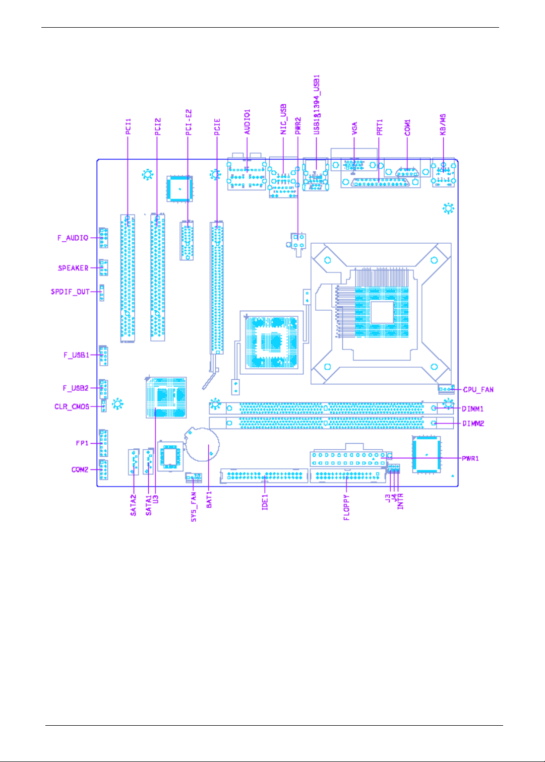
Mainboard Placement
4 Chapter 1
Page 13
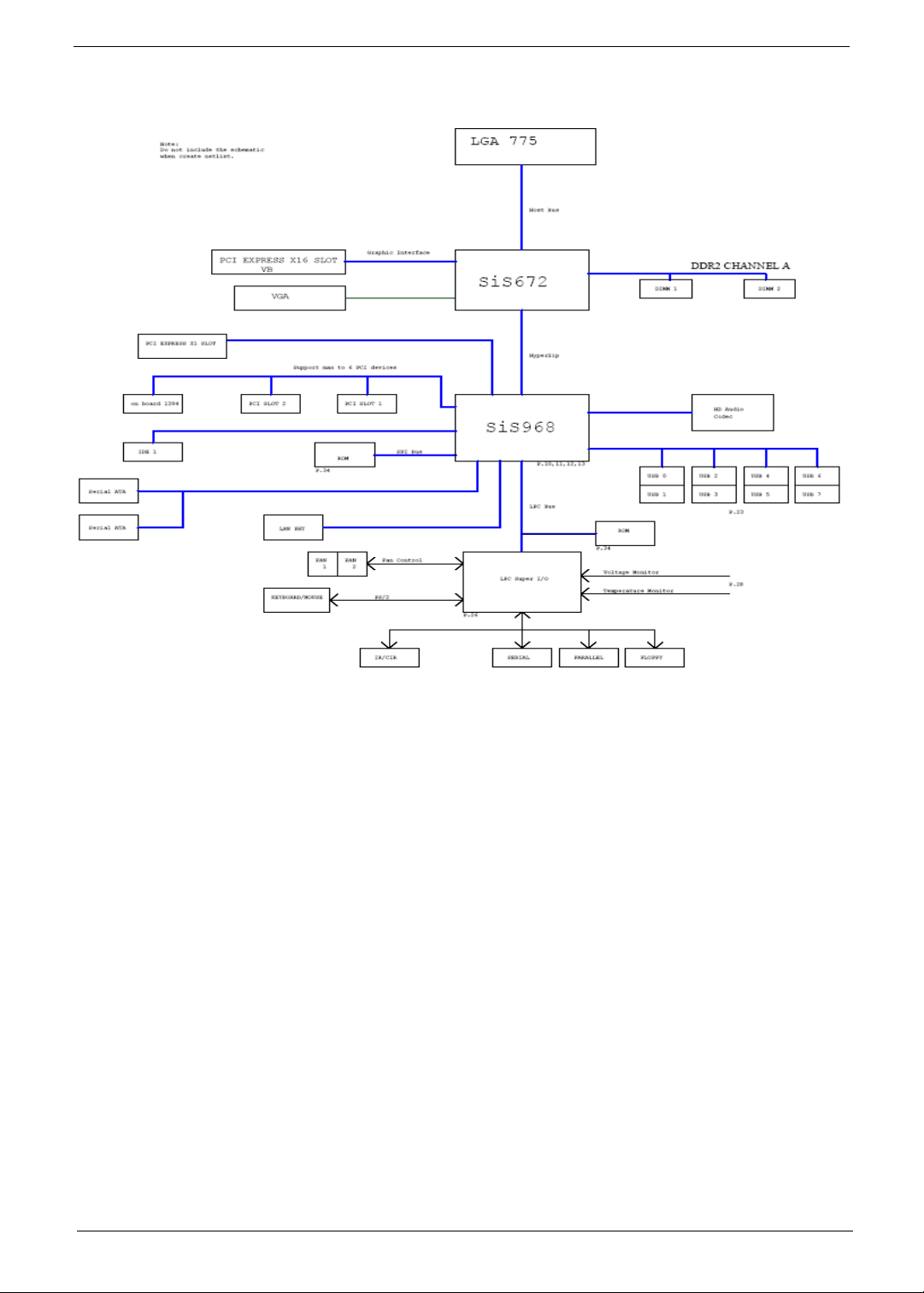
Block Diagram
Chapter 1 5
Page 14
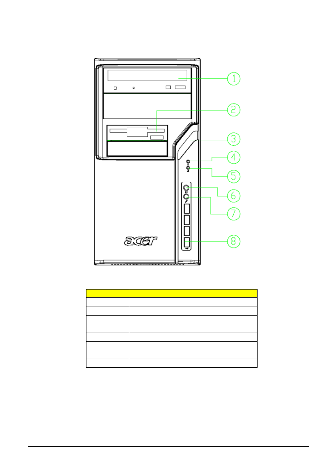
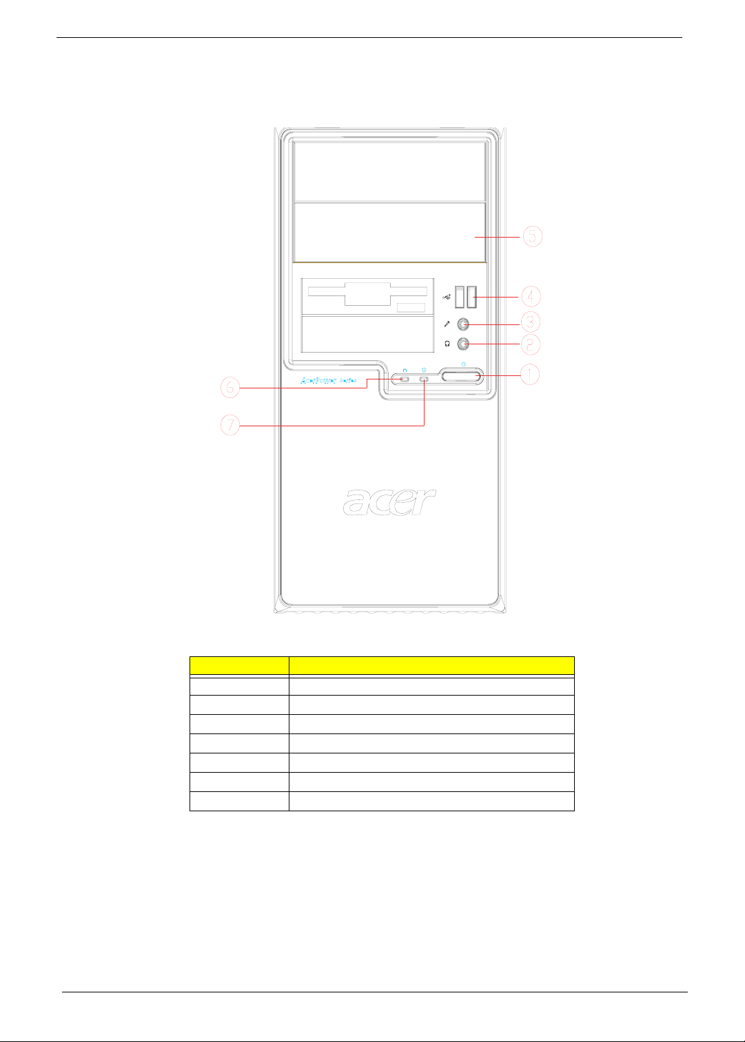
Aspire M1610 Front Panel
The computer’s front panel consists of the following:
Label Description
1 Optical Device
2 3.5 inch Device
3 Power button
4 HDD LED
5LAN LED
6 Speaker Out
7 Microphone
8USB Port
6 Chapter 1
Page 15
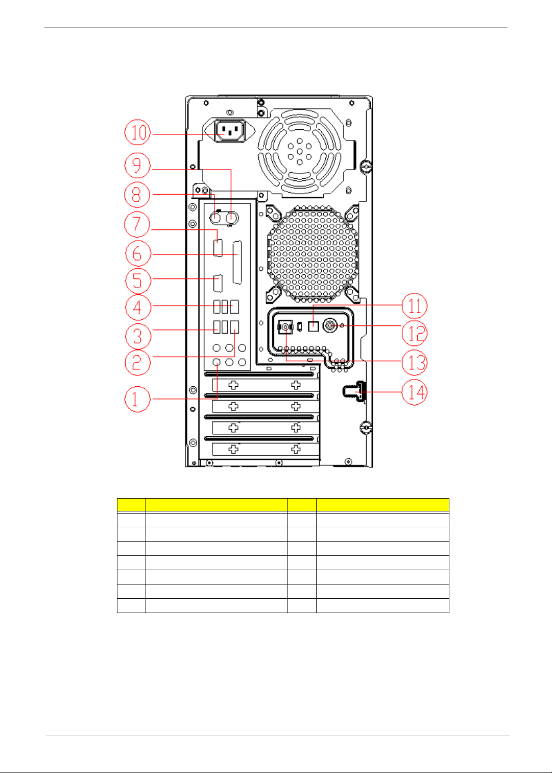
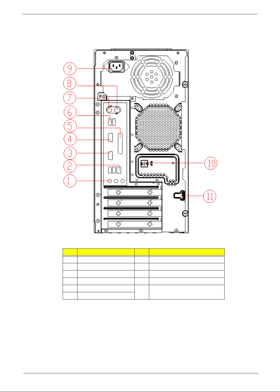
Aspire M1610 Rear Panel
The computer’s rear panel consists of the following:
Label Description Label Description
1 6 audio jacks (7.1 HD audio jack) 2 LAN Port
3 USB PORTS 4 1394 Port
5 CRT/LCD port 6 Parallel port
7 COM port 8 PS/2 keyboard
9 PS/2 mouse 10 Power cord Port
11 SPDIF Bracket 12 SPDIF Port
13 Recovery Switch Holder 14 Lock Handle
Chapter 1 7
Page 16
Veriton M261 Front Panel
The computer’s front panel consists of the following:
Label Description
1 Power-Button
2 Speaker-out/Line-out Port
3 Microphone-in out (Front)
4 USB Ports
5 Optical drive
6 HDD LED
7 Power LED
8 Chapter 1
Page 17
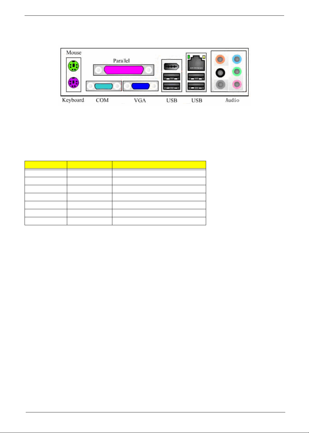
Veriton M261 Rear Panel
The computer’s rear panel consists of the following:
Label Description Label Description
1 3 audio jacks 2 RJ45 port
3 CRT/LCD port 4 Serial port
5 Parallel port 6 USB PORTS
7 PS/2 keyboard 8 PS/2 mouse
9 Power cord Port 10 Recovery Switch Holder
11 Lock Handle
Chapter 1 9
Page 18

Hardware Specifications and Configurations
Processor Support
• Intel Core 2 Duo 755 FSB 800/533 MHz
• Intel Pentium 4/D 775 FSB 800/533 MHz
• Intel Celeron/Celeron D 775 FSB 800/533MHz
System Memory Interface
Single Channel Memory Controller
• Supports DDR2-667/533/400
• Supports two DIMMs
• Up to 1GB per DIMM with maximum memory size up to 2GB
• Supports Single Channel 64 bit mode with maximum memory bandwidth of 5.3GB/s (DDR2-667).
• Supports un-buffered DIMMs only.
• Supports up to 8 banks for DDR2 devices
• Supports 256Mb, 512Mb and 1Gb device technologies for x8 and x16 DDR2 devices
• Supports DDR2 CAS Latency at options of 3, 4 & 5 clocks.
• Support Dynamic Power Down Mode
• Support On-Die-Termination for DDR2
• Support Differential DQS Pair
System Clock
All clocks are generated by 671FX and CLK GEN(ICS9LPR600CGLF-T) including:
Item Clock Speed
Host 133/200/266MHz (System Bus 533/800MHZ)
Memory system DDR2: 400/533/667 MHz,
PCI 33 MHz
PCI Express 100 MHz
USB 12 MHz
1394 33MHz
SIO 33,48 MHz
968 14.318, 25, 33, 48, and 100 MHz
RTC 32.768 KHz
LAN 25MHz
Audio Codec 24 MHz
SIS672 Chipset
SIS672 Host/Memory Controller
SIS 672 is a Host/Memory Controller designed for use with a LGA775 (Land Grid Array) Socket T processor.
The SIS672 provides the CPU interface, DDR2 interface, PCI Express interface, and communicates with SiS
968 MuTIOL 1G Media I/O Interface.
Features of the SIS 671FX chipset family board products include:
• 847 ball FC-BGA package
• Single processor support with 533/800 MHz data transfer rate
10 Chapter 1
Page 19

• The smallest memory capacity possible is 128 MB, assuming Single-Channel Mode by using 256-
Mb technology
• Supports high throughput MuTIOL (Multi-Threaded I/O Link)
• PCI-Express x16 Graphics interface
• One 16-lane PCI Express port intended for Graphics attach, fully compliant to the PCI Express
Base Specification revision 1.0a
• On board VGA support with High-performance DX9
Refer to the Intel SIS672 chipset platform Design Specification for more information
SiS 968 MuTIOL 1G Media I/O
The SiS 968 MuTIOL 1G Media I/O is the other main component of the SIS 671FX chipset that integrates
many I/O functions and provides the I/O subsystem with access to the rest of the platform. 968 features on the
SIS 671FX chipset family board products include:
• 570-pin BGA package
• High Performance SiS MuTIOL 1G T echnology Interconnecting SiS North Bridge and South Bridge
Chips
• PCI Local Bus Specification, Revision 2.3-compliant with support for 33 MHz PCI operations
(supports up to seven Req/Gnt pairs)
• Compliant with PCI Express 1.1
• 1-channel Ultra ATA / 100 Bus Master IDE controller
• ACPI Power Management Logic Support
• Integrated serial ATA host controller with independent operation on 2 ports and AHCI support
• Two Independent OHCI USB 1.1 Host Controllers and One EHCI USB 2.0 Host Controller, support
up to eight ports
• Supports Azalia Specification
• Low Pin Count (LPC) interface
• I/O APIC 2.0
Refer to the RS — SiS 968 MuTIOL 1G Media I/O Design Specification for more details
Super I/O — IT8718F
• Meet LPC Spec 1. 0
• Support PS/2 Keyboard & Mouse
• Support up to four 3.5-inch disk drives
• Support two serial ports, one EPP/ECP parallel port
• Support two fans (2 fan speed control, 2 fan speed monitoring inputs)
• Support IrDA 1.0/ASKIR protocol
• Hardware Monitor supported
Audio Sub-Systems — Realtek ALC888SCo-lay ALC888
The SIS 672 chipset family board products will implement integrated audio support using the SiS 968 MuTIOL
1G Media I/O integrated audio controller. The six channel analog CODEC and audio connectors are optionally
supported on the desktop board. The audio sub-system includes:
• AC ‘97 2.3 /Azalia compliant
• Jack sensing supported.
• Realtek ALC888SCo-lay ALC888 CODEC
Chapter 1 11
Page 20

• Audio Connectors/Headers
• ATAPI analog line-level stereo outputs for Internal Speaker
• Vertical connector for three mini-audio jacks (Stereo Line In, Stereo LINE Out, Stereo Microphone
In)
• Header for Stereo Line out and Mono Microphone In for front panel cabling option that adheres to
the Intel® Front Panel I/O Connectivity Design Gui de
LAN — Realtek821 1BL(default) co-lay 8201CL phy
• Integrated 10/100/1000BASE-T transceiver
• Automatic MDI crossover function
• 10/100/1000BASE-T full-duplex/half-duplex MAC
• Support power down mode
• 100-pin LQFP package for 8211BL
• 48-PQFP package for 8201CL
Universal Serial Bus
• 8 USB 2.0 ports support
• Dual stack with RJ-45 back panel connector
• Dual stack with 1394 connector in rear side
• 2 header supporting 2 USB ports for front panel cabling
TSB43AB23PDTG4 Host Controller
• Fully compliant with provisions of IEEE Std 1394-1995 for a high-performance serial bus and IEEE
Std 1394a-2000
• Fully interoperable with FireWire and i.LINK implementations of IEEE Std 1394
• Three IEEE Std 1394a- 2000 fully compliant cable ports at 100M bits/s, 200M bits/s, and 400M
bits/s
• Two general-purpose I/Os
• PHY-link logic performs system initialization and arbitration functions
• Serial ROM interface supports 2-wire serial EEPROM devices
Expansion Slots
• 1 PCI Express x16 Graphics slot support
• 1 PCI Express x1 Graphics slot support
• 2 PCI Local Bus slots Compliant with PCI rev2.3 specification
Back Panel I/O
This product must follow the Standard I/O Shield Template version 1.00. The back
panel I/O consists of the following:
• Dual stack PS/2 KB/MOUSE
• Parallel port
• Serial port
• VGA port
• Dual stack USB ports with 1394 connector
• Dual Stack USB ports with RJ-45 connector
12 Chapter 1
Page 21
• High Definition Audio 6 Ports Connector with Line In, Line Out, Microphone, Surround, CEN/LFE
and Side-Surround Vertical Audio connector with Line In, Line Out and Microphone
Power & Power Management
Two power management modes are supported in BIOS: Advanced Configuration and Power Interface (ACPI
2.0) or Advanced Power Management (APM 1.2).
• Supports single power/sleep button user model
• OS can turn system off (Soft Off feature)
Wake-Up Event From ACPI State Comments
Power button S1, S3, *S4, S5 -BIOS setting
RTC alarm S1, S3, *S4, S5 -BIOS setting
LAN S1, S3, *S4, S5 -BIOS setting
USB S1, S3 -BIOS setting
PCI S1, S3, *S4, S5 via #PME signal
PS/2 S1, S3 -BIOS se tting
Serial port S1, S3, *S4, S5 -S4 and S5 support External Modem only
• Suspend all devices that support power down modes
• Fan speeds = On/Off
• Support ACPI S0, S1, S3, & S5 System States
*S4 implies OS support only (WinME, Win2000, WinXP)
Hardware Monitor Function
The Super I/O (ITE IT8718F) support Hardware Monitor function in below features.
• VID0-VID7 input pins for CPU Vcore identification
• Built in 8-bit Analog to Digital Converter.
• 2 thermal inputs from optionally remote thermistors or 2N3904 transistors or Pentium 4 thermal
diode output
• 6 external voltage detect inputs
• 9 intrinsic voltage monitoring (typical for Vbat, +5VSB, +5VCC)
• 2 fan speed monitoring inputs
• 2 fan speed control (DC analog output)
• WATCHDOG comparison of all monitored items
• SST/PECI/AMDSII/F Support.
Chapter 1 13
Page 22

System BIOS
LPC Bus
The SST 49LF004B FWH or supported alternative LPCs will be implemented on the GDM03. Refer to the
BIOS Specification for specific implementations.
• Pm49FL004T-33JCE
• 4Mbit symmetrical Flash
SPI Bus (default)
• W25X40VAIZ
• 4Mbit symmetrical Flash
14 Chapter 1
Page 23

Chapter 2
System Utilities
Most systems are already configured by the manufacturer or the dealer. There is no need to run
Setup when starting the computer unless you get a Run Setup message.
The Setup program loads configuration values into the battery-backed nonvolatile memory called CMOS RAM.
This memory area is not part of the system RAM.
NOTE: If you repeatedly receive Run Setup messages, the battery may be bad/flat. In this case, the system
cannot retain configuration values in CMOS.
Before you run Setup, make sure that you have saved all open files. The system reboots immediately after you
exit Setup.
Chapter 2 15
Page 24
Entering Setup
Power on the computer and the system will start POST (Power On Self Test) process. When the message of
“Press DEL to enter SETUP” appears on the screen, press the key of [Delete] to enter the setup menu.
NOTE: If the message disappears before you respond and you still wish to enter Setup, restart the system by
turning it OFF and On. You may also restart the system by simultaneously pressing [Ctrl+Alt+Delete].
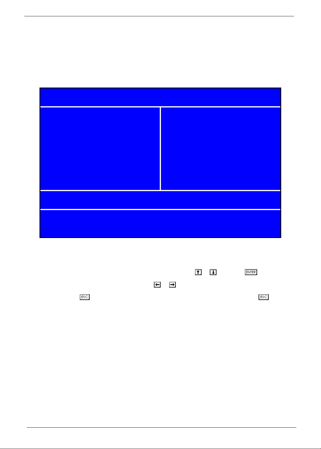
The Setup Utility main menu then appears:
Phoenix - AwardBIOS CMOS Setup Utility
X
Product Information
X
Standard CMOS Features
X
Advanced BIOS Features Load Optimized Defaults
X
Advanced Chipset Features Set Supervisor Password
X
Integrated Peripherals Set User Password
X
Power Management Setup Save & Exit Setup
X
PnP/PCI Configuration Exit Without Saving
Esc: Quit
X
PC Health Status
X
Frequency/Voltage Control
KLIJ
: Select Item
F10: Save & Exit Setup
Change/Set/Disable Password
V02.54 (C) Copyright 1985-2004, American Megatrends, Inc.
The command line at the bottom of the menu tells you how to move within a screen and from one screen to
another.
• To select an option, move the highlight bar by pressing or then press .
• To change a parameter setting, press or until the desired setting is found.
• Press to return to the main menu. If you are already in the main menu, press again to
exit Setup.
The parameters on the screens show default values. These values may not be the same as those in your
system.
The grayed items on the screens have fixed settings and are not user-configured.
NOTE: Due to the application of a new version of BIOS Setup program, you may find the BIOS menu is largely
different from the former models. However, you will soon find out that this version is much more
compact than the former ones.
16 Chapter 2
Page 25

The items in the main menu are explained below:
• Product Information — To introduce the Product Name, System P/N and MainBoard ID...etc.
• Standard CMOS Features — The basic system configuration can be set up through this menu.
• Advanced BIOS Features — The advanced system features can be set up through this menu.
• Advanced Chipset Features — The values for the chipset can be changed through this menu,
and the system performance can be optimized.
• Integrated Peripherals — All onboard peripherals can be set up through this menu.
• Power Management Setup — All the items of Green function features can be set up through this
menu.
• PnP/PCI Configurations — The system’s PnP/PCI settings and parameters can be modified
through this menu.
• PC Health Status — This will display the current status of your PC.
• Frequency/Volt age Control — Frequency and voltage settings can be loaded through this menu.
• Load Default Settings — These parameter settings can be loaded through this menu, however,
the stable default values may be affected.
• Set Supervisor/User Password — The supervisor/user password can be set up through this
menu.
• Save & Exit Setup — Save CMOS value settings to CMOS and exit setup.
• Exit Without Saving — Abandon all CMOS value changes and exit setup.
Chapter 2 17
Page 26

Product Information
The screen below appears if you select Product Information from the main menu:
The Product Information menu contains general data about the system, such as the product name, serial
number, BIOS version, etc. These information is necessary for troubleshooting (maybe required when
asking for technical support).
Phoeni x - A wardB IOS CMOS Set up Utili ty
Pr o d u ct Inform a tio n
Product Name ASM1610/VTM261
Mainboard ID F672CR
System S/N Menu Level
Mainboard S/N 000000000037
System Manufacturer Name Acer
MB Manufacturer Name Acer
System BIOS Version 6.00PG
SMBIOS Version 2.4
System BIOS ID 756A1D01
BIOS Release Date 06/01/2007
It em Help
X
:Move Enter: Select +/-/PU/PD :Value F10: Save and Exit ESC:Exit
KLIJ
F1: General Help F5: Previous Values F7: Optimized Defaults
The following table describes the parameters found in this menu:
Parameter Description
Product Name Displays the model name of your system.
Main Board ID Displays the main board’s identification number.
System S/N Displays your system’s serial number.
Main Board S/N Displays your main board’s serial number.
System Manufacturer Name Displays the manufacturer of your system.
System BIOS Version Specifies the version of your BIOS utility.
SMBIOS version The System Management Interface (SM) BIOS allows you to check your system
System BIOS ID Displays system BIOS identification number.
BIOS Release Date Displays the BIOS latest release date.
18 Chapter 2
hardware components without actually opening your system. Hardware checking
is done via software during start up. This parameter specifies the version of the
SMBIOS utility installed in your system.
Page 27

St andard CMOS Features
Select Standard CMOS Features from the main menu to configure some basic parameters in your system.
The following screen shows the Standard CMOS Features menu:
Phoeni x - AwardBIOS CMOS Setup Utility
Standard CMOS Fea tures
Date (mm:dd:yy) Thu, Apr 12 2007
Time (hh:mm:ss) 10 : 32 : 39
IDE Channel 0 Master [None] Change the day, month,
X
IDE Channel 0 S lave [None] year and cent u ry.
X
IDE Channel 1 Master [None]
X
IDE Channel 1 S lave [None]
X
SATA Channel 1 Master [ST3320820AS]
X
SATA Channel 2 Master [HL-DT-STDVD-RAM GSA-]
X
Drive A None
Ite m Hel p
Menu Level
X
Video [EGA/VGA]
Halt On [All, But Keyboard]
Base Memory 640K
Extended Memory 2096128K
Total Memory 2097152K
:Move Enter: Select +/-/PU/PD :Value F10: Save and Exit ESC:Exit
KLIJ
F1: General Help F5: Previous Values F7: Optimized Defaults
The following table describes the parameters found in this menu. Settings in boldface are the default and
suggested settings.
Parameter Description Options
Date Lets you set the date following the weekday-
month-day-year format
Time Lets you set the time following the hour-minute-
second format
Weekday: Sun, Mon...Sat
Month: Jan., Feb...Dec.
Day: 1 to 31
Year: 1999 to 2098
Hour: 0 to 23
Minute: 0 to 59
Second: 0 to 59
Chapter 2 19
Page 28

Parameter Description Options
IDE Channel 0/1 Master/Slave Leave this item at Auto to enable the system to
automatically detect and configure IDE devices
on the channel. If it fails to find a device, change
the value to Manual and then manually configure
the drive by entering the characteristics of the
drive in the items described below. Please noted
that if you choose IDE Channel 2/3 Master, the
item may change to Extended IDE Drive.
See “IDE Channel 0/1 Master” on page 21 and
“IDE Channel 0/1 Slave” on page 22 for more
information.
SATA Channel 1/2 Master This item display the status of auto detection of
SATA devices. See “SATA Channel 1/2 Master”
on page 23 for more information.
Drive A Allows you to configure your floppy drive A. None
Video This item specifies the type of video card in use.
The default setting is VGA/EGA. Since current
PCs use VGA only, this function is almost
useless and may be disregarded in the future.
Halt On This parameter enables you to control the
system stops in case of Power On Self Test
errors (POST).
Base Memory Refers to the option of memory that is available
to standard DOS programs. DOS systems have
an address space od 1MB, but the top 384KB
(called high memory) is reserved for system use.
This leaves 640 KB of conventional memory.
Everything above 1MB is either extended or
extended memory.
Extended Memory Memory above and beyond the standard 1MB of
base memory that DOS supports. Extended
memory is only available in PCs with an Intel
80286 or later microprocessor. Extended
memory is not configured in any special manner
and is therefore unavailable to most DOS
programs. However, MS Windows and OS/2 can
use extended memory.
T otal Memory Total based and extended memory , and I/O ROM
384KB available to the system.
IDE Device Model Number:
None
SATA Device Model Number:
None
360 KB, 5.25-inch
1.2 MB, 5.25-inch
720 KB, 3.5-inch
1.44M, 3.5 - inch
2.88 MB, 3.5-inch
VGA/EGA
CGA40
CGA80
Mono
All Errors
No Errors
All, but Keyboard
All, but Diskette
All, by Disk/Key
The BIOS POST will determine
the amount of base (or
conventional) memory installed
in the system.
The BIOS determines how much
extended memory is present
during the POST.
total memory of the system.
20 Chapter 2
Page 29

IDE Channel 0/1 Master
The following screen shows the IDE Channel Master menu.
NOTE: IDE Channel 0 and Channel 1 Master have the same options, the only difference is the menu title.
Phoenix - AwardBIOS CMOS Setup Utility
IDE Channel 0 Master
IDE HDD Auto Detection [Press Enter]
Item Help
IDE Channel 0 Master [Auto] Menu Level
Access Mode [Auto]
Capacity 0 MB
Cylinder 0
Head 0
Precomp 0
Landing Zone 0
Sector 0
KLIJ
:Move Enter: Select +/-/PU/PD :Value F10: Save and Exit ESC:Exit
F1: General Help F5: Previous Values F7: Optimized Defaults
XX
Chapter 2 21
Page 30

IDE Channel 0/1 Slave
The following screen shows the IDE Channel Slave menu.
NOTE: IDE Channel 0 and Channel 1 Slave have the same options, the only difference is the menu title.
Phoenix - AwardBIOS CMOS Setup Utility
IDE Channel 0 Slave
IDE Auto Detection [Press Enter]
Item Help
Extended IDE Drive [Auto] Menu Level
Access Mode [Auto]
Capacity 320 MB
Cylinder 0
Head 0
Precomp 0
Landing Zone 0
Sector 0
KLIJ
:Move Enter: Select +/-/PU/PD :Value F10: Save and Exit ESC:Exit
F1: General Help F5: Previous Values F7: Optimized Defaults
XX
22 Chapter 2
Page 31

SATA Channel 1/2 Master
The following screen shows the SATA Channel Master menu.
NOTE: SATA Channel 1 and Channel 2 Master have the same options, the only difference is the menu title.
Phoenix - AwardBIOS CMOS Setup Uti lity
IDE Channel 1 Master
IDE HDD Auto Detection [Pre ss Enter]
Ite m Help
IDE Channel 0 Master [Auto] Menu Level
Access Mode [Auto]
Capacity 0 MB
Cylind er 6553 5
Head 16
Precomp 0
Landing Zone 65534
Sector 255
:Move Enter: Select +/-/PU/PD :Value F10: Save and Exit ESC:Exit
KLIJ
F1: General Help F5: Previous Values F7: Optimized Defaults
XX
Chapter 2 23
Page 32

Advanced BIOS Features
The following screen shows the Advanced BIOS Features:
Phoeni x - AwardBIOS CMOS Setup Utili ty
Advanc ed BIOS Features
CPU Feature [Press Enter]
X
Hard Disk Boot Priority [Press Enter] Menu Level
X
Virus Warning [Disabled]
Quick Power On Self Test [Enabled]
First Boot Device [Hard Disk]
Se co n d B o o t Devi ce [CDRO M]
Third Boot Device [LAN]
Boot Other Device [Enabled]
Boot Up Floppy Seek [Disabled]
Boot Up Num Lock Status [On]
Typematic Rate Setting [Disabled]
X Typematic Rate (chars/sec) 6
X Typematic Delay (Msec) 250
Security Option [Setup]
APIC Mode [Enabled]
MPS Version Control For OS [1.4]
OS Select For DRAM > 64MB [Non-OS2]
HDD S.M.A.R.T. Ca pability [Disab led ]
Report No FDD For Win 95 [No]
Silent Boot [Enabled]
Small Logo (EPA) Show [Disabled]
Configuration Table [Disabled]
Ite m Hel p
X
:Move Enter: Select +/-/PU/PD :Value F10: Save and Exit ESC:Exit
KLIJ
F1: General Help F5: Previous Values F7: Optimized Defaults
The following table describes the parameters found in this menu. Settings in boldface are the default and
suggested settings.
Parameter Description Options
CPU Feature Select to display CPU Feature. See “CPU
Feature” on page 26 for more information.
Hard Disk Boot Priority Select Hard Disk Boot Device Priority. See
“Hard Disk Boot Priority” on page 27 for more
information.
Virus Warning Enable this item to detect the virus in POST
mode.
Quick Power On Self Test This parameter speeds up POST by skipping
some items that are normally checked.
24 Chapter 2
Press [Enter]
Press [Enter]
Enabled
Disabled
Enabled
Disabled
Page 33

Parameter Description Options
First /Second/Third Boot
Device
Boot Other Device This parameter allows you to specify the system
Boot Up Floppy Seek Setting to Enabled will make BIOS seek floppy
Boot Up NumLock Status Sets the NumLock status when the system is
Typematic Rate Setting This item is used to enable or disable the
Typematic Rate (Chars/Sec) Use this item to define how many characters per second are generated by a held-down
Typematic Delay (Msec) Use this item to define how many milliseconds
Security Option Specifies the type of BIOS password protection
APIC Mode This field is used to enable or disable the APIC
MPS Version Control For OS This item displays MPS version control for OS. 1.4
OS Select For DRAM >
64MB
HDD S.M.A.R.T Capability The S.M.A.R.T (Self-Monitoring, Analysis, and
Report No FDD For Win 95 This item allows you to set if the BIOS should
Silent Boot Display Full Screen LOGO during POST Enabled
Small Logo (EPA) Show Determines whether the EPA logo appears
Configuration Table Enable the Configuration Table function Enabled
The items allow you to set the sequence of boot
device where BIOS attempts to load the disk
operating system.
boot up search sequence.
drive a: before booting the system.
powered on. Setting to On will turn on the
NumLock key when the system is powered on.
Setting to Off will allows users to use the arrow
keys on the numeric keypad.
typematic rate setting including Typematic Rate
and Typematic Delay.
key.
must elapse before a held-down key begins generating repeat characters.
that is implemented. Setup means that the
password prompt appears only when end users
try to run Setup. System means that a password
prompt appears every time when the computer
is powered on or when end users try to run
Setup.
(Advanced Programmable Interrupt Controller).
Due to compliance with PC2001 design guide,
the system is able to run in APIC mode.
Enabling APIC mode will expand available IRQ
resources from the system.
This item is only required if you have installed
more than 64MB of memory and you are
running the OS/2 operating system.
Reporting Technology) system is a diagnostics
technology that monitors and predicts device
performance.
report the absence of a floppy disk drive to
Windows 95.
during boot up.
Floppy, LS120, Hard Disk, CD-ROM,
ZIP100, USB-FDD, USB-ZIP, LAN,
Disabled (Disable this sequence).
The sequence following the order of
Floppy, HDD and CD-ROM is
recommended.
Enabled
Disabled
Enabled
Disabled
On
Off
Enabled
Disabled
Setup
System
Enabled
Disabled
Non-OS2
OS2
Enabled
Disabled
No
Yes
Disabled
Enabled
Disabled
Disabled
The advanced chipset features setup option is used to change the values of the chipset registers. These
registers control most of the system options in the computer.
NOTE: Change these settings only if you are familiar with the chipset.
Chapter 2 25
Page 34

CPU Feature
The following screen shows the CPU Features menu:
Phoenix - AwardBIOS CMOS Setup Utility
CPU Features
Limit CPUID MaxVal [Disabled]
C1E Function [Auto]
Execute Disable Bit [Enabled] Menu Level
KLIJ
:Move Enter: Select +/-/PU/PD :Value F10: Save and Exit ESC:Exit
F1: General Help F5: Previous Values F7: Optimized Defaults
Item Help
XX
26 Chapter 2
Page 35

Hard Disk Boot Priority
The following screen shows the Hard Disk Boot Priority menu:
Phoenix - AwardBIOS CMOS Setup Utility
Hard Disk Boot Priority
1. Ch2 M. : ST3320820AS
2. Bootable Add-in Cards
KLIJ
:Move Enter: Select +/-/PU/PD :Value F10: Save and Exit ESC:Exit
F1: General Help F5: Previous Values F7: Optimized Defaults
Item Help
Menu Level
Use <K> or <L> to
select a device, then
press <+> to move it
up, or <-> to move it
down the list. Press
<Esc> to exit this
menu.
XX
Chapter 2 27
Page 36

Advanced Chipset Features
The following screen shows the Advanced Chipset Features menu:
Phoenix - AwardBIOS CMOS Setup Utility
Advanced Chipset Features
X
Internal Graphic Control [Press Enter]
Memory Hole at 15M - 16M [Disabled]
KLIJ
:Move Enter: Select +/-/PU/PD :Value F10: Save and Exit ESC:Exit
F1: General Help F5: Previous Values F7: Optimized Defaults
Item Help
Menu Level
X
Parameter Description Option
Internal Graphic Control This submenu is used to set some
parameters of graphics memory controller.
See “Internal Graphic Control” on page 29
for more information.
Memory Hole at 15M-16M In order to improve performance, certain
space in memory is reserved for ISA cards.
This memory must be mapped into the
memory space below 16MB.
[Press Enter]
15-16MB
14-16MB
Disabled
28 Chapter 2
Page 37

Internal Graphic Control
The following screen shows the Internal Graphic Control menu:
Phoenix - AwardBIOS CMOS Setup Utility
Internal Graphic Control
VGA Share Memory Mode [Auto]
X VGA Share Memory Size 256 MB
Graphic Engine Clock 250 MHz Menu Level
Graphic Memory Clock 250 MHz
AGP Aperture Size [64 MB]
KLIJ
:Move Enter: Select +/-/PU/PD :Value F10: Save and Exit ESC:Exit
F1: General Help F5: Previous Values F7: Optimized Defaults
Item Help
XX
Chapter 2 29
Page 38

Integrated Peripherals
The following screen shows the Integrated Peripherals Features:
Phoenix - AwardBIOS CMOS Setup Utility
Integrated Peripherals
X
Onboard IDE Device [Press Enter]
X
Onboard PCI Device [Press Enter]
X
Onboard Super IO Device [Press Enter] Menu Level
KLIJ
:Move Enter: Select +/-/PU/PD :Value F10: Save and Exit ESC:Exit
F1: General Help F5: Previous Values F7: Optimized Defaults
Item Help
X
Parameter Description Option
Onboard IDE Device Use the arrow keys to select your options;
Onboard PCI Device [Press Enter]
Onboard Super IO Device [Press Enter]
press <Enter> key to enter the setup submenu. The menus and options are shown
below.
[Press Enter]
30 Chapter 2
Page 39

Onboard IDE Device
The following screen shows the Onboard IDE Device menu:
Phoenix - AwardBIOS CMOS Setup Utility
Onboard IDE Device
Serial ATA Mode [2P+2S(IDE)]
IDE Primary Master PIO [Auto]
IDE Primary Slave PIO [Auto]
IDE Secondary Master PIO [Auto]
IDE Secondary Slave PIO [Auto]
Primary Master UltraDMA [Auto]
Primary Slave UltraDMA [Auto]
Secondary Master UltraDMA [Auto]
Secondary Slave UltraDMA [Auto]
IDE DMA Transfer Access [Enabled]
KLIJ
:Move Enter: Select +/-/PU/PD :Value F10: Save and Exit ESC:Exit
F1: General Help F5: Previous Values F7: Optimized Defaults
Item Help
Menu Level
XX
Chapter 2 31
Page 40

Onboard PCI Device
The following screen shows the Onboard PCI Device menu:
Phoenix - AwardBIOS CMOS Setup Utility
Onboard PCI Device
USB Controller [Enabled]
USB 2.0 Supports [Enabled]
USB Keyboard Support [Enabled] Menu Level
USB Mouse Support [Enabled]
Azalia Audio Controller [Azalia]
Onboard LAN Controller [Enabled]
Onboard Lan Boot ROM [Enabled]
KLIJ
:Move Enter: Select +/-/PU/PD :Value F10: Save and Exit ESC:Exit
F1: General Help F5: Previous Values F7: Optimized Defaults
Item Help
XX
32 Chapter 2
Page 41

Onboard Super IO Device
The following screen shows the Onboard Super IO Device menu:
Phoenix - AwardBIOS CMOS Setup Utility
Onboard Super IO Device
Onboard FDC Controller [Enabled]
Onboard Serial Port 1 [3F8/IRQ4]
Onboard Serial Port 2 [2F8/IRQ3] Menu Level
UART Mode Select [Normal]
X UR2 Duplex Mode Half
Onboard Parallel Port [378/IRQ7]
ECP Mode Use DMA [3]
KLIJ
:Move Enter: Select +/-/PU/PD :Value F10: Save and Exit ESC:Exit
F1: General Help F5: Previous Values F7: Optimized Defaults
Item Help
XX
Chapter 2 33
Page 42

Power Management
The Power Management menu lets you configure your system to most effectively save energy while operating
in a manner consistent with your own style of computer use.
The following screen shows the Power Management parameters and their default settings:
Phoenix - AwardBIOS CMOS Setup Utility
Power Management Setup
ACPI function [Enabled]
ACPI Suspend Type [S3(STR)]
Video Off in Suspend [Yes] Menu Level
Video Off Method [V/H SYNC+Blank]
MODEM Use IRQ [AUTO]
HDD Power Down [Disabled]
Soft-Off by PWR-BTTN [Delay 4 sec]
PWRON After PWR-Fail [Former-Sts]
Power On By Ring [Disabled]
Wakeup By LAN PME [Disabled]
LAN Remote Wakeup [Disabled]
Wakeup By PME [Disabled]
Wakeup By USB KB/MS [Enabled]
Wakeup By PS2 KB/MS [Enabled]
Resume By Alarm [Disabled]
X Month Alarm NA
X Day of Month Alarm 0
X Time (hh : mm : ss) Alarm 0 : 0 : 0
HPET Support [Enabled]
HPET Mode [32-bit Mode]
Item Help
X
KLIJ
:Move Enter: Select +/-/PU/PD :Value F10: Save and Exit ESC:Exit
F1: General Help F5: Previous Values F7: Optimized Defaults
The following table describes the parameters found in this menu. Settings in boldface are the default and
suggested settings.
Parameter Description Options
ACPI Function This item is to activate the ACPI (Advanced Configuration
and Power Management Interface) Function. If your
operating system is ACPI aware, such as Windows 98SE/
2000/Me, select Enabled.
34 Chapter 2
Enabled
Disabled
Page 43

Parameter Description Options
ACPI Suspend Type This item specifies the power saving modes for ACPI
Video Off in Suspend This option is used to set video mode in suspend status.
Video Off Method This item determines the manner in which the monitor is
Modem Use IRQ This setting names the interrupt request (IRQ) line
HDD Power Down This option is used to define the continuous HDD
Soft-off by PWR-BATTN This option is used to set the power down
PWRON After PWR-Fail This item allow user set the machine power state when
Power On By Ring These items allow users to customize how the system
Wakeup By LAN PME Disabled
LAN Remote Wakeup Disabled
Wakeup By PME Disabled
Wakeup By USB KB/MS Enabled
Wakeup By PS2 KB/MS Enabled
Resume By Alarm When enabled, this item activates the Month, Day, and
HPET Support This item enables or disables support for the High
HPET Mode This item sets the High Precision Event Timer (HPET)
function. S1(POS): The S1 sleep mode is a low power
state. In this state, no system context (CPU or chipset) is
lost and hardware maintains all system context. S3 (STR):
The S3 sleep mode is s power-down state in which power
is supplied only to essential components such as main
memory and wake-capable devices and all system context
is saved to main memory. The information stored in
memory will be used to restore the PC to the previous state
when an wake-up event occurs. S1&S3: Both S1 and S3
will be adopted.
The setting values are Yes and No.
blanked.
V/H SYNC+Blank: This selection will cause the system to
turn off the vertical and horizontal synchronization ports
and write blanks to the video buffer. Blank Screen: This
option only write blanks to the video buffer. DPMS
Supported: Initial display power management signaling.
assigned to the modem (if any) on your system. Activity of
selected IRQ always awakens the system.
idle time before the HDD enters power saving
mode. The setting values are disabled and 1 min
to 15 min.
method. This function is only valid for systems
using an ATX power supply. When ““instant off” is selected,
press the power switch to immediately
turn off power. When “delay 4 sec” is selected, press and
hole the power button for four seconds to turn off power.
connect the AC power. "Always off" means the machine is
always off when power on; "Always on" means the
machine will always power on when connect the AC power;
"Pre-State" means the machine state is the same as the
last state.
behaves in standby mode. The separate items are set to
Enabled or Disabled to determine whether the specified
action wakes up the system.
Time fields. Setting these fields causes the system to
wakeup on the specified date and time.
Precision Event Timer (HPET).
mode.
S1 (POS)
S3 (STR)
S1&S3
Yes
No
Blank Screen
V/H SYNC+Blank
DPMS
Auto
3,4,5,7,9,10,11
Disabled
1,2,3,4,5,6,7,8,9,10,11,1
2,13,14,15 Min
Instant Off
Delay 4 Sec.
Always Off
Always On
Pre-State
Disabled
Disabled
Enabled
Enabled
Disabled
32-bit Mode
64-bit Mode
Chapter 2 35
Page 44

PnP/PCI Configuration
The following screen shows the PnP/PCI Configuration parameters and their default settings:
Phoenix - AwardBIOS CMOS Setup Ut ili ty
PnP /PCI Configurations
PCI/VGA Palette Snoop [Disabled]
Item Help
**PCI Express relative items**
Maximum ASPM Supported [L0s&L1]
Maximum Payload Size [4096]
:Move Enter: Select +/-/PU/PD :Value F10: Save and Exit ESC:Exit
KLIJ
F1: General Help F5: Previous Values F7: Optimized Defaults
Parameter Description Options
PCI/VGA Palette Snoop Disabled - Data read or written by the CPU is
only directed to the PCI VGA device’s palette
registers.
Enabled - Data read or written by the CPU is
directed to both the PCI VGA device’s palette
registers and the ISA VGA device’s palette
registers, permitting the palette registers of both
VGA devices to be identical.
Maximum ASPM Supported This item specifies the maximum ASPM
Maximum Payload Size This item specifies the maximum payload size
supported for the PCI Express function.
for the PCI Express function.
Menu Level
Disabled
Enabled
*If any ISA bus adapter in the
system requires VGA Palette
snooping, the setting must be set
to “Enabled”.
L0s&L1
L0
L0s
L1
4096
X
36 Chapter 2
Page 45

PC Health Status
The following screen shows the PC Health Status parameters and their default settings:
Phoeni x - AwardBIOS CMOS Setup Utili ty
PC Health S tatus
CPU Warning Temperature [70°C/150°F]
CPU Shutdown Temperature [90°C/194°C]
SYS Shutdown Temperature [70°C/150°F] Menu Level
CPU Core Voltage 1.28V
DIMM Volt age 1.77V
+3.3V 11.84V
+5.0V 4.91V
+12V 11.96V
CPU Temperature 21°C
SYS Temperature 36°C
CPU Fan Speed 881 RPM
SYS Fan Speed 919 RPM
Smart FAN Control [Enabled]
Ite m Hel p
X
:Move Enter: Select +/-/PU/PD :Value F10: Save and Exit ESC:Exit
KLIJ
F1: General Help F5: Previous Values F7: Optimized Defaults
The following table describes the parameters found in this menu:
Parameter Description Options
CPU Warning
Temperature
CPU Shutdown Temp. This option is for setting the shutdown temperature level for the processor. When
SYS Shutdown Temp. This option is for setting the shutdown temperature level for the system. When the
CPU Core Voltage to
SYS Fan Speed
Smart FAN Control Enable smart fan control function.
This item lets you select the temperature at which
you want the system to send out a warning
message to the PC speakers of when the
temperature goes beyond either limit.
the processor reaches the temperature you set, the system will be shut down.
system reaches the temperature you set, the ACPI-aware system will be shut down.
These items in light blue show various current system voltage, temperature, and
speed measurements. These items are read only and cannot be altered.
--When the CPU temperature is higher than 65
degrees Celsius, CPU fan will run at full speed.
--The speed of CPU fan will increase linearly
depend on the temperature if the temperature is
more than 41 degree and less than 65 degree.
--When the CPU temperature is lower than 40
degrees Celsius, CPU fan will be disable.
Disabled
Enabled
Disabled
Chapter 2 37
Page 46

Frequency/Voltage Control
The following screen shows the Frequency and Voltage Control parameters and their default settings:
Phoenix - AwardBIOS CMOS Setup Utility
Frequency/Voltage Control
Auto Detect DIMM/PCI Clk [Enabled]
Spread Spectrum [Disabled]
KLIJ
:Move Enter: Select +/-/PU/PD :Value F10: Save and Exit ESC:Exit
F1: General Help F5: Previous Values F7: Optimized Defaults
Item Help
Menu Level
X
The following table describes the parameters found in this menu. Settings in boldface are the default and
suggested settings.
Parameter Description Options
Auto Detect DIMM/PCI Clk This option allows you to enable/disable the
feature of auto detecting the clock frequency of
the installed PCI bus.
Spread Spectrum When the motherboard’s clock generator pulses,
the extreme values (spikes) of the pulses creates
EMI (Electromagnetic Interference). The spread
Spectrum function reduces the EMI generated by
modulating the pulses so that the spikes of the
pulses are reduced to flatter curves. If you do not
have any EMI problem, leave the setting at
Disabled for optimal system stability and
performance. But if you are plagued by EMI,
setting to Enabled for EMI reduction. Remember
to disable Spread Spectrum if you are
overlocking because even a slight jitter can
introduce a temporary boost in clockspeed which
may just cause your overlock ed processor to
lock up.
Enabled
Disabled
Enabled
38 Chapter 2
Page 47

Load Optimized Defaults
This option opens a dialog box that lets you install defaults for all appropriate items in the Setup Utility.
Phoenix - AwardBIOS CMOS Setup Utility
X
Product Information
X
Standard CMOS Features
X
Advanced BIOS Features Load Optimized Defaults
X
Advanced Chipset Features Set Supervisor Password
X
Integrated Peripherals Set User Password
X
Power Management Setup Save & Exit Setup
X
PnP/PCI Configuration Exit Without Saving
Esc: Quit
X
PC Health Status
X
Frequency/Voltage Control
KLIJ
: Select Item
F10: Save & Exit Setup
Load Optimized Defaults
V02.54 (C) Copyright 1985-2004, American Megatrends, Inc.
Press <Y> and then <Enter> to install the defaults. Press <N> and then <Enter> to not install the defaults. The
defaults place demands on the system that may be greater than the performance level of the components,
such as the CPU and the memory. You can cause fatal errors or instability if you install the optimized defaults
when your hardware does not support them. If you only want to install setup defaults for a specific opti on,
select and display that option.
Chapter 2 39
Page 48

Set Supervisor/User Password
When this function is selected, the following message appears at the center of the screen to assist you in
creating a password.
Phoenix - AwardBIOS CMOS Setup Utility
X
Product Information
X
Standard CMOS Features
X
Advanced BIOS Features Load Optimized Defaults
X
Advanced Chipset Features Set Supervisor Password
X
Integrated Peripherals Set User Password
X
Power Management Setup Save & Exit Setup
X
PnP/PCI Configuration Exit Without Saving
Esc: Quit
X
PC Health Status
X
Frequency/Voltage Control
KLIJ
: Select Item
F10: Save & Exit Setup
Change/Set/Disable Password
V02.54 (C) Copyright 1985-2004, American Megatrends, Inc.
Type the password, up to eight characters, and press <Enter>. The password typed now will clear any
previously entered password from CMOS memory. You will be asked to confirm the password. Type the
password again and press <Enter>. You may also press <Esc> to abort the selection.
To disable password, just press <Enter> when you are prompted to enter password. A message will confirm
the password being disabled. Once the password is disabled, the system will boot and you can enter BIOS
Setup freely.
Supervisor Password has higher priority than User Password. You can use Supervisor Password when
booting the system or entering BIOS Setup to modify all settings. Also you can use User Password when
booting the system or entering BIOS Setup but can not modify any setting if Supervisor Password is enabled
40 Chapter 2
Page 49

Save & Exit Setup
Highlight this item and press <Enter> to save the changes that you have made in the Setup Utility and exit the
Setup Utility.
Phoenix - AwardBIOS CMOS Setup Utility
X
Product Information
X
Standard CMOS Features
X
Advanced BIOS Features Load Optimized Defaults
X
Advanced Chipset Features Set Supervisor Password
X
Integrated Peripherals Set User Password
X
Power Management Setup Save & Exit Setup
X
PnP/PCI Configuration Exit Without Saving
Esc: Quit
X
PC Health Status
X
Frequency/Voltage Control
KLIJ
: Select Item
F10: Save & Exit Setup
Save Data to CMOS
V02.54 (C) Copyright 1985-2004, American Megatrends, Inc.
When the Save and Exit dialog box appears, press <Y> to save and exit, or press <N> to return to the main
menu.
Chapter 2 41
Page 50

Exit Without Saving
Highlight this item and press <Enter> to discard any changes that you have made in the Setup Utility and exit
the Setup Utility.
Phoenix - AwardBIOS CMOS Setup Utility
X
Product Information
X
Standard CMOS Features
X
Advanced BIOS Features Load Optimized Defaults
X
Advanced Chipset Features Set Supervisor Password
X
Integrated Peripherals Set User Password
X
Power Management Setup Save & Exit Setup
X
PnP/PCI Configuration Exit Without Saving
Esc: Quit
X
PC Health Status
X
Frequency/Voltage Control
KLIJ
: Select Item
F10: Save & Exit Setup
Abandon All Data
V02.54 (C) Copyright 1985-2004, American Megatrends, Inc.
When the Exit Without Saving dialog box appears, press <Y> to discard changes and exit, or press <N> to
return to the main menu.
NOTE: If you have made settings that you do not want to save, use the "Exit Without Saving" item and press
<Y> to discard any changes you have made.
42 Chapter 2
Page 51

Machine Disassembly and Replacement
To disassemble the computer, you need the following tools:
• Wrist grounding strap and conductive mat for preventing electrostatic discharge.
• Wire cutter.
• Phillips screwdriver (may require different size).
NOTE: The screws for the different components vary in size. During the disassembly process, group the
screws with the corresponding components to avoid mismatches when putting back the components.
Chapter 3
Chapter 3 43
Page 52

General Information
Before You Begin
Before proceeding with the disassembly procedure, make sure that you do the following:
1. Turn off the power to the system and all peripherals.
2. Unplug the AC adapter and all power and signal cables from the system.
44 Chapter 3
Page 53

Disassembly Procedure
This section tells you how to disassemble the system when you need to perform system service. Please also
refer to the disassembly video, if available.
CAUTION: Before you proceed, make sure you have turned off the system and all peripherals connected to it.
Aspire M1610/V eriton M261 Disassembly
NOTE: The only physical difference between the two models is the front bezel as shown in the procedures.
1. Place the system unit on a flat, steady surface.
Aspire M1610
2. Release the Lock-handle then slide the left side door out.
3. Disconnect the VGA&TV&MODEM card.
Veriton M261
Chapter 3 45
Page 54

4. Disconnect the front bezel LED cable.
5. Disconnect the audio cables.
6. Disconnect the USB cable.
7. Disconnect the Card Reader cable.
46 Chapter 3
Page 55

8. Disconnect the PA and PD power-cable from the MB connector.
9. Disconnect P1 power cable and FDD data cable.
10. Disconnect the ODD power and data cables.
Chapter 3 47
Page 56

11. Disconnect the HDD power and data cables.
12. Disconnect the System Fan power-cable from the MB connector.
13. Disconnect the HDD by railing the HDD-holder as shown. Remove the HDD from the chassis.
48 Chapter 3
Page 57

14. Release the three latches on the front bezel, then remove the front bezel.
Aspire M1610
Front Bezel
15. Disconnect the ODD by railing the ODD-holder as shown below. Remove the ODD from the chassis.
16. Release the CPU cooler from the MB by removing the four securing screws.
Veriton M261
Front Bezel
Chapter 3 49
Page 58

17. Disconnect the CPU Cooler power-cable from the MB connector.
18. Release the memory.
19. Remove the System FAN by releasing the four screws shown then removing the fan from the chassis.
50 Chapter 3
Page 59

20. Remove the CPU by releasing the CPU Latch on the Socket and then disconnecting the CPU.
21. Remove the motherboard by releasing the six screws shown then lifting MB clear of the chassis.
22. Remove the power-supply by releasing the four screws shown then lifting the Power-supply clear of the
chassis.
Chapter 3 51
Page 60

Reassembly Procedure
Aspire M1610/V eriton M261 Reassembly
NOTE: The only physical difference between the two models is the front bezel as shown in the procedures.
1. Install the Power-supply by fitting the Power-supply into the chassis, then fasten the four screws shown.
2. Install the mainboard by aligning the I/O connector with the chassis, making sure the M/B VIA hole fits the
oriented STAND OFF on the chassis. Insert the 6 screws to hold the M/B in place as shown.
3. Install the CPU.
52 Chapter 3
Page 61

4. Fit the System Fan into the chassis, then fasten the four screws shown.
5. Install the Memory.
6. Fit the CPU cooler to the MB and fasten four screws shown.
Chapter 3 53
Page 62

7. Connect the CPU Cooler power-cable to the MB connector.
8. Connect the System Fan power-cable to the MB connector.
9. Install the ODD into the chassis and slide the ODD rail to lock it.
10. Install the FDD and slide the FDD rail to lock it.
54 Chapter 3
Page 63

11. Install the front bezel.
Aspire M1610
Front Bezel
12. Install the HDD into the chassis and slide the HDD rail to lock it.
13. Connect the HDD data cable and power-cable to the rear of HDD.
Veriton M261
Front Bezel
Chapter 3 55
Page 64

14. Connect the ODD data cable and power-cable to the rear of ODD.
15. Connect the P1 power-cable and FDD data cable to the MB connector.
16. Connect the PA and PD power-cable to the MB connector.
56 Chapter 3
Page 65

17. Connect the USB cables.
18. Connect the Card Reader cable.
19. Connect the AUDIO cables.
20. Connect the front bezel LED cable.
Chapter 3 57
Page 66

21. Install the TV&VGA&MODEM card.
22. Close the system.
58 Chapter 3
Page 67

Troubleshooting
Please refer to generic troubleshooting guide for troubleshooting information relating to following topics:
• Power-On Self-Test (POST)
• POST Check Points
• POST Error Messages List
• Error Symptoms List
Chapter 4
Chapter 4 59
Page 68

60 Chapter 4
Page 69

Jumper and Connector Information
Mainboard Jumper Locations
Chapter 5
Item Name Description Item Name Description
1 FP1 Front panel header 11 INTR Chassis Intrusion alarm jumper
2 COM2 COM header 12 CPU_FAN CPU fan power header
3 SATA2 SATA data transfer connector 2 13 F_AUDIO Front panel Audio header
4 SATA1 SATA data transfer connector 1 14 SPEAKER Internal speaker header
5 SYS_FAN_1 System fan header (3pin) 15 SPDIF_OUT SPDIF out header
6 IDE1 Parallel ATA IDE channel 16 F_USB1 Front panel USB header 1
7 PWR1 M/B power connector 17 F_USB2 Front panel USB header 2
8 FLOPPY FDD transfer channel 18 CLR_CMOS Clear CMOS jumper
9 J3 GPIO connector 19 PWR2 CPU Power connector
10 J4 GPIO connector
Chapter 5 61
Page 70

Jumper Settings
This section explains how to set jumpers for correct configuration of the mainboard.
Setting Jumpers
Use the motherboard jumpers to set system configuration options. Jumpers with more than one pin are
numbered. When setting the jumpers, ensure that the ju mper caps are placed on the correct pins.
System Board Jumper Setting
Features Default setting
On-board Jumper and
default setting (See Pin
definition for the detail)
CLR_CMOS(PIN2_3)1
& default setting
2-3 : Normal (Default) 1-2 : Clear CMOS
System Board Header Setting
Front Panel
Illustration Pin Signal Name Description
1 5V_SYS Hard disk LED pull-up(330 ohm) to 5V_SYS
2 GPIO_GRN_HDR_R Pull-up(330 ohm) to 5V_SB_SYS and connect to
SIO GPIO
3 HDD_LED_R Hard disk active LED
4 GPIO_YLW_HDR_R Pull-up(330 ohm) to 5V_SB_SYS and connect to
SIO GPIO
5 GND Reset button
6 PSIN Power Button
7 ICH_SYS_RSTJ ICH_SYS_RSTJ
8 GND Ground
9 5V_SYS 5V_SYS
10 KEY Key
1 1 NC Reserved. Do not use
12 5V_SB LAN LED pull-up(330 ohm) to 5V_SB
13 NC Reserved. Do not use
14 LAN_ACTJ Lan active LED
Silk Screen Footprint Schematic Part
FP1 h 2x7mzo10h85 HEADER_2X7_10
Remark (color and
other)
2-3 : Normal (Default)
62 Chapter 5
Page 71

Front USB
Illustration Pin Signal Name Description
1
VREG_FP_USBP
Front Panel USB Power(Ports 0,1)
WR0
2
VREG_FP_USBP
Front Panel USB Power(Ports 0,1)
WR0
3
USB_FP_P0- Front Panel USB Port 0 Negative Signal
4
USB_FP_P1- Front Panel USB Port 1 Negative Signal
5
USB_FP_P0+ Front Panel USB Port 0 Positive Signal
6
USB_FP_P1+ Front Panel USB Port 1 Positive Signal
7
Ground
8
Ground
9
Key
10
Ground
Silk Screen Footprint Schematic Part
F_USB? H2X5MZO9 HEADER_2X5_9
Front Audio
Illustration Pin Signal Name Description
1
MIC2-L Front Panel Microphone input signal
2
AUD_GND Ground used by Analog Audio Circuits
3
MIC2-R Microphone Power
4
AUD_PRESENCE_LFiltered +5V used by Analog Audio Circuits
5
LINE2-R Right Channel Audio signal to Front Panel
6
MIC2-JD Right Channel Audio signal Return from Front
Panel
7
FRONT-IO-SENSE RSVD for future use to control Headphone
Amplifier
8
Key
9
LINE2-L Left Channel Audio signal to Front Panel
10
LINE2-JD Left Channel Audio signal Return from Front
No Pin
Panel
Silk Screen Footprint Schematic Part
F_AUDIO
h2x5mzo8_1h86
HEADER_2X5_8
Chapter 5 63
Page 72

Front 1394
Illustration Pin Signal Name
1
TPA+
2
TPA-
3
Ground
4
Ground
5
TPB+
6
TPB-
7
+12V(Fused)
8
+12V(Fused)
9
Key
10
Ground
Silk Screen Footprint Schematic Part
F_1394
Internal Speaker
Illustration Pin Signal Name
H2X5MZO9
1MONO-L
2 Ground
3MONO-R
4Key
5 Ground
6 Ground
7VCC
HEADER_2X5_9
Silk Screen Footprint Schematic Part
SPEAKER
h2x4mzo4h86
HEADER_2X4_K4
Sys FAN (3pin)
Illustration Pin Signal Name
1 Ground
2FANOUT
3 SIO FAN SPD
4Key
4
Silk Screen Footprint Schematic Part
SYS_FAN_1
64 Chapter 5
FAN3MH100 CONN3(FAN3P)
Page 73

CPU FAN (4pin)
Illustration Pin Signal Name
1 Ground
2 FAN POWER 12V
3 SIO FANSPD
4FANOUT
5Key
5
Silk Screen Footprint Schematic Part
CPU_FAN
HFAN4M_M1 CONN3(FAN4P)
Clear CMOS
Illustration Description Pin Signal Name
3 Pin
1Ground
2 RTCRSTJ (Connect to ICH)
Normal (Default)
Set pin 2 and pin 3 closed
Clear CMOS
Set pin 1 and pin 2 closed
3 3 Connect to VCC_RTC
Silk Screen Footprint Schematic Part
CLR_CMOS
H3M HEADER_1X3
Intruder
Illustration Pin Signal Name
1 INTRUDERJ
2Ground
Silk Screen Foo tp rint Schematic Part
INTR
H2M HEADER_1X2
J3 (for customer Acer requested)
Illustration Pin Signal Name
1AGPIO1
2Ground
Silk Screen Foo tp rint Schematic Part
INTR
H2M HEADER_1X2
Chapter 5 65
Page 74

J4 (for customer Acer requested)
Illustration Pin Signal Name
1AGPIO2
2Ground
Silk Screen Foo tp rint Schematic Part
INTR
SPDIF_OUT
Illustration Pin Signal Name
Silk Screen Footprint Sch ematic Part
SPDIF_OUT
H2M HEADER_1X2
1 5V_SYS
2 KEY
3 SPDIF_OUT
4GND
H4MO2 HEADER_1X4_K2
IRDA
Illustration Pin Signal Name
1
5V_SB
2
IR_26
3
SIO_RSMRSTJ
4
RESETCONJ
5
IR_20
6
IR_27
7
IR_RE
8
IR_21
9
GND
10
KEY
Silk Screen Footprint Schematic Part
IR1 H2X5MZO10 HEADER_2X5_10
66 Chapter 5
Page 75

COM2
Illustration Pin Signal Name
1
NDCDB
2
NSINB
3
NSOUTB
4
NDTRB
5
GND
6
NDSRB
7
NRTSB
8
NCTSB
9
NRIB
10
KEY
Silk Screen Footprint Schematic Part
COM2 H2X5MZO10 Header_2X5_10
Chapter 5 67
Page 76

68 Chapter 5
Page 77

Chapter 6
FRU (Field Replaceable Unit) List
This chapter gives you the FRU (Field Replaceable Unit) listing in global configurations of
Aspire M1610/ Veriton M261. Refer to this chapter whenever ordering for parts to repair or for RMA
(Return Merchandise Authorization).
NOTE: Please note WHEN ORDERING FRU PARTS, that you should check the most up-to-date information
available on your regional web or channel (http://aicsl.acer.com.tw/spl/, if you do not own a specific
account, you can still access the system with guest; guest). For whatever reasons a part number
change is made, it will not be noted in the printed Service Guide. For ACER-AUTHORIZED SERVICE
PROVIDERS, your Acer office may have a DIFFERENT part number code to those given in the FRU list
of this printed Service Guide. You MUST use the local FRU list provided by your regional Acer office to
order FRU parts for repair and service of customer machines.
Chapter 6 69
Page 78

Exploded Diagrams
Aspire M1610
Item Description Item Decription
1 AM10 Main Bezel 10 Power Supply
2 3.25” Cover 11 Fan
3 5.25” Cover 12 PCI Bracket
4 USB Shielding 13 Left Side Door
5 USB PCB-ASM 14 Motherboard
6 FDD Lock Slide 15 HDD Lock Slide
7 CD ROM Lock Slide 16 HDD
8 Chassis 17 3.5” Device
9 Right Side Door 18 CD ROM
70 Chapter 6
Page 79

Veriton M261
Item Description Item Decription
1 3.5” Filler Panel 10 CD ROM Lock Slide
2 5.25” Rotate Cover 11 USB Board
3 V541 Bezel 12 USB Bracket
4CD ROM 13Right Side
5 FDD w/Panel 14 Chassis
6 HDD Disk 15 Power Supply
7 Mothboard 16 Fan
8 HDD Lock Slide 17 PCI Bracket
9 FDD Lock Slide 18 Left Side
Chapter 6 71
Page 80

Parts Lists
The SPL will update later
72 Chapter 6
 Loading...