

Page 1

EFD1000 E5 Dual Electronic Flight Instrument (EFI) Install Manual
EFD1000 E5
Dual Electronic Flight Instrument (EFI)
Installation Manual
April 2019
DOCUMENT # 900-00041-001 PAGE 1-226 REVISION D
© Copyright 2019 Aspen Avionics Inc.
Page 2

EFD1000 E5 Dual Electronic Flight Instrument (EFI) Install Manual
The installer must determine whether the design changes described in this document are
compatible with previously approved modifications.
This installation is not authorized in aircraft with a MTOW exceeding 6000 pounds.
Correct placement of the aircraft instruments is critical to maintain the aircraft
certification. Certain instruments can be removed. More importantly, certain instruments
must not be removed, See Section 4. The existing turn/bank instrument or a backup attitude
indicator must be retained for all installations except Aircraft Limited to VFR, See Section 4.5.
The RSM contains magnetic elements that are sensitive to magnetic fields on the
aircraft. Section 6.9 describes locating the RSM installation. Mounting the RSM over the cabin
can be problematic due to passengers using headsets with magnetic speakers. Exercise the
control cables while validating a location. Consider all the magnetic field variations. A
satisfactory RSM location is part of the Final Check Sheet. Use caution when installing the RSM
connector to avoid damaging the connector or wiring.
The RSM can be damaged if exposed to a magnet. Do not use magnetic tools or magnetic
levels near the RSM.
The EFD1000 E5 does not display Flight Director. The existing flight director indicator will
need to be retained and relocated. See section 4.4.3
Special Notes to the Installer
It is important to review the entire Installation Manual before installing the EFD1000 E5. The following
items are of special note and should be considered for planning and installation.
DOCUMENT # 900-00041-001 PAGE 2-226 REVISION D
© Copyright 2019 Aspen Avionics Inc.
Page 3

EFD1000 E5 Dual Electronic Flight Instrument (EFI) Install Manual
Revisio
Description of Change
ECO
( )
Original Revision
5465
A
Updated manual for initial release to the field
5483
B
Removed Special Conditions for Aircraft Limited to VFR. Clarified regulatory wording and
typographical errors.
5578
C
Corrected the transmit rate for the ARINC 429 outputs. Added a date to the cover. Updated
paragraph 7.2.11 to add tubing.
5588
D
Added Figure 4-1A, “VFR Configuration”. Added Section 4.5, Special Considerations for Aircraft
Limited to VFR. Added Figure 9-4 “VFR Only - No GPS input Configurations” and updated Fig 910 to add VFR config with NAV, no GPS. Added VFR configs to 10.4.6.8. Added step to Appdx B
– Final Check Sheet to verify aircraft is placarded for VFR- if limited to VFR.
5718
Prepared
By:
Tim McNany
Reviewed
By:
Mike Studley /
Penny Heinz
See ECO Record For Release Authorization
DOCUMENT REVISIONS
DOCUMENT # 900-00041-001 PAGE 3-226 REVISION D
© Copyright 2019 Aspen Avionics Inc.
Page 4

EFD1000 E5 Dual Electronic Flight Instrument (EFI) Install Manual
This manual contains FAA Approved installation instructions for installation of the Aspen™ EFD1000 E5
system under the AML STC for use as an electronic flight display during day/night IFR and VFR
operations in those Part 23 Class I and II aircraft (as defined in AC 23.1309-1E) listed on the
AML. Installation of the EFD1000 E5 into part 23 Class I or II aircraft not included in the AML, into any
14 CFR Part 23 Class III or IV aircraft, or into any part 25, 27, or 29 aircraft, or non-U.S. registered
aircraft requires separate airworthiness approval.
This document is protected by the Copyright Laws of the United States and other countries. Nevertheless,
authorized Aspen dealers and distributors are licensed to make a reasonable number of verbatim copies of this
document for use in their business as Aspen dealers.
Reproduction for any other purpose is strictly prohibited.
Public or fee-based copy centers need not inquire into the bearer's status as an Aspen dealer or distributor, into the
purposes for which reproductions are to be made, or into the reasonableness of the number of reproductions
requested.
DOCUMENT # 900-00041-001 PAGE 4-226 REVISION D
© Copyright 2019 Aspen Avionics Inc.
Page 5

EFD1000 E5 Dual Electronic Flight Instrument (EFI) Install Manual
Table of Contents:
LIST OF TABLES ........................................................................................................................... 12
LIST OF FIGURES .......................................................................................................................... 13
LIST OF DEFINITIONS, ACRONYMS, ABBREVIATIONS ...................................................................... 16
1 INTRODUCTION ................................................................................................ 17
1.1 PART NUMBERS .................................................................................................... 17
1.1.1 LATEST APPROVED SOFTWARE VERSIONS ...................................................................... 17
1.1.2 AML-STC DOCUMENT LIST .................................................................................... 18
1.2 INSTALLATION KIT CONTENTS ................................................................................... 18
1.3 OPTIONAL LRU INSTALL KITS ................................................................................... 19
1.4 ACCESSORIES REQUIRED BUT NOT SUPPLIED – EFD1000 E5 ............................................. 20
1.5 OPTIONAL ACCESSORIES NOT SUPPLIED – EFD1000 E5 .................................................. 20
1.6 OPTIONAL ACCESSORIES REQUIRED BUT NOT SUPPLIED – EA100 ....................................... 20
1.7 SPECIAL TOOLS REQUIRED ....................................................................................... 21
1.8 VENDOR INFORMATION ........................................................................................... 21
1.9 WARRANTY REGISTRATION ....................................................................................... 21
1.10 REGULATORY COMPLIANCE ...................................................................................... 21
1.10.1 TECHNICAL STANDARD ORDER ................................................................................. 21
1.10.2 PMA APPROVAL ................................................................................................... 21
1.10.3 SOFTWARE CERTIFICATION ....................................................................................... 22
1.10.4 ENVIRONMENTAL COMPLIANCE .................................................................................. 22
1.10.5 INSTALLATION APPROVAL ........................................................................................ 22
1.11 FIELD REPLACEABLE PARTS ....................................................................................... 22
1.12 RESERVED ........................................................................................................... 22
2 EQUIPMENT SPECIFICATIONS AND LIMITATIONS ................................................. 23
2.1 EFD1000 E5 ...................................................................................................... 23
2.1.1 GENERAL SPECIFICATIONS ........................................................................................ 23
2.1.2 OPERATIONAL SPECIFICATIONS .................................................................................. 23
2.1.3 I/O SPECIFICATIONS .............................................................................................. 23
2.1.4 CERTIFICATION SPECIFICATIONS ................................................................................ 23
2.1.5 EFD1000 E5 OUTLINE DRAWING ............................................................................. 24
2.1.6 DESIGN EYE VIEWING ENVELOPE ................................................................................ 24
2.2 REMOTE SENSOR MODULE (RSM) .............................................................................. 25
2.2.1 GENERAL SPECIFICATIONS ........................................................................................ 25
2.2.2 OPERATIONAL SPECIFICATIONS .................................................................................. 25
2.2.3 I/O SPECIFICATIONS .............................................................................................. 25
2.2.4 CERTIFICATION SPECIFICATIONS ................................................................................ 25
2.2.5 OUTLINE DRAWING: ............................................................................................... 26
2.3 CONFIGURATION MODULE (CM) ................................................................................ 26
2.3.1 GENERAL SPECIFICATIONS ........................................................................................ 26
2.3.2 OPERATIONAL SPECIFICATIONS .................................................................................. 27
2.3.3 I/O SPECIFICATIONS .............................................................................................. 27
2.3.4 CERTIFICATION SPECIFICATIONS ................................................................................ 27
2.3.5 OUTLINE DRAWING ................................................................................................ 27
DOCUMENT # 900-00041-001 PAGE 5-226 REVISION D
© Copyright 2019 Aspen Avionics Inc.
Page 6

EFD1000 E5 Dual Electronic Flight Instrument (EFI) Install Manual
2.4 ANALOG CONVERTER UNIT (ACU) ............................................................................. 28
2.4.1 GENERAL SPECIFICATIONS ........................................................................................ 28
2.4.2 OPERATIONAL SPECIFICATIONS .................................................................................. 28
2.4.3 I/O SPECIFICATIONS .............................................................................................. 28
2.4.4 CERTIFICATION SPECIFICATIONS ................................................................................ 28
2.4.5 OUTLINE DRAWING: ............................................................................................... 29
2.5 ANALOG CONVERTER UNIT 2 ................................................................................... 29
2.5.1 GENERAL SPECIFICATIONS ........................................................................................ 29
2.5.2 OPERATIONAL SPECIFICATIONS .................................................................................. 29
2.5.3 I/O SPECIFICATIONS .............................................................................................. 29
2.5.4 CERTIFICATION SPECIFICATIONS ................................................................................ 30
2.5.5 OUTLINE DRAWING ................................................................................................ 30
3 SYSTEM DESCRIPTION ....................................................................................... 31
3.1 EFD1000 E5 DUAL ELECTRONIC FLIGHT INSTRUMENT (EFI) SYSTEM ................................... 31
3.2 EFD1000 E5 FLIGHT DISPLAY (EFD) ......................................................................... 31
3.3 REMOTE SENSOR MODULE (RSM) .............................................................................. 32
3.4 CONFIGURATION MODULE (CM) ................................................................................ 32
3.5 ANALOG CONVERTER UNIT (ACU) ............................................................................. 32
3.6 ANALOG CONVERTER UNIT 2 (ACU2) ........................................................................ 32
3.7 SYSTEM ARCHITECTURE .......................................................................................... 33
4 STC SPECIFIC REQUIREMENTS AND LIMITATIONS ................................................ 35
4.1 EFD1000 E5 SYSTEM LIMITATIONS ........................................................................... 35
4.2 EA100 INSTALLATION LIMITATIONS (EA100 IS OPTIONAL) .............................................. 35
4.3 AUTHORIZED CONFIGURATIONS ................................................................................. 35
4.4 GENERAL STANDBY INSTRUMENT REQUIREMENTS FOR IFR-CAPABLE AIRPLANES ...................... 38
4.4.1 PNEUMATIC ATTITUDE (EXISTING) .............................................................................. 38
4.4.2 ELECTRIC ATTITUDE (EXISTING) ................................................................................. 38
4.4.3 EXISTING ATTITUDE POSITIONING (IF KEEPING) ............................................................... 38
4.4.4 AIRSPEED AND ALTIMETER ....................................................................................... 40
4.4.5 BACK UP NAV INDICATOR ........................................................................................ 40
4.4.6 PLACARDS ........................................................................................................... 40
4.5 SPECIAL CONSIDERATION FOR AIRPLANES LIMITED TO VFR ............................................... 41
5 PRE-MODIFICATION PLANNING ......................................................................... 42
5.1 PRE-MODIFICATION CHECKLIST ................................................................................ 42
5.1.1 DIRECTIONAL GYRO/ HSI ........................................................................................ 43
5.1.2 AIRCRAFT POWER REQUIREMENTS .............................................................................. 43
5.1.3 EQUIPMENT POWER REQUIREMENTS ............................................................................ 43
5.1.4 RESERVED ........................................................................................................... 43
5.1.5 CESSNA 190/195 SPECIAL CONSIDERATION ................................................................ 44
5.2 RESERVED ........................................................................................................... 44
5.3 CONVENTIONAL LANDING GEAR “TAIL DRAGGER” AIRCRAFT .............................................. 44
5.4 OPTIONAL INTERFACES ........................................................................................... 45
5.4.1 AUTOPILOT ......................................................................................................... 45
5.4.1.1 EA100 ADAPTER .................................................................................................. 45
5.4.2 GPS NAVIGATOR COMPATIBILITY ............................................................................... 46
DOCUMENT # 900-00041-001 PAGE 6-226 REVISION D
© Copyright 2019 Aspen Avionics Inc.
Page 7

EFD1000 E5 Dual Electronic Flight Instrument (EFI) Install Manual
5.4.3 GPSS ................................................................................................................ 46
5.4.4 GPS/ NAV SWITCHING .......................................................................................... 46
5.4.5 HEADING OUTPUT ................................................................................................. 47
5.4.6 AIR DATA OUTPUTS ............................................................................................... 47
5.4.6.1 EFD1000 E5 AS ENCODING ALTITUDE SOURCE ............................................................ 47
5.4.7 FLUSH OR RECESS MOUNTING THE EFD ....................................................................... 48
6 MECHANICAL INSTALLATION ............................................................................. 50
6.1 UNPACKING AND INSPECTING EQUIPMENT ..................................................................... 50
6.2 EQUIPMENT LOCATION DOCUMENTATION ..................................................................... 50
6.3 LOG BOOK ENTRY ................................................................................................. 50
6.4 WEIGHT AND BALANCE ........................................................................................... 50
6.5 MOUNTING LIMITATIONS ......................................................................................... 50
6.5.1 EFD1000 E5 MOUNTING LIMITATIONS (EFD) .............................................................. 51
6.5.2 RSM MOUNTING LIMITATIONS .................................................................................. 51
6.6 EQUIPMENT BONDING ............................................................................................. 51
6.7 COOLING ............................................................................................................ 52
6.8 EFD INSTALLATION ............................................................................................... 52
6.8.1 EFD MOUNTING LOCATION ..................................................................................... 52
6.8.2 SURFACE MOUNTING THE EFD AS PER FIGURE 6-2 ......................................................... 52
6.8.3 RECESS MOUNTING THE EFD AS PER FIGURE 6-4 ........................................................... 54
6.8.3.1 RECESS MOUNT MODIFICATION PROCEDURE ................................................................. 54
6.8.4 EFD BONDING STRAP ............................................................................................. 59
6.8.5 PITOT AND STATIC CONNECTIONS ............................................................................. 59
6.8.6 QUICK CONNECTOR INSTALLATION ............................................................................ 60
6.8.7 LEAK CHECK REQUIREMENTS .................................................................................... 60
6.9 RSM INSTALLATION ............................................................................................... 61
6.9.1 RSM INTERNAL MOUNTING ...................................................................................... 61
6.9.2 RSM INVERTED OR BOTTOM MOUNTING ...................................................................... 61
6.9.3 RSM EXTERNAL TOP MOUNTING ............................................................................... 61
6.9.4 PROPOSED RSM LOCATION CHECK ............................................................................ 65
6.9.5 PRESSURIZED AIRCRAFT ........................................................................................... 67
6.9.6 RSM MOUNTING ON NON-METAL OR DAMAGE-TOLERANT DESIGN AIRCRAFT ....................... 68
6.9.7 RSM MOUNTING ANGLES ........................................................................................ 68
6.9.7.1 LONGITUDINAL AXIS .............................................................................................. 68
6.9.7.2 PITCH AXIS .......................................................................................................... 68
6.9.7.3 ROLL AXIS ........................................................................................................... 69
6.9.8 RSM EXTERNAL MOUNT – ALUMINUM SKIN .................................................................. 70
6.9.8.1 RSM DOUBLER FABRICATION .................................................................................... 70
6.9.9 RSM INTERNAL MOUNT .......................................................................................... 72
6.9.10 RSM INSTALLATION ............................................................................................... 72
6.9.11 RSM SHIM FABRICATION (IF NECESSARY) ...................................................................... 73
6.10 ACU/ACU2 INSTALLATION ..................................................................................... 74
6.10.1 ACU/ACU2 MOUNTING ........................................................................................ 75
6.11 CONFIGURATION MODULE INSTALLATION ..................................................................... 78
7 ELECTRICAL INSTALLATION ............................................................................... 80
DOCUMENT # 900-00041-001 PAGE 7-226 REVISION D
© Copyright 2019 Aspen Avionics Inc.
Page 8

EFD1000 E5 Dual Electronic Flight Instrument (EFI) Install Manual
7.1 ELECTRICAL LOAD ANALYSIS .................................................................................... 80
7.2 ELECTRICAL INSTALLATION ...................................................................................... 80
7.2.1 EFD1000 E5 ...................................................................................................... 80
7.2.2 ACU OR ACU2 (OPTIONAL) ..................................................................................... 80
7.2.3 MISCELLANEOUS WIRING ......................................................................................... 80
7.2.4 HIRF/LIGHTNING REQUIREMENTS .............................................................................. 81
7.2.5 EFD TO GPS/VLOC/ACU WIRING ........................................................................... 81
7.2.6 RSM WIRING ....................................................................................................... 82
7.2.6.1 ASSEMBLY USING ASPEN PREFABRICATED 35FT AND OPTIONAL 50FT CABLES .......................... 82
7.2.6.2 ASSEMBLY USING M27500-A24SD7T23 CABLE ......................................................... 82
7.2.6.3 EFD END ........................................................................................................... 83
7.2.7 CONFIGURATION MODULE WIRING ............................................................................. 83
7.2.8 ACU WIRING ....................................................................................................... 84
7.2.9 BACK UP NAV INDICATOR WIRING ............................................................................. 84
7.2.10 AUTOPILOT WIRING ............................................................................................... 84
7.2.11 BACKUP INSTRUMENT WIRING AND CABLE BUNDLE .......................................................... 84
8 ELECTRICAL CONNECTIONS ............................................................................... 86
8.1 EFD ELECTRICAL SPECIFICATIONS .............................................................................. 86
8.1.1 POWER INPUT ....................................................................................................... 86
8.1.2 RS-232 GPS INPUT .............................................................................................. 86
8.1.3 RS-232 ADC OUTPUT .......................................................................................... 86
8.1.4 ARINC 429 GPS INPUTS ........................................................................................ 86
8.1.5 ARINC 429 VLOC INPUT ...................................................................................... 87
8.1.6 ARINC 429 OUTPUT ............................................................................................ 87
8.2 ACU ELECTRICAL SPECIFICATIONS (910-00004 ALL DASH NUMBERS) ................................ 88
8.2.1 POWER INPUT ....................................................................................................... 88
8.2.2 RESERVED ........................................................................................................... 88
8.2.3 VLOC RECEIVER ................................................................................................... 88
8.2.3.1 NAV COMPOSITE INPUT .......................................................................................... 88
8.2.3.2 ILS ENERGIZE DISCRETE INPUT .................................................................................. 88
8.2.3.3 GLIDE SLOPE DEVIATION INPUT ................................................................................. 88
8.2.3.4 GLIDE SLOPE FLAG INPUT ........................................................................................ 89
8.2.4 GPS RECEIVER ...................................................................................................... 89
8.2.4.1 OBS SINE, COSINE, ROTOR ...................................................................................... 89
8.2.4.2 TO/ FROM FLAG INPUT ........................................................................................ 89
8.2.4.3 LEFT/ RIGHT INPUT ............................................................................................. 89
8.2.4.4 LATERAL FLAG INPUT ............................................................................................. 89
8.2.4.5 VERTICAL DEVIATION INPUT ..................................................................................... 89
8.2.4.6 VERTICAL DEVIATION FLAG INPUT .............................................................................. 89
8.2.4.7 OBS/ LEG (HOLD) INPUT ...................................................................................... 89
8.2.4.8 APPR ACTIVE INPUT .............................................................................................. 90
8.2.4.9 FCS-LOC ENGAGE INPUT ....................................................................................... 90
8.2.5 AUTOPILOT ......................................................................................................... 90
8.2.5.1 LATERAL DEVIATION OUTPUT ................................................................................... 90
8.2.5.2 LATERAL FLAG OUTPUT .......................................................................................... 90
DOCUMENT # 900-00041-001 PAGE 8-226 REVISION D
© Copyright 2019 Aspen Avionics Inc.
Page 9

EFD1000 E5 Dual Electronic Flight Instrument (EFI) Install Manual
8.2.5.3 VERTICAL DEVIATION OUTPUT .................................................................................. 90
8.2.5.4 VERTICAL FLAG OUTPUT ......................................................................................... 90
8.2.5.5 ILS ENERGIZE OUTPUT ............................................................................................ 90
8.2.5.6 VOLT REFERENCE OUTPUT ....................................................................................... 91
8.2.5.7 KI-525A HEADING AND COURSE DATUM OUTPUT ........................................................ 91
8.2.5.8 NSD-360 HEADING AND COURSE DATUM OUTPUT ....................................................... 91
8.2.5.9 PN-101 HEADING AND COURSE DATUM OUTPUT ......................................................... 92
8.2.5.10 HEADING VALID OUTPUT ......................................................................................... 92
8.2.5.11 GPS SELECTED OUTPUT .......................................................................................... 93
8.2.5.12 ARINC 429 OUTPUT ............................................................................................ 93
8.3 ACU2 ELECTRICAL SPECIFICATIONS (910-00004-10X ONLY) ......................................... 93
8.3.1 HEADING SYNCHRO OUT ......................................................................................... 93
8.3.2 +/- 15VDC POWER OUTPUT ................................................................................... 94
8.3.3 GLIDESLOPE FLAG (NARCO) ...................................................................................... 94
8.3.4 ARINC 429 OUTPUT ............................................................................................ 94
8.4 EFD PIN OUT ...................................................................................................... 94
8.5 RSM PIN OUT ...................................................................................................... 96
8.6 CONFIGURATION MODULE PIN OUT ............................................................................ 96
8.7 ACU/ACU2 PIN OUT ............................................................................................ 97
9 INSTALLATION WIRING DIAGRAMS ................................................................... 102
9.1 LIST OF WIRING DIAGRAMS – EFD1000 E5 ............................................................... 102
9.2 OPTIONAL INTERFACES – ACU AND ACU2 ................................................................. 103
10 CONFIGURATION AND EQUIPMENT CHECKOUT ................................................ 134
10.1 WIRING CHECKS .................................................................................................. 134
10.2 BONDING CHECK – 14CFR 23.867(B) ..................................................................... 134
10.3 INITIAL SYSTEM TURN ON ...................................................................................... 134
10.4 SYSTEM CONFIGURATION ....................................................................................... 135
10.4.1 MAIN MENU ACCESS ............................................................................................ 135
10.4.2 MENU NAVIGATION ............................................................................................. 135
10.4.3 EDIT MODE ....................................................................................................... 135
10.4.4 MAIN MENU CONFIGURATION ................................................................................. 135
10.4.5 INSTALLATION MENU – UNIT CONFIGURATION ............................................................. 135
10.4.6 EFD1000 E5 INSTALLATION MENU CONFIGURATION ................................................... 138
INSTALLATION MENU CONFIGURATION – EFD1000 E5 ................................................................ 138
10.4.6.1 INSTALLATION MENU PAGE - IAS CONFIG A ............................................................. 138
10.4.6.2 INSTALLATION MENU PAGE – IAS CONFIG B.............................................................. 140
10.4.6.3 INSTALLATION MENU PAGE – IAS CONFIG C ............................................................. 140
10.4.6.4 INSTALLATION MENU PAGE – IAS CONFIG D ............................................................. 140
10.4.6.5 INSTALLATION MENU PAGE – IAS CONFIG E .............................................................. 140
10.4.6.6 INSTALLATION MENU PAGE - IAS CONFIG F ............................................................. 141
10.4.6.7 INSTALLATION MENU PAGE - IAS CONFIG G ............................................................. 141
10.4.6.8 INSTALLATION MENU PAGE – NAV SETUP A .............................................................. 142
10.4.6.9 INSTALLATION MENU PAGE – NAV SETUP B .............................................................. 142
10.4.6.10 INSTALLATION MENU PAGE – NAV SETUP C .............................................................. 143
10.4.6.11 INSTALLATION MENU PAGE – RS-232 CONFIG A ....................................................... 143
DOCUMENT # 900-00041-001 PAGE 9-226 REVISION D
© Copyright 2019 Aspen Avionics Inc.
Page 10

EFD1000 E5 Dual Electronic Flight Instrument (EFI) Install Manual
10.4.6.12 INSTALLATION MENU PAGE – RS-232 CONFIG B ....................................................... 144
10.4.6.13 INSTALLATION MENU PAGE – RS-232 CONFIG C ....................................................... 144
10.4.6.14 INSTALLATION MENU PAGE – ACU CONFIG A ........................................................... 144
10.4.6.15 INSTALLATION MENU PAGE – ACU CONFIG B ............................................................ 145
10.4.6.16 INSTALLATION MENU PAGE – MISC CONFIG A .......................................................... 145
10.4.6.17 INSTALLATION MENU PAGE – MISC CONFIG B ........................................................... 145
10.4.6.18 INSTALLATION MENU PAGE – MISC CONFIG C .......................................................... 146
10.4.6.19 INSTALLATION MENU PAGE – MISC CONFIG D .......................................................... 146
10.4.6.20 INSTALLATION MENU PAGE – RSM CALIBRATION ...................................................... 146
10.4.6.21 INSTALLATION MENU PAGE – ACCEL BIAS CAL ......................................................... 148
10.4.6.22 INSTALLATION MENU PAGE – WX-500 ..................................................................... 148
10.4.6.23 INSTALLATION MENU PAGE – DFC A/P CONFIG PAGE A ............................................. 148
10.4.6.24 INSTALLATION MENU PAGE – DFC A/P CONFIG PAGE B ............................................. 148
10.4.6.25 INSTALLATION MENU PAGE – AOA CONFIG .............................................................. 148
10.4.6.26 INSTALLATION MENU PAGE – NETWORK PAGE .......................................................... 148
10.4.6.27 INSTALLATION MENU PAGE - DIAGNOSTICS ............................................................ 149
10.4.7 CONFIGURATION DEFINITIONS................................................................................. 149
10.4.7.1 IAS CONFIGURATIONS .......................................................................................... 149
10.4.7.2 PANEL TILT PITCH ADJ ..................................................................................... 150
10.4.7.3 PANEL ROLL ADJ.............................................................................................. 152
10.4.7.4 ATTITUDE REF SYMBOL ADJ ............................................................................. 152
10.4.8 NAV SETUP CONFIGURATION ................................................................................. 152
10.4.8.1 GPS/NAV#1 (ID#1) .......................................................................................... 152
10.4.8.2 COMPOSITE PHASE (VOR1, VOR2) ..................................................................... 152
10.4.9 ACU CONFIGURATION .......................................................................................... 152
10.4.9.1 ACU HSI TYPE.................................................................................................. 152
10.4.9.2 ACU DATUM ................................................................................................... 153
10.4.9.3 EXITING / SAVING DATA .................................................................................. 153
10.5 RSM CALIBRATION .............................................................................................. 153
10.5.1 CALIBRATION OVERVIEW ....................................................................................... 153
10.5.1.1 SECOND PHASE RSM LOCATION EVALUATION ............................................................. 154
10.5.1.2 CONVENTIONAL GEAR RSM CALIBRATION PROCEDURE .................................................. 156
10.5.2 RSM CALIBRATION PROCEDURE .............................................................................. 158
10.5.3 HEADING OFFSET ADJUSTMENT ............................................................................... 160
10.5.3.1 HEADING OFFSET ADJUSTMENT ............................................................................... 160
10.5.4 HEADING ACCURACY TEST ..................................................................................... 161
10.5.5 HEADING INTERFERENCE TEST ................................................................................. 161
10.6 GROUND TEST PROCEDURE .................................................................................... 162
10.6.1 INDICATED AIRSPEED DISPLAY ................................................................................. 162
10.6.2 ALTITUDE DISPLAY .............................................................................................. 163
10.6.3 SYSTEM LEAK TEST .............................................................................................. 163
10.6.4 AHRS SENSOR TEST ............................................................................................ 163
10.6.5 GPS1 SENSOR TEST (LABELED AS GPS1) ................................................................... 163
10.6.5.1 ALL GPS INTERFACES ........................................................................................... 163
10.6.5.2 ANALOG GPS INTERFACES ..................................................................................... 163
DOCUMENT # 900-00041-001 PAGE 10-226 REVISION D
© Copyright 2019 Aspen Avionics Inc.
Page 11

EFD1000 E5 Dual Electronic Flight Instrument (EFI) Install Manual
10.6.6 NAV RECEIVER SENSOR TEST (LABEL AS VLOC1) ......................................................... 164
10.6.7 BACKUP NAVIGATION INDICATOR ............................................................................. 164
10.6.8 AUTOPILOT SENSOR TEST ...................................................................................... 164
10.6.9 ANCILLARY EQUIPMENT HEADING CHECK ................................................................... 165
10.6.10 ANCILLARY EQUIPMENT AIR DATA CHECK .................................................................. 165
10.6.11 INTERNAL BATTERY TESTS ...................................................................................... 165
10.6.12 TAPES CONFIGURATION CHECK .............................................................................. 165
10.6.13 EMI TEST ......................................................................................................... 166
10.6.14 FLIGHT CONTROL INTERFERENCE CHECK .................................................................... 169
10.6.15 OBS MODE CHECK .............................................................................................. 169
10.6.16 EA100 ADAPTER TESTING .................................................................................... 170
11 POST INSTALLATION FLIGHT CHECK ................................................................ 171
11.1 ATTITUDE DISPLAY FLIGHT CHECKS .......................................................................... 171
11.2 HEADING CARD FLIGHT CHECKS .............................................................................. 171
11.3 ILS FLIGHT CHECKS ............................................................................................. 171
11.4 AUTOPILOT FLIGHT CHECKS (IF INSTALLED) ................................................................ 172
11.5 DOCUMENT OPERATIONAL CHECK ........................................................................... 172
12 OPERATING INSTRUCTIONS ............................................................................. 173
12.1 PILOT CONTROLS ................................................................................................ 173
12.1.1 OVERVIEW ......................................................................................................... 173
12.1.2 POWER CONTROL ................................................................................................ 173
13 ENVIRONMENTAL QUALIFICATION FORMS ........................................................ 175
APPENDIX A : TROUBLESHOOTING ...................................................................................... 179
APPENDIX B : INSTALLATION FINAL CHECK SHEET ............................................................... 185
APPENDIX C : SAMPLE OF AFMS SECTION 1.2 (INSTALLED EQUIPMENT CONFIGURATION MATRIX)
190
APPENDIX D : COMPONENT MAINTENANCE MANUAL (CMM) ................................................. 193
APPENDIX E : EA100 ADAPTER ........................................................................................... 195
E1 GENERAL LIMITATIONS ......................................................................................................... 196
E2 EA100 SPECIFICATIONS ......................................................................................................... 197
E3 OUTLINE DRAWING: .............................................................................................................. 198
E4 EA100 SYSTEM ARCHITECTURE ............................................................................................. 198
E5 EA100 INSTALLATION ........................................................................................................... 199
E5.1 EQUIPMENT LOCATION DOCUMENTATION .......................................................................... 199
E5.2 WEIGHT AND BALANCE ...................................................................................................... 199
E5.3 MECHANICAL INSTALLATION .............................................................................................. 199
E5.4 ELECTRICAL INSTALLATION ................................................................................................ 201
E5.5 FABRICATION OF TR1 OR TR2 TRANSFORMER ISOLATION BOX (CENTURY AUTOPILOTS ONLY)203
E5.6 ELECTRICAL CONNECTION ................................................................................................. 204
E5.7 WIRING DIAGRAMS ............................................................................................................. 205
E5.8 CONFIGURATION ............................................................................................................... 220
E5.9 EA100 GROUND TEST PROCEDURE ..................................................................................... 220
E5.9 AUTOPILOT GYRO ALIGNMENT ........................................................................................... 222
E5.10 GROUND EMI TEST ........................................................................................................... 222
DOCUMENT # 900-00041-001 PAGE 11-226 REVISION D
© Copyright 2019 Aspen Avionics Inc.
Page 12

EFD1000 E5 Dual Electronic Flight Instrument (EFI) Install Manual
List of Tables
Table 1-1: Part Numbers .................................................................................................................... 17
Table 1-2: Latest Approved Software Version ...................................................................................... 17
Table 1-3: AML-STC Additional Document List ................................................................................... 18
Table 1-4: 903-00001-( ) EFD1000 EFD Install Kit .............................................................................. 18
Table 1-5: 903-00007-001 EFD Recess Mount Kit (optional) .............................................................. 18
Table 1-6: 903-00002-( ) RSM Install Kits .......................................................................................... 18
Table 1-7: 903-00003-001 ACU Install Kit ......................................................................................... 19
Table 1-8: 903-00003-002 ACU2 Install Kit ....................................................................................... 19
Table 1-9: 903-00011-( ) EA100 Install Kits ....................................................................................... 19
Table 1-10: EFD1000 E5 Accessories Required but Not Supplied ......................................................... 20
Table 1-11: E5 Optional Accessories Not Supplied .............................................................................. 20
Table 1-12: EA100 Optional Accessories Required but Not Supplied .................................................... 20
Table 1-13: Special Tools ................................................................................................................... 21
Table 5-1: Pre-Modification Checklist ............................................................................................... 42
Table 5-2: GPS Compatibility.............................................................................................................. 46
Table 5-3: Heading Sources ............................................................................................................... 47
Table 5-4: Air Data Sources ............................................................................................................... 47
Table 6-1: Component Weights .......................................................................................................... 50
Table 6-2: Parts Required to Recess Mount each EFD .......................................................................... 54
Table 6-3: Static Load Table ............................................................................................................... 57
Table 6-4: RSM Mounting Hardware ................................................................................................... 72
Table 7-1: Current Draw .................................................................................................................... 80
Table 8-1: RS-232 ADC Outputs ........................................................................................................ 86
Table 8-2: EFD A429 GPS Input .......................................................................................................... 87
Table 8-3: EFD A429 VLOC Input ........................................................................................................ 87
Table 8-4: EFD1000 E5 A429 GPS Output ........................................................................................... 88
Table 8-5: KI525A Emulation Specifications ........................................................................................ 91
Table 8-6: NSD360A Emulation Specifications .................................................................................... 92
Table 8-7: PN101 Emulation Specifications ......................................................................................... 92
Table 8-8: ACU A429 Output ............................................................................................................. 93
Table 8-9: ACU2 ARINC 429 Output ................................................................................................... 94
Table 8-10: EFD Pin Out ..................................................................................................................... 95
Table 8-11: RSM Pin Out .................................................................................................................... 96
Table 8-12: Configuration Module Pin Out .......................................................................................... 96
Table 8-13: ACU J1 Pin Out ................................................................................................................ 97
Table 8-14: ACU J2 Pin Out ................................................................................................................ 98
Table 8-15: ACU J3 Pin Out ................................................................................................................ 99
Table 9-1: E5 Wiring Diagrams ......................................................................................................... 103
Table 9-2: Optional ACU/ACU2 Interfaces ........................................................................................ 103
Table 10-1 MOL Type and Parameter Descriptions ............................................................................ 139
Table 10-2: Vertical Component Evaluation table .............................................................................. 154
Table 13-1: EFD1000 E5 Environmental Qualification Form ............................................................... 175
Table 13-2: RSM Environmental Qualification Form ........................................................................... 176
DOCUMENT # 900-00041-001 PAGE 12-226 REVISION D
© Copyright 2019 Aspen Avionics Inc.
Page 13

EFD1000 E5 Dual Electronic Flight Instrument (EFI) Install Manual
Table 13-3: ACU Environmental Qualification Form ........................................................................... 177
List of Figures
Figure 2-1: EFD1000 E5 Outline Drawing (inches) ............................................................................... 24
Figure 2-2: RSM Outline Drawing (inches) ........................................................................................... 26
Figure 2-3: Configuration Module Outline Drawing (inches) ................................................................ 27
Figure 2-4: ACU Outline Drawing (inches) ........................................................................................... 29
Figure 2-5: ACU2 Outline Drawing (inches) ......................................................................................... 30
Figure 3-1: EFD1000 E5 System Architecture ...................................................................................... 33
Figure 4-1: EFD1000 E5 Authorized IFR Configuration ........................................................................ 36
Figure 4-2: Flight Director/Backup Nav/Placard placement .................................................................. 39
Figure 6-1: EFD Mounting Location .................................................................................................... 52
Figure 6-2: EFD and Bracket Installation ............................................................................................. 53
Figure 6-3: Single Display Recess Mount Cutout (inches) ..................................................................... 55
Figure 6-4: Single Display Recess Mount Bracket Installation ............................................................... 56
Figure 6-5: Ground Strap Attachment Points ....................................................................................... 57
Figure 6-6: Recess Mounting Bracket Dimensions (inches) .................................................................. 58
Figure 6-7: EFD Mounting Bracket (inches) ......................................................................................... 58
Figure 6-8: EFD Bonding Strap Connection ......................................................................................... 59
Figure 6-9: Pitot & Static Quick Connector .......................................................................................... 59
Figure 6-10: Pitot & Static Line Connections ....................................................................................... 60
Figure 6-11: RSM-External Mounting Locations (Top/Side View) – all aircraft types .............................. 63
Figure 6-12: RSM Internal Mounting Locations – Composite/Fabric Aircraft ......................................... 64
Figure 6-13: RSM-003 External Mounting Locations (Bottom view) ...................................................... 65
Figure 6-14: RSM Top View longitudinal Alignment ............................................................................. 68
Figure 6-15: RSM Fore or Aft Max Tilt ................................................................................................. 69
Figure 6-16: RSM Fore or Aft Max Tilt (Shim installed)......................................................................... 69
Figure 6-17: RSM Side to Side Max Tilt ............................................................................................... 69
Figure 6-18: RSM Side to Side Max Tilt (Shim installed) ....................................................................... 69
Figure 6-19: RSM Doubler P/N 503-00015-001 ................................................................................. 70
Figure 6-20: Masking of Doubler ........................................................................................................ 71
Figure 6-21: Doubler Installation ....................................................................................................... 72
Figure 6-22: RSM Mounting ............................................................................................................... 73
Figure 6-23: Example Shim Top View ................................................................................................. 73
Figure 6-24: Example Shim Side View ................................................................................................. 73
Figure 6-25: Masking of Shim for Priming .......................................................................................... 74
Figure 6-26: ACU/ACU2 Mount to Flat Metal Shelf .............................................................................. 75
Figure 6-27: ACU Dimensions (inches) ............................................................................................... 76
Figure 6-28: ACU2 Dimensions (inches) ............................................................................................. 77
Figure 6-29: Configuration Module Dimensions (inches) ..................................................................... 78
Figure 6-30: Configuration Module Tie Wrapped to Harness ................................................................ 78
Figure 7-1: EFD Back Shell Grounds .................................................................................................... 81
Figure 7-2: RSM Connector assembly ................................................................................................. 83
Figure 7-3: EFD Back Shell Grounds/RSM ............................................................................................ 83
Figure 8-1: EFD Connector (as viewed from rear of unit) ..................................................................... 95
DOCUMENT # 900-00041-001 PAGE 13-226 REVISION D
© Copyright 2019 Aspen Avionics Inc.
Page 14

EFD1000 E5 Dual Electronic Flight Instrument (EFI) Install Manual
Figure 8-2: RSM Mating Connector –Install Side .................................................................................. 96
Figure 8-3: Configuration Module Connector (Install side) ................................................................... 96
Figure 8-4: ACU J1 Connector (as viewed from front of unit) ............................................................... 97
Figure 8-5: ACU J2 Connector (as viewed from front of unit) ............................................................... 98
Figure 8-6: ACU J3 Connector (as viewed from front of unit) ............................................................... 99
Figure 8-7: ACU2 J4 Connector (ACU2 only) ...................................................................................... 101
Figure 9-1: EFD1000 E5 Main Connections ....................................................................................... 104
Figure 9-2: ACU/ACU2 Input Power .................................................................................................. 105
Figure 9-3: Reserved ....................................................................................................................... 105
Figure 9-4: VFR Only No GPS input configurations ............................................................................ 105
Figure 9-5: ARINC 429 GPS without ACU .......................................................................................... 105
Figure 9-6: GNAV without ACU ("Tracker" or no Autopilot) ................................................................ 106
Figure 9-7: GNAV with ACU (Autopilot) ............................................................................................. 107
Figure 9-8: Reserved ....................................................................................................................... 107
Figure 9-9: Reserved ....................................................................................................................... 107
Figure 9-10: ARINC 429 GPS with ACU (Analog Nav and/or Autopilot) ............................................... 108
Figure 9-11: RS-232 GPS with ACU (Analog Nav and/or Autopilot) .................................................... 109
Figure 9-12: KLN89B & KLN94 RS-232 and Analog to ACU Interface .................................................. 110
Figure 9-13: KLN-90/A/B RS-232 and Analog to ACU Interface ........................................................ 111
Figure 9-14: GX-50/60 & GX-55/65 RS-232 and Analog to ACU Interface ........................................ 112
Figure 9-15: Analog NAV Interface ................................................................................................... 113
Figure 9-15A: Narco and Cessna ARC Navigation Radios ................................................................... 114
Figure 9-16: KI525A Emulation (Bendix/King autopilot to ACU) ......................................................... 115
Figure 9-17: S-TEC Autopilot to ACU Interface ................................................................................. 116
Figure 9-18: Century Autopilot to ACU Interface (minus HDG/CRS Datum) ......................................... 117
Figure 9-18A: NSD360A Emulation (Century 21/31/41/2000/4000) ................................................. 117
Figure 9-18B: NSD360A Emulation Century 1C388/M, 1C388C/MC Radio Couplers ........................... 118
Figure 9-18C: NSD360A Emulation Century 1C388-2/-3 Radio Couplers .......................................... 119
Figure 9-18D: NSD-360A Emulation Century IV (DC version) ............................................................. 120
Figure 9-19: Cessna ARC 300B/400B/800B Autopilot to ACU Interface .............................................. 121
Figure 9-19A: Cessna Navomatic 300/400/800 IFCS to ACU Interface ............................................... 122
Figure 9-19B: NAVOMATIC 400/400A Autopilot to ACU Interface ...................................................... 123
Figure 9-19C: Cessna ARC 300A AC & DC version to ACU Interface ................................................... 124
Figure 9-19D: Cessna 300 Navomatic to ACU Interface ..................................................................... 125
Figure 9-20: Bendix FCS-810 Autopilot to ACU ................................................................................ 126
Figure 9-21: Reserved ..................................................................................................................... 127
Figure 9-22: Reserved ..................................................................................................................... 127
Figure 9-23: Reserved ..................................................................................................................... 127
Figure 9-24: Back-up NAV Indicator (Internal Converter) ................................................................... 127
Figure 9-25: Back-up NAV Indicator (OBS Resolver) .......................................................................... 128
Figure 9-26: Back-up NAV/GPS Indicator (GNS-430/530) ................................................................. 129
Figure 9-27: Non-Aspen Equipment Configuration Notes .................................................................. 130
Figure 9-28A: Digital Heading/ADC Outputs .................................................................................... 131
Figure 9-28B: ARINC 407 Synchro Output (ACU2 only) ...................................................................... 132
Figure 10-1: Installation Menu Access .............................................................................................. 136
DOCUMENT # 900-00041-001 PAGE 14-226 REVISION D
© Copyright 2019 Aspen Avionics Inc.
Page 15

EFD1000 E5 Dual Electronic Flight Instrument (EFI) Install Manual
Figure 10-2: Installation Menu Warning ............................................................................................ 136
Figure 10-3: Notional Diagnostics Page ............................................................................................ 149
Figure 10-4: Illustration of aircraft 2º nose high ............................................................................... 151
Figure 10-5: Illustration of Zero degree pitch adjustment ................................................................. 151
Figure 10-6: GPS/NAV Example ........................................................................................................ 152
Figure 10-7: HSI Type Example ........................................................................................................ 153
Figure 10-8: nT Example ................................................................................................................. 155
Figure 10-9: EFD1000 Diagnostic Page Magnetometer Row Example ................................................. 155
Figure 10-10: RSM Calibration Graphic ............................................................................................. 157
Figure 10-11: RSM Calibration Page ................................................................................................. 158
Figure 10-12: Calibration in Process ................................................................................................. 159
Figure 10-13: Aircraft Turning ......................................................................................................... 159
Figure 10-14: Accept/Reject Results ................................................................................................ 159
Figure 10-15: Results Accepted ....................................................................................................... 160
Figure 10-16: Results Rejected ......................................................................................................... 160
Figure 10-17: Calibration Heading Before Adjustment ...................................................................... 160
Figure 10-18: Calibrated Heading After Adjustment .......................................................................... 161
Figure E1: EA100 Outline Drawing (inches) and center of gravity ....................................................... 198
Figure E2: EA100 Block Diagram (Bendix King Autopilots) ................................................................. 198
Figure E3: EA100 Block Diagram (Century Autopilots) ........................................................................ 198
Figure E4: EA100 Mounting .............................................................................................................. 200
Figure E5: A/P AHRS FAIL Annunciator Location ................................................................................ 202
Figure E6: MS25041-4 Dimmable “Catseye” ...................................................................................... 203
Figure E8: EA100 Main Wiring Connections(King and Century) ........................................................... 206
Figure E9: EA100 to KAP100/KAP150/KFC150 Attitude Source w/DISC .............................................. 207
Figure E10: EA100 to KAP/KFC200 Attitude Source w/DISC ............................................................... 208
Figure E11: EA100 to KFC225 Attitude Source w/DISC ....................................................................... 209
Figure E12: EA100 to KFC250 (with KA141) Attitude Source w/DISC .................................................. 210
Figure E13: EA100 to KFC250 (without KA141) Attitude Source w/Disc .............................................. 211
Figure E14: Reserved ........................................................................................................................ 211
Figure E15: EA100 to Century IIB Attitude Source w/DISC .................................................................. 212
Figure E16: EA100 to Century III Attitude Source w/DISC ................................................................... 213
Figure E17: EA100 to Century IV Attitude Source w/DISC ................................................................... 214
Figure E18: EA100 to Century 21 Attitude Source w/DISC .................................................................. 215
Figure E19: EA100 to Century 31 Attitude Source w/DISC .................................................................. 216
Figure E20: EA100 to Century 41 Attitude Source w/DISC .................................................................. 217
Figure E21: EA100 to Century 2000 Attitude Source w/DISC .............................................................. 218
Figure E22: EA100 to Century 4000 Attitude Source w/DISC .............................................................. 219
DOCUMENT # 900-00041-001 PAGE 15-226 REVISION D
© Copyright 2019 Aspen Avionics Inc.
Page 16

EFD1000 E5 Dual Electronic Flight Instrument (EFI) Install Manual
List of Definitions, Acronyms, Abbreviations
ACU ................................................ Analog Converter Unit
ADAHRS .......................................... Air Data Attitude Heading Reference System
ADC ................................................ Air Data Computer
ADI ................................................. Attitude Director Indicator
AI .................................................... Attitude Indicator
AHRS .............................................. Attitude and Heading Reference System
AML ................................................ Approved Model List
AMMD ............................................. Aerodrome Moving Map Display (geo-referenced airport diagram)
AOA ................................................ Angle of Attack
A/P ................................................. Autopilot
A429............................................... ARINC 429 interface
CM .................................................. Configuration Module
DG .................................................. Directional Gyro
DH .................................................. Decision Height
EFD ................................................. Electronic Flight Display
EFD1000 E5 .................................... EFD1000 E5 system
EFI .................................................. Electronic Flight Instrument
EHA ................................................ Evolution Hazard Awareness
ESV ................................................. Evolution Synthetic Vision
FAR ................................................. Federal Aviation Regulations
FD ................................................... Flight Director
FPM ................................................. Flight Path Marker
GNAV .............................................. Combined GPS and VOR radio (all A429 interface)
GPS ................................................. Global Positioning System
GPSS ............................................... GPS Steering
GS ................................................... Glide-slope or Groundspeed
HSI .................................................. Horizontal Situational Indicator
ICA ................................................. Instructions for Continued Airworthiness
IFR .................................................. Instrument Flight Rules
IOP ................................................. Input/Output Processor (Aspen software)
LOC ................................................ ILS Localizer
LRU ................................................. Line Replaceable Unit
MAP ................................................ Main Application Processor (Aspen software)
MOL ................................................ Maximum Operating Limit
MPS ................................................ Minimum Performance Standard
OAT ................................................ Outside Air Temperature
OBS ................................................. Omni-Bearing Selector
PARAM ............................................ Parameter
RSM ................................................ Remote Sensor Module
SEL .................................................. Select
STC ................................................. Supplemental Type Certificate
TAS ................................................. True Airspeed
VFR ................................................. Visual Flight Rules
VLOC .............................................. The VOR side of a GNAV radio
WAAS .............................................. Wide Area Augmentation System
DOCUMENT # 900-00041-001 PAGE 16-226 REVISION D
© Copyright 2019 Aspen Avionics Inc.
Page 17
EFD1000 E5 Dual Electronic Flight Instrument (EFI) Install Manual
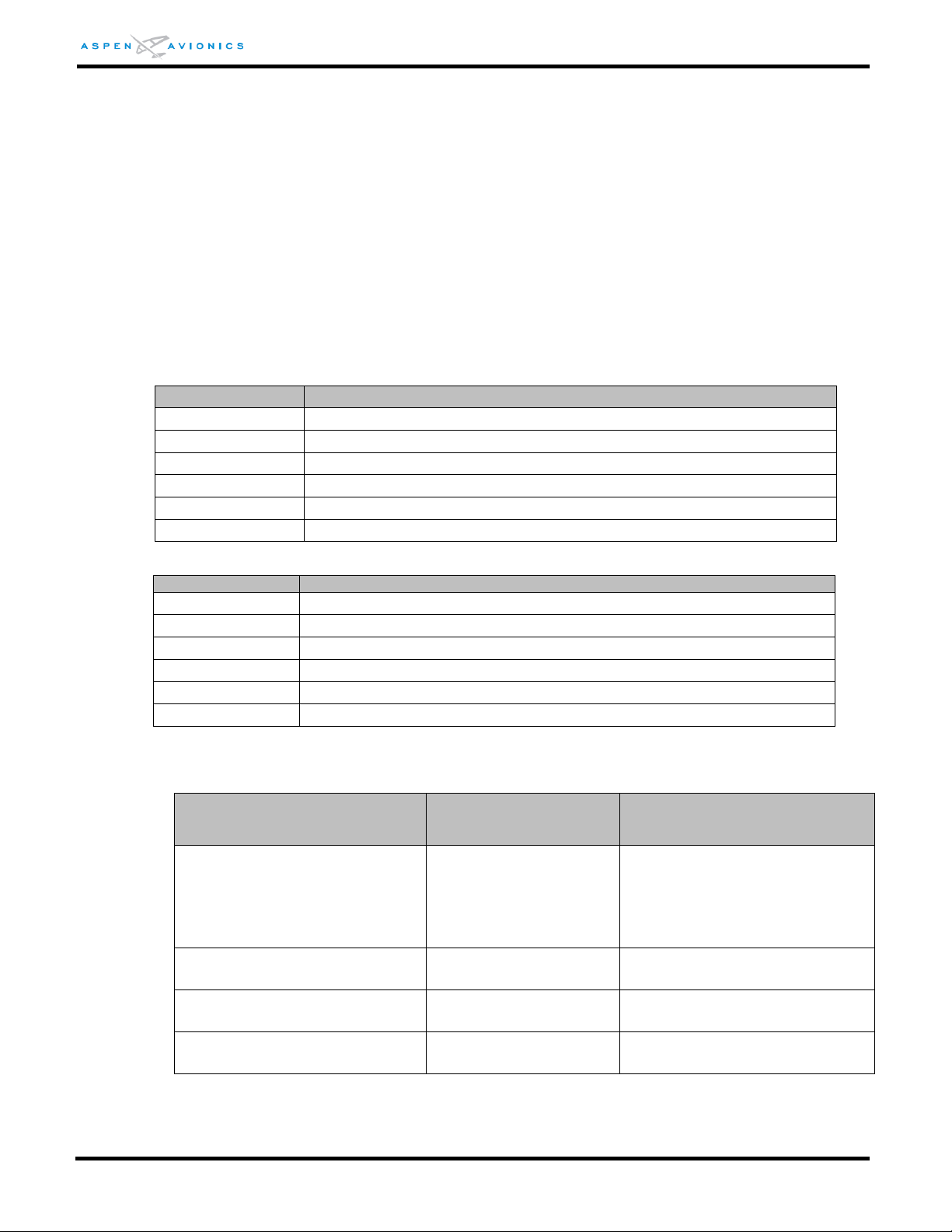
Part Number
Description
910-00101-001
EFD1000 E5, Evolution Flight Display, PMA
910-00005-004
Configuration Module, Assy, TSO
910-00003-002
RSM Rev E or later, Remote Sensor Module, Top Mount, TSO
910-00003-003
RSM Rev E or later, Remote Sensor Module, Bottom Mount, TSO
903-00001-( )
EFD1000 EFD Install Kit, TSO
903-00002-( )
RSM Install Kit, TSO
Part Number
Description
910-00004-001
ACU, Analog Converter Unit, TSO
903-00003-001
ACU Install Kit, TSO
910-00004-101
ACU2 Analog Converter Unit–HDG Synchro, TSO
903-00003-002
ACU2 Install Kit, TSO
910-00013-001
EA100 Adapter, TSO
903-00011-( )
EA100 Installation Kit, TSO
Description
Hardware Component
Software P/N and Revision
EFD1000 E5 Display
MAP (Main Application Processor)
IOP (Input/Output Processor)
910-00101-001
302-00032-001 MAP Version E5 2.10
302-00033-001 IOP Version E5 2.2
Analog Control Unit (ACU)
910-00004-001
Version 1.1
Analog Control Unit2 (ACU2)
910-00004-10x
Version 2.0
EA100
910-00013-001
Version 1.2
1 Introduction
This Installation Manual contains FAA Approved Data, but only when used to install the Aspen
Avionics EFD1000 E5 Dual Electronic Flight Instrument (EFI) system in accordance with AML-STC
SA10822SC. This document contains detailed instructions for installing the EFD1000 E5 System into
specific aircraft as listed in the AML-STC. There are regulations that must be complied with to
ensure an airworthy installation. Section 4 -STC Specific Requirements and Limitations and Section 5
-Pre-Modification Planning will guide you through these requirements.
1.1 Part Numbers
List of the major hardware components (by part number) that make up the EFD1000 E5
system.
Table 1-1: Part Numbers
Table 1-1A: EFD1000 E5 Optional LRUs
1.1.1 Latest Approved Software Versions
Table 1-2: Latest Approved Software Version
DOCUMENT # 900-00041-001 PAGE 17-226 REVISION D
© Copyright 2019 Aspen Avionics Inc.
Page 18
EFD1000 E5 Dual Electronic Flight Instrument (EFI) Install Manual
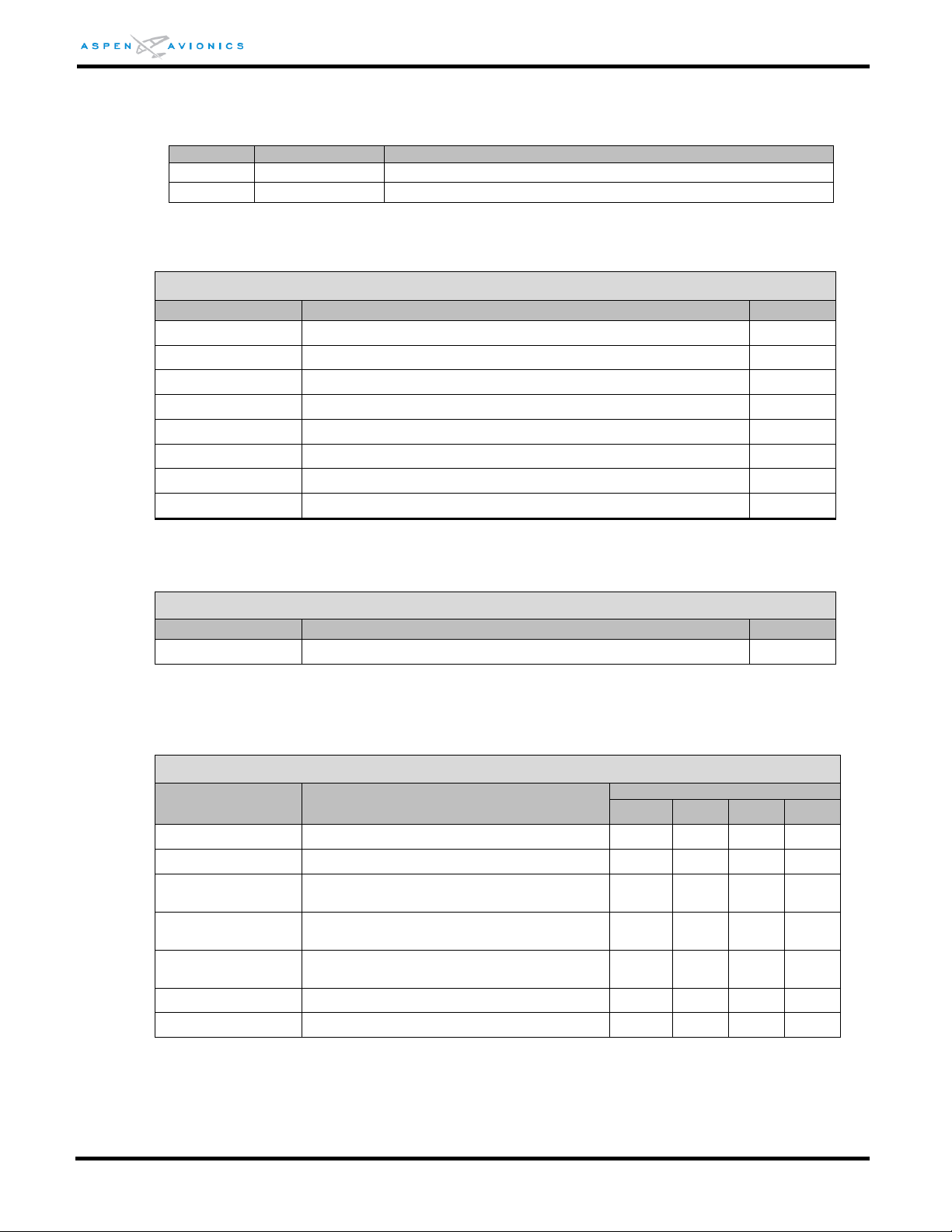
Document
P/N
Description
ICA
900-00012-001
Instructions for Continued Airworthiness
AFMS
900-00038-001
Airplane Flight Manual Supplement
Installation Kit, EFD1000 - Basic P/N 903-00001-004
Part Number
Description
Quantity
403-00002-001
Panel Mounting Bracket Assembly
1
116-00022-002
44 Pin HD D-Sub Connector with Contacts
1
116-00026-006
EMI Metal Backshell
1
275-00001-002
Pitot Quick Connector
1
275-00001-001
Static Quick Connector
1
273-00003-001
Tee Fittings for Pitot/Static, 0.25” x 0.17” x 0.25”
2
271-00001-001
Miniature Hose Clamps
8
412-00004-001
Configuration Module Cable Assembly
1
Optional EFD Recess Mount Kit P/N 903-00007-001
Part Number
Description
Quantity
903-00007-001
EFD Recess Mount Installation Kit (1 required per EFD)
1
Installation Kit, RSM P/N 903-00002-( )
Part Number
Description
Quantity by Kit Variant
-001
-002
-003
-004
412-00005-001
RSM 35ft cable assembly w/connector
1 1 -
-
412-00006-001
RSM 50ft cable assembly w/connector
- - 1
1
201-00004-001
Screw, Machined, Pan, Phillips, Brass,
8-32 11/4”, MS35214-47
4 4 4
4
212-00001-001
Nut, Hex, Locking, Nylon Insert, Brass,
8-32, MS21044B08
4 4 4
4
231-00001-001
Washer, Flat, #8, Brass, 11/64” ID,
3/8” OD, NAS1149B0832H
4 4 4
4
256-00001-001
O-Ring, AS568A-120
1 1 1
1
403-00004-001
RSM Doubler Installation Assy
- 1 -
1
1.1.2 AML-STC Document List
The following list of documents contain engineering aspects that are a part of AML-STC
SA10822SC data.
Table 1-3: AML-STC Additional Document List
1.2 Installation Kit Contents
Table 1-4: 903-00001-( ) EFD1000 EFD Install Kit
Table 1-5: 903-00007-001 EFD Recess Mount Kit (optional)
Table 1-6: 903-00002-( ) RSM Install Kits
DOCUMENT # 900-00041-001 PAGE 18-226 REVISION D
© Copyright 2019 Aspen Avionics Inc.
Page 19
EFD1000 E5 Dual Electronic Flight Instrument (EFI) Install Manual
Installation Kit, ACU P/N 903-00003-001
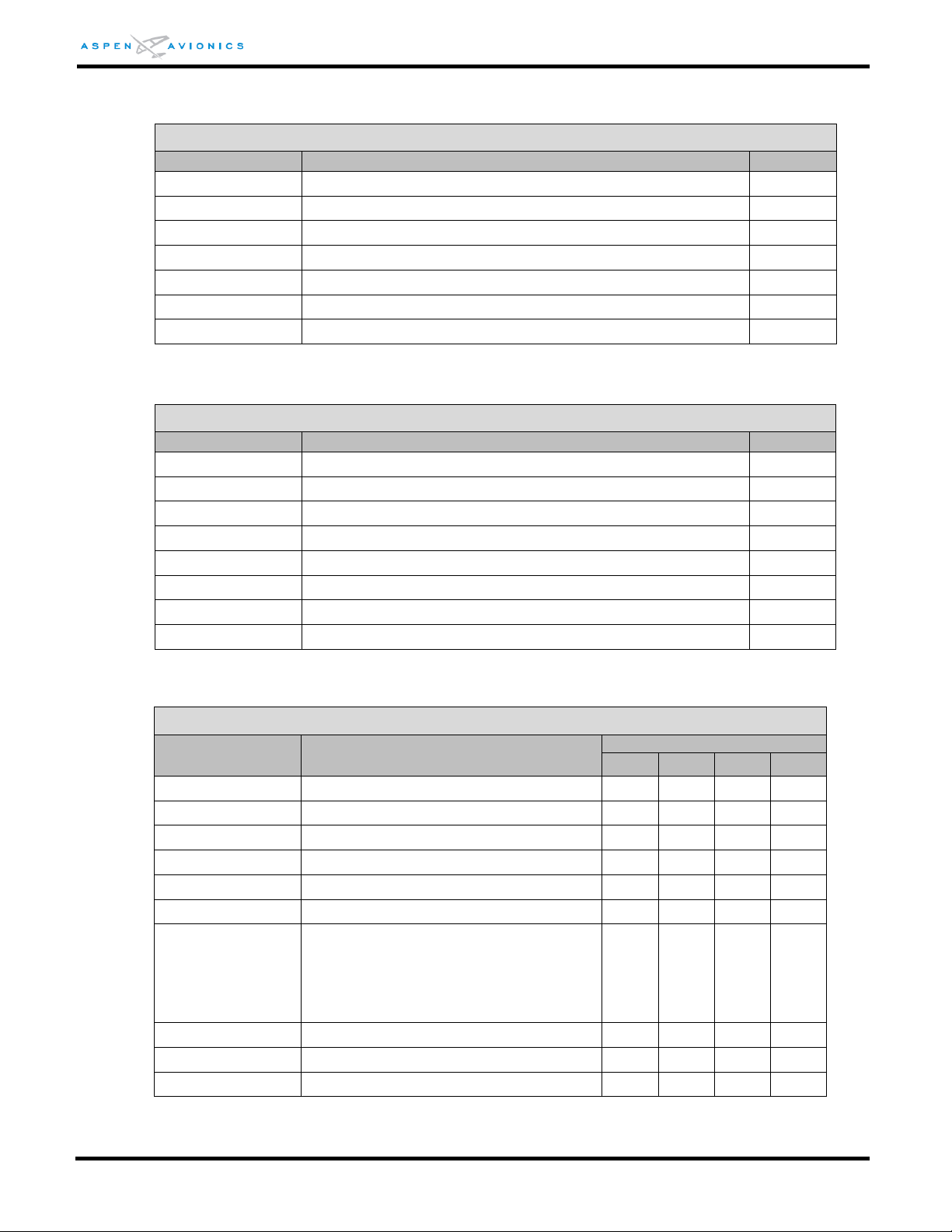
Part Number
Description
Quantity
116-00014-001
15 pin D-Sub connector
1
116-00014-002
25 pin D-Sub connector
1
116-00014-003
37 pin D-Sub connector
1
116-00026-002
DB15 EMI Back shell
1
116-00026-003
DB25 EMI Back shell
1
116-00026-005
DB37 EMI Back shell
1
116-00015-001
Crimp Sockets
77
Installation Kit, ACU2 P/N 903-00003-002
Part Number
Description
Quantity
116-00014-001
15 pin D-Sub connector
1
116-00014-002
25 pin D-Sub connector
1
116-00014-003
37 pin D-Sub connector
1
116-00052-001
62 pin high density D-Sub connector, contacts, back shell
1
116-00026-002
DB15 EMI Back shell
1
116-00026-003
DB25 EMI Back shell
1
116-00026-005
DB37 EMI Back shell
1
116-00015-001
Crimp Sockets
77
Installation Kit, EA100 P/N 903-00011-( )
Part Number
Description
Quantity by Kit Variant
-001
-002
-003
-004
116-00022-002
44 Pin HD D-Sub connector with contacts
1 1 1 1 116-00026-001
DB 25 EMI Metal Back shell
1 1 1 1 116-00014-001
15 pin D-sub connector
1 1 1
1
116-00026-007
DB15 EMI Back shell
1 1 1
1
116-00015-001
Crimp Sockets
15
15
15
15
122-00031-001
Diode Junction Splice, 200v
2 2 2
2
403-00009-001
Century II/III/IV supplemental parts
bag:
2ea. 126-00004-006 Cap 0.12uF. 400V
2ea. 132-00007-002 Resistor 1.21KΩ, 1/4W, 1%
2ea. 132-00007-004 Resistor 2.2KΩ, 1/4W, 1%
1 1 1
1
412-00013-001
EA100 10ft Ethernet Cable
- 1 - - 412-00013-002
EA100 20ft Ethernet Cable
- - 1 - 412-00013-003
EA100 30ft Ethernet Cable
- - -
1
1.3 Optional LRU Install Kits
Table 1-7: 903-00003-001 ACU Install Kit
Table 1-8: 903-00003-002 ACU2 Install Kit
Table 1-9: 903-00011-( ) EA100 Install Kits
DOCUMENT # 900-00041-001 PAGE 19-226 REVISION D
© Copyright 2019 Aspen Avionics Inc.
Page 20

EFD1000 E5 Dual Electronic Flight Instrument (EFI) Install Manual
Description
Manufacturer’s P/N or Specification
Circuit Breaker pull to open (EFD) 7.5 amp
MS 26574-7.5
Circuit Breaker (ACU) 2 amp
MS26574-2
EFD to GPS/ACU double shielded cable
M27500-22TG2V64
Unshielded wire 24, 22, 20 AWG
MIL-W-22759/16
Shielded Wire 22/20 AWG
MIL-C-27500
3/16” pitot/static tube (EFD to T fitting
MIL-DTL-5593
EFD Mounting Screws #6-32, 6 ea.
MS24693-S30
EFD Mounting Lock Nuts #6-32
MS21044N06
EFD Mounting Washers
NAS1149FN632P
ACU Mounting Screw #8-32
MS35206-XXX
ACU Mounting Lock Nuts #8-32
MS21044N08
ACU Mounting Washers
NAS1149FN832P
Description
Manufacturer P/N or Specification
E5 Master switch –rated for 7.5 amps cont.
MS35058-22 SPST switch
Circuit Breaker/Switch 7.5amp
(optional – in lieu of separate C/B and switch)
MS24509-A- 7½
*Tinned Copper Over Braid
*used in lieu of double shielded wire
MIL-SPEC# AA59569R36T0250 ¼”
MIL-SPEC# AA59569R36T0500 ½”
RSM Doubler
Installer fabricated per Section 6.9.5
RSM Shim
(may be required on extreme mounting angles)
Installer fabricated per Section 6.9.9
RSM sealant non-pressure vessel mounting
MIL-A-46146, Dow 738
7 conductor shielded cable
For installer fabricated harness using
116-00020-001 connector.
M27500-A24SD7T23/
M27500-22TG7T14
Description
Manufacturer P/N or Specification
A/P AHRS FAIL press-to-test indicator
“dimmable cat’s-eye”
Electroswitch Electronic Products
MS25041-4 (dimmable)
(also available from Aircraft Spruce)
EA100 Ethernet Cable
(Cat 5e Ethernet cable (MX100P-24)
Order Aspen Avionics EA100
Installation kits 903-00011-002,
-003, or -004 which include the cable.
EA100 Mounting Lock Nuts #8-32 (6)
MS21044N08
EA100 Mounting Washers (6)
NAS1149FN832P
EA100 Mounting Screw #8-32 (6)
MS35206-XXX
Circuit Breaker 2A
MS26574-2
1.4 Accessories Required but Not Supplied – EFD1000 E5
Table 1-10: EFD1000 E5 Accessories Required but Not Supplied
1.5 Optional Accessories Not Supplied – EFD1000 E5
1.6 Optional Accessories Required but Not Supplied – EA100
Table 1-12: EA100 Optional Accessories Required but Not Supplied
DOCUMENT # 900-00041-001 PAGE 20-226 REVISION D
Table 1-11: E5 Optional Accessories Not Supplied
© Copyright 2019 Aspen Avionics Inc.
Page 21

EFD1000 E5 Dual Electronic Flight Instrument (EFI) Install Manual
Tool
Manufacturer Part Number
Usage
Positronics crimp tool
9507-0-0-0
All D-Sub
Daniels crimp tool
AFM8
All D-Sub
Positioner
M81969/1-02, K13-1
ACU/ACU2 –J1/J2/J3, EA100 J1,
CG100 J2
Positioner
M81969/1-01, K41
EFD, ACU2 – J4, EA100 J2, CG100 J1
Magnetometer
HMR2300‐DEMO‐D21‐232
RSM Installation
Aspen Avionics Inc
5001 Indian School Road NE
Albuquerque, NM 87110
(505) 856-5034
EDMO Distributors, Inc. (Wire, Cable)
12830E Mirabeau Pkwy
Spokane Valley, WA 99216
(800) 235-3300
A.E. Petsche Co. (Double Shielded & RSM Cable)
2112 West Division St.
Arlington, TX 76012-3693
(817) 461-9473
Wirenetics (Thermax Cat 5e cable)
27737 Avenue Hopkins
Valencia, CA 91355
(661) 257-2400
Positronic Industries Inc. (Crimpers/Connectors)
423 N. Campbell Ave.
Springfield, MO 65801
(417) 866-2322
Aircraft Spruce
225 Airport Circle
Corona, CA 92889
877-477-7823
www.aircraftspruce.com
1.7 Special Tools Required
Table 1-13: Special Tools
1.8 Vendor Information
1.9 Warranty Registration
Registration of LRU part numbers and serial numbers must be recorded. Activating the
warranty on the EFD1000 E5 system is just one important aspect of providing a satisfying
installation experience for our customers
1.10 Regulatory Compliance
1.10.1 Technical Standard Order
The RSM, CM, ACU, and EA100 components of the EFD1000 E5 system are produced
under Technical Standard Order Authorization (TSOA).
1.10.2 PMA Approval
The EFD (Electronic Flight Display) component of the EFD1000 E5 system is approved
under Parts Manufacturer Approval (PMA).
DOCUMENT # 900-00041-001 PAGE 21-226 REVISION D
© Copyright 2019 Aspen Avionics Inc.
Page 22

EFD1000 E5 Dual Electronic Flight Instrument (EFI) Install Manual
1.10.3 Software Certification
The EFD1000 E5 system software is approved using system level verification to approve
software and show compliance to 23.1309 (and 23.1301) in lieu of RTCA/DO-178/C, in
accordance with a Project-Specific Policy Statement dated June 13, 2018.
1.10.4 Environmental Compliance
All system components meet the environmental test requirements defined in RTCA/DO160E as shown in the environmental qualification forms in Section 13.
1.10.5 Installation Approval
Installation of the EFD1000 E5 is FAA approved under AML STC SA10822SC. This
installation manual contains FAA Approved Data, but only when used to install the Aspen
Avionics EFD1000 E5 display system in accordance with this AML STC. The data in this
manual may be used only by those authorized to install the EFD1000 E5 in writing, and
then only to support installation of the EFD1000 E5, either under STC SA10822SC, or
(when FAA-authorized) as a follow-on field approval for aircraft not included in the
Approved Model List. Use of this data for any other purpose requires separate written
approval from Aspen Avionics Inc.
1.11 Field Replaceable Parts
Refer to Appendix D of this manual and the ICA for a list of field replaceable parts.
1.12 Reserved
DOCUMENT # 900-00041-001 PAGE 22-226 REVISION D
© Copyright 2019 Aspen Avionics Inc.
Page 23

EFD1000 E5 Dual Electronic Flight Instrument (EFI) Install Manual
2 Equipment Specifications and Limitations
2.1 EFD1000 E5
2.1.1 General Specifications
Part Number ...................... 910-00101-001
Width/Height ..................... 3.50 in./7.00 in. (Measured at Bezel)
Can Depth ......................... 4.15 in. (Rear of Bezel to Rear of Can)
Overall Depth .................... 6.35 in. (Knob to Rear Pressure Fitting)
Weight ............................... 2.9 lbs. with bracket
Display Type ...................... 6.0 in. Diagonal LCD (400x760)
Face .................................. Anti-Reflective Coated Glass
Backlight ........................... High Intensity White LED
Rotary Knobs ..................... Optical Encoder with Momentary Push
Dimming ........................... Manual & Automatic (Front Bezel Mounted Sensor)
2.1.2 Operational Specifications
Operating Temp ................ -20°C to +70°C
Storage Temp .................... -55°C to +85°C
Max Operating Altitude ..... 35,000 ft. Unpressurized/ 55,000 ft. Pressurized
Cooling ............................. Integral Fan
Max Humidity .................... 95% at 50°C
Input Voltage ..................... +9 to +32 VDC (Note: Input power must transition >11VDC
to turn on the unit
Nominal Current ................ 2.4/4.8 Amps (28v/14v)
2.1.3 I/O Specifications
ARINC 429 Inputs .............. 2 Low/High Speed
ARINC 429 Outputs ........... 1 Low/High Speed
RS-232 Inputs ................... 2
RS-232 Outputs ................ 3
Pitot/Static ........................ Quick Connect
2.1.4 Certification Specifications
FAA-PMA
DOCUMENT # 900-00041-001 PAGE 23-226 REVISION D
© Copyright 2019 Aspen Avionics Inc.
Page 24
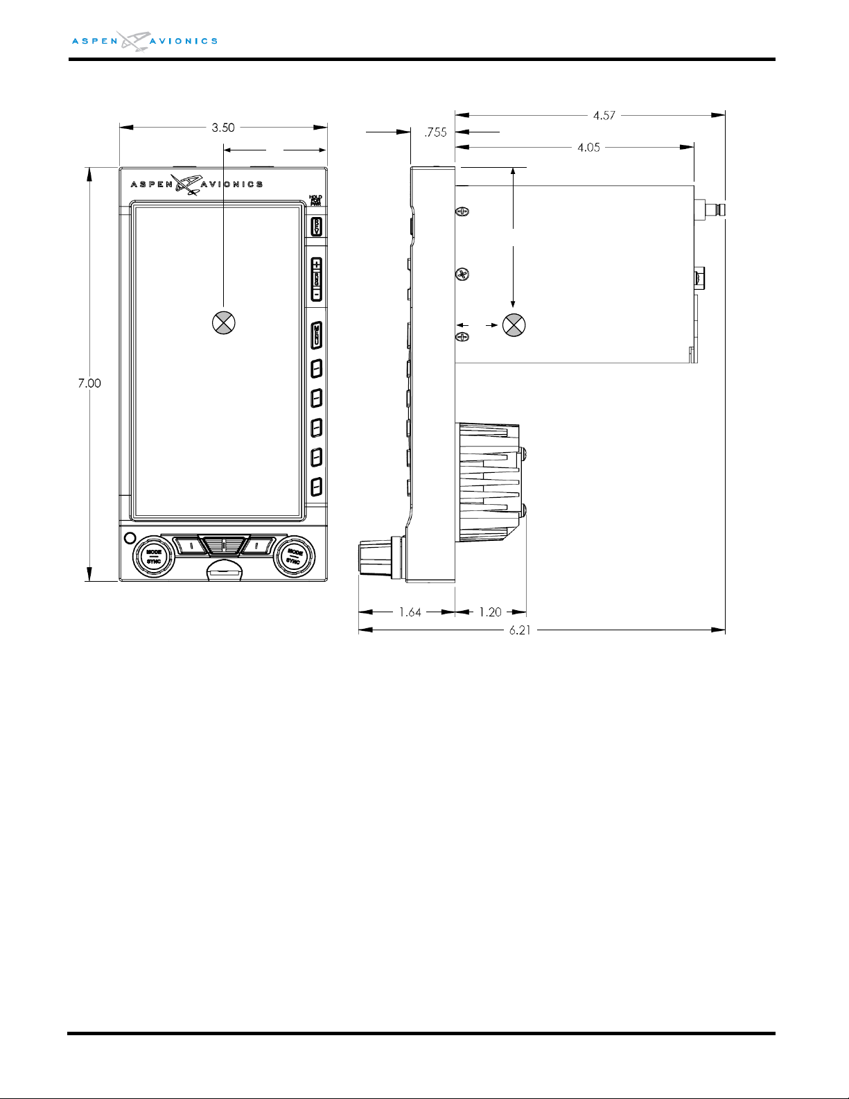
EFD1000 E5 Dual Electronic Flight Instrument (EFI) Install Manual
1.75
1.50
2.75
C.G.
EVOLUTION
2.1.5 EFD1000 E5 Outline Drawing
Figure 2-1: EFD1000 E5 Outline Drawing (inches)
2.1.6 Design Eye Viewing Envelope
The following information defines the viewing envelope within which the EFD1000 E5
complies with the equipment standards.
Minimum and maximum distance from the center of the EFD display surface:
10 inches (25.4 cm) minimum to 45 inches (114.3 cm) maximum.
Total viewing angles:
From -30º to +30º (left/right), and +30º to -30º (top/bottom) perpendicular to the EFD
front glass surface.
DOCUMENT # 900-00041-001 PAGE 24-226 REVISION D
© Copyright 2019 Aspen Avionics Inc.
Page 25

EFD1000 E5 Dual Electronic Flight Instrument (EFI) Install Manual
2.2 Remote Sensor Module (RSM)
2.2.1 General Specifications
Part Number ...................... 910-00003-002, (RSM, top mount), Rev E or later
910-00003-003, (RSM, bottom mount), Rev E or later
......................................... 910-00003-001, (RSM, top mount, Pro upgrade option), Rev
G or later
Width ................................ 2.65 in. (Measured at Base)
Height ............................... 1.1 in. maximum (Measured from Base)
Length ............................... 4.40 in. (Front to Rear)
Weight ............................... 0.5 lbs.
2.2.2 Operational Specifications
Operating Temp ................ -55°C to +70°C
Storage Temp .................... -55°C to +85°C
Max Operating Altitude ..... 55,000 ft. Unpressurized
Cooling ............................. None Required
Max Humidity .................... 95% at 50°C
Input Voltage ..................... Provided by EFD
Nominal Current ................ Included in EFD Current
2.2.3 I/O Specifications
Magnetometer ................... Proprietary Digital
2.2.4 Certification Specifications
The RSM is certified as a component of the EFD1000 E5 system
Software:
NONE
Complex Electronic Hardware (CEH):
NONE
Environmental:
RTCA DO-160E ................. See Environmental Qualification Form Section 13
DOCUMENT # 900-00041-001 PAGE 25-226 REVISION D
© Copyright 2019 Aspen Avionics Inc.
Page 26
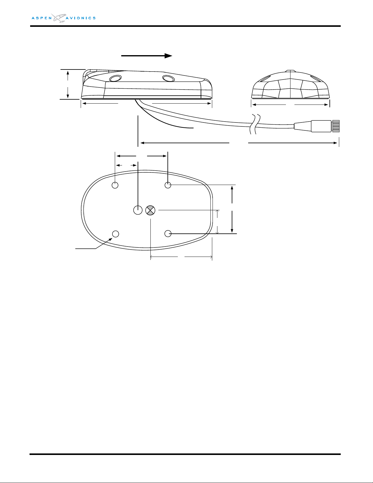
EFD1000 E5 Dual Electronic Flight Instrument (EFI) Install Manual
24 inches
4.36
1.1 max
2.64
1.750
1.625
4 X 0.194
CABLE
FEEDTHRU
0.75
FWD
C.G.
2.10
0.813
2.2.5 Outline Drawing:
Figure 2-2: RSM Outline Drawing (inches)
2.3 Configuration Module (CM)
There is a single hardware part number Configuration Module, which is then loaded with the
appropriate configuration settings image file that establishes the functionality and feature set
of the attached EFD1000 E5 system.
2.3.1 General Specifications
Part Number ...................... 910-00005-004
Width ................................ 1.0 in.
Height ............................... 0.55 in.
Length ............................... 1.85 in.
Weight ............................... 0.1 lbs.
DOCUMENT # 900-00041-001 PAGE 26-226 REVISION D
© Copyright 2019 Aspen Avionics Inc.
Page 27
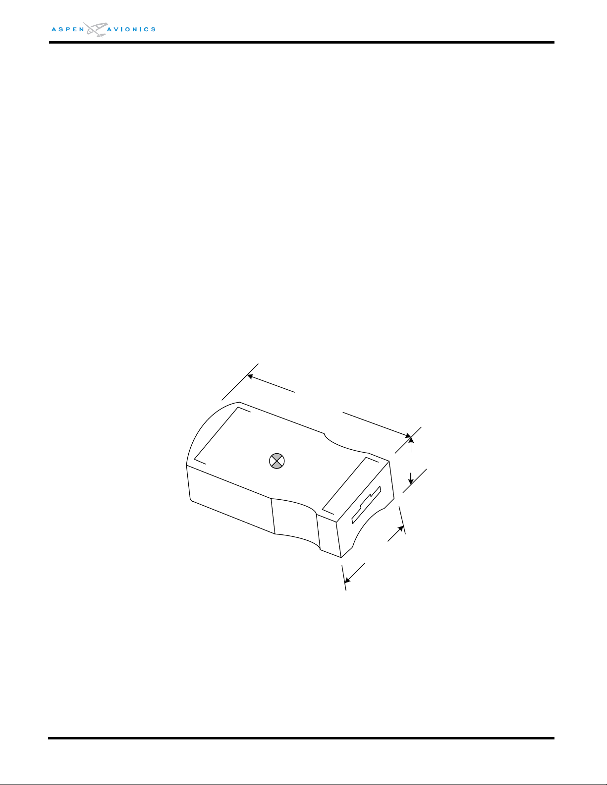
EFD1000 E5 Dual Electronic Flight Instrument (EFI) Install Manual
1
.
85
in
1
.
0
in
0.55 in
C.G.
C.G. is in the dimensional center of
the module for HxWxL
2.3.2 Operational Specifications
Operating Temp ................ -20°C to +70°C
Storage Temp .................... -55°C to +85°C
Max Operating Altitude ..... 35,000 ft. Unpressurized/ 55,000 ft. Pressurized
Cooling ............................. None Required
Max Humidity .................... 95% at 50°C
Input Voltage ..................... Provided by EFD
Nominal Current ................ Included in EFD Current
2.3.3 I/O Specifications
Proprietary Digital
2.3.4 Certification Specifications
The Configuration Module is certified as a component of the EFD1000 E5 system
Software:
NONE
Complex Electronic Hardware (CEH):
Environmental:
RTCA DO-160E ................. See Environmental Qualification Form Section 13
2.3.5 Outline Drawing
NONE
Figure 2-3: Configuration Module Outline Drawing (inches)
DOCUMENT # 900-00041-001 PAGE 27-226 REVISION D
© Copyright 2019 Aspen Avionics Inc.
Page 28

EFD1000 E5 Dual Electronic Flight Instrument (EFI) Install Manual
2.4 Analog Converter Unit (ACU)
2.4.1 General Specifications
Part Number ...................... 910-00004-001
Width ................................ 5.75 in. including mounting flanges
Height ............................... 1.60 in.
Length ............................... 4.28 in.
Weight ............................... 0.8 lbs.
2.4.2 Operational Specifications
Operating Temp ................ -40°C to +55°C
Storage Temp .................... -55°C to +85°C
Max Operating Altitude ..... 35,000 ft.
Cooling ............................. None Required
Max Humidity .................... 95% at 50°C
Input Voltage ..................... +11 to +32 VDC
Nominal Current ................ 0.5/1.0 Amps (28v/14v)
2.4.3 I/O Specifications
ARINC 429 Inputs .............. 2 Low Speed
ARINC 429 Outputs ........... 2 Low Speed
RS-232 Inputs ................... 1 (software loading only)
VHF Nav Receiver ............... 1 Analog input
GPS Receiver ...................... 1 Analog input
GPS OBS Interface .............. 1 Output
Autopilot Interface ............. 1 Analog port
2.4.4 Certification Specifications
The ACU is certified as a component of the EFD1000 E5 system
Software:
RTCA DO-178B ................. Level C
Complex Electronic Hardware (CEH):
Environmental:
RTCA DO-160E ................. See Environmental Qualification Form Section 13
NONE
DOCUMENT # 900-00041-001 PAGE 28-226 REVISION D
© Copyright 2019 Aspen Avionics Inc.
Page 29
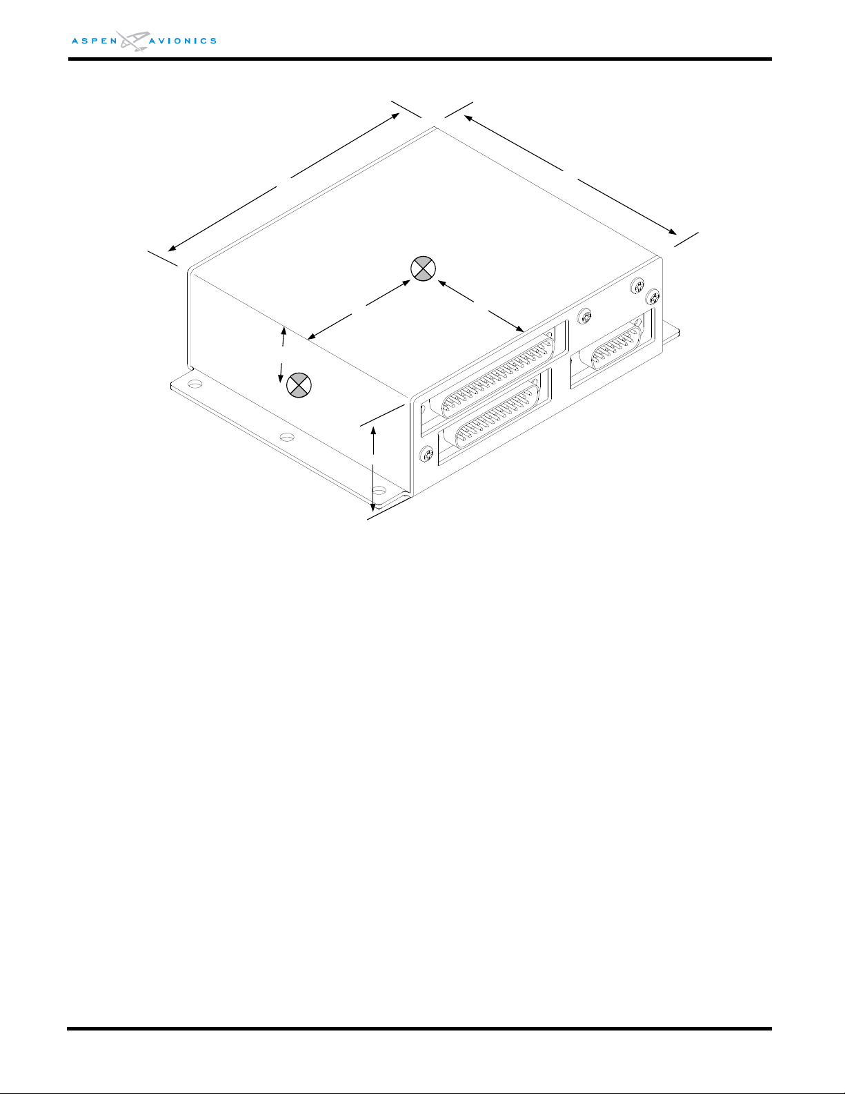
EFD1000 E5 Dual Electronic Flight Instrument (EFI) Install Manual
4
.
72
4
.
28
1.60
2
.
14
2
.
36
0
.
80
C.G.
2.4.5 Outline Drawing:
Figure 2-4: ACU Outline Drawing (inches)
2.5 Analog Converter Unit 2
2.5.1 General Specifications
Part Number ...................... 910-00004-101, -102
Width ................................ 5.75 in. including mounting flanges
Height ............................... 2.25 in.
Length ............................... 4.28 in.
Weight ............................... 1.1 lbs.
2.5.2 Operational Specifications
Operating Temp ................ -40°C to +55°C
Storage Temp .................... -55°C to +85°C
Max Operating Altitude ..... 35,000 ft.
Cooling ............................. None Required
Max Humidity .................... 95% at 50°C
Input Voltage ..................... +11 to +32 VDC
Nominal Current ................ 0.5/1.0 Amps (28v/14v)
2.5.3 I/O Specifications
ARINC 429 Inputs .............. 2 Low/High Speed
ARINC 429 Outputs ........... 3 Low/High Speed
DOCUMENT # 900-00041-001 PAGE 29-226 REVISION D
© Copyright 2019 Aspen Avionics Inc.
Page 30
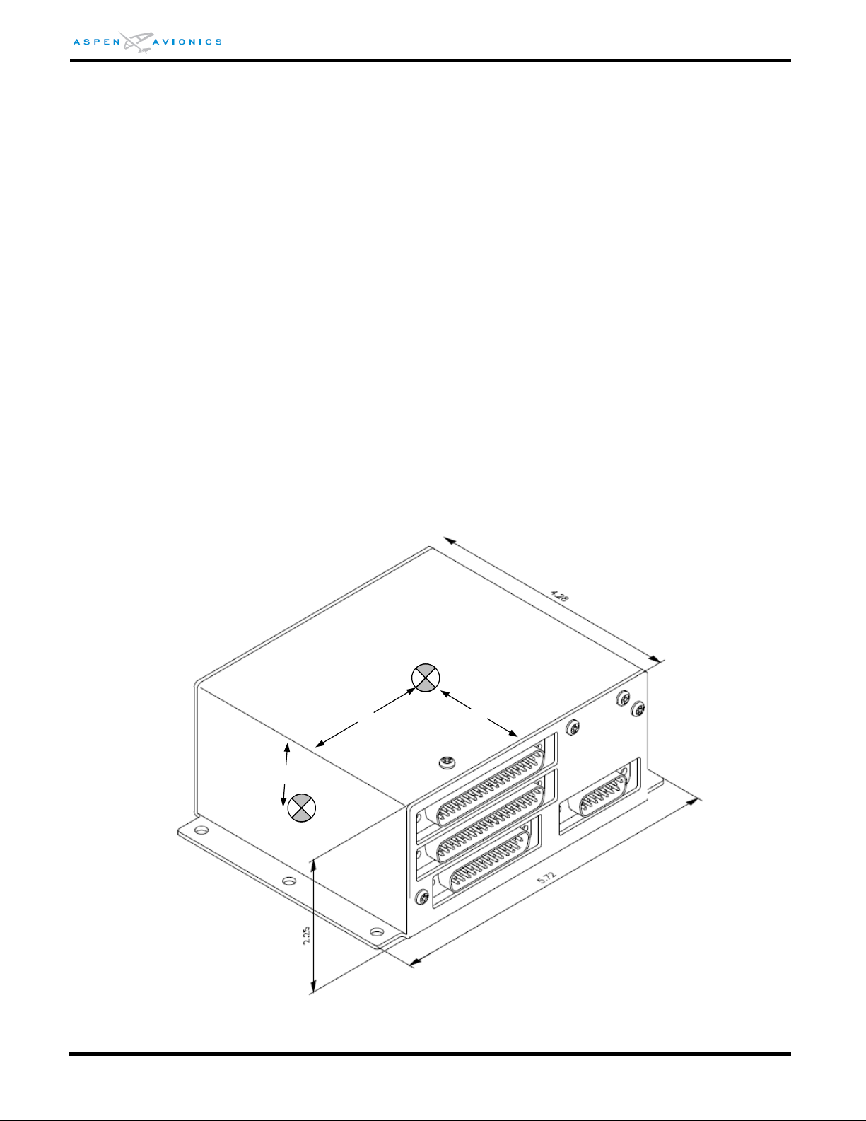
EFD1000 E5 Dual Electronic Flight Instrument (EFI) Install Manual
2
.
36
2
.
14
1
.
12
RS-422 .............................. 2 Transmitters
RS-422 .............................. 2 Receivers
RS-232 Input ..................... 1 (software loading only)
VHF Nav Receiver ............... 1 Analog input
GPS Receiver ...................... 1 Analog input
GPS OBS Interface .............. 1 Output
Autopilot Interface ............. 1 Analog port
G/S and NAV Flag to A/P ... low level (-101), Discrete to drive Superflag (-102)
Heading Synchro ............... 1 Output with 26Vac Reference
2.5.4 Certification Specifications
The ACU2 is certified as a component of the EFD1000 E5 system
Software:
RTCA DO-178B ................. Level C
Complex Electronic Hardware (CEH):
Environmental:
RTCA DO-160E ................. See Environmental Qualification Form Section 13
2.5.5 Outline Drawing
NONE
Figure 2-5: ACU2 Outline Drawing (inches)
DOCUMENT # 900-00041-001 PAGE 30-226 REVISION D
© Copyright 2019 Aspen Avionics Inc.
Page 31

EFD1000 E5 Dual Electronic Flight Instrument (EFI) Install Manual
3 System Description
3.1 EFD1000 E5 Dual Electronic Flight Instrument (EFI) system
The EFD1000 E5 contains an internal ADAHRS that is used to provide attitude, heading and air
data for the display. The EFD1000 E5 comes standard with an internal battery to provide 30minute operation in the event of power loss
Additional equipment is normally installed in support of the displays, including the Remote
Sensor Module (RSM), Configuration Module (CM), EA100 and optional Analog Converter Unit
(ACU). An external GPS receiver is required for IFR but is optional for airplanes restricted to
VFR. Optionally a remote VOR navigation receiver may be connected.
The EFD1000 E5 provides display of attitude, airspeed, altitude, direction of flight, vertical
speed, turn rate, and turn quality. The system can provide display of navigation information,
pilot-selectable indices (“bugs”), and annunciations to increase situational awareness and
enhance flight safety.
3.2 EFD1000 E5 Flight Display (EFD)
The EFD1000 E5 (EFD) display is a digital system that consists of a high-resolution 6” diagonal
color LCD display, user controls, photocell and Micro SD data card slot. The rear portion of
the EFD includes a non-removable electronics module that contains a full air data computer,
attitude heading reference system, power supplies, internal battery, and dual processor
electronics. Also on the rear of the unit, a fan is provided to cool the backlight and
electronics.
The EFD mounts to the front surface of most instrument panels. The electronics module and
cooling fins on the back are sized to fit into existing instrument panel holes. A recess-mount
bracket is available to mount the displays nearly flush with the instrument panel.
The mechanical design allows the instrument to be installed in a vertically oriented pair of
instrument openings, without interfering with the surrounding instruments. The installation
requires minimal mechanical modifications to most general aviation aircraft instrument
panels. The EFD contains a microSD card port and reader at the bottom of the display bezel.
When authorized, software updates and system upgrades can be installed using the card port.
This is a maintenance action that is accomplished by authorized maintenance personnel.
The EFD is a digital system and supports both ARINC 429 and RS-232 digital interfaces. In
installations with a modern digital radio installation, the display connects directly to the
interfaced equipment.
In installations that require interfaces to analog avionics (i.e., older VLOC navigation radios
and autopilots) an optional ACU is required to digitize the analog signals into ARINC 429.
DOCUMENT # 900-00041-001 PAGE 31-226 REVISION D
© Copyright 2019 Aspen Avionics Inc.
Page 32

EFD1000 E5 Dual Electronic Flight Instrument (EFI) Install Manual
3.3 Remote Sensor Module (RSM)
The RSM is required and connects directly to the EFD display. It physically resembles a
traditional GPS antenna and follows the industry standard mounting hole pattern.
The RSM contains all of the sensors that must be remotely located from the EFD display unit.
The RSM is powered by the EFD through a shielded wire harness and contains the Magnetic
“flux” sensors.
All RSM versions must be mounted in a magnetically quiet environment. The -002 RSM may be
mounted internally within the fuselage or wing structure or externally on the fuselage. The 003 bottom mount RSM can be mounted internally in the upside down orientation or
externally on the underside of the aircraft. The -001 RSM is eligible for installation.
CAUTION: Do not mount an RSM made for inverted operation on the top of the aircraft as reverse
magnetic sensing will result, producing unacceptable AHRS performance.
3.4 Configuration Module (CM)
The Configuration Module retains system configuration settings and calibration data. The
Configuration Module connects to the EFD through a short, fabricated, harness and is fastened
to the main wiring bundle of the display.
Each display has an associated Configuration Module that retains that display’s aircraft
specific configuration, calibration data and user settings. This scheme permits the display
hardware to be replaced without re-entering the installation settings or re-calibrating the EFD.
3.5 Analog Converter Unit (ACU)
The optional Analog Converter Unit (ACU) provides compatibility with older, analog-based
avionics when required. The ACU converts and concentrates multiple analog interfaces to
digital signals supported by the EFD. Control parameters, such as desired heading and
selected course, are also sent from the EFD to the ACU for conversion to analog format for
autopilot support.
The ACU is required when any of the following capabilities are required:
Interface to supported autopilots
Interface to supported non-ARINC 429 VLOC navigation radios
Interface to supported non-ARINC 429 GPS navigators
If digital radios (i.e., Garmin 4XX/5XX and similar series radios) are equipped in the aircraft
and no other aircraft interfaces are to be used, then the ACU is not required.
3.6 Analog Converter Unit 2 (ACU2)
The optional ACU2 provides all the features of the standard ACU above but adds the following
capabilities:
DOCUMENT # 900-00041-001 PAGE 32-226 REVISION D
© Copyright 2019 Aspen Avionics Inc.
Page 33
EFD1000 E5 Dual Electronic Flight Instrument (EFI) Install Manual
EFD1000 E5
Flight Display
Existing Aircraft Pitot Line
Existing Aircraft Static Line
Digital GPS/VLOC
ARINC429
SPI
I2C
Analog
Converter Unit
(ACU, ACU2)
Analog NAV Source
AutoPilot
Configuration Module
Remote Sensor
Module (RSM)
RS-232
Legacy GPS
RS232
Aircraft Power
Analog GPS/VLOC via ACU
Digital GPS/VLOC
EA100
Autopilot
AHRS
Ethernet
Heading Synchro (bootstrap) output to drive ancillary equipment that requires an
ARINC 407 analog heading input.
High Speed A429 data output when required.
3.7 System Architecture
The system architecture in Figure 3-2 shows the relationships of the EFD1000 E5 with its
associated RSM, Configuration Module and optional ACU and EA100.
Figure 3-1: EFD1000 E5 System Architecture
DOCUMENT # 900-00041-001 PAGE 33-226 REVISION D
© Copyright 2019 Aspen Avionics Inc.
Page 34

EFD1000 E5 Dual Electronic Flight Instrument (EFI) Install Manual
THIS PAGE IS INTENTIONALLY LEFT BLANK
DOCUMENT # 900-00041-001 PAGE 34-226 REVISION D
© Copyright 2019 Aspen Avionics Inc.
Page 35

EFD1000 E5 Dual Electronic Flight Instrument (EFI) Install Manual
4 STC Specific Requirements and Limitations
4.1 EFD1000 E5 System Limitations
This section contains requirements that must be considered before installing the EFD1000 E5
system.
A turn and slip indicator (or backup attitude indicator) and an IFR GPS are always required for
airplanes certified for IFR operation. For airplanes restricted to VFR, see Section 4.5, Special
Consideration for Aircraft Limited to VFR.
The EFD1000 E5 is not approved for aircraft with a maximum takeoff weight (MTOW)
exceeding 6000lbs.
This installation is not authorized as a Flight Display for Category II Operations or RVSM
Operations.
4.2 EA100 Installation Limitations (EA100 is optional)
The EA100 must be installed in a temperature-controlled part of the aircraft.
The EA100 must not be installed on the firewall.
Maximum Ethernet cable length between the EFD and the EA100 is 30 feet.
An “A/P AHRS FAIL” light (amber) must be installed in the pilot primary field-of-view.
AFMS 900-00038-001 Rev ( ) or later FAA approved revision with the Configuration Matrix
in Section 1.2 completed must be inserted in the Airplane Flight Manual.
4.3 Authorized Configurations
The following are authorized configurations of the Aspen EFD1000 E5:
DOCUMENT # 900-00041-001 PAGE 35-226 REVISION D
© Copyright 2019 Aspen Avionics Inc.
Page 36
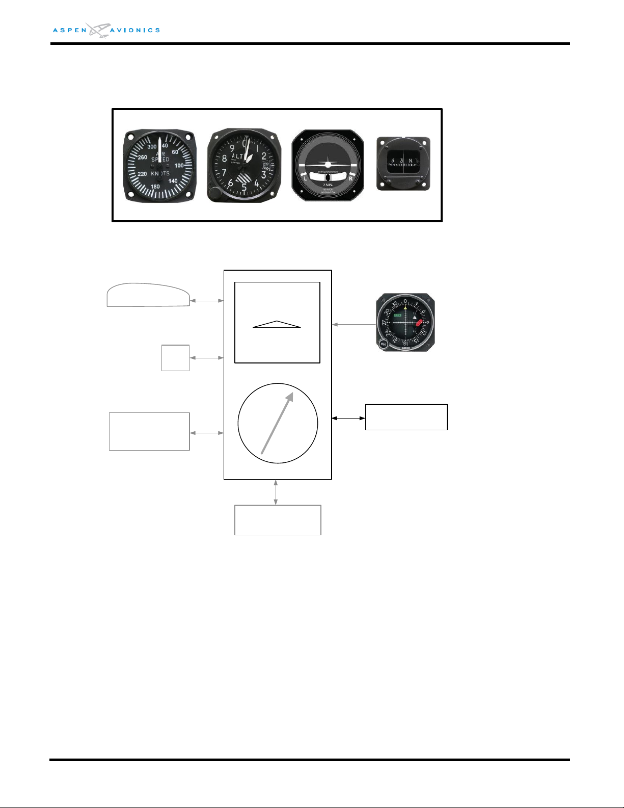
EFD1000 E5 Dual Electronic Flight Instrument (EFI) Install Manual
E5
RSM
ACU
optional
CM
EA100
optional
Required Instruments (existing)
Secondary NAV
Indicator(2)
IFR GPS
IAS(1)
ALT(1)
Compass
Requires:
-existing Altimeter(1)
-existing Airspeed indicator(1)
-existing Turn/Bank indicator(1)(3)
-Magnetic Direction Indicator (compass)
-Secondary navigation indicator(2) (when required – see section 4.4.5)
-IFR GPS navigator input (see Section 5 table 5-2 for compatible devices)
(1) – The airspeed, altimeter and turn/bank indicators of the E5 are
secondary (advisory) functions. These existing instruments must not be
removed or relocated.
(3) – The Turn/Bank indicator may be removed provided an acceptable
backup Attitude indicator is installed.
IFR Approved Configuration
Turn/Bank(1)(3)
DOCUMENT # 900-00041-001 PAGE 36-226 REVISION D
Figure 4-1: EFD1000 E5 Authorized IFR Configuration
© Copyright 2019 Aspen Avionics Inc.
Page 37
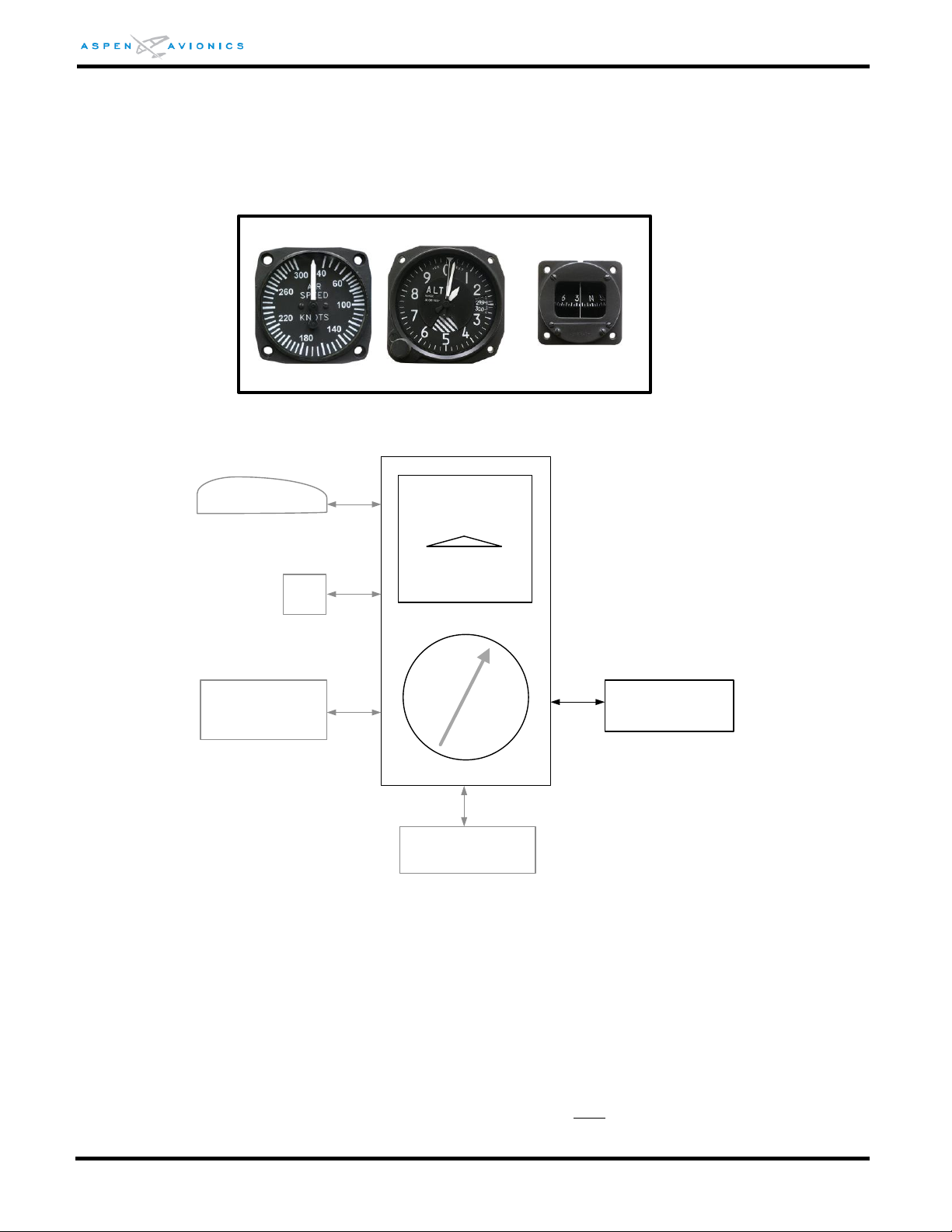
EFD1000 E5 Dual Electronic Flight Instrument (EFI) Install Manual
E5
RSM
ACU
optional
CM
Required Instruments (existing)
IAS(1)
ALT(1)
Compass(1)
Requires:
-existing Altimeter(1)
-existing Airspeed indicator(1)
-Magnetic Direction Indicator (compass)(1)
(1) –These existing instruments must not be removed or relocated.
VFR with Standby Instruments
GPS
optional
EA100
optional
DOCUMENT # 900-00041-001 PAGE 37-226 REVISION D
Figure 4-1A: EFD1000 E5 Authorized VFR with Backups Configuration
© Copyright 2019 Aspen Avionics Inc.
Page 38

EFD1000 E5 Dual Electronic Flight Instrument (EFI) Install Manual
4.4 General Standby Instrument Requirements for IFR-Capable Airplanes
The EFD1000 E5 flight display presents various indicators of attitude, altitude, airspeed,
vertical speed, rate of turn and slip skid. The existing aircraft also has these indicators. Only
the attitude indicator on the EFD1000 E5 is a primary instrument. The EFD1000 E5 displays of
airspeed, altitude, vertical speed, rate of turn and slip skid are all secondary displays and the
existing indicators remain the primary. For this reason, the existing instruments may not be
removed or relocated under this STC. The exception is that the existing turn/bank indicator
may be removed if it is replaced with a backup attitude indicator.
The existing magnetic direction indicator “whiskey compass” may not be removed during the
installation of the EFD1000 E5 system.
WA RN IN G: Failure to adhere to these specific instrument layout requirements and EFD1000 E5
configuration requirements and limitations will violate the STC.
4.4.1 Pneumatic Attitude (existing)
The existing attitude indicator may be removed unless it is required for autopilot or flight
director purposes. It may also be retained and used as the secondary source of attitude if
it is desired to remove the turn and slip indicator or turn coordinator.
Removal of pneumatic standby instruments and installation of electric standby
instruments is not authorized by this STC. Separate installation approval would be
required.
Changing the vacuum source of the AI is beyond the scope of the STC and must be
separately approved.
4.4.2 Electric Attitude (existing)
The existing attitude indicator may be removed unless it is required for autopilot or flight
director purposes. It may also be retained and used as the secondary source of attitude if
it is desired to remove the turn and slip indicator or turn coordinator.
The E5 contains an internal battery that maintains power for 30 minutes under all
foreseeable operating conditions. No battery backup required on the electric Attitude
indicator or turn and slip indicator or turn coordinator.
The installation of dual independent electrical systems or a standby (emergency) aircraft
battery is not authorized by this STC. Separate installation approval would be required.
4.4.3 Existing Attitude Positioning (if keeping)
The position of the existing Attitude Indicator will depend on whether the turn and slip
indicator is being retained or removed.
DOCUMENT # 900-00041-001 PAGE 38-226 REVISION D
© Copyright 2019 Aspen Avionics Inc.
Page 39
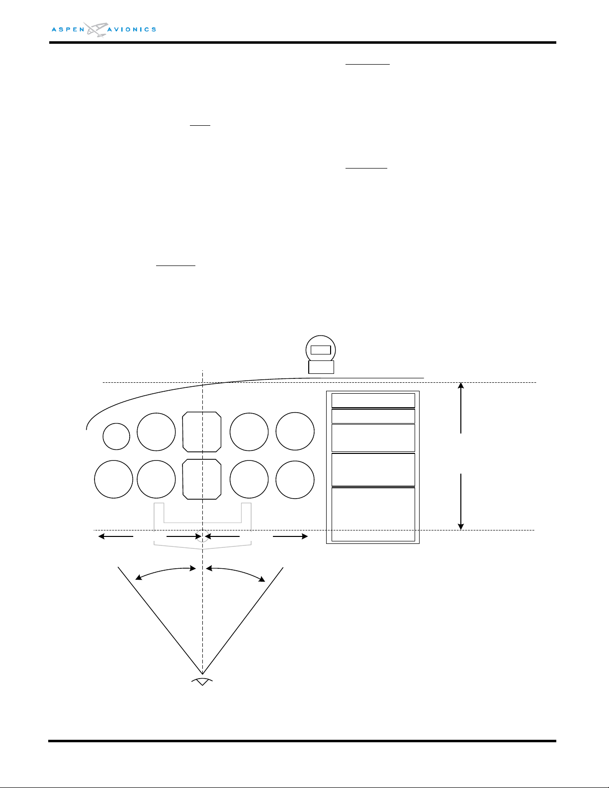
EFD1000 E5 Dual Electronic Flight Instrument (EFI) Install Manual
35º
35º
Acceptable vertical placement
of standby instruments (one
instrument hole below basic T
to glare shield)
Acceptable horizontal placement
of standby instruments (+/- 35
degrees from pilot view center line)
21 inches21 inches
Turn and Slip or Turn Coordinator Instrument Removed
If the electric turn and slip indicator or turn coordinator is to be removed, then the
existing Attitude indicator must be relocated to the empty turn and slip instrument hole.
Note: Aircraft with a rate-based autopilot
– the autopilot is using the turn and slip
instrument for roll input and therefore this instrument must not be removed.
Turn and Slip or Turn Coordinator Instrument Retained
No Flight Director display
- The existing attitude indicator if used as an attitude source to
the autopilot (no flight director display, and no EA100 installed) may be repositioned to
any position in the instrument panel, including the co-pilot side, as the turn and slip or
turn coordinator is retained in its original location as part of the backup attitude solution.
Flight Director display
- If the existing attitude indicator includes a flight director display
then it must be relocated to a position within the pilot’s primary maximum field of view in
accordance with FAR 23.1321(a). The requirements are ±35 degrees from the pilot’s
centerline horizontally (± 21 inches from centerline as defined by AC 23-1311-1b) to an
area just below the basic T configuration to the glare shield vertically (see Figure 4-2
below). The EFD1000 E5 does not display flight director information.
Figure 4-2: Flight Director/Backup Nav/Placard placement
DOCUMENT # 900-00041-001 PAGE 39-226 REVISION D
© Copyright 2019 Aspen Avionics Inc.
Page 40

EFD1000 E5 Dual Electronic Flight Instrument (EFI) Install Manual
ON BAT Dispatch Limit is 80%
See EFD1000 E5 AFMS
4.4.4 Airspeed and Altimeter
The existing airspeed and altimeter must remain in the original certified positions (basic T
configuration). Relocation is not approved under this STC.
The EFD1000 E5 should be connected to an independent pitot and static line
(independent of the existing pneumatic airspeed and altimeter) whenever available.
WA RN IN G: Failure to adhere to these specific instrument layout requirements and EFD1000 E5
configuration requirements will invalidate the STC.
4.4.5 Back Up Nav Indicator
For certification reasons a backup navigation indicator is required for at least one type of
operation for which the aircraft is certificated. This means that in any installation in an
aircraft certified for IFR where the EFD1000 E5 is the only display of navigation
information in the cockpit, a backup navigation indicator is required. This will ensure
that a failure of the EFD1000 E5 system does not result in a complete loss of all
navigation data to the flight crew.
Thus, for example, an installation that includes a panel mount GPS with an integral LCD
display that includes a CDI indicator approved for navigation would not require a backup
NAV indicator. However, a GPS with legacy VLOC radio that does not include an integral
display with CDI indications approved for navigation will require a backup NAV indicator.
If there is already a dedicated indicator wired to an existing NAV Receiver or GPS then it
can be paralleled to the ACU as shown in Section 9.
WA RN IN G: Failure to provide a backup NAV indicator when required will invalidate the STC.
CNX-80/GNS480
It is not recommended that a backup NAV indicator be connected. If it is desired to
connect a backup navigation indicator then it should only be wired to the dedicated VOR
Composite output on connector P7 of the CNX/GNS. Connecting the NAV indicator to the
AUX CDI output on P5 or to the Main Course Deviation output is not recommended.
4.4.6 Placards
All placards must be of a material that is not easily erased, disfigured, or obscured, and
securely adhered to the instrument panel.
The following placard is required and must be located near the EFD1000 E5 within the
pilot’s maximum field of view (see Figure 4-2). The placard must be in black and white
(white letters on black background or black letters on white background) in a font no
smaller than other placards in the aircraft and reads as follows:
If there are two GPS or two VLOC receivers installed in aircraft, label the GPS connected to
the EFD1000 E5 as “GPS1” and if a VLOC receiver is connected label as “VLOC1”.
DOCUMENT # 900-00041-001 PAGE 40-226 REVISION D
© Copyright 2019 Aspen Avionics Inc.
Page 41

EFD1000 E5 Dual Electronic Flight Instrument (EFI) Install Manual
4.5 Special Consideration for Airplanes Limited to VFR
The following requirements must be met in order to install the EFD1000 E5 in Part 23
airplanes limited to VFR in accordance with this STC:
1. If the airplane is certified for IFR, obliterate the portion of the cockpit placard that permits
IFR operation.
2. Permanently affix a placard in full view of the pilot, stating “Operation of This Aircraft is
Limited to VFR Only” in the same location as the obliterated statement or near the
EFD1000 E5, in the same font size as the other placards in the cockpit.
Use the following method to install the EFD1000 E5 in an aircraft limited to VFR:
The EFD1000 E5 must be installed with standby Altimeter, standby Airspeed indicator, and
whiskey Compass installed in their original locations. See Figure 4-1A.
Note – The placard required under section 4.4.6 is not required for airplanes limited to VFR.
DOCUMENT # 900-00041-001 PAGE 41-226 REVISION D
© Copyright 2019 Aspen Avionics Inc.
Page 42

EFD1000 E5 Dual Electronic Flight Instrument (EFI) Install Manual
Pre-Modification checklist for EFD1000 E5
ITEM
CRITERIA
PASS
1
Is the aircraft to be modified on the Approved Model List (AML)?
2
Does aircraft have sufficient electrical capacity to supply all required equipment given the
current draw in Table 7-1?
3 Is there acceptable clearance between the control column (yoke or stick) and the E5 when
the flight controls are in the full nose down position.
4
Aircraft with Flight Director (FD) displays – Is there an acceptable location to relocate the
existing FD Indicator (see section 4.4.3) in the pilot’s field of view? (see Figure 4-2). -NA if
no flight director.
5
Is a backup navigation indicator required (see section 4.4.5) - NA if no Backup NAV indicator
is required. If a backup indicator is required, is there an acceptable location to mount or
relocate a required backup NAV Indicator in the pilot’s field of view? (see Figure 4-2)
6
Is there an acceptable location to mount the RSM? (see Section 6.9)
7
Is there a location to mount the necessary circuit breakers that will be accessible to the pilot
while seated?
8 Are there suitable locations to mount the necessary switches that are accessible to the pilot
while seated? – NA if not installed.
9
Does the aircraft have a compatible GPS receiver, or will one be installed? (see Table 5-2)
10
If the aircraft is equipped with an autopilot – is the Autopilot compatible? (see Electrical
Interface Section 8 to determine heading and nav compatibility, and Appendix E to
determine EA100 compatibility- NA if no autopilot interface.
11
If the aircraft is limited to VFR, is there a placard stating “Operation of This Aircraft is
Limited to VFR Only”, The statement must be located in full view of the pilot, stating
“Operation of This Aircraft is Limited to VFR Only” in the same location as the removed IFR
statement or near the EFD1000 E5, in the same font size as the other placards in the
cockpit.
12
Verify RSM is P/N 910-00003-002 or -003 Rev E or later. Rev D or earlier RSM’s not
approved with EFD1000 E5 system.
13
The EFD1000 E5 Display does not display any GPS annunciations. Make sure no required
GPS annunciations are removed during the EFD1000 E5 installation.
5 Pre-Modification Planning
NOTE: The installer must provide the aircraft operator with copies of wiring diagrams (copy from
Section 9 and/or draft ones not shown) and equipment locations (completed Figure 1 in the
ICA) that are suitable for system troubleshooting.
5.1 Pre-Modification Checklist
Complete table 5-1 to ensure that the aircraft to be modified is a suitable candidate for
installation of the EFD1000 E5 system using this AML-STC. It is required to have a PASS or NA
for all rows in order to use this AML-STC as the certification basis for the EFD1000 E5
installation. NA means Not Applicable because no interface is made to that device. Only Items
designated with “– NA if no” (i.e. Items 4, 5, 8, and 10) may use NA in the PASS column.
Table 5-1: Pre-Modification Checklist
DOCUMENT # 900-00041-001 PAGE 42-226 REVISION D
© Copyright 2019 Aspen Avionics Inc.
Page 43

EFD1000 E5 Dual Electronic Flight Instrument (EFI) Install Manual
5.1.1 Directional Gyro/ HSI
The EFD1000 E5 Flight Display will replace the existing Directional Gyro or HSI in the
panel. If another device is “bootstrapped” from the compass then it will need to be
determined whether RS-232 or LS ARINC 429 heading is accepted by this device and
rewired appropriately. If the other device only accepts ARINC 407 synchro heading or HS
ARINC 429 then an ACU2 will be required.
A magnetic direction indicator is required as a secondary direction indicator per FAR
23.1311(a)(5).
NOTE – If removing an HSI instrument for an airplane approved for IFR, the installer must
verify that no required navigation capability is being lost by its removal.
5.1.2 Aircraft Power Requirements
An electrical load analysis must be performed to ensure the installed EFD1000 E5
components do not exceed the current capacity of the aircraft’s charging system (see
Section 7.1).
The EFD1000 E5 system uses an internal battery to permit operation of the EFD1000 E5
during an aircraft charging system failure. If the aircraft bus voltage falls below a nominal
12.3V (14V electrical system) or 24.6V (28V electrical system), and the indicated airspeed
is above 30 knots or mph (as configured), the EFD1000 E5 will switch to the internal
battery. The installer must ensure that the aircraft electrical system attains the minimum
voltage when the electrical system is loaded to flight configuration and engine RPM is at
or above the level necessary for nominal alternator/generator output.
5.1.3 Equipment Power Requirements
A switch or switch breaker to the EFD must be installed. This switch is used during
emergency procedures, and also enables the EFD to remain off during engine start.
When not using a switch style circuit breaker, each circuit breaker(s) must be a trip free
pull type and must be connected to the main battery bus (after the Battery Master Switch)
as shown in the EFD1000 E5 wiring diagram. Do not connect to the Avionics Bus.
If available, connect the ACU/ACU2 to the avionics electrical bus. Otherwise, connecting
the ACU to the switched battery bus is permissible.
5.1.4 Reserved
DOCUMENT # 900-00041-001 PAGE 43-226 REVISION D
© Copyright 2019 Aspen Avionics Inc.
Page 44

EFD1000 E5 Dual Electronic Flight Instrument (EFI) Install Manual
5.1.5 Cessna 190/195 Special Consideration
Some Cessna 190/195 aircraft have non-standard airspeed indicators that cannot be
replaced by standard airspeed indicators. Therefore, when used in aircraft with nonstandard airspeed systems, the EFD1000 E5 airspeed tapes must be “locked off” in the
EFD1000 E5 installation menus so the pilot always uses the non-standard airspeed
indicator.
Most Cessna 190/195 aircraft with a standard (“L”)-shaped pitot mast use standard
airspeed indicators. Cessna 190/195 aircraft with a “Harpoon”- shaped pitot mast do not
have a standard airspeed indicator.
Review of the logbooks and technical data must be accomplished to verify that the
airspeed indicator is standard or not. Generally, unless modified, aircraft serial number
16084 and above have standard airspeed indicators, and 16083 and below do not.
The pitot and static systems must still be connected to the EFD1000 E5 because these
inputs are used in the EFD1000 E5 for other purposes.
CAUTION: Cessna 190/195 aircraft using non-standard airspeed indicators must have the EFD1000
E5 airspeed and altitude tapes “locked off” in the installation menus.
NOTE: The Pitot and Static system must be connected to the EFD1000 E5 even when the tapes are
not to be displayed.
5.2 Reserved
5.3 Conventional Landing Gear “tail dragger” Aircraft
The following precautions are necessary for installations in aircraft with conventional landing
gear, due to the necessity of initializing the EFD1000 E5 in a tail-down position:
The RSM must be P/N 910-00003-00x.
The on-ground heading accuracy of the EFD1000 E5 must be within +/-4 degrees. A
RSM shim might be required to meet this tolerance – see Section 6.9.11.
See Section 10.5.1.2 for a conventional gear specific RSM calibration procedure.
DOCUMENT # 900-00041-001 PAGE 44-226 REVISION D
© Copyright 2019 Aspen Avionics Inc.
Page 45

EFD1000 E5 Dual Electronic Flight Instrument (EFI) Install Manual
5.4 Optional Interfaces
5.4.1 Autopilot
The EFD1000 E5 with ACU emulates a KI-525A, NSD-360A and PN-101 HSI by providing
HDG Datum, CRS Datum, and navigation L/R outputs to a connected autopilot. Any
autopilot compatible with the KI-525A, NSD-360A or PN-101 HSI is compatible with the
EFD1000 E5 System.
Note- the E5 does not support flight director display. The existing AI/FD indicator
(relocated) must be used for flight director.
Section 9 of this document shows interconnect diagrams for common autopilots that are
compatible with the EFD1000 E5. Because the EFD1000 E5 outputs Heading Datum and
Course Datum via the ACU the existing HSI/DG is no longer required to provide this
output to the autopilot.
When the EFD1000 E5 System is installed, the ACU controls all analog navigation signals
provided to the autopilot. Navigation signal output to the autopilot is switched
depending on which sensor is coupled to the EFD1000 E5 display. Therefore, the
LT/RT/UP/DN, flags, and ILS Energize must only be connected between the ACU and
autopilot, and there should be no direct connection between the navigation receiver and
the autopilot.
5.4.1.1 EA100 Adapter
See Appendix E for detailed EA100 installation eligibility. The EA100 can only be used to
replace the analog outputs from the attitude indicators and autopilots identified in
Appendix E. No other autopilot interfaces are authorized. KFC250 autopilots must have
the P/N 065-5016-XX Adapter Board to be eligible for connection to the EA100.
DOCUMENT # 900-00041-001 PAGE 45-226 REVISION D
© Copyright 2019 Aspen Avionics Inc.
Page 46

EFD1000 E5 Dual Electronic Flight Instrument (EFI) Install Manual
Navigator
Navigator Mode
and/or
Type of Connection
EFD1000 E5 Mode
and/or
Type of Connection
Apollo GX50, GX60, GX65
Standard Mode, RS-232
GPS TYPE 3, RS-232
Avidyne IFD440/540
ARINC 429
ARINC 429
Bendix King
KLN 90/A/B, KLN900
Standard Mode, RS-232
GPS TYPE 1, RS-232
KLN 90/A/B
ARINC 429
ARINC 429
Bendix King KLN 94, KLN 89/B
Standard Mode, RS-232
GPS TYPE 1, RS-232
Bendix King KLN94 “Enhanced Mode”
Enhanced Mode, RS-232
GPS TYPE 2, RS-232
Bendix King KSN 770
ARINC 429
ARINC 429
Garmin GPS155, GPS155XL
GPS300XL, GNC300, GPS165
ARINC 429
ARINC 429
Garmin
GNS-4xx/5xx
GTN-6xx/7xx
ARINC 429
ARINC 429
Garmin
GNS-4xx/5xx GTN-6xx/7xx
RS-232
This configuration
should not be used.
Garmin GNS-480 (Software v2.0 and below)
ARINC 429
This configuration
should not be used.
Garmin GNS-480 (Software v2.3)
ARINC 429
GAMA 429 GFX Int
ARINC 429
5.4.2 GPS Navigator Compatibility
The following table lists the authorized GPS navigators and the type of connection to the
EFD1000 E5.
NOTE: Other GPS navigators have not been evaluated. Contact Aspen Avionics for information
regarding additional navigators.
5.4.3 GPSS
GPS Steering provides a steering command to the autopilot through the HDG Datum
channel to provide for enroute, procedure turn, holding pattern, and turn anticipation
operation. GPSS through the EFD1000 E5 is only available if Label 121 is transmitted by
the GPS over the ARINC 429 bus and the optional ACU is installed.
5.4.4 GPS/ NAV Switching
Existing GPS/NAV switching from the GPS and VLOC receiver to the original HSI or Nav
indicator will be removed as the EFD1000 E5 will provide this capability. The existing GPS
and VLOC receiver will be wired directly to the EFD or ACU as per the installation drawings
in Section 9. Analog connections from the GPS and/or VLOC receiver to the autopilot will
be removed and wired per the ACU to autopilot interfaces shown in Section 9.
CAUTION – Do not remove any required GPS annunciation on the external NAV/GPS switch
assembly as the EFD1000 E5 does not support any GPS annunciation (i.e., WPT,
APPR, TERM, INTEG).
DOCUMENT # 900-00041-001 PAGE 46-226 REVISION D
Table 5-2: GPS Compatibility
© Copyright 2019 Aspen Avionics Inc.
Page 47

EFD1000 E5 Dual Electronic Flight Instrument (EFI) Install Manual
Heading Type
Sources
ARINC 429 Low Speed
ACU (P3 pins 4/5)
ACU2 (P3 pins 4/5)
EFD1000 E5 (pins 26/27)
ARINC 429 High Speed
ACU2 (P3 pins 4/5)
EFD1000 E5 (pins 26/27).
Can only be used with ACU2
or no ACU.
RS-232 (Format C and Z)
EFD1000 E5 (pins 13,14,15)
Synchro (ARINC 407)
ACU2 (analog)
includes XYZ synchro out, 26Vac Ref out
(1)
, and valid
Air Data Type
Sources
ARINC 429 Low Speed
ACU2 (P3 pins 4/5)
EFD1000 E5 (pins 26/27)
ARINC 429 High Speed
ACU2 (P3 pins 4/5)
EFD1000 E5 (pins 26/27).
Can only be used with ACU2
or no ACU.
RS-232 (Format C and Z)
EFD1000 E5 (pins 13,14,15)
5.4.5 Heading Output
Magnetic heading is available in the following formats:
Table 5-3: Heading Sources
(1)
NOTE: The ACU2 26Vrms@400hz reference output can support loads up to 0.06VA, which
may be one analog or several digital indicators. It is suggested to determine the load
requirements of the sources or use an external inverter as the synchro reference.
5.4.6 Air Data Outputs
Air data information is available in the following formats. The ACU does not pass-thru air
data information to its output bus, the ACU2 does. See Section 8 for ARINC 429 and RS232 air data output specifications.
Table 5-4: Air Data Sources
5.4.6.1 EFD1000 E5 as Encoding Altitude Source
14CFR 91.217 states in part, a) No person may operate any automatic
pressure altitude reporting equipment associated with a radar beacon transponder.
Unless, as installed, that equipment was tested and calibrated to transmit altitude data
corresponding within 125 feet (on a 95 percent probability basis) of the indicated or
calibrated datum of the altimeter normally used to maintain flight altitude, with that
altimeter referenced to 29.92 inches of mercury for altitudes from sea level to the
maximum operating altitude of the aircraft.
DOCUMENT # 900-00041-001 PAGE 47-226 REVISION D
© Copyright 2019 Aspen Avionics Inc.
Page 48

EFD1000 E5 Dual Electronic Flight Instrument (EFI) Install Manual
Aspen has shown that the EFD1000 E5 system is capable of transmitting altitude data
reliably on a better than 95% probability basis. Therefore, when the EFD1000 E5 altimeter
system is tested and calibrated in accordance with 14CFR 91.413, the EFD1000 E5 system
can be used as an Encoding Altitude source.
The EFD1000 E5 provides this output in RS-232 Format Z. See Figure 9-28 for wiring
connections.
5.4.7 Flush or Recess Mounting the EFD
If there is insufficient clearance between an EFD and the control column when the flight
controls are in the full nose down position, it will be required to flush mount or recess
mount the EFD in the instrument panel. Also the installer may choose to flush mount the
EFD for cosmetic reasons.
Aspen Avionics Flush Mount Kit
Aspen Avionics offers a specific Flush Mount Kit for this purpose.
Locally Fabricated Brackets
If the installer chooses to fabricate their own brackets for flush mounting the displays
then this modification is beyond the scope of this manual and will require that the
brackets and the instrument panel modification be separately approved.
DOCUMENT # 900-00041-001 PAGE 48-226 REVISION D
© Copyright 2019 Aspen Avionics Inc.
Page 49

EFD1000 E5 Dual Electronic Flight Instrument (EFI) Install Manual
THIS PAGE IS INTENTIONALLY LEFT BLANK
DOCUMENT # 900-00041-001 PAGE 49-226 REVISION D
© Copyright 2019 Aspen Avionics Inc.
Page 50

EFD1000 E5 Dual Electronic Flight Instrument (EFI) Install Manual
Component
Weight (Ibs.)
EFD1000 E5 with internal battery including bracket
2.9
RSM – Remote Sensor Module
0.5
ACU – Analog Converter Unit (A-05-112-00 or 910-00004-001)
0.8
ACU2 – Analog Converter Unit 2 (910-00004-10x)
1.1
Configuration Module
0.1
EA100
1.25
6 Mechanical Installation
The EFD1000 E5 installation will require mechanical modifications to the aircraft. The EFD, RSM and
Configuration Module will be installed in all installations, while an optional ACU installed in others.
Most installations will require removing and relocating existing flight instruments to alternate
locations in the instrument panel.
6.1 Unpacking and Inspecting Equipment
Inspect the equipment for evidence of shipping damage. If a damage claim is to be filed save
all shipping boxes and packing material to substantiate your claim. To avoid damage to the
equipment, do not place the EFD Displays face down on the knobs.
6.2 Equipment Location Documentation
It is required by the AML-STC that the EFD, RSM, CM, and ACU mounting locations be recorded
in the Instructions for Continued Airworthiness. It is also required that an accurate description
of wire and cable routing be noted on the figures. This information will be required later to
comply with the ICAs. Make a copy of the form and give to owner for inclusion in permanent
aircraft records.
6.3 Log Book Entry
Make a logbook entry at the completion of the installation indicating that the aircraft has been
modified in accordance with the EFD1000 E5 AML-STC.
6.4 Weight and Balance
Using the component weights in Table 6-1 and the moment arm of the component mounting
locations perform a weight and balance calculation per AC 43.13-1B Chapter 10. Also
account for equipment removed during the modification process.
6.5 Mounting Limitations
Table 6-1: Component Weights
The following mounting limitations must not be exceeded during the installation of the EFD
and RSM.
DOCUMENT # 900-00041-001 PAGE 50-226 REVISION D
© Copyright 2019 Aspen Avionics Inc.
Page 51

EFD1000 E5 Dual Electronic Flight Instrument (EFI) Install Manual
6.5.1 EFD1000 E5 Mounting Limitations (EFD)
The EFD must be mounted within 20º nose down to -10º nose up of perpendicular to the
aircraft waterline.
The EFD must be mounted within 0.0±2.0º of the zero degree roll “wings level” axis.
6.5.2 RSM Mounting Limitations
The RSM must be mounted within ±4º to the longitudinal axis of the aircraft (see Figure
6-14)
The RSM must be mounted within ±10º to the zero degree roll “wings level” axis (see
Figure 6-17)
The RSM must be mounted within ±10º to the zero pitch axis “waterline” of the airframe
(see Figure 6-15).
RSM must be mounted to a relatively flat surface such that when installed it will not deform
the aircraft skin and must not allow more than a .030” gap between RSM and skin.
RSM must not be mounted to a NO ZONE as pictured in Figure 6-11, Figure 6-12, and
Figure 6-13.
Mounting the RSM to, or making other penetrations through, the aircraft pressure vessel is
beyond the scope of this STC. Separate FAA approval of pressure vessel penetrations
required to accommodate RSM mounting is required prior to the installation of the
remaining EFD1000 E5 system components under the EFD1000 E5 AML-STC.
Mounting the RSM to the exterior of a composite or fabric skinned aircraft structure is
beyond the scope of this STC. To mount the RSM on composite or fabric skin aircraft
structures, separate FAA approval of the RSM mounting is required prior to the installation
of the remaining EFD1000 E5 system components under the EFD1000 E5 AML-STC.
6.6 Equipment Bonding
Bond all metal components to the airframe. Prepare bonded surfaces for best contact
(resistance of connections should not exceed 0.003 ohm).
The EFD uses an installer fabricated braided bonding strap to ensure proper bonding to the
panel. The bond strap is attached with supplied screw (3/8th inch length) to the back of the
EFD at a location just below and left of static port. The other end of the strap is attached to
the EFD mounting bracket screw at the rear of the panel.
The RSM does not require an RF ground plane, but it must be bonded to the airframe to meet
compliance with DO-160E EMI and lightning certification requirements. Bonding of the RSM is
achieved through the mounting fasteners. The attached ground wire on the RSM is not a
bonding wire but is a shield ground for the pigtail over braid and must be connected to
airframe ground. Each RSM harness shield must have its own (i.e. not shared with another
RSM) bonding location.
The ACU is bonded through its six (6) mounting holes and chassis when mounted to a metal
surface, otherwise a braided or single stranded wire bonding strap to airframe ground will
need to be fabricated for mounting on composite structures.
DOCUMENT # 900-00041-001 PAGE 51-226 REVISION D
© Copyright 2019 Aspen Avionics Inc.
Page 52
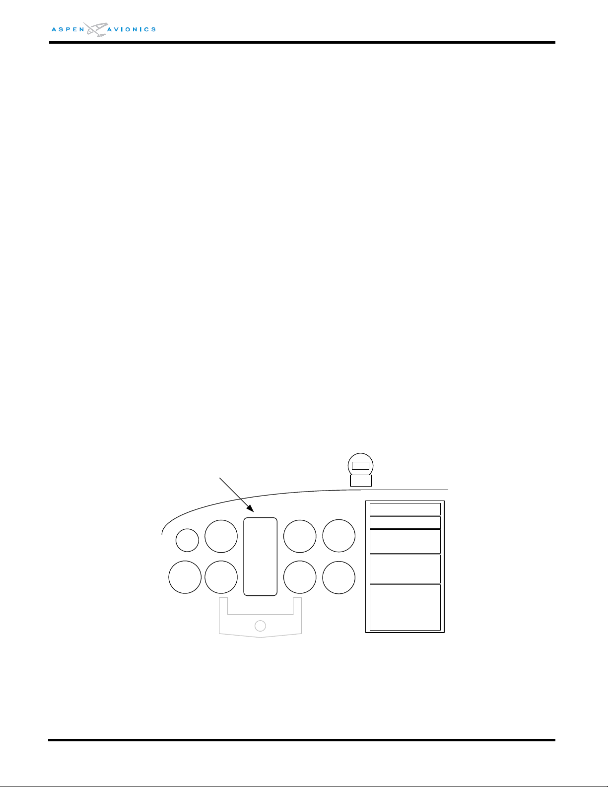
EFD1000 E5 Dual Electronic Flight Instrument (EFI) Install Manual
EFD
Typical EFD Location
6.7 Cooling
The EFD uses an integral fan for cooling. The area near the fan must be unobstructed to
permit maximum airflow through the unit. Venting and cooling air circulating behind the EFD
will improve heat dissipation and may improve equipment reliability, and is therefore a good
installation practice. The RSM, ACU, and Configuration Module have no cooling requirements.
6.8 EFD Installation
Mechanical installation of the EFD requires installing the included mounting bracket,
connecting a braided bonding strap between the EFD and panel, and installing pitot and static
connections to the two keyed quick release pressure fittings.
NOTE: To avoid damage to the equipment, do not place the EFD Display face down on the knobs.
6.8.1 EFD Mounting Location
The EFD must be mounted approximately centered in the instrument panel per 14CFR
23.1321(d). If the two existing instrument holes that contain the attitude indicator and
direction indicator are not exactly centered, but are the closest instruments to the center,
then that position is acceptable for mounting the EFD.
NOTE: Modification to the existing instrument panel is not authorized under this STC. Any
modification must be approved separately.
The EFD can be mounted on the non-pilot (typically right side) side of the instrument
panel if it is not for use by any required pilot during takeoff, initial climb, final approach,
and landing. Backup instruments are required on the pilot side only. See 14CFR 23.1311
and 14CFR 23.1321.
Figure 6-1: EFD Mounting Location
6.8.2 Surface Mounting the EFD as per Figure 6-2
The pre-drilled holes in the mounting bracket support both standard 3” round instrument
holes, and 3ATI square cutouts. The bracket is centered on the upper instrument hole.
DOCUMENT # 900-00041-001 PAGE 52-226 REVISION D
© Copyright 2019 Aspen Avionics Inc.
Page 53
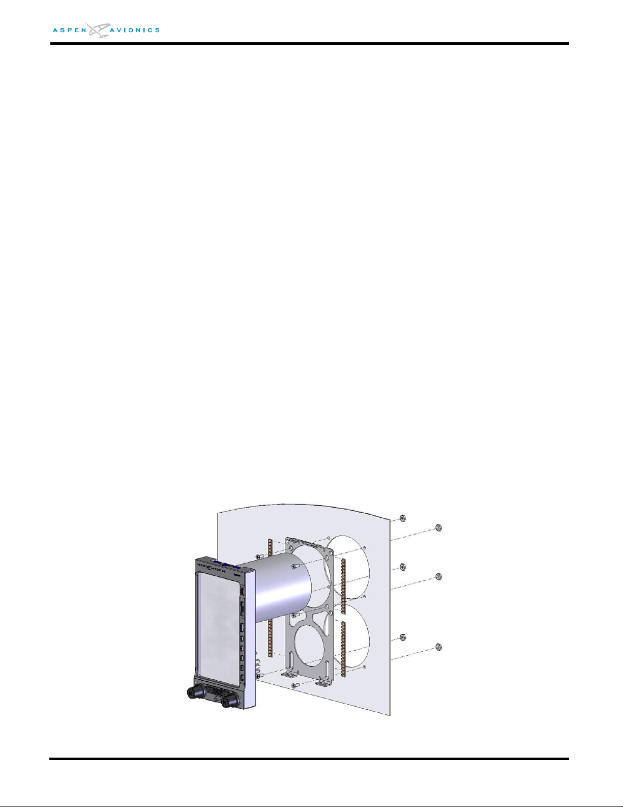
EFD1000 E5 Dual Electronic Flight Instrument (EFI) Install Manual
The lower portion of the bracket is provisioned with screw slots, allowing variable vertical
spacing configurations.
If the lower cutout is a 3ATI or other larger standard cutout, a commercially available
metal blanking plate should be used to flush fill the cutout. Use the EFD Mounting
Bracket as a template to cut the 2.10” diameter cutout for the fan and two 0.150”
diameter mounting holes. All cut edges should be treated to prevent corrosion.
Aircraft with tilted instrument panels of 20º or less can install the EFD flat against the
panel. The tilt will later be removed electronically in the system configuration using the
Panel Tilt Pitch Adjustment.
The EFD is attached to the instrument panel in 6 places with MS24693-S30 (#6-32
flathead screws), NAS1149FN632P (washers), and MS21044N06 (#6-32 Nuts). It is also
acceptable to use existing #6 nutplates.
1) Burnish the back of the instrument panel around one of the 6 mounting holes to allow
for bracket to instrument panel bonding through the screw/washer/nut.
2) Burnish the front side of the instrument panel in 4 locations that line up with the
copper EMI fingers of the bracket.
3) Loosely install the bracket with the upper two mounting screws/nuts/washers as
shown in the figure.
4) Use an inclinometer on the top of the EFD bracket with the aircraft level to make this
adjustment. It may be necessary to slot the existing holes to align the bracket in the
roll axis.
5) The EFD must be mounted within 0.0±2.0º of the zero degree roll “wings level” axis.
6) Fabricate an 8” bonding strap from braid and two ground lugs. Attach one ground lug
to a mounting screw on the backside of the panel (see Figure 6-10).
7) Install remaining EFD mounting bracket screws and nuts.
8) Tighten all six (6) mounting screws and nuts to 12 in-lbs. anchoring the bracket to
the panel.
Figure 6-2: EFD and Bracket Installation
DOCUMENT # 900-00041-001 PAGE 53-226 REVISION D
© Copyright 2019 Aspen Avionics Inc.
Page 54

EFD1000 E5 Dual Electronic Flight Instrument (EFI) Install Manual
Qty
Part Number
Description
1 per EFD
903-00007-001
Recess Mount EFD Installation Kit
4 per EFD
MS24693-S26
6-32 x 3/8”flat head screw, bracket to instrument
panel attachment.
1 per EFD
MS24693-S30
6-32 x ¾” flat head screw, bond strap attachment
1 per EFD
MS21044N06
6-32 Lock Nut, bond strap attachment
6.8.3 Recess Mounting the EFD as per Figure 6-4
These are partial instructions for accomplishing the aircraft modification to permit recess
mounting the EFD1000 E5 displays using Aspen Avionics Recess Mounting Kits. Recess
mounting of the EFD displays can be done for cosmetic reasons or for clearance when the
flight controls are in the full nose down position. This data, and the information found in
AC 43.13-2B Chapters 1, 2 and 11 normally is sufficient data to accomplish the
modification.
This section contains instructions for preparing the instrument panel to accept the EFD in
a recessed mounting. This data is approved for the structural aspects of the instrument
panel modification; however, by itself, it may not be sufficient data to address all aspects
of modifying the instrument panel of an aircraft. These instructions and the data in
AC43.13-2B chapters 1, 2 and 11 is normally sufficient data to complete the
modification. In some cases (for example only, if the instrument panel supporting
structure, structural attachments, or a structural instrument panel are modified) then
additional data will be required. In those cases where this data is insufficient then these
instructions, combined with additional data to accommodate individual differences in an
aircraft, can be presented to a Structural DER or Regulatory Authority for approval. If the
data package is satisfactory, the DER or Regulatory Authority will approve the data for use
in the modification of the instrument panel.
Once all necessary approved data to accomplish the panel mounting is obtained, and the
modification is accomplished, the EFD1000 E5 installation can proceed in accordance with
AML STC SA10822SC or other regulatory approval process.
One Recess Mounting Kit is required for each EFD display.
Table 6-2: Parts Required to Recess Mount each EFD
6.8.3.1 Recess Mount Modification Procedure
STEP 1 – Evaluate the Installation and Determine if Sufficient Approved Data is Available to
Proceed
Normally, the instructions in this section and in AC43.13-2B Chapters 1, 2 and 11 are
sufficient data to complete the modification. If the data is not sufficient, such as, for
example the instrument panel structural supports are affected or the panel itself
provides structural integrity to the airframe, then additional data must be developed
and approved. If additional data is required, collect and prepare the approved data
necessary to substantiate the alteration before modifying the aircraft.
DOCUMENT # 900-00041-001 PAGE 54-226 REVISION D
© Copyright 2019 Aspen Avionics Inc.
Page 55
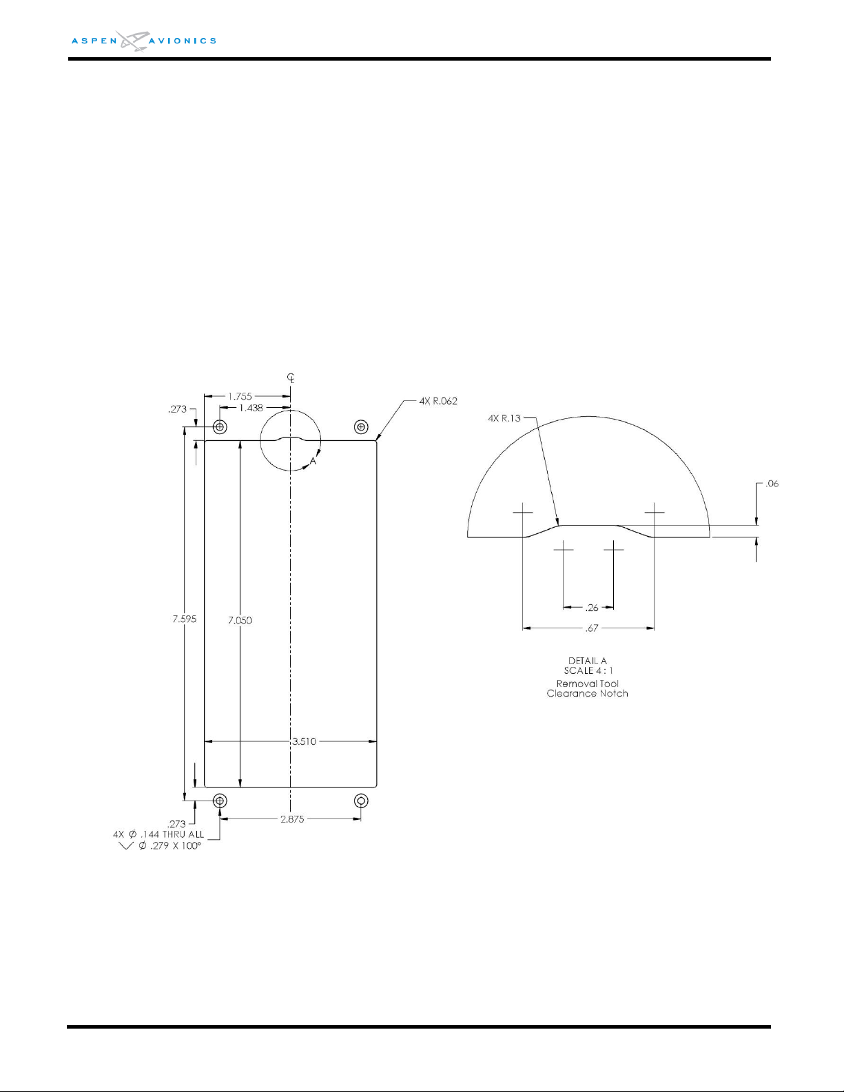
EFD1000 E5 Dual Electronic Flight Instrument (EFI) Install Manual
STEP 2 – Plan the Cutouts for the Instrument Panel in Accordance with the Cutout Location
Figures Below
Using the dimensions from Figure 6-3 as a guide determine the mounting location of
the bracket. Verify that no supporting structure is compromised. See AC43.13-2B.
STEP 3 – Obtain the Recess Mount Kit
One Kit is required for each EFD Display.
STEP 4 – Measure and Mark the EFD Cutout and Bracket Mounting Hole Locations
Using the dimensions from Figure 6-3 as a guide mark the EFD cutout and four bracket
mounting holes.
The clearance notch at the top (see detail “A”) is to permit a tool to be inserted to press
the EFD release mechanism and release the EFD from the mounting bracket
Figure 6-3: Single Display Recess Mount Cutout (inches)
STEP 5 – Cut out the EFD hole and Drill Four Mounting Holes
1) Remove instruments from surrounding area to be cut or remove instrument
panel from the aircraft. Verify nothing is in the way of the cutting tool before
making the cut.
2) Cut the display bezel opening and drill four bracket mounting holes (per EFD)
0.144” in diameter and countersink as required.
DOCUMENT # 900-00041-001 PAGE 55-226 REVISION D
© Copyright 2019 Aspen Avionics Inc.
Page 56
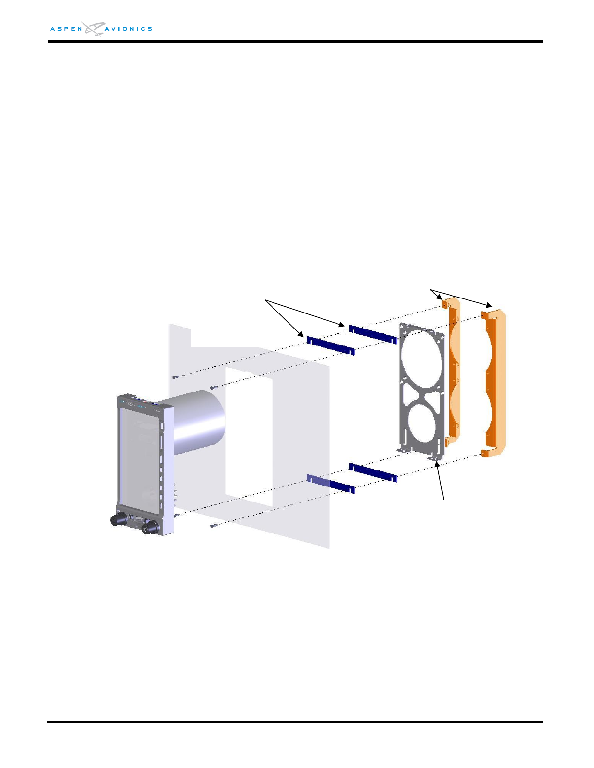
EFD1000 E5 Dual Electronic Flight Instrument (EFI) Install Manual
Spacers (A)
Two spacers are shown
for reference (0 to 4
may be required)
Recess Brackets (C)
3) Remove burrs and break sharp edges on the panel (0.005” – 0.015”).
4) Chemical conversion coat the bare aluminum and primer or paint as required.
STEP 6 – Install the Recess Mount Brackets and Hardware (Use Figure 6-4 for reference)
1) Fit the spacers (A) between instrument panel and recess brackets (C) as shown
in Figure 6-4, using four MS24693-S26 6-32 X 3/8 machine screws or pan
head screws may be used if that look is desired. Tighten all four mounting
screws and nuts to 12 in-lbs anchoring the brackets to the panel.
NOTE: Spacers (A) come in a strip of three which can be snapped apart. The thickness of the
instrument panel will determine how many spacers will be required. Instrument panels that are
1/8” thick should require one spacer while 1/16” panels may require up to four spacers to
provide the desired appearance.
2) Mount EFD Bracket (B) to Recess Brackets (C) using six MS24693-S24 6-32 X ¼
flat head machine screws.
3) Tighten all six mounting screws and nuts to 12 in-lbs.
DOCUMENT # 900-00041-001 PAGE 56-226 REVISION D
Figure 6-4: Single Display Recess Mount Bracket Installation
STEP 7 – Assemble and Attach the EFD Ground Strap
1) Fabricate one 8” bonding strap from braid with ground lugs at each end.
© Copyright 2019 Aspen Avionics Inc.
Page 57
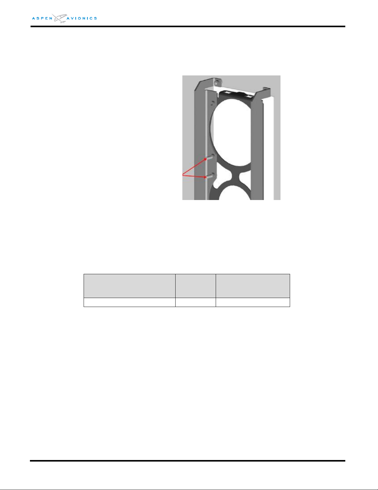
EFD1000 E5 Dual Electronic Flight Instrument (EFI) Install Manual
Direction of Pull
(push on bracket)
Load
Factor
Static Test Load
(load factor x EFD
weight)
Forward (toward firewall)
9.0g
9.0 x 2.9 = 26 lbs
Location of 6-32 X ¾” screw
for ground strap attachment
2) Insert a MS24693-S30 6-32 x ¾” flat head machine screw through either an
unused threaded insert or an existing EFD bracket attachment screw (see
Figure 6-5). Attach one end of the ground strap to this screw using a
MS21044N06.
Figure 6-5: Ground Strap Attachment Points
STEP 8 – Perform the Structural Load Test on the Bracket Installation
The following test is to structurally substantiate the bracket installation. The applied
static test load is determined using 2.9lbs for the EFD mass. See AC 43.13-2B for
additional Structural Data.
Table 6-3: Static Load Table
Use a block of wood or piece of aluminum that will cover the EFD bracket. This
ensures an even force is applied to the entire bracket at once. Place mechanical or
digital push/pull gauge against block and assert the static test load defined in the
table above for a minimum of 3 seconds. Ensure instrument panel and brackets show
no signs of permanent deformation.
NOTE: The recessed brackets are TSO’d and meet the sideward, upward, downward, and forward axis
load requirements of the EFD. Therefore only the forward axis is tested above to substantiate
the overall bracket installation.
DOCUMENT # 900-00041-001 PAGE 57-226 REVISION D
© Copyright 2019 Aspen Avionics Inc.
Page 58
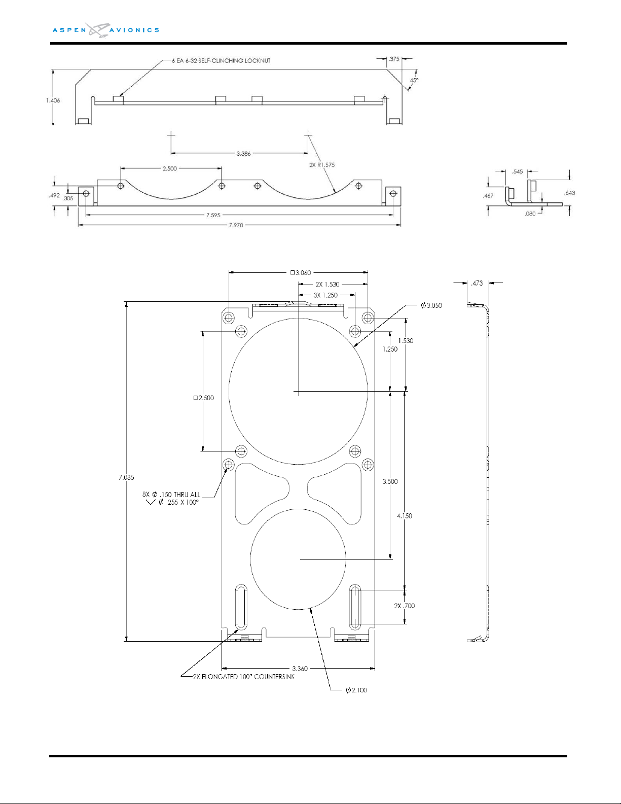
EFD1000 E5 Dual Electronic Flight Instrument (EFI) Install Manual
Figure 6-6: Recess Mounting Bracket Dimensions (inches)
Figure 6-7: EFD Mounting Bracket (inches)
DOCUMENT # 900-00041-001 PAGE 58-226 REVISION D
© Copyright 2019 Aspen Avionics Inc.
Page 59
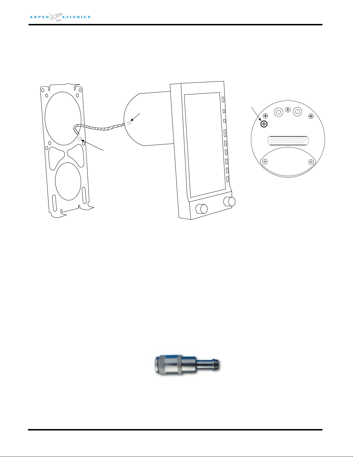
EFD1000 E5 Dual Electronic Flight Instrument (EFI) Install Manual
Ground to any mounting
hole backside of panel
Attach to screw below
and left of static port
Bonding Strap
Attachment Screw
Rear View of PFD
6.8.4 EFD Bonding Strap
An 8” or shorter braided bonding strap is required between the screw (below and left of
the static port- see Figure 6-8) on the backside of the EFD to a location on the backside
of the instrument panel using one of the mounting screws and nuts. Verify ≤ 3 milliohms
resistance to airframe ground at bonding strap connection point.
Figure 6-8: EFD Bonding Strap Connection
6.8.5 Pitot and Static Connections
Pitot and Static connections are made to the EFD1000 E5 via two keyed quick connect
fittings. These connections will typically require a “T fitting” to be installed in-line with
the existing altimeter and airspeed indicators.
The quick connectors are keyed such that they cannot be interchanged. Once the correct
quick connector is fastened to the pitot and static lines, they cannot be inadvertently
swapped on the rear of the EFD unit.
NOTE: The pitot quick connector will fit on the EFD static port but the static quick connector cannot
be inadvertently connected to the EFD pitot port due to the keying.
Each connector has a barbed fitting that accepts a 3/16” hose.
Figure 6-9: Pitot & Static Quick Connector
DOCUMENT # 900-00041-001 PAGE 59-226 REVISION D
© Copyright 2019 Aspen Avionics Inc.
Page 60
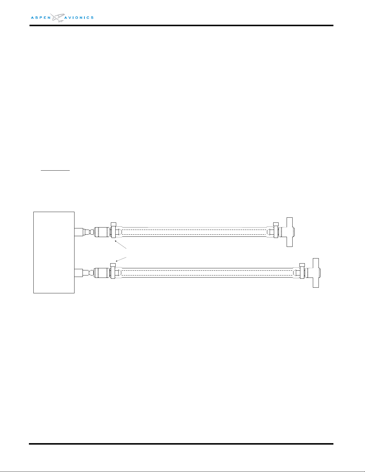
EFD1000 E5 Dual Electronic Flight Instrument (EFI) Install Manual
STATIC
PITOT
STATIC QUICK
CONNECTOR
P/N 275-00001-001
PITOT QUICK
CONNECTOR
P/N 275-00001-002
(KEYED – Yellow Band)
EFD1000
3/16” ID TUBING
PITOT
STATIC
“T” FITTING SPLICE INTO PITOT LINE
“T” FITTING SPLICE INTO STATIC LINE
HOSE CLAMP
3/16” ID TUBING
6.8.6 Quick Connector Installation
1) Insert “T” fitting into existing aircraft Pitot line and secure with the supplied hose clamp
(see Figure 6-10).
2) Connect a length of pitot line tubing between the “T” fitting and the “P” quick connector.
Verify the length of tubing can be installed with no drip loop and that it can be secured
away from flight controls. Secure each end with the supplied hose clamps.
3) Insert “T” fitting into existing aircraft Static line and secure with the supplied hose clamp
(see Figure 6-10).
4) Connect a length of static line tubing between the “T” fitting and the “S” quick connector.
Verify the length of tubing can be installed with no drip loop and that it can be secured
away from flight controls. Secure each end with the supplied hose clamps.
5) Secure pitot and static lines as necessary to prevent interference with other aircraft
structures and components and to prevent them from kinking when the EFD is slid in to
place.
CAUTION: Secure pitot and static lines so that they will not interfere with flight controls and are not
at risk of mechanical damage. The lines can soften when the EFD warms and should be
secured in a way that prevents the line from kinking.
Figure 6-10: Pitot & Static Line Connections
6.8.7 Leak Check Requirements
A pitot static leak check is required after the installation of the quick connectors and the
EFD1000 E5 is installed. The quick connectors are designed such that they seal when
disconnected.
DOCUMENT # 900-00041-001 PAGE 60-226 REVISION D
© Copyright 2019 Aspen Avionics Inc.
Page 61

EFD1000 E5 Dual Electronic Flight Instrument (EFI) Install Manual
6.9 RSM Installation
CAUTION: The RSM is an integral part of the attitude function of the AHRS. A stable and magnetically
quiet location for the RSM is essential for proper AHRS operation.
CAUTION: There are special considerations for mounting the RSM on composite, fabric and
pressurized aircraft. See sections 6.9.5 and 6.9.6.
The RSM includes magnetic flux sensors which is why it is important to locate the RSM as far
away from the cabin and baggage (or “hat rack”) compartment as practical as these areas may
have varying magnetic fields (baggage, passengers, etc.).
The RSM should not be mounted within 18 inches of a VHF Comm antenna, 6 inches of a GPS
or ELT antenna, or within 12 inches of an active traffic antenna or DME antenna.
The RSM should be mounted to a relatively flat surface such that there is less than .030” gap
surrounding the RSM when installed. The RSM must not be mounted to an excessively curved
area that could deform the RSM or aircraft skin.
The RSM must not be mounted within a composite fairing such as a fiberglass wingtip cover,
or vertical fin cover as these do not protect against direct lightning effects.
6.9.1 RSM Internal Mounting
Typically the RSM will be internally mounted within an area of the aircraft fuselage or wing
structure that is magnetically benign. For aluminum aircraft, the RSM may be mounted
anywhere inside the aluminum structure.
For composite or fabric covered aircraft (see Figure 6-12), the RSM must not be mounted
forward of the windscreen, or within 39” of the aft end of the fuselage. It may be mounted
within the wing but no closer than 39” of the wingtip. It must not be mounted within the
horizontal stabilizer, or within the vertical stabilizer. See Figure 6-12.
NOTE: If internally mounting the RSM a mounting plate must be locally fabricated and
approved separately. All mounting instructions for a magnetically quiet location still apply.
6.9.2 RSM Inverted or Bottom Mounting
See Figure 6-13. The–003 version of the RSM is designed for inverted bottom mounting.
This version may be mounted to any magnetically quiet area inside the fuselage or on the
underside of the fuselage. Mounting this RSM to the underside of an aerodynamic
surface, such as the wing or the horizontal stabilizer is not approved.
6.9.3 RSM External Top Mounting
See Figure 6-11. The RSM may be externally mounted if desired. One reason for doing
so is if an upgrade from an EFD1000 E5 to a EFD1000 Pro is being planned for. The Pro
has the options of internal GPS and OAT in the -001 RSM which require an external top
mount.
DOCUMENT # 900-00041-001 PAGE 61-226 REVISION D
© Copyright 2019 Aspen Avionics Inc.
Page 62

EFD1000 E5 Dual Electronic Flight Instrument (EFI) Install Manual
For a top external mount the preferred RSM installation area is a minimum of 12 inches
behind a typical baggage or (hat rack) compartment to no closer than 39” from the end of
the fuselage. The “Less Preferred” areas over the cabin should only be selected if
impossible to find an acceptable location within the “Preferred” area of Figure 6-11.
When externally mounted, the NO ZONE areas are hot zones for a lightning strike and are
not to be used for mounting the RSM. The RSM must not be mounted externally to the
wing, the top of the vertical stabilizer, the horizontal stabilizer, the fuselage forward of
the cabin, or within 39” of the tail as measured from the fuselage aft end as shown.
If it is impossible to find a suitable external mounting location in the preferred area, and
internal mounting is not possible, it may be permissible to mount the RSM above the
cabin. A location will need to be found that is a minimum of 18 inches from any small
cabin speakers or electronic device that can cause compass fluctuations. Large cabin
speakers may cause RSM interference at distances up to 3 feet. Use the procedure in
Section 6.9.4 to locate a quiet area. During operation of the electrical systems,
concentrate on those devices that are in the cabin and within the headliner. Be aware
that headsets and other items worn by and operated by the flight crew and passengers
could potentially interfere with the RSM. Typically this would be when the headset is
within 12” of the RSM location. Find a location that cannot be affected by passenger and
flight crew headsets while seated or moving about the cabin.
DOCUMENT # 900-00041-001 PAGE 62-226 REVISION D
© Copyright 2019 Aspen Avionics Inc.
Page 63
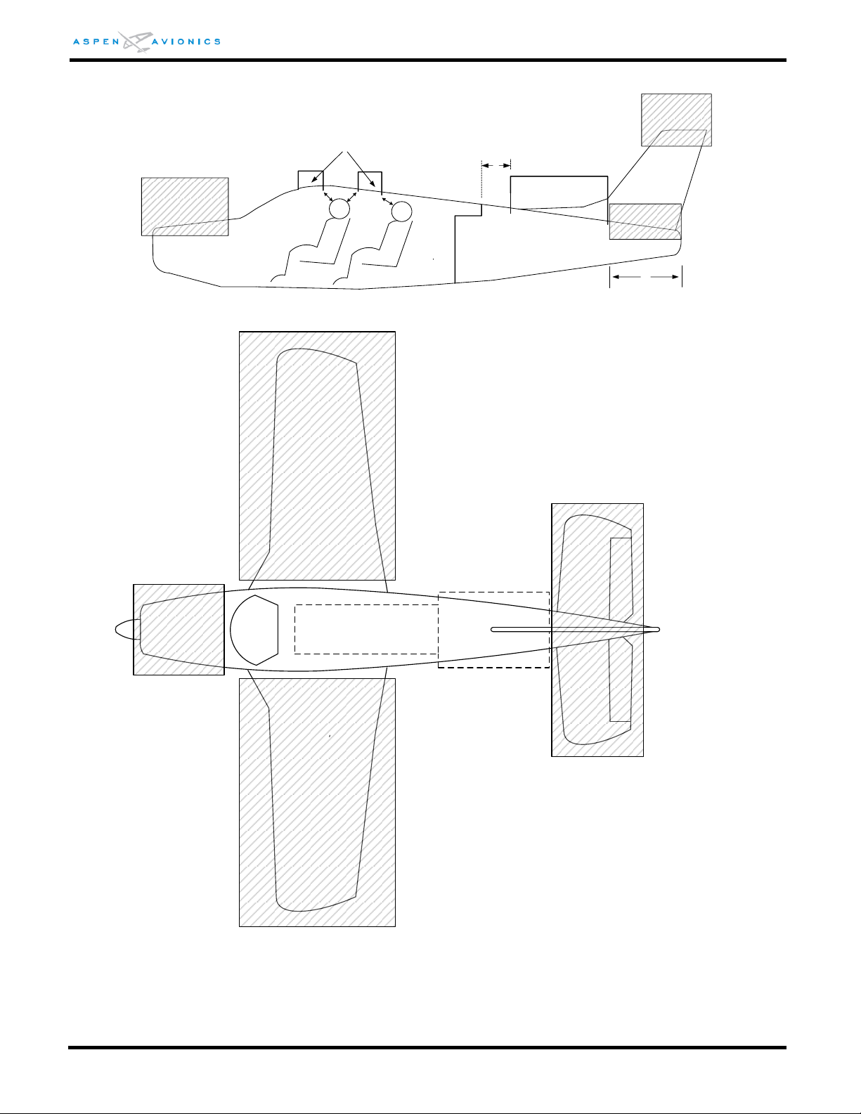
EFD1000 E5 Dual Electronic Flight Instrument (EFI) Install Manual
12"
Preferred Area
Hat Rack
Baggage
Compartment
NO ZONE
NO ZONE
Less Preferred Locations
(See Note)
12" minimum
separation
39"
NO ZONE
12" minimum
separation
NO ZONE
NO ZONE
NO ZONE
Preferred Area
Less
Preferred Area
(See Note)
NO ZONE
Figure 6-11: RSM-External Mounting Locations (Top/Side View) – all aircraft types
DOCUMENT # 900-00041-001 PAGE 63-226 REVISION D
© Copyright 2019 Aspen Avionics Inc.
Page 64
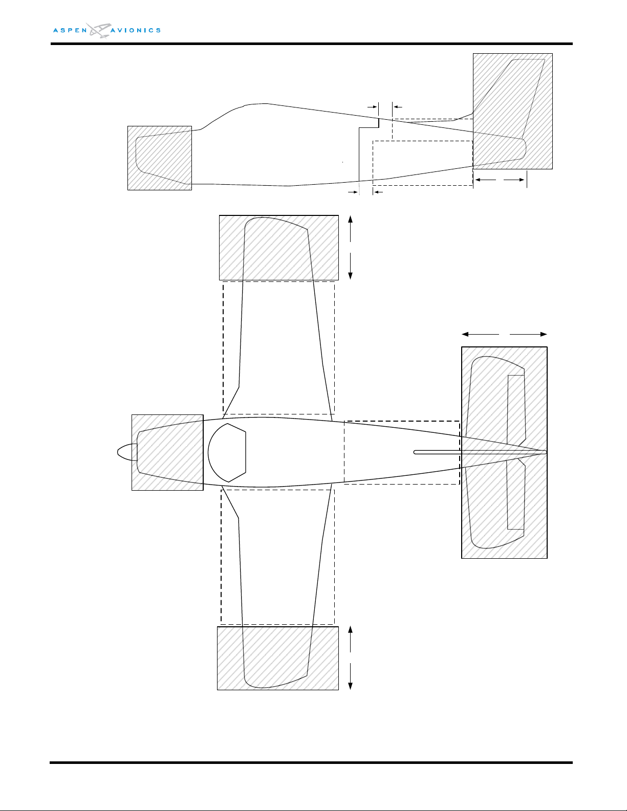
EFD1000 E5 Dual Electronic Flight Instrument (EFI) Install Manual
Hat Rack
Baggage
Compartment
NO ZONE
39"
NO ZONE
Acceptable Internal
Mount Area
Composite/Fabric
12"
12"
NO ZONE
NO ZONE
Acceptable Internal
Mount Area
Composite/Fabric
NO ZONE
39"
NO ZONE
39" 39"
Acceptable Internal
Mount Area
Composite/Fabric
Acceptable Internal
Mount Area
Composite/Fabric
Figure 6-12: RSM Internal Mounting Locations – Composite/Fabric Aircraft
DOCUMENT # 900-00041-001 PAGE 64-226 REVISION D
© Copyright 2019 Aspen Avionics Inc.
Page 65
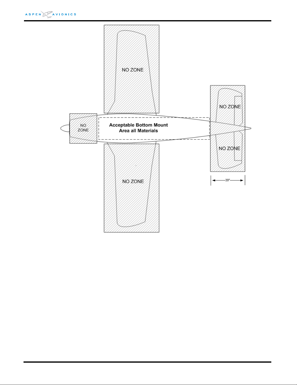
EFD1000 E5 Dual Electronic Flight Instrument (EFI) Install Manual
Figure 6-13: RSM-003 External Mounting Locations (Bottom view)
6.9.4 Proposed RSM Location Check
The installer must determine the best RSM location given the above factors. With proper
training and careful application, a navigation quality handheld compass (i.e., hiking
compass) can be used to find a magnetically quiet area free from the effects of magnetic
disturbances from flight controls, autopilot servos, strobes, or any other large magnetic
field appliance. The HMR2300 Smart Digital Magnetometer is a more effective tool to
properly choose an RSM location, it detects magnetic fields with more precision and
should be used with TechNote TN2010-01 to identify RSM locations that are free from
magnetic interference.
The RSM can detect magnetic fields in three dimensions. This means that magnetic
influences below the RSM can also affect performance. Be sure to evaluate potential
magnetic influences above and below the RSM.
DOCUMENT # 900-00041-001 PAGE 65-226 REVISION D
© Copyright 2019 Aspen Avionics Inc.
Page 66

EFD1000 E5 Dual Electronic Flight Instrument (EFI) Install Manual
Magnitude
Total Gauss Field (TG)
(1)
Aircraft Equipment or Structure
Suggested Separation to RSM
+/- 20 higher than
Magnitude (TG)
(base
)
Ferrous fasteners (non-magnetized)
6 inches
+/- 20 to +/-30 higher
than Magnitude (TG)
(base
)
Larger ferrous parts
Unknown – suggest 12 inches
700 - 1000 (too high)
or
300 - 400 (too low))
Batteries, Steel Tube,
non-magnetized structure/equipment
12 inches
NOTE: Changes to the magnetic field around the RSM can affect the RSM calibration and require
revalidation of the RSM performance.
Known sources of interference include (but are not limited to) the following types of
material located near the RSM (normally, these materials within 12 inches can cause
interference):
Steel-wound aircraft air-ducting
Steel hose clamps
Steel control cables and turnbuckles
Steel tube – especially at the welds
Magnetized or magnetic hardware
Servos
Trim motors
Poor bonding of electrical connections
Blower motors
Cockpit or cabin speakers
Known sources of interference due to electrical noise include (but are not limited to) the
following. Be sure to check for interference with the following systems operating:
Servos
Alternator/Generator and cabling to aircraft battery
Blower motors
Strobes, beacons
Pulse equipment (DME, transponder active TAS, TCAS)
Air conditioner
Electrical ground current through the aircraft skin
The following Table shows minimum separation distances from common sources of interference that
have resulted in an acceptable magnetic environment. These are guidelines and will not result in
satisfactory performance in every situation. Magnetic influence is somewhat additive, so multiple
sources of interference may require greater separation distances than shown here.
DOCUMENT # 900-00041-001 PAGE 66-226 REVISION D
© Copyright 2019 Aspen Avionics Inc.
Page 67

EFD1000 E5 Dual Electronic Flight Instrument (EFI) Install Manual
Magnitude
Total Gauss Field (TG)
(1)
Aircraft Equipment or Structure
Suggested Separation to RSM
1200 – 1800
(extremely high)
or
200 -300
(extremely low)
Servo Motors, Fan Motors, magnetized-
steel tube/welds/Steel wound ducting/
fasteners
15 inches
Greater than 1800
Speakers
24 inches plus
Note: The separations above are not absolute and further minimum distances may be required!
The installing dealer is responsible for choosing a proper RSM location.
(1)
This column is only
applicable to the HMR2300 tester.
Place the HMR or small handheld compass in the proposed RSM mounting location and
move the compass around the location looking for needle deflection. There should be no
more than 2º of compass needle movement within an area 18” x 18”x 18” around the
proposed location. Should the compass show excessive needle movement it would be
required to find a new location or, if feasible, treat the affected area with a degaussing
coil. Contact your authorized dealer for information on obtaining or using a handheld
degaussing coil. A degaussing coil can be purchased at most audio and video stores.
Operate flight controls from stop to stop and verify no more than 2º of compass needle
movement. Should the compass show excessive needle movement it would be required
to find a new location or degauss the flight control cables and or flight control hardware.
Operate all electrical systems. The compass needle should not deflect more than 2
degrees during testing.
If a location cannot be found with less than 2 degrees of deflection then the electrical
device causing the interference will need to be determined. The device causing the
interference may need to be re-bonded or the wiring may need to be relocated.
If the HMR or compass does not show any deflection from electrical or mechanical
sources, then that location should be acceptable to mount the RSM. The installer is
responsible to choose an RSM location that provides satisfactory heading accuracy.
6.9.5 Pressurized Aircraft
On pressurized aircraft it may be necessary for the RSM wiring to penetrate the aircraft
pressure vessel. The installer is responsible for obtaining proper documentation and FAA
approvals from either the airframe manufacturer or from a DER or FAA field office for any
penetrations of the pressure vessel or bulkhead.
NOTE: Penetration of the pressure vessel is not approved under this STC and will require separate
approval.
NOTE: Mounting the RSM on the pressure vessel is beyond the scope of this STC and requires
separate approval.
DOCUMENT # 900-00041-001 PAGE 67-226 REVISION D
© Copyright 2019 Aspen Avionics Inc.
Page 68
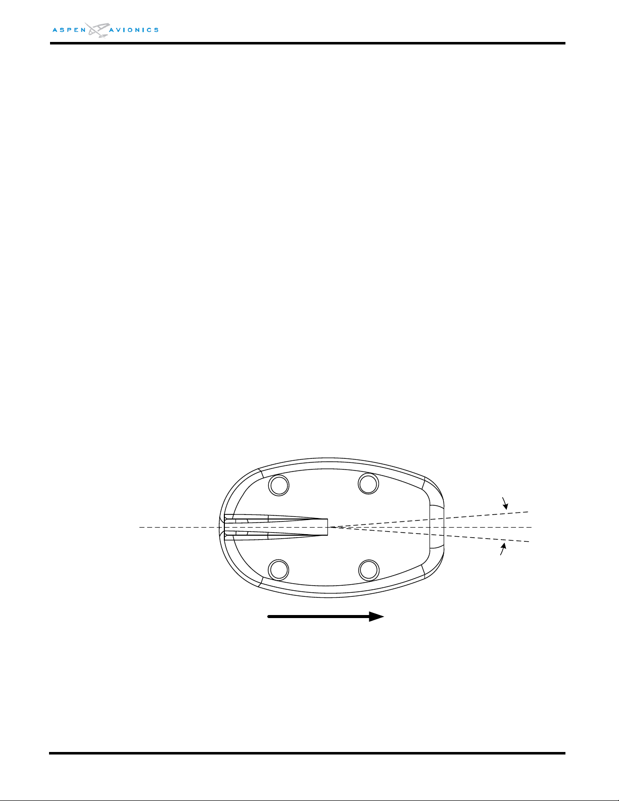
EFD1000 E5 Dual Electronic Flight Instrument (EFI) Install Manual
Parallel line to
aircraft center line
4º
4º
FWD
+/- 4º Max Alignment error
from aircraft centerline
6.9.6 RSM Mounting on Non-Metal or Damage-Tolerant Design Aircraft
Approval for the structural aspects of mounting the RSM to a composite or fabric skinned
aircraft, including consideration for the direct effects of lightning, is beyond the scope of
the EFD1000 E5 AML STC. Separate FAA approval for structural and lightning direct
effects considerations is required before mounting the RSM on these aircraft types.
The installation information for the RSM in this manual is satisfactory to meet the
requirements for the direct effects of lightning for all metal aircraft.
It is not possible to determine the lightning direct effects on equipment mounted
internally in composite and fabric aircraft. Therefore, the only acceptable areas for RSM
internal mounting are shown in Figure 6-12. The same bonding requirements for an
external mounting must be adhered to.
Though separate approval must be obtained for the RSM structural and, in the case of
fabric and composite aircraft, lightning direct effects; installation of the remaining
EFD1000 E5 system components is approved under the EFD1000 E5 AML-STC. This
includes HIRF and lightning induced transient susceptibility approval of the EFD1000 E5
system installation (i.e. display, RSM, CM, ACU, and associated wiring).
6.9.7 RSM Mounting Angles
For RSM mounting the following maximum mounting angles apply.
NOTE: For aircraft operating in the latitudes above 55N or in the southern fourth of Australia it is
recommended that the RSM mounting angles be at 5 degrees or less.
6.9.7.1 Longitudinal Axis
Figure 6-14: RSM Top View longitudinal Alignment
6.9.7.2 Pitch Axis
Maximum fore and aft tilt is in relation to the aircraft waterline. An aluminum shim
might be required to keep orientation within limits (see Section 6.9.11 for shim
fabrication).
DOCUMENT # 900-00041-001 PAGE 68-226 REVISION D
© Copyright 2019 Aspen Avionics Inc.
Page 69
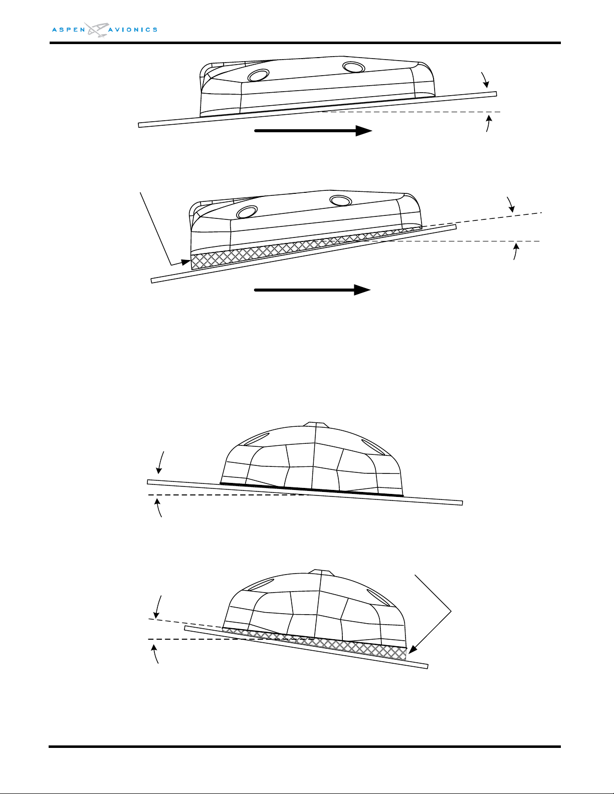
EFD1000 E5 Dual Electronic Flight Instrument (EFI) Install Manual
10º Max Fore or Aft Tilt
FWD
10º Max Fore or Aft Tilt
FWD
Aircraft Waterline
SHIM
(Installer Fabricated if necessary)
Aircraft Skin
Front View
10º Max Tilt
Front View
10º Max Tilt
SHIM
(Installer Fabricated if necessary)
Figure 6-15: RSM Fore or Aft Max Tilt
Figure 6-16: RSM Fore or Aft Max Tilt (Shim installed)
6.9.7.3 Roll Axis
Maximum side-to-side tilt is 10 degrees in relation to wings level. An aluminum shim
might be required to keep orientation within limits (see Section 6.9.11 for shim
fabrication).
Figure 6-17: RSM Side to Side Max Tilt
Figure 6-18: RSM Side to Side Max Tilt (Shim installed)
DOCUMENT # 900-00041-001 PAGE 69-226 REVISION D
© Copyright 2019 Aspen Avionics Inc.
Page 70
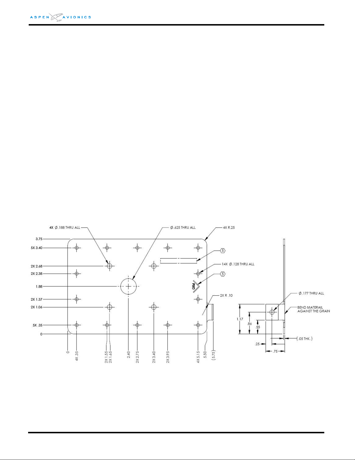
EFD1000 E5 Dual Electronic Flight Instrument (EFI) Install Manual
6.9.8 RSM External Mount – Aluminum Skin
This STC approves the use of the doubler shown in Figure 6-19 for Aluminum Skinned
aircraft only. Mounting the RSM externally to a composite or fabric aircraft is not
approved by this STC and will require that the installer obtain separate approval of the
RSM mounting on these classes of aircraft. After the RSM mounting has been approved,
this STC may be subsequently installed.
The doubler may be purchased from Aspen under P/N 503-00015-001 or may be
installer fabricated using the dimensions and rivet holes as shown. Should the installer
wish to deviate from this doubler in size, rivet count, rivet spacing, or doubler thickness,
they are required to seek separate approval.
6.9.8.1 RSM Doubler Fabrication
1) Determine the thickness of the aircraft skin.
2) For aircraft skins 0.050” thick and less the doubler should be made from 0.050”
material or optionally Aspen P/N 503-00015-001 doubler may be used. For
aircraft skins thicker than 0.050 the doubler should be made from material the
same thickness as the aircraft skin.
3) Fabricate the doubler from 2024-T3 AMS-QQ-A-250/5 to the dimensions in
Figure 6-19, Tolerances ± 0.030.
Figure 6-19: RSM Doubler P/N 503-00015-001
NOTE: The tab for the RSM shield ground lug connection may be bent as shown or the entire forward
edge may be extended and bent down as a tab.
4) Remove burrs and break sharp edges (0.005” – 0.015”).
5) Finish with Alumiprep Etch and Alodine Conversion Coating.
DOCUMENT # 900-00041-001 PAGE 70-226 REVISION D
© Copyright 2019 Aspen Avionics Inc.
Page 71
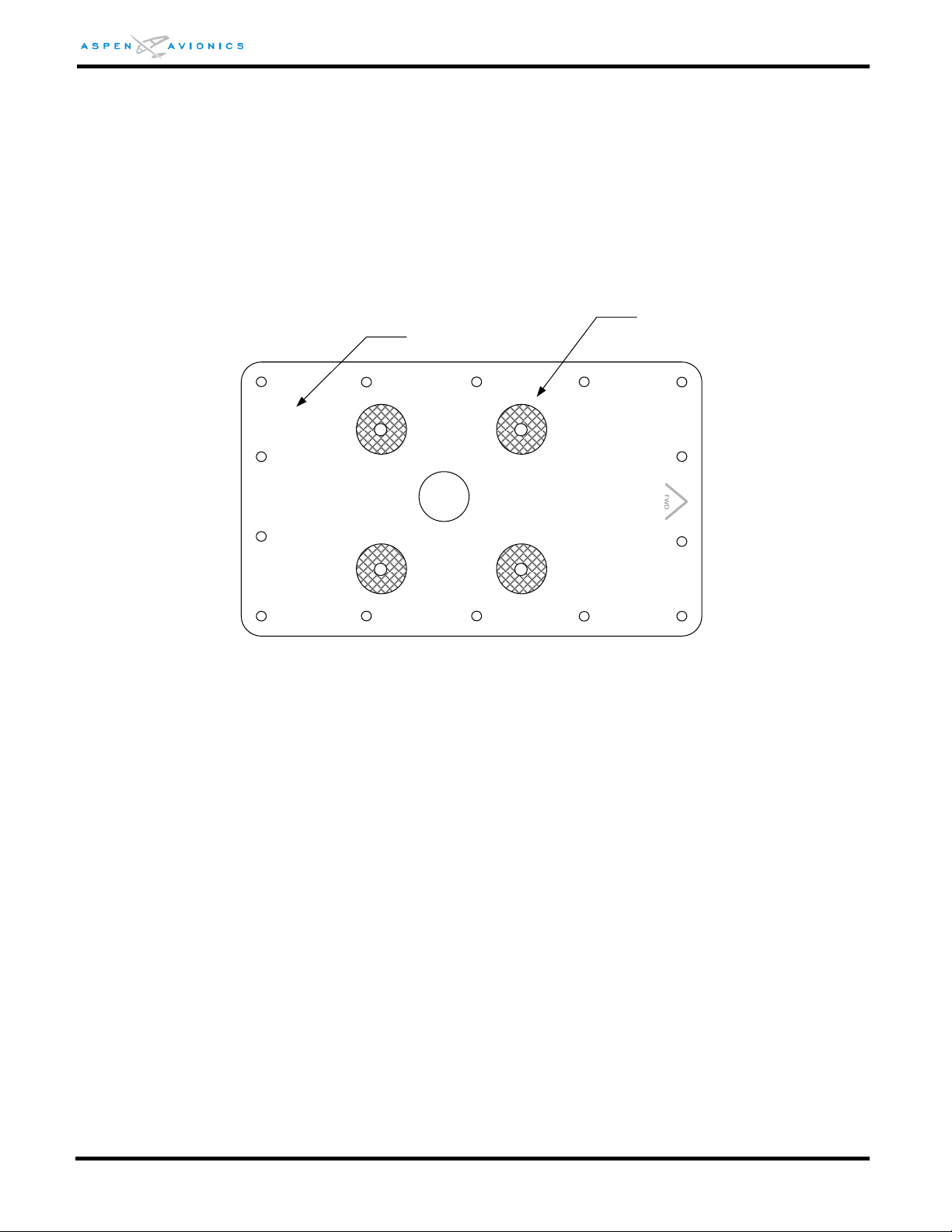
EFD1000 E5 Dual Electronic Flight Instrument (EFI) Install Manual
FWD
Mask four (4) places
Do not primer
Allows for electrical bond
between washer and doubler.
Down side
Primer
6) Mask around the four (4) mounting holes the diameter of the mounting washers or
1/2" on the down side of the doubler (see Figure 6-22). Prime that side with epoxy
primer per MIL-P-23377. Do not prime the side that faces the aircraft skin. This
allows for a doubler to aircraft skin bond and mounting washer to doubler bond.
7) Mark forward direction on doubler because pattern is not symmetrical.
8) Using the doubler as a template match drill holes in aircraft fuselage at location
determined from Section 6.9.4. Doubler must be aligned to the longitudinal axis of
the aircraft to within ±4º (see Figure 6-14).
Figure 6-20: Masking of Doubler
9) Remove burrs and break sharp edges on the aircraft skin (0.005” – 0.015”)
10) Burnish the aircraft skin on the inner surface in the area where the doubler will
mount. Apply Alodine 1201 and do not prime.
11) The doubler is attached to the inside surface of the aircraft skin with solid rivets.
12) For aircraft skin less than 0.032 thick install with MS20470AD4 protruding head
rivets.
13) For aircraft skin thickness of 0.032 install with NAS1097AD4 rivets flush in the
fuselage skin. Carefully control the countersink depth to not knife-edge the
fuselage skin.
14) For aircraft skin thicknesses 0.040 to 0.050 install with NAS1097AD4 rivets flush in
the fuselage skin.
15) For aircraft skins 0.063 or thicker install with NAS1097AD5 rivets flush in the
fuselage skin.
DOCUMENT # 900-00041-001 PAGE 71-226 REVISION D
© Copyright 2019 Aspen Avionics Inc.
Page 72

EFD1000 E5 Dual Electronic Flight Instrument (EFI) Install Manual
Description
8-32 Brass screw 1¼” MS35214-47
Brass locking nuts MS21044B08 (formerly AN365-B832)
Brass Washer NAS1149B0832H (formerly AN960-B8)
Figure 6-21: Doubler Installation
6.9.9 RSM Internal Mount
The installer must use a suitable existing shelf or fabricate a suitable mounting bracket
for internally mounting the RSM. Use AC43.13-2B Chapter 1 for additional structural
data.
6.9.10 RSM Installation
CAUTION: Do not use a magnetic tipped or electric screwdriver to mount the RSM as this may
magnetize the RSM and cause heading errors.
CAUTION: Only non-ferrous mounting hardware can be used (i.e., screws, nuts, washers, nutplates)
to mount the RSM. Use of any ferrous hardware may cause compass errors. The supplied
Brass hardware should be used.
NOTE: The RSM contains a sensitive magnetometer. Nearby ferrous components or hardware can
magnetize the RSM and/or cause erroneous indications.
1) It is not required to remove aircraft surface paint below RSM unless an aluminum shim was
required on extreme mounting angles. The shim must be bonded to the fuselage. Bonding
of RSM is through four (4) mounting screws to doubler.
2) Install ring terminal to RSM shield ground wire.
3) Install RSM on aircraft and secure using four (4) screws, four (4) washers, and four (4) nuts
as identified below. Installer may substitute non-ferrous nut plates for washers and nuts
provided the nutplates are attached to the doubler only and not the aircraft skin.
Table 6-4: RSM Mounting Hardware
DOCUMENT # 900-00041-001 PAGE 72-226 REVISION D
© Copyright 2019 Aspen Avionics Inc.
Page 73
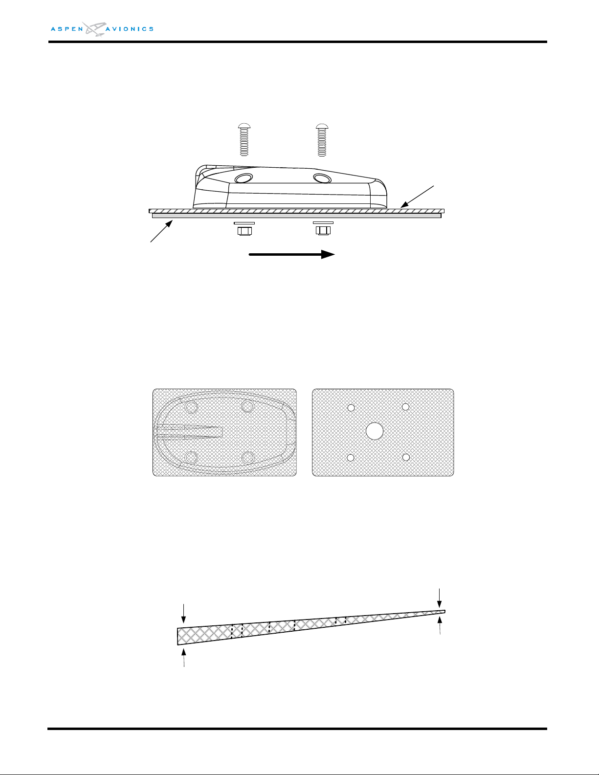
EFD1000 E5 Dual Electronic Flight Instrument (EFI) Install Manual
Doubler
(installer fabricated)
Aircraft Skin
FWD
No Thinner than 0.040"
No Thicker than 3/8"
4) Torque hardware to 12-15 in-lbs. Do not over-torque the hardware as it may cause the
RSM housing to crack.
5) Attach ring terminal to ground stud on RSM doubler tab.
6) Apply a bead of non-corrosive sealant around the RSM.
Figure 6-22: RSM Mounting
6.9.11 RSM Shim Fabrication (if necessary)
If the RSM exceeds the mounting limits of Section 6.9.7 a shim will be required.
Fabricate a shim with the dimensions of the RSM baseplate. Optionally the shim can be
made square and slightly larger than the RSM baseplate for ease of construction (see
Figure 6-23).
Figure 6-23: Example Shim Top View
The shim must not exceed the minimum and maximum thickness as shown in Figure
6-24. Use of a thicker shim is acceptable but not approved under this STC. A thicker
shim will require a local approval.
Figure 6-24: Example Shim Side View
DOCUMENT # 900-00041-001 PAGE 73-226 REVISION D
© Copyright 2019 Aspen Avionics Inc.
Page 74

EFD1000 E5 Dual Electronic Flight Instrument (EFI) Install Manual
Epoxy Primer
Both Sides
Do not Prime
Mask Off
Both Sides
1) Use RSM doubler as a template to mark shim stock.
2) Fabricate shim from 2024-T3 aluminum with the four (4) mounting holes and 0.625”
cable pass-thru drilled through.
3) Remove burrs and break sharp edges (0.005” – 0.015”)
4) Finish with Alumiprep Etch and Alodine Conversion Coating.
5) Mask off top side of shim 1/4” inside mounting surface of RSM and mask off a similar
area on the bottom so that these areas remain Alodine only (see Figure 6-25). Prime
unmasked areas with epoxy primer per MIL-P-23377. Paint to match aircraft color if
desired.
Figure 6-25: Masking of Shim for Priming
6) The shim must be bonded to the aircraft skin by removing the paint and prepping the
aircraft surface where the shim and RSM will be mounted. Remove paint ½” inside the
outer footprint of the RSM mounting location. Burnish the aircraft skin and apply Alodine
1201, do not prime.
7) Sandwich the shim between the aircraft skin and the RSM following the RSM installation
procedure in Section 6.9.10.
8) Apply non-corrosive sealant around shim and RSM.
6.10 ACU/ACU2 Installation
The ACU/ACU2 has no user interface, and therefore can be remote mounted. The optimum
mounting location is an area that minimizes wire runs to interfacing equipment. This typically
means near the autopilot computer if installed.
When mounting the ACU/ACU2 find a location in the aircraft of known load carrying
capabilities such as:
Existing Avionics Shelf
Baggage compartment
Radio Rack
Cockpit Floor
DOCUMENT # 900-00041-001 PAGE 74-226 REVISION D
© Copyright 2019 Aspen Avionics Inc.
Page 75
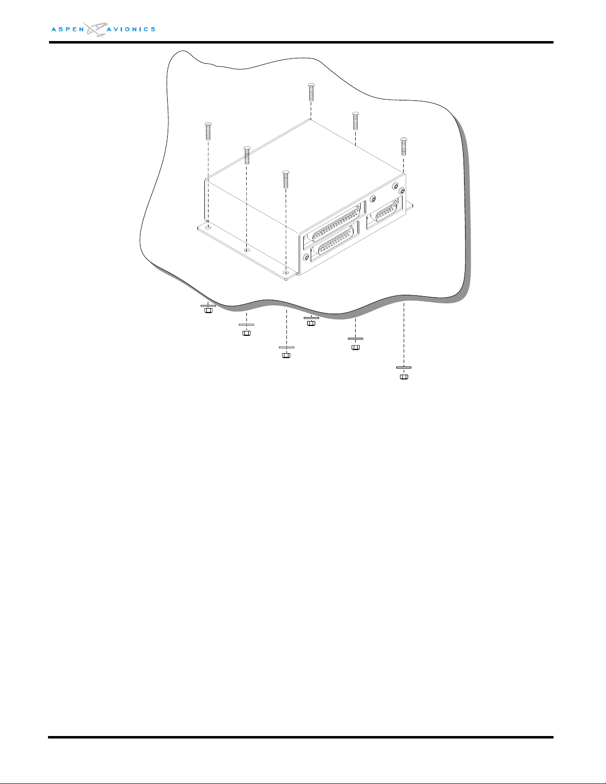
EFD1000 E5 Dual Electronic Flight Instrument (EFI) Install Manual
Figure 6-26: ACU/ACU2 Mount to Flat Metal Shelf
6.10.1 ACU/ACU2 Mounting
Mount the ACU to existing shelf in any orientation using six (6) MS35206 #8-32 screws,
six (6) NAS1149FN832P washers, and six (6) MS21044N08 #8-32 self-locking nuts.
Tighten nuts to 12 in-lbs.
Installation of the ACU/ACU2 must be in accordance with AC43.13-2B, Chapter1
Paragraphs 100 to 114, pages 1 to 8. An unpainted surface of the ACU case must be
bonded to aircraft ground either through mounting to a metal shelf or with an installer
fabricated bonding strap of wire braid or single stranded wire no more than 12 inches in
length. Attach ground lug of bonding strap to one of the mounting screws if required.
Refer to AC 43.13-1B paragraphs 11-187 to 11-190, pages 11-73 to 11-79 for
additional bonding information.
Verify ACU case to airframe ground has ≤ 3 milliohms of resistance.
Should a shelf or bracket need to be fabricated in order to install the ACU it is beyond the
scope of this STC and will require separate FAA approval for that modification.
DOCUMENT # 900-00041-001 PAGE 75-226 REVISION D
© Copyright 2019 Aspen Avionics Inc.
Page 76
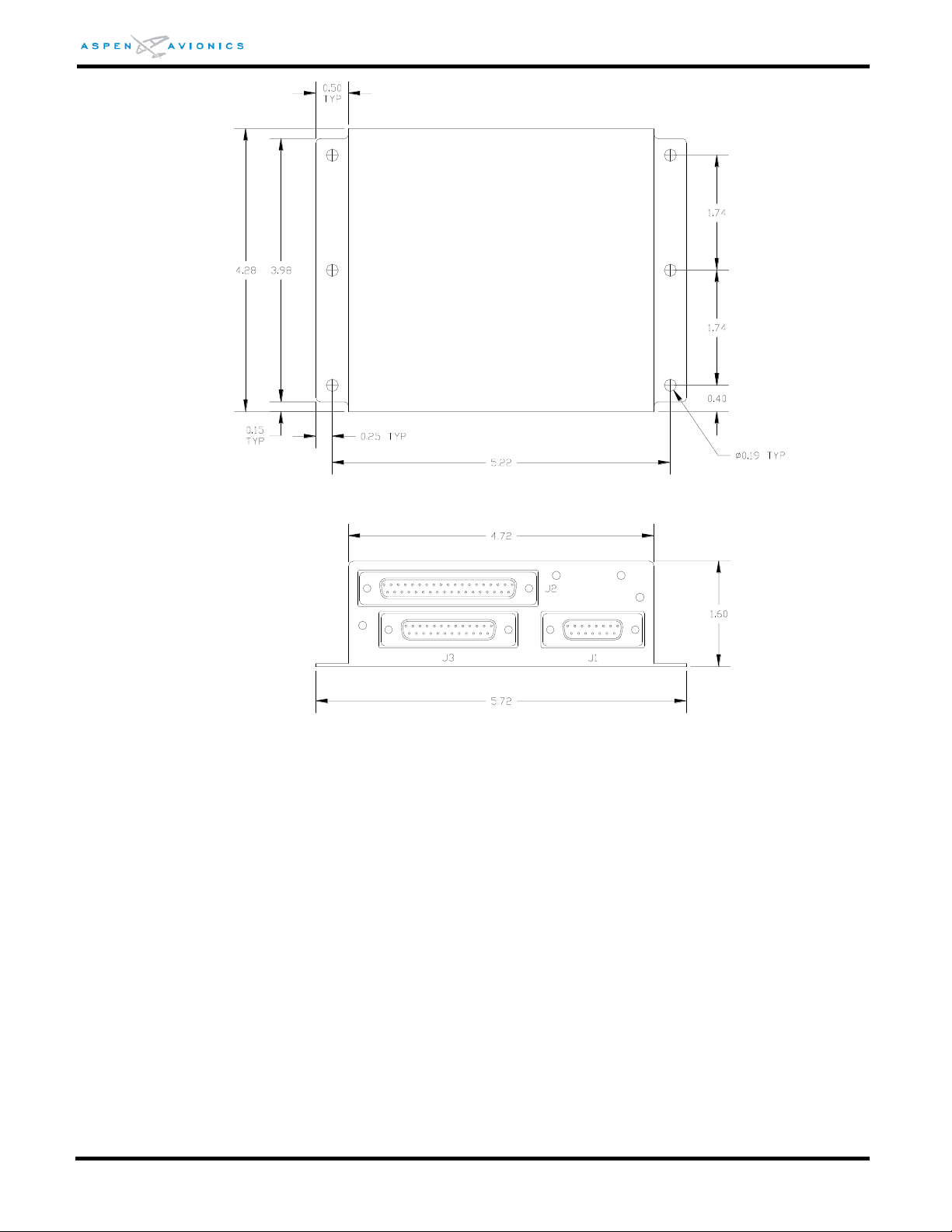
EFD1000 E5 Dual Electronic Flight Instrument (EFI) Install Manual
15
20
1
1
14
37
19
13
25
1
9
8
Figure 6-27: ACU Dimensions (inches)
DOCUMENT # 900-00041-001 PAGE 76-226 REVISION D
© Copyright 2019 Aspen Avionics Inc.
Page 77
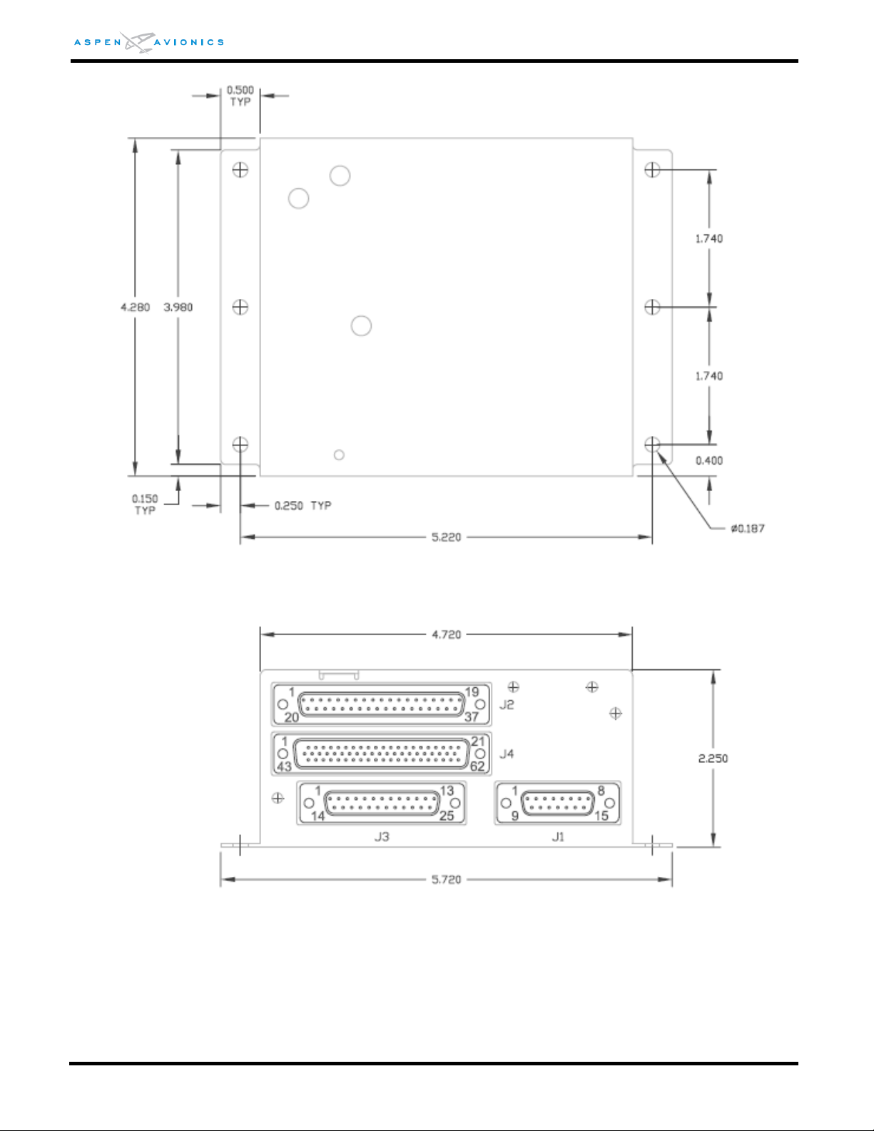
EFD1000 E5 Dual Electronic Flight Instrument (EFI) Install Manual
Figure 6-28: ACU2 Dimensions (inches)
DOCUMENT # 900-00041-001 PAGE 77-226 REVISION D
© Copyright 2019 Aspen Avionics Inc.
Page 78
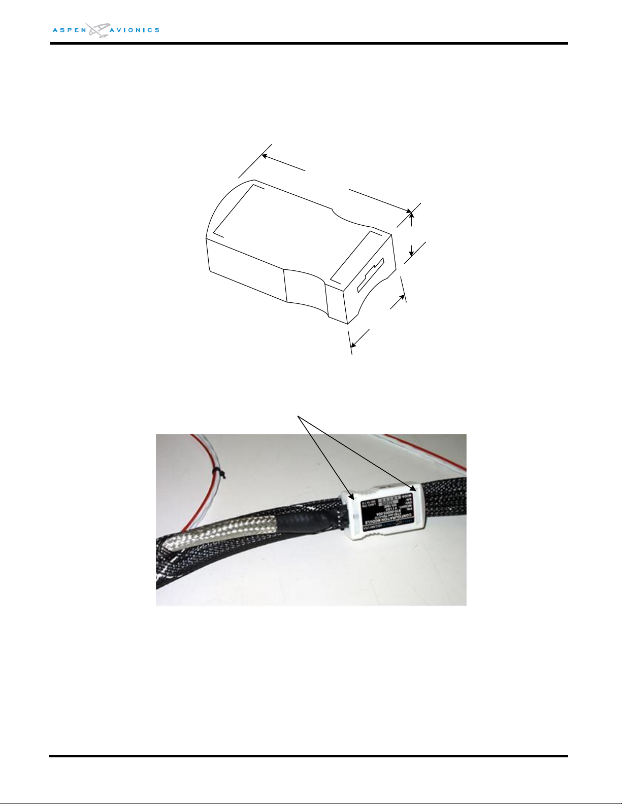
EFD1000 E5 Dual Electronic Flight Instrument (EFI) Install Manual
1
.
85
in
1
.
0
in
0.55 in
Cable Tie two (2) places
6.11 Configuration Module Installation
The Configuration Module will be cable tied to the EFD wire harness. Leave just enough slack
in the cable ties so that the configuration module can slide along the EFD cable. This will
prevent strain on the configuration module connector while the EFD harness is manipulated
during installation and subsequent removal/replacement.
Figure 6-29: Configuration Module Dimensions (inches)
Figure 6-30: Configuration Module Tie Wrapped to Harness
DOCUMENT # 900-00041-001 PAGE 78-226 REVISION D
© Copyright 2019 Aspen Avionics Inc.
Page 79

EFD1000 E5 Dual Electronic Flight Instrument (EFI) Install Manual
THIS PAGE IS INTENTIONALLY LEFT BLANK
DOCUMENT # 900-00041-001 PAGE 79-226 REVISION D
© Copyright 2019 Aspen Avionics Inc.
Page 80

EFD1000 E5 Dual Electronic Flight Instrument (EFI) Install Manual
Component
Current Draw (amps)
EFD1000 E5 (EFD)
2.4 nominal @ 28Vdc
4.8 nominal @ 14Vdc
RSM – Remote Sensor Module
Current Draw included in EFD1000
E5
ACU – Analog Converter Unit
0.5 nominal @28Vdc
1.0 nominal @ 14Vdc
ACU2 – Analog Converter Unit 2
0.5 nominal @ 28Vdc
1.0 nominal @ 14Vdc
Configuration Module
Current draw included in EFD1000
E5
7 Electrical Installation
7.1 Electrical Load Analysis
Perform an electrical load analysis to verify the aircraft complies with FAR 23.1351(a) using
the current draw of each installed component as determined from Table 7-1 below.
Table 7-1: Current Draw
7.2 Electrical Installation
7.2.1 EFD1000 E5
A dedicated 7.5 amp pull type circuit breaker and switch or breaker/switch combination
for the EFD1000 E5 must be installed in a location accessible to the pilot while seated.
The breaker will be powered from the switched battery or essential bus. Label the switch
and/or breaker “ASPEN EFD” The switch must be rated for at least 7.5 amps continuous
duty. Record the location of circuit breaker and switch in the Instructions for Continued
Airworthiness.
7.2.2 ACU or ACU2 (optional)
A two (2)-amp pull type circuit breaker for the ACU/ACU2 must be installed in a location
accessible to the pilot while seated. Wire the power source from the avionics bus
(switched battery bus if no avionics bus exists). The breaker is to be labeled “ACU”.
Record the location of circuit breaker in the Instructions for Continued Airworthiness.
7.2.3 Miscellaneous Wiring
Use of MIL-C-27500 shielded wire and MIL-W-22759 single conductor wire is
recommended. All wires should be fabricated as shown in Section 9 keeping all grounds
as short as possible.
Wires and connectors must be clearly marked per FAR 23.1365(d).
Wires and wiring bundles must be secured in such a way to eliminate risk of mechanical
damage and minimize exposure to heat and fluids per FAR 23.1365(e).
DOCUMENT # 900-00041-001 PAGE 80-226 REVISION D
© Copyright 2019 Aspen Avionics Inc.
Page 81
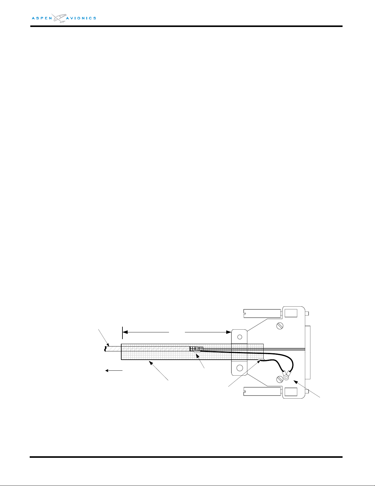
EFD1000 E5 Dual Electronic Flight Instrument (EFI) Install Manual
Solder then
Heat Shrink as required
M27500-22TG2V64 or equivalent
6 inches
To all ARINC 429 and
RS-232 Sources
Tinned Copper Over
Braid
Internal Ground
Lug
Solder Splice or Solder
both shields
7.2.4 HIRF/Lightning Requirements
In order to meet HIRF and Lightning requirements it is required that the following cable
runs use either an over braid applied during fabrication or double shielded wires. The
over braid or double shield must extend within the back shell and must be grounded at
both ends.
All ARINC 429 and RS-232 wiring into or out of the EFD require either a double-
shielded wire, or a tinned copper over braid be applied over the twisted shielded
pair. See NOTE 1 on Wiring Diagrams 9-4 through 9-14.
The following wires require single shields to comply with HIRF and Lightning
requirements:
Aircraft power to the EFD requires a single stranded shielded wire from circuit
breaker to EFD. See Figure 9-1.
EFD to Configuration Module comes as an assembly with color coded wires and
uses an over braid over non-shielded single conductor wires.
EFD1000 E5 to RSM wiring does not require the over braid or double shield, only what is
specified in Section 7.2.6.
ACU to GPS, ACU to VLOC receiver, and ACU to autopilot require no additional shielding
just what is specified in the wiring diagrams of Section 9.
7.2.5 EFD to GPS/VLOC/ACU Wiring
Use tinned copper over braid or double-shielded wires on all ARINC 429 and RS-232
wires entering or exiting the EFD back shell. Ground the over braid and wire shields
within the back shell. If using double shielded wire it may be difficult to terminate all
shields within the back shell. If this is the case then use a piece of tinned copper over
braid that extends at least 6 inches outside the back shell to cover all unshielded wires
(see Figure 7-1).
DOCUMENT # 900-00041-001 PAGE 81-226 REVISION D
Figure 7-1: EFD Back Shell Grounds
At the GPS/VLOC/ACU terminate the over braid within the back shell or as close as
possible. Ground the over braid at this end using a pigtail as short as possible. If using
© Copyright 2019 Aspen Avionics Inc.
Page 82

EFD1000 E5 Dual Electronic Flight Instrument (EFI) Install Manual
RSM Pin#
EFD Pin#
35ft Cable (412-00005-001)
50ft Cable (412-00006-001)
1
30
White/Black
Green/White
2
31
White/Red
Green
3
32
White/Orange
Brown
4
33
White/Yellow
Orange/White
5
34
White/Green
Orange
6
35
White/Blue
Blue, Blue/White
7
36
White
Brown/White
double shielded wires then ground both shields at the GPS/VLOC/ACU with pigtail as
short as possible.
7.2.6 RSM Wiring
The EFD1000 E5 to RSM wiring run is made with a single cable seven (7) conductor
shielded wire. M27500-A24SD7T23 or M27500-22TG7T14 seven (7) conductor shielded
cable can be used. Cable runs longer than 35ft are not recommended.
Ensure that a trap or drip loop is provided to prevent fluids or condensed moisture from
running into wires and cables dressed downward to a connector, terminal block, panel, or
junction box. See AC 43.13-1B Chapter 11.
7.2.6.1 Assembly using Aspen prefabricated 35ft and optional 50ft cables
This cable assembly is prefabricated with the following wire color markings and will be
cut to length at the EFD1000 E5.
7.2.6.2 Assembly using M27500-A24SD7T23 Cable
Terminate the aircraft side of the RSM wiring with the Hirose circular connector from
installation kit as shown in Figure 7-2 below. Due to the compact design of the Hirose
connector it may be easier to solder the wires to the solder cups on the bench versus
inside the tail of the aircraft. Use a fine tip soldering iron for this procedure.
1) Pass the cable through the hood and metal cover. Strip back the insulation to expose the
shielding and wires with the dimensions that are shown.
2) Stake the metal clamper to the shield in the location shown. A hexagonal crimper such as
the ones used for BNC Coax connector assembly work can be used to crimp it to
approximately 5.2mm outside diameter.
3) Assemble the two pieces of the connector such that the ring retains the solder cup piece.
Discard the washer as it is not required.
4) Solder the seven (7) 24 AWG wires to the connector.
5) Thread metal cover onto connector.
6) Insert screw into metal cover so that it indents into metal clamper.
7) Put hood over metal cover.
DOCUMENT # 900-00041-001 PAGE 82-226 REVISION D
© Copyright 2019 Aspen Avionics Inc.
Page 83
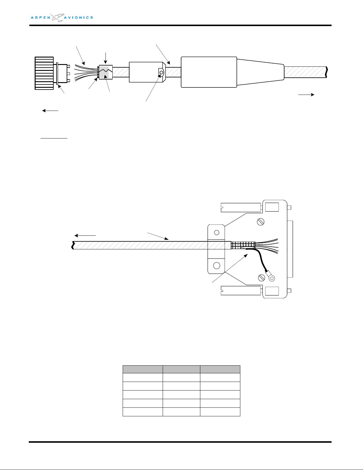
EFD1000 E5 Dual Electronic Flight Instrument (EFI) Install Manual
EFD Pin
Color
CM Pin
41
Black
1
42
Brown
2
43
Orange 4 44
Red
3
--
Green
5
Metal Clamper
Qty 7 – 22/24 AWG conductors
Screw
To
PFD
Hood
Metal
Cover
Connector
To
RSM
M27500-22TG7T14 or
M27500-A24SD7T23 or equivalent
Washer
Shield folded
back on jacket
Shield
Solder Splice or
solder then
Heat Shrink as required
To RSM
M27500-22TG7T14 or
M27500-A24SD7T23 or equivalent
Figure 7-2: RSM Connector assembly
CAUTION: Do not run RSM wiring near high current devices such as strobes and air conditioners and
avoid running RSM wiring in same wire bundle as strobe and air conditioning wiring
bundles if at all practical.
7.2.6.3
EFD END
Terminate the shield at the EFD end inside the back shell. Attach pigtail ground wire to
shield and connect to ground screw as shown in Figure 7-3.
Figure 7-3: EFD Back Shell Grounds/RSM
7.2.7 Configuration Module Wiring
The Configuration Module (CM) connector comes as an assembly with color-coded wires
within an over braid. The wires are inserted into the appropriate pins as shown in Figure
9-1. The green wire with ground lug is attached to back shell.
DOCUMENT # 900-00041-001 PAGE 83-226 REVISION D
Table 7-2: CM Wiring
© Copyright 2019 Aspen Avionics Inc.
Page 84

EFD1000 E5 Dual Electronic Flight Instrument (EFI) Install Manual
7.2.8 ACU Wiring
Wire the ACU as shown in Section 9 keeping all grounds as short as possible. No
additional HIRF shielding is required. The ACU case must be grounded to airframe
ground for proper operation.
7.2.9 Back Up NAV Indicator Wiring
Wire the NAV indicator as shown in Figures 9-24, 9-25, and 9-26. Do not parallel more
than one NAV Indicator to each ACU. When paralleling the wiring make the splice is as
close to the navigation receiver as practical. Do not splice the connection at the back of
the NAV indicator.
7.2.10 Autopilot Wiring
Wire the autopilot to ACU as shown in Section 9. Remove any existing connections and
switching between GPS and NAV receivers to autopilot. Only ARINC 429 wiring may
remain between the GPS and autopilot for NAV mode GPSS. The ACU will perform all
switching functions to autopilot for GPS1 and NAV1.
7.2.11 Backup Instrument Wiring and Cable bundle
Any existing wiring/cabling or tubing going to or coming from the backup turn and slip,
altimeter or the airspeed indicator must not route directly behind the rear of the EFD1000
E5 display head. Ensure it is secured away and below the display head fan assembly.
DOCUMENT # 900-00041-001 PAGE 84-226 REVISION D
© Copyright 2019 Aspen Avionics Inc.
Page 85

EFD1000 E5 Dual Electronic Flight Instrument (EFI) Install Manual
THIS PAGE IS INTENTIONALLY LEFT BLANK
DOCUMENT # 900-00041-001 PAGE 85-226 REVISION D
© Copyright 2019 Aspen Avionics Inc.
Page 86
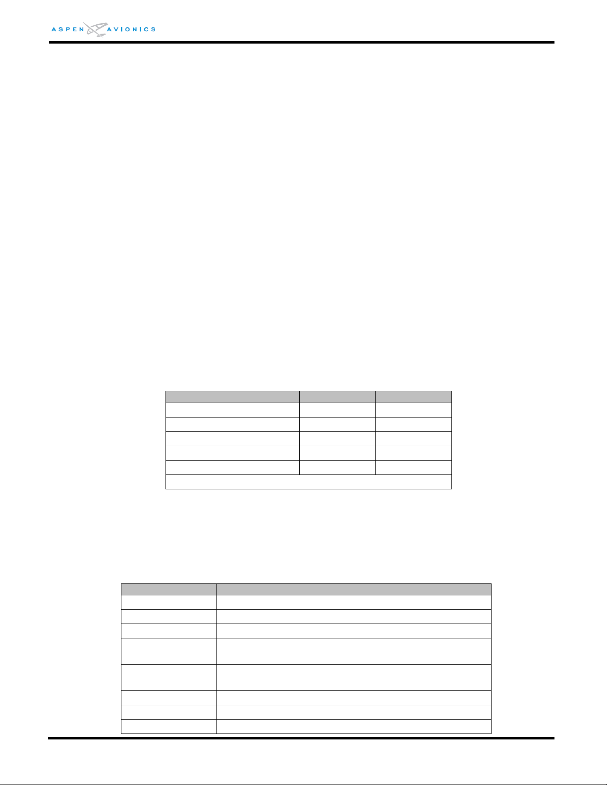
EFD1000 E5 Dual Electronic Flight Instrument (EFI) Install Manual
Label
ADC TYPE 1
ADC TYPE 2
Indicated Air Speed
X
X
Pressure Altitude
X
X
Rate of Turn
(1)
X
Vertical Speed
X
X
Heading Data
X
X
(1) This output is invalid when in “Degraded” mode
ARINC Label(s)
EFD Parameter
074
Data Record Header
075, bit 9 set
OBS/HOLD Mode
075, bit 9 not set
Auto Course Select
Label 100, bits 13(0)
and 12(1)
CDI Select (GPS) [GNAV installation only]
Label 100, bits 13(1)
and 12(0)
CDI Select (VLOC) [GNAV installation only]
Label 114
GPS “Desired Track”
Label 115
GPS “Waypoint Bearing”
Label 116
GPS “Crosstrack”
8 Electrical Connections
8.1 EFD Electrical Specifications
8.1.1 Power Input
Nominal Input: .................. 14Vdc or 28Vdc
Operating Range: .............. 9Vdc to 32Vdc (Note: Input power must transition >11VDC to
turn on the unit)
8.1.2 RS-232 GPS Input
Data is accepted in packets coded in the industry standard "avionics" format at a baud
rate of 9600, 8 data bits, 1 stop bit, no parity. Packets are accepted at approximately 1
Hz.
The following GPS configuration options are available in the Installation menu:
GPS TYPE 1 – KLN94 and KLN90B Standard RS-232 configuration.
GPS TYPE 2 – KLN94 Enhanced configuration. Allows the KLN94 to be configured for
Enhanced RS-232.
GPS TYPE 3 – GX-50/55/60/65 configuration.
8.1.3 RS-232 ADC Output
The EFD1000 E5 Display outputs the following computed air data output signals over the
RS-232 bus in Format Z (Shadin) (ADC TYPE 1) and Format C (Bendix King) (ADC TYPE 2):
8.1.4 ARINC 429 GPS Inputs
The EFD receives the following labels on pins (16, 17) and (20, 21) when transmitted
from a GPS receiver. ARINC 429 word definitions are implemented per GAMA Pub 11. The
GPS input ports can be configured either HIGH or LOW.
Table 8-1: RS-232 ADC Outputs
DOCUMENT # 900-00041-001 PAGE 86-226 REVISION D
© Copyright 2019 Aspen Avionics Inc.
Page 87
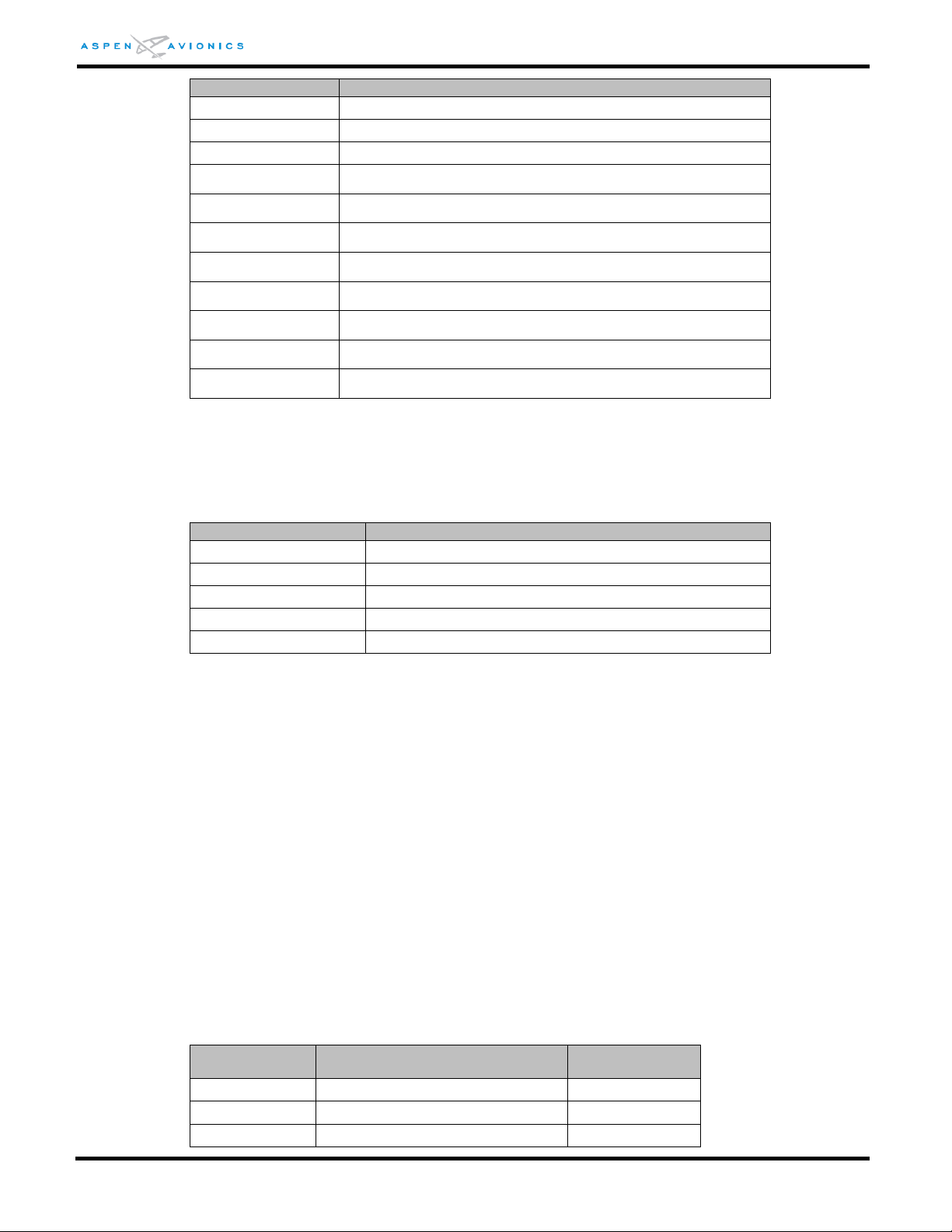
EFD1000 E5 Dual Electronic Flight Instrument (EFI) Install Manual
ARINC Label(s)
EFD Parameter
Label 117
GPS “Vertical Deviation”
Label 147
GPS “Magnetic Variation”
Label 121
GPS “Horizontal Command”
Label 251
GPS “Distance to Go”
Label 252
GPS “Time to Go”
Label 275, bit 23
GPS “TO” Flag
Label 275, bit 24
GPS “FROM” Flag
Label 312
GPS “Ground Speed”
Label 313
GPS “Track”
Label 326
GPS “Lateral Deviation Scale Factor” full precision
Label 327
GPS “Vertical Deviation Scale Factor” full precision
ARINC (Label)
EFD Parameter
Label 34
Tuned Frequency
Label 34, bit 14 set
ILS Energize
Label 173
Localizer deviation and validity flags
Label 174
Glide Slope deviation and validity flags
Label 222
VOR Omni bearing
ARINC Label
EFD Parameter
ARINC
Transmit Rate*
100
(1)
Selected Course
200ms
105
Heading Datum
50ms
173
Lateral Deviation
50ms
Table 8-2: EFD A429 GPS Input
8.1.5 ARINC 429 VLOC Input
The EFD receives the following labels on Pins (18, 19) and (22, 23) when transmitted from
a VLOC receiver. The VLOC input ports can be configured either HIGH or LOW.
8.1.6 ARINC 429 Output
The EFD1000 E5 transmits the following labels on pins 26 and 27 (Note – some labels are
only transmitted when configured for an ACU installation). Labels 350 and 354 are
proprietary ACU labels and should not be used for any purpose by any other third party
device.
Note – When connecting any third party device to this output it is the installer’s
responsibility to verify that the connected device does not have any adverse effects from
the labels below.
Note – The labels below are non-standard ARINC or GAMA labels due solely to the rate at
which the label is being transmitted.
Note- Except as shown in the wiring diagrams (Section 9) no ARINC 429 interface is
approved under the Aspen STC, and must be approved separately.
Table 8-3: EFD A429 VLOC Input
DOCUMENT # 900-00041-001 PAGE 87-226 REVISION D
© Copyright 2019 Aspen Avionics Inc.
Page 88

EFD1000 E5 Dual Electronic Flight Instrument (EFI) Install Manual
ARINC Label
EFD Parameter
ARINC
Transmit Rate*
174
Vertical Deviation
50ms
203
(1)
Pressure Altitude
200ms
204
(1)
Pressure Altitude (Baro corrected)
200ms
235
Baro Correction (inHg)
50ms
261G, bit 14
ILS Energize
50ms
261G, bit 15
GPS/NAV Select
50ms
261G, bit 16
Back Course
50ms
261G, bit 28
Altitude Engage
50ms
277
Course Datum
50ms
320
(1)
Magnetic Heading
50ms
350
ACU Config
1000m
354
ACU Config
1000ms
(1) These labels are the only ones transmitted when no ACU is configured.
*The label rate has a tolerance of +/- 15%
Table 8-4: EFD1000 E5 A429 GPS Output
8.2 ACU Electrical Specifications (910-00004 all dash numbers)
8.2.1 Power Input
Nominal Input: .................. 14Vdc or 28Vdc
Operating Range: .............. 11Vdc to 32Vdc
8.2.2 Reserved
8.2.3 VLOC Receiver
8.2.3.1 NAV Composite Input
An input connected to the composite output of a VHF Navigation receiver.
Nominal Input: .............. 0.5Vrms VOR
..................................... 0.35Vrms Localizer
Input Impedance: .......... 100K ohms
8.2.3.2 ILS Energize Discrete Input
Low impedance to ground supplied from a Navigation receiver when it is tuned to a
localizer frequency.
Active: ........................... Less than 500 ohms to ground or less than 1.5Vdc
Inactive: ........................ Open circuit sinking less than 1 ma to ground at 28Vdc
8.2.3.3 Glide Slope Deviation Input
A low level differential input that accepts a glide slope signal from an external VHF Nav
receiver.
Input Range: ................. ±150mVdc full scale
Max Input Range: .......... ±400mVdc
Load: ............................ 1000 ohm
DOCUMENT # 900-00041-001 PAGE 88-226 REVISION D
© Copyright 2019 Aspen Avionics Inc.
Page 89

EFD1000 E5 Dual Electronic Flight Instrument (EFI) Install Manual
8.2.3.4 Glide Slope Flag Input
A low level valid input from an external VHF Navigation receiver.
Valid: ............................ Greater than 260mV across a 1000-ohm load
Invalid: .......................... Less than 100mV across a 1000 ohm load
8.2.4 GPS Receiver
8.2.4.1 OBS Sine, Cosine, Rotor
An OBS resolver output for GPS receivers that require an OBS input. The resolver
output electrical zero is set to +60º (300º ORZ) for compatibility with most legacy
resolvers. The ACU accommodates OBS excitation with DC offset.
Excitation Amplitude: .... 5Vac min to 26Vac max (H to C)
Excitation Frequency: .... 30Hz to 5000Hz
Output Format: ............. Sine (D and E), Cosine (F and G)
Output Gradient: ........... Excitation * 0.401 (26Vac in = 10.4Vac out)
DC Offset: ..................... 0Vdc to +5Vdc (Offset applied to Rotor C)
8.2.4.2 TO/ FROM FLAG Input
Differential input from a GPS receiver indicating whether flying TO or FROM the active
waypoint.
TO the waypoint: ........... +40mV or greater
FROM the waypoint: ...... -40mV or greater
8.2.4.3 LEFT/ RIGHT Input
Differential input from a GPS receiver indicating LEFT or RIGHT of GPS course.
Input Range: ................. ±150mVdc full scale
Load: ............................ 1000 ohm
8.2.4.4 Lateral Flag Input
Validity flag from the GPS receiver indicating valid LEFT and RIGHT data.
Valid: ............................ 260mV to 800mVdc
Invalid: .......................... Less than 260mVdc
8.2.4.5 Vertical Deviation Input
Differential input from a GPS receiver indicating a fly UP or DOWN command.
Input Range: ................. ±150mVdc full scale
Load: ............................ 1000 ohm
8.2.4.6 Vertical Deviation Flag Input
Validity flag from the GPS receiver indicating valid UP and DOWN data.
Valid: ............................ 260mV to 800mVdc
Invalid: .......................... Less than 260mVdc
8.2.4.7 OBS/ LEG (HOLD) Input
Active low discrete input from a GPS receiver when in the OBS or HOLD mode.
DOCUMENT # 900-00041-001 PAGE 89-226 REVISION D
© Copyright 2019 Aspen Avionics Inc.
Page 90

EFD1000 E5 Dual Electronic Flight Instrument (EFI) Install Manual
8.2.4.8 APPR Active Input
Active low discrete input from a GPS receiver when approach mode is activated.
8.2.4.9 FCS-LOC Engage Input
Active low discrete input from a GPS receiver when approach is selected.
8.2.5 Autopilot
8.2.5.1 Lateral Deviation Output
A low-level lateral deviation output that is connected to an autopilot lateral deviation
(RT/LT) input. The low side of the differential output is referenced to ground. Before
connecting this output verify the receiving equipment’s left/right input can
accommodate a ground potential on the low side.
Lateral Deviation: .......... ±150mVdc minimum for full scale CDI deflection
Sense: ........................... Positive voltage for fly right
Load: ............................ Will drive up to three 1000 ohm loads
8.2.5.2 Lateral Flag Output
A low level valid output to the autopilot indicating the Lateral (LT/RT) signal from the
ACU is valid.
Valid: ............................ 0.4 to 0.8Vdc
Invalid: .......................... Less than 0.05Vdc
Load: ............................ Will drive up to three 1000 ohm loads
NOTE – ACU2 P/N 910-00004-102 does not have a low level flag. It provides a discrete to ground
for energizing an external superflag relay.
8.2.5.3 Vertical Deviation Output
A low level vertical deviation output that is connected to an autopilot vertical (UP/DN)
input. The low side of the differential output is referenced to ground.
Output Voltage: ............. ±150mVdc nominal, tracks the glide slope deviation input
signal to within 5%
Loading: ........................ Up to three 1000-ohm loads
8.2.5.4 Vertical Flag Output
A low level output to the autopilot indicating the UP/DN from the ACU is valid.
Valid: ............................ 0.4 to 0.8Vdc
Invalid: .......................... Less than 0.05Vdc
Load: ............................ Will drive up to three 1000-ohm loads
NOTE – ACU2 P/N 910-00004-102 does not have a low level flag. It provides a discrete to ground
for energizing an external superflag relay.
8.2.5.5 ILS Energize Output
Active low output to an autopilot when an ILS is selected or GPS approach is active.
ILS/GPS APPR Active: ..... Sink to ground
ILS/GPS APPR Inactive: ... Open
Load Current: ................ 100ma maximum
DOCUMENT # 900-00041-001 PAGE 90-226 REVISION D
© Copyright 2019 Aspen Avionics Inc.
Page 91

EFD1000 E5 Dual Electronic Flight Instrument (EFI) Install Manual
BENDIX KING KI525A EMULATION
ACU HSI TYPE = 0
1
DATUM
SCALING
2
REFERENCE
VOLTAGE
ACU P3-23
DESCRIPTION
(with ACU DATUM = NORMAL)
HDG
ACU P3-22
500mVdc
per degree
up to a
maximum
angle of 30⁰,
or 15Vdc.
15Vdc
500mVdc per degree up to a maximum angle of
30⁰, or 15Vdc. The output remains at +15Vdc from
31⁰ to 180⁰. At 181⁰ it switches to -15Vdc.
Likewise for negative angles (HDG bug left of the
lubber line) the gradient is -500mVdc per degree
up to -30⁰. The output remains at -15Vdc from
-31⁰ to -179⁰. At 180⁰ it switches to +15Vdc.
CRS
ACU P3-3
167mVdc
per degree
up to 90⁰, or
15Vdc.
15Vdc
167mVdc per degree up to 90⁰, or +15Vdc. From
91⁰ to 180⁰ the output diminishes by 167mVdc per
degree, reaching 0Vdc at 180⁰. For negative angles
(CRS pointer left of the lubber line) the gradient is
-167mVdc per degree up to -90⁰. From -90⁰ to
-179⁰ the output diminishes by 167mVdc per
degree reaching 0Vdc at 180⁰.
1
Datum outputs are in reference to ACU P3-11, ACU reference ground.
2
15Vdc reference may come from ACU P3-9, ACU +15Vdc Out.
NSD-360 EMULATION
ACU HSI TYPE = 1
1
DATUM
SCALING
2
REFERENCE
VOLTAGE
ACU P3-23
DESCRIPTION
(with ACU DATUM = NORMAL)
HDG
ACU P3-22
167mVdc per
degree up to
90⁰, or
15Vdc.
15Vdc
Reference
voltage may
be any
positive DC
or AC
reference
voltage
Assuming a reference voltage of 15Vdc, the
gradient is 167mVdc per degree up to 90⁰, or
+15Vdc. From 91⁰ to 180⁰ the output diminishes
by 167mVdc per degree, reaching 0Vdc at 180⁰.
For negative angles (HDG Bug left of the lubber
line) the gradient is -167mVdc per degree up to
-90⁰. From -90⁰ to -179⁰ the output diminishes by
167mVdc per degree reaching 0Vdc at 180⁰.
8.2.5.6 Volt Reference Output
An internally generated +15Vdc reference for KI-525 emulation.
Output Voltage: ............. +15Vdc ±2Vdc
Load Current: ................ 30ma maximum
8.2.5.7 KI-525A Heading and Course Datum Output
Emulated KI-525A outputs to drive the heading and course datum inputs of an
autopilot.
Table 8-5: KI525A Emulation Specifications
8.2.5.8 NSD-360 Heading and Course Datum Output
Emulated NSD-360 outputs to drive the heading and course datum inputs of an
autopilot.
DOCUMENT # 900-00041-001 PAGE 91-226 REVISION D
© Copyright 2019 Aspen Avionics Inc.
Page 92

EFD1000 E5 Dual Electronic Flight Instrument (EFI) Install Manual
CRS
ACU P3-3
167mVdc per
degree up to
90⁰, or
15Vdc.
15Vdc
Reference
voltage may
be any
positive DC
or AC
reference
voltage
Assuming a reference voltage of +15Vdc, the
gradient is 167mVdc per degree up to 90⁰, or
+15Vdc. From 91⁰ to 180⁰ the output diminishes
by 167mVdc per degree, reaching 0Vdc at 180⁰.
For negative angles (CRS pointer left of the lubber
line) the gradient is -167mVdc per degree up to
-90⁰. From -90⁰ to -179⁰ the output diminishes by
167mVdc per degree reaching 0Vdc at 180⁰.
1
Datum outputs are in reference to ACU P3-11, ACU reference ground.
2
Reference voltage typically comes from autopilot computer.
PN-101 EMULATION
ACU HSI TYPE = 3
1
DATUM
SCALING
2
REFERENCE
VOLTAGE
ACU P3-21
DESCRIPTION
(with ACU DATUM = NORMAL)
HDG
ACU P3-22
The gradient is
scaled to
11.8Vac
maximum at
90⁰ when using
a 26Vac
reference. It is
linear between
0⁰ and 90⁰.
26Vac
Reference
voltage may
be any AC
reference
voltage
Assuming a reference voltage of 26Vac, the
gradient is 131mVac per degree up to 90⁰, or
11.8Vac. From 91⁰ to 180⁰ the output
diminishes by 131mVac per degree, reaching
0Vac at 180⁰. For negative angles (HDG Bug left
of the lubber line) the gradient is out of phase
with the reference and is 131mVac per degree
up to -90⁰. From -90⁰ to -179⁰ the output
diminishes by 131mVac per degree reaching
0Vdc at 180⁰.
CRS
ACU P3-3
The gradient is
scaled to
11.8Vac
maximum at
90⁰ when using
a 26Vac
reference. It is
linear between
0⁰ and 90⁰.
26Vac
Reference
voltage may
be any AC
reference
voltage
Assuming a reference voltage of 26Vac, the
gradient is 131mVac per degree up to 90⁰, or
11.8Vac. From 91⁰ to 180⁰ the output
diminishes by 131mVac per degree, reaching
0Vac at 180⁰. For negative angles (HDG Bug left
of the lubber line) the gradient is out of phase
with the reference and is 131mVac per degree
up to -90⁰. From -90⁰ to -179⁰ the output
diminishes by 131mVac per degree reaching
0Vdc at 180⁰.
1
Datum outputs are in reference to ACU P3-11, ACU reference ground.
2
Reference voltage typically comes from autopilot computer or aircraft inverter.
Table 8-6: NSD360A Emulation Specifications
8.2.5.9 PN-101 Heading and Course Datum Output
Emulated PN-101 outputs to drive the heading and course datum inputs of an autopilot.
Table 8-7: PN101 Emulation Specifications
8.2.5.10 Heading Valid Output
Active low discrete output indicating the EFD directional gyro is valid.
Valid: ............................ Sinks to ground
DOCUMENT # 900-00041-001 PAGE 92-226 REVISION D
Invalid: .......................... Open
Load Current: ................ 100ma maximum
© Copyright 2019 Aspen Avionics Inc.
Page 93

EFD1000 E5 Dual Electronic Flight Instrument (EFI) Install Manual
ARINC
Label
EFD Data
Rate
(ms)
100
Selected Course
200
320
Magnetic Heading
200
8.2.5.11 GPS Selected Output
Active low discrete output indicating GPS1 or GPS2 is the current coupled sensor on the
HSI.
GPS coupled: ................. Sinks to ground
GPS not coupled: ........... Open
Load Current: ................ 100ma maximum
8.2.5.12 ARINC 429 Output
The ACU transmits the following labels on P3 pins 4 and 5 for GPS receivers and
systems that require ARINC 429 magnetic heading and selected course.
Note- Except as shown in the wiring diagrams (Section 9) no ARINC 429 interface is
approved under the Aspen STC, and must be approved separately.
Table 8-8: ACU A429 Output
8.3 ACU2 Electrical Specifications (910-00004-10x only)
The ACU2 has the same interfaces as the ACU above on connectors J1/J2/J3 plus it adds the
following interfaces on connector J4.
8.3.1 Heading Synchro Out
The ACU2 will output a heading synchro (bootstrap) signal per ARINC 407 to external
equipment.
Heading Reference In:
Input Range: ...................... 17Vac to 30Vac
Frequency Range: .............. 300Hz to 5500Hz
Load: ................................. at least 68100 ohm
Heading Reference Out:
Output Voltage: ................. 17Vac to 30Vac (26Vrms nominal) into a 10000 ohm load
Frequency Range: .............. 350Hz to 450Hz
Load: ................................. 10000 ohm
Synchro Output:
Output Format: .................. V
Output Range: ................... 0 to 11.8Vrms
The ACU2 will disable the heading reference output when an external reference of greater
than 18Vac is applied across pins 26V-REF-H and 26V-REF-C.
= V
X-z
V
Y-Z
sin(Ө - 120⁰)
Ref
= V
sin(Ө + 120⁰)
Ref
DOCUMENT # 900-00041-001 PAGE 93-226 REVISION D
Heading Valid:
Open Collector output to the heading valid flag. It can sink up to 100mA to ground at
28Vdc.
© Copyright 2019 Aspen Avionics Inc.
Page 94
EFD1000 E5 Dual Electronic Flight Instrument (EFI) Install Manual
ARINC
Label
EFD Data
Rate (ms)
100
Selected Course
200
320
Magnetic Heading
200
203
Pressure Altitude
200
204
Baro Corrected Altitude
200
Pin
Number
Name
Input /
Output
Function
1
POWER
-
Main DC power input
2
POWER
- “ 3
POWER
- “ 4
GND
-
Main DC ground
5
GND
- “ 6
GND
- “ 7
Digital Discrete
OUTPUT
n/a
8
RS-232RX1
INPUT
RS-232 RX1 (115kb)
9
RS-232RX2
INPUT
RS-232 RX2
10
RS-232RX3
INPUT
RS-232 RX3
11
RS-232RX4
INPUT
RS-232 RX4
12
RS-232RX5
INPUT
RS-232 RX5
13
RS-232TX1
OUTPUT
RS-232 TX1
14
RS-232TX2
OUTPUT
RS-232 TX2
15
RS-232TX3
OUTPUT
RS-232 TX3
16
ARINCRX1A
INPUT
ARINC Receiver 1
17
ARINCRX1B
INPUT
ARINC Receiver 1
18
ARINCRX2A
INPUT
ARINC Receiver 2
19
ARINCRX2B
INPUT
ARINC Receiver 2
8.3.2 +/- 15Vdc Power Output
The ACU2 outputs +15Vdc and -15Vdc to external equipment such as a Bendix King KA52/57.
+15 Range: ....................... +14Vdc to +15.5Vdc at up to 150mA
-15 Range: ........................ -14Vdc to -15.5Vdc at up to 150mA
8.3.3 Glideslope Flag (Narco)
The ACU2 provides a high impedance (10K) glideslope flag input for use with Narco and
other NAV radios unable to drive the standard 1k load.
Valid: ................................ Greater than 260mV across a 10000-ohm load
Invalid: .............................. Less than 100mV across a 10000 ohm load
8.3.4 ARINC 429 Output
The ACU2 transmits the following labels on J3-4/J3-5 (TX2) for GPS receivers and systems
that require ARINC 429 magnetic heading, air data and selected course. Can be
configured High or Low speed.
Note- Except as shown in the wiring diagrams (Section 9) no ARINC 429 interface is
approved under the Aspen STC, and must be approved separately.
8.4 EFD Pin Out
Table 8-9: ACU2 ARINC 429 Output
DOCUMENT # 900-00041-001 PAGE 94-226 REVISION D
© Copyright 2019 Aspen Avionics Inc.
Page 95
EFD1000 E5 Dual Electronic Flight Instrument (EFI) Install Manual
Pin
Number
Name
Input /
Output
Function
20
ARINCRX3A
INPUT
ARINC Receiver 3
21
ARINCRX3B
INPUT
ARINC Receiver 3
22
ARINCRX4A
INPUT
ARINC Receiver 4
23
ARINCRX4B
INPUT
ARINC Receiver 4
24
ARINCRX5A
INPUT
ARINC Receiver 5
25
ARINCRX5B
INPUT
ARINC Receiver 5
26
ARINCTX1A
OUTPUT
ARINC Transmitter 1
27
ARINCTX1B
OUTPUT
ARINC Transmitter 1
28
Reserved
-
Future Expansion
29
Reserved
- “ 30
RS-232TX0
OUTPUT
RS-232 TX
31
RS-232RX0
INPUT
RS-232 RX0 (115kb)
32
RSMC
-
RSM data
33
RSMD
-
RSM data
34
RSME
-
RSM data
35
RSMF
-
RSM data
36
RSMG
-
RSM data
37
ENET TX+
OUTPUT
Ethernet TX bus
38
ENET TX-
OUTPUT
Ethernet TX bus
39
ENET RX+
INPUT
Ethernet RX bus
40
ENET RX-
INPUT
Ethernet RX bus
41
CONFIGA
-
Configuration Module connection
42
CONFIGB
- “ 43
CONFIGC
- “ 44
CONFIGD
-
“
44
15
31
1
16
30
Table 8-10: EFD Pin Out
Figure 8-1: EFD Connector (as viewed from rear of unit)
DOCUMENT # 900-00041-001 PAGE 95-226 REVISION D
© Copyright 2019 Aspen Avionics Inc.
Page 96
EFD1000 E5 Dual Electronic Flight Instrument (EFI) Install Manual
Pin
Number
Name
Input /
Output
Function
1
RSMA
-
RSM Connection
2
RSMB
-
RSM Connection
3
RSMC
-
RSM Connection
4
RSMD
-
RSM Connection
5
RSME
-
RSM Connection
6
RSMF
-
RSM Connection
7
RSMG
-
RSM Connection
Pin
Number
Name
Input /
Output
Function
1
ConfigA
-
CM Connection
2
ConfigB
-
CM Connection
3
ConfigD
-
CM Connection
4
ConfigC
-
CM Connection
5
ConfigS
-
Shield Ground
7
6
5
4
3
1
2
7
1
2
3
4
6
5
2
1
3
5
4
8.5 RSM Pin Out
Table 8-11: RSM Pin Out
Male Pin Side Solder Cup Side
Figure 8-2: RSM Mating Connector –Install Side
8.6 Configuration Module Pin Out
Table 8-12: Configuration Module Pin Out
DOCUMENT # 900-00041-001 PAGE 96-226 REVISION D
Figure 8-3: Configuration Module Connector (Install side)
© Copyright 2019 Aspen Avionics Inc.
Page 97
EFD1000 E5 Dual Electronic Flight Instrument (EFI) Install Manual
Pin
Number
Name
Input /
Output
Function
J1-1
429RX2A
INPUT
ARINC 429 Port 2 Receive A
J1-2
429RX2B
INPUT
ARINC 429 Port 2 Receive B
J1-3
PWR-COM
-
Power Common
J1-4
GPS+LT
INPUT
GPS Lateral Dev Input (-)
J1-5
GPS-LATFLG
INPUT
GPS Lateral Flag Input (-)
J1-6
GPS+DN
INPUT
GPS Vertical Dev Input (-)
J1-7
GPS+FR
INPUT
GPS TO/FROM Input
J1-8
GPS-VERTFLG
INPUT
GPS Vertical Dev Flag (-)
J1-9
Reserved
-
Reserved
J1-10
+11 to 32Vdc
-
Aircraft Primary Power
J1-11
GPS+RT
INPUT
GPS Lateral Dev Input (+)
J1-12
GPS+LATFLG
INPUT
GPS Lateral Flag Input (+)
J1-13
GPS+UP
INPUT
GPS Vertical Dev Input (+)
J1-14
GPS+TO
INPUT
GPS TO/FROM Input
J1-15
GPS+VERTFLG
INPUT
GPS Vertical Flag (+)
Pin
Number
Name
Input /
Output
Function
J2-1
COMPOSITE
INPUT
VOR/LOC Composite input
J2-2
/ILS-ENERGIZE
INPUT
Active Low input from VHF Nav Rx
J2-3
/Spare-Disc1
INPUT
Spare Discrete Input
J2-4
1
/BACK-CRSOUT
OUTPUT
Open collector output to drive the back course
sense circuit of an autopilot
J2-5
/ILS-ENERGIZEOUT
OUTPUT
Active Low Output when ILS Selected or GPS Appr
Active
J2-6
/FCS-LOC-IN
INPUT
Low Input from GPS when Appr Selected
J2-7
/OBS-LEG-IN
INPUT
Active Low from GPS when GPS OBS mode selected
J2-8
-DH
INPUT
N/A
J2-9
FD-ENGAGED
INPUT
N/A
J2-10
FD-ROLL2
INPUT
N/A
J2-11
+VLOCFLG-OUT
OUTPUT
Valid VHF Nav VOR or Localizer signal
J2-12
+GS-IN
INPUT
Glideslope deviation from VHF Nav Rx
1
9
15
8
8.7 ACU/ACU2 Pin Out
Table 8-13: ACU J1 Pin Out
Figure 8-4: ACU J1 Connector (as viewed from front of unit)
DOCUMENT # 900-00041-001 PAGE 97-226 REVISION D
© Copyright 2019 Aspen Avionics Inc.
Page 98
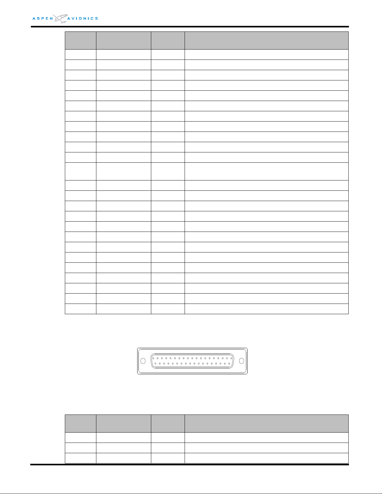
EFD1000 E5 Dual Electronic Flight Instrument (EFI) Install Manual
Pin
Number
Name
Input /
Output
Function
J2-13
+GSFLG-IN
INPUT
Glideslope flag from VHF Nav Rx
J2-14
FD-PITCH-COM
INPUT
N/A
J2-15
FD-ROLL-COM
INPUT
N/A
J2-16
+UP
OUTPUT
Vertical output to autopilot (H)
J2-17
+VERT-FLG
OUTPUT
Vertical output flag (H)
J2-18
+RT
OUTPUT
Lateral deviation output
J2-19
ACU #1/#2
INPUT
Spare Discrete Input
J2-20
COMPOSITE-COM
-
VOR/LOC common
J2-21
Reserved
-
Spare Discrete Input
J2-22
Reserved
-
Spare Discrete Input
J2-23
Reserved
-
Reserved
J2-24
APPR-ACT
INPUT
Active Low input from GPS when GPS approach
mode activated
J2-25
1
HEADING VALID
OUTPUT
Active Low Output when Heading Valid
J2-26
+DH
INPUT
N/A
J2-27
FD-VALID
INPUT
N/A
J2-28
FD-PITCH2
INPUT
N/A
J2-29
ALT ENGAGE
OUTPUT
N/A
J2-30
-VLOCFLG-OUT
-
Common
J2-31
-GS-IN
INPUT
Glideslope deviation from VHF Nav Rx
J2-32
-GSFLG-IN
INPUT
Glideslope flag from VHF Nav Rx
J2-33
FD-PITCH1
INPUT
N/A
J2-34
FD-ROLL1
INPUT
N/A
J2-35
+DN
OUTPUT
Vertical output to autopilot (L)
J2-36
-VERT-FLG
OUTPUT
Vertical output flag (L)
J2-37
+LT
OUTPUT
Lateral deviation output
Pin
Number
Name
Input /
Output
Function
J3-1
429RX1A
INPUT
ARINC 429 Port 1 Receive A
J3-2
429TX1A
OUTPUT
ARINC 429 Port 1 Transmit A
J3-3
CRS-DATUM
OUTPUT
Course Datum output
20
1
37
19
1
NOTE – On ACU2 P/N 910-00004-102, J2-4 is a NAV Flag Discrete and J2-25 is a Glide
Slope Flag Discrete used on autopilots that require a superflag input.
Figure 8-5: ACU J2 Connector (as viewed from front of unit)
DOCUMENT # 900-00041-001 PAGE 98-226 REVISION D
Table 8-14: ACU J2 Pin Out
© Copyright 2019 Aspen Avionics Inc.
Page 99
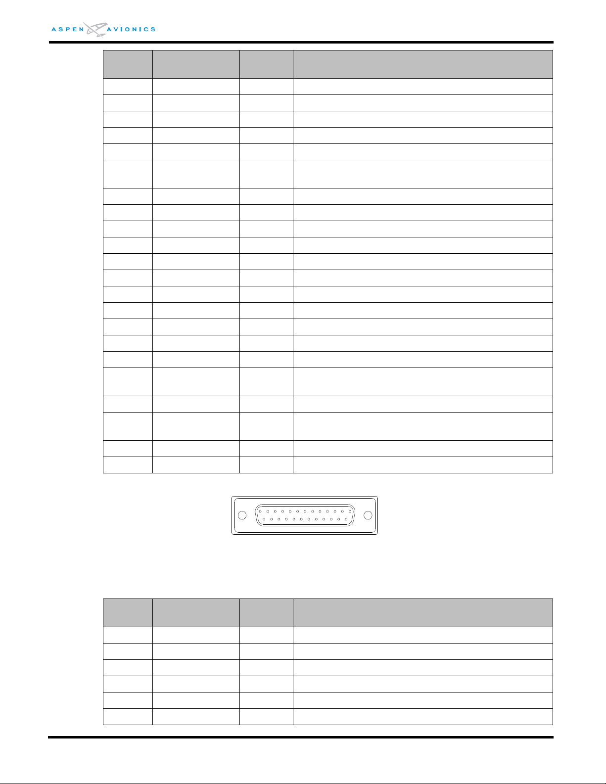
EFD1000 E5 Dual Electronic Flight Instrument (EFI) Install Manual
Pin
Number
Name
Input /
Output
Function
J3-4
429TX2A
OUTPUT
ARINC 429 Port 2 Transmit A
J3-5
429TX2B
OUTPUT
ARINC 429 Port 2 Transmit B
J3-6
OBS SIN -
OUTPUT
Sin of selected course angle (L)
J3-7
OBS COS -
OUTPUT
Cos of selected course angle (L)
J3-8
ROTOR C
OUTPUT
OBS sin/cos excitation (L)
J3-9
+15V-EXTOUT
OUTPUT
Internal +15Vdc reference
J3-10
SIGNAL-COM
-
Signal ground
J3-11
HDG/CRS-COM
-
Signal ground
J3-12
Reserved
-
Reserved
J3-13
Reserved
-
Reserved
J3-14
429RX1B
INPUT
ARINC 429 Port 1 Receive B
J3-15
429TX1B
OUTPUT
ARINC 429 Port 1 Transmit B
J3-16
SIGNAL-COM
-
Signal ground
J3-17
GPS SELECTED
OUTPUT
Active Low signal to drive GPS and Autopilot inputs.
J3-18
OBS SIN +
OUTPUT
Sin of selected course angle (H)
J3-19
OBS COS +
OUTPUT
Cos of selected course angle(H)
J3-20
ROTOR H
INPUT
OBS sin/cos excitation (H)
J3-21
ARINC-HDGCRS-EXT
-
26Vac reference to emulate an ARINC synchro
interface
J3-22
HDG-DATUM
OUTPUT
Heading Datum output
J3-23
HDG-CRSDATUM-EXT
INPUT
Heading/Course Datum excitation input
J3-24
Reserved
-
Reserved
J3-25
HDG-CRS-OFST
INPUT
Heading/Course Datum excitation offset input
Pin
Number
Name
Input /
Output
Function
J4-1
+15VDC Out
OUTPUT
15Vdc power to external equipment
J4-2
429TX3B
OUTPUT
ARINC 429 Port 3 Transmit B
J4-3
429RX3B
INPUT
ARINC 429 Port 3 Receive B
J4-4
400HZ-REF-LO
OUTPUT
400Hz excitation for heading synchro
J4-5
HDG Y
OUTPUT
Heading synchro (Y-Z)
J4-6
DME1-DATA +8V
INPUT
N/A
1
14
13
25
Figure 8-6: ACU J3 Connector (as viewed from front of unit)
DOCUMENT # 900-00041-001 PAGE 99-226 REVISION D
© Copyright 2019 Aspen Avionics Inc.
Table 8-15: ACU J3 Pin Out
Page 100

EFD1000 E5 Dual Electronic Flight Instrument (EFI) Install Manual
Pin
Number
Name
Input /
Output
Function
J4-7
DME1-CLK +8V
INPUT
N/A
J4-8
DME2-GATE +8V
INPUT
N/A
J4-9
DME-COM
INPUT
N/A
J4-10
ADF1 +REF
INPUT
N/A
J4-11
OAT +5
OUTPUT
N/A
J4-12
ADF2 +REF
INPUT
N/A
J4-13
OATSIG
INPUT
N/A
J4-14
422TX1+
OUTPUT
RS-422 Port 1 Serial Data Out
J4-15
422TX2+
OUTPUT
RS-422 Port 2 Serial Data Out
J4-16
422RX1B
INPUT
RS-422 Port 1 Serial Data In, or RS-232 RX1
J4-17
422RX2A
INPUT
RS-422 Port 2 Serial Data In
J4-18
/DISC1
OUTPUT
N/A
J4-19
/DISC3
OUTPUT
Active Low Discrete Output
J4-20
+RADALT
INPUT
N/A
J4-21
RADALT-VLD
INPUT
N/A
J4-22
-15VDC OUT
OUTPUT
-15Vdc Output for external equipment
J4-23
429TX3A
OUTPUT
ARINC 429 Port 3 Transmit A
J4-24
429RX3A
INPUT
ARINC 429 Port 3 Receive A
J4-25
400HZ-REF-HI
OUTPUT
400Hz excitation for heading synchro
J4-26
HDG-X
OUTPUT
Heading synchro output (X-Z)
J4-27
HDG-Z
OUTPUT
Heading synchro output (Z)
J4-28
DME1-GATE +8V
INPUT
N/A
J4-29
DME2-DATA +8V
INPUT
N/A
J4-30
DME2-CLK +8V
INPUT
N/A
J4-31
ADF1+SIN
INPUT
N/A
J4-32
ADF1+COS
INPUT
N/A
J4-33
ADF2+SIN
INPUT
N/A
J4-34
ADF2+COS
INPUT
N/A
J4-35
422TX1-
OUTPUT
RS-422 Port 1 Serial Data Out, or RS-232 TX1
J4-36
422TX2-
OUTPUT
RS-422 Port 2 Serial Data Out, or RS-232 TX2
J4-37
422RX1A
INPUT
RS-422 Port 1 Serial Data In
J4-38
232/422
SERIAL COM
-
Chassis Ground
J4-39*
422RX2B
INPUT
RS-422 Port 2 Serial Data In, or RS-232 RX2
J4-40
/DISC2
OUTPUT
N/A
J4-41
/DISC4
OUTPUT
Active Low Discrete Output
J4-42
-RADALT
INPUT
N/A
J4-43
ANN-LOAD
INPUT
N/A
J4-44
/SPARE-DISC3
INPUT
Discrete Input
J4-45
/SPARE-DISC4
INPUT
Discrete Input
DOCUMENT # 900-00041-001 PAGE 100-226 REVISION D
© Copyright 2019 Aspen Avionics Inc.
 Loading...