

Page 1
ASKO
INSTALLATION
INSTRUCTIONS
IMPORTANT!
Read all of these instructions
before installing the dishwasher .
AA
UTUT
OMAOMA
A
UT
OMA
AA
UTUT
OMAOMA
TT
he drhe dr
T
he dr
TT
he drhe dr
back of the machine at the bestback of the machine at the best
back of the machine at the best
back of the machine at the bestback of the machine at the best
high loop height.high loop height.
high loop height.
high loop height.high loop height.
potential drpotential dr
potential dr
potential drpotential dr
this hose in place.this hose in place.
this hose in place.
this hose in place.this hose in place.
TIC HIGH LTIC HIGH L
TIC HIGH L
TIC HIGH LTIC HIGH L
ain hose is fain hose is f
ain hose is f
ain hose is fain hose is f
TT
T
TT
ain prain pr
ain pr
ain prain pr
obob
ob
obob
OOPOOP
OOP
OOPOOP
astened to theastened to the
astened to the
astened to theastened to the
o eliminao elimina
o elimina
o eliminao elimina
lemslems
lems
lemslems
,,
lea lea
,
lea
,,
lea lea
tete
te
tete
vv
ee
v
e
vv
ee
DISHWASHER
CONTENTSCONTENTS
CONTENTS
CONTENTSCONTENTS
Introduction 2
What You Need 2
Dimensions 3
Preparing the Location 3
Hot Water Supply 4
Drain Supply 5
Electrical Connections 6
Preparing the Dishwasher for Installation 6
Moving the Machine into Place 7
Connecting the Electric Cable 7
Connecting the Water Supply 8
Adjusting the Leveling Legs 8
Fastening the Dishwasher to the Cabinet 8
Replacing the Toe Kick Brackets 9
Installing the T oe Kick 9
Changing the Front Panels 9
Fitting the 1805FI Custom Door Panel 10
Fitting the Semi-integrated Custom Door Panel on Model 1895 12
SAVE THESE INSTRUCTIONS FOR FUTURE REFERENCE
Page 1
Page 2
INTRODUCTIONINTRODUCTION
INTRODUCTION
INTRODUCTIONINTRODUCTION
Read these instructions carefully and completely before
you install the machine. The installation should be
carried out by a qualified person who is familiar with all
local codes and ordinances for electrical and plumbing
connections.
If a dishwasher is being installed in this area for the
first time, most of the cabinet work, plumbing, and
electrical has to be done before you move the machine
into place.
WHAWHA
WHA
WHAWHA
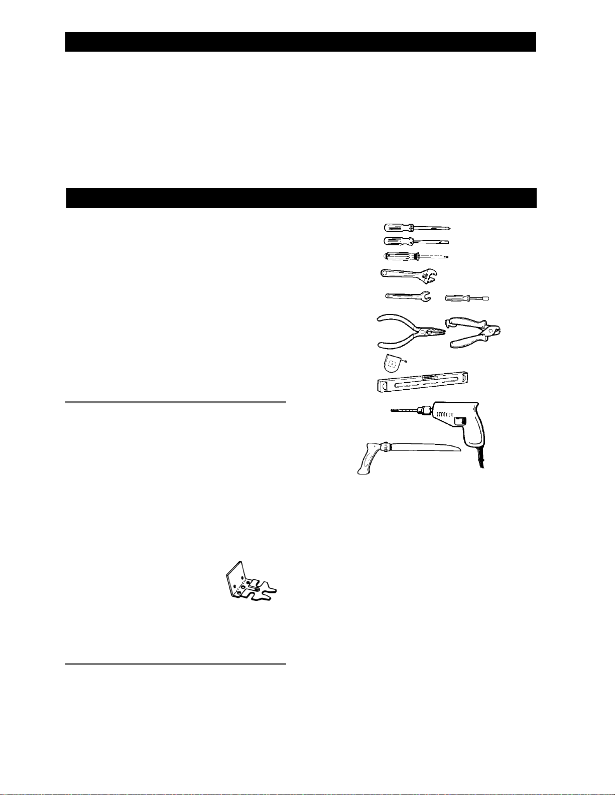
TOOLSTOOLS
TOOLS
TOOLSTOOLS
1) Phillips No. 2 screwdriver
2) Flat blade screwdriver
3) Torx screwdriver size T 20
4) Adjustable wrenches (if you use copper fittings)
5) Open-ended wrench (1/2" [12 mm] or 5/8" [16 mm])
6) Wire cutters and strippers
7) Tape measure
8) Spirit level
9) Electric drill with 1” drill bit
10) Keyhole saw
T T
YY
OU NEEDOU NEED
T
Y
OU NEED
T T
YY
OU NEEDOU NEED
If you are replacing an old dishwasher, you must check
the plumbing connection and wiring before you move
the new dishwasher into place.
NOTE:
ASKO dealer within five days from the date of purchase.
After unpacking the dishwasher, thoroughly check the
unit for cosmetic damage.
Cosmetic damage must be reported to the
1)
2)
3)
4)
5)
6)
7)
8)
MAMA
TERIALSTERIALS
MA
TERIALS
MAMA
TERIALSTERIALS
♦ Minimum 3/8" OD copper tubing of sufficient length
for your installation
♦ Shut-off valve and fittings for water supply line
♦ 1 compression nut
♦ 1 compression sleeve
♦ 1 90° street elbow
♦ 1 90° compression elbow, 3/8" (10 mm) OD
Tip Guards (optional)Tip Guards (optional)
Tip Guards (optional)
Tip Guards (optional)Tip Guards (optional)
When it is not possible to attach the
dishwasher to the cabinet, you
should install tip guards to prevent
the machine from tipping when you
open the door.
Refer to page 3 for installation
instructions.
TECHNICAL DTECHNICAL D
TECHNICAL D
TECHNICAL DTECHNICAL D
Water pressure 18-176 psi
Power 120 v, 60 Hz, 15 amp.
Heating element 1400 w
Max loading 1650 w
AA
A
AA
TT
T
TT
AA
A
AA
Tip Guards
(P/N 8070851)
9)
10)
Page 2
Page 3
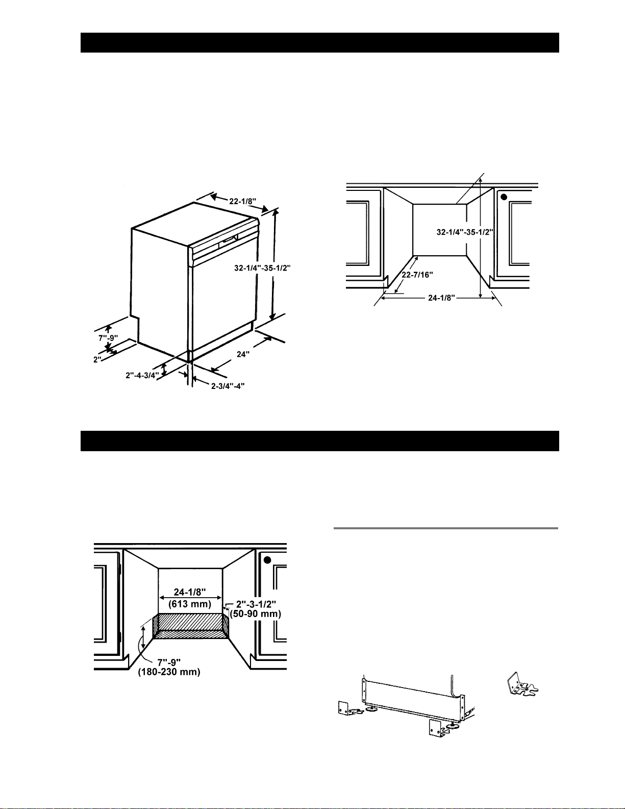
DIMENSIONSDIMENSIONS
DIMENSIONS
DIMENSIONSDIMENSIONS
UNIT DIMENSIONSUNIT DIMENSIONS
UNIT DIMENSIONS
UNIT DIMENSIONSUNIT DIMENSIONS
US European
Measure Measure
Height 32-1/4"–35-1/2" 825–900 mm
Width 24" 610 mm
Depth 22-7/16" 570 mm
Weight 104 lb 48 kg
CABINET OPENINGCABINET OPENING
CABINET OPENING
CABINET OPENINGCABINET OPENING
US European
Measure Measure
Height 32-1/4"–35-1/2" 825–900 mm
Width* 24" 610 mm
Depth 22-7/16" 570 mm
*
Models 1805 FI and 1895 do not have fill strips. The
width for these models is 23-1/2” (596 mm).
PREPPREP
PREP
PREPPREP
The best place for your dishwasher is in the kitchen
near the sink. This makes it easier to connect the water
and drain supply lines.
A built-in dishwasher must be enclosed on the top,
both sides and the back.
The kick plate supplied with your dishwasher will fit a 24"
opening. When using European standard installation, a
kick plate is available from your ASKO dealer. (Part
Numbers: White=8057528-0; Black=8057528-29)
The electrical and water supplies should enter through
the area indicated by the shading on the illustration
above. They should come through the right side of the
ARING ARING
ARING
ARING ARING
Under-Counter Space Needed
THE LTHE L
THE L
THE LTHE L
OCAOCA
OCA
OCAOCA
TIONTION
TION
TIONTION
machine, a maximum of 2” from the back wall and 7” to
9” from the floor, depending on the underneath cabinet
height.
Access holes must be round and smooth, and they
must be no bigger than 1-1/2" in diameter.
INSTINST
INST
INSTINST
(OPTIONAL)(OPTIONAL)
(OPTIONAL)
(OPTIONAL)(OPTIONAL)
When it is not possible to fasten the dishwasher to the
cabinet, you should install tip guards to prevent the
machine from tipping when the door is opened. The tip
guards can be attached either to the floor or the wall.
The tip guards should be mounted behind the machine,
19” apart (measuring center to center) and 18-1/2” from
the front of the machine. (Note: This measurement
could vary, depending on the thickness of the custom
panel, if any.)
ALLING ALLING
ALLING
ALLING ALLING
We recommend that you install tip
guards when it isn’t possible to fasten
the dishwasher to the cabinet.
Rear
THE THE
THE
THE THE
TIP GUTIP GU
TIP GU
TIP GUTIP GU
Tip Guards
(P/N 8070851)
ARDSARDS
ARDS
ARDSARDS
Page 3
Page 4
CORNER INSTCORNER INST
CORNER INST
CORNER INSTCORNER INST
If the dishwasher is installed in a corner, there must be
a minimum clearance of 2 inches (50 mm) from the
side wall so the door can open.
HOHO
T T
WW
AA
HO
HOHO
T
T T
TER SUPPLTER SUPPL
W
A
TER SUPPL
WW
AA
TER SUPPLTER SUPPL
ALLAALLA
ALLA
ALLAALLA
TIONTION
TION
TIONTION
YY
Y
YY
2” clearance
WARNING!
applicable sanitary, safety and plumbing codes in your
area.
The machine should preferably be connected to a hot
water supply. If a cold water supply is used, the washing
times will be longer but the performance will not be
affected.
The hot water supply line should be minimum 3/8" OD
copper tubing. The inlet valve has a 3/8" NPT female
connection.
Compression nut
Inlet valve, 3/8” OD
Plumbing connections must comply with
CONNECTIONSCONNECTIONS
CONNECTIONS
CONNECTIONSCONNECTIONS
Compression sleeve
3/8” OD copper
water line
90° compression elbow
3/8” NPT one end
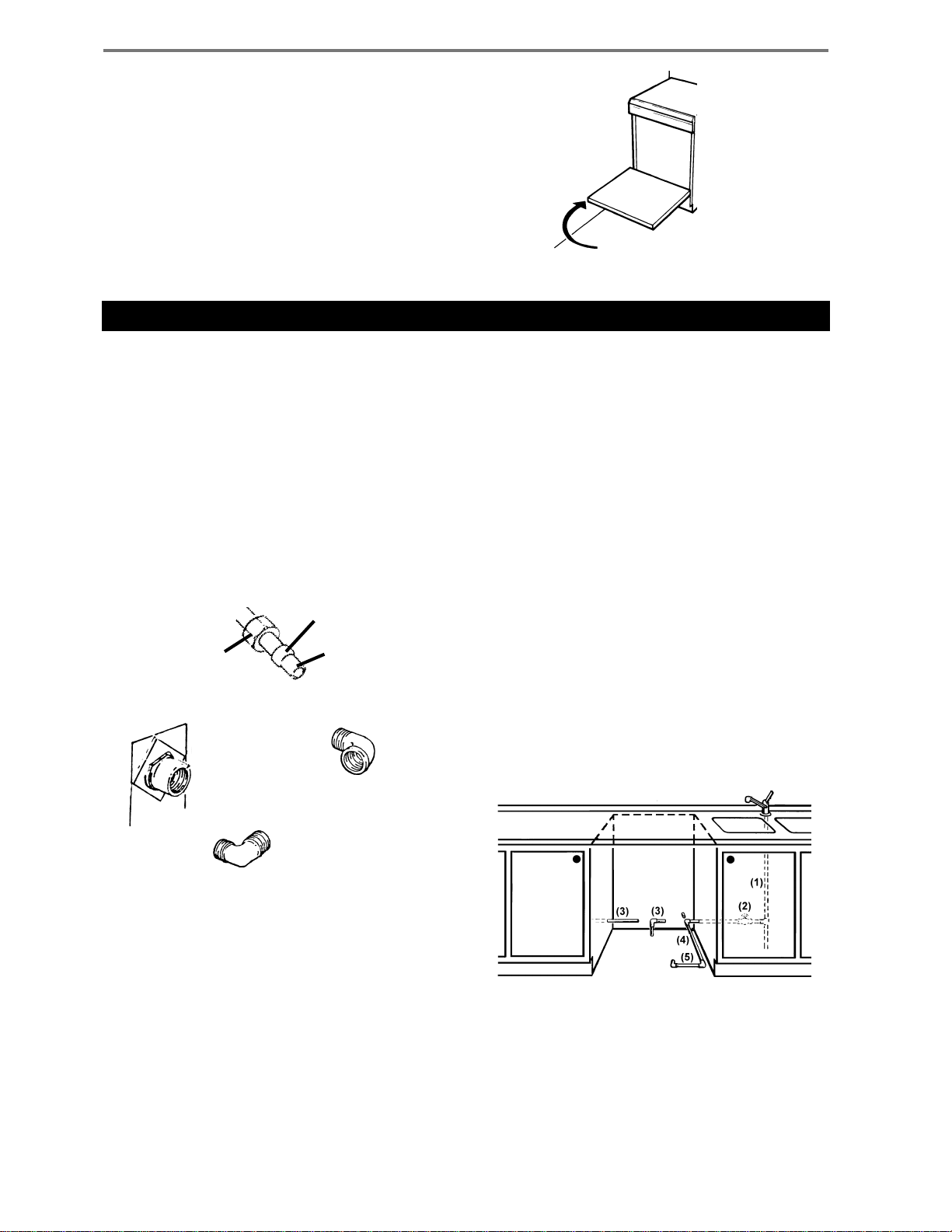
After determining where the water supply line will enter
the dishwasher, drill a 1" access hole and run the line
to the approximate inlet valve location shown in the figure
below. The inlet valve is on the right front of the machine,
so the water line should be placed on the right side.
If you use soft copper line, leave the tube straight out in
the opening to slide the dishwasher in. Bend the tube
into position after the dishwasher is slid into the cabinet
opening.
For service convenience, a shut-off valve (not supplied)
should be installed in the supply line in an easily
accessible location (such as, beneath the sink) or in
the supply line near the dishwasher fill valve.
It is important that the water supply line and the shut-off
valve have a sufficient flow volume. At last 3 gallons (12
liters) per minute must be able to pass through the
line. The water pressure should be 18-176 psi.
WARNING!
In order to prevent heat damage to the inlet valve, all
solder connections must be made before the water
line is connected to the dishwasher.
INSTINST
INST
INSTINST
ALLAALLA
ALLA
ALLAALLA
TIONTION
TION
TIONTION
Page 4
90° street elbow
(1) Hot water supply
(2) Shut-off valve
(not supplied)
NOTE:
You should only install the number 4 tubing
before you push the machine into position.
Tubing number 5 is to be fitted when the
machine is in position.
(3) Alternate locations
(4) & (5) Tubing
Page 5

DRAIN SUPPLDRAIN SUPPL
DRAIN SUPPL
DRAIN SUPPLDRAIN SUPPL
YY
Y
YY
ASKO provides a 7/8” drain hose which is connected to
the back of the unit to form a high loop. If additional
drain hose is needed, please purchase an additional
ASKO drain hose and joint it to the provided hose with a
7/8” copper tube.
NOTE:
The access hole for the drain line should be 1-1/2".
The end of the drain line is 1/2”, but it is adjustable to
7/8”, 3/4”, 5/8”. If the drain connection is larger than
1/2”, you can easily cut the drain line to fit the connection.
The illustrations to the right show three ways to connect
the drain supply line.
THE HIGH LTHE HIGH L
THE HIGH L
THE HIGH LTHE HIGH L
All ASKO dishwashers have drain hoses attached to
the drain pump and fastened to the top back of the unit.
This gives the drain hose an
is necessary for proper draining. The drain hose is
fastened at the best high loop height with a plastic zip
tie. T o eliminate potential drain problems, simply leave
this hose in place
IMPORIMPOR
IMPOR
IMPORIMPOR
REMEMBER:REMEMBER:
REMEMBER:
REMEMBER:REMEMBER:
♦ Failure to provide the proper drain connection height
♦ No part of the drain hose should be higher than 35"
♦ The hose must not be drawn straight to a floor well
♦ The drain hose can be extended to a maximum
♦ If the drain line is going to be connected to a waste
♦ Do not use fittings smaller than 7/8”; otherwise the
Do not use any fittings anywhere in the drain
line that are less than 7/8" ID.
OOPOOP
OOP
OOPOOP
automatic high loop
.
TT
ANT ANT
T
ANT
TT
ANT ANT
(minimum of 20" above the bottom of the dishwasher
base) or a 20" high loop will result in improper
drainage, which will damage the machine.
from the bottom of the dishwasher.
or its equivalent because it might function as a
siphon and empty the machine.
length of 10 feet. Joints and jointed tubes, if any,
must have a minimum 7/8" ID.
disposer, be sure to remove the knockout or plug
from the fitting on the disposer before connecting
the drain line.
water may not drain properly.
THINGS THINGS
THINGS
THINGS THINGS
TT
T
TT
OO
O
OO
, which
THREE THREE
THREE
THREE THREE
DRAIN CONNECTIONSDRAIN CONNECTIONS
DRAIN CONNECTIONS
DRAIN CONNECTIONSDRAIN CONNECTIONS
A.)T ypical connection to sink plumbing before
trap (high loop drain)
B.)Connection to air gap then to the trap
C.)Connection to waste disposer with air gap
WW
W
WW
AA
A
AA
YY
Y
YY
S S
S
S S
TT
T
TT
O INSTO INST
O INST
O INSTO INST
ALLALL
ALL
ALLALL
When the installation is ready, open the supply valve
and let the pressure act for a while. Then check that all
connections are tight and there are no leaks.
NOTE:
Don’t forget to remove the knockout
or plug from the disposer fitting.
Page 5
Page 6

ELECTRICAL CONNECTIONSELECTRICAL CONNECTIONS
ELECTRICAL CONNECTIONS
ELECTRICAL CONNECTIONSELECTRICAL CONNECTIONS
WARNING!
electrical appliance, be sure the electrical power
has been turned off at the breaker/fuse box.
WARNING!
supply and place a tag at the disconnect switch
indicating that you are working on the circuit.
WARNING!
connections must comply with the applicable
portions of the national electrical code and/or
other local electrical codes.
The electrical supply must be a 110–120 volts, 15 or 20
amp properly grounded circuit. No other appliance or
outlets should be on this circuit.
GRGR
OUNDING INSTROUNDING INSTR
GR
OUNDING INSTR
GRGR
OUNDING INSTROUNDING INSTR
This unit must be grounded to operate properly. It must
be connected to a grounded metal, permanent wiring
system, or an equipment-grounding conductor must
be run with the circuit conductors and connected to the
equipment-grounding terminal or lead of the appliance.
PREPPREP
PREP
PREPPREP
Before working on wiring for any
Disconnect electrical power
Electrical and grounding
UCTIONSUCTIONS
UCTIONS
UCTIONSUCTIONS
ARING ARING
ARING
ARING ARING
THE DISHWTHE DISHW
THE DISHW
THE DISHWTHE DISHW
ASHER FOR INSTASHER FOR INST
ASHER FOR INST
ASHER FOR INSTASHER FOR INST
NOTE:
Damage to the dishwasher could occur if it is not
properly grounded.
WARNING!
drain line and branch circuit wiring do not touch
any exposed terminals of dishwasher wiring.
Access holes must not be larger
than 1-1/2” in diameter with no sharp
edges.
Make sure the water supply line,
ALLAALLA
ALLA
ALLAALLA
TIONTION
TION
TIONTION
At this point the styrofoam, plastic wrap, and the wood
pallet (base) should be removed from the dishwasher.
Now is an excellent time to inspect for any shipping
damage. Should you find any damage, you should
report it to your dealer or builder
Be sure to remove the toe kick and toe kick insulation
which are wrapped in heavy brown paper and packed
inside the dishwasher.
THE FILL STRIPSTHE FILL STRIPS
THE FILL STRIPS
THE FILL STRIPSTHE FILL STRIPS
All ASKO dishwashers (except Models 1805FI and 1895)
have color-coded fill strips to finish off the installation.
To prevent damage to the machine, be sure to remove
the shipping screws that secure the fill strips to the
access panel. These screws are to be thrown away . Do
not replace them into the access panel.
immediately
WARNING!
Do not screw the fill
strips back to the
lower access panel;
otherwise, the
machine will have to
be uninstalled if
service is necessary.
.
SLIDES FOR REAR LEGSSLIDES FOR REAR LEGS
SLIDES FOR REAR LEGS
SLIDES FOR REAR LEGSSLIDES FOR REAR LEGS
The unit comes with two white plastic slides for the rear
legs to protect the kitchen floor from being damaged
when you slide the unit into place. The slides simply
snap onto the bottom of the rear legs.
Protective slides for rear
legs simply snap onto the
bottom of the legs.
REMOREMO
REMO
REMOREMO
T o remove the access panel, first remove the two screws
on each side of the access panel. There are two tabs at
the top of the access panel that hold the panel in place
against the guard plate. To remove the panel, you must
slide it down below these tabs.
REMOREMO
REMO
REMOREMO
BRABRA
BRA
BRABRA
To remove the toe kick brackets, hold the small metal
spring tab on the outer edge of the base pan toward the
outside of the machine. Continue holding the tab as
you pull straight out on the bracket. (
stubborn because it’s in guide slots on the base pan.)
VING VING
VING
VING VING
VING VING
VING
VING VING
CKETSCKETS
CKETS
CKETSCKETS
THE THE
THE
THE THE
THE THE
THE
THE THE
AA
CCESS PCCESS P
A
CCESS P
AA
CCESS PCCESS P
TT
OE KICKOE KICK
T
OE KICK
TT
OE KICKOE KICK
Note:
ANELANEL
ANEL
ANELANEL
It may be
Access
Panel
NOTE:
Page 6
Fill
Strip
Toe kick bracket
If the cabinet opening is European measurement
(23-1/2 inches [600 mm]), remove the fill strips
to fit the dishwasher into the opening.
Page 7

REMOREMO
REMO
REMOREMO
There are four screws that hold the guard plate in place,
two on the upper/underneath side and two on the front.
To remove the guard plate, first remove the toe kick
brackets (see page 6). Then remove the two screws on
the upper/underneath side of the guard plate. Next,
remove the two screws from the front side of the guard
plate.
VING VING
VING
VING VING
Guard plate
THE GUTHE GU
THE GU
THE GUTHE GU
ARD PLAARD PLA
ARD PLA
ARD PLAARD PLA
TETE
TE
TETE
After the screws are removed, grip the bottom of the
guard plate and pull it toward you to remove it. You can
now access the inlet valve, electrical connection, and
drain pump and hose, as illustrated below.
Remove the two
screws on each
side of the guard
plate.
MOMO
VING VING
MO
VING
MOMO
VING VING
1. Position the machine in front of the cabinet
opening.
2. Make the height adjustment while the dishwasher
is in front of the opening.
3. Pull out the drain hose to ensure there are no sharp
bends.
4. On the bottom rear of the dishwasher there is a
black ziptie around the rubber buffer that holds the
circulation pump in place. Cut the ziptie and remove
it.
5. Start to feed water, electric, and drain lines into
position.
6. Make sure you’ve put the protective slides on the
rear legs to prevent damaging the floor when you
slide the unit into place (see page 6).
7. Gently slide the unit into the dishwasher opening.
As you do this, feed the drain line into the drain line
hole. Also, feed the electrical and water lines to the
THE MATHE MA
THE MA
THE MATHE MA
CHINE INTCHINE INT
CHINE INT
CHINE INTCHINE INT
Remove the two
screws on each
side of the guard
plate.
O PLAO PLA
O PLA
O PLAO PLA
As you slide the unit into place, feed the drain line into
the drain line hole and the electrical and water lines to
the right front of the dishwasher.
CECE
CE
CECE
WARNING!
CONNECTING THE ELECTRIC CABLECONNECTING THE ELECTRIC CABLE
CONNECTING THE ELECTRIC CABLE
CONNECTING THE ELECTRIC CABLECONNECTING THE ELECTRIC CABLE
WARNING!
1. Connect supply cable with
a UL-listed strain relief
bushing (if nonmetallic
cable is to be used).
2. Connect branch circuit
white lead to white lead on
main terminal block.
Before starting this procedure, be sure
3. Connect branch circuit black lead to brown lead on
main terminal block.
4. Connect ground wire to ground on terminal block.
Be careful of sharp edges.
Page 7
Page 8

CONNECTING CONNECTING
CONNECTING
CONNECTING CONNECTING
In order to prevent heat damage to the inlet valve, all
solder connections must be made before the water
line is connected to the dishwasher.
Flush the water supply line prior to connecting it to the
inlet valve of the machine.
The unit has a float switch in the base pan to protect
against flooding. If the inlet valve connection is not
seated properly, water may leak into the base pan and
activate the float switch. Make sure the connection is
seated and not leaking before completing the installation.
It is important that the water supply line and the shut-off
valve have a sufficient flow volume. At last 3 gallons (12
liters) per minute must be able to pass through the
line. The water pressure should be 18-176 psi.
If the water line is installed properly, there is no need to
seal the connection with Teflon™ tape.
Bend the tube into position after the dishwasher is in
the cabinet opening. It’s best to use a tube bender to
keep the line from kinking.
TESTING FOR LEAKSTESTING FOR LEAKS
TESTING FOR LEAKS
TESTING FOR LEAKSTESTING FOR LEAKS
1. Turn on the water supply and check for leaks.
2. Turn the power on at breaker/fuse box and test the
dishwasher operation by running a Rinse cycle.
(This should take about four minutes.)
3. Turn off the electrical power and check for leaks
THE THE
THE
THE THE
WW
AA
TER SUPPLTER SUPPL
W
A
TER SUPPL
WW
AA
TER SUPPLTER SUPPL
YY
Y
YY
(1) Hot water supply
(2) Shut-off valve
NOTE:
4. Make sure that no kinks have developed in the drain
If there are no leaks and the dishwasher seems to be
working properly, continue with the installation.
You should only install the number 4 tubing
before you push the machine into position.
Tubing number 5 is to be fitted when the
machine is in position.
under the dishwasher.
lines.
(3) Alternate locations
(4) & (5) Tubing
ADJUSTING THE LEVELING LEGSADJUSTING THE LEVELING LEGS
ADJUSTING THE LEVELING LEGS
ADJUSTING THE LEVELING LEGSADJUSTING THE LEVELING LEGS
Now that all the connections are made and the machine
is in place under the cabinet, you should make the final
height adjustment.
1. Using a 1/2” (12 mm) wrench, adjust the locking
nuts until the machine is level. (The machine may
have an inclination of 2° maximum without affecting
its performance.)
FASTENING THE DISHWASHER TO THE CABINETFASTENING THE DISHWASHER TO THE CABINET
FASTENING THE DISHWASHER TO THE CABINET
FASTENING THE DISHWASHER TO THE CABINETFASTENING THE DISHWASHER TO THE CABINET
It’s necessary to fasten the dishwasher to the cabinet
so it won’t tilt when the door is opened or if something
heavy is placed on the door. Use only the stainless
steel screws provided with the machine.
1. Use option A for U.S. or European standard
installations. Use option B only for European
standard installations.
2. Cover the screw heads with the plastic plugs
provided with the machine.
3. When the machine is properly attached, check that
the feet are tight against the floor and that the
machine is level.
NOTE:
When it is not possible to attach the dishwasher
to the cabinet, you should install tip guards.
(See “Tip Guards” on page 2.)
2. When the feet are properly
adjusted, tighten the locking
nuts to the base pan.
NOTE:
When adjusting the unit lower than 33-1/4” the
toe kick has to be modified; the holes for the
access panel and fill strips need to be
elongated.
NOTE:
Option A can be used for U.S. or European
installations. Use option B for European
standard installations only.
Page 8
Page 9

REPLAREPLA
REPLA
REPLAREPLA
CING CING
CING
CING CING
THE THE
THE
THE THE
TT
OE KICK BRAOE KICK BRA
T
OE KICK BRA
TT
OE KICK BRAOE KICK BRA
CKETSCKETS
CKETS
CKETSCKETS
After you replace the guard plate (see page 7), you need
to replace the toe kick brackets. While holding the spring
tab on the base pan toward the outside of the machine,
slide the bracket into the
slots on the guard plate
and work it between
the guide slots on
the base pan.
INSTINST
INST
INSTINST
Once you have the toe kick bracket in place, you can
install the toe kick, as follows:
1. If you have not done so, remove the toe kick and felt
2. Lay the insulation on the back side of the toe kick to
3. Peel the adhesive protection strip off the insulation
4. Positioning the notches on the toe kick at the edge
5. Screw the toe kick to the toe kick brackets.
ALLING ALLING
ALLING
ALLING ALLING
insulation from the brown paper packaging.
make sure it fits properly.
and press it firmly to the back side of the toe kick,
making sure you don’t cover any slots on the toe
kick.
of the access panel, slide the toe kick up behind
the access panel then let it slide to the floor.
THE THE
THE
THE THE
Guard plate
TT
OE KICKOE KICK
T
OE KICK
TT
OE KICKOE KICK
Adjusting the Bracket DepthAdjusting the Bracket Depth
Adjusting the Bracket Depth
Adjusting the Bracket DepthAdjusting the Bracket Depth
Y ou will have to adjust the bracket depth to allow for the
thickness of the toe kick. To do this, first measure the
thickness of the toe kick. Then press the spring tab on
the sides of the base pan toward the outside of the
machine and carefully pull or push the bracket to the
required depth less the thickness of the toe kick.
NOTE:
Adjusting the Height onAdjusting the Height on
Adjusting the Height on
Adjusting the Height onAdjusting the Height on
Models 1805FI and 1895Models 1805FI and 1895
Models 1805FI and 1895
Models 1805FI and 1895Models 1805FI and 1895
These models come with two toe kicks. Use the
mounted toe kick if the machine will be 32-1/2” to
33-1/2” high. If it will be higher, use the toe kick
packed inside the dishwasher.
The toe kick has extended screw slots that allow you to
adjust the height. Position the toe kick so it touches the
floor and tighten the screws.
Make sure the toe kick bracket is securely
inside the guides on the base pan.
Extended screw slots
CHANGING CHANGING
CHANGING
CHANGING CHANGING
WARNING!
appliance, be sure the electrical power has been
turned off at the breaker/fuse box.
Refer to the illustration at right for instruction references.
1. Remove the lower access panel with standard or
20 torx screwdriver.
2. Using needlenose pliers, remove the plastic plugs
around the edges of the access panel and upper
door panel. You may discard the plugs.
3. Using the screws provided with the trim kit, loosely
secure parts A and C to the upper door panel.
4. Slide the upper panel into the trim kit grooves.
5. Tighten the screws holding parts A and C.
6. Secure part B and tighten screws.
7. Loosely screw part E to the lower access panel.
8. Slide the custom panel into trim kit channels and
tighten the screw to part E.
9. Secure part D of the trim kit and tighten the screws.
10. Secure the lower access panel to the dishwasher.
11. Drop the access panel to line up with the lower
holes on the guard plate.
Before working on any electrical
THE FRTHE FR
THE FR
THE FRTHE FR
ONT PONT P
ONT P
ONT PONT P
ANELSANELS
ANELS
ANELSANELS
NOTE:
After you install the front panels, you should test the
door before you push the dishwasher into the cabinet
opening. If the door doesn’t open properly, you may
need to adjust the door springs (see page 10).
The stainless steel panels do not have holes
for custom trim. You have to drill the holes.
Panel Trim Kit
Page 9
Page 10

FITTING FITTING
FITTING
FITTING FITTING
THE THE
THE
THE THE
1805FI1805FI
1805FI
1805FI1805FI
CUST CUST
CUST
CUST CUST
OM DOOR POM DOOR P
OM DOOR P
OM DOOR POM DOOR P
ANELANEL
ANEL
ANELANEL
The 1805FI can only be installed with a custom door
panel that extends from the toe kick to the counter top.
The unit comes with everything needed to make
installing the door panel easy. The door is predrilled for
the panel’s mounting screws.
The custom panel should be at least 1/4” thick.
ITEMS PRITEMS PR
ITEMS PR
ITEMS PRITEMS PR
♦ Two 3/8” screws (B)
♦ One protective tape (C)
♦ Four adhesive-backed plastic spacer washers (D)
♦ Four 1-3/4” screws (G)
INSTINST
INST
INSTINST
Before fitting the custom panel, the dishwasher must
be installed underneath the cabinet. After you’ve made
the required measurements, pull the machine out again
to install the panel.
Refer to the illustration at right for instruction references.
1. Fit the handle (A) onto the panel according to the
manufacturer’s instructions. (
should be used rather than a knob, because a knob
does not provide enough grip.)
2. Peel the adhesive backing off the washers and place
them in line with the four keyholes (C) on the metal
front of the dishwasher door.
3. Loosen the screws (D) on the outer edges of the
dishwasher door.
4. Pull the turbo fan exhaust frame (E) down until the
lower edge aligns with the lower edge of the cabinets
and tighten the screws. Next, snap the plastic duct
into the turbo fan exhaust vent.
OO
VIDED VIDED
O
VIDED
OO
VIDED VIDED
ALLING ALLING
ALLING
ALLING ALLING
WITH WITH
WITH
WITH WITH
THE CUSTTHE CUST
THE CUST
THE CUSTTHE CUST
THE UNITTHE UNIT
THE UNIT
THE UNITTHE UNIT
NOTE:
OM POM P
OM P
OM POM P
A handle
ANELANEL
ANEL
ANELANEL
CUSTCUST
CUST
CUSTCUST
Width: 23-3/8” (597 mm)
Height: 28-1/8”–30-1/8” (714 mm–765 mm)
Thickness: 1/4” (25 mm)
Weight: Up to 22 lb.
NOTE:
NOTE:
OM POM P
OM P
OM POM P
Specifications subject to change without
notice.
Heavy-duty door springs can be purchased for
wooden door panels weighing over twelve
pounds. (P/N 8071323-77).
Installing the 1805FI Custom Panel
ANEL DIMENSIONSANEL DIMENSIONS
ANEL DIMENSIONS
ANEL DIMENSIONSANEL DIMENSIONS
(Measured from the top of the panel to
the lower edge of the kitchen cabinet.)
WARNING!
The custom panel must not
obstruct the turbo fan exhaust.
See step 4 above for instructions
on how to adjust the fan exhaust.
5. The two short screws (B) go into the back of the
panel, 16-3/16” from the upper edge of the panel
and 5/8” from the outer edges. Insert the short
screws into the panel, leaving 1/8” of space between
the screw head and the panel.
6. Hook the panel screws (F) into the keyholes (C) on
the dishwasher door.
7. Push the panel upwards until the lower edge aligns
with the lower edge of the cabinets.
NOTE:
than 2-15/16” below the bottom of the dishwasher
door. Otherwise, it will strike the toe kick and
damage the machine and/or the panel.
8. Open the door and tighten the screws (F) inside.
9. Remove the backing from the protective tape and
apply it on the bottom edge of the panel, in front of
the exhaust vent.
The custom panel should not extend more
ADJUSTING THE DOOR SPRINGSADJUSTING THE DOOR SPRINGS
ADJUSTING THE DOOR SPRINGS
ADJUSTING THE DOOR SPRINGSADJUSTING THE DOOR SPRINGS
After you install the custom panel,
make sure the door can be
opened at any angle. If it tends to
fall down, pull out the machine
and tension the door springs on
the sides of the machine by
moving them one hole farther
back or by twisting the spring to
make it shorter. If that doesn’t resolve the problem, you
may need to purchase the heavy-duty door springs (Part
Number 8071323-77).
FASTENING THE DISHWASHERFASTENING THE DISHWASHER
FASTENING THE DISHWASHER
FASTENING THE DISHWASHERFASTENING THE DISHWASHER
TO THE CABINETTO THE CABINET
TO THE CABINET
TO THE CABINETTO THE CABINET
Refer to page 8.
Page 10
Page 11

1805FI CUST1805FI CUST
1805FI CUST
1805FI CUST1805FI CUST
OM POM P
OM P
OM POM P
ANEL INSTANEL INST
ANEL INST
ANEL INSTANEL INST
ALLAALLA
ALLA
ALLAALLA
TION OPTIONSTION OPTIONS
TION OPTIONS
TION OPTIONSTION OPTIONS
4-inc4-inc
4-inc
4-inc4-inc
Custom panels the same height as the
dishwasher door
If the custom panel is the same height as the
dishwasher door, a 2” decorative fill strip or pull-out
cutting board must be used to fill the area between the
panel and the counter top (as illustrated below).
h h
TT
oe Kicoe Kic
h
T
oe Kic
h h
TT
oe Kicoe Kic
A 2” decorative fill strip or cutting board is
required when the door panel is the same
height as the dishwasher door.
k Installak Installa
k Installa
k Installak Installa
tionstions
tions
tionstions
If you install the door panel to reach the cabinet top, we
recommend that you install a 2” support strip between
the upper edge of the dishwasher and the counter to
hide the top of the dishwasher and further reduce water
noise.
A 2” support strip
hides the top of the
dishwasher and
further reduces
water noise.
6-inc6-inc
6-inc
6-inc6-inc
For 6” toe kick installations, the decorative fill strips or
support strips are unnecessary.
h h
h
h h
TT
T
TT
oe Kicoe Kic
oe Kic
oe Kicoe Kic
k Installak Installa
k Installa
k Installak Installa
tionstions
tions
tionstions
Custom panels that extend to cabinet top
Another installation option for a 4” toe kick is to extend
the custom panel to the cabinet top (as illustrated
below), which eliminates the need for a decorative fill
strip.
Panel extends from toe kick to cabinet top.
30-1/8"
(765 mm)
23-1/2"
(596 mm)
4"
(100 mm)
23-5/8"
(599 mm)
With this installation, the door
panel extends 2” above the
dishwasher control panel, as
illustrated. This makes setting
the controls slightly less
convenient, but the aesthetic
benefits seem to outweigh this
small disadvantage.
2"
(50 mm)
28-1/8"
(714 mm)
23-1/2"
(596 mm)
6"
(150 mm)
23-5/8"
(599 mm)
No fill strips or support strips are
necessary with a 6” toe kick.
Page 11
Page 12

FITTING FITTING
FITTING
FITTING FITTING
PP
ANEL ON MODEL 1895ANEL ON MODEL 1895
P
ANEL ON MODEL 1895
PP
ANEL ON MODEL 1895ANEL ON MODEL 1895
THE SEMI-INTEGRATHE SEMI-INTEGRA
THE SEMI-INTEGRA
THE SEMI-INTEGRATHE SEMI-INTEGRA
TED CUSTTED CUST
TED CUST
TED CUSTTED CUST
OM DOOROM DOOR
OM DOOR
OM DOOROM DOOR
Model 1895 was designed to easily accommodate
custom panels. If you use the 4” toe kick, a 2” filler strip
or a pullout cutting board above the unit will be
necessary.
The opening width for Model 1895 is 23-5/8” (600 mm),
which is 3/8” narrower than standard domestic
dishwashers.
ITEMS PRITEMS PR
ITEMS PR
ITEMS PRITEMS PR
♦ Two short screws (D)
♦ Four long screws (E)
♦ Four adhesive-backed plastic spacer washers (D)
♦ One protective tape
INSTINST
INST
INSTINST
Before fitting the custom panel, the dishwasher must
be installed underneath the cabinet. After you’ve made
the required measurements, pull the machine out again
to install the panel.
Refer to the illustration at right for instruction references.
1. Loosen the screws (A) on the outer edges of the
dishwasher door.
2. Pull the turbo fan exhaust frame (B) down until the
lower edge aligns with the lower edge of the cabinets
and tighten the screws (A). Next, snap the plastic
duct securely into the turbo fan exhaust vent.
OO
VIDED VIDED
O
VIDED
OO
VIDED VIDED
ALLING ALLING
ALLING
ALLING ALLING
WITH WITH
WITH
WITH WITH
THE PTHE P
THE P
THE PTHE P
THE UNITTHE UNIT
THE UNIT
THE UNITTHE UNIT
ANELANEL
ANEL
ANELANEL
WW
OODEN POODEN P
W
OODEN P
WW
OODEN POODEN P
Width: 23-3/8” (594 mm)
Height: 22-9/16”–24” (573 mm–609 mm)
Thickness: 3/4” (19 mm) (to be flush with the control
Weight: Up to 22 lbs.
NOTE:
NOTE:
Specifications subject to change without
notice.
Heavy-duty door springs can be purchased for
wooden door panels weighing over twelve
pounds. (P/N 8071323-77).
Installing the 1895 Custom Panel
ANEL DIMENSIONSANEL DIMENSIONS
ANEL DIMENSIONS
ANEL DIMENSIONSANEL DIMENSIONS
panel)
WARNING!
The custom panel must not
obstruct the turbo fan exhaust.
See step 2 above for instructions
on how to adjust the fan exhaust.
3. The spacers (C) between the control panel and the
custom door panel allow you to accommodate the height
of the custom panel (from 1” up to 1-7/16”). T o remove a
spacer, loosen the nuts at the bottom of the spacers
and remove as many as necessary. Screw the nuts
back on and cut off any protruding parts of the plastic
screws. (If necessary, you can omit the spacers.)
4. To mark where to put the two short screws (E), hold
the custom panel in place against the front of the
dishwasher door and measure 16-1/8” from the top of
the dishwasher, marking that distance on both sides
of the custom panel. Next, measure 5/8” from the edges
and mark that across the first measurement.
5. Insert the short screws (E) into the back of the
wooden panel where you marked, leaving 1/8” of
space between the screw heads and the panel.
6. Insert the screw heads (E) into the lower part of the
keyholes (D) and push the panel upward until the
door aligns with the cabinets.
7. Holding the custom panel in place, open the
dishwasher door and tighten the four screws (F)
that secure the panel.
ADJUSTING THE DOOR SPRINGSADJUSTING THE DOOR SPRINGS
ADJUSTING THE DOOR SPRINGS
ADJUSTING THE DOOR SPRINGSADJUSTING THE DOOR SPRINGS
After you install the custom
panel, make sure the door can
be opened at any angle. If it
tends to fall down, pull out the
machine and tension the door
springs on the sides of the
machine by moving them one
hole farther back or by twisting
the spring to make it shorter. If
that doesn’t resolve the problem, you may need to
purchase the heavy-duty door springs (Part Number
8071323-77).
FASTENING THE DISHWASHERFASTENING THE DISHWASHER
FASTENING THE DISHWASHER
FASTENING THE DISHWASHERFASTENING THE DISHWASHER
TO THE CABINETTO THE CABINET
TO THE CABINET
TO THE CABINETTO THE CABINET
Refer to page 8.
Page 12
 Loading...