

Page 1

ASHLY
SC-63/SC"66A PARAMETRIC EQUALIZERS
OPERATING INSTRUCTIONS
ASHLY AUDIO INC.
Page 2

TABLE OF CONTENTS
1. INTRODUCTION / UNPACKING 2
2. FRONT PANEL LAYOUT 3
3. BACK PANEL LAYOUT 4
4. INPUT, OUTPUT, AND POWER CONNECTIONS 4
5. EXPLANATION OF PARAMETRIC EQ AND OUR CONTROLS 5
6. FEEDBACK STEP BY STEP SETUP INSTRUCTIONS 7
7. NARROW BAND STEP BY STEP SETUP INSTRUCTIONS 8
8. MEDIUM TO WIDE BAND STEP BY STEP SETUP INSTRUCTIONS 9
9. APPLICATION AND OPERATION FOR SOUND REINFORCEMENT 9
10. OPERATION FOR USE AS AN INSTRUMENT TONE CONTROL 11
11. APPLICATION AND OPERATION FOR RECORDING 11
12. APPLICATION AND OPERATION FOR BROADCASTING 12
Page
13. APPLICATION AND OPERATION FOR DISCOTHEQUES 12
14. APPLICATION AND OPERATION FOR MOTION PICTURE SOUND & TV 13
15. BLOCK DIAGRAMS 14
16. CIRCUIT DESCRIPTION 14
17. DEFINITION OF TERMS 15
18. TROUBLE SHOOTING TIPS 18
19. SPECIFICATIONS 19
20. GRAPH OF KEYBOARD / MUSIC STAFF FREQUENCY NUMBERS 20
Page 3

We thank you for your expression of confidence in Ashly products. The unit
you have purchased is protected by a two year warranty. To establish the
warranty, be sure to fill out and mail the warranty card attached to your
product.
Fill out the information below for your records.
Model Number Serial Number
Dealer Date of Purchase
Phone
Salesman
Other Information:
Page 4

INTRODUCTION
As soon as reproduced audio appeared on the scene, the need for tone controls
was apparent; a common problem has always been loss of frequency extremes.
Early equalizers were simple bass and treble controls which were used to
extend frequency response a bit. This type of tone control is powerless when
dealing with specialized acoustical problems. Movie people of the thirties
designed equalizers to deal with mid-range frequencies and used them for
specific problems of intelligibility. These "dialogue equalizers" along with
other special effects devices such as sound effects filters are examples of
equalizers designed to solve specific problems.
Graphic Equalizers were the first universal tone controls, providing a piece-
wise approximation of total frequency response. All of these equalizers have
a common limitation, some of the characteristics of equalization are fixed.
For example, the center frequency and sharpness for each band of a graphic are
pre-determined. This leads to an immediate frustration because these
characteristics are never exactly appropriate. (What do you do when you need
a fader right between two sliders on a graphic?)
In the late sixtys, the first parametric equalizers were developed by George
Massenburg at ITI. Parametrics provide independent and continuous adjustment
of all three possible characteristics: amplitude, center frequency, and
bandwidth. As a result, virtually any desired frequency response may be
obtained with no restrictions imposed by the equalizer itself.
The Ashly Audio SC-63 and SC-66A parametric equalizers are the result of years
of research and development. They are the most flexible and powerful tool yet
developed for modifying audio frequency response. As such, they can solve
audio problems previously considered insurmountable, and can provide tone
control action to exactly suit particular needs. Of course, they also require
a greater understanding of the equalization process than simpler tone
controls,
We ask that you please read this instruction manual thoroughly before
operation so that you may realize all the features and benefits that the SC-53
and SC-66A parametric equalizers have to offer.
UNPACKING
As a part of our system of quality control every Ashly product is carefully
inspected before leaving the factory to ensure flawless appearance. After
unpacking, please inspect for any physical damage. Save the shipping carton
and all packing materials, as they were carefully designed to reduce to a
minimum the possibility of transportation damage should the unit again require
packing and shipping. In the event that damage has occurred, immediately
notify your dealer so that a written claim to cover the damages can be
initiated.
THE RIGHT TO ANY CLAIM AGAINST A PUBLIC CARRIER CAN BE FORFEITED IF THE
CARRIER IS NOT NOTIFIED PROMPTLY AND IF THE SHIPPING CARTON AND PACKING
MATERIALS ARE NOT AVAILABLE FOR INSPECTION BY THE CARRIER. SAVE ALL PACKING
MATERIALS UNTIL THE CLAIM HAS BEEN SETTLED.
Page 5
MODEL SC-63
< GAIN 1
o
Page 6
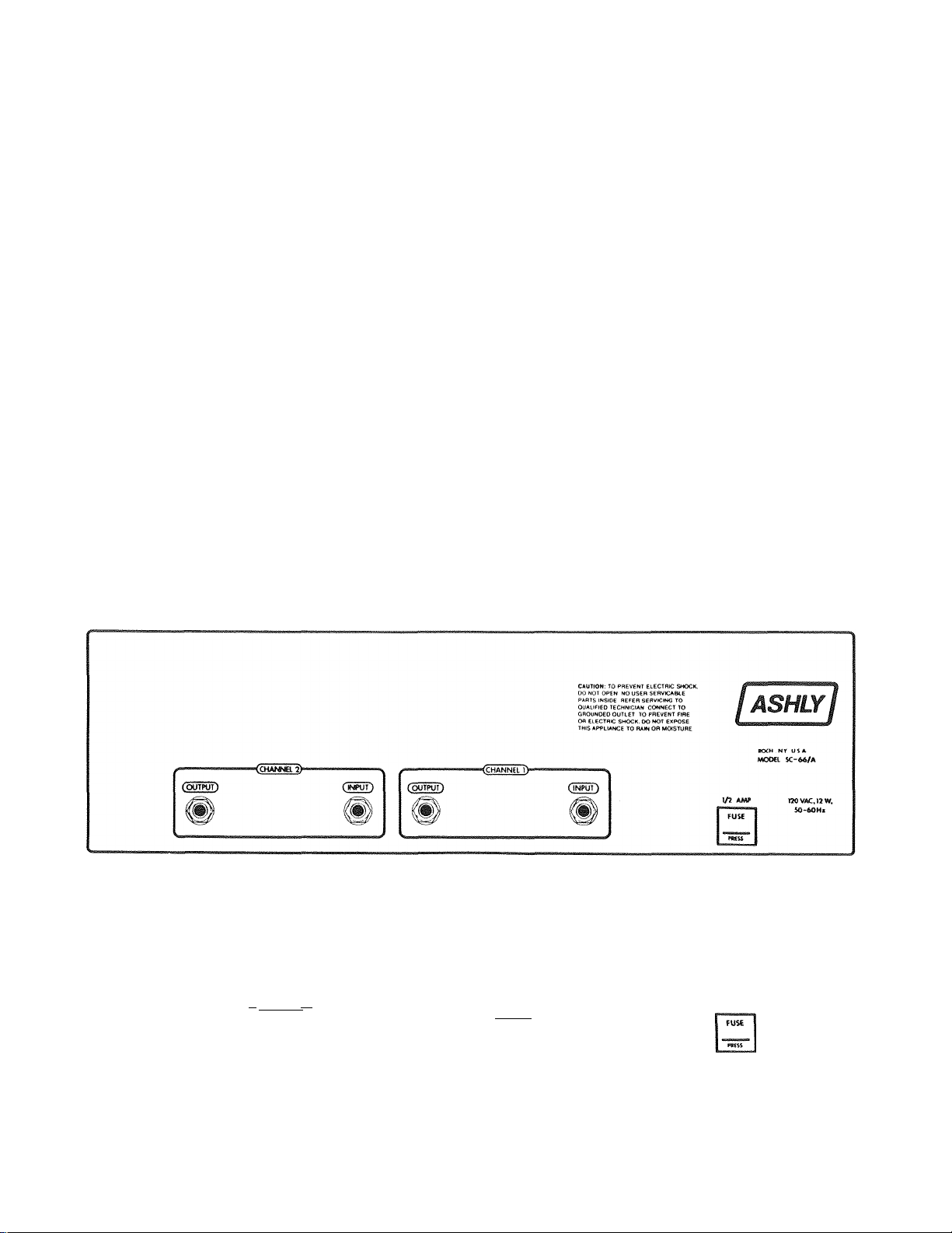
INPUT, OUTPUT, AND POWER CONNECTIONS
This equalizer should be connected to a 3 wire grounded outlet supplying 120
Volts, 50-60 Hz. Power consumption is 12 watts.
The INPUT is a 10K ohm active balanced type on a standard stereo phone plug.
The (+) or in-phase connection is on the tip and the (-) or out-of-phase
connection is on the ring. When feeding the equalizer from unbalanced
sources, connect the signal hot to the tip ( + ) and the signal ground to the
ring (-). To use the input as a common unbalanced type, simply use a mono
phone plug in the usual way. (See Definition Of Terms, "Wiring", page 17.)
The OUTPUT connections are standard 1/4" phone jacks and mate with a standard
phone plug such as a switchcraft 280. For rack mounted unbalanced audio
systems the output ground may be separated from the case ground by using a
stereo phone plug for the output connection. The output ground is then wired
to the ring of the stereo phone plug for the output connection. The output
ground is then wired to the ring of the stereo plugs rather than the sleeve.
In this manner, ground loops in the rack may be eliminated. This output can
be fed to a balanced input by wiring the ( + ) input to the tip, the (-) input
to the ring, and the shield to ground.
If this equalizer is used in a monaural system, channels 1 and 2 of the SC-66A
may be cascaded to utilize all eight bands of equalization. Connect the input
signal to channel 1 input, connect channel 1 output to channel 2 input, and
take the output signal from channel 2 output. If the audio ground plug
isolation is needed for rack mounting, use a stereo phone plug jumper to
connect channels 1 and 2.
^ ' C OUTPUTS )тгг1
(SAMI
[а8шу1
tfiCX^L SC-63
CAUTION: TO PREVENT ELECTRIC SMOCtL
DO MOT OPEN NO USER SERVCABLE
PARTS WS»E REFER SERVICING TO
OUALIOED TECWaCJAN CONNECT TO
GROUW>eD OUTLET TO PREVENT FIRE
OR ELECTRC SHOCK, OO NOT EXPOSE
ТМЙ APPLIANCE TO RAW OR fclOISrUHC
1/2 AMP raOVAC,12W,
»-60Hz
Page 7
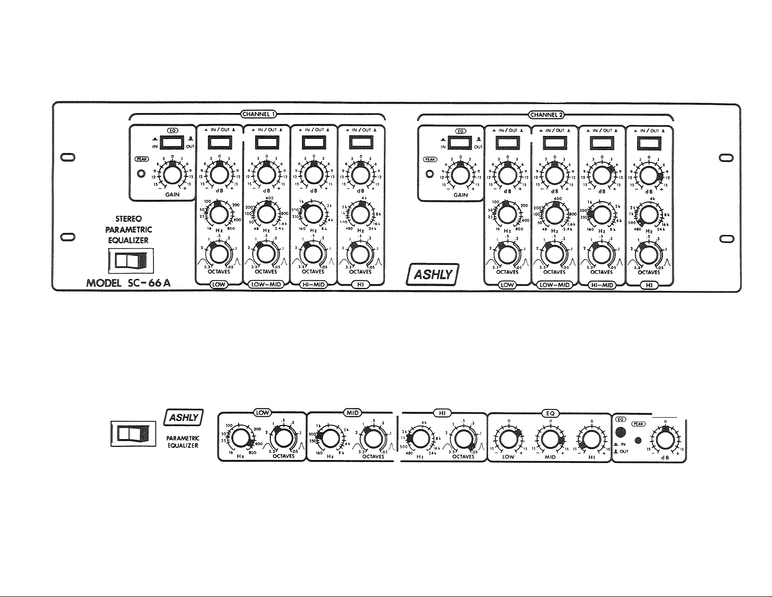
EXPLANATION OF PARAMETRIC EQ AND OUR CONTROLS
A Parametric Equalizer consists of several filter sections connected together
each capable of continuous and independent adjustment of: (1) AMPLITUDE,
(2) CENTER FREQUENCY, and (3) BANDWIDTH.
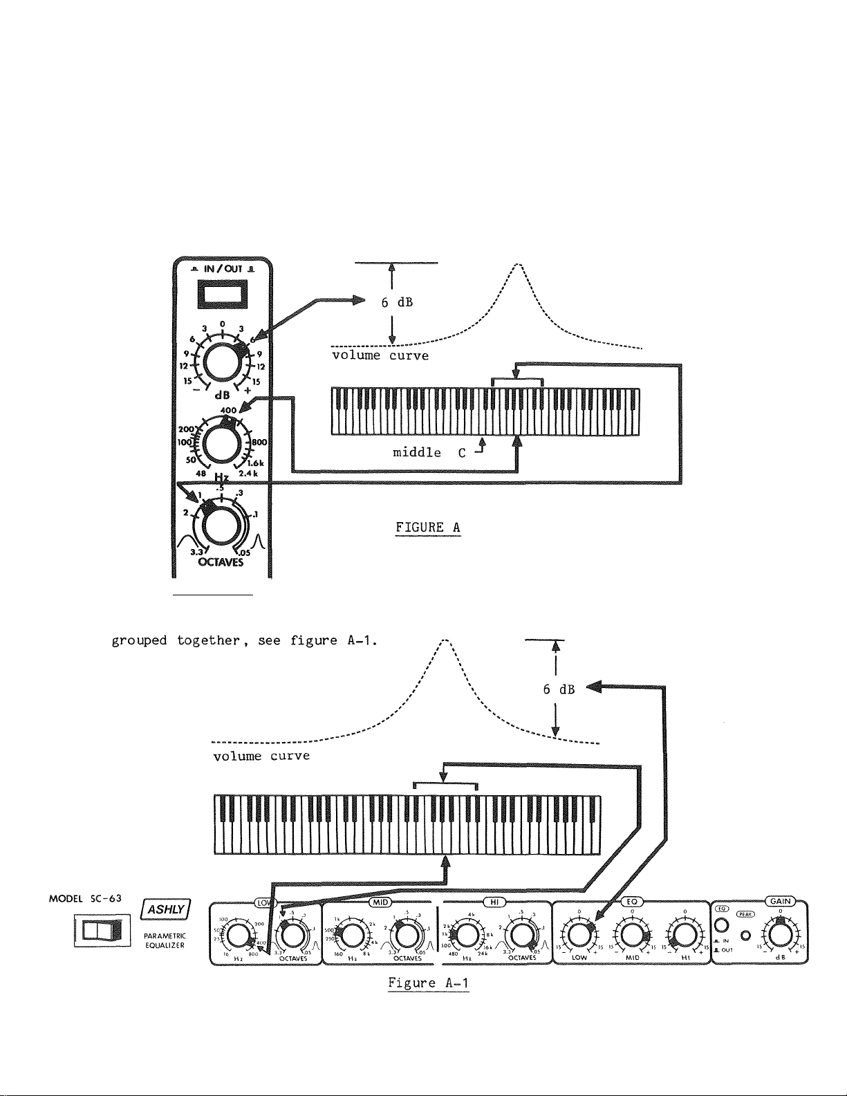
On the SC-66A, these controls are mounted vertically below individual in/out
switches, see figure A.
V LOW-MID K
On the SC-63t these controls are mounted horizontally with center frequency
and bandwidth controls grouped together and amplitude controls for three bands
Page 8

The (1) AMPLITUDE control (boost-cut) increases or decreases the volume of
notes selected by the center frequency and bandwidth controls. Maximum effect
is in the middle of those notes, (see volume curve in figures A and A-1)
The (2) CENTER FREQUENCY control selects the frequency to be most affected. A
clockwise turn moves the frequency up the keyboard, counter clockwise moves it
down •
The (3) BANDWIDTH control (sometimes refered to as "Q") selects the number of
notes to be affected (approximately 1 to 40). Figure B shows the frequency
response plot, above a piano keyboard of a typical octave graphic equalizer
with the 500 Hz slider boosted 12 dB.
12 dB
FIGURE B
Practically any frequency response setting of a graphic equalizer can be
duplicated with the SC-63 and SC-66A parametrics. To get the same response
plot as Figure B, simply set the (1) AMPLITUDE control at 12 dB, the
(2) CENTER FREQUENCY control at 500 Hz, and the (3) BANDWIDTH control at
1 octave (see figure C),
FIGURE C
The net result is: 500 Hz, or approximately the note "B", is boosted 12 dB
and the frequencies 1/2 octave above and below 500 Hz (1 octave bandwidth) are
Page 9

boosted 6 dB (half the maximum boost).
The advantage however, is not that we can duplicate what a graphic does, but
rather extend our frequency response plot to affect from nearly one note, to
forty notes (.05 to 3-3 octaves). See Figure D.
Other controls on the SC-66A (see front panel layout on page 3) include; power
switch, master equalization in/out switches, (NOTE: Switch winks to green
when depressed to "in" position. The switch winks to black in the out
position, sets the gain to unity and defeats all equalization in the channel)
individual equalization in/out switches, (NOTE: Switch winks to amber when
depressed to "in" position and affects only the band below it) gain control to
compensate for insertion gain or loss due to the equalization process ( + 15
dB), "peak" indicator light (one for each channel) monitors all potentTal
overload points in the channel and illuminates when the level at one of these
points reaches 6 dB below clipping.
FIGURE D
FEEDBACK SUPRESSION STEP BY STEP SETUP INSTRUCTIONS
1. Set all gain controls on your parametric to 0, and make sure your master
equalization in/out switch(s) are in the out position.
2. Set all equalization controls on your mixer to flat.
3. Make sure no microphone is pointing directly into a speaker.
4. If you have a limiter, adjust its threshold to hold feedback at a low
level.
5. Estimate the relative volume relationships between your vocal microphones
with individual channel sliders on your mixer, and use the master fader
on your mixer to bring the system into feedback. Make sure all other
channel faders are turned down. Do not let the feedback go uncontrolled
or you might damage your high frequency drivers!!
5. Match the first prom inant feedback note with an instrument or your ears,
and check the note against the frequency number on page 20, and reduce
system gain back to about 6 dB before feedback.
Select the most appropriate control band (LOW, MID, HI).
Page 10

8. Set your center frequency control to about an octave below the frequency
number you select.
9. Set the bandwidth control to full sharp (full clockwise).
10. Set the amplitude control of the chosen band to +6 dB.
11. Depress the master equalization in/out switch, and the appropriate band
in/out switch (SC-66A only), to the in position.
12. Very slowly rotate the center frequency control towards the selected
feedback frequency until feedback occurs. If feedback does not occur,
increase system gain and repeat step 11.
13. Repeat step 12 until you are sure you have the control centered on
exactly the desired frequency.
19. Move the amplitude control from +6 dB to -6 dB.
15. Increase the gain on your mixer until the next feedback sounds. If the
same feedback frequency occurs again, reset the amplitude control to -9
or more, as needed.
16. Repeat steps 6 thru 15 to notch out new feedback frequencies for maximum
gain before feedback.
NARROW BAND STEP BY STEP SETUP INSTRUCTIONS
1. Set all gain controls on your parametric to 0, and make sure your master
equalization in/out switch(s) are in the out position.
2. Set all equalization controls to flat.
3. Switch out all other equalization devices.
9. Estimate the problem frequency area (use the chart on page 20 for help).
5. Select the most appropriate control band (LOW, MID, HI).
6. Set your center frequency control to about an octave below the frequency
number selected.
7. Set the bandwidth control to .1 or sharper depending on what you are
trying to correct.
8. Set the amplitude control of the chosen band to +6 dB.
9. Depress the master equalization in/out switch, and the appropriate band
in/out switch (SC-66A only) to the in position.
10. Very slowly rotate the center frequency control towards the estimated
problem area until it is emphasized.
11. Repeat step 10 until you are sure you have the control centered on
exactly the desired frequency.
12. Re-adjust the amplitude control down from +6 to the (-) side until the
desired response is achieved. (Re-adjustment of the bandwidth control
may also be necessary)
Page 11

MEDIUM TO WIDE BAND STEP BY STEP SETUP INSTRUCTIONS
1. First, determine the frequency area of your problem,
2. Decide how wide a spread of frequencies are involved, (see chart on p. 20)
3. Determine whether your problem is an excess or a deficiency of a frequency
range.
4. Set the bandwidth control in accordance with #2 (usually from .5 to 3
octaves).
5. Set the amplitude control to accentuate your problem as determined in #3
either +5 dB or -5 dB,
6. Turn the center frequency control until your problem seems to be at its
worst (re-adjustment of the bandwidth control may be necessary).
7. Reset the amplitude control to correct your problem.
APPLICATION AND OPERATION FOR SOUND REINFORCEMENT
ITEM: Monitor System Feedback Control
Probably one of the most widely used functions of parametric equalizers is in
the control of feedback. The SC-63 and SC-66A's controls make it easy to
locate and notch out feedback frequencies. It is necessary however, to first
be able to understand the relationship between a given pitch and its
corresponding frequency number.
For this reason, the graph on page 20 showing a standard piano keyboard and
music score with the indicated frequencies should be refered to and memorized,
especially if the only test equipment you have are your ears.
The illustration below diagrams a typical monitor system hook-up. After the
addition of an SC-63 or SC-66A to your monitor system, it is possible to get
4 dB to 10 dB of additional gain before feedback. Use the narrow band step by
step setup instructions on page 8 as a guide to get you started. The actual
procedure you use may differ greatly after months of experimenting and use!
MONITOR
SEND
EQ
out in
POWER AMP
out
A TYPICAL MONITOR SYSTEM SIGNAL PATH
Page 12

ITEM;
Front System Speaker or Room Resonance Problems and Feedback Control
Once you become familiar with the controls on your parametric, you will find
it much easier to get the desired results from your system. Use the narrow
band step by step setup instructions on page 8 as a guide to get you started,
NOTE; The maximum volume of your monitors and front system before feedback
should be determined if the steps on page 8 are followed. If you are still
not satisfied, here are some suggestions that might help:
Place all main system speakers and monitors such that they do not "see"
any microphones that are to be fed to them.
Keep all guitar and keyboard stage amps away from vocal microphones.
Keep your stage volume as low as possible so your sound person has
something to work with out front.
Work vocal microphones as close as possible.
When you can't hear yourself, have everyone else turn down rather than
you turning up. You have already determined the maximum volume of your
PA system, and if your fellow band members feel they can't turn down any
more, collect donations to pay for upgrading your present system, ie;
separate mixes for monitor speakers, more directional microphones, better
speakers, etc.
ITEM; Shaping The Overall Sound Of Your System To Improve Response
Many PA systems use several bands of graphic equalization for frequency
response adjustment. For many situations, one band of parametric equalization
could achieve better results.
Say, for example, that the response of a high powered horn and driver that you
are using has a noticeable 3 dB rise in the frequency area from around 1,100
Hz to 3.500 Hz. If you attempted to correct your problem with a 1/3 octave
graphic equalizer, you would need to move five separate controls. Visually,
what looks like a nice smooth curve on the front controls of a graphic, turns
out to be a very bumpy curve as illustrated below.
This occurs because each control has a fixed bandwidth. Combinations of
filters can not generate the smooth curve of one variable filter.
Using one band of parametric with the frequency control set in the middle of
the problem area (approx. 2,200 Hz), the bandwidth control at 2 octaves, and
the amplitude control set at -3 dB, you get a frequency response plot that
will more accurately correct the problem.
1 0
Page 13

Broad bandwidth problems are much easier to solve with an Ashly parametric
equalizer. On a graphic you can be trying to manipulate as many as 10 to 15
controls to find the right response. In fact, in many instances a graphic
equalizer can't correct the problem anyway simply by the nature of its design.
Use the medium to wide band step by step setup instructions on page 9 to
assist you in correcting your problem. Remember to give careful consideration
determining your problem, rather than trying to find a problem that may not
exist!
OPERATION FOR USE AS AN INSTRUMENT TONE CONTROL
Graphic type equalizers, while initially easier to operate, can not be as
accurate as the SC-63 and SC-66A parametric equalizers. A parametric
equalizer gives unrestricted control of all the notes your instrument can
produce. The chart on page 20 shows the relationship between the notes you
play and the corresponding frequency number. There should be very little
guess work in deciding how you want to equalize your instrument once this
chart is used. Most musicians are already familiar with the terminology A =
490 Hz. By learning the numbers of other notes, you take the guess work out of
knowing where to set the controls on your parametric.
A common problem with many instruments is uneven response from low to high
notes. On string instruments you usually have one or more strings that are
not as loud, when picked or bowed, as the other strings. On wind instruments;
mouthpieces, reeds, and even weather changes can alter response. Most
keyboard players really have response problems!!
A general rule to follow is; listen carefully to your instrument and
determine what the response problems are. Try first, to correct them with
conventional means! Use equalization as a last resort, unless you are trying
to achieve special effects. The less equalization you use, the easier it will
be to get the "right" sound every time.
Use the narrow and medium to wide band setup suggestions on pages 8 & 9 to get
started.
Patch your equalizer into your system after the pre-amplification stage. Most
instrument pick-ups and direct outputs have too low a level to properly drive
the input of the SC-53 or SC-66A. An effects loop will work well, or if you
are feeding a mixer, use a direct in/out patch point on the channel.
APPLICATION AND OPERATION FOR RECORDING
The SC-63 and SC-66A can be used to augment or replace existing equalizers,
and compensate for system inadequacies. Experimentation with the SC-63 and
SC-66A will yield better results if the set up suggestions, trouble shooting
information and reference graph information in this manual is read.
ITEM: Critical Monitor Speaker Response Adjustment
Most control room monitor speakers have fairly smooth frequency response.
However, room acoustics can radically alter the freqency response you hear.
By using an SC-63 or SC-66A patched in before the monitor speakers amplifier
(or electronic crossover, if applies) you can compensate for room resonances
or dead spots. For exact results, some type of realtime analyzer, or scope
with a frequency sweep should be used.
1 1
Page 14

ITEM: Individual Input Channel Equalization
Most mixing consoles offer some type of equalization for each channel. Unless
it is a full parametric type, it can not offer the complete flexability of the
SC-63 or SC-66A. If your mixer does have a parametric type equalization
section, the SC-63 or SC-66A will add more flexability with a minimum of
ex pen se.
Many mixers have individual channel direct in/out patch points that will
interface with the SC-63 and SC-66A. If yours does not, a simple modification
can usually be done by a qualified technician.
Use the SC-63 or SC-66A to give instruments, playing in the same range,
individuality. (ie; boost the fundamental frequencies of one instrument and
the harmonics of the other) By becoming familiar with the chart on page 20,
guess work will be minimized.
Use the setup suggestions on pages 7 - 9 as a general guide.
ITEM: Obtaining Better Results From Reverb And Effects Units
By patching an SC-63 or SC-66A right before a reverb or effects unit, you can
minimize high and low frequency loss. Boost those ranges before they go into
a reverb or effects unit to compensate for losses. Isolating frequency ranges
that go into an effects unit can also make an effect more pronounced.
APPLICATION AND OPERATION FOR BROADCASTING
ITEM: Announcer Voice Enhancement
Only full parametric type equalization as offered by the SC-63 and SC-66A can
modify voice frequencies accurately.
Patch in an SC-63 or SC-66A after the voice microphone has been pre-amplified.
Determine the frequency range of the announcers voice (100 Hz to 500 Hz
fundamental, 800 Hz to 2,500 Hz presence area). Cut frequencies above and
below, and boost fundamentals for warmth, or boost the presence area for
definition. Experiment with bandwidth settings to match the exact range of
the announcers voice.
Sibilance problems (8,000 to 12,000 Hz range) can be notched out without
affecting the overall sound. Use the step by step instructions on page 8 as a
guide.
ITEM;
Record Wear Equalization Correction
After several plays, a record loses its high frequency response. The SC-63
and SC-66A can be tuned to bring back some of that lost high frequency without
altering frequencies that are still ok. Use the setup suggestions on page 9
as a guide.
APPLICATION AND OPERATION FOR DISCOTHEQUES
Graphic type equalizers, while initially easier to operate, can not offer the
unrestricted tone control of the SC-63 and SC-66A. Old time radio effects,
bass guitar emphasis, frequency selected voice over effects, and modified
speaker response curve settings represent only a few of the many
1 2
Page 15

possibilities. Experimentation with the SC-63 and SC-66A should only be done
after you are completely familiar with all the controls.
Note; The SC-63 and SC-66A offer complete equalization control, and this same
complete control in the wrong hands can destroy a speaker system.
ITEM: Placement Of An SC-63 Or SC-66A In A Discotheque System
The SC-63 or SC-66A must always be patched into a system before the speaker
amplification stage, and after the pre-amplification stage of a mixer. (an
effects loop or somewhere between your mixer and amplifier will work well)
Use only shielded cable for connections to and from the SC-63 and SC-65A.
APPLICATION AND OPERATION FOR MOTION PICTURE SOUND AND TV
The variability of every equalization parameter offered by the SC-63 and SC66A make its selection for use in this field an ex allent choice. State of
the art technology, internal modular design and external rugged construction
make the SC-63 and SC-66A reliable and easily serviceable.
ITEM:
Determine if unwanted sounds cover a very narrow range or a medium to wide
range, and use the appropriate set up suggestions on pages 8 and 9.
ITEM: Voice Enhancement
See: Application And Operation For Broadcasting on page 12.
Refer to other operating suggestions on pages 9-13.
Removal Of Unwanted Sounds
13
Page 16

CIRCUIT DESCRIPTION
The heart (and primary expense) of the SC-66A and SC-63 is a unique bandpass
filter circuit. Basically a "state-variable" type, this filter is trimmed and
optimized to provide excellent transient response and a wide-range bandwidth
adjustment. Each filter in the SC-66A and SC-63 can be tuned over a 50:1
frequency range (about 5 1/2 octaves) and a 70:1 bandwidth range with no more
than a 2 dB amplitude error at center frequency. At its sharpest setting, the
filter has a "Q" of about 35 and generates a response curve with 3 dB points
only 1/20 octave apart, making feedback control possible with no audible side
effects. The filters are manufactured as individual, plug-in units to make
servicing easy.
Each filter is placed in the feedback loop of a summing amplifier to produce
the desired frequency response. Since a separate summing amplifier is used
for each band, no interaction between bands occurs.
Page 17

DEFINITION OF TERMS AS USED IN THIS MANUAL
ACTIVE
Electronic circuits which use devices such as transistors and integrated
circuits, and which are capable of voltage and power gain as well as
loss. Circuits using only resistors, capacitors, transformers, etc., are
referred to as passive.
AMPLITUDE
The voltage level of a signal. May be measured in volts or decibels.
Generally corresponds to the volume or intensity of an audio signal.
BALANCED
A 3-wire circuit arrangement in which two conductors are designated as
signal lines (+ and -), and the third is a shield and chassis ground. The
signal lines are of opposite polarity at any given moment, and are of
equal potential with respect to ground. Balanced input amplifiers are
used on all Ashly SC series products to improve hum and noise rejection.
Jumpering signal minus (-) to ground provides an unbalanced input.
CENTER FREQUENCY
The frequency (or pitch) at which a filter is most effective. In a
parametric equalizer, it refers to the frequency where a particular
boost/cut control has maximum effect.
dB
A unit by which audio levels can be COMPARED. Often thoroughly
misunderstood are the concepts that decibels represent the level of a
signal compared to some reference level (15 dB cut means a certain level
less than a previous level
---
the absolute level of the signal need not
be known), and that decibels are a logarithmic unit.
Some handy numbers to remember when dealing with decibels:
dB
+3
+6
+ 10
+20 dB = 10X Amplitude,
= Double Power
dB
= Double Amplitude, Quadruple Power
dB
= 10X Power
100X Power
dBm
A unit
m illiwatt
of measurement in decibels where 0 dBm = a power level of 1
into a 600 ohm load. Originally
defined by the
company to measure line levels.
dBV
Decibel Volts, an update of the dBm definition where 0 dBV = the same
voltage level as 0 dBm, but with no regard to power or impedance. 0 dBV =
0.778 Volts. This unit is much more appropriate for modern audio
equipment with high impedance inputs and low impedance outputs.
DISTORTION
Generally refers to ANY modification of an audio signal which produces
new frequencies which were not in the original. Examples are harmonic
distortion, where a circuit adds overtones to a fundamental signal, and
intermodulation or IM distortion, where two frequencies beat together to
produce sum and difference frequencies.
FEEDBACK
Generally refers to any process where an output is in some form routed
back to an input to establish a loop. Negative feedback tends to be be
self stabilizing, while positive feedback causes instability.
telephone
15
Page 18

FILTER
A circuit designed to pass some frequencies, but not others. There are
three general categories of filters: High-pass, band-pass, and low-pass.
The high-pass filter passes frequencies above a certain lim't, the low-
pass passes frequencies below a limit, and the band-pass passes one group
of frequencies without passing those above or below. Our equalizer uses
band-pass filters, crossovers use high and low-pass filters.
FREQUENCY
The repetition rate of a waveform. Frequency is measured in Hertz. One
cycle per second (cps) is one Hertz (Hz). The higher a note on a musical
scale, the higher its frequency.
FREQUENCY RESPONSE
Refers to relative gain and loss at various frequencies across the audio
band. May be illustrated by a graph called a frequency response plot,
usually graphing decibels vs. Hertz or octaves.
HERTZ (Hz)
The unit of frequency measurement,
(Formerly called Cycles-per-Second;
this explains it perfectly)
HEADROOM
Refers to the increase in level above normal operating level that can be
obtained without clipping. Usually expressed in dB.
IMPEDANCE
Essentially the AC equivalent of resistance. It describes the drive
capability of an output, or the amount of drive required for an input at
any given signal level.
KHz
Kilohertz. 1,000 Hertz.
LEVEL
The magnitude of a signal, expressed in decibels or volts.
LINE LEVEL
Meaning "somewhere around OdBV" as opposed to MIC level of around -40dBV.
OCTAVE
A logarithmic unit to compare frequencies,
+1 Octave means double
frequency, -1 Octave means half frequency.
OHM
The unit of electrical resistance or impedance,
PHASE
Describes how well two signals are in step. In-phase means that positive
and negative peaks in two signals occur together, while out-of-phase
means they do not occur together. Variations in signal timing as well as
polarity can make two signals in or out of phase, or anywhere in between.
Phase is usually measured in degrees where 0 degrees is in-phase, 180
degrees is out-of-phase, and 90 degrees is in between (sometimes called
quadrature) .
PREAMPLIFIER
The first stage of amplification,
designed to boost very low level
signals to line level.
A measurement describing the sharpness or broadness of a filter.
16
Page 19

SHELVING
Describes an equalization action where all frequencies above or below a
particular frequency are boost or cut.
TRANSIENT
A sudden burst of energy in an audio signal, such as a breath blast in a
microphone, the sound of a snare drum, or a deep scratch in a record.
Transients frequently reach peak levels of 10 to 30 dB above standard
operating level, and may cause distortion or even damage to equipment.
UNITY GAIN
Output level Input level.
WIRING, PHONE PLUG AND XLR
A stereo phone plug is wired + to the tip,
the sleeve. For a mono phone plug, combine
to the sleeve.
- to the ring, and shield to
and shield, and connect both
An XLR (3 Pin) connector is wired
pin 1.
Mono Phone Plug:
(for unbalanced
inputs and outputs)
Stereo Phone Plug ;
(for balanced in
puts and outputs)
XLR Type Connector:
(Male Shown)
to pin 3, - to pin 2, and shield to
Sleeve
■Tip
Sleeve
Ring
\
.Tip
17
Page 20

TROUBLE SHOOTING TIPS
NO OUTPUT
Check AC power - is the pilot light on? Check in/out connections, are
they reversed? Are you sure you have an input signal?
EQ CONTROLS DO NOT DO ANYTHING
Is the master eq in/out switch in? Maybe the bandwidth setting is too
sharp to produce an audible change. Do not expect the center frequency
and bandwidth controls to have an effect if the amplitude control is set
at "0", or if the in/out switches are switched out,
PEAK LIGHT FLASHES OR STAYS ON ALL THE TIME
If the peak light flashes, the signal level to the equalizer is too high.
Turn down the gain. If it is on all the time, disconnect the input and
output cables. If it is still on, the unit must be returned for service.
DISTORTED SOUND
This will only be caused by too much signal (which will show on the
"peak" light. If the light is not flashing, there is an overload
somewhere else in the chain. Adjust the relative gain of each component
in your chain to keep everything at a comfortable level.
EXCESSIVE HUM OR NOISE
Hum will usually be caused by a "ground loop" between components. Try
using the suggested balanced input and output hook-ups if the other
pieces of equipment used in conjunction with your equalizer have balanced
inputs and outputs. Noise can be caused by insufficient drive signal.
Make sure you are sending a nominal 0 dBV line level signal to the
equalizer.
NOTE:
UN-SHIELDED CABLES, IMPROPERLY WIRED CONNECTIONS, AND CABLE WITH BROKEN
STRANDS (SHORTS ETC.) ARE THE MOST COMMON PROBLEMS.
WHEN IN DOUBT, GET IN TOUCH WITH YOUR ASHLY DEALER, OR CALL THE FACTORY
DIRECT - (800)828-6308. In New York State dial (716)544-5191.
Page 21

SPECIFICATIONS
sc=63
CONTROLS
Master Gain
Master Defeat Switch
Bandwidth
INPUT IMPEDANCE
SC-66A
CONTROLS
Master Gain
Master Defeat Switch
Defeat Switch
Frequency
INPUT IMPEDANCE
Master
Per Band
Amplitude
Frequency
(iow)
(mid)
(high)
Master
Per Band
Amplitude
(low)
(low-mid)
(hi-mid)
(high)
Bandwidth
t15dB
±15dB
16HZ-B00HZ
160Hz-8kHz
480Hz-24kHz
3 1/3 oct -1/20 oct
10k il active balanced
bridging
t15dB
±15 dB
16HZ-800HZ
48Hz-2.4kHz
160Hz-8kHz
480Hz-24kHz
3 1/3 oct -1/20 oct
10k il active balanced
bridging
OUTPUT IMPEDANCE
MAX. IN-OUT LEVEL
FREQUENCY RESPONSE
DISTORTION
HUM AND NOISE
POWER
SIZE
SHIPPING WEIGHT
OUTPUT IMPEDANCE
MAX. IN-OUT LEVEL
FREQUENCY RESPONSE
DISTORTION
HUM AND NOISE
POWER
SIZE
SHIPPING WEIGHT
50 Q , term with 600 il
or more
+20dBm (+5 dBm at max.
boost, full sharp)
+.5dB 20Hz-20kHz
< .5% THD, +10 dBV
20Hz-20kHz
■87dBV (eq in) -95dBV
(eq out)
120 VAC, 50-60HZ, 5W
19"L X 1 3/4"H X 6"D
8 lbs.
soil .term with 600il
or more
+20dBm (+5 dBm at max.
boost, full sharp)
±.5dB 20Hz-20kHz
< .05% THD, +10 dBV
20Hz-MkHz
-87dBV (eq in) -95dBV
(eq out)
120 VAC. 50-60HZ, 5W
19"L X 5 1/4"H X 6"D
12 lbs.
19
Page 22

va
ra
A
------------------------------------------------------------------------------------------------
—————
=C^F=
1^^
i
GO
..........
- - -
.——.............
w
6
J
GO
«;
CQ
.......—......
1 I:—’. . . . . . . . . . . . . . . . . . . . . :::
—-—
-------------------
K
w
u
s
o
-------------—^—-—
. . . . . . . . . . . . . . . . . . . . .. . .. . .. . .. . . .
HARMONICS
..................—......
.
.
n T
o <NJ U3
(TO<nLr)>-.u^{r) CMt^cOOm
J--3-tOU3U3r^ COcOCr>'-tc4
Actual frequency numbers (Hz) may vary from the above chart.
n
n m
—1
iO^'X>Or».C'4J-OCncvlO^J'CO OCOJ-OCO(X)l£>oa)COO UDU5040CM<Xi
i£»r^cncNjt^<T>m ^cDcMco t^cTicocoa3j-r^ <NCTi'-D«xi j-<t> m
'M«-tr-4C40vicvic^ro coco ^ j-mm u>u3t^ cocnor-«foroif>i>- (T>o<r>ix)r^ —<
'-iCMCNlCsJCNjfO
CM CM
lO CTi
 Loading...