

COMPR
The Ashly Audio SC-50 Peak Limiter Compressor
is used to place a "ceiling" on the peak levei of
program material. When peaks exceed this
ceiling, gain is reduced to keep peaks within
specified limits, The amount of reduction, how
fast reduction takes place, and the speed at
which levels are returned to normal are all
precise and independent adjustments. This
makes the SC-50 extremely useful for loud
speaker protection, broadcast limiting or com
pression, tape to disc transfer, special effects,
vocal level control and musical instrument
sustain.
FEATURES:
• Extremely low noise ond distortion
• Detector patch point for frequency
selective limiting
• Stereo tie patch point for accurote stereo
or quad tracking when multiple units are
used
• Double time constant release action
• Accurate and specific control calibrations
• Inputs and outputs that can be used
balanced or unbalanced
• Rugged 16 gauge steel chassis
• In/out bypass switching
® o o ©
CAWTtON: TO »HfVENT n.ECT«C ShOM
OOMOTOnN NO UKR Unv)CAai.l
' PART« MSIOC R|aR SCRViCMa TO
OlMlincO TfOMOAN CONNECT TO
OnOUMOCOOUJlET lOMEYEKTr««
OR EVCCTfDC &NOCK 00 NOT CXPOM
r>«S AmWkNCE TO MM OR UOiSTURC
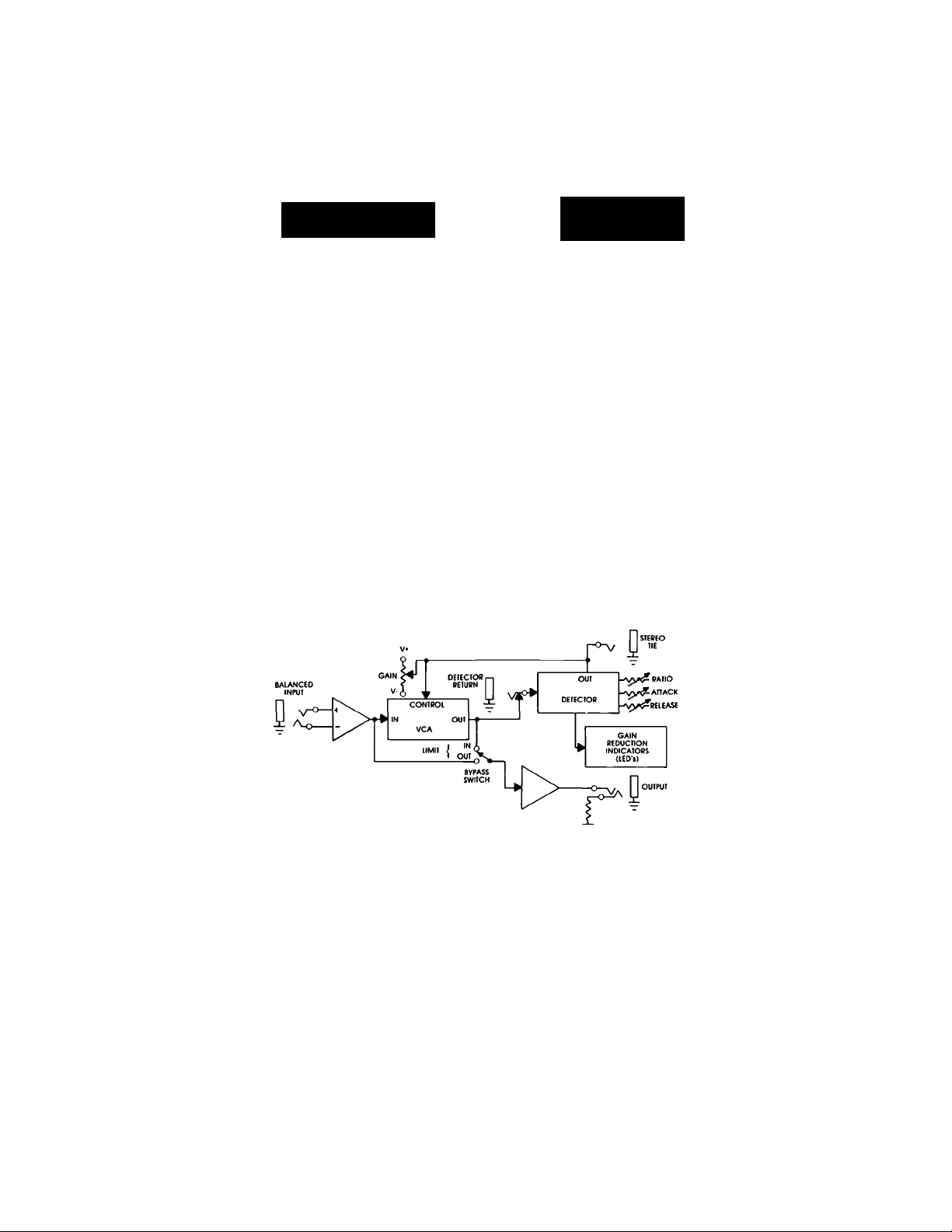
The two important components of the SC-50 ore the
VCA (Voltage Controlled Amplifier) and the Detec
tor. The Ashly SC-50 VCA is an all NPN current ratio
multiplier circuit using integrated "supermatch"
transistor pairs. It has low noise (-90 dBV), low
distortion (.05%), excellent response time and track
ing and does not suffer from thermal drift. It is a little
complex - there are 5 supporting op-amps involved
— but today's low-cost, high-quality op-amps make
this feasible. The circuit is consistent in mass produc
tion with no trimming or hand selection of transistors
necessary.
On the surface it would seem that the VCA is more
critical than the detector since audio passes through
the VCA and the detector only provides it with a
control voltage. However, experience showed us
that both are crucial to the overall sound. The
detector must constantly adjust the gain of the
audio path in a manner which keeps the level under
control while sounding acceptable to the listener.
This constantly changing gain is a DYNAMIC action,
and conventional audio measurements like noise
and distortion checks are static (constant level). This
led us to use a purely subjective approach in the
design of the detector; we did a lot of listening to
determine what sounded good and what didn't. As
a result of this research we designed the detector to
let the attack and release times speed up as more
and more limiting occurs (the compression ratio
also increases), and a double release time constant
was incorporated to minimize "pumping" and
"breathing".
CONTROLS
defeat switch
gain
ratio
attack time
release time
INPUT IMPEDANCE
OUTPUT IMPEDANCE
DETECTOR PATCH
POINT
^30dB
2:1 -cx>
200uS. - 20 mS.
100 mS - 2S
10KU balanced bridging
50 il term, with 600 Si
or more
allows the connection ot an
equalizer In the detector
loop to produce frequency
selective limiting.
SPECIFICATIONS:
MAX. IN-OUT LEVEL
FREQUENCY
RESPONSE
DISTORTION
HUM AND NOISE
POWER
SHIPPING WEIGHT
SIZE
■ 20dBm
^.5dB 20Hz-20kHZ
< .05% THD, OdBV,
20Hz-20kHz, no limiting
< .2% ' IBdBV worst case.
-90dBV, unity gain
120 VAC, 50-60HZ, 5W
19"L X 1 3/4"H X 6"D
8 lbs.
 Loading...