

Page 1
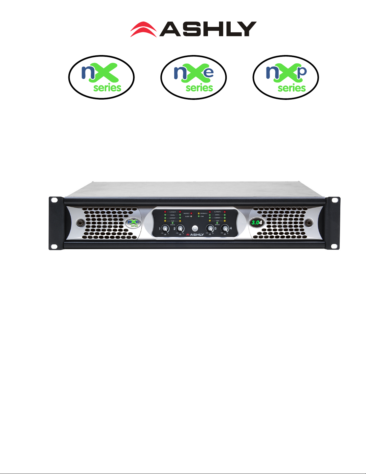
Operating Manual
Multi-Mode Power Ampliers
3,000W, 1,500W, 800W, and 400W Per Channel
Four and Two Channel Models
nX Base Series
nX3.04, nX3.02, nX1.54, nX1.52
,
nX8004, nX8002, nX4004, nX4002
nXe Ethernet Series*
nXe3.04, nXe3.02, nXe1.54, nXe1.52, nXe8004, nXe8002, nXe4004, nXe4002
nXp Ethernet+DSP Series*
nXp3.04, nXp3.02, nXp1.54, nXp1.52
*Protea software is available for free download on the Ashly website.
Ashly no longer includes a software CD-ROM with new units.
,
nXp8004, nXp8002, nXp4004, nXp4002
ASHLY AUDIO INC.
847 Holt Road Webster, NY 14580-9103 Phone: (585) 872-0010
Toll-Free: (800) 828-6308 Fax: (585) 872-0739 ashly.com
All Trademarks referred to herein are the property of their respective owners.
2017-2018 Ashly Audio, Inc. All rights reserved worldwide.
Page 2
Operating Manual - nX, nXe, and nXp Power Ampliers
Important Safety Instructions
Consignes de sécurité à lire attentivement
The lightning ash with arrowhead symbol, within an equilateral triangle,
is intended to alert the user to the presence of uninsulated "dangerous
voltage" within the product's enclosure that may be of sufcient magnitude
to constitute a risk of electric shock to persons. The exclamation point
within an equilateral triangle is intended to alert the user to the presence
of important operating and maintenance instructions in the literature accompanying the device.
1. Read these instructions.
2. Keep these instructions.
3. Heed all warnings.
4. Follow all instructions.
5. To reduce the risk of re or electric shock, do not expose this
apparatus to rain or moisture.
6. Do not use this apparatus near water.
7. Clean only with dry cloth.
8. Do not block any ventilation openings. Install in accordance with
the manufacturer’s instructions.
9. Do not install near any heat sources such as radiators, heat
registers, stoves, or other apparatus.
10. Do not defeat the safety purpose of the polarized or groundingtype plug. A polarized plug has two blades with one wider than the
other. A grounding type plug has two blades and a third grounding prong. The wide blade or the third prong are provided for your
safety. If the provided plug does not t into your outlet, consult an
electrician for replacement of the obsolete outlet.
11. Protect the power cord from being walked on or pinched par-
ticularly at plugs, convenience receptacles, and the point where they
exit from the apparatus.
12. Only use attachments/accessories specied by the manufac-
turer.
13. Use only with the cart, stand, tripod, bracket, or table specied
by the manufacturer, or sold with the apparatus. When a cart is
used, use caution when moving the cart/apparatus combination to
avoid injury from tip-over.
14. Unplug this apparatus during lightning storms or when unused
for long periods of time.
15. Refer all servicing to qualied service personnel. Servicing is
required when the apparatus has been damaged in any way, such as
power-supply cord or plug is damaged, liquid has been spilled or objects have fallen into the apparatus, the apparatus has been exposed
to rain or moisture, does not operate normally, or has been dropped.
Le symbole de la èche dans un triangle équilateral symbolisant la foudre
est prévu pour sensibiliser l’utilisateur à la présence de tension de voltage
non isolée à l’intérieur de l’appareil. Elle pourrait constituer un danger de
risque de décharge électrique pour les utilisateurs. Le point d’exclamation
dans le triangle équilatérale alerte l’utilisateur de la présence de consignes
qu’il doit d’abord consulter avant d’utiliser l’appareil.
1. Lisez ces instructions.
2. Conservez ces instructions.
3. Observez les avertissements.
4. Suivez ces instructions.
5. Pour réduire le risque de feu ou la décharge électrique, ne pas
exposer cet appareil pour pleuvoir ou l'humidité.
6. Ne pas utiliser l’appareil près de l’eau.
7. Le nettoyer à l’aide d’un tissus sec.
8. Ne pas bloquer les ouvertures de ventilation, installer selon les
consignes du fabricant.
9. Eloigner des sources de chaleur tel: radiateurs, fourneaux ou
autres appareils qui produisent de la chaleur.
10. Ne pas modier ou amputer le système de la mise à terre. Une
prise avec mise à terre comprend deux lames dont une plus large
ainsi qu’une mise à terre: ne pas la couper ou la modier. Si la prise
murale n’accepte pas la che, consulter un électricien pour qu’il
remplace la prise désuète.
11. Protéger le cordon de secteur contre tous bris ou pincement qui
pourraient l’endommager, soit à la che murale ou à l’appareil.
12. N’employer que les accessoires recommandés par le fabricant.
13. N’utiliser qu’avec les systèmes de xation,chariots, trépied ou
autres, approuvés par le fabricant ou vendus avec l’appareil.
14. Débrancher l’appareil lors des orages électriques ou si inutilisé
pendant une longue période de temps.
15. Un entretient effectué par un centre de service accrédité est
exigé si l’appareil a été endommagé de quelque façon: si il a été
exposé à la pluie,, l’humidité ou s’il ne fonctionne pas normalement
ou qu’il a été échappé.
2
WARNING: THIS APPARATUS MUST BE EARTHED
Page 3
Operating Manual - nX, nXe, and nXp Power Ampliers
FCC Compliance
This device complies with part 15 of the FCC Rules. Operation is subject to the following two conditions:
1. This device may not cause harmful interference
2. This device must accept any interference received, including interference that may cause undesired operation
Note: This equipment has been tested and found to comply with the limits for a Class B digital device, pursuant to part 15 of the FCC Rules. These limits are designed
to provide reasonable protection against harmful interference in both a commercial and residential installation. This equipment generates, uses and can radiate
radio frequency energy and, if not installed and used in accordance with the instructions, may cause harmful interference to radio communications. However,
there is no guarantee that interference will not occur in a particular installation. If this equipment does cause harmful interference to radio or television reception,
which can be determined by turning the equipment off and on, the user is encouraged to try to correct the interference by one or more of the following measures:
- Reorient or relocate the receiving antenna.
- Increase the separation between the equipment and receiver.
- Connect the equipment into an outlet on a circuit different from that to which the receiver is connected.
- Consult the dealer or an experienced radio/TV technician for help..
Warning:
This device is capable of producing output which can create very high sound pressure levels (SPL) from loudspeakers, which over
time can lead to hearing loss.
The US Occupational Safety and Health Administration (OSHA) has published guidelines for protection against the effects of
occupational noise exposure.
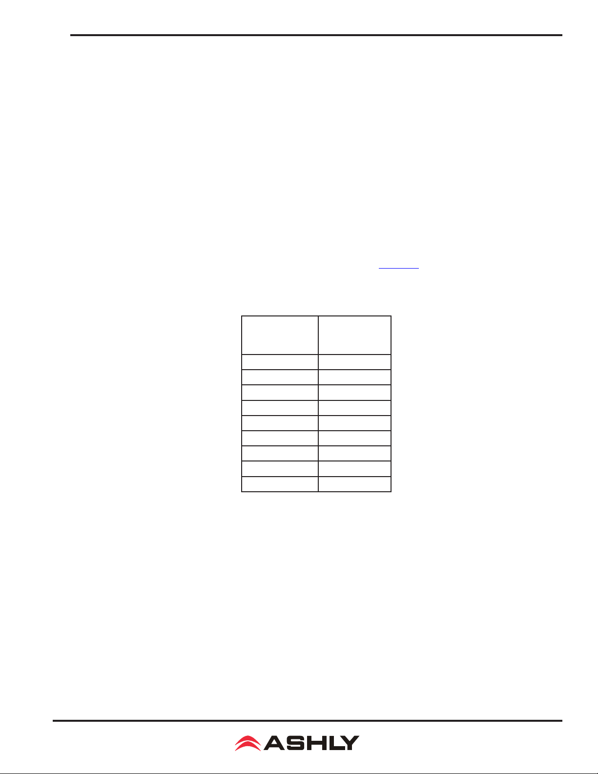
Please refer to the following OSHA table for safe noise exposure limits, and always take precautions to avoid excessive exposure
to loud environments.
Sound level
(dBA, slow
response)
Maximum Dura-
tion
(Hours per day)
90 8
92 6
95 4
97 3
100 2
102 1 1/2
105 1
110 1/2
115 1/4 or less
Unpacking
As a part of our system of quality control, every Ashly product is carefully inspected before leaving the factory to ensure awless appearance.
After unpacking, please inspect for any physical damage. Save the shipping carton and all packing materials, as they were carefully designed
to reduce to a minimum the possibility of transportation damage should the unit again require packing and shipping. In the event that damage
has occurred, immediately notify your dealer so that a written claim to cover the damages can be initiated.
The right to any claim against a public carrier can be forfeited if the carrier is not notied promptly and if the shipping carton and packing
materials are not available for inspection by the carrier. Save all packing materials until the claim has been settled.
About Ashly
Ashly Audio was founded in 1974 by a group of recording engineers, concert sound professionals, and electronics designers. The rst products were
elaborate custom consoles for friends and associates, but business quickly spread to new clients and the business grew. The philosophy we established
from the very beginning holds true today: to offer only the highest quality audio tools at an affordable cost to the professional user – ensuring reli-
ability and long life. Years later, Ashly remains committed to these principles.
Ashly’s exclusive Five Year, Worry- Free Warranty remains one of the most generous policies available on any commercial- grade product.
The warranty covers every product with the Ashly brand name, and is offered at no extra cost to you.
Please read this entire manual to fully understand the features and capabilities of this product.
3
Page 4

Operating Manual - nX, nXe, and nXp Power Ampliers
Table of Contents
1 Introduction . . . . . . . . . . . . . . . . . . . . . 6
1.1 Amplier Series. . . . . . . . . . . . . . . . . .6
2 nX Installation Requirements . . . . . . . 7
2.1 AC Mains Voltage, Power, and Current. . 7
2.2 Input Signal Wiring. . . . . . . . . . . . . . . 8
2.3 Output Speaker Wiring . . . . . . . . . . . . 8
2.4 Remote Control Wiring . . . . . . . . . . . . 8
2.5 AUX Output Wiring . . . . . . . . . . . . . . .9
2.6 Mechanical. . . . . . . . . . . . . . . . . . . . . 9
2.7 Cooling . . . . . . . . . . . . . . . . . . . . . . . 9
3 nX Amplier Protection . . . . . . . . . . . 10
4 Front Panel Features (all models). . . 10
4.1 Mounting Holes . . . . . . . . . . . . . . . . . 10
4.2 Air Inow Vents. . . . . . . . . . . . . . . . . 10
4.3 Factory Reset/Sleep Mode Switch . . . . 10
4.4 Channel Attenuators . . . . . . . . . . . . . 11
4.5 Channel LED Indicators . . . . . . . . . . . 11
4.6 Amplier Status LEDs . . . . . . . . . . . . 11
4.7 Power Switch/LED . . . . . . . . . . . . . . . 11
4.8 Series and Model Labels . . . . . . . . . . . 11
5 Rear Panel Features (nX Series) . . . . 12
5.1 Channel Conguration DIP Switch . . . . 12
5.2 Euroblock Input Jack . . . . . . . . . . . . . 12
5.3 Remote DC Level Control . . . . . . . . . . 12
5.4 Combo Input Jack . . . . . . . . . . . . . . . 12
5.5 Bridge Mode Switch . . . . . . . . . . . . . . 12
5.6 SpeakON® Output Jacks . . . . . . . . . . . 12
5.7 PowerCON® AC Mains Connector . . . . . 12
5.8 Serial Number Sticker . . . . . . . . . . . . 12
6 Rear Panel Features (nXe Series) . . . 13
6.1 Ethernet Port . . . . . . . . . . . . . . . . . . 13
6.2 Network Audio Module Option . . . . . . . 13
6.3 Standby Contact Closure . . . . . . . . . . 13
6.4 Fault Logic Outputs . . . . . . . . . . . . . . 13
6.5 Preset Recall Contact Closure . . . . . . . 13
6.6 Serial Data Connector . . . . . . . . . . . . 13
6.7 Aux Outputs . . . . . . . . . . . . . . . . . . . 13
6.8 AES3 Digital Audio I/O Option. . . . . . . 13
7 Rear Panel Features (nXp Series) . . . 14
7.1 Installed DSP . . . . . . . . . . . . . . . . . . 14
8 Ethernet Communications . . . . . . . 14
8.1 IP Address . . . . . . . . . . . . . . . . . . . . 14
8.2 Firewalls. . . . . . . . . . . . . . . . . . . . . . 14
8.3 Wi-Fi and LAN . . . . . . . . . . . . . . . . . . 14
8.4 Connecting Devices . . . . . . . . . . . . . . 14
*NOTE: Sections 9-13 (p15-51)
are NOT included in the printed
manual shipped with nX ampliers.
The complete owner's manual is available as a PDF le on the Ashly Website. For best results when viewing
and navigating the PDF le, enable
the PDF Bookmarks.
9 Proteane Software . . . . . . . . . . . . . . . . 15
9.1 Installing and Using the Software . . . . 15
9.1a Ashly Network Tree. . . . . . . . . . . . 15
9.1b Ashly Project Canvas . . . . . . . . . . 15
9.1c File Menu. . . . . . . . . . . . . . . . . . . 16
9.1d Network Menu . . . . . . . . . . . . . . . 16
9.1e Project Menu . . . . . . . . . . . . . . . . 16
9.1f Add Item Menu . . . . . . . . . . . . . . . 16
9.1g Options Menu. . . . . . . . . . . . . . . . 17
9.1h Flash Programmer Menu . . . . . . . . 17
9.1i Load Analysis Menu . . . . . . . . . . . . 17
9.1j Help Menu . . . . . . . . . . . . . . . . . . 18
9.2 nX Device Options Menu . . . . . . . . . . 18
9.2a Flash Reprogram Mode . . . . . . . . . 18
9.2b Link Group Conguration. . . . . . . . 18
9.2c Power On Delay . . . . . . . . . . . . . . 19
9.2d Idle Time Before Sleep . . . . . . . . . 19
9.2f Factory Installed Options . . . . . . . . 19
9.2g Clear All Stored Presets. . . . . . . . . 19
9.2h Sample Rate and Master Clock. . . . 19
9.2i DVCA Control . . . . . . . . . . . . . . . . 19
9.2j DSP Enable/Disable . . . . . . . . . . . . 19
9.3 nX Preset Options Menu . . . . . . . . . . 19
9.3a Sub Presets . . . . . . . . . . . . . . . . . 19
9.4 Device Control Tabs . . . . . . . . . . . . . 20
9.4a Software Control Surface. . . . . . . . 20
9.4b Security . . . . . . . . . . . . . . . . . . . 22
9.4c Network Properties . . . . . . . . . . . . 22
9.4d DSP Control . . . . . . . . . . . . . . . . . 23
9.4d - Pluggable DSP Blocks . . . . 23-38
9.4d - I/O Matrix Router . . . . . . . . . . 39
9.4d - Matrix Mixer and Auto Mixer. . . 39
9.4e Input Source . . . . . . . . . . . . . . . . 41
9.4f Metering . . . . . . . . . . . . . . . . . . . 41
9.4g Event Scheduler . . . . . . . . . . . . . . 41
9.4h Fault Log . . . . . . . . . . . . . . . . . . . 41
4
Page 5

Operating Manual - nX, nXe, and nXp Power Ampliers
10 nX Remote Control Functions . . . . . 42
10.1 On/Standby . . . . . . . . . . . . . . . . . . 42
10.2 Power Switch Disable . . . . . . . . . . . . 42
10.3 Front Panel Disable . . . . . . . . . . . . . 43
10.4 Sleep Clock Timer . . . . . . . . . . . . . . 43
10.5 Preset Recall . . . . . . . . . . . . . . . . . . 43
10.6 Gain Control . . . . . . . . . . . . . . . . . . 43
10.7 Channel Mute . . . . . . . . . . . . . . . . . 44
10.8 Zone Source Selection . . . . . . . . . . . 44
11 Ashly Remote Control Devices . . . . 45
11.1 WR-1 Level Control . . . . . . . . . . . . . 45
11.2 WR-1.5 Level and Preset Recall . . . . . 45
11.3 WR-2 Preset Recall Switches . . . . . . . 45
11.4 WR-5 Programmable Button Control. . 46
11.5 RD-8C Serial Data Fader Controller . . 46
11.6
11.7 FR-8/FR-16 Networked Fader . . . . . . 47
11.8 INA-1 Inline RS-232 Adapter. . . . . . . 47
11.9 Ashly Remote App for iPad® . . . . . . . 47
neWR-5 Programmable Button Control
. 47
12
AES3 Digital Audio Input/Pass-Through
12.1 Source Selection . . . . . . . . . . . . . . . 48
12.2 Cable Specication. . . . . . . . . . . . . . 48
12.3 Hardware Status Indicators. . . . . . . . 48
12.4 Software Status Indicators . . . . . . . . 48
48
13 Network Audio Options . . . . . . . . . . 49
13.1 CobraNet®. . . . . . . . . . . . . . . . . . . . 49
13.1a CobraNet Conguration . . . . . . . . 50
13.2 Dante®. . . . . . . . . . . . . . . . . . . . . . 51
14 nX Amplier Troubleshooting . . . . . 52
15 nX Amplier Specications . . . . . . . 54
16 Limited Warranty . . . . . . . . . . . . . . . 58
17 nX, nXe, and nXp Block Diagrams . 59
5
Page 6
Operating Manual - nX, nXe, and nXp Power Ampliers
1 INTRODUCTION
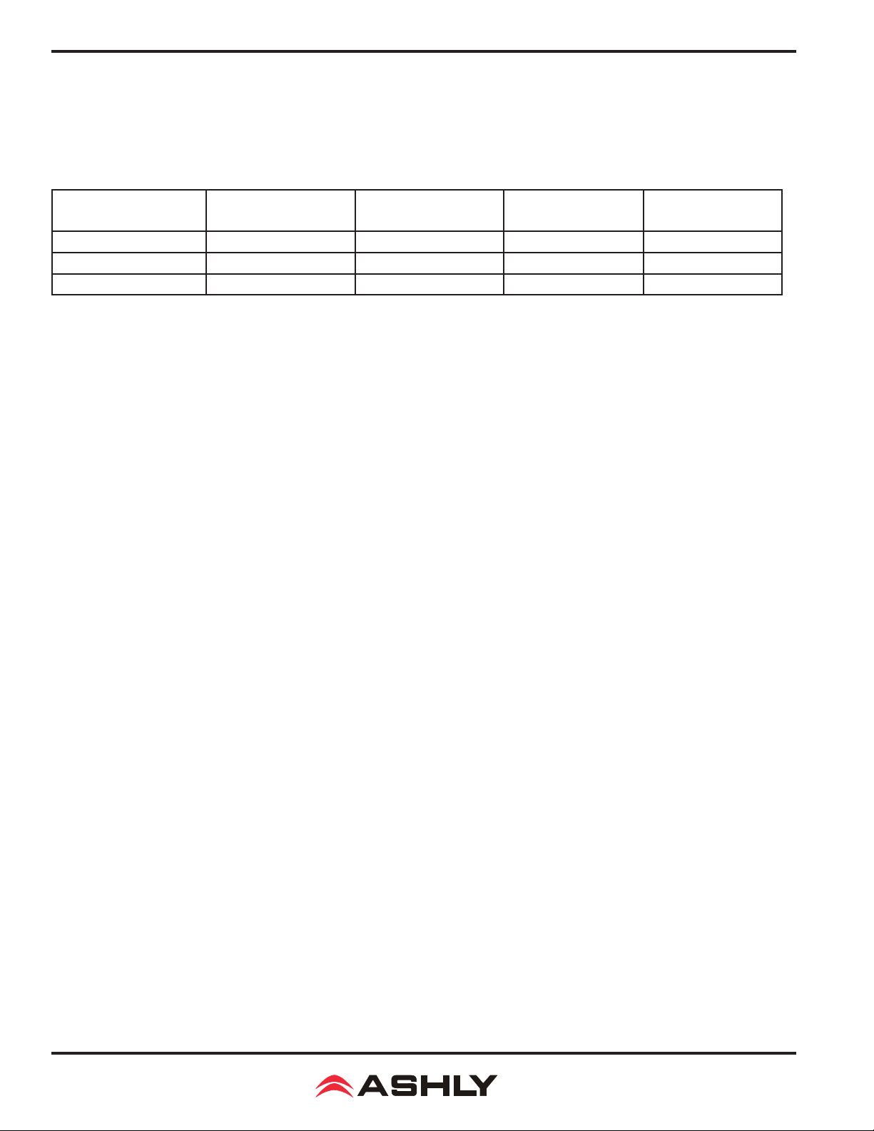
Thank you for your purchase of this Ashly nX, nXe, or nXp power amplier. This product uses state of the art, light weight, high
power, high efciency switching technology developed through years of design and eld testing. nX ampliers are available in
the following three series, designed to meet the most demanding live sound and xed installation sound systems in stadiums,
arenas, performance venues, worship spaces and convention centers.
400W @ 2 Ohm
Series
nX - Base Series nX4002 & nX4004 nX8002 & nX8004 nX1.52 & nX1.54 nX3.02 & nX3.04
nXe - Ethernet Series nXe4002 & nXe4004 nXe8002 & nXe8004 nXe1.52 & nXe1.54 nXe3.02 & nXe3.04
nXp -
Ethernet + DSP
2 and 4 channel
nXp4002 & nXp4004 nXp8002 & nXp8004 nXp1.52 & nXp1.54 nXp3.02 & nXp3.04
800W @ 2 Ohm
2 and 4 channel
1,500W @ 2 Ohm
2 and 4 channel
3,000W @ 2 Ohm
2 and 4 channel
nX - Base Series Standard Features
• Two or four channel high power, lightweight amplier design
• Individually congurable speaker outputs for Low-Z (to 2 Ohm), or High-Z (70V or 100V) via rear panel dip switches
• Front panel power switch and level controls, defeatable
• Front panel LEDs for temperature, current, signal, clip, mute, bridge mode, protect, sleep, and disable
• Combo XLR - 1/4" jack and Euroblock connectors on all inputs
• SpeakON® twist locking loudspeaker connectors for security, safety, and reliability
• Back panel DIP switches per-channel for selection of hipass lter, limiter, input gain, and speaker output conguration
• Remote DC level control per channel
•
• Power-saving automatic sleep mode, less than 1W, defeatable
• Continuously variable cooling fan
• Extensive protection circuitry
• Independent amplier and power supply circuitry
• Five year warranty
Automatic selection of 110-120VAC or 220-240VAC operation, 50-60Hz, with detachable PowerCON® AC connector
nXe - Ethernet Series Additional Features
• Ethernet control and monitoring of amplier functions, with front panel COM activity LED
• iPad® "Ashly Remote" application available for custom design of end user wireless control interface
• Serial data port for Ashly serial remote control devices such as the WR-5 or RD-8C
• Optional RS-232 data converter for third party controllers such as Crestron
• Software defeatable power switch and level controls
• Standby mode, 30% reduction from idle, triggered on or off by contact closure, software control, or event scheduler
• Programmable power-on delay for Off-to-On or Sleep-to-On transitions
• Preset recall via contact closure, software control, remote control, or event scheduler
• Aux preamp outputs
• Fault condition logic outputs
• Optional Cobranet® or Dante® network audio and AES3 digital audio input with zero-latency pass-through
nXp - Ethernet + DSP Series Additional Features
•
• Impedance monitoring of individual amplier outputs for quick and easy diagnosis of potential speaker problems
• iPad control of select DSP functions including gain, mute, matrix, A/B source select, PEQ lter level, and meters
• Networkable remote gain and zone control using Ashly neWR-5 and FR-8/16
Protea DSP including dynamics, gain, EQ, feedback suppression, FIR lters, matrix and auto-mixer, crossover, delay, and more
6
Page 7
Operating Manual - nX, nXe, and nXp Power Ampliers
2 nX INSTALLATION REQUIREMENTS
Before connecting to AC mains power, make sure that the mechanical installation, cooling requirements, wiring, controls, and
software are all set to the conguration needed for your particular application. Failure to do so could result in damage to the
unit or to other components in the system.
2.1 AC Mains Voltage, Power, and Current Requirements
This amplier will auto-detect AC mains voltage of 110-120VAC or 220-240VAC, 50-60Hz. At nominal 120VAC mains, the
allowed operating range is 70-135VAC to allow for brownouts or power surges, and for nominal 240VAC operation the range is
140-270VAC. Use only the provided AC cord or equivalent to connect to AC mains. Programmable Power-On Delay is available
on nXe and nXp series ampliers. All nX models have a xed, non-defeatable warm-up delay of about three seconds to protect
against excessive in-rush current when rst powered up or when waking from sleep. The model number and power consumption
are indicated on the back panel label placed above the AC inlet. To reduce the risk of ground loop hum, all sound system ground
references should originate at the same AC power distribution point. Do not lift or remove the amplier power cord ground pin.
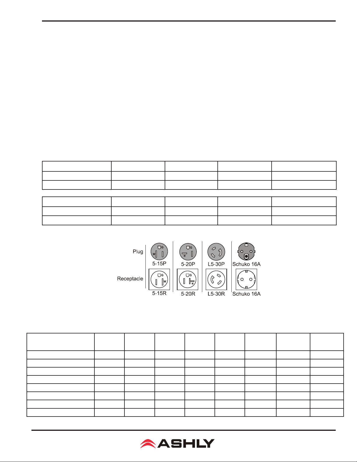
AC Mains Connector Types - The following table shows the AC mains plug type supplied with each nX amplier model,
as well as the required receptacle. A detachable 20A Neutrik PowerCON® mains chassis connector is installed on all models
except for nX 3.04, which uses a 30A PowerCON®.
nX4002 nX4004 nX8002 nX8004
120V Plug/Receptacle Nema 5-15 Nema 5-15 Nema 5-15 Nema 5-15
240V Plug/Receptacle Schuko 16A Schuko 16A Schuko 16A Schuko 16A
nX1.52 nX1.54 nX3.02 nX3.04
120V Plug/Receptacle Nema 5-15 Nema 5-20 Nema 5-20 Nema L5-30 (locking)
240V Plug/Receptacle Schuko 16A Schuko 16A Schuko 16A Schuko 16A
Total Mains Power Draw and Maximum Current Draw -
Total AC power consumption and maximum
120VAC current draw are shown below, measured at 1/8th maximum output power under typical amplier status and load conditions, all channels driven using typical audio signal. For 240V current, divide 120V values in half.
Total Power Draw
(Maximum Current@120V)
Sleep
Standby
Idle (no input signal)
1/8th Max Power @70V
1/8th Max Power @100V
1/8th Max Power @8 Ohm
1/8th Max Power @4 Ohm
1/8th Max Power @2 Ohm
nX4002 nX4004 nX8002 nX8004 nX1.52 nX1.54 nX3.02 nX3.04
<1W(100mA) <1W(100mA) <1W(100mA) <1W(100mA) <1W(100mA) <1W(100mA) <1W (100mA) <1W (100mA)
25W(0.38A) 40W(0.70A) 25W(0.38A) 40W(0.70A) 40W(0.70A) 70W(1.30A) 40W (0.70A) 70W (1.30A)
40W(0.70A) 70W(1.30A) 40W(0.70A) 70W(1.30A) 55W(1.0A) 100W(1.85A) 55W (1.0A) 100W (1.85A)
190W(2.6A) 375W(5.0A) 345W(4.6A) 685W(8.8A) 625W(8.0A) 1250W(16.0A) 940W (12.1A) 1880W (24.1A)
190W(2.6A) 375W(5.0A) 345W(4.6A) 685W(8.8A) 520W(6.7A) 1040W(13.4A) 520W (6.7A) 1040W (13.4A)
190W(2.6A) 375W(5.0A) 345W(4.6A) 685W(8.8A) 520W(6.7A) 1040W(13.4A) 520W (6.7A) 1040W (13.4A)
190W(2.6A) 375W(5.0A) 345W(4.6A) 685W(8.8A) 625W(8.0A) 1250W(16.0A) 770W (9.9A) 1540W (19.7A)
190W(2.6A) 375W(5.0A) 345W(4.6A) 685W(8.8A) 625W(8.0A) 1250W(16.0A) 1150W (14.7A) 2300W (29.5A)
7
Page 8

Operating Manual - nX, nXe, and nXp Power Ampliers
2.2 Input Signal Wiring
Use shielded wiring for balanced or unbalanced audio signals. Shielding which is properly grounded will protect the signal from
outside electrical interference such as RF, uorescent lighting, and computer/display emissions. Unbalanced or single-ended (tipsleeve) lines of less than 10 feet are generally ok, but for greater distance or noisy eld environments, always use balanced signal.
Each channel's Euroblock, 1/4" phone jack, and XLR inputs are wired in parallel, with XLR pin 2 (+) and pin 3 (-). When using an
unbalanced input, wire the hot signal to the input (+) euroblock pin, phone jack tip, or XLR pin 2, and also be sure to wire the input
(-) pin, phone jack ring, or XLR pin 3 to ground. Do not leave the (-) input unconnected. Avoid running low level signal wires in
close proximity or parallel to long speaker cables, AC power cables, or power transformers, as they can induce hum or oscillation.
2.3 Output Speaker Wire
Note: The sound system installer is responsible for using loudspeaker wiring that is in compliance with local
electrical code. The following recommendations for speaker wiring are based on UL 60065 section 5.2-d and the US National
Electrical Code Article 725. These are only guidelines, consult your local code for specic up to date requirements.
Class 2 wiring is typically used
is typically used if the measured open circuit output voltage exceeds 120V r.m.s, such as when 70V, 100V, or low-Z ampliers are used
in bridged mode. See
Output Speaker Connectors: nX amplier speaker outputs use Neutrik SpeakON connectors because they are safe, secure, reliable,
and fully enclose any hazardous voltage.
Wire guage: nX ampliers are capable of delivering high levels of output current, so the wire gauge used for speaker outputs is important. Inadequate wire gauge, especially over long distance, adds signicant resistance to the speaker’s own impedance, reducing
the power which is actually delivered to the speaker. It could also result in a decreased damping factor and potential re hazard. Since
power at the speaker load is of primary concern in system design, refer to the table below to best determine appropriate wire gauge for
your application. The following table lists the resistance per 100 feet of common copper wire gauges, and also lists the percentage of
the speaker load power which would be lost as heat in an arbitrary 100 ft run of different gauges of 2-conductor copper speaker wire.
Wire gauge resistance/power loss for 100ft speaker cable
Wire Gauge
#8 0.0605 Ohms 0.8% 1.5% 3%
#10 0.1018 Ohms 1.3% 2.5% 5%
#12 0.1619 Ohms 2.0% 4.0% 8%
#14 0.2575 Ohms 3.2% 6.4% 12.8%
#16 0.4094 Ohms 5.1% 10.2% 20.4%
#18 0.6510 Ohms 8.1% 16.3% 32.6%
This table expresses the power loss as a percentage of the load’s power rather than the total amplier output power in order to accurately determine power loss at other cable lengths. For example, if you plan to deliver 150 watts to an 8 Ohm load through 50 ft of
14 ga. cable, the power loss in the cable would be half that of a 100 ft run of #14 wire as shown in the table, or 1.6% of 150W, which
is an insignicant 2.4 watts. However, if you were to run 200 ft of 18 ga. cable to a 2 Ohm load, the loss would be twice that of the
100 ft run shown in the table, or 65.2% of 250W, which is 163 watts lost as heat. Always be sure to use adequate gauge speaker wire.
section 15
Ohms/100ft 8 Ohm load 4 Ohm load 2 Ohm load
when the maximum measured open-circuit speaker output voltage is less than 120V r.m.s. Class 3 wiring
for specic model congurations that may require Class 3 speaker wiring.
2.4 Remote Control Wire
Remote DC level control (all models) - Unshielded bell or telephone wire is sufcient for DC level control, as is CAT5 cable.
The V+ and GND pins from one amplier channel can be shared with other remote DC level controls wired to the same amplier, however do not connect this ground to any external grounds.
Remote Standby (nXe and nXp only) - This is a logic level signal, use unshielded low gauge wire.
Fault (nXe and nXp only) - This is also a logic level signal, unshielded low gauge wire is adequate.
Preset (nXe and nXp only) - This is also a logic level signal, unshielded low gauge wire is adequate.
Data (nXe and nXp only) - Four conductor telephone wire is suitable, as well as CAT5, but if shielded wiring is used be sure
to ground the source end of the shield. Under no circumstances should shielding be left unconnected to ground, as the added
line capacitance will degrade the data signal. Maximum data cable distance is 1,000 ft (305m).
8
Page 9
Operating Manual - nX, nXe, and nXp Power Ampliers
2.5 Aux Output Wiring (nXe and nXp only)
The aux outputs are pseudo-balanced, meaning they use single ended signal (+) but with balanced impedance, and can be wired
balanced or unbalanced. Always use shielded cable for audio signals.
2.6 Mechanical
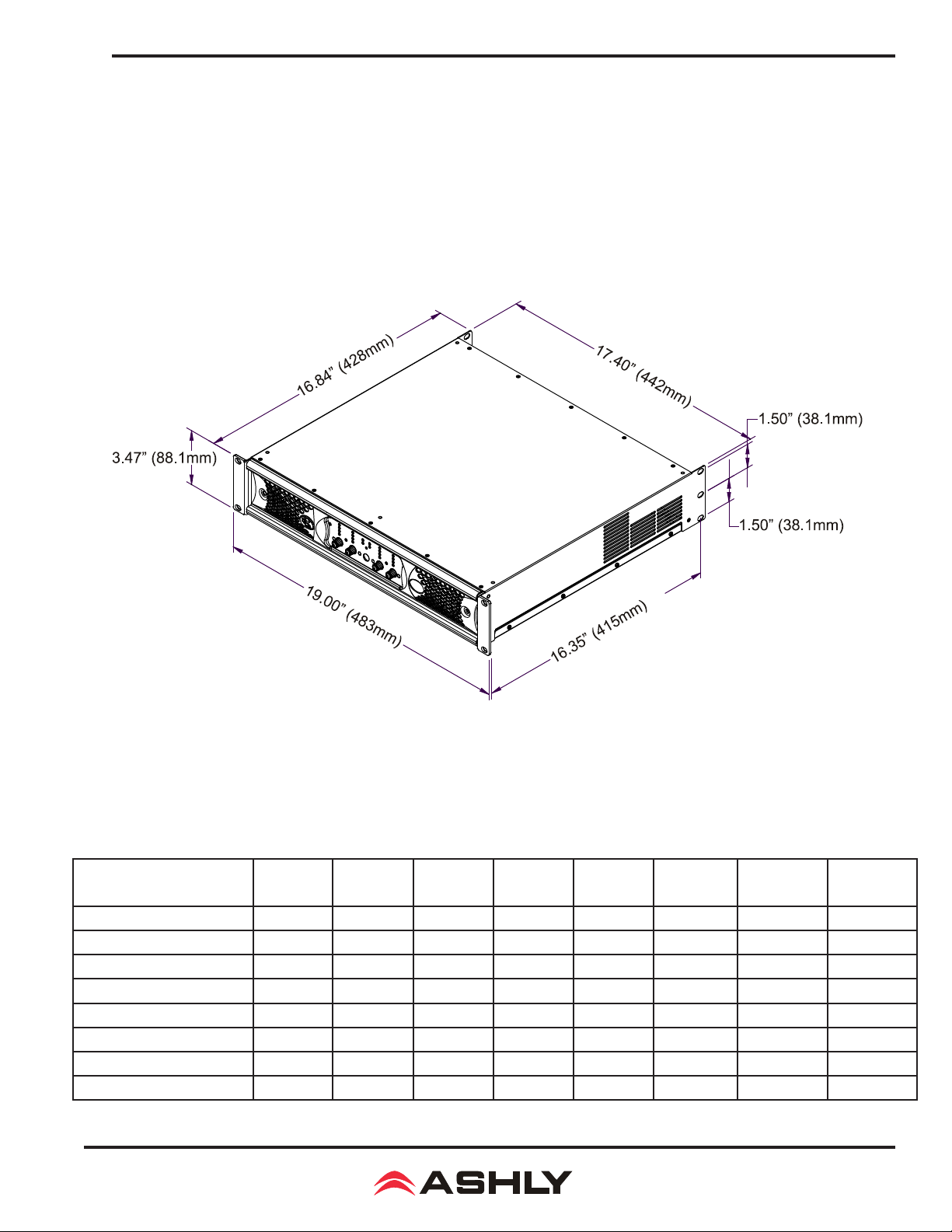
Each amplier model is 2RU, and is designed to t in a standard 19-inch equipment rack. Use four screws when mounting
the amplier to the front rack rails. Rear support is recommended for mobile or touring use (see mechanical drawing below).
In some installations where the sound system is exposed to a high level of RF noise or system-induced oscillation, it may be
necessary to ground the amplier’s chassis to the rack enclosure. This is accomplished using star type lockwashers on the four
rack mounting screws, placed between the amplier chassis and the rack rails. These star washers will penetrate through the
amplier and rack rail nish to adequately ground the chassis to the rack.
2.6 nX Dimensional Drawing
2.7 Cooling
Air vents on the amplier front and side panels must have access to free owing room temperature air. Cool air is drawn in
through the sides and blown out the front. It is not necessary to leave empty rack spaces above or below the amplier. See the
BTU/hr chart below for amplier thermal output characteristics.
Maximum Thermal Output in BTU/hr
Maximum BTU/hour
(Maximum Current@120V)
Sleep
Standby
Idle (no input signal)
1/8th Max Power @70V
1/8th Max Power @100V
1/8th Max Power @8 Ohm
1/8th Max Power @4 Ohm
1/8th Max Power @2 Ohm
nX4002 nX4004 nX8002 nX8004 nX1.52 nX1.54 nX3.02 nX3.04
<3.4 <3.4 <3.4 <3.4 <3.4 <3.4 <3.4 <3.4
85 136 85 136 136 238 136 238
136 238 136 238 187 340 187 340
305 595 495 970 850 1700 1110 2220
305 595 495 970 710 1420 710 1420
305 595 495 970 710 1420 710 1420
305 595 495 970 850 1700 905 1810
305 595 495 970 850 1700 1360 2720
9
Page 10
Operating Manual - nX, nXe, and nXp Power Ampliers
3 nX AMPLIFIER PROTECTION
Power-On Delay -
awakened from sleep. nXe and nXp models additionally offer programmable Power-On Delay of up to 25 seconds (see section 9.2).
Thermal Protection -
80% of it's safe operating temperature, also turning on theTemp LED. At 90%, the Protect LED turns on to indicate countermeasures have been applied to attenuate the input signal to the overheating channel. A Temp LED turns on dim at rst, then increases
in brightness as the amp channel approaches maximum safe temperature. 100% critical temperature will shut down the amplier.
Overpower Protection - To protect internal components against overpower conditions, a protection scheme in each output stage
reduces audio output power until the fault condition is no longer present.
Output DC and Rail Fault Protection – Output DC on any channel will trigger the Protect LED and mute that channel. Voltage
rail irregularities such as power supply pumping are also detected and compensated for in real time as the amp runs.
AC Mains - If the AC Mains line voltage exceeds or falls below the specied operating range, the amplier will temporarily
shut down. It will automatically restart as soon as the AC line voltage returns to the specied range.
For details on these and other amplier protection schemes, plus their LED codes, refer to Troubleshooting in section 14.
All models have a three second warm-up delay to prevent excessive in-rush current when rst powered on or
Cooling fans are continuously variable, reaching their maximum speed when an amplier channel reaches
4 nX FRONT PANEL FEATURES (all models)
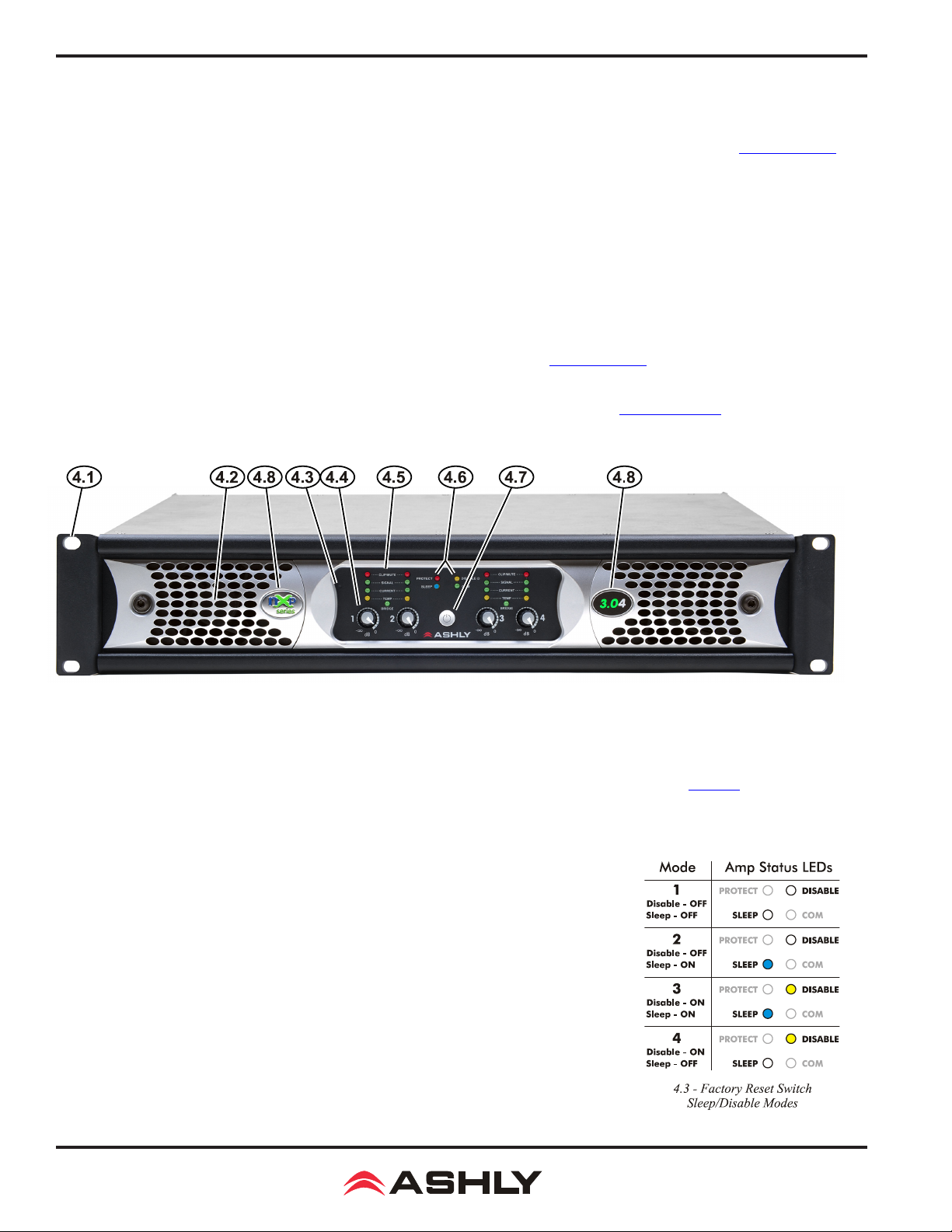
4.1 Mounting Holes – For mounting to a 19" equipment rack.
4.2 Air Vents – Cool air enters in through the amplier sides and is vented out the front.
4.3 Reset/Sleep Mode/Disable Switch – This recessed switch is used to reset the amplier to its default factory settings,
however it will not erase amplier presets. Proteane software must be used to erase amplier presets (sec 9.2g). This switch is
also used to set sleep mode and front panel disable status (see below).
To reset amplier settings, routing, networking, and security (not presets) to original factory defaults, use a plastic paper clip
or equivalent to press and hold the switch during power up until all channel LEDs sequence
from bottom to the top. Release the switch before the LED sequence is complete to cancel
the process. Upon completion, all LEDs turn off and the amplier resumes normal operation.
Setting Sleep and Front Panel Disable Mode - The factory reset switch is also used to select
one of four sleep and front-panel-control-disable modes as illustrated to the right. The default
status is Sleep and Disable OFF (Mode 1). To advance to the next mode, press and hold this
switch when the amplier is fully on, and the four mode combinations will cycle and repeat.
To select a mode, simply release the switch when the desired mode is displayed.
The Disable LED is lit any time the front panel controls are disabled, either by selecting disable
mode from this switch or using software control.
The sleep LED turns on during the mode-select cycle whenever sleep mode is enabled, but turns
back off as soon as the switch is released, remaining off unless the amp actually goes to sleep.
The current sleep mode status can be displayed when the amp is fully on by quickly pressing
and releasing the reset switch. If the sleep LED lights, sleep mode is active.
10
Page 11

Operating Manual - nX, nXe, and nXp Power Ampliers
4.4 Channel Attenuators –
fader level controls and the software control surface fader controls (if the amp is networked). When an input attenuator is turned
fully off, it's red Clip/Mute LED turns on and stays on to indicate mute status for that channel. The front panel attenuators can be
disabled, along with the power switch, using the factory reset switch as shown in section 4.3 or using software.
These control the input signal level to the amplier, and work in conjunction with the remote DC
4.5 Channel LED Indicators
BRIDGE - This green LED indicates when the channel pair is congured to BRIDGE mode from the back panel switch. Only
the odd numbered input and level control for that channel pair is used.
TEMP - This yellow LED turns on when an amplier channel has reached an operating temperature that is 80% of it's maximum safe range, and the cooling fan(s) are at their maximum speed. The LED lights dimly at rst and will glow brighter if the
temperature increases.
CURRENT - This green LED lights proportionately with the output current delivered to the speaker load.
SIGNAL - This green LED lights when the output voltage reaches -18dB from full output.
CLIP/MUTE -
preamp signal is clipped. MUTE: The LED indicates mute when the channel is muted or when it's level control is fully attenuated.
Additionally, the Clip/Mute LED is used along with the Protect LED to indicate an output DC fault (see section 14).
CLIPPING: The red LED indicates clipping when speaker output is 1dB below rated output, or when the input
4.6 Amplier Status LEDs
PROTECT -
temperature, or rail voltage fault conditions while the amp is still running. If those countermeasures are unsuccessful and the amplier
protects itself by shutting down, the Protect LED remains on and the amplier's power must be cycled before resuming normal operation.
The exception to this is when the amp shuts down due to the AC Mains voltage being out of range, in which case the amp automatically
restarts as soon as the AC mains line voltage returns to the specied
The red Protect LED initially turns on to indicate that real-time countermeasures are being applied to overpower, over-
operating range
. See section 14
for full details
.
SLEEP -
down most amplier circuits after a period of audio inactivity, reducing the amplier's power consumption to less than 1 Watt. An
amplier is awakened when there is audio signal present again, or when the power switch is pressed. Because the real-time-clock
is also shut down during sleep mode, the amplier cannot be awakened by any software function, including the event scheduler.
Sleep mode is normally disabled, therefore must be enabled by the user. On nX series, the sleep clock timer is xed at 30 minutes,
and is enabled by toggling through the four mode conditions of the factory reset switch as detailed in section 4.3. On networked
nXe and nXp series, the sleep clock timer also defaults to 30 minutes, but is programmable under [Device Options] with a range
of 1-120 minutes. In all models, the presence of input signal above -24dBu (0.05Vrms) or pressing the power switch will return
the amplier to normal operation. On all models, a xed amplier turn-on delay of three seconds is necessary to manage in-rush
current during power-up or waking from sleep. Sleep mode has priority over standby mode.
DISABLE -
controls are disabled together using the factory reset switch as described in section 4.3, or in software using the amplier's main
control surface (see section 9.4a).
COM -
ashes for two seconds when the <Identify Device> software button for that device is clicked. (see section 9.1i) Lastly, the COM LED
becomes lit (along with the ashing power switch LED) during ash reprogram mode.
4.7 Power Switch/LED –
white switch LED lights solid when the amplier is on, and ashes when in standby mode (nXe and nXp only). The power switch
can be disabled using the factory reset switch actions described in section 4.3, or disabled from software (nXe and nXp only). The
three possible power switch LED conditions are:
1) Fully lit: The amplier is powered up, even if the power switch has been disabled, in which case the disable LED will be on.
2) Flashing: The amplier is in standby mode, or is in ash reprogram mode when the COM LED is also lit.
This blue LED indicates that the amplier is asleep. Sleep mode can be enabled as a power saving feature that shuts
This yellow LED lights when the front panel power switch and level controls have been disabled. All front panel
For nXe and nXp models only, this green LED lights whenever network communication occurs. Secondly, the COM LED
This switch is used for powering the amplier on or off or waking the amplier from sleep. The
3) Fully off: The amplier is either completely off, or it is in sleep mode, in which case the blue sleep LED will be on.
4.8 Series and Model Labels – The label on the left indicates the amplier series, nX, nXe, or nXp. The label on the
right shows the amplier model name.
11
Page 12
Operating Manual - nX, nXe, and nXp Power Ampliers
5 nX SERIES REAR PANEL FEATURES
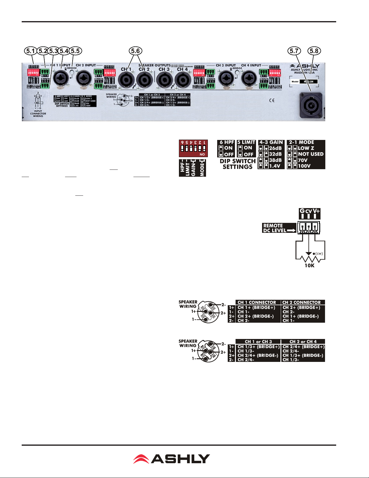
5.1 Channel Conguration DIP Switch - The DIP
switches congure each channel's 80Hz 2nd Order Hipass
Filter, Output Clip Limiter, Amplier Gain, and Output
Mode. In the example to the right, the DIP switch is set as
follows: 6: 80Hz High Pass Filter is Off; 5: Clip Limiter is
On; 4&3: Gain is 1.4V; 2&1: Output Mode is Low Z.
Note: The Gain setting of 1.4V means that a 1.4V input will drive
the amp to full output in any output mode. The other three Gain settings will apply their
respective amplier gain regardless of output mode, so the actual input voltage required
to fully drive the amp will vary based on the selected output mode.
5.1 Channel Conguration DIP Switch
5.2 Euroblock Input Jack - Used for wiring a balanced input. If using an unbalanced
signal, wire the input signal to the (+) pin, the shield to (G), and wire the (-) input pin to
ground. Euroblock pins are wired in parallel to the
5.3 Remote DC Level Control -
remote DC Level Control. The example to the right illustrates a typical DC level control application.
There is no limit to wire length, but do not use any other ground source. If multiple remote DC level
controls are used for different channels, the same ground and V+ sources can be shared.
5.4 Combo Input Jack -
parallel to the euroblock input. Do not oat the TRS ring or XLR pin 3, connect it to (-) signal or
to ground (if unbalanced).
The combination 1/4" TRS and XLR jack (pin 2 hot) is wired in
5.5 Bridge Mode Switch -
channel pair into bridge mode, combining two amplier outputs
for more power to a single speaker load. Bridge mode uses only the
odd numbered input channel and level control, disabling the even
numbered input. Speaker outputs for bridge mode must be wired
according to the chart shown to the right. The bridge mode switch
button can be removed for added security by pulling it straight off.
Each channel has a potentiometer circuit available for
This switch places an adjacent
1/4" TRS and XLR
combo jack.
5.6 Speakon Wiring: Two channel ampliers
5.3 Remote DC Level Control
5.6 SpeakON® Output Jack Wiring -
jacks provide safe, secure, and reliable loudspeaker connections,
preventing external contact with potential hazardous voltage. See the speaker wiring diagram above or on the amplier back panel for
SpeakON pin connections and channel assignments for normal or bridge mode speaker wiring. See sec 5.5 to use bridge mode.
5.7 PowerCON® AC Mains Connector -
amplier auto-detects mains voltage from 120VAC to 240VAC. WARNING: Do not remove or lift the mains connector ground.
SpeakON output
Always use the AC cord provided by Ashly for connecting to mains power. The
5.6 Speakon Wiring: Four channel ampliers
5.8 Serial Number Sticker - This sticker identies the product model number, serial number, MAC address (if network-
able), and AC mains current/power rating.
12
Page 13
Operating Manual - nX, nXe, and nXp Power Ampliers
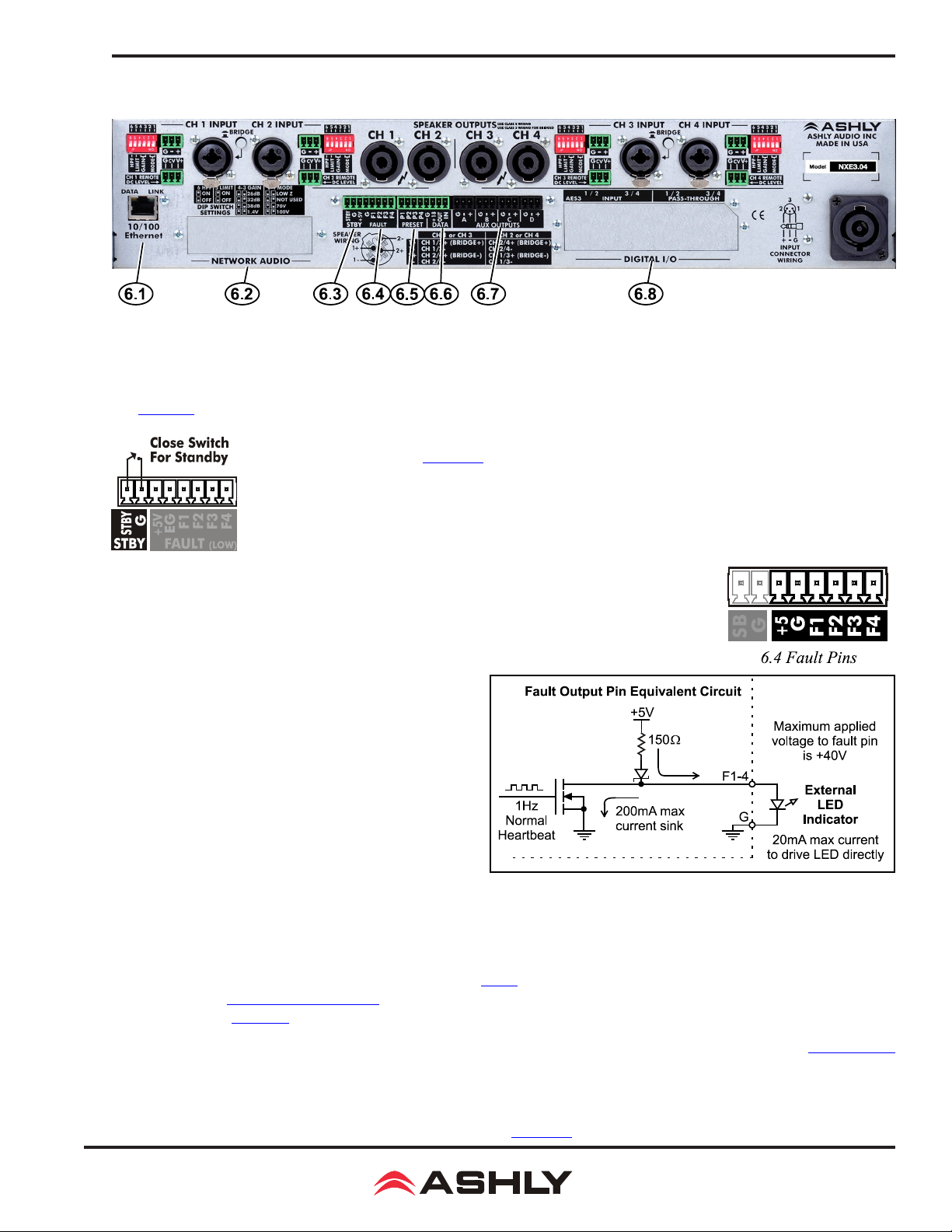
6 nXe SERIES REAR PANEL FEATURES
The following nXe features are in addition to standard features found in nX series ampliers:
6.1 Ethernet Port - This RJ-45 connector offers Ethernet control and monitoring of the amplier using Protea
See section 8 in this manual for details on Ethernet communications.
6.2 Network Audio -
on nXe and nXp models. See section 13 for details.
This is for an optional factory installed CobraNet or Dante network audio module
6.3 Standby Contact Closure - The STBY pin, when connected to the ground pin (G) as shown,
will remotely place the amp into standby mode. When the connection is opened, the amplier returns to
normal operation. The front panel power switch will ash when the amplier is in standby.
6.4 Fault Pins - A fault logic output pin is available for each amplier
6.3 Standby Circuit
er problem. A fault is indicated by the loss of a normally present "heartbeat" signal, where the
output continuously toggles between 0V and +5V at a 1Hz rate.
The normal heartbeat signal on each fault pin is interrupted
whenever a fault condition prevents normal function of that
channel while the amplier is either powered on or in the
standby state. Fault conditions include loss of AC mains
voltage, excessive internal temperature, power supply
voltage out of range, DC on output, or microprocessor
malfunction.
as shown in the circuit illustration to the right.
If a fault occurs, fault pin output may be latched <Low> or
<High> depending on the type of fault or state of the output
at the moment the fault occurred. A fail-safe fault detection
circuit should monitor and respond only to the loss of the
1Hz heartbeat signal.
A fault pin output can directly drive an LED
output channel. Fault pins are used to drive external LEDs or connect
with equipment that can remotely monitor or respond to a serious ampli-
ne
software.
6.5 Preset -
to recall a stored preset or sub preset from the amplier. Preset pins 1-4 correspond directly to amplier presets 01 - 04.
6.6 Serial Data Connector -
WR-5 or RD-8C. Ashly also offers an in-line converter called the INA-1 which allows the data port to be used with third party RS-232 controllers. A technical RS-232 protocol document is available on the Ashly website for third party developers. See more data remote control
application details in section 10.
6.7 AUX Outputs -
on page 59 for the differences between two and four channel amplier AUX outputs. AUX outputs are pseudo-balanced, meaning
they use single ended signal with balanced impedance, and can be wire balanced or unbalanced.
6.8 AES3 Digital Audio I/O Option -
available as a factory installed option on nXe and nXp models. See section 12 for AES3 details.
Each pin (P1 through P4) can be connected to the adjacent ground pin (G) via Ashly's WR-2 remote or other contact closure
These four pins (G, +18, OUT, IN) are for connecting a serial data remote control such as an Ashly
These Euroblock connectors provide preamp signals for driving other ampliers. See the block diagram
This is used for Ashly's two or four channel AES3 input and pass-through module,
13
Page 14
Operating Manual - nX, nXe, and nXp Power Ampliers
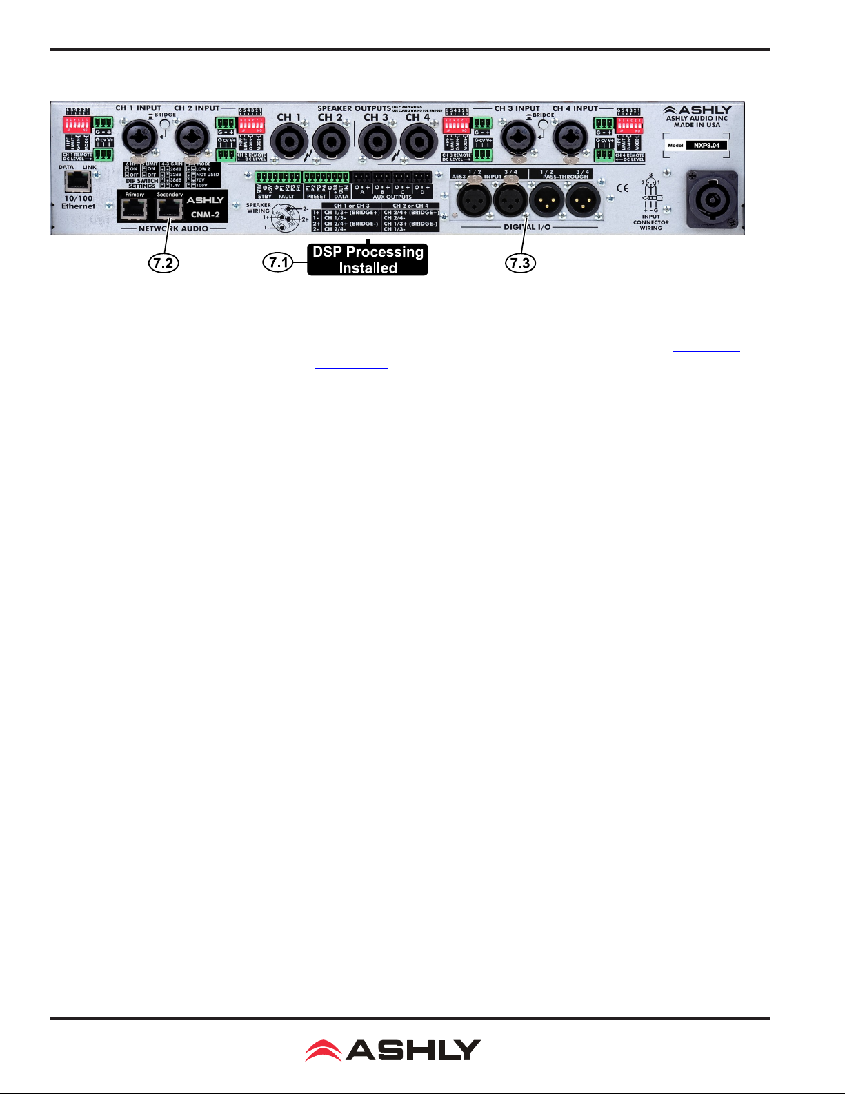
7 nXp SERIES REAR PANEL FEATURES
*The following nXp features are in addition to all of standard features found in nX and nXe series ampliers:
7.1 Installed DSP - Factory installed DSP allows for comprehensive signal processing of amplier signals (section 9.4d)
as well as loudspeaker load impedance analysis (section 9.1i).
7.2 Network Audio - CobraNet or Dante network audio modules can be factory installed in nXe or nXp models.
7.3 AES3 Digital Audio I/O - AES3 digital audio module can be factory installed in nXe or nXp models.
8 ETHERNET COMMUNICATIONS (nXe and nXp models only)
Ethernet communication is made by connecting the amplier directly to a PC running Proteane software or connecting through a network router,
switch, hub, or patch panel using Cat-5, Cat-5e, or Cat-6 wiring. Maximum Ethernet cable distance is 100 meters (328 ft). Ashly nXe and
nXp ampliers will adapt to either a straight through pin to pin or crossover Ethernet cable. For wireless iPad control using a custom "Ashly
Remote" user interface, the iPad must be connected to a wireless access point that is connected to the same network (subnet) as the amplier.
8.1 IP Address - There is no need to assign an IP address to nXe ampliers. The router or Link Local Addressing will assign
IP addresses to each device automatically.
When a router is not available, each amplier will acquire it's own IP address based on Link Local Addressing. This allows the
device to operate without the need to set up static IP address. If the only option is to use an Ethernet switch instead of a router,
and communications problems remain which cannot be solved with the use of the link local standard, each device can have
a static IP address assigned from within Proteane software. This is done by selecting “Manual Conguration” in the Network
Properties tab of each device, where the system/network administrator must assign each product its’ own unique static IP address, each with the appropriate sub net if applicable.
8.2 Firewalls -
have Proteane software added to its rewall exceptions, since rewalls may block the amplier response to the PC. The current PC rewall
status is found by clicking on the Windows Start button, then Control Panel, then double clicking on the security shield where rewall
exceptions are congured.
8.3 Wi-Fi and LAN –
the PC, and the LAN (Local Area Network) connection must be enabled on the PC. Secondary network connections may confuse the
auto device discovery process. Go to the Windows Control Panel, then Network Connections, to disable any secondary network connections. Once communications with the device is established, secondary network connections can be enabled again.
If Proteane software does not detect the amplier or show real time changes, the rewall in the host PC may need to
For the initial device auto-conguration process, any secondary Wi-Fi connection should be disabled on
8.4 Connecting Device(s) - Connect the Ethernet cable from the PC or network to the amplier. If a successful Ethernet
connection has been made, a solid green LED (Link) lights up on the amplier's RJ-45 Ethernet port. If there is no green LED
showing, there is either a problem with the cable or the network source which must be addressed before proceeding further. All
RJ-45 Ethernet ports ash green when active, so backtrack through any other cables, routers, or switches to nd the problem.
The ashing yellow LED (Data) indicates that data is owing to or from the amplier.
14
Page 15
Operating Manual - nX, nXe, and nXp Power Ampliers
9 PROTEA™ SOFTWARE
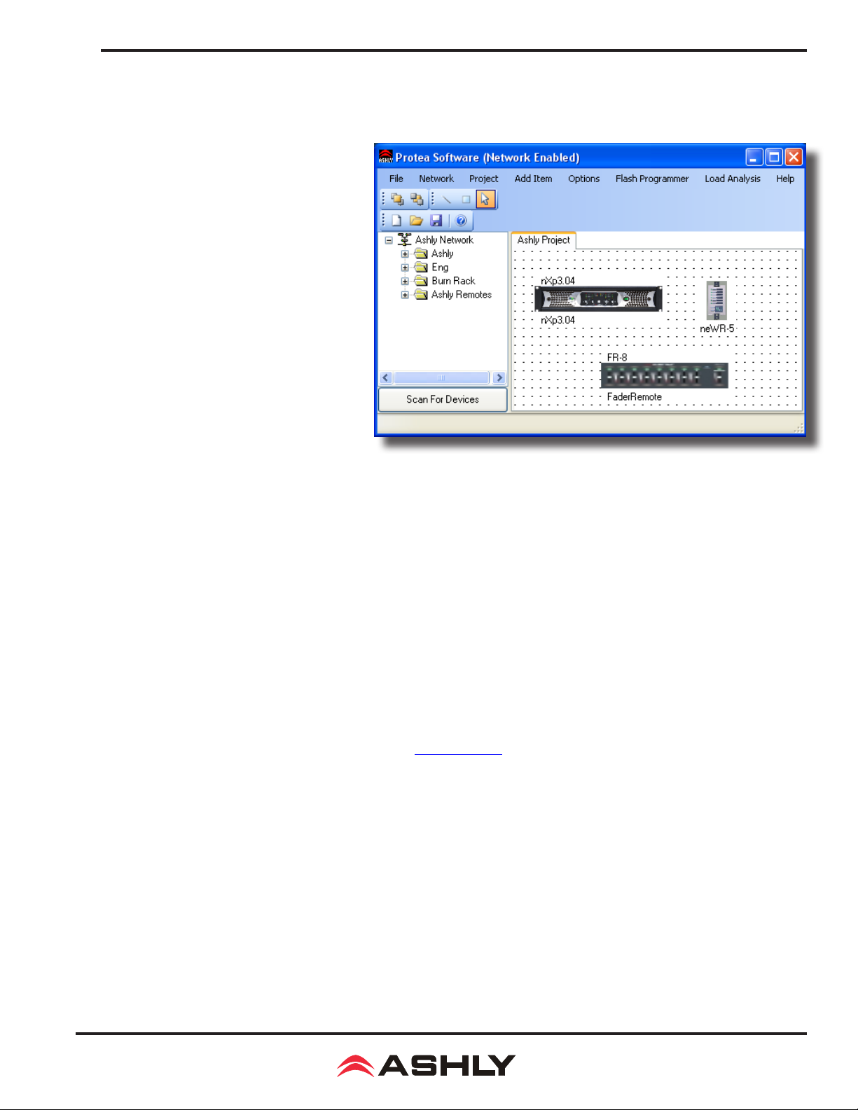
9.1 Installing and Using the Software
Ashly Protea software is available for free
download from the Ashly website's software
section. There is no longer a CD-ROM
included with new units. After downloading,
installing, and launching the program, the
startup screen will appear as shown to the
right, with Ashly Network Tree, Project
Canvas, and Menu items described below:
9.1a Ashly Network Tree - The Ashly
Network device tree on the left side of the
software start-up screen is an accurate reec-
tion of all Ashly devices currently installed
on available networks. A green device name
means it is a live device, a red device name
means it was previously installed but is now
off-line, and a yellow device name means
it is live but configured incorrectly. All
Ashly devices broadcast their availability to
the software when they start up. The user can
also manually scan for devices with <Scan For
Devices> found below the network device tree.
9.1 - Proteane Software Startup Screen, Device Tree, and Project Canvas
Devices can be dragged from the device tree and placed onto the project canvas as icons to simulate rack installation groups,
or be added as virtual devices using the [Add Item] menu command with [Design Mode] checked On. Editing a device can be
done from either the device tree or from it's representative icon on the canvas. All software changes made to a live device are
executed in real time.
The software automatically detects and displays controls for any installed device options. DSP, CobraNet, Dante, and AES3 are
currently available, AVB network audio will be available in the future.
Note: The user can nd and verify a live device on the network by right clicking over the unit’s name or icon, and then click
<Identify> which will ash the device's Com LED for two seconds.
9.1b Ashly Project Canvas - The project canvas is used to represent a sound system installation as a visual project. Networked
devices can be dragged from the Network Tree onto the canvas and congured. Virtual devices can be added to the canvas
as well, congured, and later assigned to a live device (see section 9.1f). Live networked devices appear with a green border,
off-line network devices have a red border, and virtual devices appear without any border. The primary canvas is always called
"Ashly Project", but additional project les can be saved under different names.
Additional visual control objects such as level faders, LEDs, meter bars, preset, standby, mute, and source select buttons can be
placed on the canvas and assigned to control a specic parameter on one or more devices in the project. Use [Add Item>Control
Objects>(object)] to place a control object on the canvas, then double-click or right-click to edit its properties. Use [Add
Item>Display Objects>] to place an image or text on the canvas. Additional drawing tools are found in the upper left corner
above the canvas and include lines and rectangles. The user can alternately right click anywhere on open canvas to add items.
Checking <Design Mode> allows placed objects to be moved around, while unchecking <Design Mode> locks objects in place.
15
Page 16

Operating Manual - nX, nXe, and nXp Power Ampliers
9.1c File Menu -
stand-alone control objects and their settings, as well as drawn or linked graphical objects placed on the project canvas.
[File>Open Project] - opens a project le (*.cpj) from the computer
[File>Save Project] - saves all data on the project canvas, and can additionally save all presets on devices in the project
[File>New Project] - clears the canvas, clears all data, and clears all project tabs other than the "Ashly Project" tab
[File>Print Setup] - This determines the target printer for an individual device's parameter settings report, available by right-
clicking on any live device in the device network tree. All current device settings are written into the printable report.
[File>Warnings] - These three software warning messages can be turned off; <DSP Channel Disable>, <Sampling Frequency
Change>, and <DSP Full>. Ashly recommends leaving all three warning messagess turned on.
[File>Log] - The Log Control allows the user to adjust what parameters are logged to the Ashly Event Logger, which maintain
a log of all changes made to a
this does allow a user to know what has happened in the past to the system. The Event Logger uses the Windows Event Handling
System to log events, which can be viewed and cleared using the Windows Event Logger (Start>Control Panel>Administrative
Tools>Event Viewer>Protea NE Software).
A project le (*.cpj) contains a snapshot of all current settings for live and virtual Ashly devices. It also contains
Proteane System while
Proteane Software is running. For most users this is not important; however,
9.1d Network Menu
[Network>Scan For Devices] - This command looks on the local network (using the broadcast address) for any Ashly network
enabled device. Any devices it nds will be added to the network device tree. This scan is done automatically when the software
is started. A button of the same name and function is also found beneath the network device tree.
[Network>Network Cong] - Adjusts the metering refresh rate, server retries, server timeout, and heartbeat timer.
9.1e Project Menu
[Project>Tab Page>Add, Remove, Rename, and Clear] - Multiple project tabs can be used within the same project to represent
different racks, rooms, buildings, etc, and are managed using these four commands.
[Project>Save/Recall Preset To/From All Devices] - This is used to save or recall all device parameters in the current project,
based on preset number. When using <Save Preset to All Devices>, a unique preset le is created for each device and saved to
the same preset number across all devices, overwriting the current preset parameters for that number. When using <Recall Preset
From All Devices>, the chosen preset number will be recalled from each device.
9.1f Add Item Menu
[Add Item>Design Mode] - With Design Mode checked On, virtual Ashly devices can be placed on the canvas and congured
before connecting to the live network devices they will control. This way, a complete system installation can be set up ahead of
time in software and saved as a project to be applied later. To apply the prepared project le, use the following steps:
1)
Connect all Ashly devices to the network and launch the software, verifying that all devices appear green in the network device tree.
2) Open the project le and link one device at a time by dragging each network device from the device tree onto its virtual
device icon represented on the canvas. You will be prompted by the message <Copy all settings from canvas device to online
device?>, after which all virtual device settings will be applied to the live networked device. A live device icon on the canvas
is indicated by a green surrounding box, whereas a virtual device has no green surrounding box.
With Design Mode unchecked, all device icons, control objects, and display objects on the canvas are locked in place.
16
Page 17

Operating Manual - nX, nXe, and nXp Power Ampliers
[Add Item>Control Objects] - Stand-alone control objects can be added to the canvas and linked to control specic device
functions. They include Level Fader, Signal LED, Level Meter, Preset Button, Standby Button, Mute Button, Logic Out Button,
and Source Select Button.
[Add Item>Display Objects] - Text and image les can be added to the canvas.
9.1g Options Menu
[Options>Auto Add Online Devices] - When this is checked On, all network devices appear on the canvas whenever the soft-
ware is launched or when the networked is scanned for devices.
[Options>Display Grid] - Turns on or off the project canvas grid
[Options>Auto-Close Preset Recall Messages] -
If this is checked On, those messages will go away automatically, otherwise they will stay on the display until closed by the user.
Any device that recalls a preset will trigger a message that appears on the canvas.
9.1h Flash Programmer Menu
[Flash Programmer>Launch Flash Programmer] - This is used to update the rmware on any networked Ashly device. All
available rmware update les can be downloaded from the Ashly website.
[Flash Programmer >Launch WR-5 Flash Programmer] - WR-5 rmware must be updated through its hosting device, since
WR-5 remote controls are not themselves networked. Download the new WR-5 rmware, select the host device, and follow
the instructions.
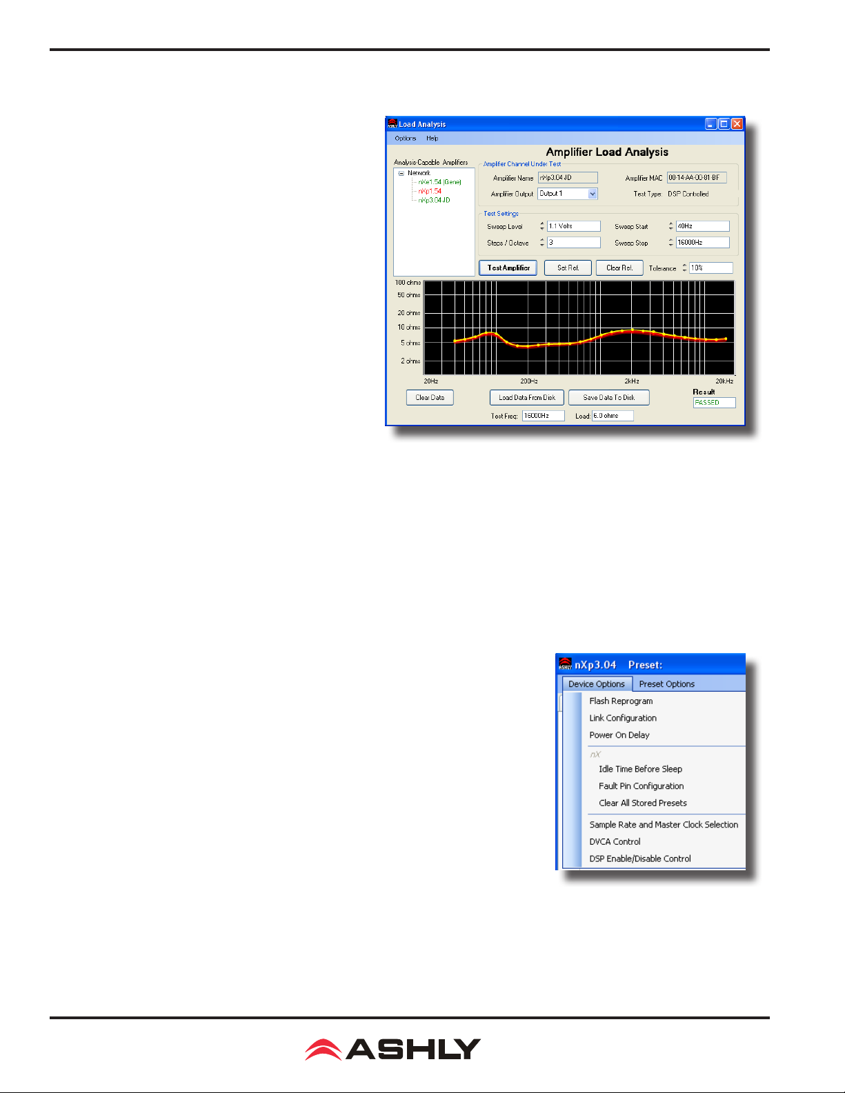
9.1i Load Analysis Menu - Load Analysis is a software tool used to visualize the swept AC impedance of a given loudspeaker,
and to test the integrity of a potentially damaged loudspeaker or connection. Load impedance analysis works by formulation of
speaker output measurements taken when a user dened swept sine wave input is applied to one amplier channel by software.
Currently, the only Ashly ampliers with load analysis are NE two-channel (dsp) and nXp.
Loudspeakers are specied with a nominal impedance rating, 8 Ohms for example. This is an average rating, the actual impedance across it's frequency range can vary substantially above or below 8 Ohms due to
ties which affect impedance
current delivered to the speaker. This can present a problem when wiring multiple speakers in parallel, as the combined speaker
impedance may become so low that it causes the amplier to go into overcurrent protection mode and shut down. The way to
avoid this is to pay attention to the lowest measured impedance rather than the nominal impedance rating for a given speaker
load, and make sure the amplier is rated to drive that load.
. Lower impedance, even within a narrow frequency range, can increase the amount of amplier
inductance, resonance, and other proper-
A second function of load analysis is for troubleshooting loudspeakers. When loudspeakers are damaged by overheated voice
coils, torn cones or surrounds, mechanical damage from being dropped, or have corroded connections, they can exhibit different
load impedance characteristics than when new. An initial load impedance analysis can be performed when the system is rst
installed and the results saved to disk for reference. Future load impedance tests can be compared to the original reference data
and issue a pass/fail rating based on a user-dened percentage of similarity to the original data. Load anaylsis can thus help
determine if loudspeakers are damaged or disconnected, and can be administered from a remote network location.
Keep in mind that this test is a real time audible event, so be certain that all test parameters, particularly volume (sweep level)
and frequency range (sweep start/sweep stop), are suited for the speakers under test, and that the venue is ready for a brief
period of test tones at potentially signicant volume. Note: During the test, all audio DSP processing in the amplier is stopped.
17
Page 18
Operating Manual - nX, nXe, and nXp Power Ampliers
[Load Analysis>Launch Load Analysis] - This is the working window for performing a load analysis. The user must rst
select an available networked amplier from the <Analysis-Capable Amplier> device tree, then select the output channel to
test, then apply the appropriate test settings.
Warning: Do not send low frequency test tones to high
frequency drivers or use excessive sweep level, always be
certain that the swept frequency range and output level is
within the safe operating range of the speaker under test.
Remember that all DSP functions are disabled, including
crossover lters and limiters. A sweep level setting of 1V
will produce a relatively quiet test tone into any speaker,
however load impedance characteristics can change at higher
volume levels, so test accordingly but carefully. Make sure
the Sweep Level and Sweep Start Frequency are
properly set for this loudspeaker before running the
test! Click on <Test Amplier> and a series of tones will
be heard through the loudspeaker under test. The test can be
immediately cancelled by pressing the same button again.
When the test is nished, a plotted curve (yellow) shows
load impedance vs. frequency. Click <Set Ref.> to establish
this curve as a reference (red) baseline, or save the data to
disk for future tests.
Note: Running the load analysis tool when there is no speaker
connected to the amplier is useful for learning about the
procedure, but provides no meaningful data.
9.1i Load Analysis
9.1j Help Menu -
[Help>About
[Help>Contents and Index] - Online help for device function is found here, along with the ability to search for topics.
[Help>Capture Network Conguration] - While most people will not use this function, it can be helpful when troubleshooting
network problems or communicating with Ashly technical support.
Proteane Software] - Tells the software version
9.2 nX Device Options Menu
Double-click on a nX amplier in the Network tree or on the canvas.
9.2a Flash Reprogram Mode - A
ing a new program le (rmware) to the amplier over the network. Latest rmware updates,
if available, can be found on the Ashly website. When the amplier is put into ash reprogram
mode, all audio functions are suspended, the power switch LED ashes, and the COM LED
remains lit until ash reprogram is completed. Flash Reprogram only appears in the device options menu when a live device is connected.
nX amplier can be ash reprogrammed by download-
9.2b Link Group Conguration - Link groups allow DSP functions of the same type to
track each other across channels within a device. For example, if two separate EQ controls
on different channels are linked, any change made to either one of the equalizers will result
in an identical change to the other.
nX ampliers support up to 16 Link Groups, and every DSP tool can be assigned to one of these groups. Once assigned to a
group, all similar DSP functions within that group will track parameter changes with each other. More than one type of DSP
function block can be assigned to the same group. Each link group can be assigned a name by the user, and can also be assigned
a color for easy identication. For further details about linking, see the online help in Protea
9.2 Device Options
ne
software.
18
Page 19
Operating Manual - nX, nXe, and nXp Power Ampliers
9.2c Power On Delay -
Delay is measured in increments of 100mS, with the limit at 25.5 seconds. The power amplier should be the last device to power
up after other system components have turned on and stabilized. Multiple ampliers on the same circuit breaker should have staggered Power-On Delays to avoid excessive in-rush current which can trip the breaker.
Use this feature to delay the amplier turning on when rst powered up or when waking from sleep.
9.2d Idle Time Before Sleep - On nXe and nXp series ampliers, the sleep clock timer can be set from 0 to 120 minutes
9.2f Factory Installed Options (not shown) - Factory installed options currently include AES3, CobraNet, or Dante. Options
are auto-detected on live ampliers, but can be added to virtual ampliers when working in Design Mode.
9.2g Clear All Stored Presets - nXe and nXp only.
9.2h
Sample Rate and Master Clock Source Selection:
Advanced Control> box in this menu item. Sample rate can be set to either 48kHz or 96kHz. Note that at 96kHz, the DSP usage
doubles, resulting in half the available processing power for lters, delay, limiting, etc. Also note that the Feedback Suppressor
cannot be used at 96kHz sample rate. Factory default settings are Auto Selection for clock source and 48kHz sample rate.
Changes to both of these settings can be made by clicking the <Show
9.2i DVCA Control - This feature is used in conjunction with the DSP tab gain tool called <Gain w/VCA>. Use this feature
to create up to four gain subgroups as you would on a mixing console. Any input or output channel can be added to one or more
VCA subgroups for group gain control. While no external hardware control is allowed for this subgroup, a level fader control
object can be added to the project canvas and linked to this named VCA level control.
9.2j DSP Enable/Disable - This removes from operation the input, output, or matrix mixer DSP functions on any channel.
When removed, audio is passed directly through the stage that has been disabled.
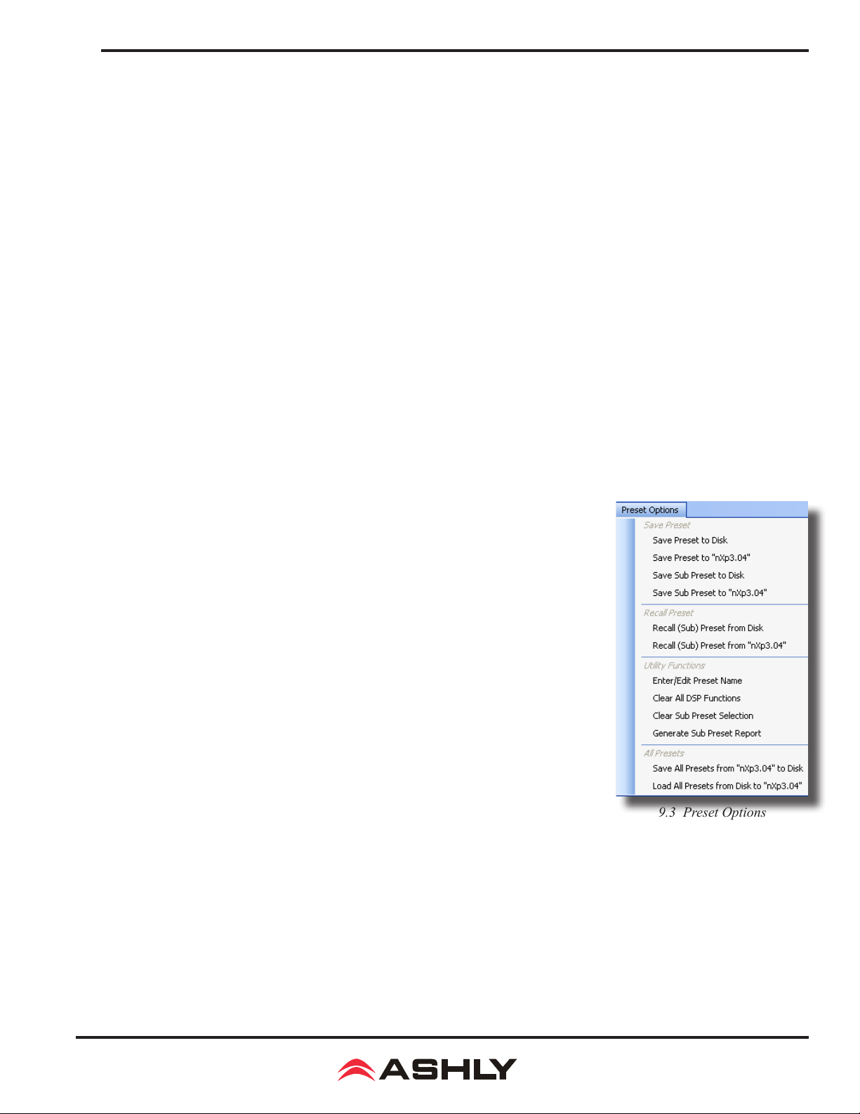
9.3 nX Preset Options Menu
The Preset Options menu in the main device window allows user-dened setups to be named, saved
to, and recalled from the amplier or a networked computer. Several other utility functions are available as well. Presets are a snapshot of all current settings on a given amplier.
nX ampliers can store up to 31 internal presets, each preset storing control data for all channels
and audio functions. Preset names must be 20 characters or less. Changes to an individual preset
can be saved to the amplier using <Save Preset To "nX***">, or saved to the PC using <Save
PresetTo Disk>. Individual preset les use the extension (*.pne).
9.3a Sub Presets: Instead of saving or recalling an entire preset affecting all device func-
tions, a sub-preset affecting only a user dened sub-set of DSP functions can be created. To
create a sub-preset, rst check the box labeled <Selected for Sub-Presets> in all DSP control
blocks to be associated with this sub preset, then under the preset options menu click <Save
Sub Preset to Disk> or <Save Sub Preset to
A preset or sub preset can be loaded to the amplier by one of the following methods:
1) Use Proteane software on a PC connected to the network to recall les saved on either
the PC or on the amplier.
2) Use contact closures to load presets 1-4 from memory by wiring switches to the rear panel
contact closure connector.
3) Use an Ashly WR-5 or neWR-5 remote control.
4) Use the event scheduler.
"nX***"
>.
9.3 Preset Options
Note: A full preset recall event will overwrite any unsaved changes, so be sure the current conguration is saved before continuing
or any changes will be lost. The amplier always loads the last working settings on power-up, to preserve any changes should
the power be inadvertently turned off prior to saving a preset. Caution: A new preset may have dramatically different settings
capable of damaging sound system components, so be careful not to recall the wrong preset while the system is on.
19
Page 20
Operating Manual - nX, nXe, and nXp Power Ampliers
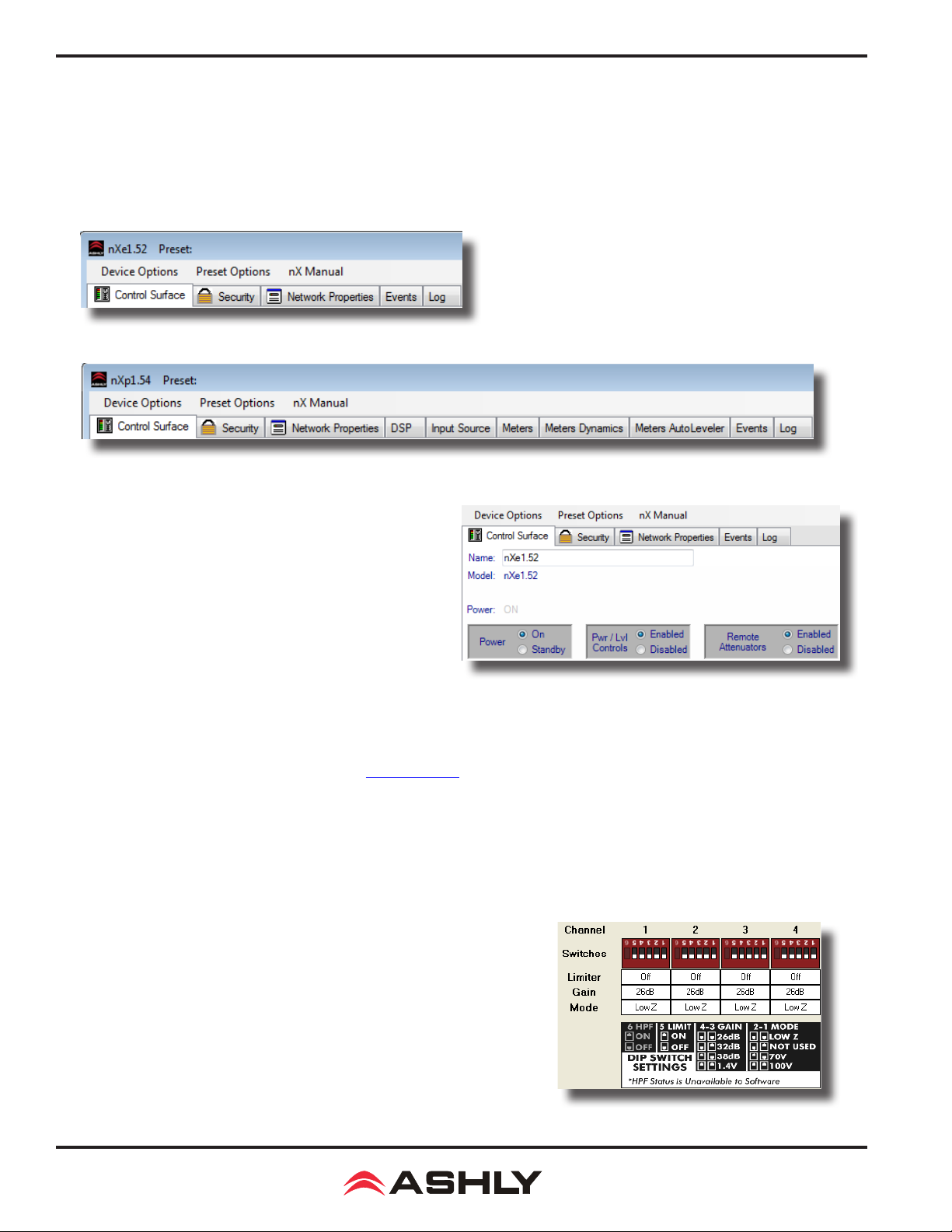
9.4 Device Control Tabs
The following device control tabs are available for nXe and nXp models.
nXe series ampliers include Control Surface, Security, Network Properties, Event Scheduler, and Fault Log, plus optional
Cobranet if installed.
nXp series ampliers add DSP, Input Source, Meters, Meter Dynamics, Meters AutoLeveler, and CobraNet if installed.
nXe Series Control Tabs
nXp Series Control Tabs
9.4a Software Control Surface - Global
The control surface is the main user interface for the amplier
section. DSP functions, if available, are managed from the DSP
tab. The following amplier functions are available in the control
panel:
Name - The user dened name for this specic amplier.
Up to 20 characters can be used.
Model - The model of amplier being addressed
Power - Shows power status as On, Off, or Standby.
Power On/Standby - This
controlled by a rear panel contact closure or by the event scheduler.
shows power status and allows the user to set power to standby from software. Standby can also be
The front panel power switch blinks when in standby.
Power/Level Control Enable/Disable - This disables both the front panel power switch and all level controls, xing the
value of all level controls at maximum (fully on) regardless of their position.
surface will always reect the physical position of the amplier's front panel attenuators, even when they are disabled and not attenuating
the signal.
Remote Attenuator Enable/Disable - Disables all "Remote DC Level Control" Euroblock connectors on back panel
Internal Amplier Ambient - This indicates the internal ambient temperature
of the amplier.
9.4a - Control Surface Global Functions
Note that the software attenuators shown on the control
DIP Switch Settings - Every amplier channel has a six position rear-panel
DIP switch for setting HPF, Limiter, Gain, and Output Mode. The HPF status is
unavailable to software and is not displayed. Current DIP switch positions for
Limiter, Gain, and Mode are always shown on the main software control surface.
20
9.4a - Control Surface DIP Switch Settings
Page 21
Operating Manual - nX, nXe, and nXp Power Ampliers
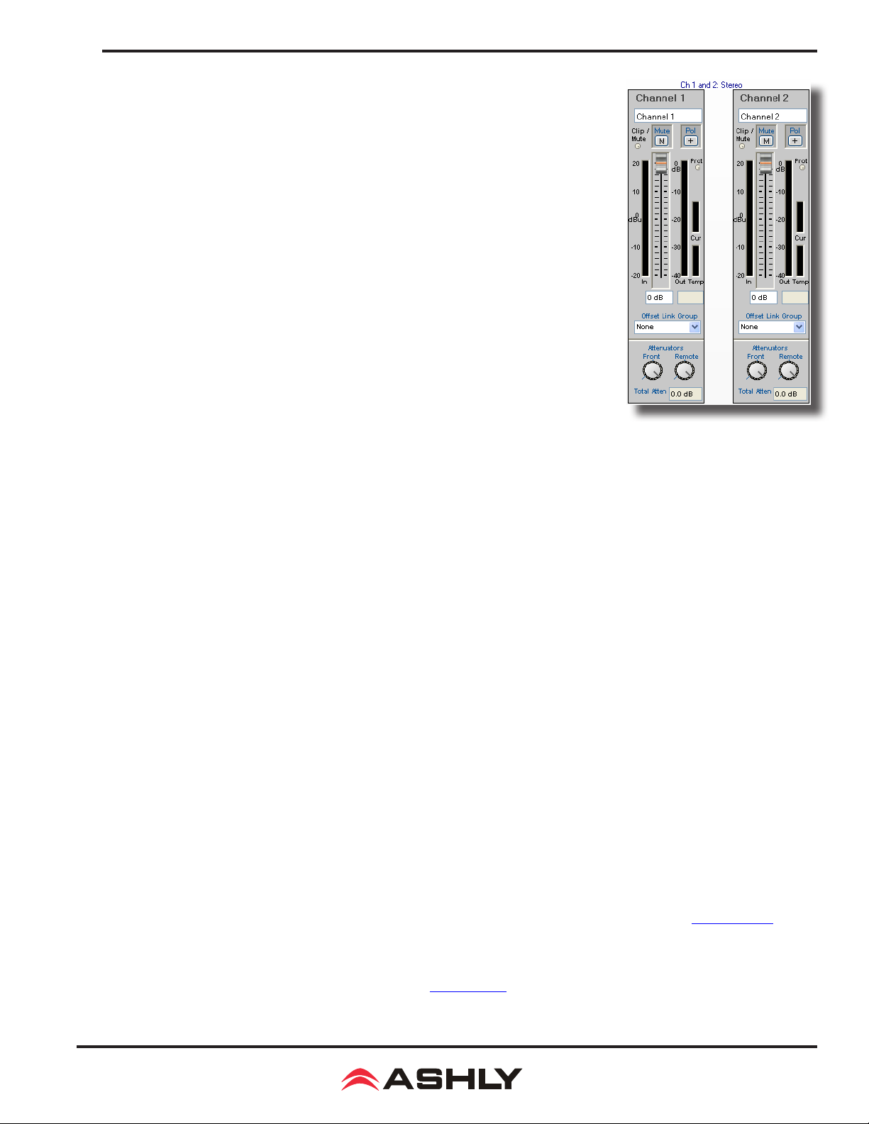
9.4a (continued) Software Control Surface - Channel
Stereo/Bridged Status - This shows if a channel pair is in stereo or bridge mode as set by
back panel switch. In bridge mode, input signal is automatically taken from the odd channel input and inverted, then sent to the even channel. The even channel controls become
disabled. Note that in bridge mode, the even channel software attenuators will still reect
the physical position of the amplier's front panel attenuators, even though they are removed
from control of bridged signal.
Channel Name - This user dened text box names the amplier output channel. Up to 20
characters can be used.
Clip/Mute LED - This LED shows when the amplier output is either muted or clipping.
Clipping is indicated when the output level is 1dB below the output power supply rails, and
accurately tracks AC line voltage sags. This LED shows the same status as the front panel
clip/mute LED.
Mute Button - This button mutes the output channel. Output mute can also be controlled
by the event scheduler, WR-5, or neWR-5 remotes.
Polarity Button (Pol) - This button inverts the polarity of the output channel signal.
Input Meter - This meter indicates the pre-fader amplier input level in dBu.
9.4a - Control Surface
Channel Functions
Main Output Channel Fader - This controls the output attenuation. Output attenuation
below -40dB mutes the output.
Output Meter - This indicates the amplier output level in dB below full rated output.
Protect Indicator (Prot) - These indicate an overtemperature, overpower, or overvoltage fault on individual channels.
Current Meter (Cur) - The Current LED shows that the amplier is delivering current to a load, and is useful to determine
if a speaker load is open or shorted.
Temperature Meter (Temp) - The temperature meter and text box shows the current operating temperature of the output
devices for each channel. Excess of 100°C will trigger overtemperature protection.
Offset Link Group and Offset Faders - A group of output channels can be linked together to attenuate the group as a
whole without changing the relative levels of each channel. If a channel is assigned to one of the 16 offset link groups, a colored
triangle marker appears on the left side of the main fader graticule for secondary level control of all channels in that group. Left
click and drag this marker up or down to adjust the link group level. The actual main output channel faders can not be linked to
a group. Note that more than 40dB of cumulative channel attenuation causes the channel to mute.
In addition to the control surface offset link group attenuator control (not the main fader), most DSP functions have a link group
check box in their work window to assign a specic DSP parameter to one of 16 link groups if desired. Link groups can be
renamed by clicking on any group name and entering the new name.
Attenuators - These two dials indicate the physical position of hardware level controls on either the amp front panel or the
remote DC level control. Note that these will display the position of attenuators even when they are disabled.
Total Attenuation - This indicates the total amount of attenuation being applied to the channel. It is the sum of the following
attenuation points: control surface fader, offset link group attenuation, front panel level control, and remote attenuator.
Note: The maximum dynamic range of the amplier is achieved when the amplier’s attenuation is set to the optimal value. The
amplier’s front panel attenuators follow the DSP section but precede the power amplier section (see block diagram). Thus,
the optimal setting for maximum dynamic range is determined by subtracting the amplier's input sensitivity from the maximum input signal of +20dBu. For example, when the back panel Gain DIP Switch is set for gain of 1.4V, the input sensitivity
is +5.1dBu (1.4Vrms = +5.1dBu). Subtract +5.1dBu from +20dBu, and that results in 14.9dB attenuation required for optimal
dynamic range. For other input sensitivity values, see the specications section.
21
Page 22
Operating Manual - nX, nXe, and nXp Power Ampliers
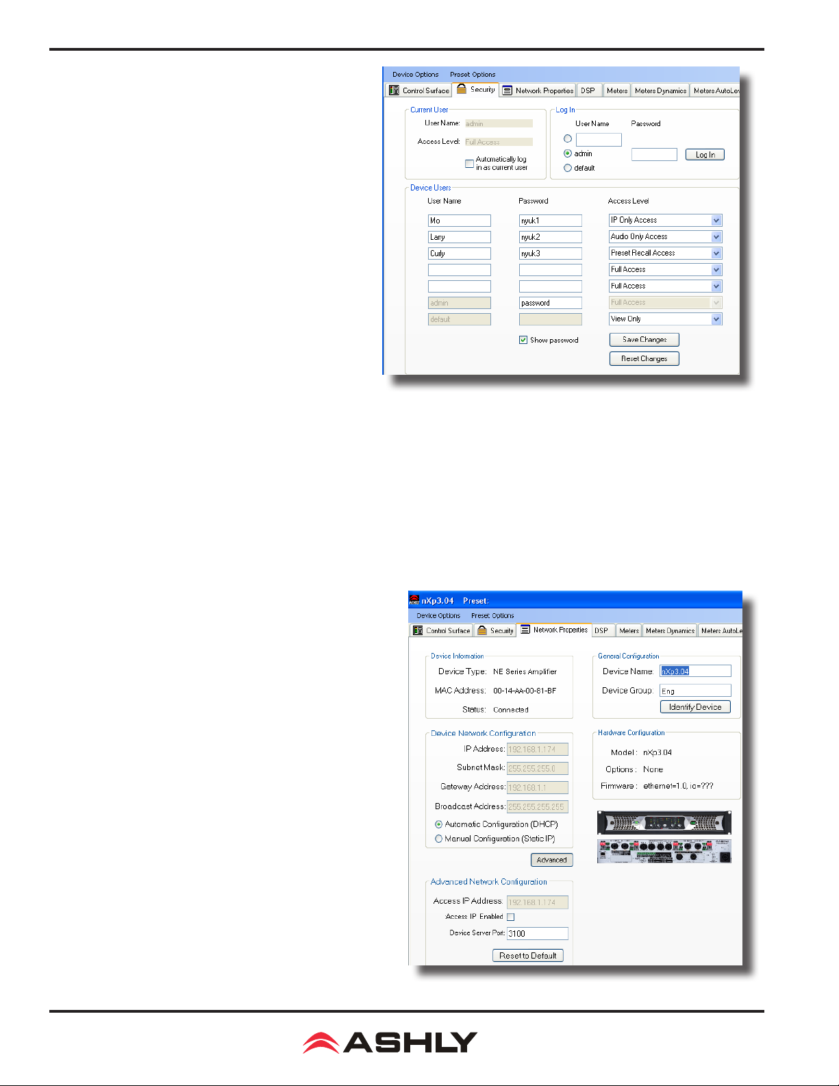
9.4b Security Tab
Ashly nXe and nXp ampliers have multi-user/multi-level
security capability. When security levels are dened, a person
must have a User Name, Password, and sufcient access
level to make changes. Seven different users are supported;
a Default user, an Admin user, and ve additional custom
named users. All security information is stored in the amplier, not in presets. Passwords are case sensitive.
The Security tab has three sections, the [Current User] section that shows the currently logged in user and their access
level, the [Log-In] section where a person logs in as Default,
Admin, or custom user name, and the[Device Users] section
where new user names and passwords are entered and where
access levels are assigned for each user name.
Default -
not be renamed, and never requires a password. The factory
setting for the Default user is to allow full access. Anyone can
log in as the Default user, so it's user access level should be
set low, typically View Only, once security settings have been
implemented. To log in as Default user, click the [Default] checkbox in the Log In section and then click the Log In button.
The Default user is the base level of access, can-
9.4a - Security Tab
Admin - The Admin user is for the highest administrative person, cannot be renamed, and always has full access. Any changes
to the Admin password are made in the Device Users section and must be saved by clicking on the [Save Changes] button. To
log in as Admin in the Log In section, click the [Admin] checkbox, enter the password if one is assigned, and click the Log In
button. Only the Admin, or anyone else with full access, has the right to show passwords, save changes, reset changes, or edit
user names, passwords, and access levels. A factory reset will erase all user names and passwords in the amplier.
Other User Names - Up to ve custom User Names can be entered in the Device Users section along with passwords and
access levels.
Access Levels - On ampliers without DSP, access levels
are View Only, Audio Only, IP Only, and Full Access. With
DSP, additional access levels include Audio Parameter Access, Preset Recall Access, DSP Input Channel Access, and
DSP Output Channel Access.
9.4c Network Properties Tab
In this tab, device information includes device type, MAC
address, and network connect status. Device network conguration can be set to automatic DHCP (recommended) or
Manual Static IP. Advanced Network Conguration allows
the user to bypass corporate rewalls and assign a specic
port for remote setup and monitoring.
The user can visually identify the amplier on a network
by clicking the "Identify Device" button, which lights the
COM LED on the amplier's front panel for two seconds.
The amplier's rmware revision is shown in the hardware
conguration section as well. From time to time Ashly
may post updated rmware on our website which can be
downloaded and then ash reprogrammed to the amplier.
Flash reprogram is found in the device options menu when
connected to a live amplier.
22
9.4c - Network Properties Tab
Page 23
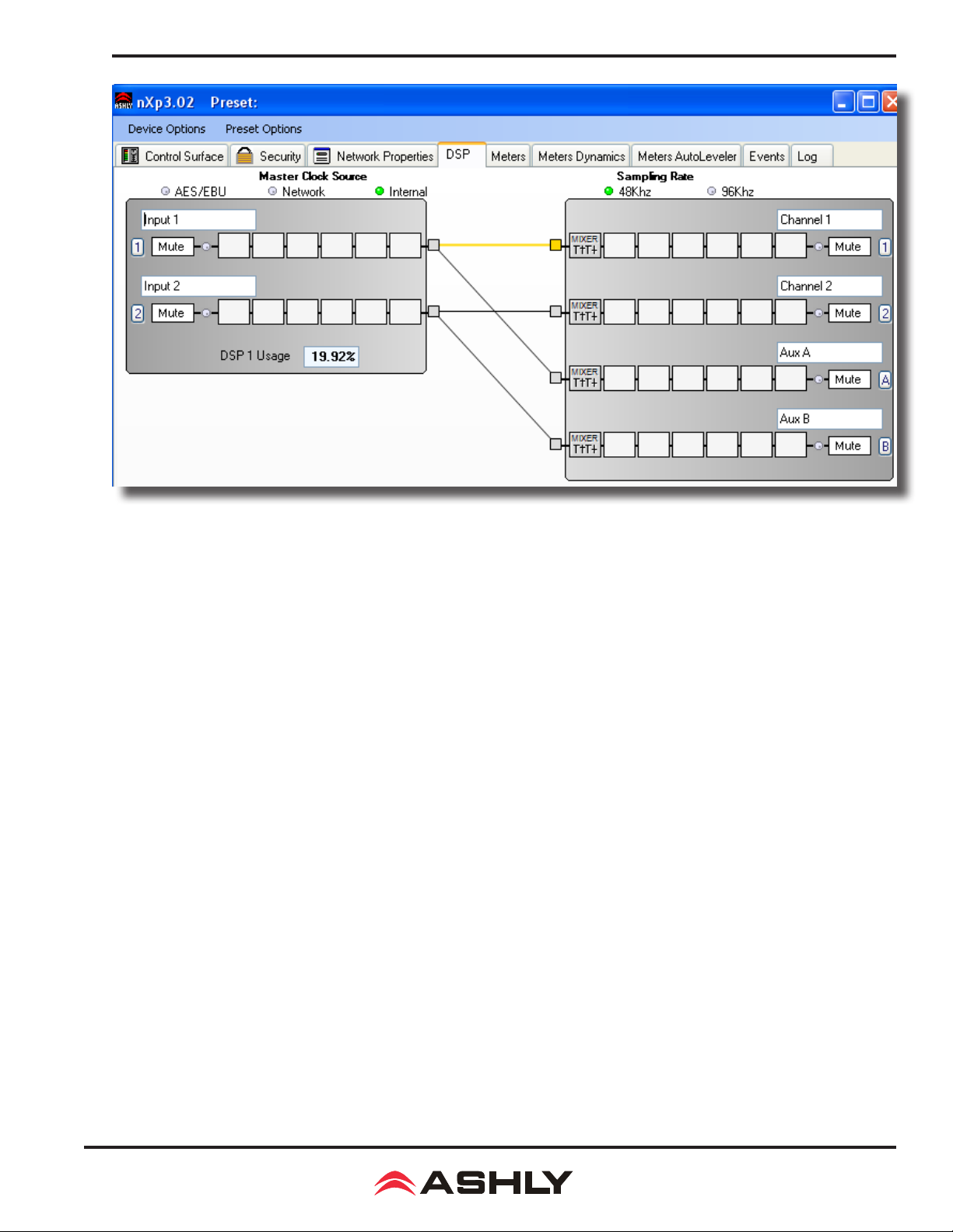
Operating Manual - nX, nXe, and nXp Power Ampliers
9.4d DSP Control Tab
All signal processing is done in the DSP control tab, with separate input and output sections and a cross-linking matrix mixer
between. From left to right, each channel in the DSP tab includes the following features:
Input/Output Channel Number - Click on this to use each channel's Clear, Copy/Paste, Link, and Sub Preset functions.
Input/Output Channel Name - The user can name each input or output channel.
Input/Output Mute Button -
Input/Output LED - Shows signal present or clipping for that DSP input or output channel.
Pluggable DSP Blocks -
block to select one DSP function from the drop-down list. Left-click on the placed DSP function to adjust it's parameters, or right-click
on it to Bypass, Select for Sub-Preset, Copy/Paste to another similar block, or Delete. Total DSP usage is indicated as a percentage
at the bottom of each input section in the DSP tab. Increasing the number and complexity of applied DSP tools increases the DSP
usage. Total DSP usage cannot exceed 100%. All DSP functions are listed below, with details on the following pages.
1) Dynamics controls - Brick Wall Limiter, Compressor, Autoleveler, Ducker, and Noise Gate. Ambient Noise Compensation
is available on outputs only.
2) Gain functions - Gain, Gain with VCA, RD-8C Remote Control Gain, neWR-5 Remote Control Gain
3) Equalization -
31 Band Graphic EQ, 10/6/4/2-Band Parametric EQ, Feedback Suppressor (input), FIR lter (output)
4) Crossover functions - Four-Way, Three-Way, and Two-Way Crossovers are available on outputs only. HPF and LPF lters
are available on both inputs and outputs.
Mutes the input or output. Note that only the output mute lights the front panel Mute LED.
Six pluggable DSP blocks are available for each input and output. To use, right-click on an empty DSP
5) Delay - At 48kHz, Maximum Speaker Delay is 21mS, and maximum Delay is 682mS. At 96kHz, they are 10mS and 341ms
respectively.
6) Metering - -60dBu to +20dBu display
7) Signal Generator - Pink noise, White Noise, Sine Wave
23
Page 24
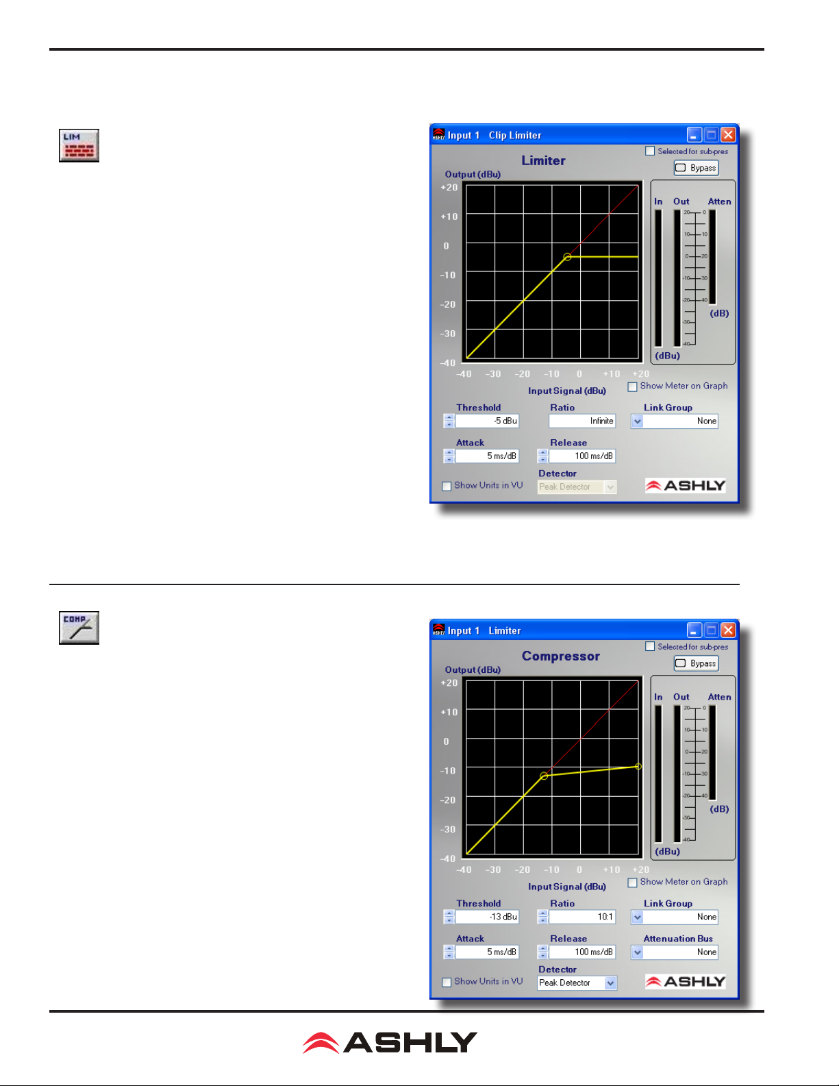
Operating Manual - nX, nXe, and nXp Power Ampliers
Pluggable DSP Block Descriptions
1) Dynamics Controls
Clip (Brick Wall) Limiter
The Clip Limiter is a compressor with xed ratio (innite). It allows
for user-adjustable threshold, attack time and release time. It also
allows for assignment to a Link Group to link the parameters of this
block with limiters on other channels. For a full-featured compressor/
limiter, refer to the Compressor.
Parameters:
Threshold - The signal level at which the Limiter begins to attenuate
the signal. (+20 to -20 dBu).
Ratio - The amount of attenuation to the signal above the threshold
point. Fixed at innite, meaning no signal beyond this level.
Attack Time - The rate (in ms/dB) at which the Limiter attenuates
the input signal, once the signal reaches threshold.
Release Time - The rate (in ms/dB) at which the attenuation will
return to normal, once the signal falls below threshold.
Link Group - Group to which all parameters are assigned, for simultaneous adjustment to multiple Limiters
Show Meter On Graph - Overlays the input/output level meters on
the Limiter graphical display.
Detector - Fixed at Peak.
Compressor
The Compressor function is a full featured Compressor/Limiter. It
allows for user-adjustable Threshold, Ratio, Attack Time, Release
Time and Detector type. The Compressor also allows for assignment
to a Link Group to facilitate adjustment of multiple Compressor/
Limiters simultaneously. A separate Attenuation Bus assignment is
provided to allow multiple limiters to force their gain reductions to
track each other, ie stereo signals. For simple peak limiting, the Brick
Wall Limiter can also be used.
Parameters:
Threshold - The signal level at which the Compressor begins to attenuate the signal. (+20 to -20 dBu).
Ratio - The amount of attenuation to the signal above the Threshold
point. Range is 1.2:1 to innite.
Attack Time - The rate (in ms/dB) at which the Compressor attenuates the input signal, once the signal reaches Threshold.
24
Page 25
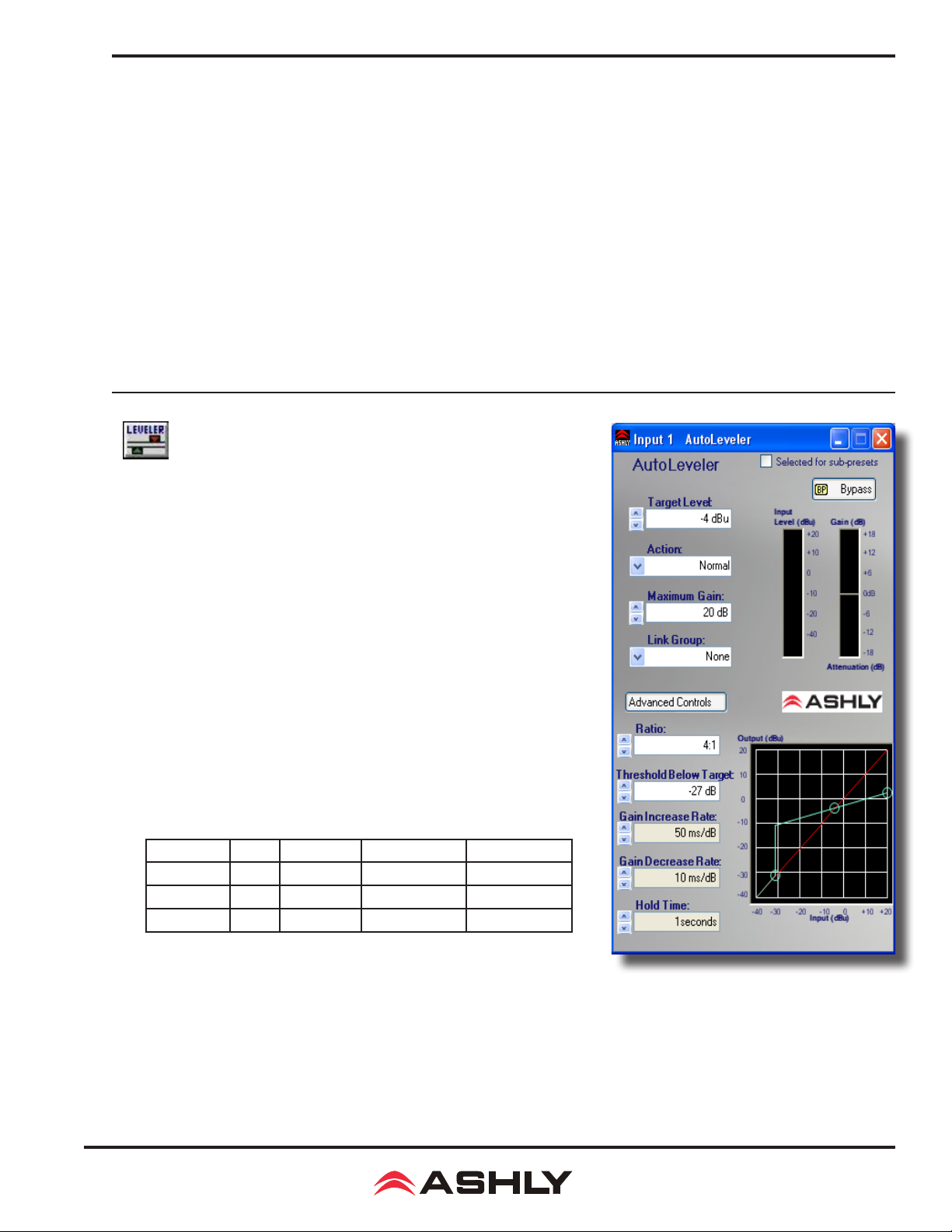
Operating Manual - nX, nXe, and nXp Power Ampliers
Release Time - The rate (in ms/dB) at which the Compressor attenuation will return to normal, once the signal falls below
Threshold.
Link Group - Group to which all parameters are assigned, to facilitate simultaneous adjustment to multiple Compressors in
the system.
Attenuation Bus: All Compressors assigned to the same Attenuation Bus will apply the largest amount of attenuation on any
of the assigned Compressors. This can be used to facilitate "stereo" (or similar) operation of multiple Compressors.
Show Meter On Graph - Overlays the Input/Output level meters on the graphical display.
Detector - Selects between PEAK and AVERAGE operation of the Detector (see below).
Peak Detector - Setting the detector to Peak means that the peak level of a signal is used to trigger the Compressor. In Peak
detect mode, Attack and Release times are both adjustable
Average Detector -
Instead of separate Attack and Release controls, the Average Rate controls the speed at which the compressor functions.
Setting the detector to Average means that the average level of a signal is used to trigger the Compressor.
Autoleveler
The Auto Leveler is a dynamics processor used to automatically boost or cut a
signal to a user-dened target level. The Target Level is the primary setting in
the Autoleveler, as it determines the constant level to which an input is boost or
cut. The Autoleveler can be used in situations such as speech re-enforcement,
where an unknown source level needs to be maintained at a specic output level.
For example, a podium microphone where different speakers will be presenting
may have an auto-leveler applied to ensure that strong or soft speakers' voices are
amplied appropriately. The controls for the auto leveler are split into two categories, Basic and Advanced. It is recommended you start with the basic controls,
and if ne tuning is required, use the advanced controls. Warning: Depending
on the settings, it is possible to apply up to 27dB of gain with the auto leveler.
Basic Parameters:
Target Level - The desired continuous output level of the signal.
Action - Sets the Ratio, Hold Time, and Gain Change Rates (see below for
denitions). These settings are general starting points for how the auto leveler
should behave. Action can also be user dened under Advanced Controls, with
three drag points available for a more visual adjustment.
Action Ratio Hold Time Gain Increase Gain Decrease
Aggressive 10:1 0 Seconds 20 ms/dB 5 ms/dB
Normal 4:1 1 Second 50 ms/dB 10 ms/dB
Gentle 2:1 2 Seconds 100 ms/dB 20 ms/dB
Maximum Gain - This is the total amount of gain the auto leveler may apply before it stops affecting the signal. Maximum
Gain controls the Threshold Below Target using the following formula:
Threshold Below Target = Max Gain ÷ ( ( 1 ÷ ratio) - 1)
Advanced Parameters: (see image on previous page)
25
Page 26
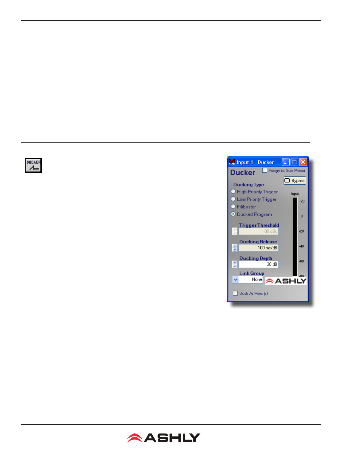
Operating Manual - nX, nXe, and nXp Power Ampliers
Threshold Below Target - Determines the relative input signal level above which the Autoleveler increases gain, below which
no action is taken.
Ratio - This is the ratio of the input level change in dB to output level change in dB. It determines the degree of boost or cut
applied to a signal to maintain the target level. The higher the ratio, the closer the signal (above threshold) will approach the
target level. However, a higher level will also increase how aggressive the Autoleveler will maintain that gain.
Gain Change Rate - Prevents sudden, choppy-sounding level changes to an input signal having a wide dynamic range.
Hold Time - This is the time after the input signal falls below the threshold during which the Autoleveler's gain is held con-
stant before it returns to unity gain. Hold Time is used in conjunction with gain change rate to arrive at a natural-sounding auto
leveler action.
Both the Advanced and Basic control views have a visible meter bar. It shows the gain or attenuation applied by the auto leveler
in 1 dB steps.
Ducker
The Ducker is used to attenuate the level of selected channels when one or more "Trigger"
channels has signal preset. This is typically used in paging applications where a common
input signal such as background music needs to be attenuated when signal is applied to a
specic channel (e.g., a paging microphone).
Parameters
Ducker Type - Available types are High and Low Priority Trigger, Filibuster, and Ducked
Program.
Trigger Threshold - The signal level on a trigger channel at which point all ducked
program channels are attenuated.
Ducking Release - This determines the time the ducked program stays attenuated after
the trigger input signal has fallen below its threshold.
Ducking Depth - Determines how much attenuation is applied to input channels set for
ducked mode.
Duck At Mixer(s) - Disables any attenuation being applied to the input and enables the
ability for each output channel's matrix mixer to apply the attenuation.
Ducker Types
High Priority Trigger - When signal is present on this channel, all channels set to "Ducked Program", "Low Priority Trigger"
and "Filibuster", attenuated to -Inf. (Muted).
Low Priority Trigger - When signal is present on this channel, all channels set to "Ducked Program" will be attenuated by the
depth specied on that channel. All channels also set to libuster will be attenuated to -Inf. (Mute).
Filibuster - When signal is present on this channel, all channels set to "Ducked Program" will be attenuated by the depth specied on that channel. All channels also set to Filibuster are attenuated to -Inf. Only one Filibuster channel is allowed to be above
the threshold at any given time, the rest are fully attenuated. The libuster input does not allow other signals to return to normal
until half a second after it has fallen below its threshold.
Ducked Program - Sufcient signal present on any Trigger Channel will cause this channel to be attenuated by the specied depth.
26
Page 27
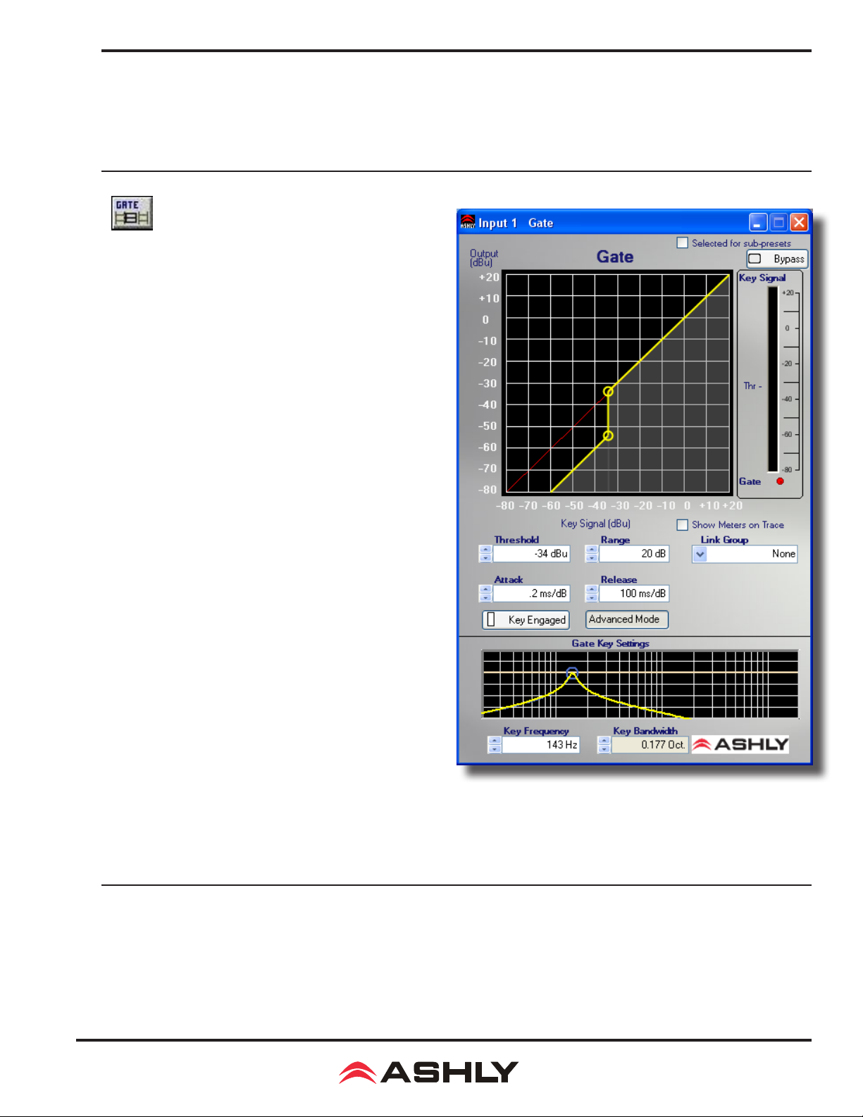
Operating Manual - nX, nXe, and nXp Power Ampliers
Ducking At Mixer(s)
This feature is particularly useful when setting up multiple zones where only some of the output channels should be ducked
(e.g. restaurants, courtrooms, etc.). When this feature is selected, each Matrix Mixer is allowed to enable or disable the Ducking on that particular output.
Noise Gate
A Noise Gate can be used to minimize unwanted, low level
signals from an individual input. Threshold is the level above
which an input signal will pass through, below which its signal
is attenuated by the Range value. Attack and Release control the
time characteristics of the gating action. Attack sets the amount
of time used to ramp the gain to unity. Release sets the time
required to attenuate the signal. The Gate may be assigned to
a Link Group to link its parameters with other Gates.
Parameters:
Threshold - The minimum signal level required to "open" the
gate and allow signal to pass through, available as text box or
as the top drag node on the graph.
Range - The amount of attenuation applied to the unwanted
signal when it remains below Threshold, sometimes referred
to as "oor". It is available as text box or as the bottom drag
node on the graph.
Attack - The rate at which the gate rises to unity gain after the
signal has reached Threshold.
Release - The rate at which the gate applies attenuation to the
signal after it falls below Threshold.
Advanced Mode Parameters:
Advanced Mode allows the user to specify a Key lter for the
gate. The key lter does not EQ the signal passing though the
gate, but rather allows the gate threshold to respond only to a
frequency band within the signal as determined by the lter. The
Key lter is a band-pass lter with selectable center frequency
and bandwidth. The Key lter is only engaged when the Key Engaged button is clicked.
Key Frequency - This is the center frequency of the key lter, use text box or drag the frequency node left or right.
Key Bandwidth - This is the bandwidth of the key lter, use the text box or right-click-drag the node left or right..
27
Page 28
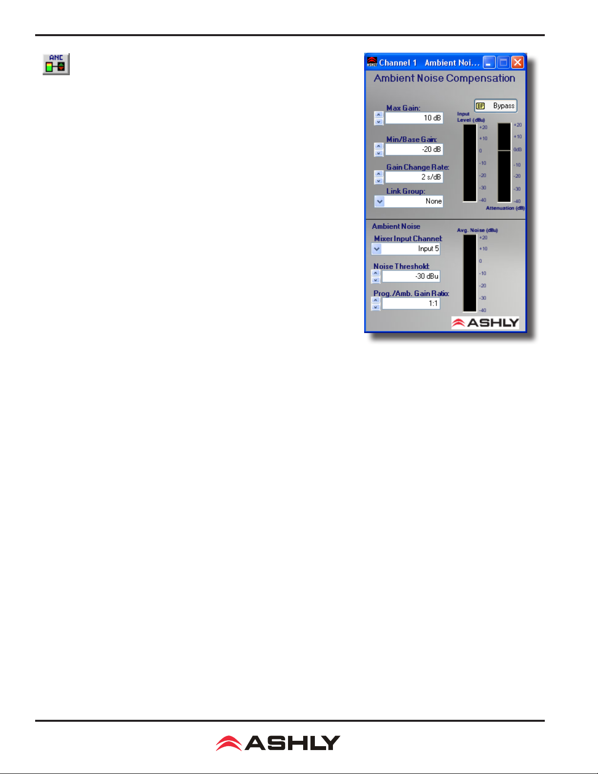
Operating Manual - nX, nXe, and nXp Power Ampliers
Ambient Noise Compensation (output channels only)
Ambient Noise Compensation (ANC) is an automatic output level control that uses
a microphone to monitor background noise in a specic zone, then adjusts the output level to that zone accordingly in order to maximize intelligibility. One amplier
input channel must be dedicated to the sensing microphone and cannot be used for
other inputs.
nX ampliers do not have mic preamps, so an external mic preamp is required. The
mic preamp output is then connected into any input on the nX amplier other than
the program audio channel in which the ANC function is engaged on. The ambient
noise signal is then processed similar to a slow-responding SPL meter which is
then used as the control signal for the automatic level control of the program audio/
paging signal.
The ambient noise sensing microphone doesn't need to be a high-quality microphone
because it is only used to pick-up the overall noise level in the room and is not used
for the direct program audio or paging. The placement location of this noise-sensing
microphone is very important for the ambient noise compensation function to work
well. A unidirectional microphone pointed toward the noise sources and away from
the sound system speakers works best.
ANC Meters and Controls
Input Level Meter - The input level of the program audio before ANC gain/attenuation is applied.
Attenuation Meter - The gain/attenuation automatically applied to the program audio by the ANC function.
Max Gain - Sets the maximum gain that you allow the ANC to apply to the program audio. A typical starting value is 10 dB.
Min/Base Gain - Sets the minimum gain that you allow the ANC to apply to the program audio. A typical starting value is -20
dB. This also sets the starting gain value once the noise exceeds the threshold. The minimum gain is +1dB.
Gain Change Rate - The rate at which the ANC will change the gain as measured in seconds per dB. A typical starting value
is 2 seconds/dB.
Link Group - The channel group assignment for linking multiple channels parameters. Use this feature to link stereo program
audio channels to track each other in gain changes in response to ambient noise change.
Average Noise Meter - The level of the ambient noise signal at the point where it enters the matrix mixer and the ANC function.
Mixer Input Channel - The input channel selected for the ambient noise sensing microphone. The microphone signal is taken
at the point where it enters the matrix mixer, after any input signal path processing.
Noise Threshold - The noise-sensing signal level above which you desire the ANC to start to increase the program audio gain
above the Min Gain. A typical starting value is -30 dBFS. Keep in mind that any changes to the gain of the noise-sensing microphone will affect the setting of the Noise Threshold control.
Program/Ambient Gain Ratio - The ratio of dB increase in program level for every 1 dB increase in ambient noise level. A
typical starting value is 1.0 which means that for every 1 dB increase in ambient noise, the ANC will automatically increase
the gain of the program audio by 1 dB.
28
Page 29
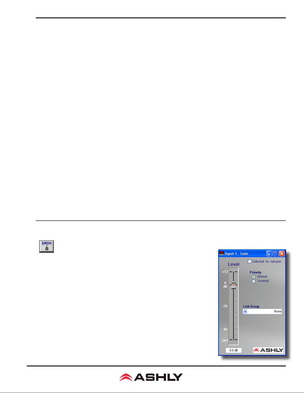
Operating Manual - nX, nXe, and nXp Power Ampliers
ANC Setup Procedure
1) In the control software, assign the ANC function to the channel to be used for background music or voice paging (program
audio). Set the ANC controls to the "typical" settings described above, which is also the default settings of a new ANC function
when it is rst placed in the signal processing block.
2) Open the ANC control window and select the noise-sensing microphone input channel in the drop-down box labeled Mixer
Input Channel.
3) Physically locate the noise-sensing microphone in the room by pointing it toward the noise sources such as groups of people
talking, HVAC equipment etc., yet pointed away from the sound system speakers.
4) Add microphone preamp gain (external preamp) and level control functions (software) on the noise-sensing microphone signal
path before the matrix mixer and adjust the microphone gain so that you can see the ambient noise input level meter start to show
a level when the room noise starts to increase. To adjust the ANC controls for good-sounding operation without people present,
a pink noise source or even a boom box can be used placed near the expected noise location to simulate the expected noise.
5) Adjust the ANC's Noise Threshold control to the ambient noise input level at which you would like the program audio gain
to start to increase. Increase the room noise source so that you see the ambient noise input level meter rise above your Noise
Threshold setting. You should see the Program Audio Gain meter slowly rise above the Min Gain setting.
6) Slowly increase the noise source and adjust the Program/Ambient Gain Ratio for the desired amount of noise compensation.
7) Continue to increase the noise source to the highest level you would expect. Adjust the Max Gain to a level which limits the
maximum gain which the ANC applies to the program audio so that it will not become too loud or clip.
8) The Gain Change Rate can be adjusted according to how fast you would like the gain changes to take place in response to
changes in ambient noise.
9) Be aware that an improperly setup ANC can result in runaway gain where the program audio is picked-up by the noise-sensing
microphone as background noise. The result is not necessarily feedback squeals, but the gain of the program audio could ramp
up to the Max Gain value even with no ambient room noise. Usually the best remedy for this problem is to locate the noisesensing microphone closer to the expected noise sources and further away from the sound system speakers. Sometimes a bafe
may be helpful, located between the speaker and microphone to block direct sound pickup. Also, the ANC Program/Ambient
Gain Ratio can be lowered to reduce the susceptibility to gain runaway.
2) Gain Functions
Gain
The Gain block allows the user to modify a signal's level by either applying gain or attenuation. The Polarity of the signal may also be inverted. The Level control allows for gain
adjustment between +12db and -50dB and OFF. The LEVEL fader can be adjusted in 0.5dB
increments. Finer adjustment (0.1 dB increments) may be made by typing in the value into
the provided text box below the fader.
The Gain block may be Linked with any other Gain block via Proteane Software. This will
force all parameters (level and polarity) to be the same across the Linked blocks. Note that
changes to a Linked Gain block do not affect a VCA Gain block.
For a more powerful linking of gains consider using the Gain with VCA block.
Parameters
Level - Off, -50dB to +12dB in 0.1dB increments
Polarity - Normal or Inverted.
29
Page 30
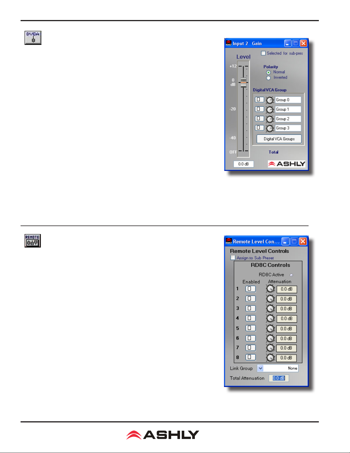
Operating Manual - nX, nXe, and nXp Power Ampliers
Gain with VCA
The Gain w/ VCA block allows the user to modify a signal's level by either applying gain
or attenuation. The Polarity of the signal may also be inverted. The Level control allows
for gain adjustment between +12db and -50dB as well as OFF. The Level fader can be
adjusted in 0.5 dB increments. Finer adjustment (0.1 dB increments) may be made by
typing in the value into the provided text box below the fader.
Additionally, the Gain can be assigned to a subgroup using the Digital VCA Group. This
allows a single "Master" fader to adjust multiple gains. Note that unlike using Linking, the
Digital VCA Group does not change the position of the Level fader. Rather, the "virtual"
fader is created by the Digital VCA Group. As the Digital VCA Group "Master" fader is
moved, the amount of gain/attenuation is added to the Level shown on the Gain w/ VCA
fader. This works in a similar fashion to a "VCA Subgroup" on a mixing console. Note
that a single Gain w/ VCA block can be assigned to up to 4 Digital VCA Groups, thereby
allowing more complex congurations.
Parameters
Level - Off, -50dB to +12dB in .1dB increments.
Polarity - Normal or Inverted.
Digital VCA Group Enabled - Selecting this button enables each corresponding Digital VCA Group.
Digital VCA Groups - Selecting this will open the VCA Groups Master Faders window.
Total - This indicator shows the total gain/attenuation applied to the channel. It is the sum of the gain of the Level fader plus
the gain applied by each of the enabled VCA Groups.
RD-8C Remote Control Gain
Remote Gain allows the user to choose where Ashly's RD-8C will apply gain to a signal
path (WR5s are handled by the WR5 Gain Block). When the remote is assigned to a
channel, it applies gain/attenuation within the remote gain block, allowing the other gain
blocks to remain unaffected by the remotes. This allows for more complex setups, i.e.
the system has a specied maximum gain/attenuation (when the remotes are all set to 0),
but may not be the maximum for the unit.
RD8C Controls
The RD8C Controls allows the user to see the current status of the RD8C, and assign
faders to a channel. Any fader may be arbitrarily assigned to any DSP channel or multiple
DSP channels. When "Enabled" is checked (Green) for a particular RD8C Fader, then
that fader's attenuation is applied via the remote gain block. The current attenuation for
each fader is also displayed for ease of setup and knowledge of how a fader will affect
the channel. The RD8C Active LED is also available. This indicates whether or not a
RD8C has been or is being used with this device.
Total Attenuation - The total attenuation is displayed. This is the total amount of attenuation applied by the remote gain block.
Link Group - It is possible to link the remote gain block to other remote gain blocks.
When these remote gain blocks are linked, their WR5 attenuation and RD8C assignments
will track. This allows for room-combining where the WR5's gains should track each other.
30
Page 31
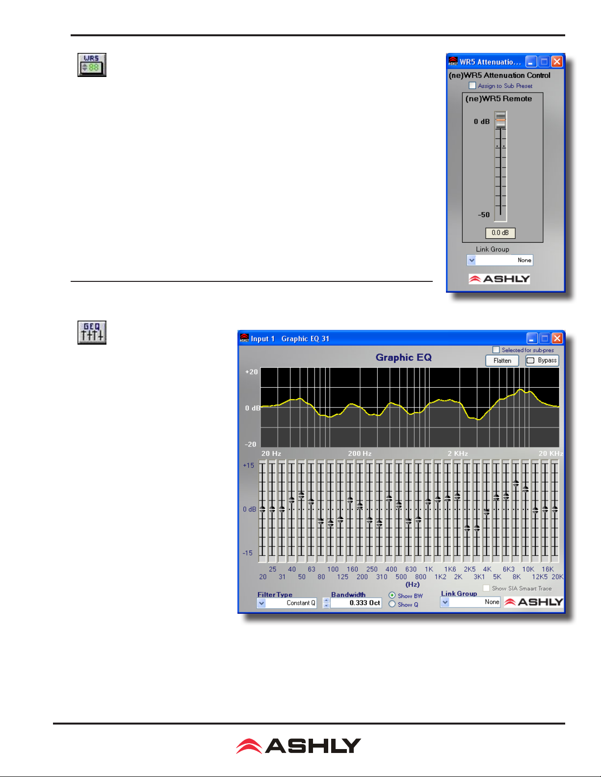
Operating Manual - nX, nXe, and nXp Power Ampliers
WR-5, neWR-5 Remote Control Gain
The WR5/neWR5 Gain block is the DSP block where channel gain adjustments are made via
the WR5 or ne-WR5 remote. This block is nearly identical to the standard gain block except
that it is also controllable via the WR5 or ne-WR5 remote and does not have polarity inversion.
This block may be linked for room-combining situations.
3) Equalization
Graphic Equalizer
The graphic equalizer offers 31 standard
ISO center frequency controls with
Constant Q or Proportional Q lters, as
well as adjustable lter bandwidth. The
Flatten button returns all lters to nominal. Individual lters can be returned to
nominal by pressing <Ctrl + Click> on
the fader knob. A course EQ curve can be
drawn quickly by left-clicking and dragging across the EQ frequency response
display. Multiple graphic equalizers may
be assigned to a Link Group so that their
controls will track.
Parameters
Filter Type - This selects Proportional Q
or Constant Q (default) lters. Constant
Q lters have consistent Q/Bandwidth
regardless of the amount of boost or cut.
Proportional Q lters get narrower with
increasing boost/cut. Differences in lter
shapes can be observed on the frequency
response display.
Bandwidth - This sets the Bandwidth of the lters, from 1/4 octave to 1/2 octave (before Proportional Adjustment). The default
bandwidth is 1/3 octave.
Link Group - Link Group to which this block is assigned, useful for stereo signals.
Faders - Graphic representation of 31 lter amplitude controls.
31
Page 32
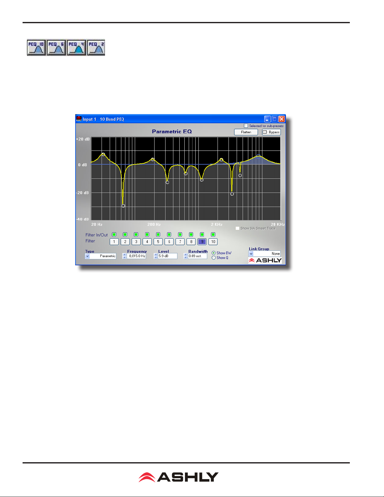
Operating Manual - nX, nXe, and nXp Power Ampliers
Parametric Equalizers (10, 6, 4, or 2 band PEQ)
The Parametric Equalizer (PEQ) provides several types of lters to tailor the signal response with high precision. Four sizes are
provided, with 2, 4, 6 or 10 lters. Filter types include Parametric, High-Shelf, Low-Shelf, Variable-Q High-Pass, Variable-Q
Low-Pass, All-Pass, Band-Pass and Notch. Multiple PEQ's may be linked provided so that they are the same size (same number
of lters). Individual lters can be adjusted within the frequency response display by Left-Click dragging their control left/right
for frequency and up/down for amplitude. In some lter types, Right-Click dragging adjusts Bandwidth or Q.
Parameters
Filter (number) - Current active lter (highlighted).
Filter In/Out - Green = lter in (engaged), Red = lter out (disengaged).
Filter Type - Selected lter type. The types are:
Parametric: Symmetric boost/cut, allowing individual adjustment of center frequency, level and bandwidth.
High-Shelf: Asymmetric boost or cut with "shelving" shape. Allows adjustment of the corner frequency
and amplitude. Slope can be selected as 6 dB/octave or 12 dB/octave.
Low-Shelf: Mirror-image of High-Shelf.
All Pass: Provides no change in amplitude, but -180 degrees of phase shift at corner frequency.
Notch: Innite cut at specied center frequency, with adjustable bandwidth or Q.
Variable Q HPF: Second Order High Pass lter with adjustable Q.
Variable Q LPF: Second Order Low Pass lter with adjustable Q.
Band Pass: This will pass signals within the lter's response region. It allows adjustment of center frequency and
Bandwidth/Q. Gain is 0 dB at the center frequency.
Frequency - Selected lter center/corner frequency.
32
Page 33

Operating Manual - nX, nXe, and nXp Power Ampliers
Level - Selected lter boost/cut amplitude.
Bandwidth - Selected lter bandwidth (or Q). .
Filter Type Details
Parametric EQ Filters
Parametric EQ uses peak lters with the ability to control boost or cut, frequency center, and bandwidth. Think of one band of
parametric EQ as a single graphic equalizer fader, except that the frequency is variable, and that the bandwidth, or how "wide"
the lter affects the frequency spectrum at the center frequency, is also variable. The smaller the bandwidth, the less the audio
signal on either side of the frequency center is boost or cut, whereas a larger "wider" bandwidth produces an audible change to
the overall tone of a signal. Parametric lters are best used to hunt down and eliminate problem feedback frequencies, add or
remove a characteristic "hot spot" from microphones, or clean up room resonance situations. It is well worth the time becoming
procient with parametric EQ lters, as they offer the best solution to many EQ problems.
Parametric lters have a boost/cut range of +15dB to -30dB. There is more cut than boost because one of the more common
uses for parametric lters is to dramatically cut, or "notch out", very narrow frequencies (low bandwidth) in order to eliminate
system feedback problems.
Every instance of a parametric EQ lter has a center frequency selected. The factory default is 1kHz, but each lter's center
frequency is adjustable from 20Hz to 2000Hz in 1/96 octave steps. Carefully sweeping a narrow bandwidth lter through a
problem feedback area, with just a slight boost, is a quick way to nd the exact frequency causing trouble. Once the offensive
frequency has been found, cut the lter's level, and the adjust the bandwidth as narrow as possible while still eliminating the
feedback problem. Bandwidth is adjustable from about 1/64 octave to four octaves, and the lower the bandwidth, the less audible
the lter action will be. Finding the problem frequency is relatively easy, but nding the best combination of cut and bandwidth
takes a little practice. Again it is well worth the time getting comfortable with the notching procedure, so that problems can be
quickly addressed with a sufcient but minimal amount of correction.
Shelving EQ Filters
1st order lters use a gentle 6dB per octave slope, while 2nd order lters use a 12dB per octave slope for a more pronounced
boost or cut. All shelving lters have a boost/cut range of +/- 15dB. Low shelving lters have a frequency range from 20Hz
through 2kHz, the high shelving lters range from 3.886kHz through 20kHz. Shelving lters are most useful as broad tone
controls to boost or cut the high end or low end of an audio signal's frequency content. Because they affect a wider spectrum of
audio, they are not as suitable for feedback control as parametric lters.
All-Pass Filters
The all-pass option is a 2nd order all-pass lter which provides a -180 degree phase shift at the corner frequency. At very high
frequencies the phase delay approaches -360 degrees. All-pass lters may be used to add frequency dependent phase shift or
phase delay to the audio signal path. It does not produce a measurable effect on the magnitude response of the signal.
33
Page 34
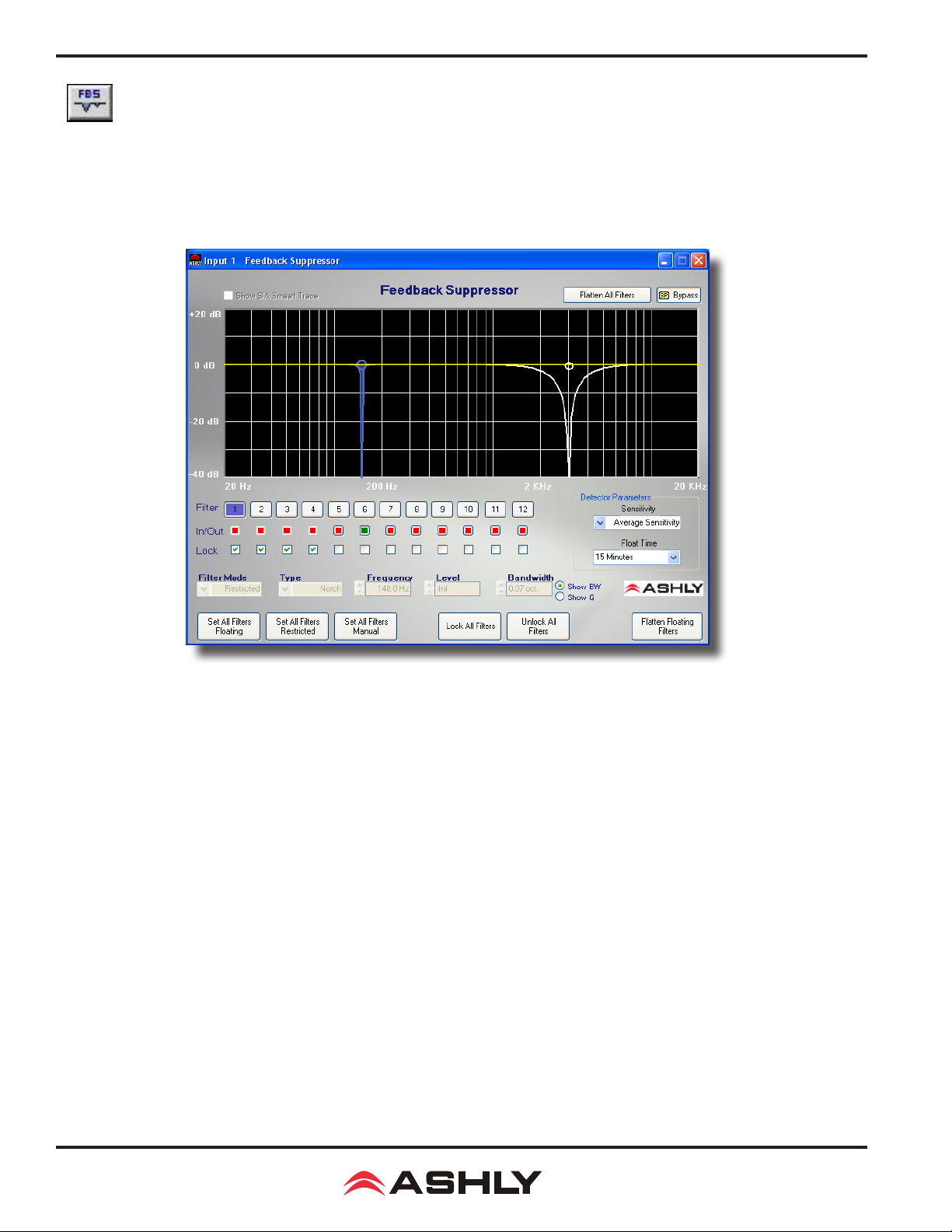
Operating Manual - nX, nXe, and nXp Power Ampliers
Feedback Suppressor (Inputs only)
The Feedback Suppressor (FBS) provides automatic feedback control. This is done by constantly monitoring the audio and
automatically adjusting any one of 12 lters to remove feedback. Notch and Parametric Filter types are used, depending on the
characteristics of the feedback. Because feedback suppression is more effective on an single input rather than an output mix of
channels, the FBS is only available on inputs, and only at the 48 kHz sampling rate. The FBS is DSP resource-intensive, so if a
FBS is used, the FIR lter on the same channel's output gets disabled in order to allow the DSP power necessary for the FBS.
Filter Parameters
Filter (number) - Current Active Filter (highlighted).
Filter In/Out - Green = Filter In (engaged), Red = Filter Out (disengaged).
Filter Lock - Locks Filter at its current setting, when locked the detector will no longer adjust the lter.
Filter Mode - There are three lter modes:
Restricted: Filter will only broaden or deepen.
Floating: Detector may release lter after oat time or modify lter type.
PEQ: Detector will not modify the lter however the user may control the lter.
Type - Selected Filter Type (Parametric or Notch).
Frequency - Selected Filter Center/Corner frequency.
Level - Selected Filter Boost/Cut amplitude.
Bandwidth - Selected Filter Bandwidth (or Q).
Feedback Detector Parameters
Sensitivity - Detector Sensitivity to feedback
Float Time - Time before a oating lter will start to release.
34
Page 35
Operating Manual - nX, nXe, and nXp Power Ampliers
Background Information
The feedback suppressor uses both notch lters and parametric lters to automatically and quickly suppress multiple feedback
tones and also produce a smooth equalized response which sounds pleasing for music and speech program. Before using the
FBS (Feedback Suppressor), it is helpful to understand the following basic concepts in order to effectively suppress feedback
and achieve good sounding audio program.
Each of the 12 FBS lters available on each FBS input channel can be selected between three different modes:
Restricted - The lter's attenuation level can only be made deeper, or lter bandwidth made broader by the FBS.
Floating lter - The lter's parameters are dynamic in that the FBS will slowly remove the lter if no longer needed and
redeploy at a different frequency as needed. Only oating lters are affected by the Float Time parameter which is the time after
which the FBS will slowly remove the lter.
Manual lter - The lter is not automatically controlled by the FBS, but can only be controlled by the user.
The FBS will automatically use available restricted lters rst. If there are no more restricted lters available, the FBS will
automatically use oating lters. The FBS will not automatically change manual lters.
The Sensitivity Control simply adjusts how sensitive the FBS algorithm is to detecting feedback and inserting lters. For example,
a setting of Very Sensitive means the algorithm will aggressively look for anything that could be feedback and hence it may
often insert lters on musical tones. A setting of Very Insensitive means that the FBS would only insert a lter in the presence
of a prolonged feedback tone with very little background noise. The optimal setting of the Sensitivity control depends on both
the spectral content of the audio program (how much the musical instruments sound like feedback), and also on the amount
of background music and noise which tends to mask feedback from the detector. It is best to start with an Average Sensitivity
setting and experiment.
A Locked lter means that the lter is prevented from being changed in any way, either automatically by the FBS or manually
by the user. To change or reset a lter, it must rst be unlocked.
FIR Filter (Outputs only)
The FIR (Finite Impulse Response) lter is typically used when a speaker manufacturer develops and provides a proprietary
FIR coefcient le that corresponds directly to their own loudspeaker or speaker cabinet, addressing frequency and phase issues
based on their own measurements and formulations. Plugging in a FIR lter block on a DSP output and then clicking on it will
prompt the user for a *.r or *.csv text le, which is then loaded and applied to the output DSP. The two le types will have
identical coefcient code, however the *.r le may add comments (designated by a semi-colon) or a key=value pair denition
such as sample rate. Either le type will work with Proteane Software.
Simple *.r le example:
; comments section
sampleRate = 48000
+0.0000042920
+0.0000030236
Simple *.csv le example:
+0.0000042920
+0.0000030236
-0.0000040482
-0.0000040482
Protea software does not offer the ability to view or edit the EQ curve produced by a FIR lter. Also, FIR lters are very DSP
intensive, so if a FIR lter is used on an output channel, that same numbered input channel's Feedback Suppressor will not be
available in order to allocate enough DSP power to the FIR lter. FIR lters can only be used on outputs, only at 48kHz sampling
rate, and can have from 2 up to 384 taps.
35
Page 36
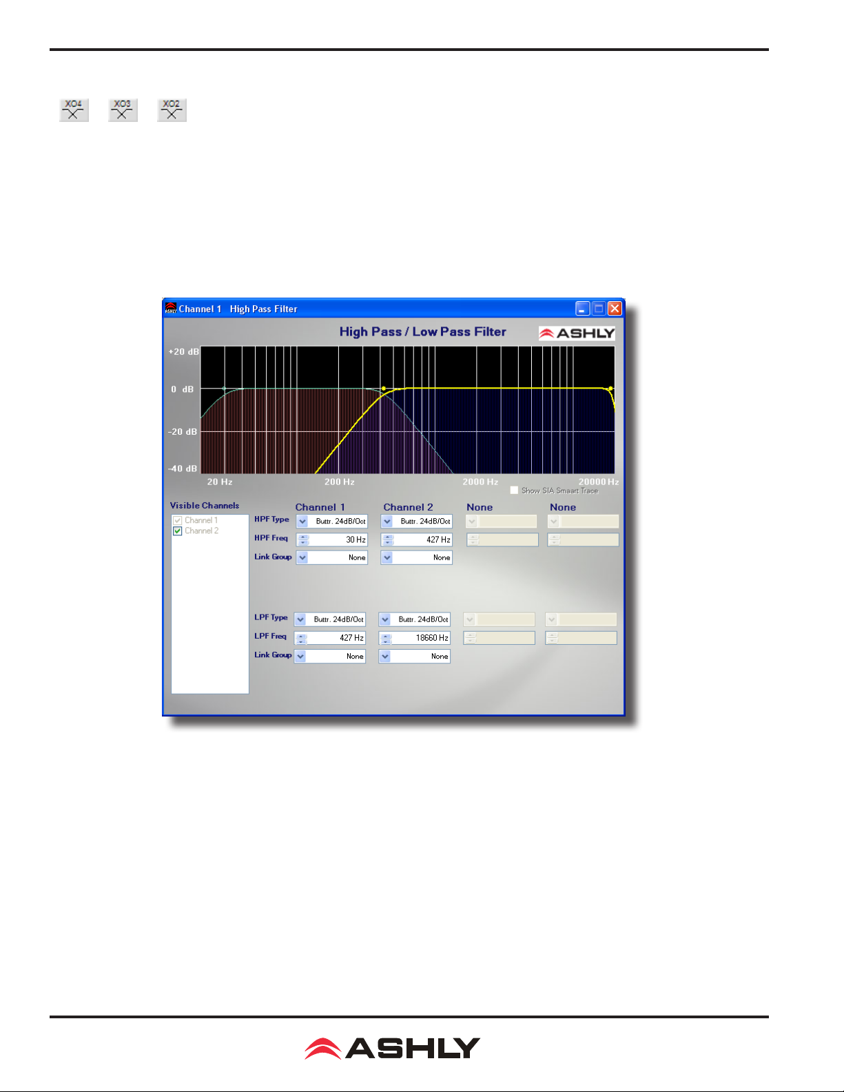
Operating Manual - nX, nXe, and nXp Power Ampliers
4) Crossover Functions
Four-Way, Three-Way, and Two-Way Crossover (outputs only)
The Crossover tool offers a convenient way to congure amplier outputs. Depending on whether the desired crossover is two,
three, or four-way, all High-Pass (HPF) and Low-Pass Filters (LPF) are automatically placed on output channels. Initial crossover
frequencies are assigned with the default lter type of 24dB/oct Butterworth, both of which can be changed. In the frequency
response display screen, all currently loaded lter frequencies are available for editing by Left-Click dragging a HPF/LPF node,
or by using the text boxes below the GUI.
Warning: High Pass Filter determines the lower frequency limit of the signal, while the Low Pass Filter determines the upper
frequency limit. Be careful not to accidentally send low frequency signals to high frequency drivers. Check the loudspeaker
specications to determine a safe operating frequency range.
Available Filter Types:
Bessel - 2nd, 3rd, 4th and 8th order (12, 18, 24, 48 dB/octave)
Butterworth -2nd, 3rd, 4th and 8th order (12, 18, 24, 48 dB/octave)
Linkwitz-Riley -2nd, 4th and 8th order (12, 24, 48 dB/octave)
The following paragraphs summarize the three primary lter types offered:
Butterworth
Butterworth lters individually are always -3dB at the displayed crossover frequency and have a "maximally at" passband and
sharpest transition to the stop-band. When a Butterworth HPF and LPF of the same corner frequency are summed, the combined
response is always +3dB. Note that when 12dB/octave Butterworth HPF and LPF lters are used to create a crossover, the
polarity of one of the outputs may need to be inverted to compensate for the phase shift of the lter.
36
Page 37
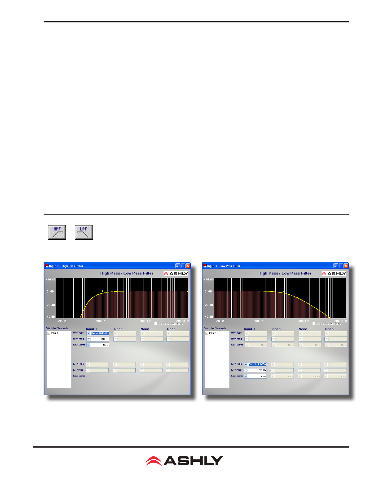
Operating Manual - nX, nXe, and nXp Power Ampliers
Bessel
These lters, as implemented in Ashly's NE devices, are always -3dB at the displayed crossover frequency. Bessel lters have
a maximally at group delay. Stated another way, Bessel lters have the most linear phase response. When a Bessel HPF and
LPF of the same corner frequency are summed, the combined response is +3dB for 12dB/oct, 18dB/oct, and 48dB/oct Bessel
lters, and -2dB for 24dB/oct Bessel lters. One of the outputs may need to be inverted when using either 12dB/oct or 18dB/
oct Bessel HPF and LPF's to create a crossover to compensate for the phase shift of the lter.
Linkwitz-Riley
The 12 dB/oct, 24dB/oct, an 48dB/oct Linkwitz-Riley lters individually are always -6dB at the displayed corner frequency,
however the 18dB/oct Linkwitz-Riley lters individually are always -3dB at the displayed corner frequency. The reason for this
is that Linkwitz-Riley lters are dened in terms the summing of two adjacent HPF and LPF lters when used in a crossover,
rather than dened in terms of the pole-zero characteristics of individual lters. The 18dB/oct Linkwitz-Riley individually are
18dB/oct Butterworth lters in that they have Butterworth pole-zero characteristics and also satisfy the criterion for LinkwitzRiley lters. When a Linkwitz-Riley HPF and LPF of the same corner frequency are summed, the combined response is always
at. With 12dB/oct Linkwitz-Riley crossover lters, one of the outputs must be inverted or else the combined response will
have a large notch at the crossover frequency.
Crossover Notes
When used in a crossover, lter type will affect the way adjacent pass-bands interact near the crossover point. When electrically
summed, 24dB/octave Linkwitz-Riley lters produce a at transition through the crossover region, assuming that the HPF and
LPF are set to the same corner frequency. This makes 24 dB/octave Linkwitz-Riley lters quite popular. However, crossover
lter types must be carefully selected to match the acoustic response of the specic loudspeaker system. Please consult the
manufacturer of the loudspeaker system for recommended crossover frequencies and lter types.
HPF and LPF lters
HPF and LPF are single ended lters similar to crossover lters, and are available on inputs and outputs.
37
Page 38
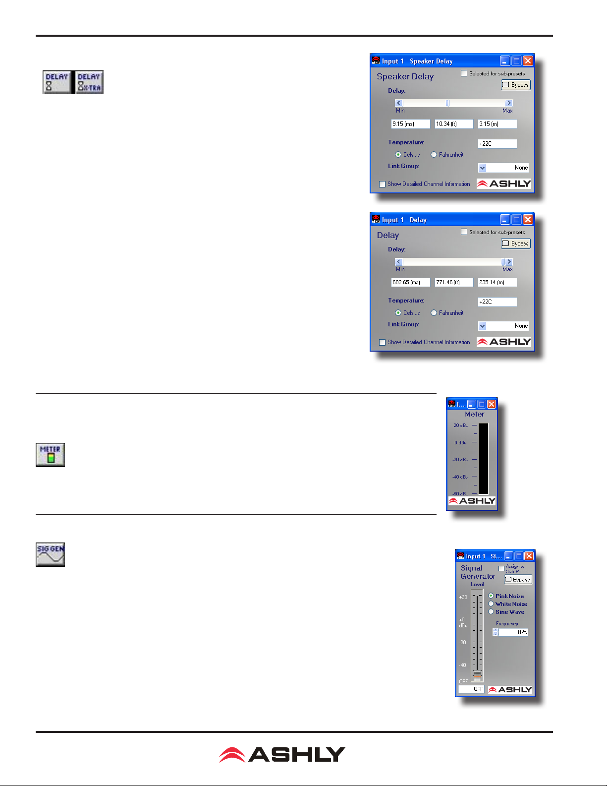
Operating Manual - nX, nXe, and nXp Power Ampliers
5) Delay
Speaker Delay and Delay
Both the Speaker Delay and Delay allow the signal to be delayed by a given number
of samples (a given amount of time). The only differences between the Speaker
Delay and Delay is the total amount of delay available and the amount of DSP
resources used by each block. The Speaker Delay uses far less DSP resources than
the Delay and should be used rst, whenever possible. Note that the total amount
of delay available from each block will vary with sampling rate. For convenience,
if both the standard and extra delay are used, parameters for both can be displayed
simultaneously on a single control screen.
For linking purposes, Speaker Delays are linked only to other Speaker Delays, and
Delays are linked only to other Delays. Typically the Speaker Delay is useful when
aligning speaker drivers or other locations where only a short delay is required. This
leaves processing available for other functions.
Parameters
Delay - Amount of delay added to the signal (presented in milliseconds, feet, or meters).
Temperature - Local temperature, used to calculate the speed of sound though air
and thus the distance orresponding to the delay time.
Link Group - The link group to which the delay's parameters will be linked.
Show Detailed Channel Information - If both Base and Extra Delay are used, this
allows all parameters to be viewed in a single window.
6) Metering
The Audio Meter does not affect the audio signal. It allows the signal to be monitored at any
location in the signal chain. Display range is -60dBu to +20dBu.
7) Signal Generator
The Signal Generator creates its own Pink Noise, White Noise or Sine Wave output, replacing any
audio signal in the chain before it. When bypassed, the Signal Generator allows the input signal to pass to the
output of the block unaffected. White Noise is randomly generated broadband noise, while Pink Noise is bandlimited to 20Hz - 20kHz to contain equal energy in any octave (-6 dB per octave low-pass ltered). The Sine
Wave has adjustable frequency. These signals may be generated at any level from -50dBu to +20dBu.
Parameters
Mode - The type of signal to be generated (Pink Noise, White Noise, Sine Wave)
Frequency - Frequency of signal to be generated (sine wave only).
Level - RMS level of signal generated.
Bypass - Turns off generated signal, and allows input to be passed through to output unaffected.
38
Page 39
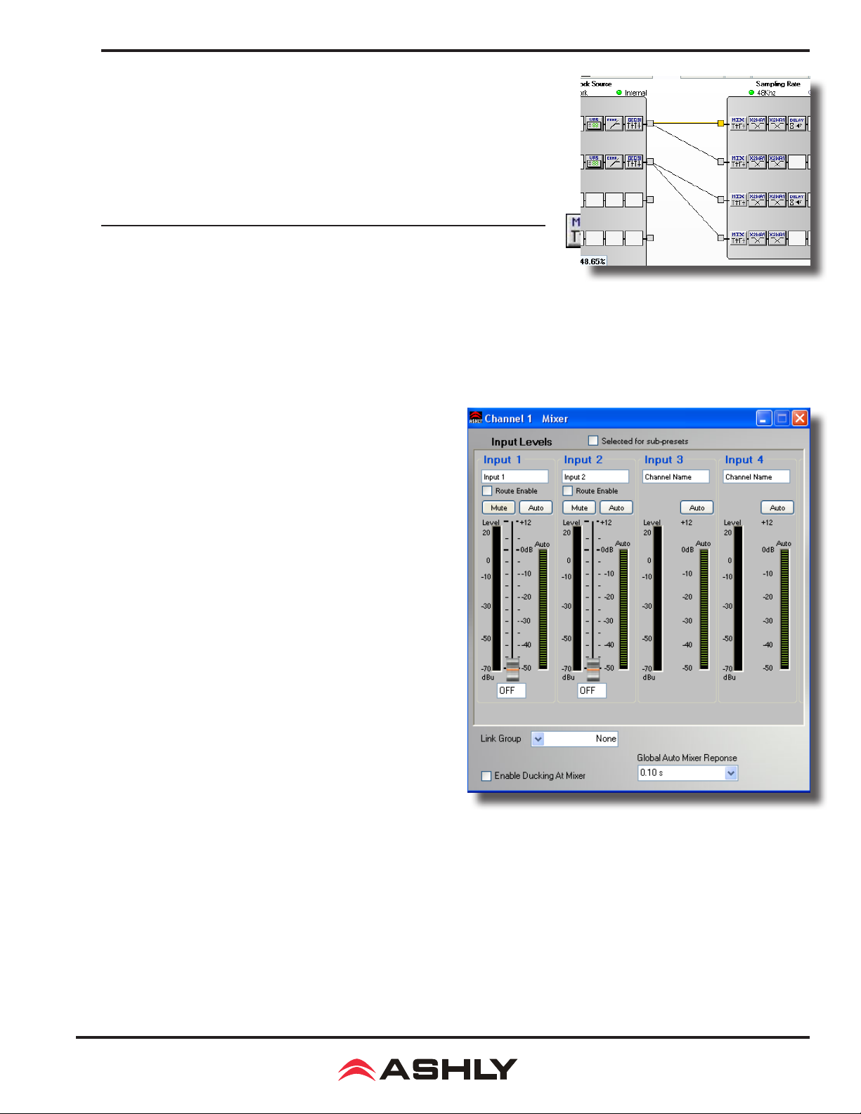
Operating Manual - nX, nXe, and nXp Power Ampliers
9.4d DSP Control Tab functions, continued . . . . .
Input/Output Matrix Router - Any input can be routed to any or all outputs.
Click and drag from the input to output to assign routing. For faster routing of a single
input or output to multiple channels, highlight its node and then press Ctrl+Click over
the desired nodes to connect to. To delete a route or clear the matrix, right click on
the routing line or node. Also, right click anywhere in the matrix area to bring up a
menu of common routing choices.
Matrix Mixer and Auto Mixer
Matrix Mixer
nX ampliers use the Matrix-Mixer to adjust the level of an input channel source to a routed output, typically at unity gain.
Inputs must be routed to an output channel using the Matrix Router (see previous section), then must be mixed using that output
channel's Matrix Mixer, either manually or with the Automixer. Practical use of the Auto-Mixer is minimal on nX ampliers
since there are only two or four input channels and no on-board mic preamps. Nevertheless, a description of all features follows:
Matrix Mixer/Auto Mixer Controls and Indicators
Input Name - An editable text label for the user to identify the
name of the input signal. This is the same text label as shown
on the inputs in the DSP Controls window.
Input/Output Matrix Router
Route Enable checkbox - Selected to make the mixer input
signal connection. Checking or unchecking this box has the
same affect as dragging or deleting the signal routing lines in
the DSP Controls window matrix mixer.
Mute Button - Mutes the input signal before the auto/manual
mixer. This does not light the front panel Mute LED.
Auto Button - Selects the mixer input channel as an automixer
channel when pressed in, versus a manual mixer channel when
pressed-out. Manual and automixer channels both get summed
into the output mix, however the manual channels operate
independently and do not participate in the automatic mixing
operation.
Fader Control - Adjusts the mixer input level for an automatic
or manual mixer channel before any automatic mixing takes
place.
Level Meter - Displays the input signal level prior to the
fader control or automixing attenuation. This meter is a peak-
responding signal level meter.
Duck Indicator - Displays when the input channel is being
ducked (attenuated) by the ducker function. This indicator is only visible when ducking is enabled at the mixer.
Auto Meter - Displays the automixer's attenuation applied to the signal before mixer summing.
Output Matrix Mixer
Channel Gain Value - Shows the total decibel gain applied to the input channel which is combined from the mixer fader control
and any remote level controls assigned to the matrix mixer. This gain value does not include the automixer gain value, and is
applied to the signal before the automixer.
Link Group - Allows multiple output mixers to be linked such that any control change made to one mixer will make an identi-
cal control change to any other mixer assigned to the same link group. The Route Enable control does not get linked however,
in order to maintain separate channel routing when controlling a stereo mix.
39
Page 40

Operating Manual - nX, nXe, and nXp Power Ampliers
Global Automixer Response - Controls the response time constant of all output automixers. The automixer response time is
the speed in which the automixer makes gain changes in response to the input signal RMS levels. This value is shared among
all automixers.
Enable Ducking At Mixer - Checkbox allows selecting the ducking action to be applied at the mixer's summing point rather
than in the signal path prior to the mixer. This allows some output mixer zones to have ducking action applied while other output
mixer zones do not have ducking applied.
Auto Mixer
The automixer is designed primarily to automate the mixing of multiple speech microphones to follow the dynamic nature of
the speech dialog and attenuate idle microphones. The automixer may also be used in conjunction with the Autoleveler, Compressor, or Gate on the input signal paths. This gives the user more advanced control of varied input signal levels produced by
different talkers. A Feedback Suppressor function may also be used on the inputs to further help control feedback problems.
Ashly Auto Mixer Technology
The automixer function is a "gain-sharing" type which automatically makes smooth gain transitions on all automixer input channels to achieve a constant total system gain. This gain-sharing method of automixing has been found to be superior to "gating"
automixers due to the following characteristics:
1) The automatic gain action has a smooth transparent sound as though a person were mixing the inputs to follow the audio
program rather than rapid gating on-and-off of channels.
2) Properly designed gain-sharing automixers correctly adjust for mixing of coherent versus non-coherent signals for a more
consistent nal mix level without feedback as channel gains are automatically changing.
3) A gain-sharing automixer is easier to setup and adjust without the need for threshold, attack, release, depth, and Number of
Open Mics (NOM) controls.
Mixer input channels can be individually selected as auto-mixed or manual mixed, all summed together to the same mixer
output. Channels which are selected as Auto will participate in the automix in that they will contribute to the automatic adjustment of other automix channel gains. Likewise, their channel gain will be affected by the signal level present on other automix
channels. Manual mixer channels (not selected as Auto) will mix independently of the automixer channels into the output, only
controlled by their fader setting. The fader on Auto channels still controls the input level before automatic mixing takes place
so that more of the system gain can be applied to one channel versus another.
Automixer Setup
Setting-up the Ashly gain-sharing automixer is quite simple compared to other gating-type automixers. The following procedure
is recommended for most multi-microphone speech applications.
1) Start with all mixer faders off and the Automixer Response Time set to 0.1 seconds.
2) Select the input channel routes as desired in the matrix mixer and select Auto on the channels to be automixed.
3) Start with one of the main speech channels, or one which is centrally located. Slowly increase the fader for this one channel
until feedback just starts, then lower the fader approximately 3 dB to stay comfortably below feedback. This sets the total mixer
system gain.
4) Now increase the other routed input channel faders to approximately the same position as the rst channel used in step 3.
The system will not feedback because the automixer will slowly attenuate the active channels as more channels are turned-on
to maintain a constant total system gain as set in step 3.
5) During the program, individual channel faders may be raised or lowered to adjust for the weakness or strength of the respective talkers while the automixer is active.
40
Page 41
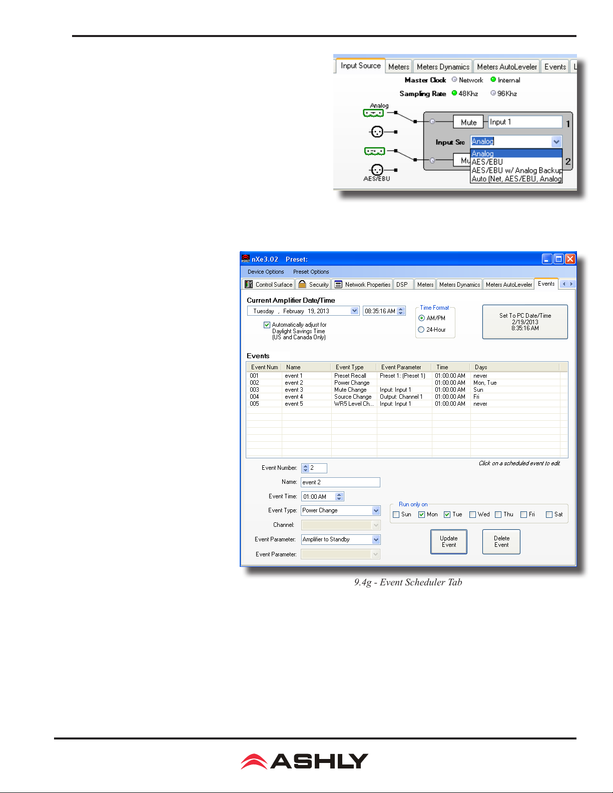
Operating Manual - nX, nXe, and nXp Power Ampliers
9.4e Input Source Tab
Inputs are analog balanced line, AES3 digital audio (optional), or
network audio (optional). Setting the input source to Auto gives
priority to network audio, then AES3, then analog.
9.4f Metering Tabs (not shown)
There are three meter tabs, including general I/O Meters, Meter
Dynamics for gate and compressor/limiter functions, and Auto-
leveler Meters. All meter tabs display both DSP input and DSP
output level for each channel.
9.4g Events Tab
The Events (Event Scheduler) tab allows
the user to program specic device ac-
tions to occur based on the time of day
or day of the week. Scheduled events
can include Preset Recall, Power Status
Change, Channel Mute, Output Source
Select, and certain remote control set-
tings. Up to 100 events can be scheduled.
All event schedule data is stored in the
amplier.
9.4e - Input Source Tab
A common use of the event scheduler
would be for programmable energy ef-
ciency. Schedule the amp to go idle or
off during down times, and turn back on
when the facility opens for business.
The date and time of the amplier's Real
Time Clock (RTC) can be manually set
by the user, or set to the host PC clock.
There is an internal battery that powers
the RTC that has an estimated life of 12
years. If this battery fails, the RTC will
not function until the battery is replaced
by a qualied service technician.
9.4g - Event Scheduler Tab
9.4h Fault Log Tab (not shown)
The Fault Log is a register of amplier
events triggered by fault conditions and date/time changes . It is useful for diagnosing an amplier/system problem by allowing
the administrator to review events which may have led to a fault condition. The log can be saved as a XML text le.
41
Page 42

Operating Manual - nX, nXe, and nXp Power Ampliers
10 REMOTE CONTROL FUNCTIONS
This section details nXe and nXp amplier remote control functions (see section 11 for remote control by Ashly device). Base
nX model amplierss have no remote control capability other than DC level control.
iPad control of select amplier functions: "Ashly Remote" can be downloaded from the iTunes App Store. “Ashly Remote”
is an application used to create a custom and secure graphical user interface (GUI) for Ashly networked devices via iPad wireless control. The sound system designer creates a GUI specically tailored for the end user and their networked Ashly products,
allowing them remote control access to select audio functions. Visit the Ashly website for details.
Function Control Device(s)
• Power On/Standby iPad, Contact Closure, Proteane Software, Event Scheduler
• Front Panel Controls Disable Proteane Software
• Sleep Mode and Clock Timer Proteane Software
• Remote Preset Recall iPad, Proteane Software, Contact Closure, WR-1.5, WR-2, WR-5,
neWR-5, Event Scheduler
• Remote Level Control iPad, WR-1, WR-1.5, WR-5, neWR-5,
RD-8C, FR-8/16, Event Scheduler, Proteane Software
• Remote Channel Mute iPad, WR-5, neWR-5, FR-8/16, Event Scheduler, Proteane Software
• Remote Zone Source Selection iPad, WR-5, neWR-5, Event Scheduler
10.1 On/Standby
nX ampliers have four possible power states; OFF, ON, STANDBY, and SLEEP.
1) Remote Control Standby - Using the Contact Closure -
connector pins labeled "STBY" and "G" can be wired to a switch and cause the amplier to go into standby mode when closed. Standby
mode draws <75W of mains power. For remote standby to work, the power switch must be turned on or turned on but disabled through
ne
Protea
software. To remove the amp from standby mode, open the STBY switch. Remote standby is unavailable on nX models.
2) Remote Control Standby - Using the Software Control Surface- nXe or nXp ampliers can also be put into standby
mode from software, functioning the same as the contact closure standby circuit on the back panel. Clicking on Standby in the
software control surface places the unit into standby mode until further action is taken to bring the amp out of standby. The
software standby control does not override the Remote Standby contact closure control, they both remain active at all times.
See Control Surface functions described in section 9.4a.
4) Remote Control Standby - Using the Event Scheduler -
functions including switching the amplier into standby mode. With the event scheduler, the installer can assign one or more times
of day or days of the week for the amplier to automatically go into and come out of standby mode, disabling overall function and
conserving power during those times when the amplier is not being used. See the Event Scheduler description in section 9.4g.
On nXe or nXp models only, the two back panel Euroblock
ne
Protea
software offers an event scheduler for several key
10.2 Front Panel Controls Disable
The power switch and attenuators on nXe and nXp ampliers can be disabled together from software. If the power switch has
been disabled while the amplier is on, the power switch LED remains lit and the front panel Disable LED is also lit, indicating
the power switch is inactive. If the AC mains power is removed while the power switch is disabled, the amplier still maintains
the <power switch disabled> status and will turn back on in the same state when AC power is restored. When the attenuators
are disabled, they revert to their full CW value.
*Note: Quickly pressing and releasing the recessed front panel factory reset switch when the amp is on will toggle the amplier
through the four possible sleep and front-panel-control-disable modes, as shown in section 4.3.
42
Page 43

Operating Manual - nX, nXe, and nXp Power Ampliers
10.4 Sleep Clock Timer
On all amplier models, the sleep clock timer can be enabled or disabled using the front panel factory reset switch as described in
section 4.3. On nXe and nXp series models only, the sleep clock timer can be adjusted from zero (off) to 120 minutes. If sleep mode
is enabled, and there is no audio activity for the duration of the sleep clock timer (xed at 30 minutes for nX series), the amplier
goes to sleep until signal is present again or until the power switch is pressed.
Note: The amplier can not be directly put to sleep or awakened from sleep using software or the event scheduler.
10.5 Preset Recall
Preset File: A preset le is created when the user saves all current software control settings for this amplier, essentially tak-
ing a snapshot of the entire amplier conguration. nXe and nXp ampliers can store up to 31 user-named presets. Individual
preset les stored on a PC use the extension (*.pne). A preset is saved to the amplier by using <Preset Options/Save Preset To
(device name)>, or saved to a PC using <Preset Options/Save To Disk>.
Sub Preset File: A sub preset le consists only of individually selected DSP parameters, and as such requires less load time
when it is recalled. Each DSP function has a check box that assigns it to a sub preset, then the sub preset is saved using <Preset
Options/Save Sub Preset to (device or disk)>. Sub preset lenames also use the *.pne extension, so for best results it's a good
idea to rename the le to indicate that it is a sub preset and not a full preset.
Presets and sub presets can be recalled to the nXe or nXp amplier using the following methods:
1) Protea
Recall (Sub) Preset from (device)>.
2) Contact Closure - There are four back panel contact closure pins labeled "Preset 1-4". When any one of those pins is con-
nected to the preset ground pin, the amplier loads the preset or sub preset 1-4 as stored in amplier memory.
3) WR-5 - A WR-5 appears in software as a captive device to its host amplier. The six buttons on the WR-5 can be programmed
to recall a specic preset or scroll through a dened list of presets.
4) neWR-5 - A neWR-5 will appear in the software menu tree as a device on the network, and must be assigned to the nXe or
nXp amplier under control. Like the WR-5, the six buttons on the neWR-5 can be programmed to recall a specic amplier
preset, or scroll through a dened list of presets.
5) Event Scheduler - Protea
With the event scheduler, the installer can assign one or more times of day or days of the week for the amplier to automati-
cally load a new preset.
Caution: A new preset may have dramatically different settings capable of damaging sound system components, so be careful
not to recall the wrong preset while the system is on.
ne
Software - Using Protea
ne
ne
software, click <Preset Options/Recall (Sub) Preset from Disk>, or <Preset Options/
software offers an event scheduler for several key amplier functions including preset recall.
10.6 Gain Control
1) WR-1 DC Level Control - The WR-1 remote DC level control potentiometer functions as if it were a front panel attenuator
but in a remote location. Attenuation from a remote DC level control attenuator is cumulative with all other attenuation for a
given channel, including the front panel level control.
1) WR-1.5 DC Level Control - The WR-1.5 offers a four position rotary switch for preset recall and a single DC level control
potentiometer. The gain control functions the same as in the WR-1.
2) WR-5 - The WR-5 buttons can be programmed to select single or multiple input or output channels for remote gain control
function. After programming one of the six buttons for gain control, then pressing that button, pressing the WR-5 up/down but-
tons will adjust the gain for all selected channels associated with that button. A gain range can also be set in software for each
gain button, with a top and bottom limit assigned per button. Note: To use this feature, a (ne)WR-5 Remote Gain tool must rst
be placed in one of the DSP processing blocks of the channels(s) to be controlled. Refer to section 9.4d.
43
Page 44

Operating Manual - nX, nXe, and nXp Power Ampliers
3) neWR-5 - The neWR-5 function buttons are assigned gain control function in the same manner as the WR-5, but instead of
connecting to the amplier's data port, the neWR-5 uses an Ethernet network connection.
4) RD-8C - The RD-8C is programmed from Protea
The RD-8C will appear in software as a captive device to the host amplier. Place a Remote Gain Control tool in the DSP section
(input or output) of Proteane software to allow the user to assign each RD-8C fader for control of a channel or group of channels.
The RD-8C also has a mute button for each fader which will mute all channels associated with that fader.
5) Event Scheduler - Protea
neWR-5 remote control gain. With the event scheduler, the installer can assign one or more times of day or days of the week
for the amplier to automatically change WR-5 and neWR-5 channel gain parameters.
6) Proteane Software - Real time gain control from software is available using a variety of tools. These include the main amplier's software control surface using the channel main fader, a single fader gain control placed on an input or output channel, a
digital VCA group gain control placed on an input or output, or a WR-5 (or neWR-5) gain control.
ne
software offers an event scheduler for several amplier functions including changes to WR-5 and
10.7 Channel Mute
1) WR-5/RD-8C - WR-5 buttons can be programmed to mute and unmute single or multiple inputs or outputs.
The RD-8C has a mute button associated with each fader which mutes those channels associated with that fader.
2) neWR-5 - The neWR-5 buttons can be programmed to mute and unmute single or multiple inputs or outputs.
ne
software when wired to a nXe or nXp amplier under software control.
3) Event Scheduler - The event scheduler can be set to automatically mute or unmute single or multiple inputs or outputs at a
predetermined day and time.
4) Protea
tion inputs and outputs, and the input source section.
ne
Software - The user can mute inputs or outputs in real time from within the software control surface, the DSP sec-
10.8 Zone Source Selection
1) WR-5 - A WR-5 is typically used to remotely control amplier functions within one specic zone. The amplier output(s)
used to drive loudspeakers in this zone are selected in the WR-5 Remote software device window under <Zone Setup / Select
Zone Outputs(s)>. The WR-5 buttons can then be programmed to select one or more input channels for that zone under WR-5
control. When multiple zone source select buttons are assigned uniquely different or overlapping inputs, each button will add to
or subtract from the other’s input selections, unless the Exclusive Source Selection box is checked in the zone setup, in which
case only the current button’s selected inputs will be used. The Disable Zone Level Control software checkbox allows input
source selections to be changed from the WR-5, but not the output gain. The output gain can still be adjusted from software, but
the WR-5 user is locked out from making zone output gain changes.
2) neWR-5 - The neWR-5 offers the same zone source selection capabilities as the WR-5, with the addition of programmable
limits on output gain level.
3) Event Scheduler - Use the event scheduler <Output Source Select> feature to enable or disable a single input source on a
specic amplier output or AUX output.
44
Page 45
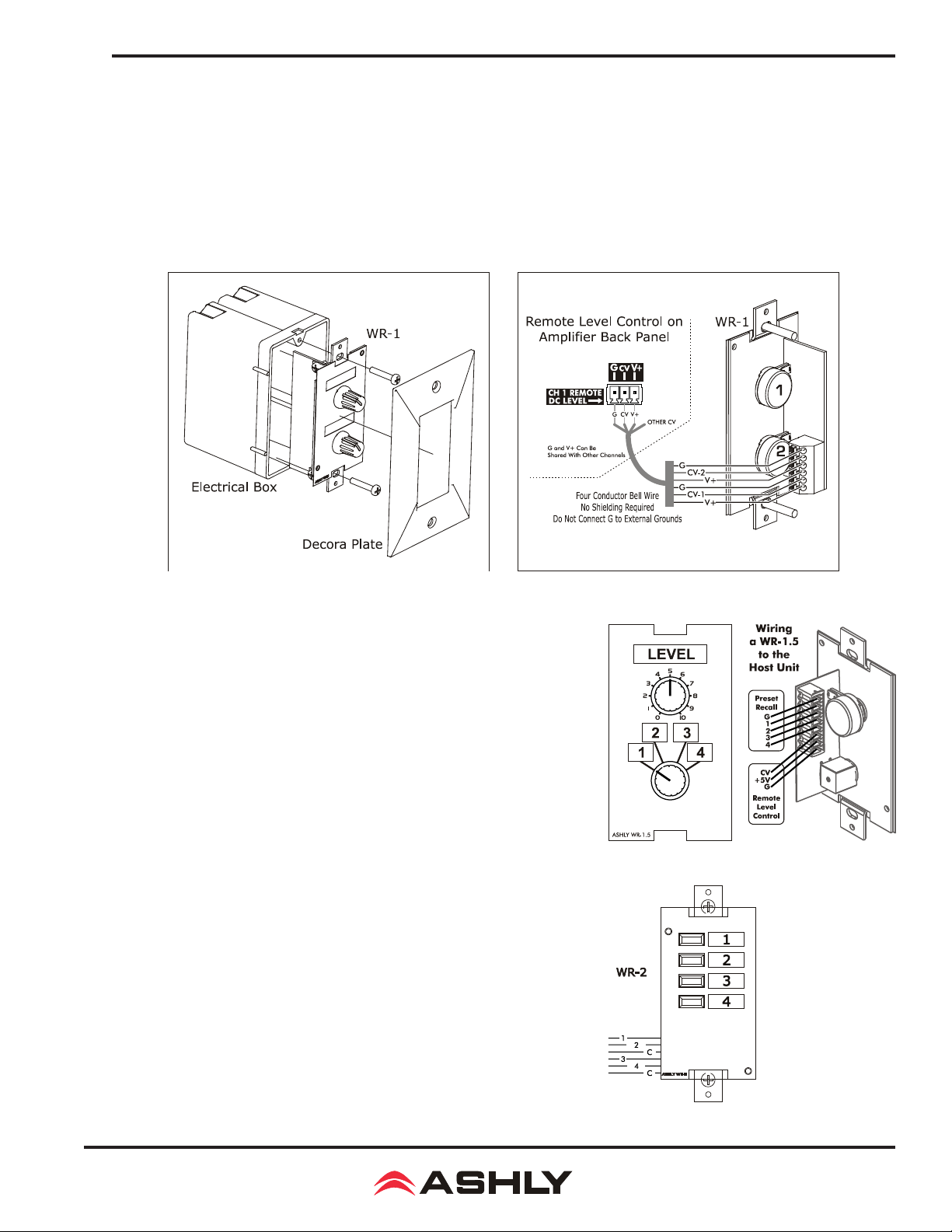
Operating Manual - nX, nXe, and nXp Power Ampliers
11 ASHLY REMOTE CONTROL DEVICES
In addition to iPad control, the following Ashly devices are available for remote control of amplier functions.
11.1 WR-1 Level Control (All nX models) - The WR-1 is a dual potentiometer remote volume control de-
signed to t in a standard wall electrical box, and is wired to the amplier back panel Euroblock connector labeled “CH
(1-4) Remote DC Level” using four conductor wire. If wiring a custom potentiometer other than the WR-1, connect
+5V from the remote level control Euroblock connector to the potentiometer's CW pin, GND to the CCW pin, and the
channel under control to the wiper. Do not connect the WR-1 remote level control ground to any other external grounds.
11.1 - WR-1 Assembly
11.2 WR-1.5 Level Control and Preset Recall Switch (Level
Control all models, preset recall on nXe and nXp models only) - The
WR-1.5 has a four position rotary switch for selection of stored amplier
presets 1-4, and a potentiometer for remote DC level control of one amplier
channel. Clear windows are provided for user generated labels.
11.3 WR-2 Preset Recall Switches (nXe and nXp only) - The WR-2
allows selection of stored amplier presets 1-4 using pushbutton switches.
Each pushbutton switch is connected to a preset recall pin on the back panel
of the amplier under control. The terminal numbers correspond to the rst
4 preset memory locations in the controlled amplier. Pressing a button
will select and load the corresponding amplier preset. Clear windows are
provided for a user-generated label.
11.1a - WR-1 Wiring
11.2 - WR-1.5
11.3 - WR-2
45
Page 46
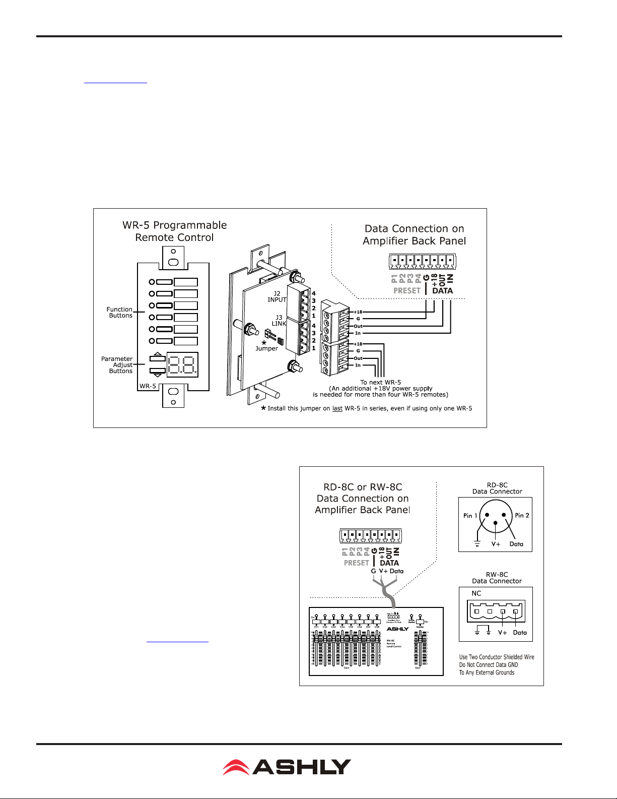
Operating Manual - nX, nXe, and nXp Power Ampliers
11.4 WR-5 Programmable Button Controller (nXp, limited nXe)
The WR-5 (owner's manual) is a programmable button remote control which mounts into a standard US electrical wall box and
is wired to the four back panel data port pins labeled "G, +18, Out, and In". Maximum wire length is 1000 ft using #24 gauge
twisted pair. A decora cover plate (not included) can be purchased at hardware stores to cover the electrical box and satisfy the
aesthetic needs of the installation. The WR-5 is phantom powered from the amplier. Up to four different WR-5 remotes can be
wired in series and phantom powered from one amplier, and more remotes can be added by using an Ashly RPS-18 remote power
supply or equivalent. To avoid potential static discharge disruptions to the WR-5 or it's data signal, be sure to connect the decora
plate and WR-5 frame directly to Earth Ground at the point of installation. Do not use the data ground wire as Earth Ground.
WR-5 buttons are programmed from Protea
in its WR-5 device window. Controlled functions include preset recall/scroll, mute, zone source selection, individual channel
and matrix point level control. Each button has a status LED. A clear window is provided for custom button labels.
ne
software after the WR-5 is wired to the amplier and assigned a unique ID number
11.4 - WR-5 Wiring
11.5 RD-8C Serial Data Fader Control (nXp only)
The RD-8C and RW-8C are eight channel remote slide fader
controllers which connect to the amplier's data port pins "G,
+18, Out, and In" for assignable remote level control of amplier input, matrix mixer, or output gain stages. Maximum cable
length is 1000 ft using #24 gauge twisted pair. The RD-8C is a
desktop controller, while the RW-8C mounts as a wall plate using
a standard North American 4-gang electrical box. Both units use
Euroblock connectors for wiring.. There are eight channels and
a master, each with a fader control and an on/off button. Note:
Only one RD-8C can be used per amplier, and use of an RD-8C
will exclude the use of the data port for a WR-5. One or the other
remote control device may be connected, but not both. For more
information, see the RD-8C owner's manual on the ashly website.
11.5 - RD-8C or RW-8C Wiring
46
Page 47
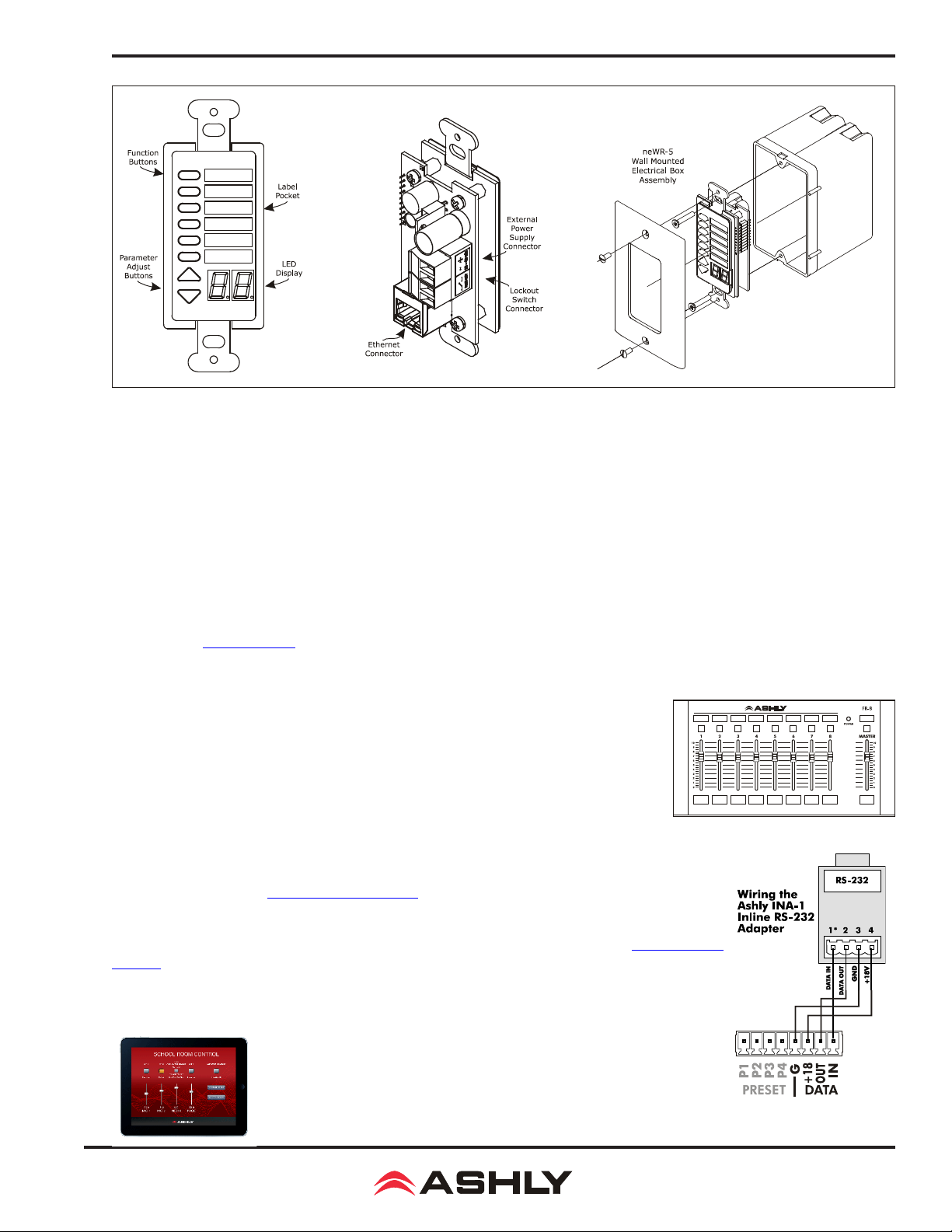
Operating Manual - nX, nXe, and nXp Power Ampliers
11.6 - neWR-5 Networked Programmable Remote Control
11.6 neWR-5 Programmable Button Controller (nXp, limited nXe)
The neWR-5 remote control is a networked version of the WR-5, using Ethernet instead of the data port to communicate with
the amplier. Connecting and powering the neWR-5 is done using Cat-5 Ethernet cable and an IEEE 802.3af Power over Eth-
ernet (PoE) switch, hub, or in-line PoE injector. If PoE is unavailable, the Ashly RPS-18 (sold separately) provides 15-48VDC
capable of at least 2 watts per neWR-5 and can be hard wired to the back of the neWR-5. PoE current draw is 38mA @48VDC
and 80mA@15VDC. A decora cover plate (not included) can be purchased at hardware stores to cover the neWR-5 electrical
box and satisfy the aesthetic needs of the installation. To avoid potential static discharge disruptions to the neWR-5 or it's data
signal, connect the decora plate and neWR-5 frame directly to Earth Ground at the point of installation.
The neWR-5 appears in the Proteane software device menu tree and must be assigned to the amplier under control. The neWR-5 has
six programmable function buttons which light up green, red, or amber to display status. Further information on LED status is found
in the neWR-5 owner's manual. To the right of the function buttons is a clear window for a printed function label to be inserted. The
two other buttons are used to adjust function parameters such as gain or preset number, and are indicated by the LED display.
There is also a hard-wired lock-out feature on the neWR-5, where the closing of a switch
wired to the lock-out Euroblock renders all buttons inactive.
11.7 FR-8 and FR-16 Networked Fader Controller (nXp only) The FR-8
and FR-16 are Ethernet based remote fader control units, with the ability to assign each
fader to control one or more input or output DSP gain stages (I/O mode), or control a DSP
matrix mixer input level (Mixer Mode). Each fader's button LED can alternately be as-
signed as an A/B source select for that fader. The button LED for each fader is normally
used to indicate assignable signal level/clip or mute status, but can alternately indicate
A/B source selection for that fader. The FR remotes can be wall mounted to electrical box,
panel mounted, or freestanding, and have a back panel contact closure for a control lockout switch.
See further details in the FR-8/16 owners manual, available on the Ashly website.
11.7- FR-8 (FR-16 Not Shown)
11.8 INA-1 Inline RS-232 Adapter The nXe or nXp amplier data port uses a proprietary
serial communications protocol which can be converted to RS-232 using the Ashly INA-1 RS-232
Adapter. This allows the use of third party RS-232 controllers. Note that the INA-1 uses a 5mm
Euroblock connector while the nX amplier uses 3.5mm Euroblock connectors, thus the cable con-
nection must be made accordingly. See the wiring diagram to the right.
11.9 Ashly Remote App for iPad® A custom and secure touch-screen
control surface for the iPad® can be designed using the <Ashly Remote> application, available free on iTunes® or via the Ashly website. Controls, labels,
and images are combined to manage key nXp amplier functions over a wireles
network connection.
11.8 - RS-232 Adapter
47
Page 48
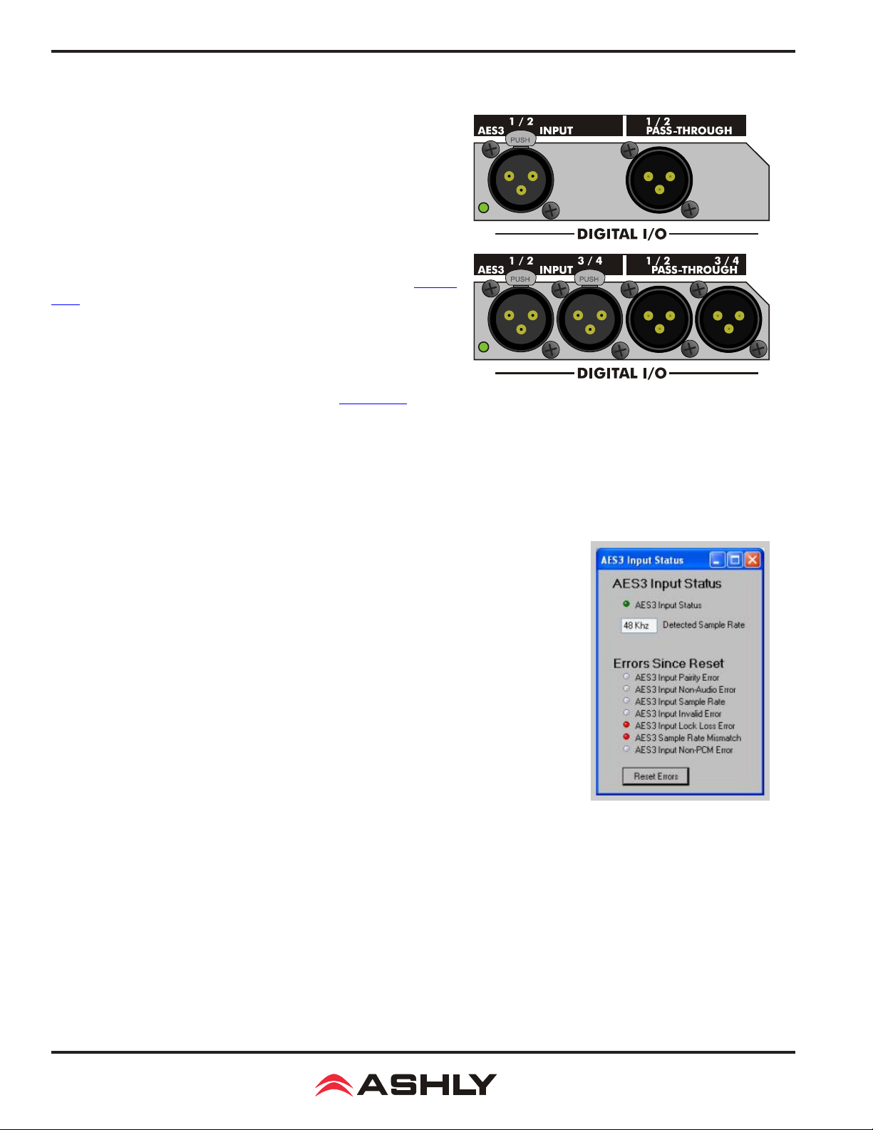
Operating Manual - nX, nXe, and nXp Power Ampliers
12 AES3 DIGITAL AUDIO INPUT/PASS-THROUGH
nXe and nXp ampliers support factory installed two or four channel
AES3 input options, named OPAES2* and OPAES4*. The AES3 format
uses two channels of digital audio transmitted over a single cable, maintaining a completely digital signal path into the amplier stage or into
the DSP stage if DSP is installed. Two channel ampliers accept a two
channel input with pass-through, while four channel ampliers accept
four input channels with pass-through. There is no AES3 output available from the amplier's DSP section, only pass-through of the input.
48kHz and 96kHz AES3 data rates are currently supported. The amplier's
internal sample rate must match the incoming AES3 sample rate (section
9.2h). A bicolor LED beside the AES3 connector indicates "Lock" (green)
or "Error" (red) as long as the AES3 receiver is active and is providing the
master clock source. The software AES3 control panel (shown below) shows
the status of the AES receiver in greater detail.
12.1 Source Selection The input must be congured via software to
accept the AES3 source before it can be used. See section 9.4e.
12.2 Cable Specication Standard 110 ohm microphone cable (3
conductor) with standard XLR connectors will support AES3 data transmission up to 100 meters.
OPAES2 and OPAES4 AES3 Options
12.3 Hardware Status Indicators
AES Status LED (green) - Receiver Rx1 is "Active", has locked onto an incoming AES/EBU signal, and data is ready for
processing. This LED is disabled when network audio provides the master clock.
AES Status LED (red) - Receiver Rx1 is "Active" but has an error. AES Signal will be muted.
See "Errors Since Reset" for specic error.
12.4 Software Status Indicators The AES/EBU status is found under the Device
Options>DSP Options menu:
AES3 Input Status (green): Receiver is "Active" and has locked onto an incoming AES/EBU
signal and data is ready for processing.
AES3 Input Status (red): Receiver is "Active" and has an error. See "Errors Since Reset"
for specic error.
Detected Sample Rate: Sample rate at which the AES/EBU receiver is locked.
Errors Since Reset: This displays AES3 data errors that have occurred during run time. Error
indications are latching, meaning they remain on even after the error condition has been cor-
rected, useful when diagnosing intermittent problems. Error indications are cleared by pressing
[Reset Errors] or by cycling power.
AES/EBU Parity Error: Parity error with incoming signal
AES/EBU Non-Audio Error: Incoming signal is not audio
AES/EBU Sample Rate: Unable to lock onto incoming frequency
AES/EBU Invalid Error: Incoming signal is invalid
AES/EBU Lock Loss Error: Unable to lock onto incoming signal, or lost lock of incoming signal
AES/EBU Sample Rate Mismatch: Receiver frequency does not match DSP frequency.
AES/EBU Non-PCM Error: Invalid AES format
AES3 Software Control Panel
*To use an OPAES2 or OPAES4 option in an nXe amplier (no DSP), the OPDAC4 must also be ordered and installed by the
factory. The OPDAC4 is not required on nXp models.
48
Page 49
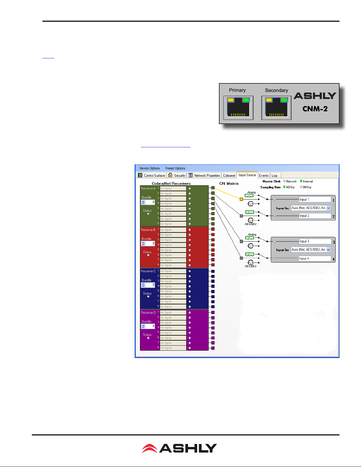
Operating Manual - nX, nXe, and nXp Power Ampliers
13 NETWORK AUDIO OPTIONS
Ashly offers a CobraNet and Dante network audio interface module that must be factory installed on nXe and nXp ampliers.
AVB will become available from Ashly in the future.
13.1 CobraNet®
CobraNet is an Ethernet-based digital audio transport technology de-
veloped and supported by Cirrus Logic. It is a combination of software,
hardware and network protocols which allows distribution of multiple
channels of real-time, high quality digital audio over a standard Ethernet
Network. Ashly nXe or nXp ampliers can be ordered with a factory in-
stalled CobraNet module. Proteane software will auto-detect if CobraNet
is installed. The amplier [Input Source] tab presents the Cobranet audio
routing and source controls as well as the status of individual receivers,
bundles, and channels. For more detailed information, please search
Proteane software on-line help, or visit the CobraNet home page.
Basic Terminology
Cobranet Receiver: There are four
receivers A, B, C, and D in ampliers
with CobraNet installed. Each receiver
can receive one Cobranet bundle
selected by the user. It is not necessary
to use all receivers. Depending on
how audio is sent from the CobraNet
transmitter, a single receiver can be
used and it's selected bundle and
channels routed to individual amplier
inputs using the Cobranet matrix in the
input source tab.
Cobranet Bundle: A Cobranet bundle
is a group of up to eight audio channels
which are transmitted together from
a single Cobranet device and may be
received by several Cobranet devices.
Each bundle is assigned a bundle
number. This number can be in the
following ranges:
0: Bundle is disabled.
1 to 255: These are multicast bundles
and are not recommended for most
situations.
256 to 65279: These are normal uni-
cast bundles and are most commonly
used.
65280 to 65535: These are "private" bundles and should not be used.
Cobranet Channel: Each bundle can contain up to 8 audio streams, or Cobranet channels. They are labeled 1 to 8. The Cobranet
channel number within the bundle that was assigned to the desired audio source is the same bundle and channel number that
should be selected when extracting and routing that original source to an amplier input channel.
49
Page 50
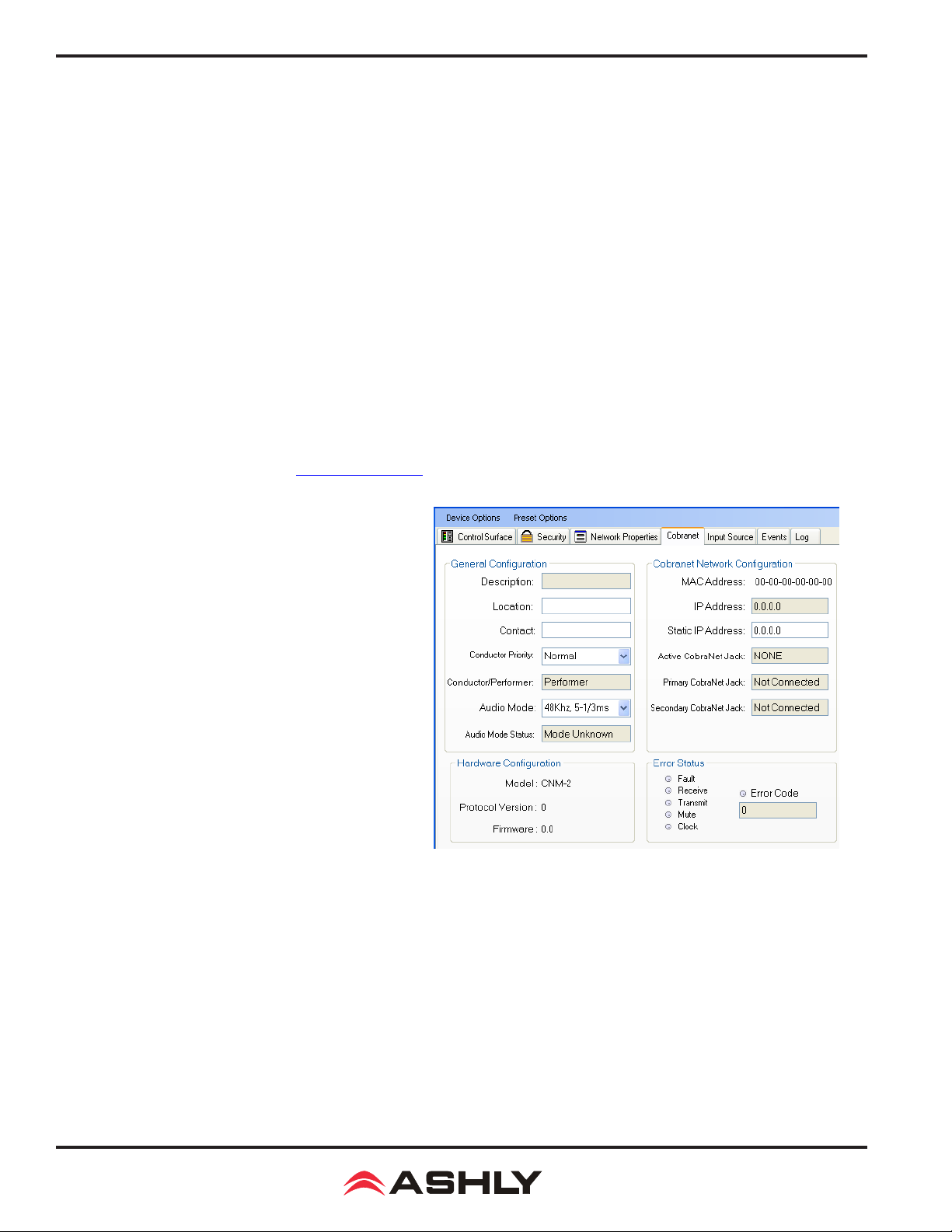
Operating Manual - nX, nXe, and nXp Power Ampliers
CobraNet Receiver Control
Bundle: Selected bundle this receiver is listening to.
Status: Indicates if a valid (green) bundle is being received.
Channel Status (1-8): The Signal Status indicates the current bit depth, sampling rate, and latency of the received audio stream.
The LED indicates this is a valid stream for this device. The sampling rate and latency of the transmitting device must match
that of the receiver.
CN Matrix: The Cobranet matrix allows the user to route any of the channels being received to the desired amplier inputs
channels.
Input Source Selection: The user can select the input source type for each amplier channel. For Cobranet, the selection must
be either [Network with Analog Backup] or [Auto]. When Analog Backup is engaged the device will switch to analog when
there is no valid CobraNet® data being received.
13.1a CobraNet Conguration Tab
A CobraNet Interface has several parameters that may need to be congured for proper operation. The "CobraNet Cong" screen
presents many of these networking controls as well as feedback as to the status of the CobraNet interface. It is also possible to
view and modify these parameters via CobraNet Discovery.
General Conguration
Description: Description of the Unit and its rmware.
Location: User-denable string typically indicating the
location of the CobraNet device.
Contact: User-denable string typically indicating the contact person for the CobraNet device.
Conductor Priority: The higher the priority the more likely
it is this unit will become the "Conductor". The Conductor
is the master clock and all other clocks are synchronized to
this clock.
Conductor/ Performer: Indicates if the unit is currently the
conductor or a performer. There can be only one conductor
on a CobraNet network.
Audio Mode: Sampling rate and latency for the device.
Both sending and receiving units must be congured for the
same Audio Mode.
Audio Mode Status: The current Audio Mode of the Unit. If a mode is not supported this status may not equal the selected mode.
Cobranet Network Conguration
MAC Address: The unique MAC address for the CobraNet interface. Note there is a separate MAC address
for the control-only interface. Both primary and secondary ports share the same MAC address.
IP Address: The current IP address for the CobraNet interface.
Static IP Address: When set to an addressable IP address (not 0.0.0.0) this is the IP address used by the CobraNet device on the
CobraNet ports. When this is 0.0.0.0, auto conguration is used by the CobraNet device to obtain an IP address. This IP address
can be provided by either BOOTP/DHCP or CobraNet Discovery (which uses RARP).
50
Page 51
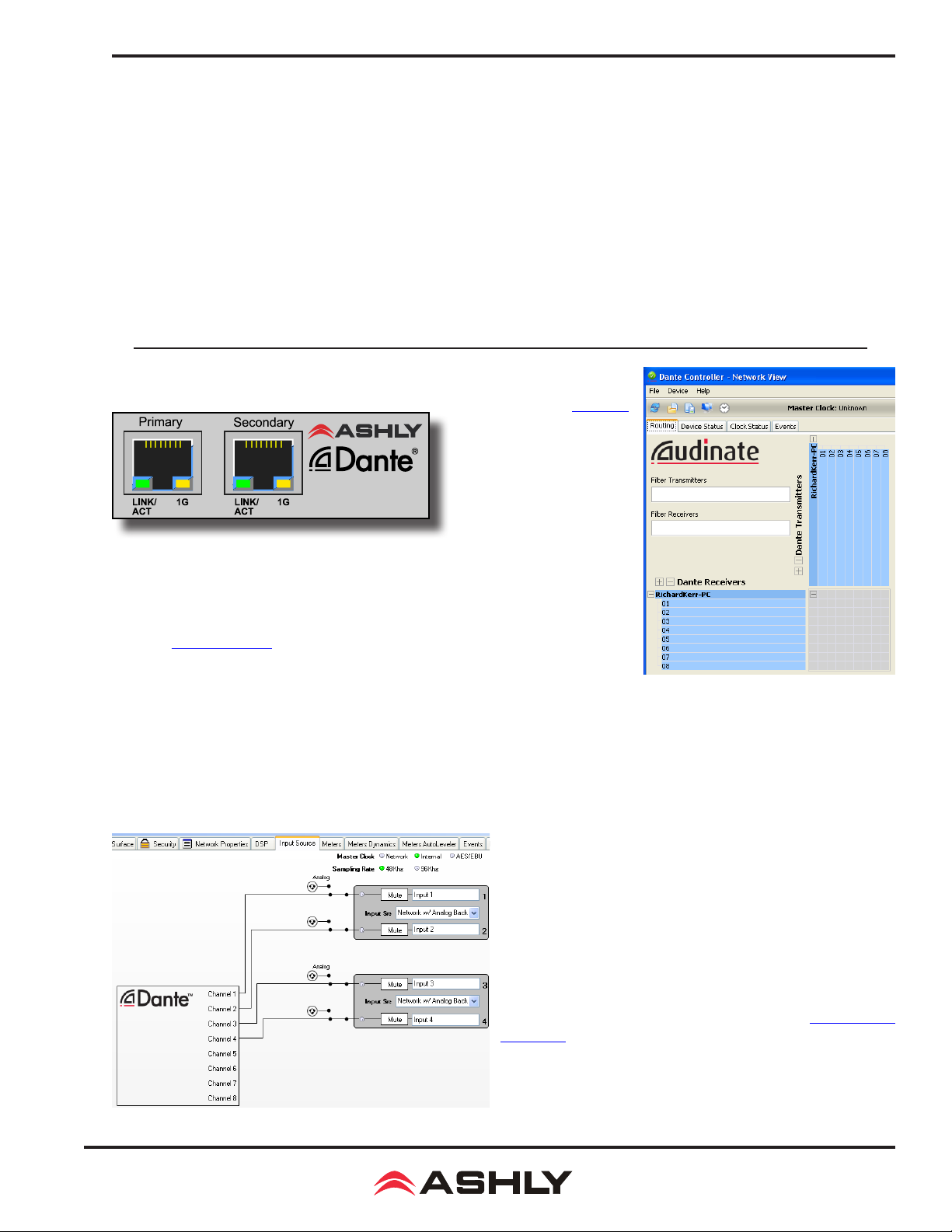
Operating Manual - nX, nXe, and nXp Power Ampliers
Active CobraNet Jack:
Primary CobraNet Jack: Shows the status of the primary CobraNet jack.
Secondary CobraNet Jack: Shows the status of the secondary CobraNet jack.
Shows which of the two CobraNet jacks is currently active (only one can be active at a time).
Error Indicators
Fault: A serious fault has occurred.
Receive: An error has occurred in the reception of a packet. Not necessarily a problem.
Transmit: An error has occurred in the transmission of a packet.
Mute: The interface is muting the outputs.
Clock: There is a problem with the Master Clock.
Error Code: Indicates a more detailed error code which can be looked up in the CobraNet Programmer's Manual.
13.2 Dante
be integrated into a Dante digital audio system by purchasing our OPTDante module
as a factory installed option, and controlled using Proteane software.
®
Network Audio
Dante, created by Audinate,
is an Ethernet based digital
AV network technology that
uses existing 100MB or 1GB
network infrastructure for
delivery of high performance,
high channel count audio
signals. Ashly products with
network audio capability can
Dante Controller (shown to right): Conguration of Dante audio streams requires
the use of Dante Controller. This free software from Audinate is available for Windows®
and Mac®. Dante Controller allows you to connect network audio receivers and
transmitters together using a simple matrix. The OPTDante option allows nXe or nXp
ampliers to receive Dante network audio. Additionally, nXp models can transmit
Dante signals from the amplier's post-DSP input channels.
Dante Receiver (shown below): Use Protea
for use with Dante. Go to the amplier's Input Source tab and select Network with Analog Backup as shown below. This connects
Dante transmitter channels that were assigned in Dante Controller to the amplier inputs. If the Dante transmitter source becomes
unavailable, the amplier input will automatically switch to it's analog input source.
ne
software to set up nXe or nXp inputs
Dante Controller
Transmitter/Receiver Matrix
Dante Transmitter (not shown): Newer nXp models (not nXe)
with Dante installed can now transmit Dante signal from each
input channel, post-input DSP. Visit the Ashly website Knowledge
Base to view a document listing the beginning serial numbers of
Dante-transmit capable nXp ampliers. Dante transmitter signals
are taken following each input channel's DSP section, but before
routing and the matrix mixer.
Dante transmitter status. Dante Controller automatically displays
all available nXp transmitter channels.
Proteane software does not show
Dante Virtual Soundcard (not shown): The Dante Virtual
Soundcard, purchased separately from Audinate, allows Windows
and Mac computers to act as a Dante audio source. Any sound
the computer can generate (background music, announcements,
VoIP sessions, etc.) can be routed to a Dante receiver via the
Dante Controller.
Dante Receiver Setup in Proteane Software
51
Page 52

Operating Manual - nX, nXe, and nXp Power Ampliers
14 nX AMPLIFIER TROUBLESHOOTING
No AC Power
1) Is the detachable AC power cord properly installed? Is it plugged into a known live outlet?
2) Has the power switch been disabled? (sec 4.7, 9.4a, 10.2)
3) Is the Power-On Delay time set high? (sec 3, 9.2c)
4) Is the amp asleep? (sec 4.6)
No Amplier Output
1) Is the amplier in Standby Mode? (sec 4.7, 6.3, 9.4a, 10.1)
2) Is there signal getting to the amplier?
3) Is the input signal properly wired (sec 2.2)?
4) Are output connectors properly wired (sec 2.3, 5.6)
5) Are front panel, remote control, or software attenuators turned down?
6) Is the amp channel muted from within the control surface, DSP section, remote control, output
mixer, or event scheduler?
7) Are dynamics or gain tool settings in the DSP section allowing signal to pass properly?
8) Is the signal properly routed to the desired output in the DSP Matrix Router? (sec 9.4d)
9) Is the fader level set properly in the DSP Matrix Mixer? (sec 9.4d)
10) If using a DSP crossover on the outputs, are the lter frequency settings correct?
11)
Did the event scheduler mute an output, change a preset or output channel source
12) Is the Amplier in Protect Mode? see below, or (sec 4.6)
? (sec 9.4g)
Protect LED is On (LED ERROR CODES)
1)
Does the amp still function, (fan still running)? If so, one or more channels of the amplier
is applying live countermeasures to compensate for overheating, power limiting, or a power supply
voltage fault condition. The amp will continue to operate in a reduced capacity until the fault condition is no longer present. Countermeasures include automatic attenuation of overheated or excessive output power, and treatments for DC power supply voltage irregularities.
2) Has the amp shut down (fan stopped) with protect, sleep, and power switch LEDs all
on? If so, a critical situation has triggered a fail-safe fault response, latching the amplier into its
shut-down state. AC power must be cycled to recover from this state. These conditions may be due
to internal component failure, so before cycling power, disconnect all speaker loads. The three critical fault conditions are:
A) Power Supply Fault mute LED is also on,
B) Output DC Fault mute LED and signal LED are also on,
C) High Temperature Fault clip/mute LED and temp LED are also on, there is a high temperature fault on the indicated channels
that could not be compensated for using countermeasures.
D) Microcontroller Thermal Fault - If protect, sleep, and power LED are on, and the temp and
clip LEDs are lit on all channels, there is a micro-controller thermal fault. This is not likely to occur unless the fan(s) fail and/or the amp is running in an unventilated environment.
3) Has the amp shut down (fans stopped) with Protect, Power Switch LED and Clip/Mute
LEDs all on? If so, this indicates that the power supply has shut down due to excessively high or
low AC Mains voltage. The amplier will automatically recover as soon as the AC voltage returns to
a safe operating level. (See sec 15 - Operating Voltage Range)
there is a power supply voltage fault condition on the muted channel(s).
If protect, sleep, and power LED are on, and one or more channel's clip/
If protect, sleep, and power LED are on, and one or more channel's clip/
there is a DC output fault on the indicated channel(s).
If protect, sleep, and power LED are on, and one or more channel's
If the protect, sleep, and power switch LED remain lit after cycling power, after the amplier is
allowed to cool, and after verifying that the AC mains are within an acceptable range, the critical
fault condition still remains and the amplier may require servicing.
52
Page 53

Operating Manual - nX, nXe, and nXp Power Ampliers
Clip/Mute LED Stays On
1) Is the front panel level control, Remote DC Level, or software control surface fader fully off?
2) Is the amplier muted from software, a remote control devices, or an event scheduler action?
Attenuators Don't Work
1) Are the front panel or remote attenuators disabled? (sec 4.4, 9.4a)
Amplier Not Recognized in Proteane Software
1) Is the PC successfully communicating with the network? (sec 8)
2) Is the amplier successfully communicating with the network? (sec 8)
3) Does the amplier name appear as green text in the Ashly Network device tree? (sec 9.1a)
4) Is the amplier device icon placed on the software project canvas a virtual device instead of a
live amp? Any virtual device MAC address will always read FF-FF-FF-FF-FF-FF. (sec 9.1b)
5) Was the amplier IP address auto-detected (recommended) or manually assigned? (sec 8.1)
6) Is rewall software blocking initial communication from the device? (sec 8.2)
Unable to Access Software Functions
1) Is the desired level of access granted to the current user in the security tab? (sec 9.4b)
Unable to Load Enough DSP Tools
1) Is the sample rate set to 96kHz? (sec 9.2h)
2) Graphic Equalizers have a much greater DSP "cost" than Parametric Filters. The Feedback
Suppressor uses even more DSP than the Graphic EQ. Use only as much EQ as is needed.
3) Speaker Delay uses less resources than Delay
Can't Use Any DSP Tools On Input or Output Channels
1) Has Input, Mixer, or Output channel DSP been disabled under Device Options? (sec 9.2j)
Event Scheduler Action Does Not Work
1) Does the amplier's date/time match that of the PC running software? (sec 9.4g)
2) Did you click the [Update Event] button after editing events?
Remote Control Troubleshooting
WR-5 or RD-8C Doesn't Work Properly
1) Is the remote wired correctly to the amplier Data connector?
2) If the WR-5 is the last one in series, even if it is the only one used, is the two pin jumper
properly placed on the circuit board header as shown?
3) Is the remote assigned its own unique device ID from within its device window?
4) If using WR-5 for gain control, is there a (ne)WR-5 Remote Gain function in a DSP
gain block on the channel to be controlled?
5)
The remote and it's data signal can be negatively affected by static discharge when touched. Refer
to the remote owner's manual for proper earth grounding.
neWR-5 or FR-8/16 Doesn't Work Properly
1) Is the remote successfully communicating with the network?
2) Is the remote connected to a switch, hub, router, or power injector providing sufcient Power
Over Ethernet (PoE), or using an external power supply?
3) Is the remote assigned within its device window to control the desired amplier?
4) Is the hardware lockout switch being used, disabling all buttons?
5) If using neWR-5 for gain control, be sure to install a (ne)WR-5 Remote Gain function in a DSP
gain block on the channel to be controlled.
6)
The remote and it's data signal can be negatively affected by static discharge when touched. Refer
to the remote owner's manual for proper earth grounding.
53
Page 54

Operating Manual - nX, nXe, and nXp Power Ampliers
15 nX AMPLIFIER SPECIFICATIONS
General Power Amplier Specications (0dBu = 0.775V rms)
nX Amplier Model nX3.04 nX3.02 nX1.54 nX1.52 nX8004 nX8002 nX4004 nX4002
Maximum Output Power
CEA-2006/490A, 20ms 1kHz 1%THD+N, 480ms 1kHz -20dB, 120VAC, all channels driven at rated load
Low Z output, per channel
2 Ohm . . . . . . . . . . . . . . . . . . . . . . . . . . . . . . .3000W 3000W 1500W 1500W 800W 800W 400W 400W
4 Ohm . . . . . . . . . . . . . . . . . . . . . . . . . . . . . . .2000W 2000W 1500W 1500W 800W 800W 400W 400W
8 Ohm . . . . . . . . . . . . . . . . . . . . . . . . . . . . . . .1250W 1250W 1250W 1250W 800W 800W 400W 400W
Low Z output, per bridged channel pair*
4 Ohm . . . . . . . . . . . . . . . . . . . . . . . . . . . . . . .6000W* 6000W* 3000W* 3000W* 1600W* 1600W* 800W 800W
8 Ohm . . . . . . . . . . . . . . . . . . . . . . . . . . . . . . .4000W* 4000W* 3000W* 3000W* 1600W* 1600W* 800W 800W
70V, 100V output, per channel
70V . . . . . . . . . . . . . . . . . . . . . . . . . . . . . . . . .2450W 2450W 1500W 1500W 800W 800W 400W 400W
100V . . . . . . . . . . . . . . . . . . . . . . . . . . . . . . . .1250W 1250W 1250W 1250W 800W 800W 400W 400W
70V, 100V output, per bridged channel pair*
140V . . . . . . . . . . . . . . . . . . . . . . . . . . . . . . . .4900W* 4900W* 3000W* 3000W* 1600W* 1600W* 800W* 800W*
200V . . . . . . . . . . . . . . . . . . . . . . . . . . . . . . . .2500W* 2500W* 2500W* 2500W* 1600W* 1600W* 800W* 800W*
*May require Class 3 speaker wiring, all others use Class 2 wiring. See section 2.3
Total AC Mains Power Draw - Typical input, all channels driven, 120VAC
Sleep. . . . . . . . . . . . . . . . . . . . . . . . . . . . . . . . .<1W <1W <1W <1W <1W <1W <1W <1W
Standby . . . . . . . . . . . . . . . . . . . . . . . . . . . . . .70W 40W 70W 40W 40W 25W 40W 25W
Idle (no signal) . . . . . . . . . . . . . . . . . . . . . . . . .100W 55W 100W 55W 70W 40W 70W 40W
1/8 max power, 70V. . . . . . . . . . . . . . . . . . . . .1880W 940W 1250W 625W 685W 345 375 190
1/8 max power, 100V. . . . . . . . . . . . . . . . . . . .1040W 520W 1040W 520W 685W 345 375 190
1/8 max power, 8 Ohm. . . . . . . . . . . . . . . . . . .1040W 520W 1040W 520W 685W 345 375 190
1/8 max power, 4 Ohm. . . . . . . . . . . . . . . . . . .1540W 770W 1250W 625W 685W 345 375 190
1/8 max power, 2 Ohm. . . . . . . . . . . . . . . . . . .2300W 1150W 1250W 625W 685W 345 375 190
AC Mains Current Draw - Typical input, all channels driven, 120VAC (divide in half for 240V)
Sleep mode. . . . . . . . . . . . . . . . . . . . . . . . . . . .100mA 100mA 100mA 100mA 100mA 100mA 100mA 100mA
Standby mode. . . . . . . . . . . . . . . . . . . . . . . . . .1.30A 0.70A 1.30A 0.70A 0.70A 0.38A 0.70A 0.38A
Idle (no signal) . . . . . . . . . . . . . . . . . . . . . . . . .1.85A 1.00A 1.85A 1.00A 1.30A 0.70A 1.30A 0.70A
1/8 max power, 70V. . . . . . . . . . . . . . . . . . . . .24.1A 12.1A 16.0A 8.0A 8.8A 4.6A 5.0A 2.6A
1/8 max power, 100V. . . . . . . . . . . . . . . . . . . .13.4A 6.7A 13.4A 6.7A 8.8A 4.6A 5.0A 2.6A
1/8 max power, 8 Ohm. . . . . . . . . . . . . . . . . . .13.4A 6.7A 13.4A 6.7A 8.8A 4.6A 5.0A 2.6A
1/8 max power, 4 Ohm. . . . . . . . . . . . . . . . . . .19.7A 9.9A 16.0A 8.0A 8.8A 4.6A 5.0A 2.6A
1/8 max power, 2 Ohm. . . . . . . . . . . . . . . . . . .29.5A 14.7A 16.0A 8.0A 8.8A 4.6A 5.0A 2.6A
Thermal Dissipation in BTU/hour with typical input, all channels driven, 120VAC
Sleep mode. . . . . . . . . . . . . . . . . . . . . . . . . . . . 3.4 3.4 3.4 3.4 3.4 3.4 3.4 3.4
Standby mode . . . . . . . . . . . . . . . . . . . . . . . . .238 136 238 136 136 85 136 85
Idle (no signal) . . . . . . . . . . . . . . . . . . . . . . . . . 340 187 340 187 238 136 238 136
1/8 max power, 70V. . . . . . . . . . . . . . . . . . . . . 2220 1110 1700 850 970 495 595 305
1/8 max power, 100V. . . . . . . . . . . . . . . . . . . . 1420 710 1420 710 970 495 595 305
1/8 max power, 8 Ohm. . . . . . . . . . . . . . . . . . .1420 710 1420 710 970 495 595 305
1/8 max power, 4 Ohm. . . . . . . . . . . . . . . . . . .1810 905 1700 850 970 495 595 305
1/8 max power, 2 Ohm. . . . . . . . . . . . . . . . . . .2720 1360 1700 850 970 495 595 305
Input Sensitivity - in Volts and dBu, per back panel DIP Switch gain and Output Mode settings, per model, 0dBu = 0.775V rms
Low Z (3.0x) Low Z (1.5x) Low Z (800x) Low Z (400x) 70V (all) 100V (all)
@26dB gain. . . 3.9V (+14dBu) 2.7V (+11dBu) 2.0V(+8.2dBu) 1.4V(+5.1dBu) 3.5V (+13dBu) 5.0V (+16dBu)
@32dB gain. . . 1.9V (+7.8dBu) 1.4V (+5.1dBu) 1.0V(+2.2dBu) 0.71V(-0.8dBu) 1.8V (+7.3dBu) 2.5V (+10dBu)
@38dB gain. . . 0.97V (+2dBu) 0.68V (-1.1dBu) 0.5V(-3.8dBu) 0.35V(-6.9dBu) 0.88V (+1.1dBu) 1.3V (+4.5dBu)
@1.4V gain . . . 1.4V (+5.1dBu) 1.4V (+5.1dBu) 1.4V (+5.1dBu) 1.4V (+5.1dBu) 1.4V (+5.1dBu) 1.4V (+5.1dBu)
54
Page 55

Operating Manual - nX, nXe, and nXp Power Ampliers
Distortion (SMPTE, typical) . . . . . . . . . . . . . . . . . . . . . . . . . . . . .<0.5%
Distortion (THD-N, typical)
(8 Ohm, 10dB below rated power, 20Hz-20kHz) . . . . . . . . . . . . <0.5%
Signal to Noise (26dB input sensitivity, 20Hz-20kHz, unweighted) . . .>114dB (3.0x models), >111dB (1.5x models)
>108dB (800x models), >105dB (400x models)
Frequency Response . . . . . . . . . . . . . . . . . . . . . . . . . . . . . . . . . . .20Hz-20kHz, +/-0.05dB
Channel Separation (dB from full output, 1kHz). . . . . . . . . . . . . .-75dB
Damping Factor (8 Ohm load, <1kHz) . . . . . . . . . . . . . . . . . . . . .>250
Balanced Input Connector (per channel) . . . . . . . . . . . . . . . . . . . .Euroblock (3.5mm), 1/4" TRS and XLR Combo jack
Input Impedance. . . . . . . . . . . . . . . . . . . . . . . . . . . . . . . . . . . . . .10k Ohm
Maximum Input Level . . . . . . . . . . . . . . . . . . . . . . . . . . . . . . . . .+21dBu
Bridge Mode Switch (per channel pair). . . . . . . . . . . . . . . . . . . . . In for bridged mode, Out for stereo
Remote DC Level Control (G, CV, V+ per channel). . . . . . . . . . . Euroblock (3.5mm), V+ is fully on, G is fully attenuated
DIP Switch settings (per channel)
Switches 1-2: Output Mode . . . . . . . . . . . . . . . . . . . . . . . . . . . . .Low Z, 70V, 100V output
Switches 3-4: Input Gain . . . . . . . . . . . . . . . . . . . . . . . . . . . . . . .26dB, 32dB, 38dB, 1.4V
Switch 5: Output Clip Limiter . . . . . . . . . . . . . . . . . . . . . . . . . . .On, Off
Switch 6: Input High Pass Filter . . . . . . . . . . . . . . . . . . . . . . . . . 80Hz 2nd order HPF - On, Off
Speaker Output Connector (per channel). . . . . . . . . . . . . . . . . . . . Neutrik SpeakON® NL4MD-H-2
nXe and nXp Models Only:
Control Network . . . . . . . . . . . . . . . . . . . . . . . . . . . . . . . . . . . . . .100MB Ethernet, RJ-45 connector
Remote Standby Contact Closure . . . . . . . . . . . . . . . . . . . . . . . . . Euroblock (3.5mm) - close contact pin to G for standby mode
Fault Logic Output (per channel). . . . . . . . . . . . . . . . . . . . . . . . . .
Fault Conditions . . . . . . . . . . . . . . . . . . . . . . . . . . . . . . . . . . . . .
voltage out of range, DC on output, microprocessor malfunction
(+5V and G pins available for logic sink and source)
Maximum Fault Pin Source Current. . . . . . . . . . . . . . . . . . . . . . 20mA
Maximum Fault Pin Sink Current. . . . . . . . . . . . . . . . . . . . . . . . 200mA
Preset Recall Contact Closure . . . . . . . . . . . . . . . . . . . . . . . . . . . . Euroblock (3.5mm) - close contact to GND for preset 1-4 recall
Data Connection. . . . . . . . . . . . . . . . . . . . . . . . . . . . . . . . . . . . . . .Euroblock (3.5mm) - Gnd, +18V, Data Out, Data In
AUX Output Connector . . . . . . . . . . . . . . . . . . . . . . . . . . . . . . . . . Balanced Euroblock (3.5mm)
AUX Output on two channel models. . . . . . . . . . . . . . . . . . . . . .
AUX Outputs on four channel models. . . . . . . . . . . . . . . . . . . . .
AUX Output Maximum Level. . . . . . . . . . . . . . . . . . . . . . . . . . . +21dBu
Network Audio Options (factory installed only) . . . . . . . . . . . . . .Dante (receive nXe & nXp, transmit nXp only), CobraNet
Digital I/O Option . . . . . . . . . . . . . . . . . . . . . . . . . . . . . . . . . . . . . AES3, two or four channel with zero-latency pass-through
Front Panel Indicators
Power Switch LED (white) . . . . . . . . . . . . . . . . . . . . . . . . . . . . .On, Off, Standby (ashing)
Clip/Mute LED (red) . . . . . . . . . . . . . . . . . . . . . . . . . . . . . . . . . .Per Channel - Clip @ 1dB below full output, Mute
Signal LED (green) . . . . . . . . . . . . . . . . . . . . . . . . . . . . . . . . . . . Per Channel - -18dB below rated output
Current LED (green) . . . . . . . . . . . . . . . . . . . . . . . . . . . . . . . . . . Per Channel - Brightness is proportional to output current
Temp LED (yellow) . . . . . . . . . . . . . . . . . . . . . . . . . . . . . . . . . . .Per Channel -
On full bright at 100% maximum operating temp, + protect
Bridge LED (green) . . . . . . . . . . . . . . . . . . . . . . . . . . . . . . . . . . .Per Channel Pair - On, Off
Protect LED (red). . . . . . . . . . . . . . . . . . . . . . . . . . . . . . . . . . . . . On for fault condition countermeasures or shut-down, Off
(See Troubleshooting section for Protect LED error codes)
Sleep LED (blue) . . . . . . . . . . . . . . . . . . . . . . . . . . . . . . . . . . . . .On when amp is asleep, on briey when sleep mode is enabled
Disable LED (yellow) . . . . . . . . . . . . . . . . . . . . . . . . . . . . . . . . . On when front panel controls are disabled, Off
Com LED (green) . . . . . . . . . . . . . . . . . . . . . . . . . . . . . . . . . . . .On for Ethernet activity or displaying Device ID
Attenuators. . . . . . . . . . . . . . . . . . . . . . . . . . . . . . . . . . . . . . . . . . .Per channel: front panel, software,
offset link group, and remote control. Fully off = Mute
Euroblock (3.5mm) - fault indicated by loss of 1Hz, 5V pulse signal
AC mains voltage, excessive internal temperature, power supply
AUX A & B use amp ch 1-2 signal, or use matrix mixer if DSP installed
AUX A, B, C, D use amp ch 1-4 signal, post DSP if installed
On dim at 90% of maximum operating temperature
Amplier Protection. . . . . . . . . . . . . . . . . . . . . . . . . . . . . . . . . . . .In-rush current, over-temperature, output DC,
output over-power, AC mains voltage, mains fuses
55
Page 56

Operating Manual - nX, nXe, and nXp Power Ampliers
Cooling. . . . . . . . . . . . . . . . . . . . . . . . . . . . . . . . . . . . . . . . . . . . . .
Power Cable Connector . . . . . . . . . . . . . . . . . . . . . . . . . . . . . . . .20A powerCON® (32A powerCON® on 3.04 model only)
Operating Voltage Range (50-60Hz, 85VAC or 170VAC minimum startup)
Environmental . . . . . . . . . . . . . . . . . . . . . . . . . . . . . . . . . . . . . . . . 32°F-120°F, (0°C-49°C) noncondensing
Unit Dimensions (all models) . . . . . . . . . . . . . . . . . . . . . . . . . . . . 19”W x 3.5”H x 16.84”D (483 x 89 x 428mm)
Unit Weight by nX Model . . . . . . . . . . . . . . . . . . . . . . . . . . . . . . .4002/8002 21.5lbs (9.75kg), 1.52/3.02 22.0lbs (10kg)
4004/8004 25.2lbs (11.4kg), 1.54/3.04 28.0lbs (12.7kg)
Shipping Dimensions (all models). . . . . . . . . . . . . . . . . . . . . . . . . 24.5" x 22" x 5.25" (622mm x 559mm x 133mm)
Shipping Weight by nX Model . . . . . . . . . . . . . . . . . . . . . . . . . . .4002/8002 27.6lbs (12.5kg), 1.52/3.02 28.01lbs (12.8kg)
4004/8004 31.3lbs (14.2kg), 1.54/3.04 34.1lbs (15.5kg)
Safety/Compliance. . . . . . . . . . . . . . . . . . . . . . . . . . . . . . . . . . . . .cTUVus, CE, FCC Class B, RoHS
Continuously variable temperature controlled axial fan(s)
70-135VAC @110-120VAC, or 140-270VAC @220-240VAC
Protea DSP Specications (nXp models only)
Noise Threshold . . . . . . . . . . . . . . -40dBu to +20dBu
Input Source Selection
Input Source Select Options . . . . . Analog, Auto
(net, AES3, analog)
Dynamics
Brick Wall Limiter
Threshold . . . . . . . . . . . . . . . . . . . -20dBu to +20dBu
Ratio . . . . . . . . . . . . . . . . . . . . . innite
Attack . . . . . . . . . . . . . . . . . . . . . 0.2ms/dB to 50 ms/dB
Release 5ms/dB to 1000ms/dB
Compressor
Threshold . . . . . . . . . . . . . . . . . . . -20dBu to +20dBu
Ratio . . . . . . . . . . . . . . . . . . . . . 1.2:1 to innite
Attack . . . . . . . . . . . . . . . . . . . . . 0.2ms/dB to 50ms/dB
Release 5ms/dB to 1000ms/dB
Detector. . . . . . . . . . . . . . . . . . . . . Peak/Average
Attenuation Bus. . . . . . . . . . . . . . . 2 available
Metering . . . . . . . . . . . . . . . . . . . . In, Out, Attenuation,
superimpose on graph
Autoleveler
Target Level . . . . . . . . . . . . . . . . . -40dBu to +20dBu
Action . . . . . . . . . . . . . . . . . . . . . gentle, normal, aggressive,
user dened
Maximum Gain . . . . . . . . . . . . . . . 0dB to +22dB
Metering . . . . . . . . . . . . . . . . . . . . Input, Gain, Attenuation
Advanced Autoleveler Controls
Ratio . . . . . . . . . . . . . . . . . . . . . 1.2:1 to 10:1
Threshold Below Target . . . . . . . . -30dB to 0dB
Gain Increase Rate . . . . . . . . . . . . 5ms/dB to 1000ms/dB
Gain Decrease Rate. . . . . . . . . . . . 5ms/dB to 1000ms/dB
Hold Time . . . . . . . . . . . . . . . . . . . 0-6s
Ambient Noise Compensation (Output Only)
Max Gain . . . . . . . . . . . . . . . . . . . -20dB to +20dB
Min/Base Gain . . . . . . . . . . . . . . . -40dB to +20dB
Gain Change Rate . . . . . . . . . . . . . 0.2s/dB to 20s/dB
Link Group . . . . . . . . . . . . . . . . . . 16 available
ANC Input Channel. . . . . . . . . . . . 1-2 or 1-4
Program/Ambient Gain Ratio . . . . 0.3:1 to 3:1
Metering . . . . . . . . . . . . . . . . . . . . Input level, Attenuation,
Average noise
Ducker
Ducking Type . . . . . . . . . . . . . . . . high/low priority, trigger,
libuster, ducked program
Trigger Threshold . . . . . . . . . . . . . -80dBu to +20dBu
Ducking Release . . . . . . . . . . . . . . 5ms/dB to 1000ms/dB
Ducking Depth . . . . . . . . . . . . . . . 0dB to -30dB, -∞
Enable Ducking at Matrix Mixer . Yes
Metering . . . . . . . . . . . . . . . . . . . . Input
Gate
Threshold . . . . . . . . . . . . . . . . . . . -80dBu to +20dBu
Range . . . . . . . . . . . . . . . . . . . . . off, 100dB to 0dB
Attack . . . . . . . . . . . . . . . . . . . . . 0.2ms/dB to 50ms/dB
Release 5ms/dB to 1000ms/dB
Metering . . . . . . . . . . . . . . . . . . . . Key Signal, Gate LED
superimpose on graph
Advanced Gate Controls
Key Engage Enable. . . . . . . . . . . . Yes
Key Frequency . . . . . . . . . . . . . . . 20Hz to 20kHz
Key Bandwidth . . . . . . . . . . . . . . . 0.016 to 3.995 octave
Gain
Gain . . . . . . . . . . . . . . . . . . . . . . . . -50dB to +12dB, off,
polarity invert
Gain w/VCA. . . . . . . . . . . . . . . . . . -50dB to +12dB, off,
polarity invert
Digital VCA Groups . . . . . . . . . . . 4 available
Remote Gain
(Remote RD8C Level Control). . . Enable, Disable
Metering . . . . . . . . . . . . . . . . . . . . RD8C Active LED
WR-5 (neWR-5) Remote Gain . . . 0 to -50dB, Mute
Equalization
31 Band Graphic
Filter Type . . . . . . . . . . . . . . . . . .
Bandwidth . . . . . . . . . . . . . . . . . . 0.499 to 0.25 octave
constant or proportional Q
56
Page 57

Operating Manual - nX, nXe, and nXp Power Ampliers
2, 4, 6, or 10 Band Parametric Equalizers
Filter Types:
Parametric:
Frequency. . . . . . . . . . . . . . . . . . 20Hz-20kHz
Level -30dB to +15dB
Q Value. . . . . . . . . . . . . . . . . . . . 92.436 to 0.267
Hi/Low Shelf 6/12 dB/oct
Frequency. . . . . . . . . . . . . . . . . . 20Hz-20kHz
Level -15dB to +15dB
All Pass
Frequency. . . . . . . . . . . . . . . . . . 20Hz-20kHz
Variable Q HP/LP
Frequency. . . . . . . . . . . . . . . . . . 20Hz-20kHz
Q Value. . . . . . . . . . . . . . . . . . . . 3.047 to 0.267
Notch/Bandpass
Frequency. . . . . . . . . . . . . . . . . . 20Hz-20kHz
Q Value. . . . . . . . . . . . . . . . . . . . 92.436 to 0.267
Feedback Suppressor (FBS) Input only, 48kHz only
(Output FIR lter is disabled on channel using input FBS)
Filters . . . . . . . . . . . . . . . . . . . . . 12
In/Out per lter . . . . . . . . . . . . . . yes
Lock per lter and global lock. . . yes
Filter Modes. . . . . . . . . . . . . . . . . Float, Restricted, Manual
Filter Type . . . . . . . . . . . . . . . . . . Notch, Parametric
Filter Frequency Range . . . . . . . . 20Hz to 20kHz
Filter Level
Notch Filter . . . . . . . . . . . . . . . . -∞
Parametric Filter. . . . . . . . . . . . . -30dB to +15dB
Filter Bandwidth . . . . . . . . . . . . . 0.016 to 3.995 octave
Detector Sensitivity . . . . . . . . . . . ve levels
Float Time . . . . . . . . . . . . . . . . . . 5 minutes to 24 hours
FIR Filter (FIR) Output only, 48kHz only, 2-384 taps
(input FBS is disabled on channel using output FIR)
File types . . . . . . . . . . . . . . . . . . . *.csv, *.r
Maximum Time and Distance @ 48kHz Sample Rate, 72°F:
Speaker Delay . . . . . . . . . . . . . . . 0-21ms (24ft, 7.3m)
Delay . . . . . . . . . . . . . . . . . . . . . 0-682ms (771ft, 235m)
Maximum Time and Distance @ 96kHz Sample Rate, 72°F:
Speaker Delay . . . . . . . . . . . . . . . 0-10.6ms (11.8ft, 3.6m)
Delay . . . . . . . . . . . . . . . . . . . . . 0-341ms (378ft, 115m)
Tools
Audio Meter
Range: -60dBu to +20dBu
Increments:. . . . . . . . . . . . . . . . . . 1dB
Peak Hold Indicator: . . . . . . . . . . yes
Signal Generator: . . . . . . . . . . . . . pink noise, white noise,
sine wave
Signal Level: . . . . . . . . . . . . . . . . off, -50dBu to +20dBu
Sine Wave Frequency: . . . . . . . . . 20Hz-12kHz
Matrix Mixer
Gain: . . . . . . . . . . . . . . . . . . . . . Off., -50 to +12dB,
in 0.5dB increments
Mute . . . . . . . . . . . . . . . . . . . . . per channel
Auto-mixer Enabled . . . . . . . . . . . per channel
Global Auto-mixer Response . . . . 0.01s to 2s
Enable Ducking at Mixer . . . . . . . yes
Ducking LED . . . . . . . . . . . . . . . . per channel if enabled
Metering . . . . . . . . . . . . . . . . . . . . level, auto-mixer level
Linking
All DSP functions can be linked to 1 of 16 link groups
Processors
Input A/D: . . . . . . . . . . . . . . . . . . 24 bit
Output D/A: . . . . . . . . . . . . . . . . . 24 bit
DSP Processors: . . . . . . . . . . . . . . 32-bit oating point
Sample Rates: . . . . . . . . . . . . . . . . 48kHz, 96kHz
Propagation Delay @ 48kHz: . . . . 1.42ms
Propagation Delay @ 96kHz: . . . 0.71ms
Other Software Specications
(nXe and nXp models)
Crossover
2 Way, 3 Way, 4 Way Crossover
High Pass/Low Pass Filters
Filter Types:
Bessel 12, 18, 24, 48dB/octave
Butterworth . . . . . . . . . . . . . . . . . 12, 18, 24, 48dB/octave
Linkwitz-Riley . . . . . . . . . . . . . . 12, 24, 48dB/octave
Frequency. . . . . . . . . . . . . . . . . . . off, 20Hz-20kHz
Delay
Adjustment Parameters . . . . . . . . time (ms), distance (ft, m)
Temperature Adjust . . . . . . . . . . .
(-30°C to +50°C)
-22°F to +122°F
Security
Passworded User Names. . . . . . . . 5 ID slots available
Security Access Levels . . . . . . . . . 8 levels available from
full access to view only
Event Scheduler
Maximum Number of Events . . . . 100
Maximum Event Calendar . . . . . . 1 week
Event Time Resolution . . . . . . . . . 1 minute
Event Time Reference. . . . . . . . . . User dened, Set to PC
Event Types . . . . . . . . . . . . . . . . . . Preset Recall
Power Change
Channel Mute
Output Source Select
WR-5 Level Change
57
Page 58

Operating Manual - nX, nXe, and nXp Power Ampliers
Remote Control Options (see block diagrams)
nX Series. . . . . . . . . . . . . . . . . . . . WR-1 DC level control
nXe Series . . . . . . . . . . . . . . . . . . . WR-1 DC level control
WR-1.5 DC level control/preset recall
WR-2 Preset recall
WR-5 serial programmable button controller (preset recall and mute only)
neWR-5 Ethernet programmable button controller (preset recall and mute only)
Ashly Remote iPad app (preset recall and mute only)
nXp Series. . . . . . . . . . . . . . . . . . . WR-1 DC level control
WR-1.5 DC level control/preset recall
WR-2 Preset recall
WR-5 serial programmable button controller
neWR-5 Ethernet programmable button controller
Ashly Remote iPad app
RD(RW)-8C serial data fader controller
FR-8/FR-16 Ethernet fader controller
16 LIMITED WARRANTY (USA ONLY)
(Other countries please contact your respective distributor or dealer.)
For units purchased in the USA, warranty service for this unit shall be provided by ASHLY AUDIO, INC. in accordance with the following
warranty statement.
ASHLY AUDIO, INC. warrants to the owner of this product that it will be free from defects in workmanship and materials for a
period of FIVE years from the original-date-of-purchase, with the exception of touch-screen displays and motorized faders which
are warrantied for THREE years from the original-date-of-purchase.
ASHLY AUDIO INC. will without charge, repair or replace at its discretion, any defective product or component parts upon prepaid
delivery of the product to the ASHLY AUDIO, INC. factory service department, accompanied with a proof of original-date-of-purchase
in the form of a valid sales receipt. This warranty gives you specic legal rights, and you may also have other rights, which vary
from state to state.
EXCLUSIONS: This warranty does not apply in the event of misuse, neglect, or as a result of unauthorized alterations or repairs
made to the product. This warranty is void if the serial number is altered, defaced, or removed. ASHLY AUDIO, INC. reserves the
right to make changes in design, or make additions to, or improvements upon, this product without any obligation to install the
same on products previously manufactured.
Any implied warranties, which may arise under the operation of state law, shall be effective only for FIVE years (THREE years for
touch-screen displays and motorized faders) from the original-date-of-purchase of the product. ASHLY AUDIO, INC. shall be obligated to only correct defects in the product itself. ASHLY AUDIO, INC. is not liable for any damage or injury, which may result from,
or be incidental to, or a consequence of, such defects. Some states do not allow limitations on how long an implied warranty lasts,
or the exclusion, or limitation of incidental or consequential damages, so the above limitations or exclusions may not apply to you.
OBTAINING WARRANTY SERVICE:
For warranty service in the United States, please follow this procedure:
1) Return the product to ASHLY AUDIO, INC. freight prepaid, with a written statement describing the defect and application that the product
is used in. ASHLY AUDIO, INC. will examine the product and perform any necessary service, including replacement of defective parts, at
no further cost to you.
2) Ship your product to:
ASHLY AUDIO, INC.
Attention: Service Department
847 Holt Road
Webster, NY 14580-9103
58
Page 59
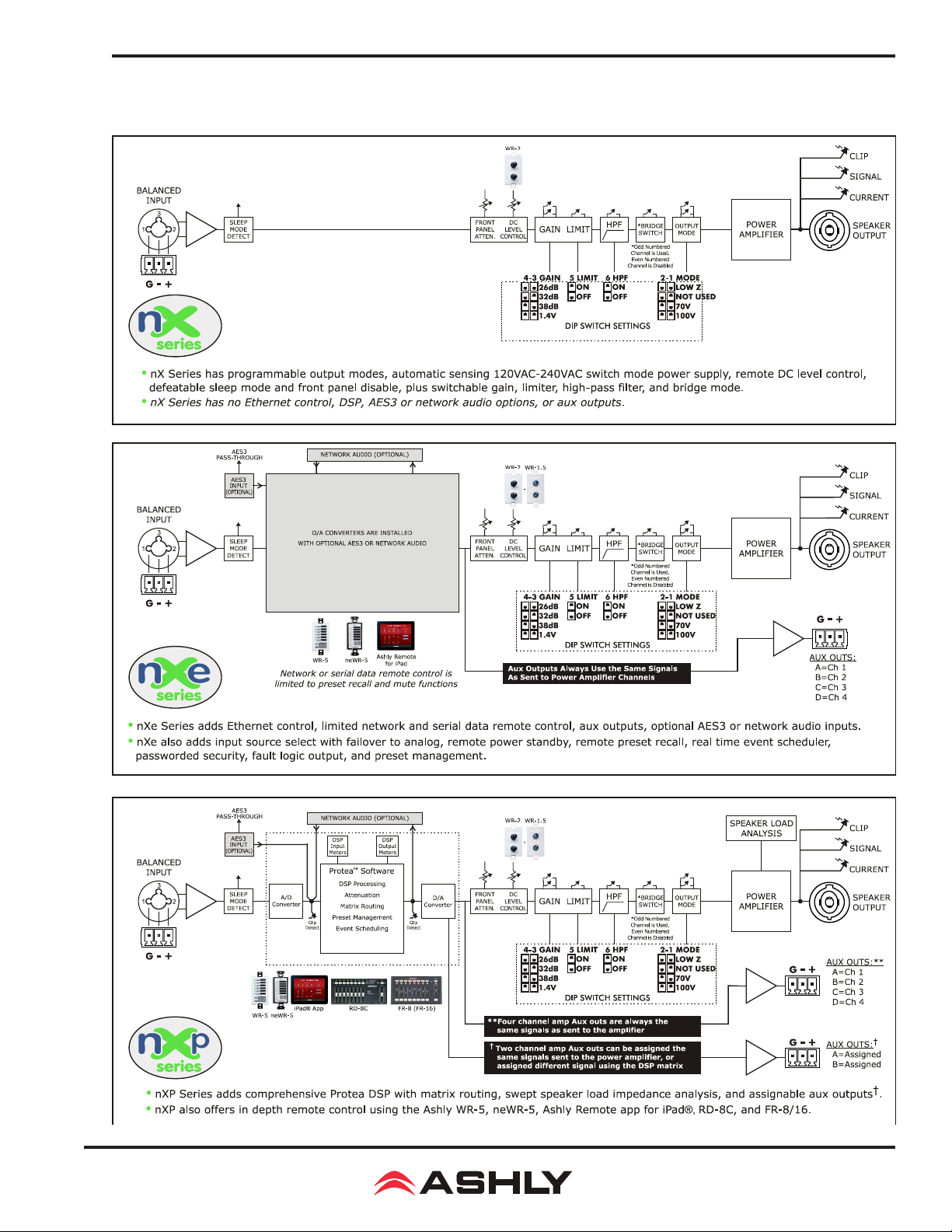
Operating Manual - nX, nXe, and nXp Power Ampliers
17 nX, nXe, and nXp BLOCK DIAGRAMS
59
Page 60

Operating Manual - NX, NXe, and NXp Power Ampliers
ASHLY AUDIO INC. 847 Holt Road Webster, NY 14580-9103, USA
Phone: (585) 872-0010 Fax: (585) 872-0739
Toll Free (800) 828-6308 www.ashly.com
2017-2018 Ashly Audio, Inc. All rights reserved worldwide.
Ashly Audio is a division of Jam Industries, Ltd.
All features, specications, and graphical representations are
subject to change or improvement without notice.
Printed in USA nX 0518 R10
 Loading...