

Page 1
Ashly neWR-5 Remote Control User Reference
Introduction
The neWR-5 is a programmable ethernet based remote control
unit for all Ashly NE (network enabled) products, including NE
processors and NE power amplifi ers. This remote brings control
features such as preset recall/scroll, mute, zone source selection,
individual channel and matrix point level control, and logic output
control throughout a building wherever there is a network connection. All programming is done across the network using Ashly
Protea NE software.
Features
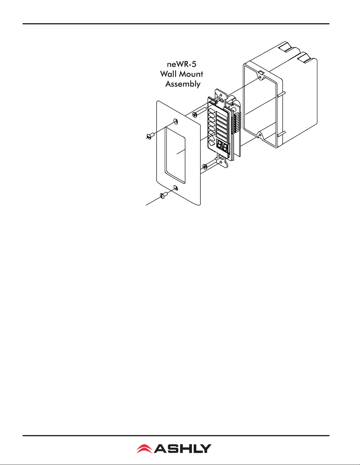
The neWR-5 is designed to mount into a standard North America electrical wall box. A decora cover plate (not included) can be
purchased at hardware stores to cover the neWR-5 electrical box and
satisfy the aesthetic needs of the installation.
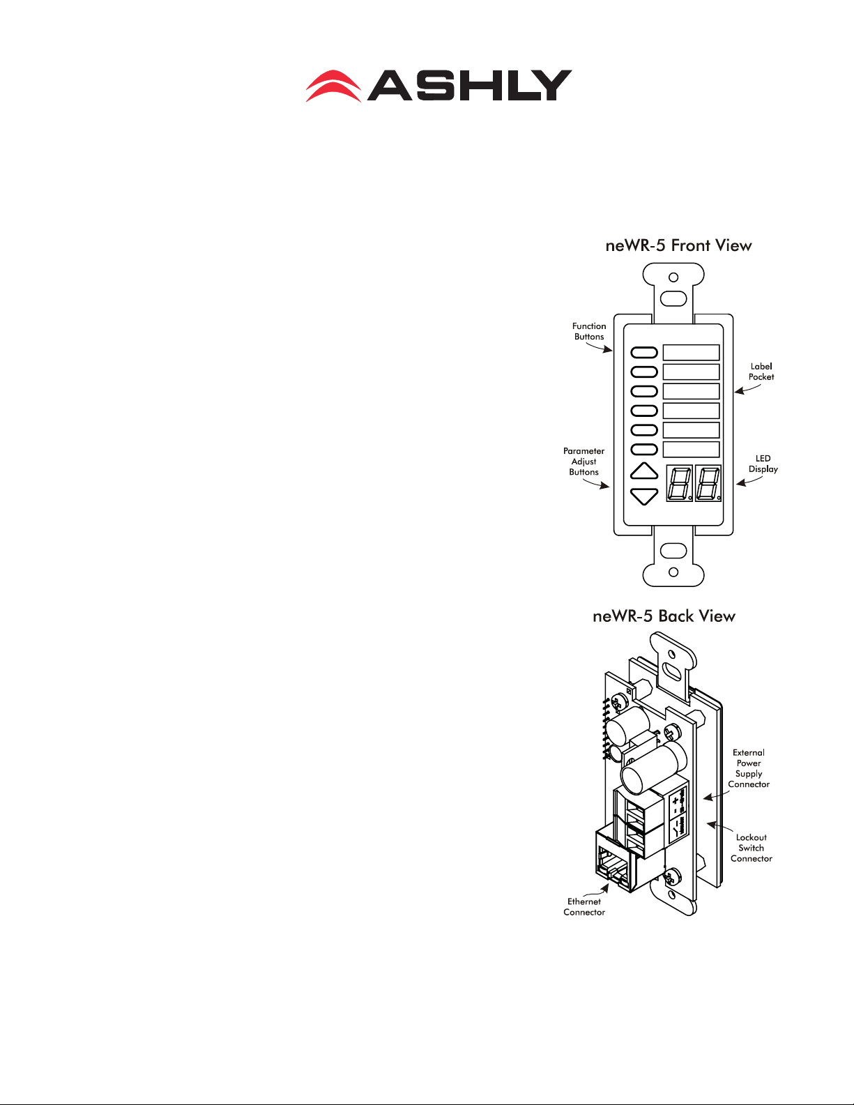
Connecting and powering the neWR-5 is done using standard
Cat-5 ethernet cable and an IEEE 802.3af Power over Ethernet (PoE)
switch, hub, or inline PoE injector. If PoE is unavailable, a 1548VDC power supply capable of at least 2 watts per neWR-5 can be
hard wired to a euroblock connector on the back of the remote.
There is a hard-wired Lock-Out feature on the neWR-5, where
the closing of a switch wired to the lockout euroblock renders all
buttons inactive.
The neWR-5 has six programmable function buttons which can
light up green, red, or amber to display status. To the right of the
function buttons is a pocket in the mylar overlay for a paper function
label to be inserted. The two other buttons are used to adjust function parameters such as gain or preset number, and are indicated by
the LED display.
Hardware Installation
The neWR-5 Ethernet control connection is made using an RJ-45 terminated eight conductor
cable connected directly to a computer, or indirectly over a standard 10/100M Ethernet network.
Maximum cable distance for Ethernet is 100 meters from the nearest hub or switch for copper
Page 2
Operating Manual - neWR-5 Remote Control for NE Products
twisted pair CAT5 cable. If using PoE,
no further power supply is required,
otherwise connect a 15-48VDC power
supply to the neWR-5 via the labelled
euroblock connector. PoE current draw
is 38mA @48VDC.
If desired, wire the Lock Out connector to an external remote or keyed
switch.
Upon connecting and powering
up the system, the WR-5 will have a
“heartbeat”, meaning an internal small
green LED on the PCB (behind the
display bezel) will be fl ashing. After
power up, the LED displays “- -”. If
there is a two-digit number showing in
the display, that means the WR-5 has
been previously programmed to control
a zone and that number is the gain level
for that zone.
Mount the neWR-5 to a wall box as shown (decora plate and wall box not included).
Protea NE Software
Ashly NE products installed on the network will be automatically detected and displayed in
the active device menu tree on the left side of the Protea NE software startup screen. The software
scans for active NE devices every time it loads, but the user can manually scan at any time as well
with <Scan For Devices> at the bottom of the network NE device listing. All NE devices continuously broadcast their availability to the software. All currently connected and active NE products are
highlighted in green, while NE products which have been formerly installed but are currently off-line
or unavailable show up in red.
Individual NE products can be dragged onto the project canvas to simulate physical installation
groups, but editing each product can be done from either the menu tree or the project canvas. Lines,
rectangles, text, and image fi les can be added to create a custom virtual control screen along with NE
products and individual control objects. To see all available canvas tools, right click anywhere over
open canvas. Projects, including all device settings and canvas drawings, can be saved as a fi le.
Checking <Design Mode> (right-click on canvas) allows placed objects to be moved around,
while unchecking <Design Mode> locks objects in place. Once an image has been placed on the
canvas, it must be deleted by hand if that device is no longer available to the software. Scanning for
devices does not automatically remove images which may have been installed at one time but are
now off line. To clear the canvas of all devices and drawn elements click <File - New>. Further
neWR-5 help is available in Protea NE software by navigating through the online help menu.
2
Page 3

Operating Manual - neWR-5 Remote Control for NE Products
Main Control Surface
The main control surface is where the neWR-5 is named, its target NE device gets selected, any
zone defi nition occurs, and where the function buttons are programmed, The neWR-5 comes with
all function buttons set to “Off”. Unlike the WR-5, changes must be saved to the neWR-5 before
becoming effective.
Not all of the button functions listed below are available on all NE products, for instance an
amplifi er will not have “matrix mixer” capability unless it has DSP installed, and some products do
not have logic outputs. Protea NE software is able to determine which functions are available for
neWR-5 control.
1) Off - No function assigned and the button’s LED remains unlit
2) Preset Recall - A single preset number is assigned to a button. When the button is pressed,
the recalled preset number and the letters “PC” (Preset Change) are alternately fl ashed on the WR-5
for fi ve seconds, also locking out any other WR-5 action for that time.
3) Preset Scroll Mode - A range of presets can be assigned to a function button which when
selected, enables the up/down buttons to scroll through the available presets. Upon release of the up/
down button, the currently displayed preset will load. The function button will glow amber for the
duration of the preset scroll operation.
4) Gain Control - Since there are many possible gain adjustment points within a given NE au-
dio processing device, the neWR-5 displayed gain level is only a relative value. In other words, gain
could be changed elsewhere in the target unit, independent from neWR-5 control. The neWR-5 can
adjust gain from 0 to 99, and an upper and lower number limit can be set in the function range section to limit the maximum and minimum reach of that control. To control the gain within the target
device’s input or output signal path, the neWR-5 remote gain function must fi rst be inserted into a
block in the unit’s DSP controls window.
Gain Control over individual channel(s) - When a gain control button is assigned
to control one or more individual channels, pressing that button will cause it to light amber, during
which time the up/down buttons determine gain for the selected channels. If the up/down buttons
remain idle for fi ve seconds, the gain button becomes inactive until being pressed again.
Gain Control over zone - If a zone output is active for that neWR-5, meaning one or
more output checkboxes are selected within the neWR-5 Zone Setup mode, the output gain for that
zone will be shown as the default numerical display, during which time the up/down buttons stay active for that zone’s overall gain control. If a button is assigned for individual input channel(s) gain
control in addition to the neWR-5 being defi ned for output zone control, that button will turn amber
when pressed, and both the neWR-5 up/down buttons and display will refl ect the input channel(s)
gain, reverting back to output zone gain after fi ve seconds of inactivity. If there is no zone output
assigned for the neWR-5, the display shows “--” as the default.
5) Channel Engage/Mute - A button can be confi gured to mute one or more inputs or outputs,
or any combination of the two. The button is green when engaged and red when the selected channels are muted.
3
Page 4

Operating Manual - neWR-5 Remote Control for NE Products
6) Zone Source Selection - This function is used to assign a button to select one or more
inputs for the defi ned zone (Select Zone Outputs) under neWR-5 control. Any function button can
have any combination of inputs as sources. A zone source selection button is green when selected,
and red when unselected. When multiple zone source select buttons are assigned different or overlapping inputs, each button will simply add to or subtract from the other’s input selections. However, if the Exclusive Source Selection box is checked in the zone setup, only the currently selected
button’s inputs will be used for that zone.
The <Disable Zone Level Control> checkbox allows input source selections to be changed from
the neWR-5, but not the overall output gain for that zone. The output gain can still be adjusted from
the target device software, but the neWR-5 user is locked out from making output zone gain changes.
7) Logic Output Active High - This allows the user to toggle the Logic Output assigned pin to
the button. The switch turns green when the output is high.
8) Logic Output Active Low- The switch turns green when the output is Low.
9) Matrix Mixer - This is used to select one or more inputs for the zone under neWR-5 con-
trol, but allows level control of that group at the dsp matrix mixer point instead of the output. Select
one or more Zone Output(s) in the Zone Setup to use the Matrix Mixer function
Security
In addition to the hardware lockout available on the neWR-5, there are multiple user/multiple
levels of software protection assignable to the neWR-5 within the Security tab, from full access to
view only. The security data is stored within the neWR-5 itself, not Protea NE Software. Passwords
are case sensitive. Be sure to write down the password and store in a convenient place for future
reference.
Network Properties
Hardware, device, and device network confi guration details are displayed in the network prop-
erties tab. This includes the current neWR-5 fi rmware revision.
Flash Reprogram
The fi rmware, meaning the internal program which runs on the neWR-5, can be updated easily
over the network. Look in network properties for the current fi rmware revision. To obtain the latest
fi rmware, visit the Ashly Web site, locate and save it to the computer, then run <Flash Reprogram>
under the Device Options menu. The LED displays “Pr” during the reprogramming process.
Factory Reset
To restore factory default settings, a factory reset can be performed by connecting power to the
unit while holding the top function button down for 10 seconds, during which time a countdown will
occur on the LED display. Releasing the button at any time prior to completion of the countdown
stops the process. Upon completion of the countdown, the LED displays “Fr” until the neWR-5 is
reset..
585-872-0010 toll free 800-828-6308 fax 585-872-0739 www.ashly.com
Ashly Audio Inc 847 Holt Rd Webster NY 14580
© 2009 by Ashly Audio Corporation. All rights reserved worldwide.
Printed in USA 1109 R0
 Loading...