

Page 1
ASHLY
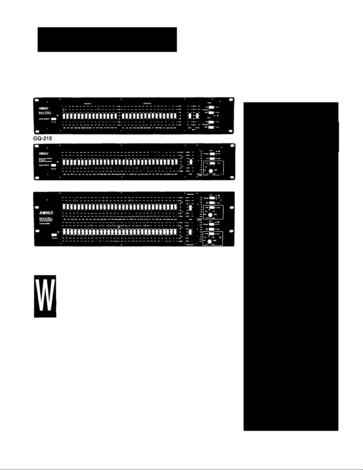
GQ-131
Graphic Equalizers
models GQ-215, GQ-131, GQ-231
Five-Year
Worry-Free Warranty
Detented Metal-Shaft
Fader with Saddle Knob
Precision Wein-bridge
Filters for Accurate
Response and
Low Distortion
Constant "Q" Design
with Low Ripple and
Accurate Response
GQ-231
I hen Ashly set out to design the
GQ-Series, we first thoroughly
re-examined the accepted prin
ciples of graphic equalization.
Extreme accuracy and easeof-use, combined with Ashly's
1
renowned clean, straightfor
ward engineering and design, produce a
series of graphic equalizers that can truly
be called the "next generation."
There are three models available in the
GQ Series. The GQ-215 offers two chan
nels of 2/3-octave, 15-band equalization
and features a peak-indicating LED, a
fixed, swifchable 40Hz subsonic filter,
and a cut or boost range of ±15dB. The
GQ-131 is a mono 1/3-octave, 31-band
equalizer, incorporating a switchable sub
sonic filter that is tunable between 8Hz
and 200Hz, and a boost or cut range of
either ±6dB or ±15dB. Additionally, a nine
position, three color LED level meter and
a peak-indicating LED are provided for
visual reference. The GQ-231 has two
separate channels of 1/3-octave, 31-band
equalization, each incorporating the same
features as the GQ-131.
Ashly's innovations in the GQ-Series
are numerous: New Op-Amps, with high
slew-rate circuitry for the length of the sig
nal path, turn out a clean and virtually
noiseless, transparent sound. A unique
summing system, with low-noise ampli
fiers, is utilized, allowing minimum ripple
and filter interaction. At the detected "flat"
center position, the filters go off-circuit for
an extremely accurate flat response and
absolute minimum noise. There is no
broadening at all near the flat setting.
Our new Q-enhanced Wein-bridge fil
ters are vastly superior to typical R-L-C
and simulated inductor types. Construct
ed of precision metal-film resistors and
polyester capacitors, they produce an
ideal curve shape and precise center fre
quencies with low distortion.
Finally, a unique T-beam front panel
construction eliminates interconnections
between the faders and filters, resulting in
a graphic equalizer with genuine Ashly
innovation, reliability and sonic quality.
The GQ Series, like all Ashly products, is
now fully covered by our exclusive fiveyear worry-free warranty.
Near the "Flat" Setting
Selectable 15dB or
6dB range
(on 31-Band Models)
Switchable-Tunable
Low-Cut Filter
(Switchable 40Hz
Fixed on GQ-215)
9-Position, 3-Color
LED Level Meter (on
31-Band Models) Plus
Peak LED Indicators
Balanced XLR and
Unbalanced 1/4" Inputs
and Outputs
Page 2

Specifications
INPUT
Type:
Impedance:
Max. Level:
OUTPUT
Type:
Min. Load Impedance:
Max. Level:
Frequency Response:
IM Distortion (SMPTE):
THD (20Hz-20kHz):
Equivalent Input Noise
(20Hz-20kHz):
FILTERS
Type:
Number:
Bandwidth:
Tolerance:
Range:
Subsonic Filter:
Power Requirements:
Shipping Weight:
Dimensions:
I/O Connectors:
0
GQ-215
Balanced
20kU
+20dBV
Balanced
600П
+20dBV
±.25dB 20Hz-20kHz
<.01%@ +20dBV
<.01%@+20dBV
-97dBV
Constant Q/Wein-Bridge
2 X 15
2/3 Octave
±2%
±15dB
12dB/Octave @ 40Hz
120VAC, 50-60HZ, 12W
10 lbs
19"Lx3.5"Hx6"D
XLR and 1/4"
GQ-131
Balanced
44kii
+26dBV
Balanced
60oa
+26dBV
±.25dB 20Hz-20kHz
<■01% @ +20dBV
<.01% @ +20dBV
-97dBV
Constant Q/Weln-Bridge
31
1/3 Octave
±2%
±6/15dB ^
12dB/Octave, 6-200Hz
120VAC, 50-60HZ, 12W
10 lbs
19"Lx3.5"Hx6"D
XLR and 1/4"
GQ-231
Balanced
44kii
+26dBV
Balanced
600U
+26dBV
±.25dB 20Hz-20kHz
<.01%@+20dBV
<.01%@+20dBV
-97dBV
Constant Q/Wein-BrIdge
2X31
1/3 Octave
±2%
+6/15d В
12dB/Octave, 8-200Hz
120VAC, 50-60HZ, 12W
15 lbs
19"Lx5.25"Hx6"D
XLR and 1/4"
GQ-215
The graphic cqualiiwr shall be stereo [2-channcls)- Each chanml
shall consist oi 15 bonds centered on standartl ISO Frequencies at
intervals of 2/3 octave aixl covering a ircqucncy ratìge of 251 Iz to
16кНг. Individual bands shall be activated by linear slide faders with
a 45min (ravel, melai actuator shafts and a lacltlc center detent. The
range of equalization per band shall be ±l5dB. The equalizer shall
lijKt a gain of unity with aD sliders centered, and shall have a maximum in/out level of ■t-20dBV. Frequency response sitali be 2.25UD
lOHz to20kllx. Klim ami noise shall be at least -97dDV and SMITE
Inlermodulatlon dtsicrtion or THD shall be less than .01% at ГиД out
put. Input impedance shall be 20kti balanced, lOkll unbalanced.
Oiiiput Impcdmire shall be 200Ì1. Inputs and otilpucs shall be active
(transformerless) balanced type on both XLR and I /4' phone Jacks.
Individual fillers shall be Weln-brtdge type and connected In a sum
ming circuit optimized for mlnltmim filter inlcraetion and constant
bandwidth at any slkler setting. Boost and cut characterlsUcs shall be
fully symmelrlral. with the filter being electrically removed from the
circuit in the center [fiat] pesUion. Indhidual fillers shall be accurate
to within 2% of iiidicaled center frequency and shall be nonadjustabk to Insure Imif:; term accuracy. The equalizer shall also
Include a 12rlR per octave high pass filter at 40Hz. equipped with a
bypass switch. An LED indicator shall show overload conditions.
Input gain shall be adjustable cA'cr a range of tlSdfì. and an overall
EQ bypass switch shall be iiwludcd.Thc equalizer shall weigh 9.5 lbs
net and mmmt In a standard 19' rack using 2 spaces (3.5' high). The
power requirement shall be 1)0-115VAC. 50-60Hz. 12W. Tbe unit
shall bean ASKLYAUDIO GQ-215.
Ashly Audio Inc.
Architect's Specification
GQ-131
Tile graphic equalizer shall be monoaural 11 rhnnnrl). It shall consist
of 31 bands centered on standard ISO irequenefes at Intervals of 1/3
octave and covering a frequency range of 201 tz to 20kKz. Individual
bands shall be activated by liiKar slide faders with a 45nim travel,
metal actuator shafts and a laellle center clelent. Tbr range of equal
ization per band shall be cither ¿€dB or il5dD selected \ia a 2-posllion switch. The equalizer shall have a gain of unity with all sliders
centered, aixl shall have a maximum In/oul le\*el of 426dBV.
Frequency response shall be :.25dB lOHz lo20kHz. Hum and nrHsc
shall be at least -97dBV and SMPTE Intermodulaikm distortion or
Т1Ш shall be less tlian ,01% at full oulpul. Input Impedance shall be
44kD balanced. 22klJ unbalanced. Output Impedance shall be 20ffi}.
Inputs and outputs sitali be active [iransformerlcsvsj halanred type on
both XLR and I/4" phciic jacks. Individual fillers shall be \Veln-bridge
type and coniieded in a summing circuit optimized for minimum filler
interaction and constant bandwidth a( ai^' slkler setting. Boost ami
cut characteristics shall be fully symmetricai. with the filter bcti^
electrically rcnto\*cd frotn the circuit in the ccnlCT (flat) position.
Indiildual filters slull be accurate to within 2% of indicated center
frequency and shall be non-adjuslable to Insure long term accuracy,
The equalizer shall also Include an iSdB per nclair high pass filter
tunable from 8Hz to 200Hz. equipped with a bypass switch. Л 3 color
bar-graph meter shall be employed to show overall output Icwl and
an LED Indicator slial) show overload conditions. Input gain shall be
adjustalile ewer a range Ы* tI5dB. and an overall EQ In-pass switch
shall Ы indudcd.The equalizer shall weigh 9.5 lbs net and mount In a
standard 19' rack using 2 spaces |3.5* high). The power requirement
shall be 110-115VAC. 50-60Hz. I2W. The unit shall be an ASHLY
AUDIO GQ-131.
GQ-231
The graphic equalizer sliall be stereo |2 channels). Each channel
sliall consist of 31 hands centered nn standard ISO frequencies at
intervals of I /3 octave and covering a frequetKy^ range of 20Hz to
20kHz. Irtdhldual bands shall be activated by linear slide faders wltli
a 45mm travel, metal actuator shafts and a tactile center detent. Ilie
range of equalization per band shall be either ±6dB or i 15dB selected
via a 2-posilion switch. The equalizer .shall Itave a gain of unity with
all sliders centered, and shall have a maximum in/oul level of
■»26dBV. Frequency response shall be ±.25dB lOHz lo20kKz. Hum
and ndsc sliall be at Irast -97dHV and SMPTE Itilermodulallcm dis
tortion or THD shall be less tlian .01% at full output. Input
tinpedanre shall bo 44kil balanced. 22kfl unbalanced. Output
Impedance shall be 20011. Inputs and outputs aluill be active [Inuisformcrlcss) balanced hpr on both XIJI and 1/4* phorw [ocks.
liKlividual filters shall be Weln-brfdge type and connected in a sum
ming circuit optimized for minimum filter Interaction and constant
bandwidth at any slkler setting. Boost and cut characteristics sliall be
fully symmetrical, with Ihe filter being electrically rcmo\’cd from the
circuit in the center (Flail position. IndMdual flllrrs shall be accurate
to within 2% of indicated center frequency and sliall be iiaiodjustabk to insure long term accuracy. T|w equalizer shall also
Include an l8dB per octave high pass filter lunabk from 8Hz to
2O0liz. equipped with a bypass switch. A 3 color bar-graph meter
shall be employed to show overall output k’v'cl and an LED indlcaior
shall show* overload coiKlitions. Input gain shall be adjustable mrr a
range of :l5dB. and an overall EQ liypass switch shall be included.
The equalizer shall weigh )3lbs net and mount in a standard 19' rack
using 3 spaces (5.25" hlgh|. The power requirement shall be 110-
115VAC, 50-601 Iz, 2CW. Hie unit shall be an ASHLY AUDIO OQ-23!,
Since 1972
© 1990 Ashly Audio
 Loading...