

Page 1
FET.1sOOM
FET-1500C
PowerAmplifiers
model FET-I500M
model FET-I500C
professional
shly, the
audio
MOS-FET
a
proud
is
generation,
Series.
decade, our original
Series
applications
excellence
now improve upon that
offering more models
cations than
The FET-1500
variations:
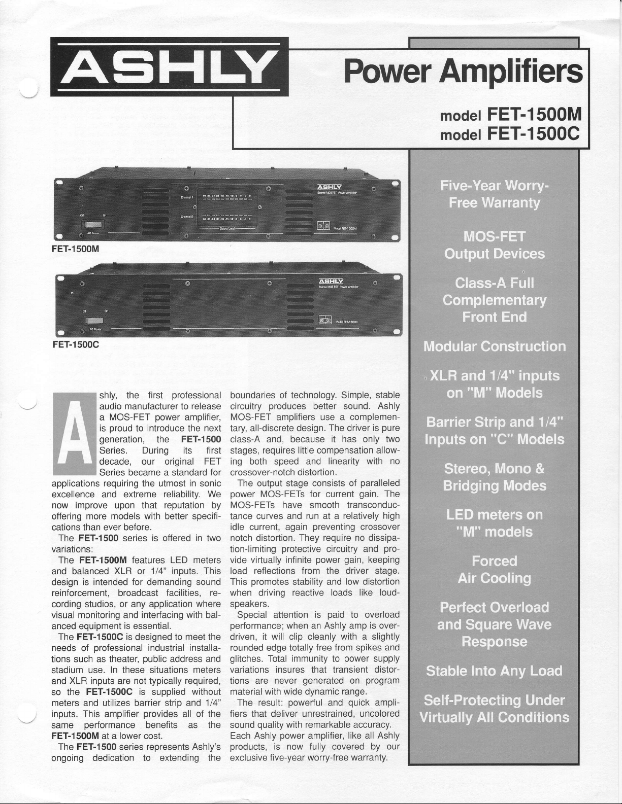
The FET-1500M features LED meters
and balanced
design
reinforcement, broadcast facilities, recording studios,
visual monitoring
anced equipment
The FET-1500G is
needs of
tions
stadium
XLR inputs are
and
so the
meters and utilizes barrier strip and
inputs.
same
FET-1500M at a
The FET-1500 series
ongoing dedication
requiring
and extreme
ever before.
XLR or 1/4"
is intended for demanding sound
professional
such as theater,
use. In these situations
FET-1500C is supplied
This
amplifier
performance
first
manufacturer
power
introduce the next
to
the
During its first
became
utmost in sonic
the
with
is offered in
series
or any application
interfacing with bal-
and
is essential.
designed to
industrial installa-
public
not
typically
provides
benefits as the
lower
cost.
represents Ashly's
to extending the
release
to
amplifier,
FET-I500
a standard
reliability. We
reputation
better specifi-
inputs.
where
meet
address and
meters
required,
without
all of the
FET
for
by
two
This
the
1/4"
boundaries
circuitry
MOS-FET
tary, all-discrete design.
class-A and, because
stages,
ing both speed and
crossover-notch distortion.
The
power
MOS-FETs have smooth transconductance curves and
idle current, again
notch
tion-limiting
vide virtually infinite
load reflections from the driver stage.
This
when
speakers.
Special attention
performance;
driven,
rounded edge totally
glitches.
variations insures that transient distortions are
material with wide dynamic
The result:
fiers that deliver unrestrained, uncolored
sound
Each Ashly
products,
exclusive
of technology. Simple, stable
produces
amplifiers
requires little
output stage consists
MOS-FETs for current
distortion.
protective
promotes
driving
it will
Total immunity
never
quality
power
is
five-year
better sound.
use a complemen-
The
it has only two
compensation
linearity with no
run
at a
preventing
require
They
circuitry and
power gain,
stability and
reactive loads
paid
is
when an Ashly amp
clip cleanly
generated
powerful
with remarkable
amplifier,
now fully
worry-free warranty.
with a slightly
free from
to
and
covered by
Ashly
pure
is
driver
allow-
paralleled
of
gain.
The
relatively high
crossover
no dissipa-
pro-
keeping
low
distortion
like loud-
to overload
is
over-
and
spikes
power
supply
program
on
range.
quick
ampli-
accuracy.
like
Ashly
all
our
Page 2
ifications
Arch itect's
Ashly Model l5O0M
power
The
minimum
loads or 275 watts
channels operating. When switched into bridged mono
node. it shall deliver at least 550 watts into m 8 ohm
load. The amplifier
shorted. open, or mismatched
have a
sitiviqr of 1.3 Volts ! 20/o lor lull rated output.
response shall be 10Hz Io 2OkHz t .5d8. It shall be
into any load including
Hum and noise shall be at least 110d8
and SMPTE intermodulation distoftion shall be less
.010/o at full output. The
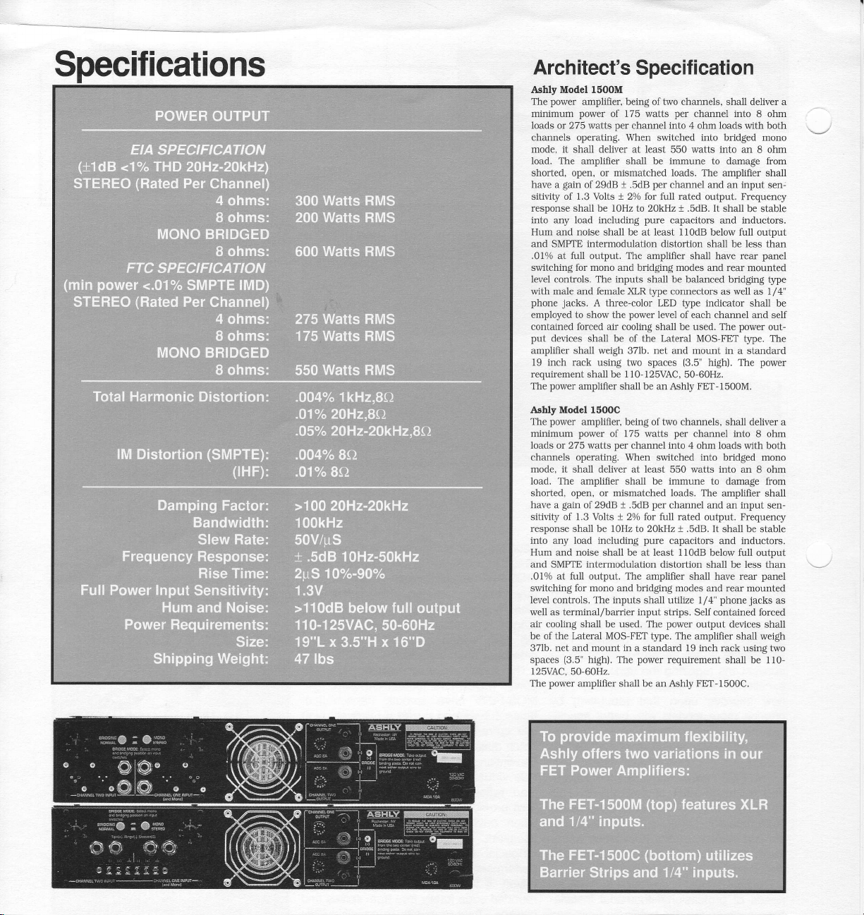
switching for mono and bridging modes and rear mounted
level controls. The inputs shall be balanced bridging type
with male and female XLR type connectors as well as 1/4"
phone
employed to show
contained
put
anplifier shall lveigh 371b. net and mount in a
19 inch rack using two spaces
requirement shall be 1 10 125VAC.
The
Ashly Model 1500C
'Ile
minimum
loads or 275 watis
channcls operating. When switched into
mode. it shall deliver al leasi
load. The amplifier
shoried, open. or nisnratched loads. The amplifier shall
have a
sitivily of 1.3 Volts t 20/o lor ltll rated output. F-requency
response shall be 1OLIz to 2OkHz, t .5dts. It shall be stable
inlo irny
IIum :rnd noise shall bc at lcast I 1Odts below llll
ancl SMPI'E intermodulation clistortion shall be less
.010/o at Iull output. Thc amplilier shall have rear
swikrhing lbr rrono and bridgine modes and rear
level controls. The inputs
well as terminal/barricr input strips.
air cooling shall be used.
be ol the
371b.
spaces
l2SVAC.
The
amplifier. being oftwo
power
gain
of 29dB t .5dB
jacks.
forced
devlces
shall be of the Lateral MOS FET
porver
amplitier shall be an Ashly
power
amplilier, being of two channels,
power
gain
oi29dB t .SdB
lo:rd
Lateral
net
mouni
and
(3.5'
high), The
50-60H2.
power
amplilier shall
Specif
oI 175 watts
per
channel into 4 ohm loads with both
shall be
pure
amplifier shall have rear
A three-color LED type indicator shall be
power
the
air cooling shall be used. The
ol 175 watts
per
channel into 4 ohn loads wiLh
shnll be imntune to dam:rge liom
inclllding
pure
shall utilize 1/4'
'l'he
MOS-FET type. The nmplilier shall weigh
in a stanclard l9 inch rack usinq two
power
be
ication
channels, shall deliver a
per
channel into 8 ohm
immune
to damage from
loads.
per
level
per
an Ashly FET-
The amplifier shall
channel and
capacitors and inductors.
of each chamel and self
(3.5"
50 60H2.
FET- 1500M.
per
channel into 8 ohm
watts
550
ch:rnnel and an input sen-
capacitors and inductors.
Sell conLait.red lbrced
porver
output dcvices shall
requirement shall be 110-
input
an
Frequency
below full output
power
fpe.
high). The
shall deliver a
bridged mono
into an 8 ohm
phonc.jacks
I 500C.
sen-
stable
than
panel
out-
The
standard
power
both
output
than
panel
ntounted
as
 Loading...