

Ashland I-900 User Manual Ver10-2008
I-900
PARTS MANUAL
Ver. 0109- 22079
Ashland Industries Inc.
1115 Rail Drive
P.O. Box 717
Ashland, WI. 54806
Ph: 877-634-4622 Toll Free
Ph: 715-682-4622
Fx: 715-682-9717
www.ashlandind.com
I-900
T
g
g
T
WELCOME TO OUR NEW CUSTOMERS!
hank you for your purc hase of an Ashland scraper and the confidence you have placed in us to
handle your earthmoving projects. Years of research, testing and successful applica tion have
been spen t to ensure qu ali ty and maximum performance fo r our cus t omers. Ple ase read and
understand this manual before attempting to attach or operate this scraper. This manual should
always rema i n with the machi ne . Be sure and fill out and send in the owners re
the beginning of this manual, or you may fill out the form on-line by
cli ck on “Register yo ur Machine” at the bott om of the pag e.
oing to ashl andind .com and
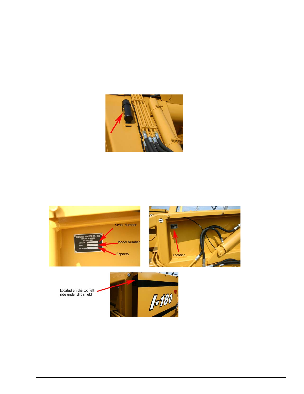
SC RAP E R ID NUMBE R
he se rial numbe r plate for th e sc ra pe r is loca ted on the right rear area of t he scraper
underneath the dirt shield. The letter and numbers stamped identify the serial number, model
number and c a pacity of the scraper. Please re cord this serial number for use in or dering parts,
warrantee issues and to trace your equipment if it is ever stolen.
istration form at
Ashland Industries Toll-free:877-634-4622 Fax:715-682-9717
Page #1

I-900
A
How to Order Parts
HOW TO OR DE R P A R T S :
IMPORTANT
Parts must be ordered through your l ocal authorized ASHLAN D dealer.
Be sure to state MODEL and SERIAL NUMBER of your machine, PAR T NU MBER, DESCRIPTIO N
and QUANTI TY needed.
Unless this is done, we cannot provide prompt service or assure shipment of the correct
parts.
shlan d Industries weldable replace ment par ts are available to rebuild, modify or upd ate your
s crap e r to curr ent fa c t ory s pe ci fi cat ion s.
Page 3. Safety Guidelines
Page 4-5. Operators and Maintenance Instructions
Page 6. Illustration Assembly
Page 7. Gooseneck Frame Assembly – Illu stration and Parts
Page 8. Apron Assembly – I llustration and P arts
Page 9. Bowl & Frame Assembly – Illust ration and Parts
Page 10. Push Off Gate Assembly – Illustration and Parts
Page 11. Pole and Axle Assembly – Illustration and Parts
Page 12. Wheel, Hub and Spindle – Illustration and Parts
Page 13. Hydraulic Cylinder (Dig & Lift) 4” X 16”
Page 14. Hydraulic Cylinder (Apron –right & left) 3 ½” X 10”
Page 15. Hydraulic Cylinder – (Pushgate) 4” X 50”
Page 16-19. Hydraulic Plumbing
Page 20-22. Hydraulic Manifold
Page 23. Warranty Statement
INDEX
Ashland Industries Toll-free:877-634-4622 Fax:715-682-9717
Page #2

I-900
,
SAFETY SIG NAL WORD S
ote the use of t he signal words DANGER, WARNING and CAUTION with the safety messages. The appropriate
ignal word for each has b een selected using the following guidelines:
DANGER: Indicates an imminently hazardous situation tha t, if not avoid ed, will result in death or
erious injury. This signal word is to be limited to the most extreme situati ons typi cally for machine comp onents
hich, for functional purposes, cannot be guarded.
WARNING: Indicates a potentially hazardous situation that, if not avoided, could result in de ath or
serious injury, and includes haz ards that are expos ed when guards are removed. It may also be used to
alert against unsafe practices.
CAUTION: Indicates a potentially hazardous situation that, if not avoided, may result in minor or
mod erat e injur y . It ma y al so be use d to alert again st unsafe practices.
GENERAL SAFETY GUIDELINES
afety of the operator is one of the main concerns in designing and develo ping a new piece of equipm ent.
esigners and manufacturers build in as many safety features as possible. However, every year many accidents
ccur which could have been avoided by a few seconds of thought and a more careful approach to handling
quipment. You, the operator, can avoid many a ccidents by observing the following precautions in this section.
o avoid personal injury, study the following precaut ion s a nd insist t hose wo rki ng with you, or for you, follow
hem.
eplace any CAUTION, WARNING, DANGER or instruction safety decal that is not readable or is missing.
ocation of such de cals is indic ated in this bookle t.
o not at t empt to operate this e qu ipment un der the in fluence of drugs or alc o h ol.
eview the safety instr uctions with all users annually.
his equipment is danger ous to ch ildren and person s unfam iliar w ith its op eration. The operator shou ld be a
esponsible adult familiar with farm machinery and trained in this equipment’s operations. Do not allo w
ersons to operate or assemb le this unit until they have read this manual and have developed a
horough und ers ta nding of the safety pr ecau ti on s an d of how it work s.
o p revent injury or d eat h, us e a t r actor equipped with a Roll Ov er Prot ect ive System ( ROPS ). Do no t paint over
emove or deface any safety signs or warning decals on your equipment. O bserve all safety signs and practice
he ins tructions on them.
ever ex ceed the limit s of a piece of ma chi nery. If its ability to do a job, o r to do so safely, is in question -
ON ’T TRY IT.
Ashland Industries Toll-free:877-634-4622 Fax:715-682-9717
Page #3

I-900
T
g
.
OPERATORS AND MAINTENANCE INSTRUCTIONS
his scr aper is a durable piece of equipment and with proper care will yield many years of trouble free
operation. The scraper requires a power source with TWO 4 way (double actin
The scraper should be greased at all points where grease fittings are provided. Conne ct hydraulic
hoses to the tractor and retract lift cylinde rs to REMOVE TRANSPORT LOCK PINS, then extend and
retract all cylinders several times to force out an y air from the hydraulic cylinders and lines. Check the oil
levels in the tractor hydraulic system and add to maintain the proper level. Care should be use d when
addin g oil or when disconne cting any oi l line to keep a ll dirt out of the oil as dirt is a major factor in t he
fa ilure of hy drau lic component s .
When th e scraper is placed into operat ion , t he operator will have to “feel out” the amount of dept h of
cut to ob tain maximum loading e fficiency. This is usually ac complished by taking a lesser and more
uniform cut; howe ver, some soil co nditions such as loose sand may require a “pumping action” obtained
by taking succes sive d eep cuts and lifting out of cut as the tractor b egins to lose pow er or tra ction.
1. After 1 0 hours work, all bo lts should be checked and tightened if necessary.
2. Every 10 hours all grease fittings should be lubricate d.
3. After 50 hours work, all bolts should be rechecked and tightened if necessary. Check wheel
bearings and adjust if necessary.
4. After 300 hours work, clean and repack whe el bearings and replace, if neces sary, cutting edg e s,
worn pins, etc.
) hydr aulic control valves
Ashland Industries Toll-free:877-634-4622 Fax:715-682-9717
Page #4

I-900
V
g
WARNING
Check Tires and Wheels
The task of servi ci n g tires and wheel s can be ex tr emely dang ero us and should be
per formed by tr ai ne d pe r so n nel only, using the cor r e ct tools and following spe cific
procedures. Do not attempt to mount, demount or inflate a ti re if you do not have
the pro per equipme nt an d ex perien ce to perform the job. Call a qualif ied repa ir
ser vice to in spe ct the ass embly an d make neces sary repa ir s. Failure to heed
warnings could lead to serious injury or death.
isually inspect tires and wheels daily. Carefully inspect any rim and tire assem bly that has been
run underin fla ted or fl at before reinfl at ing th e t ire t o m ake sur e th ere is n o damage t o either t he
rim or t ire.
• ALWA Y S w ear person al protect io n equ ipment such as gl ov es, foot wear, eye protect ion ,
hear i ng p rot ection and head gear when servici ng ti re and wheel co m pon ents.
• DO NOT o perate with damaged rims, tire c uts or bubbles, missing lug bolts or nuts o r
damage d rim s.
• ALWAYS maintain th e correct tire press ure. NEVER exceed recommended ti re inflat ion
pres su re .
• INSPEC T any rim and t ire assembl y t hat has be en ru n f lat or severely underinflated
before reinflating the tire. Damage to the rim and tire may have developed.
• NEVER reinfla te a tire that has lost air pressure or has been run flat witho ut determi ning
and corr ec ting the problem.
• NEVER try to repair wheel, rim, or tire components parts. Parts that are cracked,worn,
p itted with corro sio n, o r damaged m ust be disc arded, a nd r eplaced w ith goo d parts.
• ALWAYS use approved tire and rim combinations for the model scraper that you have
and verify that part numbers of c omponents are co rrectly matched for the assembly.
• ALWAYS ex haust all air from the tire prior to demounting.
• ALWAYS place wheel and tire assemblies in restraining devices (safety cage) when
inflating tires. Use a clip-on chuck and long extension hose to allow you to stand to the
si de of the tire and not in front of it.
• NEVER weld o r cut on an infl at ed t ire assembl y. Weldin g h eat can cause inc reased
pressure whic h could result in tire explosion.
• ALWAYS use proper lifting techniques, and mechanized lifting aids to move heavy
com ponents and assemblies.
• NEV ER leav e a tir e, wheel, or as sembly unsecu red in a vertical position.
• ALWAYS take care wh en mov in g tires and wheels that other peop le in th e area are not
endan
ered .
Ashland Industries Toll-free:877-634-4622 Fax:715-682-9717
Page #5

I-900
Illustration Assembly
Ashland Industries Toll-free:877-634-4622 Fax:715-682-9717
Page #6

I-900
Gooseneck Assembly
Key Number Part Number Description
1 A9057 Gooseneck Frame
2 8110 Lock washer 5/8"
3 7536 Nut, 5/8" NF
4 A90004 Cast Socket half, rear
5 A90005 Cast Socket half, front with zerk hole
6 A2206 Grease Zerk, Long Shank
7 AFB-00043 Bolt, 5/8" x 4 1/2" NF
8 OPT-00001 Hitch Jack
9 AHF-00028 Grease Fitting 90° 1/8 NPT
10 AFB-00018 Bolt: 1"NC X 3" Gr 8
11 AFW-00001 Washer 1" Flat
12 AFN-00012 Nut: 1" NC Gr 8
Ashland Industries Toll-free:877-634-4622 Fax:715-682-9717
Page #7
 Loading...