


EARTHMOVERS
QualityEquipment since 1953
I-180TS
PARTS MANUAL
Version 5-06 SN: 21220 and Up
Ashland Industries Inc. 1115 Rail Drive
P.O. Box 717 Ashland, WI. 54806
877-634-4622 Toll Free - phone
715-682-4622 phone
715-682-9717 fax www.ashlandind.com
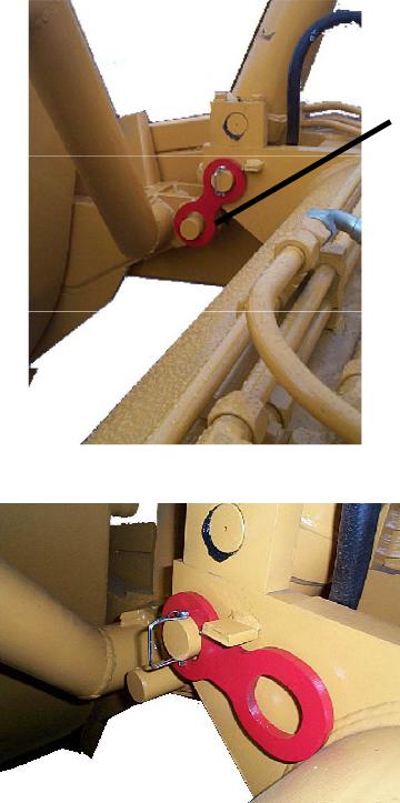
IMPORTANT
Please locate red Transport Links and remove prior to operation. Retract Lift Cylinder Circuit, Remove Safety Snap Pin, Remove link and replace into storage position as shown in figure 2.
Reinstall Safety Snap Pins.

EARTHMOVERS
Model I-180TS Scraper
HOW TO ORDER PARTS:
IMPORTANT
Parts must be ordered through your local authorized ASHLAND dealer.
Be sure to state MODEL and SERIAL NUMBER of your machine, PART NUMBER, DESCRIPTION and QUANTITY needed.
Unless this is done, we cannot provide prompt service or assure shipment of the correct parts.
Ashland Industries weldable replacement parts are availabe to rebuild, modify or update your scraper to current factory specifications.
|
|
INDEX |
Page |
4. |
Operators and Maintenance Instructions |
Page |
5. |
Safety Guidelines |
Page |
6. |
Illustration - Assembly |
Page |
7. |
Complete Yoke Type Hitch |
Page |
8-9. |
Swivel Hitch Assembly |
Page |
10. |
Front Section Frame |
Page |
11. |
Lift Cylinder 5-1/2 x 20 |
Page |
12. |
Lift Cylinder 5 x 20 |
Page |
13. |
Apron Assembly |
Page |
14. |
Apron Cylinder old style |
Page |
15. |
Apron Cylinder new style |
Page |
16-17 |
Bowl and Frame Assembly |
Page |
18. |
Push Off Gate Assembly |
Page |
19. |
Push Off Cylinder |
Page |
20. |
Wheel Assembly |
Page |
21. |
Front Section |
Page |
22-27 |
Hydraulic Plumbing |
Page |
28-33 |
Identification, Illustration, Parts List and Adjustment - Hydraulic Valve |
Page |
34. |
Hydraulic Schmetic |
Page |
35-36 |
Grease Locations |
Page |
37-40 |
Service Manual Appendix |
Page |
41. |
Warranty Statement |
OPERATORS AND MAINTENANCE INSTRUCTIONS
This scraper is a durable piece of equipment and with proper care will yield many years of trouble free operation. The scraper requires a power source with TWO 4 way (double acting) hydraulic control valves.
The scraper should be greased at all points where grease fittings are provided. Connect hydraulic hoses to the tractor and retract lift cylinders to REMOVE TRANSPORT LOCK PINS (point A), then extend and retract all cylinders several times to force out any air from the hydraulic cylinders and lines. Check the oil levels in the tractor hydraulic system and add to maintain the proper level. Care should be used when adding oil or when disconnecting any oil line to keep all dirt out of the oil as dirt is a major factor in the failure of hydraulic components.
When the scraper is placed into operation, the operator will have to “feel out” the amount of depth of cut to obtain maximum loading efficiency. This is usually accomplished by taking a lesser and more uniform cut; however, some soil conditions such as loose sand may require a “pumping action” obtained by taking successive deep cuts and lifting out of cut as the tractor begins to lose power or traction.
1.After 10 hours work, all bolts should be checked and tightened if necessary.
2.Every 10 hours all grease fittings should be lubricated.
3.After 50 hours work, all bolts should be rechecked and tightened if necessary. Check wheel bearings and adjust if necessary.
4.After 300 hours work, clean and repack wheel bearings and replace, if necessary, cutting edges, worn pins, etc.
5.Maintain tire pressure at 45 to 50 psi.

SAFETY SIGNAL WORDS
Note the use of the signal words DANGER, WARNING and CAUTION with the safety messages. The appropriate signal word for each has been selected using the following guidelines:
DANGER: Indicates an imminently hazardous situation that, if not avoided, will result in death or serious injury. This signal word is to be limited to the most extreme situa-
tions typically for machine components which, for functional purposes, cannot be guarded.
WARNING: Indicates a potentially hazardous situation that, if not avoided, could result in death or serious injury, and includes hazards that are exposed when guards are removed. It may also be used to alert against unsafe practices.
 CAUTION: Indicates a potentially hazardous situation that, if not avoided, may result in minor or
  moderate injury. It may also be used to alert against unsafe practices.
GENERAL SAFETY GUIDELINES
Safety of the operator is one of the main concerns in designing and developing a new piece of equipment. Designers and manufacturers build in as many safety features as possible. However, every year many accidents occur which could have been avoided by a few seconds of thought and a more careful approach to handling equipment. You, the operator, can avoid many accidents by observing the following precautions in this section. To avoid personal injury, study the following precautions and insist those working with you, or for you, follow them.
Replace any CAUTION, WARNING, DANGER or instruction safety decal that is not readable or is missing. Location of such decals is indicated in this booklet.
Do not attempt to operate this equipment under the influence of drugs or alcohol.
Review the safety instructions with all users annually.
This equipment is dangerous to children and persons unfamiliar with its operation. The operator should be a responsible adult familiar with farm machinery and trained in this equipment’s operations. Do not allow persons to operate or assemble this unit until they have read this manual and have developed a thorough understanding of the safety precautions and of how it works.
To prevent injury or death, use a tractor equipped with a Roll Over Protective System (ROPS). Do not paint over, remove or deface any safety signs or warning decals on your equipment. Observe all safety signs and practice the instructions on them.
Never exceed the limits of a piece of machinery. If its ability to do a job, or to do so safely, is in question - DON’T TRY IT.

page_02-icon.eps
A125056
Complete Yoke Type Hitch
Implemented April 2003
KEY NO. |
PART NO. |
DESCRIPTION |
2. |
A125056-02 |
UTIL HITCH BRKT |
3. |
A125056-03 |
MDU HITCH PIN |
4. |
A125056-04 |
MDU HITCH SWIVEL |
5. |
A125056-05 |
19C 18D HITCH CAP |
6. |
A125056-06 |
19C 18D WASHER SWIVEL HITCH |
7. |
A125056-07 |
BOLT: 3/4 X 3 HEX GR 8 |
8. |
A125056-08 |
WASHER: FLAT - 3/4 HARD F-436 |
9. |
A125056-09 |
WASHER: FKAT-2-1/2 HARD F-436 |
10. |
A125056-10 |
WASHER: FLAT-1-1/2 HARD F-436 |
11. |
A125056-11 |
NUT: SLOTTED 1-1/2 COARSE |
12. |
A125056-12 |
PIN: COTTER 5/16 X 2-1/2 |
13. |
A125056-13 |
19C 18D SWIVEL HITCH CAP SEAL |
22. |
A125056-22 |
BUSHING: 275250187 |
23. |
A125056-23 |
REYNOLDS UTILITY HITCH YOKE |
24. |
A125056-24 |
BUSHING: 175150150 |
25. |
A125056-25 |
ZERK - STRAIGHT |
26. |
A125056-26 |
ZERK - 90 DEGREE |
27. |
A125056-27 |
BUSHING: 300251200 |
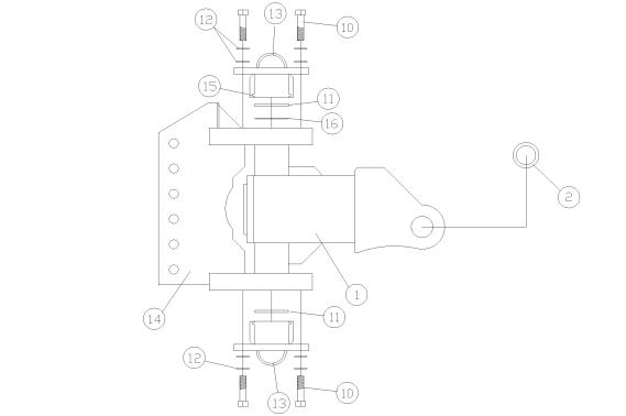
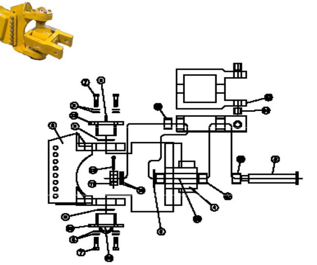
SUPER CAPACITY SWIVEL HITCH ASSEMBLY
A125057
COMPLETE HITCH: H.D. ICON 360 DEG. SWIVEL
ITEM |
QTY |
PART NUMBER |
DESCRIPTION |
1 |
1 |
A125057-01 |
Swivel Hitch Yoke |
2 |
2 |
A125057-02 |
Bushing, 1-1/2” ID, Reynolds Spec. |
10 |
8 |
A125057-02JD |
Bushing, 60 mm ID, John Deere Spec. |
AFB-00064 |
HHCS: 3/4 NC X 3” GR. 8 ZINC |
||
11 |
2 |
A125056-06 |
WASHER: FOR ICON HITCH CAP |
12 |
16 |
AFW-00007 |
WASHER: FLAT 3/4” ZINC USS |
13 |
2 |
A125057-13 |
HITCH CAP, ICON |
14 |
1 |
A125057-14 |
SWIVEL HITCH BRACKET, 7 HOLE |
15 |
2 |
A125057-15 |
SEAL, HITCH CAP |
16 |
1 |
A125057-16 |
SHIM, HITCH CAP |
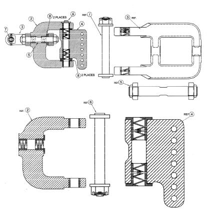
SUPER SWIVEL HITCH ASSEMBLY
Used on Units upto March 2003
KEY NO. |
PART NO. |
DESCRIPTION |
|
1. |
A1063527 |
Super Yoke hitch, Includes 2 & 3, (w/o 4,6,7 & 1 ea. |
|
|
|
of 8) (Required 1) |
|
2. |
A1062280 |
Rear Super Yoke, Assembly (1 required) |
|
|
A1063177 |
Bushing ( 2 required) |
|
|
A1063144 |
Bushing, Spiral (2 required) |
|
|
14505 |
Fitting, Grease (2 required) |
|
3. |
A1063281 |
Front Super Yoke, Assembly (1 required) |
|
|
A1063145 |
Busing, Spiral (2 required) |
|
|
14505 |
Fitting, Grease (2 required) |
|
4. |
A1063688 |
Pivot Pin Housing, Assembly (1 required) |
|
|
A1063143 |
Bushing, Spiral (2 required) |
|
|
14505 |
Fitting, Grease (2 required) |
|
5. |
A1063283 |
Pin, Horizontal Assembly with Nuts (1 required) |
|
|
A1063212 |
Pin only (1 required) |
|
|
A1044362 |
Nut, Lock Nylon, 2-12 UNF (2 required) |
|
6. |
A1063284 |
Pin, Vertical Assembly with nut,wash,c.pin (1 required) |
|
|
A1063214 |
Pin only (1 required) |
|
|
A1063259 |
Washer (1 required) |
|
|
ARF03024-00260 |
Nut, Slotted. Hex 2.00 NC G5 (1 required) |
|
|
ARF06020-00083 |
Pin, Cotter .375” x 4.00” (1 required) |
|
7. |
AB581 |
Hitch Pin, Assembly (1 required) |
|
|
AB580 |
Pin Weldment (1 requried) |
|
|
AB195 |
Washer, 3.00”OD x 1.56” (1 required) |
|
|
AFN-00014 |
Nut, Slotted, 1.5” NC G5 (1 required) |
|
|
ARF06020-00060 |
Pin, Cotter |
|
8. |
A1063146 |
Washer, Thrust (4 required) |
|
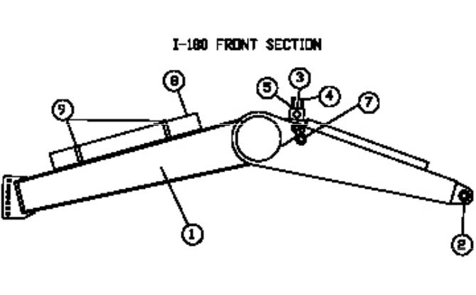
I-180TS Front Section Frame
A123320
ITEM |
QTY |
PART NUMBER |
DESCRIPTION |
|
1 |
1 |
A123320 |
Front Section |
|
2 |
2 |
A123320-8 |
2” ID x 3-1/2” OD x 3” long bronze |
|
|
|
|
bushing |
|
3 |
4 |
A123293A |
Trunion mount block |
|
4 |
8 |
AFB-00039 |
Bolt, 3/4” NC x 5-1/2” long, gr. 8 |
|
5 |
8 |
AFW-00002 |
3/4” lock washer |
|
7 |
2 |
A123320-20 |
Travel Lock |
|
8 |
1 |
A125005 |
Accumulator |
|
9 |
2 |
A125009 |
Mounting brackets |
|
10
MODEL I-180
LIFT CYLINDER 5 1/2 X 20
PART NO. A125044
*** Dealer Note ***
KEY NO. PART NO. |
DESCRIPTION |
1.A123326-1
2.A125044-02
3.AFN-00018
4.A125044-04
5.A125044-05
6.A123324-6
7.A123324-5
8.A125044-10
9.A125044-15
10.A123324-10
11.A125044-20
12.A123324-7
A125044-40
13.A123335
14.AFP-00001
Piston Rod: 2-1/2” Barrel Weldment, 5-1/2” Nut: Lock 1-1/2-12 Piston, 5-1/2”
Gland, 5-1/2” Rod Seal
Wear Band ID for Gland Wear Ring, 5-1/2” Piston Seal, 5-1/2” O-Ring, ID of Piston O-Ring, OD of Gland Rod Wiper
Seal Kit (Items 6-12) Pin, 2” x 10-1/2” lg. Cotter Pin, 1-4” x 3”
*** Dealer Note ***
Some 2002 models used a 5” x 20” lift cylinders in lieu of this cylinder. To ensure correct parts shipment carefully examine the cylinder for size.
|
5-1/2” x 20” |
5” x 20” (p.n. A123326) |
Barrel Circumference |
19-1/4” |
17-1/2” |
Barrel Diameter |
6” |
5-1/2” |
11
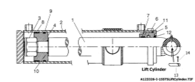
LIFT CYLINDER 5 X 20”
PART NO. A123326
*** Dealer Note ***
KEY NO. |
PART NO. |
DESCRIPTION |
1. |
A123326-1 |
Piston Rod: 2-1/2” |
2. |
A123326-2 |
Barrel Weldment |
3. |
AFN-00018 |
Nut: Lock 1-1/2-12 |
4. |
A123324-4 |
Piston |
5. |
A123324-3 |
Gland |
6. |
A123324-6 |
Rod Seal |
7. |
A123324-5 |
Wear Band |
8. |
A123324-8 |
Wear Ring |
9. |
A123324-9 |
Piston Seal |
10. |
A123324-10 |
O-Ring |
11. |
A123324-11 |
O-Ring |
12. |
A123324-7 |
Rod Wiper |
|
AHS-00140 |
Seal Kit (Items 6-12) |
13. |
A123335 |
Pin, 2” x 10-1/2” lg. |
14. |
AFP-00001 |
Cotter Pin, 1-4” x 3” |
*** Dealer Note ***
Some 2002 models used a 5” x 20” lift cylinders in lieu of this cylinder. To ensure correct parts shipment carefully examine the cylinder for size.
|
5-1/2” x 20” |
5” x 20” (p.n. A123326) |
Barrel Circumference |
19-1/4” |
17-1/2” |
Barrel Diameter |
6” |
5-1/2” |
12
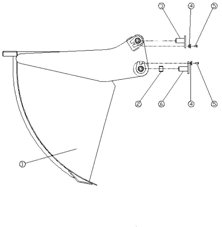
A123322 Apron Model I-180-TS
ITEM |
QTY |
PART NUMBER |
DESCRIPTION |
1 |
1 |
A123322 |
Apron Model I-180-TS |
2 |
2 |
A123299-10 |
Bushing, 2- 2/8” O.D. x 2” I.D. x 1-1/2” long |
|
|
|
with grease groove |
3 |
2 |
A123322-14 |
Pin: 2” x 3-3/4” long, For Apron cyl rod end |
4 |
4 |
A123358 |
Flanged bolt Bushing |
5 |
4 |
AFB-00079 |
Bolt: 5/8” x 1-1/2” |
6 |
2 |
A123322-08 |
Apron Pivot Pin w/grease zerk |
13
 Loading...