

Ashland I-900 User Manual Ver 1-2007

I-900
ver 3-07
S.N. 21615 and up
Ashland Industries Inc.
1115 Rail Drive
P.O. Box 717
Ashland, WI. 54806
Ph: 877-634-4622 Toll Free
Ph: 715-682-4622
Fx: 715-682-9717
www.ashlandind.com

Model I-900 Scraper
HOW TO ORDER PARTS:
IMPORTANT
Parts must be ordered through your local authorized ASHLAND dealer.
Be sure to state MODEL and SERIAL NUMBER of your machine, PART NUMBER, DESCRIPTION
and QUANTITY needed.
Unless this is done, we cannot provide prompt service or assure shipment of the correct parts.
Ashland Industries weldable replacement parts are availabe to rebuild, modify or
update your scraper to current factory specications.
INDEX
Page 3. Safety Guidelines
Page 4. Operators and Maintenance Instructions
Page 5. Illustration - Assembly
Page 6. Illustration and Parts List - Gooseneck Frame Assembly
Page 7. Illustration and Parts List - Apron Assembly
Page 8. Illustration and Parts List - Bowl and Frame Assembly
Page 9. Illustration and Parts List - Push Off Gate Assembly
Page 10. Illustration and Parts List - Pole and Axle Assembly
Page 11. Illustration and Parts List - Wheel Hub and Spindle Assembly
Page 12. Illustration and Parts List - Hydraulic Cylinder, 4” x 16”
Page 13. Illustration and Parts List - Hydraulic Cylinder, 3-1/2” x 10”, Right
Page 14. Illustration and Parts List - Hydraulic Cylinder, 4” x 50”
Page 15-18 Illustration and Parts List - Hydraulic Circuit
Page 19-20 Illustration and Parts List - Hydraulic Manifold Assembly
Page 21. Instructions for Adjusting Hydraulic Manifold Assembly
Page 22. Warranty Statement
2

SAFETY SIGNAL WORDS
Note the use of the signal words DANGER, WARNING and CAUTION with the safety messages. The appropriate signal word for each has been selected using the following guidelines:
DANGER: Indicates an imminently hazardous situation that, if not avoided, will result in
death or serious injury. This signal word is to be limited to the most extreme situa tions typically for machine components which, for functional purposes, cannot be
guarded.
WARNING: Indicates a potentially hazardous situation that, if not avoided, could result
in death or serious injury, and includes hazards that are exposed when guards are
removed. It may also be used to alert against unsafe practices.
CAUTION: Indicates a potentially hazardous situation that, if not avoided, may result in
minor or moderate injury. It may also be used to alert against unsafe practices.
GENERAL SAFETY GUIDELINES
Safety of the operator is one of the main concerns in designing and developing a new piece
of equipment. Designers and manufacturers build in as many safety features as possible.
However, every year many accidents occur which could have been avoided by a few seconds of thought and a more careful approach to handling equipment. You, the operator,
can avoid many accidents by observing the following precautions in this section. To avoid
personal injury, study the following precautions and insist those working with you, or for
you, follow them.
Replace any CAUTION, WARNING, DANGER or instruction safety decal that is not readable
or is missing. Location of such decals is indicated in this booklet.
Do not attempt to operate this equipment under the inuence of drugs or alcohol.
Review the safety instructions with all users annually.
This equipment is dangerous to children and persons unfamiliar with its operation. The
operator should be a responsible adult familiar with farm machinery and trained in this
equipment’s operations. Do not allow persons to operate or assemble this unit un-
til they have read this manual and have developed a thorough understanding of
the safety precautions and of how it works.
To prevent injury or death, use a tractor equipped with a Roll Over Protective System
(ROPS). Do not paint over, remove or deface any safety signs or warning decals on your
equipment. Observe all safety signs and practice the instructions on them.
Never exceed the limits of a piece of machinery. If its ability to do a job, or to do so safely,
is in question - DON’T TRY IT.
3

OPERATORS AND MAINTENANCE INSTRUCTIONS
This scraper is a durable piece of equipment and with proper care will yield many years
of trouble free operation. The scraper requires a power source with TWO 4 way (double
acting) hydraulic control valves.
The scraper should be greased at all points where grease ttings are provided. Connect
hydraulic hoses to the tractor and retract lift cylinders to REMOVE TRANSPORT LOCK
PINS (point A), then extend and retract all cylinders several times to force out any air from
the hydraulic cylinders and lines. Check the oil levels in the tractor hydraulic system and
add to maintain the proper level. Care should be used when adding oil or when disconnecting any oil line to keep all dirt out of the oil as dirt is a major factor in the failure of
hydraulic components.
When the scraper is placed into operation, the operator will have to “feel out” the
amount of depth of cut to obtain maximum loading efciency. This is usually accomplished
by taking a lesser and more uniform cut; however, some soil conditions such as loose sand
may require a “pumping action” obtained by taking successive deep cuts and lifting out of
cut as the tractor begins to lose power or traction.
1. After 10 hours work, all bolts should be checked and tightened if necessary.
2. Every 10 hours all grease ttings should be lubricated.
3. After 50 hours work, all bolts should be rechecked and tightened if necessary.
Check wheel bearings and adjust if necessary.
4. After 300 hours work, clean and repack wheel bearings and replace, if necessary,
cutting edges, worn pins, etc.
4
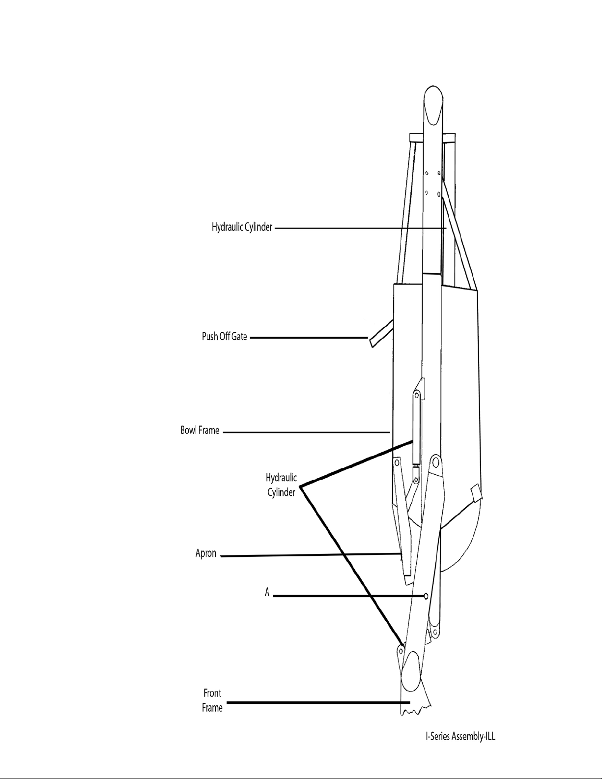
Illustration Assembly
5
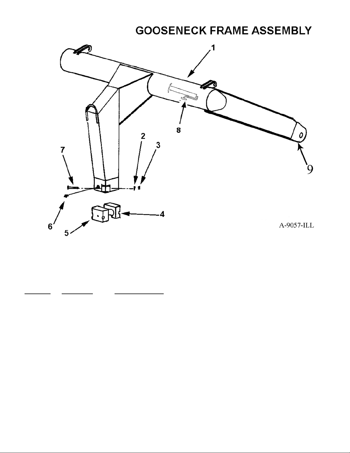
KEY NO. PART NO. DESCRIPTION
1 A9057 Gooseneck Frame
2 8110 Lock washer, 5/8”
3 7530 Nut, 5/8” NC
4 A90004 Cast socket half, rear
5 A90005 Cast socket half, front w/ zerk hole
6 A2206 Grease zerk, long shank
7 AFB-00002 Bolt, 5/8” NC x 4”
8 OPT-00001 Hitch Jack
9 AHF-0028
Fitting Grease 90° 1/8 NPT
6
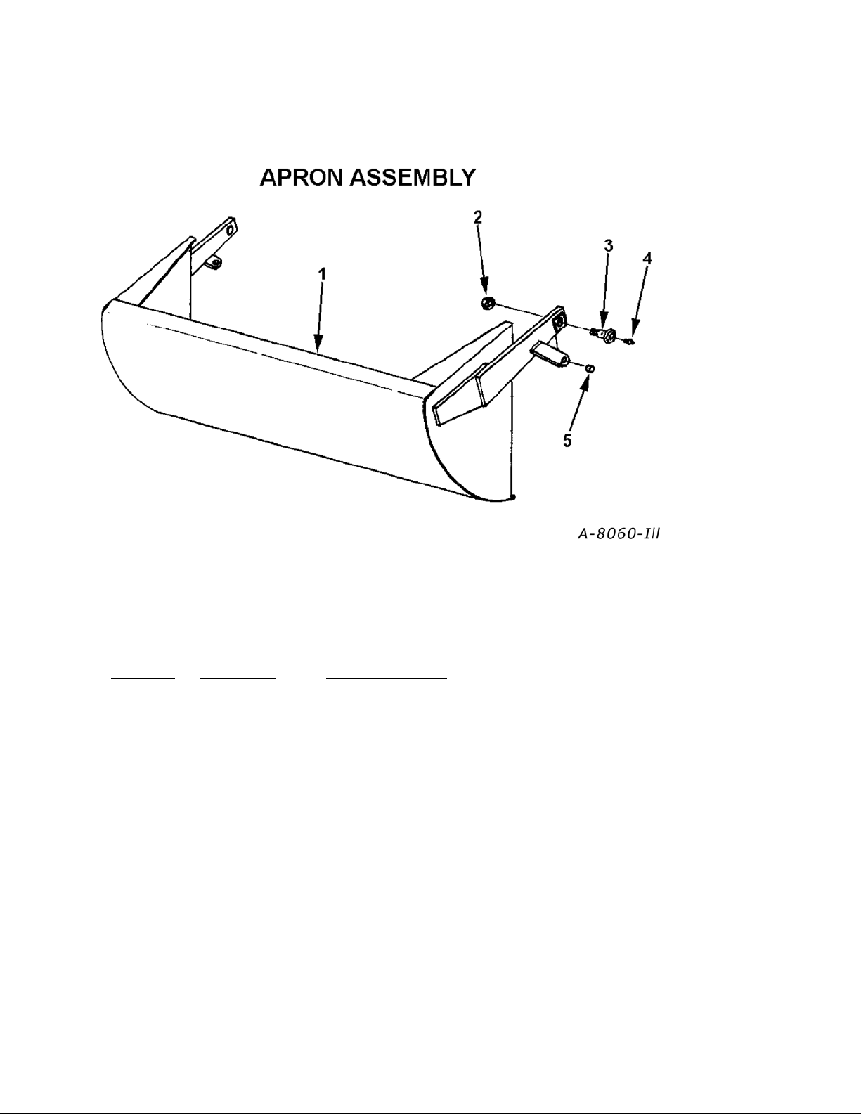
KEY NO. PART NO. DESCRIPTION
1 A8060 Apron
2 AFN-00009 Self locking nut, 1-1/4”
3 A6010 Shoulder pin, 1-5/8” to 1-1/4” with zerk in head
4 14505 Grease tting
5 A10155 Bushing, 1” ID x 1-1/2” OD x 1-1/8” long steel
7
 Loading...