

Ashland I-155TS2 User Manual

EARTHMOVERS
I-155-TS2
PARTS MANUAL
ver 1008
Ashland Industries Inc.
1115 Rail Drive
P.O. Box 717
Ashland, WI. 54806
877-634-4622 Toll Free - phone
715-682-4622 phone
715-682-9717 fax
www.ashlandind.com

I-155 TS2
A
How to Order Parts
HOW TO ORDER PART S:
IMPORTANT
Parts must be orde red through your local au thorized ASH LAND dealer.
Be sur e t o state MODEL and SERIAL NUMBER of your machine, PART NUMBER, D ESCRIPTION and
QUANTITY needed.
Unless this is done, we cannot provide prompt service or assur e shipment of the correct parts.
shland Industr ie s weldable replacement parts are ava ilable to rebuild, modify or upda te your
scrape r to current factory sp eci fica tions .
INDEX
Page 2 Sa fety Guidelines
Page 3 Oper ators an d Maintenance Instru ctions
Page 4 Tran spor t Lock-up Links
Pages 5-6 Swivel Hitch Assembly – Illustration and Parts List
Page 7 Apron Assembl y – Illustrati on and Parts List
Page 8 Front End Assembly – Illustrations and Parts List
Page 9 Bowl and Frame – Illust rat io n an d Par t s List
Page 10 Push Off Gate Assembl y – Ill ustrat ion a nd Part s List
Page 11 Rear Whee l a nd H ub Assembly – Ill us tration an d Pa rts List
Page 12 Apron Cylinder 4” x 13” – Illustration and Parts List
Page 13 Lift Cylinder 5” x 20” – Illustration and Parts List
Page 14 Push Off Cylinder – 5” x 60” – Illustration and Parts List
Page 15 Nitrogen/Hyd. Acc umulator – Illustration and Parts L ist
Page 16 Dec als – Illustrati on and P art s L ist
Page 17 -19 Hydraulic Valve – Identification, Illu stration, Parts Li st and Adjustment
Page 20-22 Service Manual Appendix
Page 23 Troubleshooting
Page 24 Warrantee Statement
Ashland Industries Toll-free:877-634-4622 Fax:715-682-9717
Page #1

I-155 TS2
Safety Guidelines
SAFETY SIGNAL WOR D S
Note the use of the signal words DANG ER, WARNING and CAUTION with t he safety messages. The appropriate signal
wo r d for each has been selected usin g the following guideli nes :
DANGER: Indicates an im m inently haz ar dous si tuation that, if not avo ided, will r es ult in death or serious injury.
This s ignal w or d is to b e limited to the mos t extr em e situations typically fo r machine compon ents which, for fu nc tion al
pu r pos es, cannot be guarded.
WARNING: I ndicates a pot entially haz ar dous s ituation that, if not av oided, c ould result in death or ser ious injury,
and inc ludes hazards th at a r e ex posed when gua rds ar e r em ov ed. It may also be used t o alert against un s afe
practices.
CAUTION:
It may als o be used to aler t again s t unsafe pr ac tices.
Saf ety of the op er ator is one of the main concerns in designing and devel oping a new pie ce o f equipme nt. Desi gners and
manufact urers build in as many saf ety features as possible. However, every year many accidents occur which could have
be en avoided by a few second s of thought a nd a m or e c ar efu l approac h t o handli ng equip ment. You, the ope ra tor, can
avoid many acciden ts by observ ing the follow ing precaut ions in this sec tion . To av oid personal injury, study the followi ng
precaut ions and in sist those working with y ou, or f or yo u, follow t hem.
Re place any CA UTION, WARNI NG, DANGER or ins truct ion safet y dec al th at i s not readab le or is m is s ing. Loc ation of
such de cals is indic ated in this booklet.
Do not attempt to oper ate this equipment under the influence of drugs or alcohol.
Re v iew t he safety ins tructions with al l us er s annual ly .
This equip me nt i s dangerous t o c hildren a nd persons unf a miliar with it s oper at ion. The oper ator should be a responsi ble
adult familiar with farm machinery and trained in this equipment’s operations. Do not al low per so ns to oper a te or
as semble t his unit until th ey have read th is manu al and have develo ped a thorough un derst andin g o f the saf ety
precau t ions and of how it wo rks.
To prevent injury or death, use a tractor equipped with a Roll Over Protective System (ROPS). Do not paint over, remove
or defac e any s afety si gns or war ning decals on y our equipment. Obs er v e all safety si gns and prac tice t he ins truct ions on
them.
Ne v er exceed the limits of a piec e of machinery. If its ability to do a job, or t o do s o safely, is in quest ion - DON’T TRY IT .
I ndicat es a poten tially h az ar dous situation that, if not avoided, ma y r es ult in minor or moder ate i njury.
GENE R AL SAF ETY GUIDELINE S
Ashland Industries Toll-free:877-634-4622 Fax:715-682-9717
Page #2

I-155 TS2
g
g
Operators and Maintenance Instructions
OP ERATORS AND MAINTENANCE INSTRUCTIONS
This scra per is a durable pi ece of e quipment a nd with proper care will yield many year s of trouble
free ope ration. The scraper requires a power source w ith T WO 4 way (double acting) hydraulic
control v alves .
The scraper should be
hoses to the tractor and retract lift cylinders to REMOVE TRANSPORT LOCK PINS, then e xtend
and retract all cylinde r s several times to force out any ai r from the hydr aulic cylinders and lin es.
C hec k th e oi l lev el s in the tra ctor h y dr a u lic syst em an d ad d to m ain tain t h e prop er le vel. Care
should be used whe n addin
is a m a j o r fa cto r in th e fa ilure o f hyd raulic com p on e n t s.
W hen the s c r a p er is plac ed in to op e r at ion, th e op erato r w il l ha ve to “f eel out” the am ou n t of
depth of cut to o btain maximum loa ding effi ciency. This is usua lly acc omplished by taking a les ser
and more uniform cut; however, some soil conditions suc h as lo ose sand may require a “pumping
acti on” obtained by taking successive deep cuts and lifting out of cut as the tractor begins to los e
power or tracti on.
1. Afte r 10 hou rs work , all bo lts sh ould be checked and tightened i f necessar y.
2.
Every 10 hours all grease fi ttings should be lubricated.
reased at all points wh ere greas e fi ttings are provided. Connect hydraulic
oil or when dis conn ecting any oil lin e t o kee p al l d irt out of the oi l as di rt
3.
4. After 300 ho urs work, clean and repack wheel bearings and repl ace, if necessary, cutting
5. Tight en all wheel bolts after first two hours use. Check d ai ly for two wee ks. Keep torqued
6. Maintain tire pres sure at 45 to 50 psi.
Ashland Industries Toll-free:877-634-4622 Fax:715-682-9717
After 50 hours work, a l l bolts should be recheck ed and tight ened if necessa ry. Che ck
wheel bearin gs and adjust if necessary.
edges, worn pin s, et c.
to 750 ft.l b s.
Page #3

I-155 TS2
Transport Locks
Key Number Part Number Description
01 A125006 Pin, Safety Snap Pin
02 A123309-83 Link, Transport Lock, Red
Ashland Industries Toll-free:877-634-4622 Fax:715-682-9717
Page #4
I-155 TS2
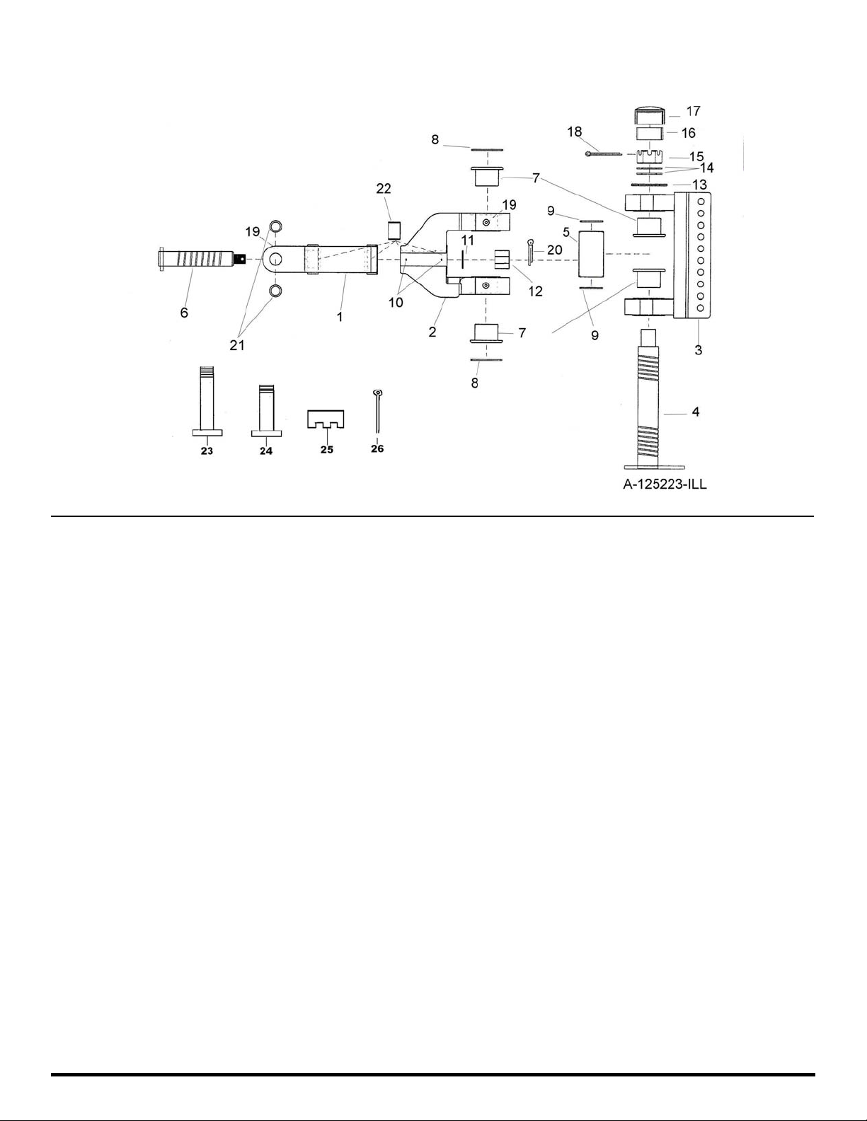
Swivel Hitch Assembly Part Number A125223
Key Number Part Number Description
01 A125223-01 Yoke: A-Frame
02 A125223-02 Swivel
03 A125223-03 Bracket: 10 Hole
04 A125223-04 Pin: Main Vertical
05 A125223-05 Spacer: 6”
06 A125223-06 Pin Horizontal
07 A125223-07 Bushing
08 A125223-08 Seal: O-ring
09 A125223-09 Seal: O-ring
10 AFH-00028 Grease Fitting: 90°
11 A125223-11 Washer- 1-1/2” For Horizontal Pin
12 A125223-12 Nut: Slotted 1-1/2” NC
13 A125223-13 Spacer: 6”
14 A125223-14 Washer: 2 1/2”
15 A125223-15 Nut: Slotted 2-1/2” NC
16 A125223-16 Sleeve: 2” Rubber
17 A125223-17 Cap: For Vertical Pin
18 A125223-18 Pin: Cotter 3/8 x 5”
19 14505 Grease Fitting Straight
20 8613 Cotter Pin: 5/16 x 2-1/2”
21 A125056-24 Bushing
22 A125056-27 Bushing
23 A123299-07 Pin: Two Ear Draw Bar to Hitch
24 A123299-08 Pin: Four Ear Drawbar to Hitch
25 AFN-00014 1 1/2" Slotted Nut
26 AFP-00001 1/4" X 3" Cotter Pin
Ashland Industries Toll-free:877-634-4622 Fax:715-682-9717
Page #5
I-155 TS2
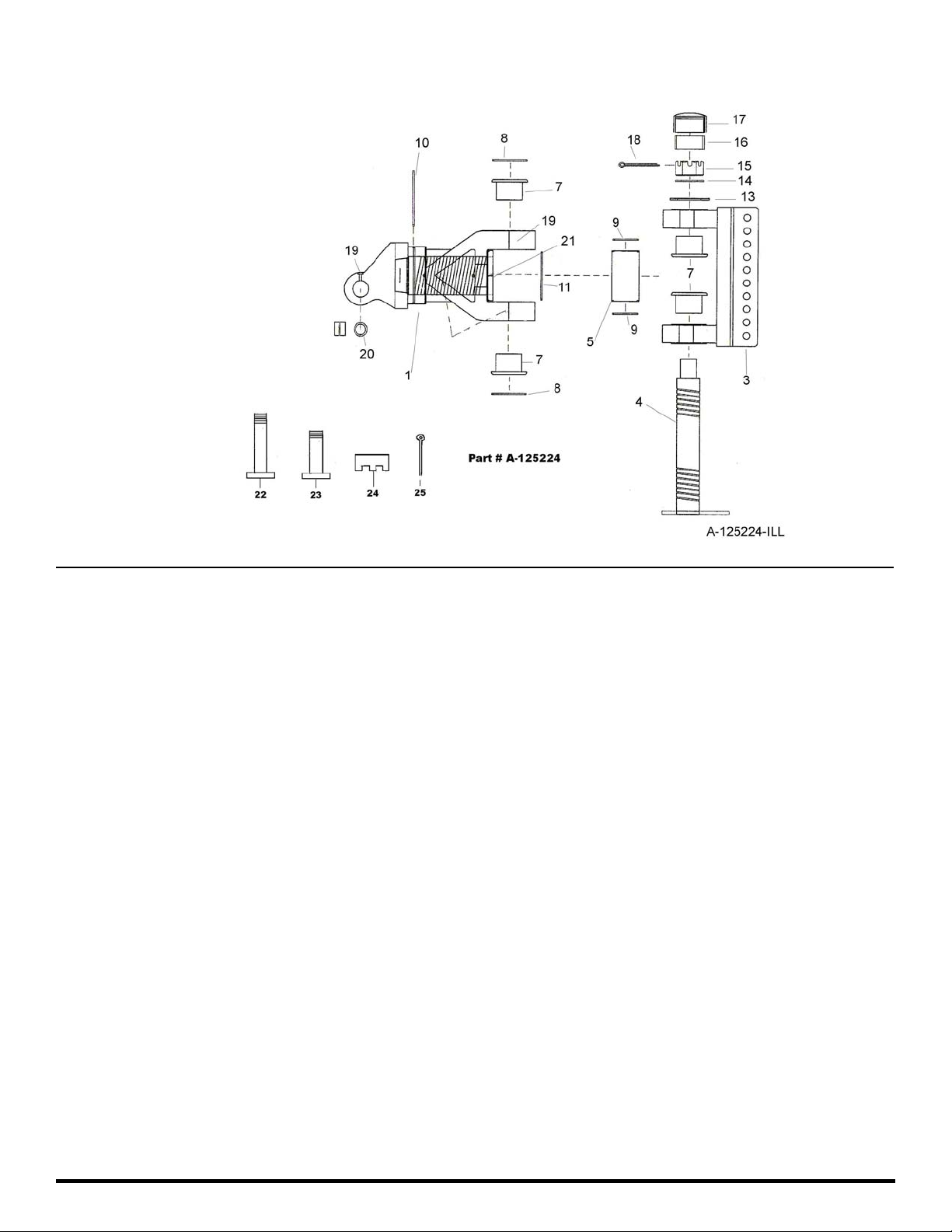
Icon Swivel Hitch (Optional) Part Number A125224
Key Number Part Number Description
01 A125224-01 Yoke: A-Frame swivel
03 A125224-03 Bracket: 10 Hole
04 A125224-04 Pin: Main Vertical
05 A125224-05 Spacer: 6”
07 A125224-07 Bushing
08 A125224-08 Seal: O-ring
09 A125224-09 Seal: O-ring
10 A125224-10 O-ring
13 A125224-13 Spacer: 6”
14 A125224-14 Washer: 2 1/2”
15 A125224-15 Nut: Slotted 2-1/2” NC
16 A125224-16 Sleeve: 2” Rubber
17 A125224-17 Cap: For Vertical Pin
18 A125224-18 Pin: Cotter 3/8 x 5”
19 14505 Grease Fitting Straight
20 A125056-24 Bushing
21 AHF-00027 Zerk 45°
22 A123299-07 Pin: Two Ear Drawbar to Hitch
23 A123299-08 Pin: Four Ear Drawbar to Hitch
24 AFN-00014 1 1/2" Slotted Nut
25 AFP-00001 1/4" X 3" Cotter Pin
Ashland Industries Toll-free:877-634-4622 Fax:715-682-9717
Page #6
I-155 TS2
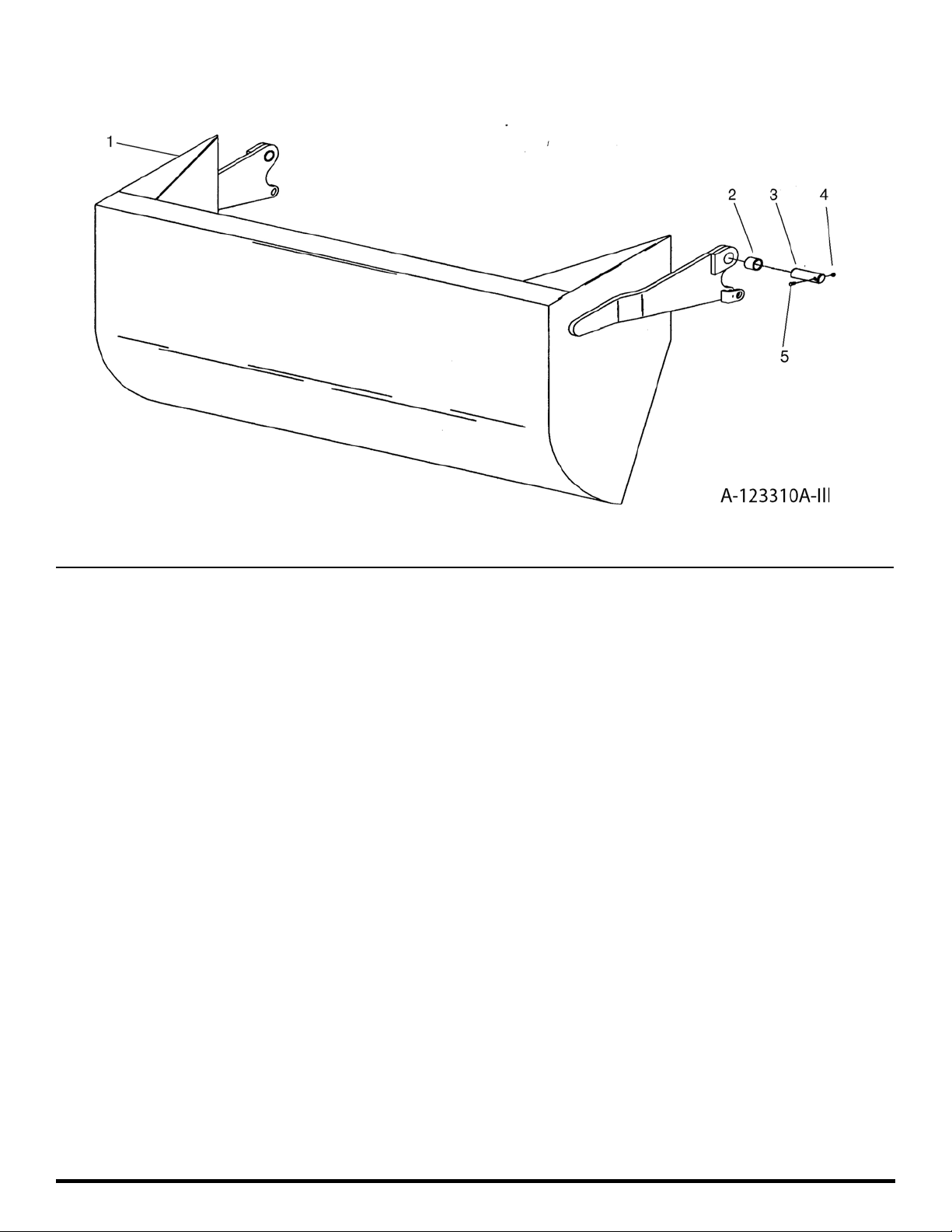
Apron Assembly
Key Number Part Number Description
01 A123310A Apron Model I-155 TS
02 A16027 Bushing: 2” OD x 1-1/2” ID x 2” Long
03 A123337 Pin: 1-1/2” x 5-3/8”
04 7450 Nut: 3/8” NC
05 AFB-00049 Bolt: 3/8” NC x 3”
Ashland Industries Toll-free:877-634-4622 Fax:715-682-9717
Page #7
 Loading...