

Ashland 500 User Manual

Models 450 & 500
PARTS MANUAL
Ashland Industries Inc.
1115 Rail Drive
P.O. Box 717
Ashland, WI. 54806
Ph: 877-634-4622
Ph: 715-682-4622
Fx: 715-682-9717
www.ashlandind.com
Toll Free
Version 4-04

Model 450 & 500 Scrapers
HOW TO ORDER PARTS:
IMPORTANT
Parts must be ordered through your local authorized ASHLAND dealer.
Be sure to state MODEL and SERIAL NUMBER of your machine, PART NUMBER, DESCRIPTION
and QUANTITY needed.
Unless this is done, we cannot provide prompt service or assure shipment of the correct parts.
Ashland Industries weldable replacement parts are availabe to rebuild, modify or
update your scraper to current factory specifications.
INDEX
Page 3. Operator and Maintenance Instructions
Page 4. Safety Guidelines
Page 5-6. Assembly Instructions
Page 7. Frame Assembly
Page 8. Pole, Axle, Hub & Wheel
Page 9. Actuating Assembly
Page 10. Bucket Assembly
Page 11. Rear Frame Assembly
Page 12. Wheel, Hub and Spindle Assembly
Page 13. Single Lock Line Valve
Page 14. Sequence Valve, Line Check Valve
Page 15. Hydraulic Cylinder (Right, 4” x 16”)
Page 16. Hydraulic Cylinder (Left, 4” x 16”)
Page 17. Hydraulic Cylinder (4” x 8”)
Page 18. Plumbing Assembly
Page 19. PMC-5600D Series
Page 20. How to Operate the W7B-20DC Rim
Page 21. Warranty Statement
2

OPERATORS AND MAINTENANCE INSTRUCTIONS
This scraper is a durable piece of equipment and with proper care will yield many years of
trouble free operation. The scraper requires a power source with one 4-way (double
acting) hydraulic control valve.
After scraper has been assembled, it should be greased at all points where grease fittings
are provided. Connect hydraulic hoses to tractor and operate the scraper to maximum
raise and drop several times to force any air from the hydraulic lines and cylinders. Check
the oil level in the tractor hydraulic system and add to maintain the proper level.
When the scraper is placed into operation, the operator will have to ”feel out” the amount
of depth of cut to obtain maximum loading efficiency. This is usually accomplished by
taking a lesser and more uniform cut. However, some soil conditions such as loose sand
may require a “pumping action” obtained by taking successive deep cuts and lifting out of
cut as the tractor begins to lose power or traction.
1. After 10 hours work, all bolts should be checked and tightened if necessary.
2. Every 10 hours all grease fittings should be lubricated.
3. After 50 hours work, all bolts should be rechecked and tightened if necessary. Check
wheel bearings and adjust if necessary.
4. After 300 hours work, clean and repack wheel bearings and replace, if necessary, cutting edges, worn pins, etc.
SPREAD CONTROL ON MODEL 450 AND 500 SCRAPERS
The hydraulic cylinder on the rear section of the main frame controls the distance the
cutting edge is from the ground after the bucket is in dump position. When the bucket first
reaches dump position, the cutting edge is at the minimum spreading depth (approx. 2”)
and as additional depth of spread is desired, the same hydraulic control valve on the tractor
is actuated and the cutting edge raises allowing for the increased depth of spread.
This is accomplished when the flow of hydraulic oil is automatically diverted from one of
the hydraulic cylinders on the side of the scraper to the hydraulic cylinder at the rear. The
rear cylinder lifts the entire main frame and bucket assembly upward, allowing for the
increased distance between the cutting edge and the ground.
ASHLAND INDUSTRIES, INC.
3

SAFETY SIGNAL WORDS
Note the use of the signal words DANGER, WARNING and CAUTION with the safety messages. The appropriate signal word for each has been selected using the following guidelines:
DANGER: Indicates an imminently hazardous situation that, if not avoided, will result in
death or serious injury. This signal word is to be limited to the most extreme situations typically for machine components which, for functional purposes, cannot be
guarded.
WARNING: Indicates a potentially hazardous situation that, if not avoided, could result in
death or serious injury, and includes hazards that are exposed when guards are
removed. It may also be used to alert against unsafe practices.
CAUTION: Indicates a potentially hazardous situation that, if not avoided, may result in
minor or moderate injury. It may also be used to alert against unsafe practices.
GENERAL SAFETY GUIDELINES
Safety of the operator is one of the main concerns in designing and developing a new piece
of equipment. Designers and manufacturers build in as many safety features as possible.
However, every year many accidents occur which could have been avoided by a few seconds of thought and a more careful approach to handling equipment. You, the operator,
can avoid many accidents by observing the following precautions in this section. To avoid
personal injury, study the following precautions and insist those working with you, or for
you, follow them.
Replace any CAUTION, WARNING, DANGER or instruction safety decal that is not readable
or is missing. Location of such decals is indicated in this booklet.
Do not attempt to operate this equipment under the influence of drugs or alcohol.
Review the safety instructions with all users annually.
This equipment is dangerous to children and persons unfamiliar with its operation. The
operator should be a responsible adult familiar with farm machinery and trained in this
equipment’s operations. Do not allow persons to operate or assemble this unit
until they have read this manual and have developed a thorough understanding
of the safety precautions and of how it works.
To prevent injury or death, use a tractor equipped with a Roll Over Protective System
(ROPS). Do not paint over, remove or deface any safety signs or warning decals on your
equipment. Observe all safety signs and practice the instructions on them.
Never exceed the limits of a piece of machinery. If its ability to do a job, or to do so safely,
is in question - DON’T TRY IT.
4

MODELS 450 & 500 SCRAPER ASSEMBLY INSTRUCTIONS
1. A suitable hoist or lift should be available for assembly.
2. Pack wheel bearing with grease and install hubs to rear spindles and front axle assembly. Be
sure to follow the bearing numbers as shown in the parts listing as the front hubs require different
bearings than the rear.
3. Raise actuating frame over bucket and lower into place so that the holes in the arms of the
actuating frame aligns with the rear hole on each side of the bucket. Insert 1 ¼ ” x 2-9/16” pin
(with tab type head) from the inside of the bucket. Secure with 5/8” x 1 ½ ” NF bolt through
bucket side with locking nut to the outside.
4. Connect actuating arm bars to the front holes in the bucket. In doing so, be sure that the cast
roller on the opposite end of the actuating arm is in the up position and facing inward. Insert 1 ¼
x 2-9/16 ” pin (with tab type head) from the inside on the bucket. Secure with 5/8” x 1 ½ ” NF
bolt through the bucket side with lockwasher and nut to the outside.
5. Connect a short chain from the cutting edge to the cross pipe of the actuating frame, then
raise this bucket and actuating assembly over the main frame and lower into place so that the
front of the actuating frame can be connected to the 1 ½ ” ID bearing on the side of the main
frame. Secure with 1 ½ ” x 5-5/8” pins on each side. Lock these pins in place by turning the pin
until the hole in the head aligns with threaded hole in the actuating frame, then secure with ½” x 1”
NC capscrew and lockwasher.
6. Lift front end of actuating arms and connect to the brackets on the front frame cross member
using the 1 ¼ ” x 4-1/8” pins. Secure with ¼” x 2” cotter pin.
7. Raise the apron assembly over the scraper and lower into position so that the holes in the arms
of the apron align with the holes in the bucket sides. Insert the 1 ¼ ” to 1” shoulder pin through
the apron arms and into the bucket. Install lock nut inside the bucket and tighten securely.
8. Installing the hydraulic cylinders:
A. Install the cylinder with three hose ports on the left side of the scraper with the rod end to
the actuating frame and the grease hole in the rod end bushing facing up. Use 1-1/8” x 3 ¼”
pin at the base of the cylinder. Secure with 3/16” x 1 ½” cotter pins. Use 1-1/8” x 6” pin at
the rod end of the cylinder. Secure with ½” x 1” NC capscrew and lockwasher.
B. Install 3/8” NPT 90° swivel adapter in all three ports of the cylinder. Tighten so that the
swivel will be facing toward the rear. The extreme forward swivel will have to be turned slightly
to the outside so that the hose will clear the swivel in the center port.
C. Connect a 3/8” x 18” hose from the forward pipe line on the frame cross-member to the
base (rear) port of the cylinder.
D. Connect a 3/8” x 36” hose from the pipe line on the frame cross-member tot he center
port of the cylinder.-
E. Connect a 3/8” x 36” hose from the center pipe line on the frame cross-member to the
extreme forward port of the cylinder.
5

F. Install the cylinder with the two hose ports on the right side of the scraper with the rod end
to the actuating frame, and the grease hole in the rod end bushing facing up. Use the same
size pins as the cylinder on the left side.
G. Install 3/8” NPT 90° swivel adapters in both ports of the cylinder. Tighten so that the
swivel will be facing toward the rear.
H. Connect a 3/8” x 18” hose from the forward pipe line on the frame cross-member to the
base (rear) port of the cylinder (same as left cylinder).
I. Connect a ½” x 36” hose from the remaining pipe line on the frame cross-member to the
forward port of the cylinder.
J. Install the 4” x 8” hydraulic cylinder on the rear of the scraper with the rod end connected
to the rear frame section with the grease hole facing up. Insert the 1-1/8” x 3-1/8” square
head pin at the base of the cylinder. Secure with 3/16” x 1 ½” cotter pin. Use 1-1/8” x 3 ½”
square head pin at the rod end of the cylinder and secure with a 3/16” x 1 ½” cotter pin.
K. Install 3/8” NPT male x ½” NPT female 90° swivel adapters in the two ports of the rear
cylinder. Tighten so the swivels face toward each other and somewhat to the left of the
scraper.
L. Install one ½” x 24” hose form the lower elbow of the single line lock valve to the base port
of the cylinder. Install the remaining ½” x 24” hose form the upper elbow of the lock valve to
the rod end port of the cylinder.
9. Raise the rear of the frame and install wheels to hubs. Also install wheels to front axle assembly.
10. Raise front of frame and remove the two 5/8” x 4” bolts which hold the cast socket halves
inside the gooseneck. Remove the cast socket halves.
11. Roll the pole and axle assembly directly under the gooseneck, place the cast socket halves
around the ball socket on the axle. Lower the frame into place so that the socket halves seat into
the gooseneck. (If necessary, clamp halves together with C-clamp while inserting into gooseneck).
Replace 5/8” x 4” bolts and tighten securely. Install long shank grease fitting into the hole in the
back side of gooseneck.
12. Install all the grease fittings and grease liberally.
13. If available, place assembled scraper on level floor or pavement and measure the distance
from the cutting edge to floor, on both left and right sides, and then adjust axle spindle to obtain
equal distance on both sides.
ASHLAND INDUSTRIES, INC.
6
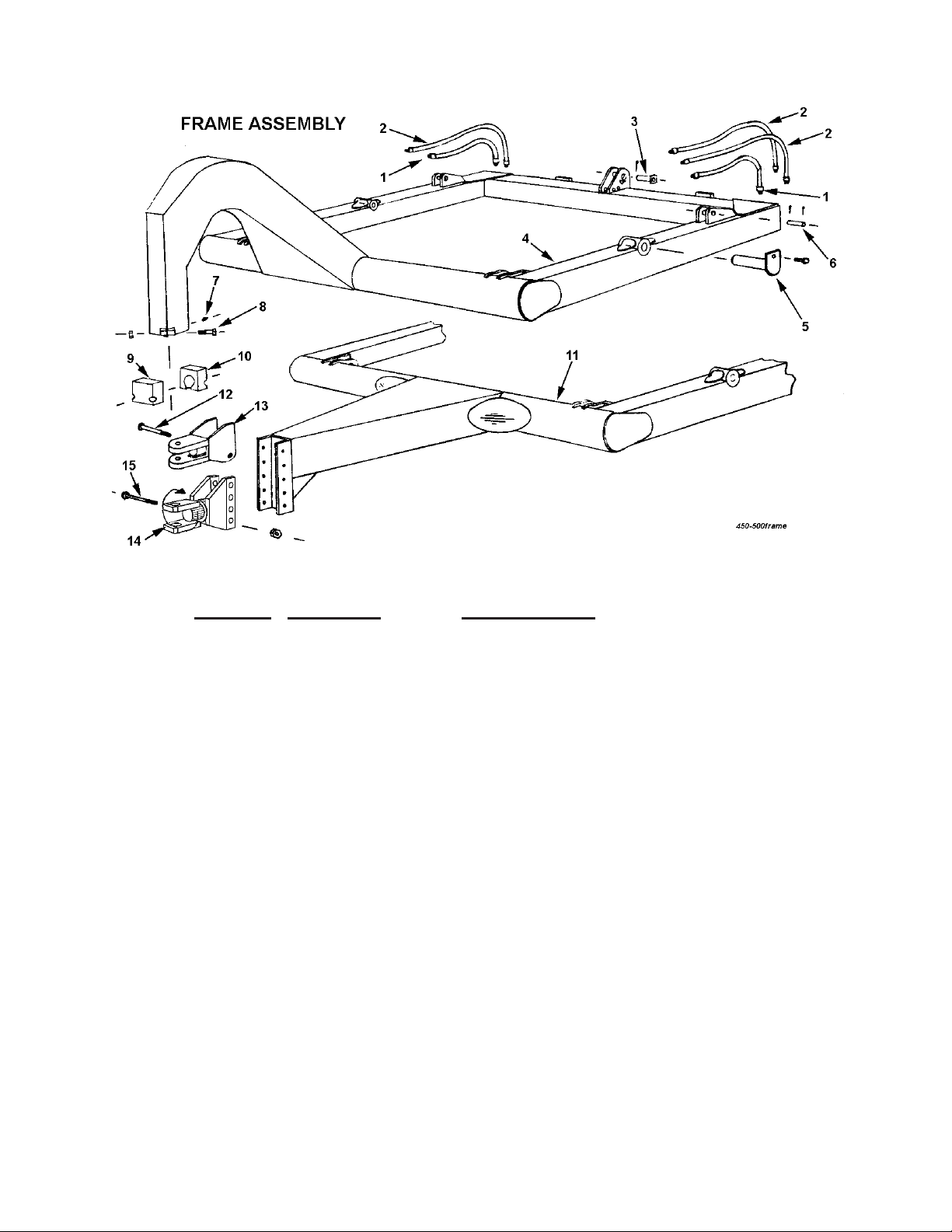
KEY NO. PART NO. DESCRIPTION
1 A450H01 Hydraulic hose, 3/8" x 18" single braid
2 A450H02 Hydraulic hose, 3/8" x 36" single braid
A22H03 Swivel adapter, 3/8" 90°
3 A45001 Pin, 1-1/8" x 3-1/8" w/ sq. head
Cotter pin, 3/16" x 1-1/2"
4 A45002 Frame, four wheel, Model D
5 A2502 Pin, 1-1/2" x 5-5/8" w/ tab head
6 A45003 Pin, 1-1/8" x 3-1/4", cotter both ends
Cotter pin, 3/16" x 1-1/2"
7 A2206 Grease fiting, 1/8" NPT strt. long shank
8 Bolt, 5/8" x 4" NC, w/ nut & LW
9 A40004 Cast socket half, front
10 A40005 Cast socket half, rear w/ grease hole
11 A45004 Frame, two wheel, Model S
12 Bolt, 3/4" x 6" NC w/ nut & LW
13 A4523 Hitch
14 A5004 Swivel hitch
15 Bolt, 1" x 6-1/2" NC w/ nut & LW
7
 Loading...