

Asaklitt 31-8542 User Manual [de]

English
Svenska
Norsk
Suomi Deutsch
20″ Bicycle
Cykel 20 ″
Sykkel 20 ″
Polkupyörä 20 ″
Fahrrad 20 ″
Ver. 20150422
Art.no.
31-8542

English
Art.no 31-8542
Please read theentire instruction manual before using theproduct and then save it for future reference.
We reserve theright for any errors in text or images and any necessary changes made to
technical data. If you have any questions concerning technical problems please contact our
Customer Services.
Contents
1. Safety .........................................................................................................3
2. Product description ..........................................................................4
3. Assembly ............................................................................................... 6
4. Adjusting .................................................................................................7
4.1 Checking/adjusting handlebar height and angle ...................................................7
4.2 Checking/adjusting saddle height and angle ........................................................ 8
5 Checking/adjusting the brakes ................................................. 8
5.1 Front and rear rim brakes .................................................................................................. 8
5.2 Coaster brake ............................................................................................................................ 9
5.3 Checking for rim wear ......................................................................................................... 9
6. Checking/adjusting the gears ................................................... 9
7. Checking/adjusting chain tension ..........................................10
20″ Bicycle
8. Attaching/removing the wheels ...........................................10
8.1 Wheel alignment ....................................................................................................................... 11
9. Care and maintenance ..................................................................11
9.1 Winter storage ........................................................................................................................... 11
10. Disposal .................................................................................................11
11. Specifications ..................................................................................... 12
2

1. Safety
• This bicycle is designed to be ridden on normal roads and not for terrain or competitive use.
Any form of use other than that described in this instruction manual can lead to aserious risk
for personal injury or damage to thebicycle itself.
• Preparations before use: Setting thecorrect saddle and handlebar height. Become familiar
with how thebrakes operate and identify which brake handle operates thefront brake
and which operates therear. This bicycle is even equipped with acoaster brake which is
activated when either of thepedals are pushed in abackwards direction. Make it ahabit of
testing thebrakes regularly. Test thedifferent braking systems in anappropriate area before
embarking on aride. Select anarea free of traffic or other road hinders. Never brake hard
using thecoaster brake in slippery conditions, e.g. on gravel, ice, snow or wet tarmac. For
steep hills several braking methods should be combined, otherwise using thecoaster brake
alone may cause it to overheat.
• Make sure that theseat and handlebar post are set within their recommended limits.
Theposts may not be extended outside or fall short of these recommended limits.
- A) Thehandlebar post has amax extension marking: MIN INSERTION, this marking
indicates that thehandlebar post is at its maximum safe extension point, and shows
theminimum portion that must be inserted into thebicycle’s steering column for safe
operation.
- B) Theseat post has two markings: ↑ MINIMUM INSERT ↑ shows theposition at which
theseat post is at its maximum extension point and ↓ MAXIMUM ↓ theminimum portion
that must be slotted into theframe.
• Recommendations for safe bicycle use – Use abicycle helmet, check brakes regularly and
examine them for wear. Check that all brake components are securely fastened. Check tyres,
wheels and handlebars for wear and performance.
• Remember that braking distance is substantially increased on ice, snow and wet tarmac.
Make sure before every use that thecycle’s quick releases for thehandlebars, handlebar post
and seat post are securely locked along with testing that thehandlebar assembly and frame
lock levers work properly.
• Max bicycle load: Max total weight 119 kg (bicycle + rider+ packing).
• Max bike rack load: 15 kg.
• Max rider weight: 90 kg.
• Remember that rules and regulations for bicycles will differ from country to country. This may
include regulation regarding front, rear and side reflectors along with front and rear lights.
Familiarise yourself with therules and regulations that apply in your country.
• Tighten all nuts, bolts and screws but do not overtighten. (See section 2. Product description).
• Adjust thebicycle so that it fits you. There are quick releases for thehandlebars, handlebar
post and seat post, which makes adjustments easy.
• Always conduct asafety check before riding.
• Always use aproperly adjusted and fitted helmet.
• Always keep both hands on thehandlebars.
• Always ride in thesame direction as traffic flow. Never ride against traffic.
• Always follow theHighway Code.
• Wear clothing that makes you visible to your fellow road users.
• Thebicycle must be equipped with wheel reflectors, both front and back and pedal
reflectors. Make sure that all reflectors are clean and visible.
• When riding in darkness make sure that you have properly functioning lights, both front and rear.
• Warning: Always brake using therear brakes first before attempting to use thefront brakes.
This especially applies if road surfaces are slippery.
English
3
• Never use loose fitting clothing or similar apparel that can get caught in thebicycle’s chain
English
or wheels.
• Show consideration when riding in traffic. Don’t ride close to pedestrians, horse riders or
thedisabled.
Warning: This bicycle is not designed to be used with bicycle child seats or similar.
Warning: As with all mechanical components, thebicycle is subjected to wear and high stresses.
Different materials and components may react to wear or stress fatigue in different ways. If thedesign
life of acomponent has been exceeded, it may suddenly fail possibly causing injuries to therider.
Any form of crack, scratches or change of colouring in highly stressed areas indicate that thelife
of thecomponent has been reached and it should be replaced.
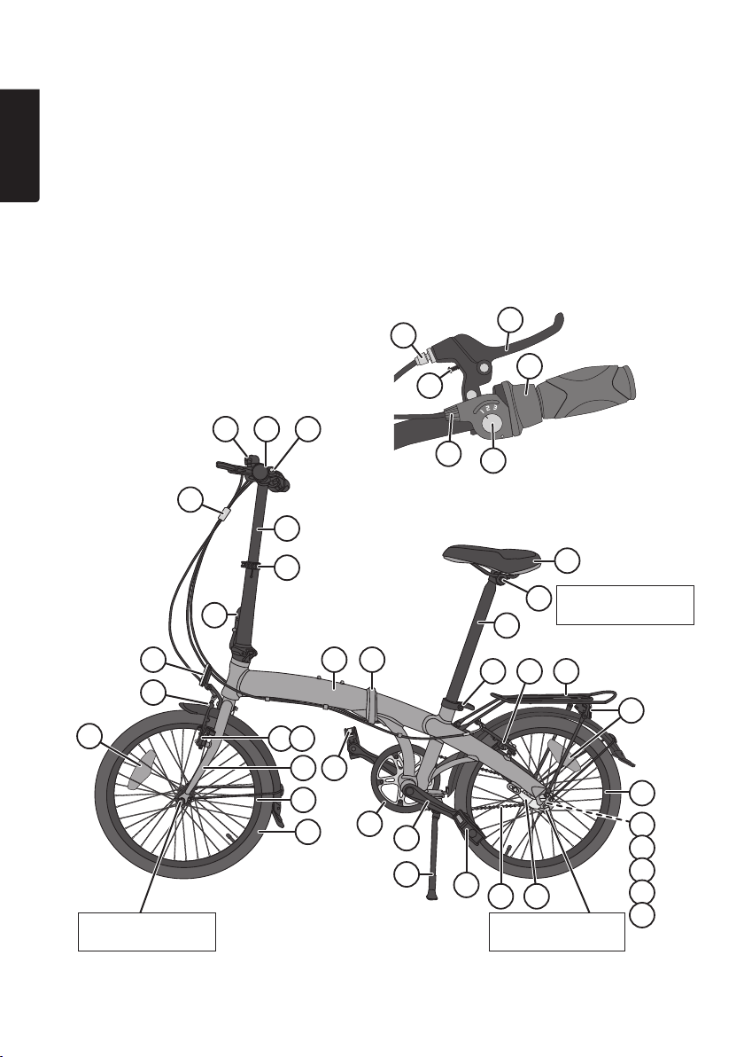
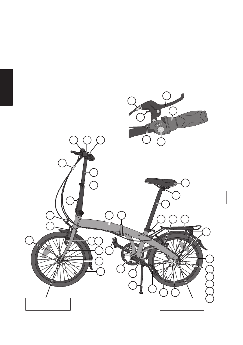
2. Product description
8
7
12 9
5
10
11
6
3
4
14
15
14
Tightening front
wheel 30–35 Nm
13
12
16 17
18 14
19
20
21 22
26
4
23
27
28
31 33
24
25 36
Tightening rear
wheel 35–40 Nm
30
32
29
Tightening
saddle10 Nm
14
34
35
37
38
39
40

1. Handlebar
2. Bicycle bell
3. Gear shifter
4. Gear indicator
5. Gear shifter wire adjustment barrel
6. Brake lever (one on each side)
7. Brake lever adjustment screw
8. Brake wire adjustment barrel
9. Handlebar quick release
10. Wires (3 x)
11. Handlebar post
12. Handlebar post quick release
13. Handlebar assembly lock lever with catch
14. Reflectors (front, rear, wheels and pedals)
15. Front rim brakes
16. Spring tension adjustment screw
17. Brake pads
18. Front fork
19. Front wheel
20. Tyre
21. Frame
22. Bicycle frame lock lever with catch
23. Crankset
24. Pedal
25. Bicycle Chain
26. Chain guard
27. Kickstand
28. Seat post
29. Saddle
30. Saddle clamp bolt
31. Seat post quick release
32. Rear rim brakes
33. Bike rack
34. Rear wheel
35. Rear coaster brake hub
36. Rear coaster brake arm
37. Bellcrank
38. Bellcrank locking screw
39. Bellcrank adjustment barrel
40. Gear adjustment window
English
5
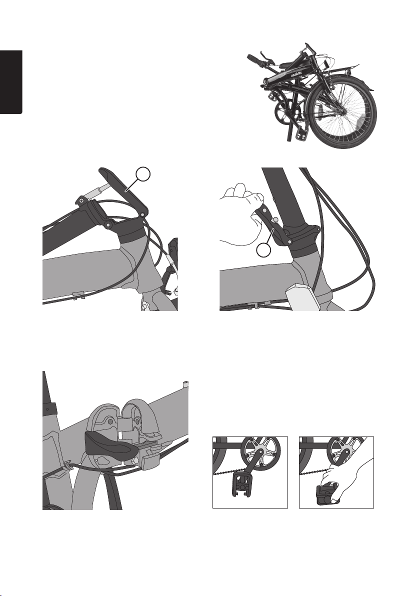
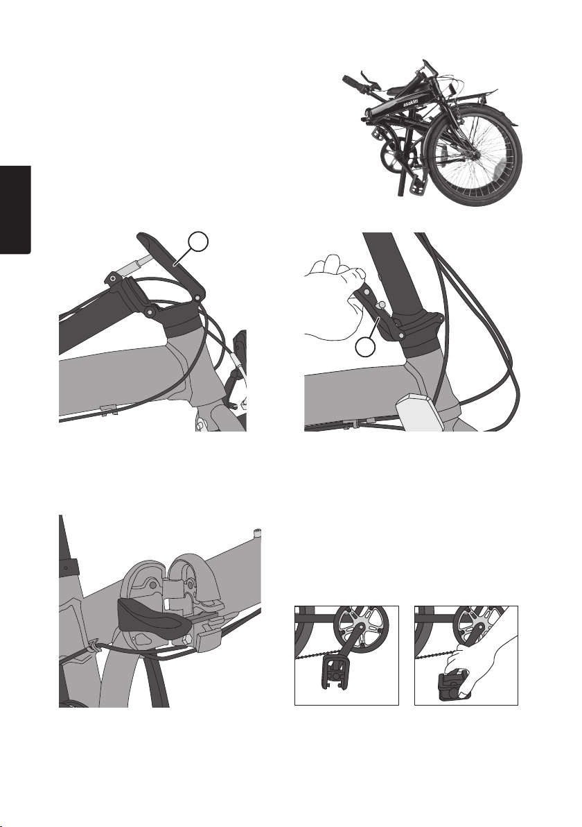
3. Assembly
English
Thebicycle comes fully assembled but in collapsed form.
Unfolding thebike:
13
13
Extend thehandlebar assembly. Press thelock lever (13) upwards towards
Unfold theframe. Grip thepedals and unfold them.
thehandlebar post. Make sure thelock
lever’s catch has engaged into its locked
position. Check that thecatch holds thelock
lever in position so the lever can’t be moved
unless the catch is pressed in.
6
Press thelock lever (22) forwards to lock theframe.
Make sure thelock lever’s catch has engaged into
its locked position. Check that thecatch holds
thelock lever in position so the lever can’t be
moved unless the catch is pressed in.
22
4. Adjusting
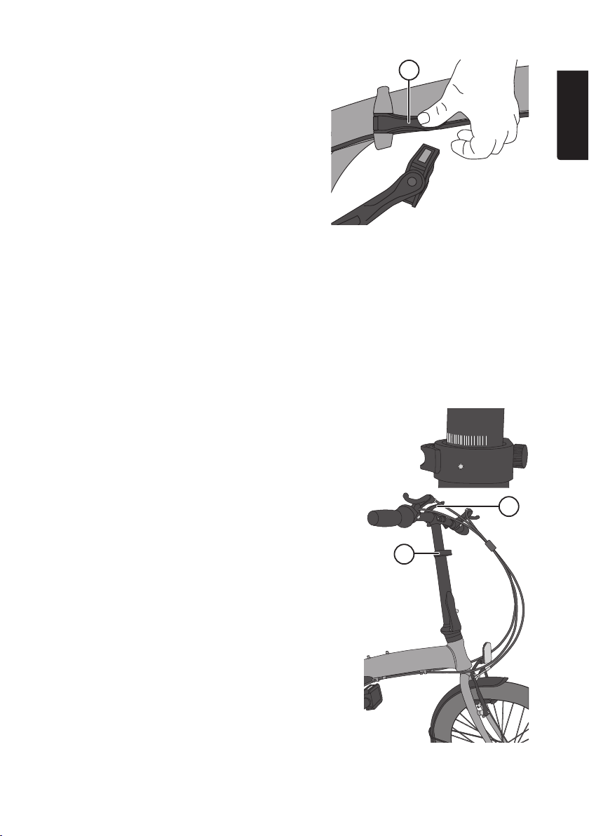
4.1 Checking/adjusting handlebar height and angle
Adjust thehandlebar height and angle to fit you. Pull thehandlebar and seat post up to alevel
that feels right for you. Sit on thesaddle, check for acomfortable height and ensure that your feet
can touch theground on your tiptoes.
Warning: Thehandlebars and handlebar post quick release must not be adjusted while riding.
All adjustments must be made while thebicycle is standing still.
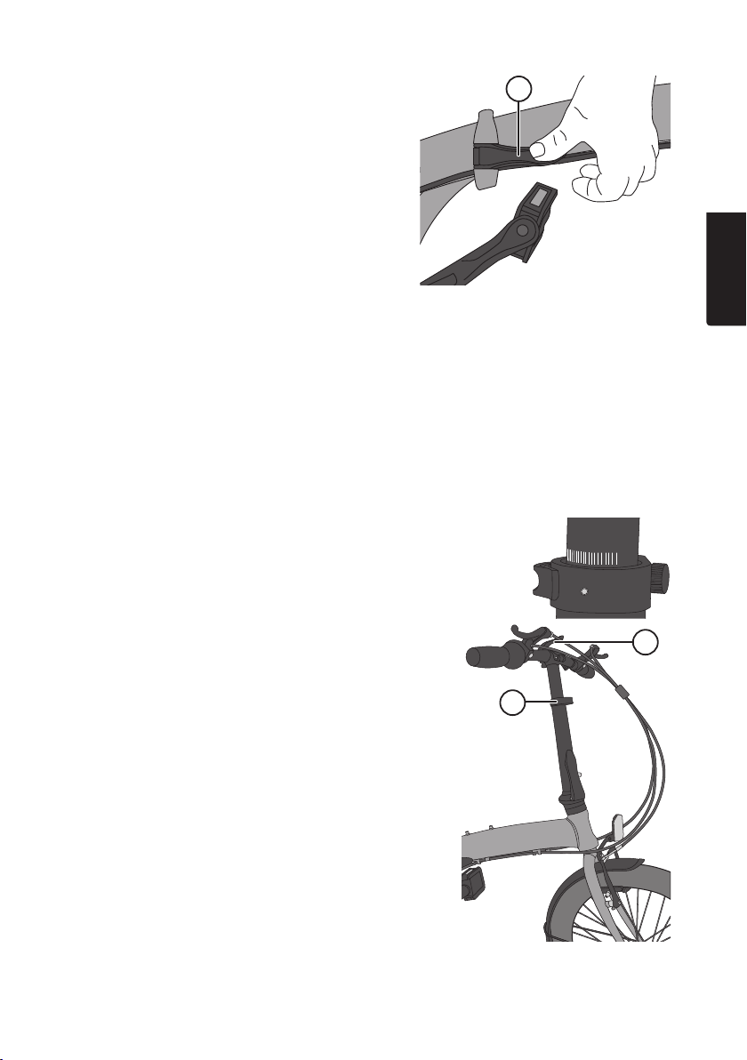
Thehandlebar post (11) has aquick release (12) for quick and easy handlebar height adjustment.
There is also ahandlebar quick release (9) for adjusting thehandlebar angle.
Thehandlebar post has animportant max extension
marking that should be observed: MIN INSERTION,
this marking indicates that thehandlebar post is at its
maximum safe extension point, and shows theminimum
portion that must be inserted into thebicycle’s steering
column for safe operation. Note: TheIIIIIIIIIIIIIIIIIII markings
on theseat post should be clearly visible above theseat
post frame.
9
English
Thehandlebar height should be adjusted so that therider
is in acomfortable and commanding position while
riding. Adjust thehandlebar’s steering angle as needed.
Open thequick release (9) and adjust. Make sure that all
steering components are in proper working order after
adjustment.
Remember to lock all quick-releases before riding!
7
12
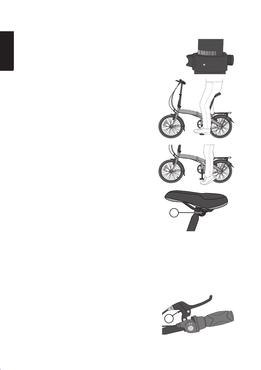
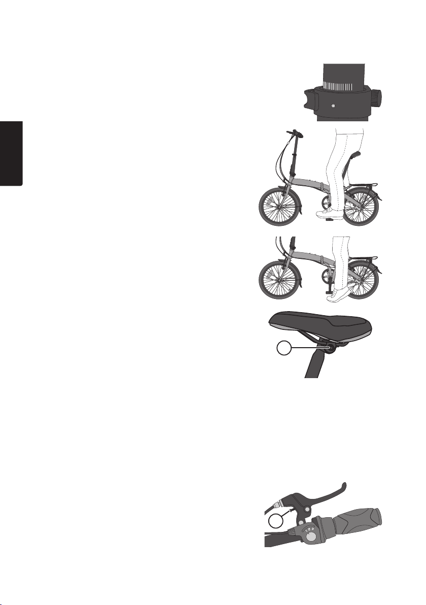
4.2 Checking/adjusting saddle height and angle
English
Loosen theseat post quick-release (30) to adjust.
Note: Theseat post has two markings:
↑MINIMUMINSERT↑ shows theposition at which
theseat post is at its maximum extension point and
↓ MAXIMUM↓ theminimum portion that must be slotted
into theframe. Note: TheIIIIIIIIIIIIIIIIIII markings on
theseat post should be clearly visible above theseat
post frame.
Thesaddle height should be adjusted so that your foot,
with your leg almost completely extended, can be placed
flat onto thepedal at thebottom of thepedal stroke. You
should also be able to touch theground with your tiptoes
if needed.
Thesaddle (29) should be positioned completely
horizontal or tilted slightly backwards. Finding
acomfortable saddle angle is dependent on your
personal tastes. It may require along bike ride for you to
find aposition that is most comfortable for you.
Adjust thesaddle angle by loosening thesaddle clamp
bolt (30). Adjust theangle by tilting thesaddle forwards
or backwards.
Remember to re-tighten all screws and nuts before riding!
Warning: Always make sure that thelock levers, both for
theframe (22) and handlebar assembly (13) are securely
locked and that their catches hold and operate properly!
30
5 Checking/adjusting the brakes
5.1 Front and rear rim brakes
Check that both rims are whole and free from grease or oil.
Regular brake checking procedure: Pull thebrake handles and make sure that thebrake lines
are whole, that both brake pads make contact with therims simultaneously and that thebrake
handles cannot be pulled so far that they bottom out onto thehandlebars.
Adjust therim brakes as necessary.
• Adjust thebrake pads (17) to ensure that they are
aligned with therims and do not come into contact
with thetyres during braking.
• Thedistance between thebrake pads and therims
should be about 1–2 mm. Adjust this distance
using thebrake wire adjustment barrel (8) at
thehandlebars.
8
8
• Adjust thebrake position using thespring tension
screws (16) so that each brake pad makes contact
with therims simultaneously.
• Change brake pads when necessary using thesame
type of brake pads as thebike was originally
equipped with. Brake pads should be positioned
(toe-in) angled inwards with thebrake pad’s leading
edges approximately 1 mm from therim. Thebrake
pads have spherical washers for adjustment purposes.
16
5.2 Coaster brake
Thecoaster brake cannot be adjusted. Warning: Make sure that thebrake arm (36) is securely
fastened, otherwise it will not function properly. This can cause therear wheel to lock and
increase therisk for personal injury.
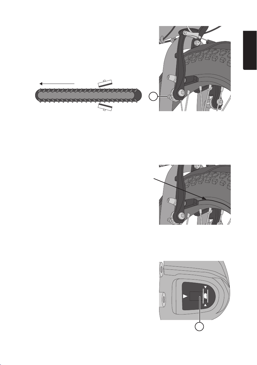
5.3 Checking for rim wear
Theeffectiveness of your brakes also depends on
thecondition of your rims. These must be checked
regularly for wear. Good rims are animportant safety
feature. Thesides of your rims come under strain during
braking and may eventually develop cracks. Because
of this your rims are equipped with wear indicators.
These are in theform of grooves etched onto theside of
therims where thebrake pads make contact.
These grooves must remain visible. Thewheels need to
be replaced once these grooves can no longer be seen.
Warning: If worn rims are not replaced, they make cause
thewheels to lock during braking which can greatly
increase therisk for personal injury.
English
6. Checking/adjusting the gears
Set theshifter (3) in second gear.
Make sure thegear indicator is between thewindow’s
(40) indicator lines. If not; adjust with thebellcrank
adjustment barrel (39) and then tighten thelock nut
behind thebarrel after adjustment.
9
SET
SET
40
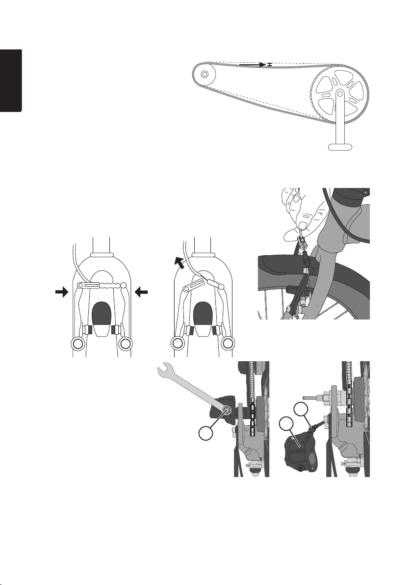
7. Checking/adjusting chain tension
English
Free play from thechain’s midpoint
should not exceed 20 mm.
Thechain will be stretched during use.
Make sure that chain tension is regularly
checked and adjusted to maintain
optimum chain tension.
8. Attaching/removing the wheels
If awheel needs to be removed, e.g. when atyre is flat, remove thebrake wire’s metal guide from
its bracket in order for thetyre to lift out freely.
• Front wheel change: Screw in theadjustment barrel
(8) on thehand brake as far as it can go. Pinch
thetwo brake arms together to remove theguide
from its bracket. Spread thebrake arms apart.
• Rear wheel change: Screw
in theadjustment barrel (8)
on thehand brake as far
as it can go. Pinch thetwo
brake arms together to
remove theguide from
its bracket. Remove the
bellcrank (37). Use a10 mm
spanner (see fig) and
loosen thebellcrank
locking screw (38) and
move thebellcrank to
theside.
Refit all thedisassembled parts in reverse order. Remember to screw theadjustment barrel (8) on
thehand brake back out again and adjust therear brakes for proper functioning after mounting
therear wheel, see the Checking/adjusting thegears section. Check wheel alignment, see
the Wheel alignment section. Ensure that re-assembly was done correctly and check that
thebrakes are functioning properly before riding.
38
39
37
10

8.1 Wheel alignment
If you tighten thechain after replacing therear wheel,
make sure that both thefront and rear wheels are aligned
with each other after assembly. Checking alignment:
From thefront of thebike, point thehandlebars straight
and using your line of sight, check that thefront and rear
tyres line up. Otherwise use astraight board butted up
against thetyres to check for alignment. If thewheels are
out of alignment with each other it will be hard to steer
and control thebike.
Ensure that re-assembly was done correctly and check
that thebrakes are functioning properly before riding.
9. Care and maintenance
• Clean your bicycle regularly. Use warm water and abrush or sponge for cleaning. Try to avoid
using ahigh pressure washer for cleaning as thewater jets may penetrate theball bearing
housing and shorten thelife of your bike.
• Regularly check that all screws and nuts are securely tightened. See 2. Product description.
• Clean thechain with abrush and dry with acloth.
• It is important that thechain, gears, wires and other moving parts are well lubricated with
proper lubrication.
• Note: Make sure that thechain is correctly tensioned. Free play from thechain’s midpoint
should not exceed 20 mm.
• Regularly check for brake wear and proper operation.
• Replace thebrake pads when worn. If thebrake pads are not completely worn, adjust
thebrake wire to improve braking performance.
• If your brakes don’t grip properly, it may be that thehandlebar post or handlebars are loose
or that your wheels are warped - leave your bike in for service at any Clas Ohlson Store or
call Clas Ohlson’s Customer Services for assistance.
• Check both front and back lights and that all reflectors are whole and clean.
• Inflate tyres to their recommended pressure as marked on your tyre’s sidewalls.
• Make sure that no sharp stones and similar objects are caught in your tyres and that there is
no other visible damage.
• Store your cycle in asheltered environment. This will prolong thelife of your cycle
considerably.
English
9.1 Winter storage
• If you need to store your bicycle for any longer period, such as in winter, it should be stored
in adry frost-free environment.
• Make sure that your tyres are properly inflated.
• Remove any batteries from your lights, otherwise there is arisk that they can leak and
cause damage.
• Make sure to wipe your rims when taking your bike out of storage as these can collect dust
and interfere with theproper functioning of your brakes.
10. Disposal
This product should be disposed of in accordance with local regulations.
If you are unsure how to proceed, contact your local council.
11

11. Specifications
English
Approx weight 14 kg
Saddle height Max 99 cm (depending on tilt angle)
Min height approx 72 cm
Handlebar height Max 105 cm (depending on tilt angle)
Min height approx 91 cm
Approx folded size 95×65×37 cm (w×h×d)
This bicycle meets European safety standard EN14764: 2005.
37 cm
65 cm
95 cm
12


Cykel 20″
Art.nr 31-8542
Läs igenom hela bruksanvisningen före användning och spara den sedan för framtida bruk.
Vi reserverar oss för ev. text- och bildfel samt ändringar av tekniska data.
Vid tekniska problem eller andra frågor, kontakta vår kundtjänst.
Svenska
Innehållsförteckning
1. Säkerhet ...............................................................................................15
2. Produktbeskrivning ........................................................................16
3. Montering ............................................................................................. 18
4. Justering ..............................................................................................19
4.1 Kontrollera/justera styrets höjd och lutning ...........................................................19
4.2 Kontrollera/justera sadelns höjd och lutning .....................................................20
5. Kontrollera/justera bromsarna..............................................20
5.1 Fälgbromsar fram/bak ........................................................................................................20
5.2 Navbroms ...................................................................................................................................21
5.3 Kontrollera fälgarnas slitage ..........................................................................................21
6. Kontrollera/justera växel ............................................................ 21
7. Kontrollera/justera kedjespänning ...................................... 22
8. Montering/demontering av hjul .......................................... 22
8.1 Hjulinställning .......................................................................................................................... 23
9. Skötsel och underhåll................................................................. 23
9.1 Vinterförvaring av cykeln ................................................................................................. 23
10. Avfallshantering ........................................................................... 23
11. Specifikationer ................................................................................ 24
14

1. Säkerhet
• Cykeln är avsedd för användning på normala vägar, den är inte avsedd för körning i terräng
eller för användning i någon form av tävlingsverksamhet. Användning på annat sätt än vad
som beskrivs här kan medföra risk för personskada eller skada på cykeln.
• Förberedelser innan användning: Ställ in rätt höjd för sadel och styre. Bekanta dig med
bromsarna, lär dig vilket bromshandtag som är för bakre resp. främre broms. Cykeln är även
utrustad med en fotbroms som aktiveras när tramporna trycks bakåt. Ta för vana att alltid
prova bromsförmågan med de olika bromssystemen på ett lämpligt ställe när du påbörjar
en cykeltur, välj en plats utan trafik eller andra hinder. Bromsa aldrig hårt med frambromsen
vid halt väglag, t.ex. på is och snö eller på regnvåt asfalt. I kraftiga nedförsbackar ska flera
bromssystem användas, annars kan navbromsen i bakhjulet överhettas.
• Kontrollera att sadelstolpen och styrstammen är inställda inom rekommenderad höjd.
De får inte vara utdragna för mycket eller för lite.
- A) Styrstammen har en märkning: MIN INSERTION vid det läge där styrstammen får
vara när den är som mest utdragen.
- B) Sadelstolpen har två märkningar: ↑ MINIMUM INSERT ↑ vid det läge där sadelstolpen
får vara när den är som mest utdragen och ↓ MAXIMUM ↓ vid det läge där den får vara
när den är som mest inskjuten.
• Rekommendationer för säker användning av cykeln – Använd cykelhjälm, kontrollera regelbundet
bromsarnas funktion och slitage samt att bromsarmen sitter fast. Kontrollera också funktion
och slitage på däck, fälgar och styrning.
• Tänk på att bromssträckan kan bli mycket längre på is, snö och regnvåt asfalt. Kontrollera
alltid innan varje användningstillfälle att cykelns snabbjusteringar för styre, styrstam och
sadelstolpe är i låst läge och att säkerhetsspärrarna för fällning av styrstam och vikning av
ram fungerar på rätt sätt.
• Maxbelastning för cykel: Max totalvikt 119 kg (cykel + användare+ bagage).
• Maxbelastning för pakethållare 15 kg.
• Maxbelastning för användare 90 kg.
• Tänk på att regler och förordningar för cyklar kan vara olika i olika länder, det kan krävas
reflexer framåt, bakåt och åt sidorna samt belysning framåt och bakåt. Ta reda på vad som
gäller i ditt land.
• Dra åt skruvar och muttrar så att de sitter säkert, men överdra inte (se 2. Produktbeskrivning).
• Ställ in cykeln så att den passar dig. Cykeln har snabbjusteringar för styre, styrstam och
sadelstolpe som gör att det är enkelt att justera så att den passar användaren.
• Gör alltid en säkerhetscheck innan användning.
• Använd alltid hjälm, hjälmen ska vara hel och rätt justerad.
• Håll alltid båda händerna på styret.
• Åk alltid i samma riktning som den övriga trafiken, åk aldrig mot trafiken.
• Följ alltid gällande trafikregler.
• Tänk på att använda kläder som gör att du syns av övriga trafikanter.
• Cykeln måste vara försedd med reflexer i hjulen, fram och bak samt på pedalerna. Se till att
cykelns reflexer är rena och väl synliga.
• Vid färd i mörker måste cykeln ha fungerande belysning både fram och bak.
• Varning! Bromsa alltid först med bakhjulsbromsen innan du bromsar med framhjulsbromsen,
detta gäller speciellt om körbanan är hal.
• Använd inte löst hängande kläder eller liknande som kan fastna i kedjan eller i hjulen när du cyklar.
• Visa hänsyn i trafiken, åk inte för nära fotgängare, ryttare eller handikappade.
Svenska
15
Varning! Cykeln är inte avsedd för att användas med barnstol eller liknande.
Varning! Som alla mekaniska komponenter, är cykeln utsatt för slitage och stora påfrestningar.
Olika material och olika komponenter kan reagera för slitage och materialutmattning på olika sätt.
Alla komponenter har en viss livslängd och om livslängden överskrids, kan en komponent plötsligt
sluta fungera och därmed medföra risk för personskada för användaren. Alla former av sprickor,
repor eller färgändring i särskilt utsatta komponenter kan påvisa att komponentens maximala
livslängd har nåtts och att den därmed ska bytas ut.
Svenska
2. Produktbeskrivning
6
8
3
7
12 9
5
4
10
11
29
Åtdragningsmoment
30
sadel 10 Nm
32
14
13
12
21 22
28
31 33
15
14
14
16 17
18 14
34
35
37
38
39
40
Åtdragningsmoment
framhjul 30–35 Nm
19
20
26
23
27
24
25 36
Åtdragningsmoment
bakhjul 35–40 Nm
16

1. Styre
2. Ringklocka
3. Växelreglage
4. Växelindikator
5. Justerskruv för växelvajer
6. Bromshandtag (ett på varje styre)
7. Handtagsjustering
8. Justerskruv för bromsvajer
9. Snabbjustering av styrets lutning
10. Vajrar (3 st.)
11. Styrstam
12. Snabbjustering av styrstammens höjd
13. Snabbkoppling med spärr för vikning av styrstam
14. Reflexer (fram, bak, hjulen och pedalerna)
15. Främre fälgbroms
16. Justerskruv för fjäderspänning till bromsarm
17. Bromsbelägg
18. Framgaffel
19. Framhjul
20. Däck
21. Ram
22. Snabbkoppling med spärr för vikning av ram
23. Vevarm
24. Pedal
25. Kedja
26. Kedjeskydd
27. Stöd
28. Sadelstolpe
29. Sadel
30. Sadelns klämbult
31. Snabbjustering av sadelstolpens höjd
32. Bakre fälgbroms
33. Pakethållare
34. Bakhjul
35. Nav med navbroms
36. Navbromsens bromsarm
37. Växel
38. Låsskruv för växel
39. Justerskruv för växel
40. Fönster för växeljustering
Svenska
17
3. Montering
Cykeln kommer färdigmonterad men hopvikt.
Svenska
Vik upp cykeln så här:
13
13
Vik upp styrstammen. Tryck snabbkopplingen (13) uppåt så att den
Vik ut ramen. Ta tag i pedalerna och vik ut dem.
låser fast styrstammen. Kontrollera att snabbkopplingens spärr har gått i lås. Kontrollera
att spärren håller i så att det inte går att öppna
snabbkopplingen utan att hålla in spärren.
18
Tryck snabbkopplingen (22) framåt så att den låser
ihop ramen. Kontrollera att snabbkopplingens spärr
har gått i lås. Kontrollera att spärren håller i så att
det inte går att öppna snabbkopplingen utan att
hålla in spärren.
22
4. Justering
4.1 Kontrollera/justera styrets höjd och lutning
Styrets höjd och lutning kan justeras så att det passar användaren. Dra upp styrstammen och
sadelstolpen till en höjd som du tror är lagom. Sätt dig på sadeln och känn efter om höjden är
rätt så att du når ner till marken.
Varning! Snabbjusteringen för styrstammens höjd (eller vikning) får inte röras under pågående
cykling, all justering måste ske stillastående.
Styrstammen (11) har en snabbjustering (12) som gör det enkelt att ställa in styrets höjd.
Den har också en snabbjustering (9) för styrets lutning.
Styrstammen har en viktig märkning: MIN INSERTION
vid det läge där styrstammen får vara när den är som
mest utdragen. Obs! Markeringen IIIIIIIIIIIIIIIIIII ovanför
texten på sadelstolpen ska synas ovanför ramröret.
Svenska
Styrets höjd ska ställas in så att användaren har en
bekväm ställning vid cykling. Justera styrets lutning vid
behov; öppna snabbjusteringen (9) och ställ in önskad
lutning. Kontrollera att alla reglage på styret fungerar efter
inställning.
Kom ihåg att låsa alla snabbjusteringar innan du börjar cykla!
19
9
12
4.2 Kontrollera/justera sadelns höjd och lutning
Höjdjusteringen kan göras efter att snabbjusteringen (30)
har lossats.
Obs! Sadelstolpen har två märkningar:
↑MINIMUMINSERT↑ vid det läge där sadelstolpen får
vara när den är som mest utdragen och ↓ MAXIMUM↓
vid det läge där den får vara när den är som mest inskjuten.
Svenska
Obs! Markeringen IIIIIIIIIIIIIIIIIII ovanför texten på sadelstolpen ska synas ovanför ramröret.
Sadelhöjden ska ställas in så att foten, med benet nästan
helt utsträckt, kan sättas ned mitt på pedalen när den är
i nedersta pedalläget. Då ska man dessutom kunna röra
vid marken med tårna.
Sadeln (29) ska ställas in horisontellt eller eventuellt så
att den lutar något bakåt. Önskad lutning på sadeln är
individuellt, och det kan krävas en lång cykeltur för att
hitta den bekvämaste sittställningen.
Lutningen på sadeln kan ändras efter att sadelns
klämbult (30) har lossats. Justera sadeln framåt eller bakåt.
Kom ihåg att dra åt alla skruvar som lossats för inställningen,
innan du börjar cykla!
Varning! Kontrollera alltid innan varje användningstillfälle
att snabbkopplingarna för vikning av ram (22) och styrstam (13) är låsta och att spärrarna fungerar!
30
5. Kontrollera/justera bromsarna
5.1 Fälgbromsar fram/bak
Kontrollera att fälgsidorna är hela och rena och fria från fett.
Kontrollera fälgbromsarna regelbundet så här: dra in bromshandtaget och kontrollera att vajerns
ytterhölje är helt, att båda bromsbeläggen går emot fälgkanten samtidigt och att inte bromshandtaget går att dra ända in mot handtaget.
Justera fälgbromsarna vid behov.
• Justera bromsbeläggen (17) så att de endast ligger
an mot fälgen och inte mot däcket på något sätt
vid bromsning.
• Avståndet mellan bromsbeläggen och fälgsidan bör
vara 1–2 mm, justera avståndet med justerskruven (8)
vid handtaget.
20
8
 Loading...