


 Loading...
Campus Wireless Networks
Validated Reference Design
Version 3.3
Design Guide

Copyright
© 2008 Aruba Networks, Inc. All rights reserved.
Trademarks
AirWave®, Aruba Networks®, Bluescanner®, For Wireless That Works®, Mobile Edge Architecture®, People Move. Networks Must Follow., RFProtect®, The All Wireless Workplace Is Now Open For Business, and The Mobile Edge Company® are trademarks of Aruba Networks, Inc. All rights reserved.
Legal Notice
The use of Aruba Networks, Inc. switching platforms and software, by all individuals or corporations, to terminate other vendors' VPN client devices constitutes complete acceptance of liability by that individual or corporation for this action and indemnifies, in full, Aruba Networks, Inc. from any and all legal actions that might be taken against it with respect to infringement of copyright on behalf of those vendors.
Warranty
This hardware product is protected by the standard Aruba warranty of one year parts/labor. For more information, refer to the ARUBACARE SERVICE AND SUPPORT TERMS AND CONDITIONS.
Altering this device (such as painting it) voids the warranty.
www.arubanetworks.com
1322 Crossman Avenue
Sunnyvale, California 94089
Phone: 408.227.4500
Fax 408.227.4550
Campus Wireless Networks Validated Reference Design Version 3.3 | Design Guide |
March 2008 |

Contents
Chapter 1 |
Introduction |
5 |
|
Aruba Reference Architectures |
5 |
|
Reference Documents |
5 |
|
Contacting Aruba Networks |
5 |
Chapter 2 |
Aruba’s User-Centric Network Architecture |
7 |
|
Understanding Centralized Wireless LAN Networks |
7 |
|
Introducing Aruba’s User-Centric Network |
8 |
|
ArubaOS and Mobility Controller |
9 |
|
ArubaOS |
9 |
|
Mobility Controller |
10 |
|
Multi-function Thin Access Points |
11 |
|
Access Point |
11 |
|
Air Monitor |
11 |
|
Mesh Portal or Mesh Point |
12 |
|
Aruba’s Secure Enterprise Mesh Network |
12 |
|
Remote AP |
13 |
|
Mobility Management System |
13 |
|
Mobility Management System |
14 |
Chapter 3 |
A Proof-of-Concept Network |
15 |
|
PoC Network - Physical Design |
15 |
|
PoC Network - Logical and RF Design |
16 |
Chapter 4 |
Campus WLAN Validated Reference Design |
19 |
|
Aruba Campus WLAN Physical Architecture |
19 |
|
Aruba Campus WLAN Logical Architecture |
20 |
|
Other Aruba Reference Architectures |
21 |
Chapter 5 |
Mobility Controller and Access Point Deployment |
23 |
|
Understanding Master and Local Operation |
23 |
|
Mobility Controller High Availability |
24 |
|
Master Controller Redundancy |
25 |
|
Local Controller Redundancy |
26 |
|
VLAN Design |
28 |
|
Do Not Make Aruba the Default Router |
29 |
|
Do Not Use Special VLANs |
29 |
|
VLAN Pools |
30 |
|
User Mobility and Mobility Domains |
31 |
|
ArubaOS Mobility Domain |
32 |
|
Mobility Controller Physical Placement and Connectivity |
33 |
|
Master Controller Placement |
33 |
|
Local Controller Placement |
34 |
|
AP Placement, Power, and Connectivity |
34 |
|
Mobility Controller and Thin AP Communication |
34 |
|
AP Power and Connectivity |
35 |
Campus Wireless Networks Validated Reference Design Version 3.3 | Design Guide |
Contents | 3 |

|
AP Location and Density Considerations |
35 |
|
Office Deployment |
35 |
|
Voice Deployment |
36 |
|
Active RFID Tag Deployment |
36 |
Chapter 6 |
Mobility Controller Configuration |
37 |
|
Required Licenses |
37 |
|
Configuration Profiles and AP Groups |
37 |
|
Configuration Profiles |
37 |
|
Profile Types |
38 |
|
AP Groups |
39 |
|
Profile Planning |
39 |
|
SSIDs, VLANs and Role Derivation |
39 |
|
SSIDs |
40 |
|
VLANs |
40 |
|
Role Derivation |
41 |
|
Secure Authentication Methods |
41 |
|
Authenticating with 802.1X |
42 |
|
Authenticating with Captive Portal |
44 |
|
Authentication Methods for Legacy Devices |
44 |
|
Configuring Roles for Employee, Guest and Application Users |
45 |
|
Employee Role |
45 |
|
Guest Role |
46 |
|
Device Role |
50 |
|
Role Variation by Authentication Method |
51 |
|
Wireless Intrusion Detection System |
51 |
|
Wireless Attacks |
51 |
|
Rogue APs |
52 |
Chapter 7 |
RF Planning and Operation |
55 |
|
RF Plan Tool |
55 |
|
Adaptive Radio Management |
56 |
Chapter 8 |
Voice over Wi-Fi |
59 |
|
WMM and QoS |
59 |
|
Quality of Service |
59 |
|
Traffic Prioritization |
60 |
|
Network Wide QoS |
60 |
|
Voice Functionality and Features |
60 |
|
Voice-Aware RF Management |
60 |
|
Call Admission Control |
60 |
|
Comprehensive Voice Management |
61 |
Chapter 9 |
Controller Clusters and the Mobility Management System™ |
63 |
Appendix A |
Licenses |
67 |
Appendix B |
WLAN Extension with Remote AP |
69 |
Appendix C |
Alternative Deployment Architectures |
71 |
|
Small Network Deployment |
71 |
|
Medium Network Deployment |
72 |
|
Branch Office Deployment |
73 |
|
Pure Remote Access Deployment |
75 |
4 | Contents |
Campus Wireless Networks Validated Reference Design Version 3.3 | Design Guide |

Chapter 1
Introduction
This design guide is one of a series of books that describes Aruba’s User-Centric Network Architecture and provides network administrators with guidelines to design and deploy a centralized enterprise-wide wireless LAN (WLAN) network for the most common customer scenarios.
This guide complements the technical documentation you received with software and hardware releases for Aruba components.
Aruba Reference Architectures
An Aruba Validated Reference Design (VRD) is a package of network decisions, deployment best practices, and detailed descriptions of product functionality that comprise a reference model for common customer deployment scenarios. The VRD presented in this guide is representative of a best practice architecture for a large Campus WLAN serving thousands of users spread across many different buildings joined by SONET, MPLS, or other high-speed, high-availability network backbone.
The Campus Wireless Network is one of five reference architectures commonly deployed by our customers. For a brief description of the other deployment models refer to Appendix C, “Alternative Deployment Architectures” on page 71.
Reference Documents
Refer to the following documentation for more detailed technical information about Aruba OS.
Title |
Version |
|
|
ArubaOS User Guide |
3.3.1 |
|
|
ArubaOS CLI Guide |
3.3.1 |
|
|
ArubaOS Release Note |
3.3.1 |
|
|
ArubaOS Quick Start Guide |
3.3.1 |
|
|
MMS User Guide |
2.5 |
|
|
MMS Release Notes |
2.5 |
|
|
Contacting Aruba Networks
Web Site Support
Main Site |
http://www.arubanetworks.com |
|
|
Support Site |
http://www.arubanetworks.com/support |
|
|
Software Licensing Site |
https://licensing.arubanetworks.com |
|
|
Wireless Security Incident Response Team (WSIRT) |
http://www.arubanetworks.com/support/wsirt |
|
|
Support Email |
support@arubanetworks.com |
|
|
WSIRT Email |
wsirt@arubanetworks.com |
Please email details of any security problem found in an |
|
Aruba product. |
|
|
|
Campus Wireless Networks Validated Reference Design Version 3.3 | Design Guide |
Introduction | 5 |

Telephone Support
Aruba Corporate |
+1 (408) 227-4500 |
||
|
|
||
FAX |
+1 (408) 227-4550 |
||
|
|
|
|
Support |
|
|
|
United States |
800-WI-FI-LAN (800-943-4526) |
||
France |
+33 |
(0) |
1 70 72 55 59 |
United Kingdom |
+44 |
(0) |
20 7127 5989 |
Germany |
+49 |
(0) |
69 38 09 77 22 8 |
All Other Countries |
+1 (408) 754-1200 |
||
|
|
|
|
6 | Introduction |
Campus Wireless Networks Validated Reference Design Version 3.3 | Design Guide |

Chapter 2
Aruba’s User-Centric
Network Architecture
This chapter provides an overview of a centralized wireless LAN architecture, followed by a high level technical overview of the Aruba User-Centric Network components and network design.
This overview describes the technology, architecture, services, and applications that make up an Aruba User-Centric Network to help you make the right design choices, and select the appropriate solution components.
Understanding Centralized Wireless LAN Networks
In the early days of wireless LAN (WLAN) networks, Access Points operated in an autonomous fashion much like other routers and switches in the network. Access Points were managed and maintained independently; which worked for very small wireless deployments, such as lobbies and conference rooms where guests were expected.
Client |
Autonomous |
Access |
Distribution |
termination |
|||
point |
AP |
layer |
layer |
Encryption
arun_030
As large numbers of regular enterprise users began to expect connectivity using wireless connections, the autonomous Access Points became a management, reliability and security headache. Maintaining consistent configurations for dozens or hundreds of standalone APs became time-consuming, and introduced errors. Because each AP was a standalone device, network availability could not be guaranteed if any single AP failed. Centralized management consoles also fell short of expectations; and, in general, never grew beyond a certain point due to escalating operational costs. The workload associated with maintaining security, managing and troubleshooting large numbers of APs created a barrier to adoption in the larger enterprise; except in niche applications, such as guest access in conference rooms.
From a security perspective, users did not experience true mobility because network managers addressed WLAN security issues by treating wireless users and remote dial-up users the same way. Oftentimes, wireless users are quarantined on a single VLAN and forced through the “de-militarized zone” (DMZ) residing outside the corporate intranet. Users are then expected to tunnel into the corporate network through VPN concentrators that support industrial strength encryption such as AES.
A VPN was required primarily because of the ‘port-based security’ limitation of modern enterprise network infrastructures. VLANs and access controls are specified at the port level. When an autonomous AP is plugged in, then all users who connect to that AP inherit those security settings whether they are supposed to have them or not.
VPNs were a rudimentary way to impose identity-based authentication and provide extra encryption for first-generation wireless security systems. Unfortunately, these VPN concentrators were optimized for low speed WAN connections not intended for large numbers of high-speed wireless LAN users which then resulted in poor performance, management complexity, mobility, and scalability problems.
Campus Wireless Networks Validated Reference Design Version 3.3 | Design Guide |
Aruba’s User-Centric Network Architecture | 7 |

Introducing Aruba’s User-Centric Network
In recent years, controller-based wireless switch architectures have been widely adopted to overcome the limitations of the autonomous AP. The Aruba centralized WLAN model shown below represents a structured model for WLAN deployment and ongoing management using a holistic approach to build enterprise WLANs that support user mobility without sacrificing security, manageability and scalability.
The Aruba User-Centric Network is an “overlay” network consisting of a centralized Mobility Controller and thin APs that work together over an existing high-speed network. Most enterprise networks have been engineered for high performance and high reliability, therefore, deploying the Aruba User-Centric Network as an overlay will not adversely affect the investment and reliability of the existing network.
With this approach, a centralized appliance controls hundreds or thousands of network-attached radios in a secure, reliable manner. This model represents a unified mobility solution integrating user mobility, identity based security, remote access, and enterprise fixed mobile convergence (eFMC) solutions.
Centralized WLAN Model
Client |
|
|
|
termination |
|
Mobility |
|
point |
Thin AP |
||
controller |
|||
|
Encryption |
|
|
|
|
Tunnel |
|
|
|
arun_031 |
In this system, the intelligence that once resided in autonomous APs is now integrated into a centralized WLAN Mobility Controller designed for high-performance 802.11 packet processing, mobility and security management. These controllers are typically deployed in secured data center environment or distribution closets with redundant power and connectivity. APs are simplified and become networkattached radios that perform only transceiver and air monitoring functions. These access points are commonly referred to as “thin” APs. Connected to the Mobility Controller directly or over a layer 2/3 network by encrypted tunnels, they become extended access ports on the Mobility Controller directing user traffic to the controller for processing; while providing visibility and control of the RF environment to protect against intrusions (such as unauthorized users or rogue APs).
8 | Aruba’s User-Centric Network Architecture |
Campus Wireless Networks Validated Reference Design Version 3.3 | Design Guide |

ArubaOS and Mobility Controller
This section describes Aruba’s operating system features, optional add-on modules and the Mobility Controller that comprise Aruba’s User-Centric Network Architecture.
ArubaOS
The ArubaOS serves as the operating system and application engine for all Aruba Mobility Controllers, and is the core component that enables user-centric networks. Standard with every Aruba Mobility Controller, ArubaOS provides unprecedented control over the entire mobile environment enabling Aruba’s unique adaptive wireless LANs, identity-based security, and application continuity services.
The main features of ArubaOS include:
zSophisticated authentication and encryption
zProtection against rogue wireless APs
zSeamless mobility with fast roaming
zAdaptive RF management and analysis tools
zCentralized configuration
zLocation tracking and more
ArubaOS also offers the following optional add-on modules that provide advanced capabilities including wireless intrusion protection (WIP), identity-based security with user-centric policy enforcement, mobile Network Access Control (NAC), secure remote access, and advanced network connectivity technologies.
zWireless Intrusion Protection
zPolicy Enforcement Firewall
zVPN Server, Remote AP
zExternal Services Interface
zVoice Services Module
zWireless Mesh, and xSec Advanced L2 Encryption.
A complete description of all software modules is available in Appendix A, “Licenses” on page 67 of this document.
Campus Wireless Networks Validated Reference Design Version 3.3 | Design Guide |
Aruba’s User-Centric Network Architecture | 9 |

Mobility Controller
The Aruba Mobility Controller is the center of the User-Centric Network. The Mobility Controller is a part of a purpose built, scalable appliance family that runs the ArubaOS operating system and software modules. It provides network administrators the ability to manage the system state and rapidly scope problems for individual users across a single Master/Local controller cluster in a network. Refer to the Aruba Mobility Management System (MMS) in Chapter 9, “Controller Clusters and the Mobility Management System™” on page 63 to manage more than one Master/Local Controller cluster.
The Mobility Controller provides advanced RF features that take guess work and maintenance out of maintaining a wireless LAN. With RF Plan, a predictive site survey can be performed with nothing more than a floor plan and coverage requirements. Once installed, the system’s Adaptive Radio Management (ARM) takes over. This distributed and patented algorithm runs to constantly monitor the RF environment, and adjust AP power and channel settings without user intervention; even in the face of interference or AP failure. RF Live shows the actual real time coverage using “heat maps” overlaid on the floor plan, while RF Locate allows Wi-Fi® clients and active RFID tags to be triangulated on the same set of floor plans.
Once the RF is running, security is initiated. Aruba Mobility Controllers use a multi-layered system to provide continuous protection of the network. The system constantly scans the environment looking for threats to users, and takes proactive action to contain rogue access points and potential attackers. Strong encryption and authentication techniques are routinely used to ensure users can safely connect to the network and that all transmissions are secure. The Mobility Controller uses a stateful firewall to monitor client traffic for policy violations and to provide high touch services.
Now that RF is present and secure, users are ready to roam the enterprise. Aruba’s IP Mobility feature provides the capability for users to roam the enterprise without losing their connection or changing their IP address, even when moving between APs or controllers. This is critical when the organization moves to Voice over WLAN and dual mode phones.
10 | Aruba’s User-Centric Network Architecture |
Campus Wireless Networks Validated Reference Design Version 3.3 | Design Guide |
Multi-function Thin Access Points
Aruba’s access points serve multiple functions depending on their role in the network. APs are either indoor or outdoor deployable; and are available with various options, such as fixed or removable antennas, single or dual radio APs, and depending on the AP, can operate in one or more of the a/b/g/n spectrums. Selection of hardware based options should be considered depending on the deployment.
Functionality is defined by the role assigned through software modules and administrator configuration. Each radio on an Aruba AP can serve in one of five different roles. These roles include:
zAccess Point (Local AP)
zAir Monitor
zMesh Portal
zMesh Point
zRemote AP
In some modes, the Aruba APs can operate as remote capture devices saving the network staff from having to walk to a problem area to use a handheld sniffer for troubleshooting.
Access Point
The most typical deployment uses an Aruba AP in the Access Point role. In this role, the AP radio(s) are used to connect user to the network infrastructure. The AP acts as a thin radio with much of the functionality of the system taking place on the Mobility Controller. Traffic is not processed on the AP. Instead, it is tunneled as an encrypted 802.11 frame to the controller via GRE. When an AP is connected to access layer switches it is known as a “campus-connected” or “local” AP.
Air Monitor
Used as an Air Monitor, the AP works as a network sniffer. The air monitor looks for rogue APs, monitors the RF environment and wired environment, and when combined with the wireless intrusion detection system (WIDS) software license it acts as a WIDS sensor to protect the network from those violating policy. The system can classify interfering and rogue APs based on network traffic and RF monitoring. Aruba APs can be dedicated to the Air Monitor function or can perform this role on a parttime basis when configured in the Access Point role.
Campus Wireless Networks Validated Reference Design Version 3.3 | Design Guide |
Aruba’s User-Centric Network Architecture | 11 |

Aruba recommends using dedicated Air Monitors for deployments of latency sensitive applications such as voice and video. Typically, one Air Monitor can provide security to the area served by up to four Access Points.
Mesh Portal or Mesh Point
In the Mesh Portal or Mesh Point role, the AP is taking part in Aruba’s secure enterprise mesh network. This network is based around a single AP (the Mesh Portal) with a wired network connection, and one or more Mesh Point APs performing wireless backhaul or bridging of network traffic.
When used with dual radio APs, the mesh devices can provide client access on one radio and backhaul on the second. User traffic is authenticated and protected by the same centralized encryption method as wired APs, while Control traffic is protected by WPA2 authentication and encryption.
Aruba’s Secure Enterprise Mesh Network
|
WLAN RF |
Mesh |
|
point |
|
|
coverage |
|
|
|
|
|
|
Mesh RF |
Mesh |
|
coverage |
point |
|
Mesh |
|
|
|
|
|
portal |
|
|
Mesh |
|
|
point |
Mesh


 point
point 


 Mesh
Mesh
portal
Mesh
 point
point 
arun_032
12 | Aruba’s User-Centric Network Architecture |
Campus Wireless Networks Validated Reference Design Version 3.3 | Design Guide |
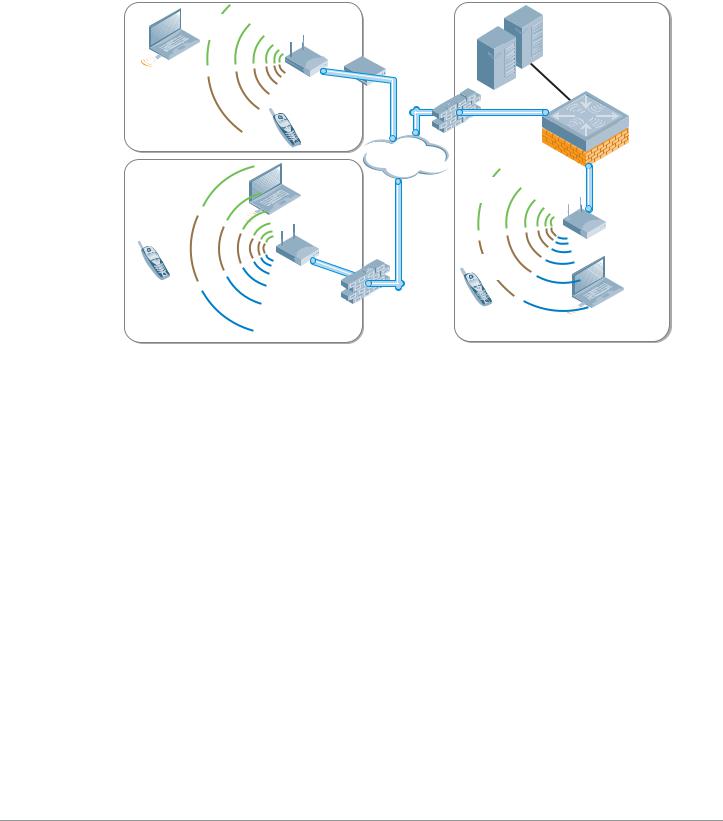
Remote AP
Using the Remote AP license, the AP can be used as a remote access device across a WAN. Plugging in to any Internet capable Ethernet port, the AP will create a secure tunnel using IPSec (AES) to a designated Mobility Controller. Typically this is done at corporate headquarters, or in regional data centers around the world for global deployments. The same SSIDs, authentication, and security are then available anywhere in the world.
Corporate |
Data Center |
SSID |
DSL/cable |
|
|
|
modem |
|
|
Aruba |
|
Voice |
Remote |
Mobility |
|
AP |
Controller |
||
SSID |
|||
|
|
Home Office |
VoIP |
Firewall |
|
|
Internet |
Corporate |
|
Corporate |
|
SSID |
|
|
|
|
SSID |
|
|
|
|
Aruba |
|
|
|
|
|
Voice |
Remote |
IPsec |
AP |
SSID |
AP |
tunnel |
|
|
|
Voice |
Guest |
|
|
SSID |
SSID |
Guest |
|
Firewall |
|
SSID |
|
|
|
Branch Office |
|
VoIP |
Corporate HQ |
|
|
arun_033
This provides an on-demand corporate hotspot with the same security and access to resources that users will find at the corporate campus without having to install additional software or be subject to a software learning curve. Unlike a software VPN that provides only a limited set of services, using the Aruba Remote AP license extends the entire corporate WLAN experience with the same powerful UserCentric Security.
Mobility Management System
Wireless networking doesn’t make the IT administrator’s job easier; in fact, it can make the job considerably harder. There are no longer any wires to trace, and IP address information only tells you where that user started their day. The MMS consists of a new set of tools to help administrators understand and visualize the wireless network they are administering. It is designed to provide network administrators with the ability to effectively manage multiple Master/Local clusters in the network. The user-centric management model allows administrators to rapidly visualize all network objects related to the user in real-time; drastically reducing the mean-to-resolution (MTTR) while ensuring a high quality WLAN user experience.
The Mobility Management System™ consists of a built-in location API that enables external systems to query the location of any WLAN device. The Mobility Management System software can be deployed on any PC platform (Linux or Windows 2003) or as an option, can be purchased as an enterprise class, hardened appliance.
One controller in each Aruba deployment is designated as the Master Controller. The Master Controller can also manage “Local” controller pairs, or clusters, in a high-availability configuration. However, once
Campus Wireless Networks Validated Reference Design Version 3.3 | Design Guide |
Aruba’s User-Centric Network Architecture | 13 |

the network grows to multiple clusters, a single centralized view across multiple Master/Local controllers of the following key operational data becomes highly desirable.
zUsers on wireless network
zAPs that users are connected to
z802.11 traffic statistics
zAP failure notifications
zFailover alternatives and backup coverage maps
Mobility Management System
Refer to Chapter 9, “Controller Clusters and the Mobility Management System™” on page 63 for more detailed information.
14 | Aruba’s User-Centric Network Architecture |
Campus Wireless Networks Validated Reference Design Version 3.3 | Design Guide |

Chapter 3
A Proof-of-Concept Network
To help set the stage for the complex campus network presented in Chapter 4 on page 19, it is useful to begin with a very small network. In this chapter, we consider a network that is typically deployed in a Proof-of-Concept (PoC) test involving a handful of Access Points and a Master Controller that provides guest and employee coverage to a conference room.
PoC Network - Physical Design
To keep the example as simple as possible, the design of this network involves a single AP and a single Mobility Controller, and uses an existing RADIUS or LDAP server for authentication.
Distribution
switches
Internet
Firewall
Data center
Mobility |
File |
|
Web |
||
controller |
||
|
PBX |
|
|
RADIUS |
Core
Distribution
Access
Edge
APs
Employee |
|
Guest |
SSID |
Application |
SSID |
|
SSID |
arun_034 |
Campus Wireless Networks Validated Reference Design Version 3.3 | Design Guide |
A Proof-of-Concept Network | 15 |

In this network, the AP has been deployed into a conference room, and is connected to the existing VLAN provided for wired users. In keeping with the concept of a network overlay, no reconfiguration or special VLANs need to be created as long as the access point has IP connectivity to the Mobility Controller.
PoC Network - Logical and RF Design
A common feature of centralized WLAN architectures is the ability to support many Service Set Identifiers (SSIDs) simultaneously from the same APs. Each SSID can have its own authentication and encryption settings based on the capabilities of the clients and the services that each needs. In this PoC network there are three SSIDs available for association via the AP.
zEmployee
zGuest
zApplication
|
Data center |
|
Data center |
File |
|
Data center |
File |
||||||
|
|
|
File |
|
|
|
|
|
|
|
Web |
||
|
|
|
|
|
|
|
|
|
|
|
|||
|
|
|
Web |
|
|
|
|
|
|
|
|
|
PBX |
|
|
|
|
|
|
|
Web |
|
|
|
|
|
|
|
|
|
|
|
|
|
|
|
|
|
|
|
|
|
|
|
PBX |
|
|
|
PBX |
|
|
|
|
RADIUS |
|
|
|
|
|
|
|
RADIUS |
|
|
|
|
|
||
|
|
|
RADIUS |
|
|
|
|
|
|
|
|
|
|
Internet |
|
|
|
Internet |
|
|
|
|
|
|
|
|
|
|
|
|
|
|
|
|
|
|
|
|
|
|
|
Guest |
Employee |
Application |
|
VLAN |
VLAN |
VLAN |
|
|
Employee |
Guest |
|
|
SSID |
|
|
|
|
SSID |
|
Employee |
Guest SSID |
Guest |
Employee |
SSID Application |
Application SSID |
SSID |
|
SSID |
|
SSID |
|
Application SSID
Data center
File
PBX |
Web |
RADIUS |
Internet
Guest
SSID
Employee |
|
SSID |
Application |
|
SSID |
arun_038
16 | A Proof-of-Concept Network |
Campus Wireless Networks Validated Reference Design Version 3.3 | Design Guide |

Users will associate to the Access Point and authenticate with the RADIUS server that already exists in the network. Employee users will use the Employee SSID, while guests will use the Guest SSID. Voice and data devices will associate to the Application SSID, and will be given a role based on the network services they are capable of accessing.
Each user and device has a specific role and associated policy enforced by the stateful firewall in the Mobility Controller. The Employee user now has full access to all resources within the network and the internet. Guest users are only permitted to access the Internet using specific protocols such as HTTP and HTTPS. Application devices are only able to access related application servers; for example, a phone running SIP can only access the SIP server to make calls.
This simple network describes the overlay functionality of an Aruba network, and shows how network control and policy enforcement is built into the fabric of the system. Users are only able to access those resources they have permissions for, and only after they have successfully authenticated to the network. This is the definition of an Aruba User-Centric Network.
Campus Wireless Networks Validated Reference Design Version 3.3 | Design Guide |
A Proof-of-Concept Network | 17 |

18 | A Proof-of-Concept Network |
Campus Wireless Networks Validated Reference Design Version 3.3 | Design Guide |

Chapter 4
Campus WLAN Validated
Reference Design
This chapter presents a more complex network model representing a common Aruba deployment in a large campus WLAN environment.
Enterprise networks support thousands of employees, with rigorous service level expectations. To meet these requirements, a reference wired network architecture that defines Core, Distribution and Access elements has become well established among IT network professionals. These elements form the building blocks of large scale, highly-available networks. Vendor validation of their products against this conceptual reference architecture provides IT organizations with assurance that products will perform and interoperate as expected.
Aruba User-Centric Enterprise Wireless Networks also support large numbers of users with stringent service level expectations. To enable IT network architects to successfully plan deployments, Aruba has developed a Validated Reference Design (VRD) that leverages the experience of more than 3,500 customer deployments, peer-review by Aruba engineers, and extensive performance testing. This reference design leverages and extends the familiar wired model in order to deploy a user-centric network as an overlay.
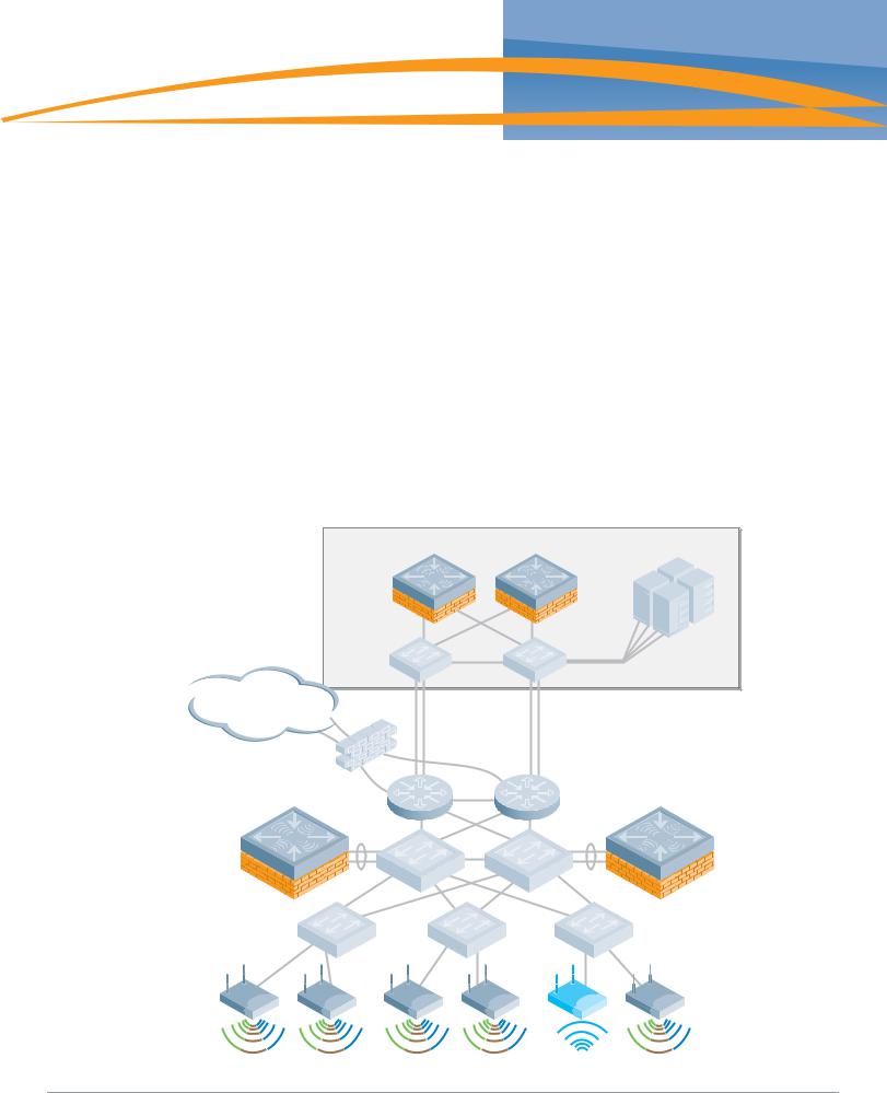
Aruba Campus WLAN Physical Architecture
The Validated Reference Design network model described in this chapter is referenced throughout the remainder of this book. The model depicts a cluster-based architecture typical of large enterprise deployments. For this type of deployment it is a best practice to employ distributed control and data planes using a hierarchical ‘Master/Local’ strategy with separate controller clusters providing each service. This will provide a scalable highly available architecture for data and voice traffic throughout the enterprise.
Some key components of this reference model include:
zMaster Controllers – Two MMC-3600 model appliances configured to use Master redundancy. Each controller has redundant gigabit Ethernet links into the data center distribution switches, and share a Virtual Router Redundancy Protocol (VRRP) address.
zLocal Controllers – Aruba Local Controllers consist of Multiservice Mobility Module blades in an MMC-6000 chassis. In the Aruba VRD, these Mobility Controllers are running in “active-active” redundancy, with two VRRP addresses shared between them. Each controller has two 10 gigabit Ethernet links bonded via Etherchannel to a single distribution layer switch.
zAccess Points – Dual radio (A/B/G) AP65 access points are deployed throughout the enterprise carpeted space, providing high bandwidth access across the 2.4 GHz and 5Ghz bands. These APs are densely deployed. “Dense Deployment” uses a microcell architecture to cover an area using overlapping APs at relatively low transmit power. This design strategy enables ARM to detect and close coverage holes in the event of an AP failure by increasing power on neighboring APs. Smaller cells also help ensure proper load balancing of Voice over WLAN callers.
zSSIDs – There are three Service Set Identifiers present in the Reference Design. One SSID is used for employees and runs WPA2 for authentication and encryption. A second SSID is used by applications such as voice or video, and runs WPA with a Pre-Shared Key for authentication and encryption. The final SSID is open with a web based captive portal for authentication and is used by guests. Each user or device that associates with the network is placed in a role that is enforced by the stateful firewall.
Campus Wireless Networks Validated Reference Design Version 3.3 | Design Guide |
Campus WLAN Validated Reference Design | 19 |

zAir Monitors – AMs are deployed at a ratio of one AM for every four APs deployed. These handle many of the IDS related duties for the network, and will assist in drawing accurate heat maps displaying graphical RF data. Aruba considers dedicated Air Monitors to be a security best practice because they provide full time surveillance of the air.
|
Data center |
Master |
File |
Web |
|
active |
Master |
|
|
|
standby |
|
PBX |
|
RADIUS |
Internet
Local |
Local |
Air monitor
arun_040
Aruba Campus WLAN Logical Architecture
From a logical perspective, the VRD overlay introduces three new terms into the familiar “core/ distribution/access” framework. They are “Management,” “Aggregation” and "Wireless Access.”
zManagement
The Management layer provides a distributed control plane for the Aruba User-Centric Network that spans the physical geography of the wired network. Critical functions provided by the Management Layer Mobility Controllers include L3 client mobility across Aggregation layer controllers, and failover redundancy. Typically, larger networks, such as campus systems also off load ARM and IDS processing from the Aggregation Layer to the Management Layer.
zAggregation
The Aggregation layer is the interconnect point where wireless traffic is aggregated and enters or exits the wired network. Secure encrypted GRE tunnels from APs at the Wireless Access layer terminate on controllers at the Aggregation layer. This provides a logical point for enforcement of roles and policies, and is where the ArubaOS creates the User-Centric Network Experience.
20 | Campus WLAN Validated Reference Design |
Campus Wireless Networks Validated Reference Design Version 3.3 | Design Guide |
Aggregation Layer Mobility Controllers allow user traffic to stay close to associated servers; there is no need to tunnel user traffic all the way to the Management layer.
zWireless Access
The Wireless Access layer is comprised of APs: single or dual-band, 802.11a/b/g or n, indoor or outdoor. They can be connected using wired switch ports, secure mesh or Remote AP.
|
|
Data center |
File |
|
|
|
|
|
|
|
Web |
Management |
Master |
Master |
|
|
active |
standby |
PBX |
|
|
|
|
|
|
|
RADIUS |
Control
Aggregation |
Local |
Local |
Data
Wireless |
Access |
Air monitor
arun_046
Together, the Management, Aggregation, and Wireless Access layers overlay on the Core, Distribution and Access infrastructure in a seamless, secure and high-performance manner. Any Aruba controller can serve as in the Management and Aggregation layer, and in smaller networks, a single controller provides both functions.
The network architect typically chooses the controller model that has capacity appropriate to the size of the user and AP population. In contrast to the Core/Distribution/Access model with capacity increasing as you approach the Core; a User-Centric network requires more capacity in the middle layer where tunnels are terminating and policies are being applied.
Other Aruba Reference Architectures
This Campus Wireless LAN Reference Architecture represents a large scale, highly available WLAN deployment model for a campus environment with numerous buildings that house thousands of users. This is the recommended deployment for this environment. There are other reference architectures that are considered best practices at different scales, and for different types of customer scenarios. Other Reference Architecture models that are commonly deployed by our customers are described in Appendix C on page 71.
Campus Wireless Networks Validated Reference Design Version 3.3 | Design Guide |
Campus WLAN Validated Reference Design | 21 |

22 | Campus WLAN Validated Reference Design |
Campus Wireless Networks Validated Reference Design Version 3.3 | Design Guide |
Chapter 5
Mobility Controller and
Access Point Deployment
Deployment of the Mobility Controller must be considered based on a number of factors; the most important of which is identifying where user traffic is ultimately destined. The Validated Reference Design for Campus Wireless Networks depicts the Master Controllers residing in the data center and Local Controllers deployed at the distribution layer.
Understanding Master and Local Operation
Once the controller count grows beyond a single pair of controllers, change control and network consistency can become an issue. To solve this management scalability issue, Mobility Controllers can be deployed in clusters consisting of a Master and one or more Local Controllers.
The Master Mobility Controller resides at the Management layer of the Aruba architecture in a data center environment. In an Aruba network employing a Master/Local design, configuration is performed on the Master and pushed down to the Locals. User troubleshooting, RF planning, and real-time RF visualization take place on the Master. The Master also controls Adaptive Radio Management (ARM) decisions for all Local controllers and is responsible for radio power and channel settings at the Wireless Access layer.
Data center |
|
|
|
|
File |
Master |
|
Web |
|
|
|
Mobility |
|
|
Controller |
Master |
PBX |
active |
standby |
RADIUS |
Internet
Local |
Local |
Mobility |
Mobility |
Controller |
Controller |
Air monitor
arun_042
Campus Wireless Networks Validated Reference Design Version 3.3 | Design Guide |
Mobility Controller and Access Point Deployment | 23 |
Loading...