


Aruba Instant
6.5.0.0-4.3.0.0
User Guide

Copyright Information
© Copyright 2016 Hewlett Packard Enterprise Development LP.
Open Source Code
This product includes code licensed under the GNU General Public License, the GNU Lesser General Public
License, and/or certain other open source licenses. A complete machine-readable copy of the source code
corresponding to such code is available upon request. This offer is valid to anyone in receipt of this information
and shall expire three years following the date of the final distribution of this product version by Hewlett
Packard Enterprise Company. To obtain such source code, send a check or money order in the amount of US
$10.00 to:
Hewlett Packard Enterprise Company
Attn: General Counsel
3000 Hanover Street
Palo Alto, CA 94304
USA
Revision 03 | October 2016 Aruba Instant 6.5.0.0-4.3.0.0 | User Guide

Contents
About this Guide 9
Intended Audience 9
Related Documents 9
Conventions 9
Contacting Support 10
About Aruba Instant 12
Instant Overview 12
What is New in this Release 15
Setting up an IAP 18
Setting up Instant Network 18
Provisioning an IAP 19
Logging in to the Instant UI 22
Accessing the Instant CLI 23
Automatic Retrieval of Configuration 27
Managed Mode Operations 27
Prerequisites 27
Configuring Managed Mode Parameters 28
Verifying the Configuration 29
Instant User Interface 31
Login Screen 31
Main Window 32
Initial Configuration Tasks 60
Configuring System Parameters 60
Changing Password 66
Customizing IAP Settings 68
Modifying the IAP Host Name 68
Configuring Zone Settings on an IAP 68
Specifying a Method for Obtaining IP Address 69
Configuring External Antenna 69
Configuring Radio Profiles for an IAP 70
Aruba Instant 6.5.0.0-4.3.0.0 | User Guide | 3

Configuring Uplink VLANfor an IAP 72
Changing USB Port Status 73
Master Election and Virtual Controller 73
Adding an IAP to the Network 75
Removing an IAP from the Network 75
VLAN Configuration 77
VLAN Pooling 77
Uplink VLAN Monitoring and Detection on Upstream Devices 77
IPv6 Support 78
IPv6 Notation 78
Enabling IPv6 Support for IAP Configuration 78
Firewall Support for IPv6 80
Debugging Commands 80
Wireless Network Profiles 81
Configuring Wireless Network Profiles 81
Configuring Fast Roaming for Wireless Clients 101
Configuring Modulation Rates on a WLAN SSID 104
Multi-User-MIMO 105
Management Frame Protection 106
Disabling Short Preamble for Wireless Client 106
Editing Status of a WLAN SSID Profile 106
Editing a WLAN SSID Profile 107
Deleting a WLAN SSID Profile 107
Wired Profiles 108
Configuring a Wired Profile 108
Assigning a Profile to Ethernet Ports 113
Editing a Wired Profile 113
Deleting a Wired Profile 114
Link Aggregation Control Protocol 114
Understanding Hierarchical Deployment 115
Captive Portal for Guest Access 117
Understanding Captive Portal 117
Configuring a WLANSSID for Guest Access 118
Configuring Wired Profile for Guest Access 124
4 | Aruba Instant 6.5.0.0-4.3.0.0 | User Guide

Configuring Internal Captive Portal for Guest Network 126
Configuring External Captive Portal for a Guest Network 129
Configuring Facebook Login 135
Configuring Guest Logon Role and Access Rules for Guest Users 136
Configuring Captive Portal Roles for an SSID 138
Configuring Walled Garden Access 141
Authentication and User Management 143
Managing IAP Users 143
Supported Authentication Methods 148
Supported EAP Authentication Frameworks 150
Configuring Authentication Servers 151
Understanding Encryption Types 164
Configuring Authentication Survivability 166
Configuring 802.1X Authentication for a Network Profile 167
Enabling 802.1X Supplicant Support 169
Configuring MAC Authentication for a Network Profile 170
Configuring MAC Authentication with 802.1X Authentication 172
Configuring MAC Authentication with Captive Portal Authentication 174
Configuring WISPr Authentication 175
Blacklisting Clients 176
Uploading Certificates 179
Roles and Policies 182
Firewall Policies 182
Content Filtering 195
Configuring User Roles 199
Configuring Derivation Rules 201
Using Advanced Expressions in Role and VLAN Derivation Rules 207
DHCP Configuration 211
Configuring DHCP Scopes 211
Configuring the Default DHCP Scope for Client IP Assignment 218
Configuring Time-Based Services 221
Time Range Profiles 221
Configuring a Time Range Profile 221
Applying a Time Range Profile to a WLAN SSID 222
Aruba Instant 6.5.0.0-4.3.0.0 | User Guide | 5

Verifying the Configuration 223
Dynamic DNS Registration 225
Enabling Dynamic DNS 225
Configuring Dynamic DNSUpdates for Clients 226
Verifying the Configuration 227
VPN Configuration 228
Understanding VPN Features 228
Configuring a Tunnel from an IAP to a Mobility Controller 229
Configuring Routing Profiles 240
IAP-VPN Deployment 242
Understanding IAP-VPN Architecture 242
Configuring IAP and Controller for IAP-VPN Operations 245
Adaptive Radio Management 253
ARM Overview 253
Configuring ARM Features on an IAP 254
Configuring Radio Settings 260
Deep Packet Inspection and Application Visibility 264
Deep Packet Inspection 264
Enabling Application Visibility 264
Application Visibility 265
Enabling URL Visibility 270
Configuring ACL Rules for Application and Application Categories 270
Configuring Web Policy Enforcement Service 273
Voice and Video 276
Wi-Fi Multimedia Traffic Management 276
Media Classification for Voice and Video Calls 279
Enabling Enhanced Voice Call Tracking 280
Services 282
Configuring AirGroup 282
Configuring an IAP for RTLSSupport 291
Configuring an IAP for Analytics and Location Engine Support 292
Managing BLEBeacons 293
Configuring OpenDNS Credentials 294
Integrating an IAP with Palo Alto Networks Firewall 295
6 | Aruba Instant 6.5.0.0-4.3.0.0 | User Guide

Integrating an IAP with an XMLAPIInterface 297
CALEA Integration and Lawful Intercept Compliance 299
IAP Management and Monitoring 305
Managing an IAP from AirWave 305
Managing IAP from Aruba Central 314
Uplink Configuration 317
Uplink Interfaces 317
Uplink Preferences and Switching 322
Intrusion Detection 327
Detecting and Classifying Rogue IAPs 327
OS Fingerprinting 327
Configuring Wireless Intrusion Protection and Detection Levels 328
Configuring IDS 333
Mesh IAP Configuration 334
Mesh Network Overview 334
Setting up Instant Mesh Network 335
Configuring Wired Bridging on Ethernet 0 for Mesh Point 335
Mobility and Client Management 337
Layer-3 Mobility Overview 337
Configuring L3-Mobility 338
Spectrum Monitor 340
Understanding Spectrum Data 340
Configuring Spectrum Monitors and Hybrid IAPs 346
IAP Maintenance 348
Upgrading an IAP 348
Backing up and Restoring IAP Configuration Data 351
Converting an IAP to a Remote AP and Campus AP 352
Resetting a Remote AP or Campus AP to an IAP 358
Rebooting the IAP 358
Monitoring Devices and Logs 360
Configuring SNMP 360
Configuring a Syslog Server 364
Configuring TFTP Dump Server 365
Running Debug Commands 366
Aruba Instant 6.5.0.0-4.3.0.0 | User Guide | 7

Uplink Bandwidth Monitoring 370
Hotspot Profiles 372
Understanding Hotspot Profiles 372
Configuring Hotspot Profiles 374
Sample Configuration 385
Mobility Access Switch Integration 388
Mobility Access Switch Overview 388
Configuring IAPs for Mobility Access Switch Integration 389
ClearPass Guest Setup 390
Configuring ClearPass Guest 390
Verifying ClearPass Guest Setup 394
Troubleshooting 394
IAP-VPN Deployment Scenarios 396
Scenario 1—IPsec: Single Datacenter Deployment with No Redundancy 397
Scenario 2—IPsec: Single Datacenter with Multiple Controllers for Redundancy 401
Scenario 3—IPsec: Multiple Datacenter Deployment with Primary and Backup Controllers for
Redundancy 405
Scenario 4—GRE: Single Datacenter Deployment with No Redundancy 410
Glossary 413
Acronyms and Abbreviations 418
Glossary 433
8 | Aruba Instant 6.5.0.0-4.3.0.0 | User Guide

Chapter 1
About this Guide
This User Guide describes the features supported by Aruba Instant and provides detailed instructions for
setting up and configuring the Instantnetwork.
Intended Audience
This guide is intended for administrators who configure and useIAPs.
Related Documents
In addition to this document, the Instant product documentation includes the following:
l Aruba Instant Access Point Installation Guides
l Aruba Instant Quick Start Guide
l Aruba Instant CLI Reference Guide
l Aruba Instant MIB Reference Guide
l Aruba Instant Syslog Messages Reference Guide
l Aruba Instant Release Notes
Conventions
The following conventions are used throughout this manual to emphasize important concepts:
Table 1: Typographical Conventions
Style Type Description
Italics
System items
Commands
This style is used to emphasize important terms and to mark the titles of
books.
This fixed-width font depicts the following:
l Sample screen output
l System prompts
l Filenames, software devices, and specific commands when mentioned in
the text.
In the command examples, this style depicts the keywords that must be
typed exactly as shown.
Aruba Instant 6.5.0.0-4.3.0.0 | User Guide About this Guide | 9
Table 1: Typographical Conventions
Style Type Description
<Arguments> In the command examples, italicized text within angle brackets represents
items that you should replace with information appropriate to your specific
situation. For example:
# send <text message>
In this example, you would type “send” at the system prompt exactly as
shown, followed by the text of the message you wish to send. Do not type
the angle brackets.
[Optional]
{Item A |
Item B}
Command examples enclosed in square brackets are optional. Do not type
the square brackets.
In the command examples, items within curly brackets and separated by a
vertical bar represent the available choices. Enter only one choice. Do not
type the curly brackets or bars.
The following informational icons are used throughout this guide:
Indicates helpful suggestions, pertinent information, and important things to remember.
Indicates a risk of damage to your hardware or loss of data.
Indicates a risk of personal injury or death.
Contacting Support
Table 2: Support Information
Main Site arubanetworks.com
Support Site support.arubanetworks.com
Airheads Social Forums and
Knowledge Base
North American Telephone 1-800-943-4526 (Toll Free)
International Telephone arubanetworks.com/support-services/contact-support/
10 | About this Guide Aruba Instant 6.5.0.0-4.3.0.0 | User Guide
community.arubanetworks.com
1-408-754-1200

Software Licensing Site hpe.com/networking/support
End-of-life Information arubanetworks.com/support-services/end-of-life/
Security Incident Response
Team (SIRT)
Site: arubanetworks.com/support-services/security-bulletins/
Email: sirt@arubanetworks.com
Aruba Instant 6.5.0.0-4.3.0.0 | User Guide About this Guide | 11

Chapter 2
About Aruba Instant
This chapter provides the following information:
l Instant Overview on page 12
l What is New in this Release on page 15
Instant Overview
Instant virtualizes Aruba Mobility Controller capabilities on 802.1--capable access points (APs), creating a
feature-rich enterprise-grade wireless LAN (WLAN) that combines affordability and configuration simplicity.
Instant is a simple, easy to deploy turnkey WLAN solution consisting of one or more IAPs. An Ethernet port
with routable connectivity to the Internet or a self-enclosed network is used for deploying an Instant Wireless
Network. An Instant Access Point (IAP) can be installed at a single site or deployed across multiple
geographically dispersed locations. Designed specifically for easy deployment and proactive management of
networks, Instant is ideal for small customers or remote locations without requiring any on-site IT
administrator.
Instant consists of an IAP and a Virtual Controller (VC). The VC resides within one of the IAPs. In an Instant
deployment scenario, only the first IAP needs to be configured. After the first IAP is configured, the other IAPs
inherit all the required configuration information from the VC. Instant continually monitors the network to
determine the IAP that should function as a VC at any time, and the VC will move from one IAP to another as
necessary without impacting network performance.
Supported IAP Platforms
The following table provides a list of IAP platforms that support Instant software:
Table 3: Supported IAP Platforms
IAP Platform Minimum Required Instant Software Version
IAP-334/335 Instant 6.5.0.0-4.3.0.0 or later
IAP-314/315 Instant 6.5.0.0-4.3.0.0 or later
IAP-324/325 Instant 6.4.4.3-4.2.2.0 or later
IAP-205H
IAP-228
IAP-277
Instant 6.4.3.1-4.2.0.0 or later
IAP-204/205
IAP-214/215
IAP-103
IAP-274/275
Aruba Instant 6.5.0.0-4.3.0.0 | User Guide About Aruba Instant | 12
Instant 6.4.2.0-4.1.1.0 or later
Instant 6.4.0.2-4.1.0.0 or later
Table 3: Supported IAP Platforms
IAP Platform Minimum Required Instant Software Version
IAP-114/115
IAP-224/225
RAP-155/155P Instant 6.2.1.0-3.3.0.0 or later
RAP-108/109 Instant 6.2.0.0-3.2.0.0 or later
Instant 6.3.1.1-4.0.0.0 or later
Each IAP model has a minimum required Instant softwareversion as shown in Table 3. When a new IAP is
added into an existing cluster, it can join the cluster only if the existing cluster is running at least the minimum
required version of that IAP. If the existing cluster is running a version prior to the minimum required version
of the new IAP, new IAP will not come up and may reboot with the reason Image sync fail. To recover from
this condition, upgrade the existing cluster to at least the minimum required version of the new IAP first, and
add the new IAP.
Aruba recommends that networks with more than 128 IAPs be designed as multiple, smaller VC networks with
Layer-3 mobility enabled between these networks.
Aruba IAPs are available in the following variants:
l US (United States)
l JP (Japan)
l IL (Israel)
l RW
The following table provides the variants supported for each IAPplatform:
Table 4: Supported IAP Variants
IAPModel (Reg
Domain)
IAP-334/335 Yes Yes Yes Yes
IAP-314/315 Yes Yes Yes Yes
IAP-324/325 Yes Yes Yes Yes
IAP-277 Yes Yes No Yes
IAP-274/275 Yes Yes Yes Yes
IAP-###-US
(US only)
IAP-###-JP
(Japan
only)
IAP-###-IL
(Israel
only)
IAP-###-RW
(Rest of the
World
except
US/JP/IL)
13 | About Aruba Instant Aruba Instant 6.5.0.0-4.3.0.0 | User Guide

Table 4: Supported IAP Variants
IAPModel (Reg
Domain)
IAP-228 Yes Yes No Yes
IAP-###-US
(US only)
IAP-###-JP
(Japan
only)
IAP-###-IL
(Israel
only)
IAP-###-RW
(Rest of the
World
except
US/JP/IL)
IAP-224/225 Yes Yes Yes
IAP-214/215 Yes Yes Yes Yes
IAP-205H Yes Yes Yes Yes
IAP-204/205 Yes Yes Yes Yes
RAP155/155P
IAP-114/115 Yes Yes Yes
RAP-108/109 Yes Yes Yes No
IAP-103
Yes Yes Yes No
Yes Yes Yes Yes
Yes
Yes
For information on regulatory domains and the list of countries supported by the IAP-###-RW type, see the
Specifying Country Code section in Logging in to the Instant UI on page 22
Instant UI
The Instant User Interface (UI) provides a standard web-based interface that allows you to configure and
monitor a Wi-Fi network. Instant is accessible through a standard web browser from a remote management
console or workstation and can be launched using the following browsers:
l Microsoft Internet Explorer 11 or earlier
l Apple Safari 6.0 or later
l Google Chrome 23.0.1271.95 or later
l Mozilla Firefox 17.0 or later
If the Instant UI is launched through an unsupported browser, a warning message is displayed along with a list
of recommended browsers. However, the users are allowed to log in using the Continue login link on the
Login page.
To view the Instant UI, ensure that JavaScript is enabled on the web browser.
The Instant UI logs out automatically if the window is inactive for 15 minutes.
Aruba Instant 6.5.0.0-4.3.0.0 | User Guide About Aruba Instant | 14

Instant CLI
The Instant Command Line Interface (CLI) is a text-based interface that is accessible through a Secure Shell
(SSH) session.
SSH access requires that you configure an IP address and a default gateway on the IAP and connect the IAP to
your network. This is typically performed when the Instant network on an IAP is set up.
What is New in this Release
The following features are introduced in Instant 6.5.0.0-4.3.0.0:
Table 5: New Features
Feature Description
New Option Added for
Broadcast Filtering
Media Classification
Techniques for Voice
and Video
Enabling Enhanced Voice
Call Tracking
Configuring Maximum
Clients on SSIDRadio
Profiles
Redirect Blocked
HTTPSWebsites to a
Custom Page URL
A new option called Unicast-ARP-Only has been added to broadcast filtering. This option
converts the ARP requests to unicast frames and sends them directly to the associated
clients.
Starting from Instant 6.5.0.0-4.3.0.0, IAP supports media classification for Skype for
Business and Apple Facetime.
Voice and Video calls can be prioritized by the following media classification types:
l Classifying voice and video calls by using an ACLwith the classify-media option
enabled
l STUNbased media classification
The Master IAP sends an SNMP trap to the third-party SNMP server with the location
details of the VoIP caller.
The maximum number of clients allowed to connect to a WLANSSIDRadio profile can
now be individually set using the Instant CLI.
Instant 6.5.0.0-4.3.0.0 allows you to redirect blocked HTTPS websites to a custom page
url by configuring the Redirect-Blocked-HTTPSrule type for WLANSSIDand wired
profiles.
Configuring Security
Settings for a Wired
Profile
UI support for Enet-VLAN
Setting
ARM Channel Selection IAPs can trigger a radio profile to perform frequent scanning and selection of a valid
15 | About Aruba Instant Aruba Instant 6.5.0.0-4.3.0.0 | User Guide
Instant supports the trusted ports in an IAP to enable wired users on a Layer-3 mode to
connect to a switch or a router which is connected to the downlink port of the IAP. A new
parameter called Port type is introduced in the wired profile of the Instant UI. IAPs can
now manage incoming traffic received from the clients.
A new system parameter Uplink switch native VLAN which is introduced in the
Instant UI restricts the IAP from sending out tagged frames to clients connected on the
SSID that has the same VLAN as the native VLAN of the upstream switch, to which the
IAP is connected.
channel in a short span of time. A new command, ap-frequent-scan enables the IAPs to
frequently scan signals in the radio profile.

Table 5: New Features
Feature Description
Hashing of Management
User Password
Banner and
Loginsession
Configuration using CLI
Temporal Diversity and
Retries Configuration
using CLI
IPv6 Support This release introduces support for IPv6 and enables the IAP to access control
Management Frame
Protection
The password of management users can be stored and displayed in hash format
instead of encrypted text format. Hashed passwords are more secured as they cannot
be reversed.
IAPs can display a text banner when users are on a management session. The session
can remain active even without any user activity. The commands banner and
loginsession are introduced in this feature.
The parameters temporal-diversity and max-retries are introduced to enable the IAP
to perform software retries, and also manage the retry attempts when clients are not
responding to 802.11 packets.
capabilities to clients, firewall enhancements, management of IAPs through a static IPV6
IP, support for IPV6 RADIUS server.
An IEEE 802.11w standard that increases security by providing data confidentiality of
management frames.
Support for New IAP Devices
Instant 6.5.0.0-4.3.0.0 release introduces support for the following new IAP devices. These new devices do not
interoperate with Instant versions lower than Instant 6.5.0.0-4.3.0.0. If these IAPs are placed into a cluster
running older Instant versions prior to Instant 6.5.0.0-4.3.0.0, the devices will reboot with the Image Sync
Fail reason. To resolve this issue, upgrade the existing cluster to minimum Instant 6.5.0.0-4.3.0.0 release, and
then add the new IAP devices.
Aruba Instant 6.5.0.0-4.3.0.0 | User Guide About Aruba Instant | 16

Table 6: New Hardware Platforms
Feature Description
IAP-314/315 The IAP-310 Series (IAP-314/315) wireless access points support IEEE 802.11ac
standards for high-performance WLAN, and are equipped with two single-band radios,
which can provide network access and monitor the network simultaneously. Multi-User
Multiple-In Multiple-Output (MU-MIMO) technology allows these access points to deliver
high-performance 802.11n 2.4 GHz and 802.11ac 5 GHz functionality, while also
supporting 802.11a/b/g wireless services.
The IAP-310 Series wireless access points provide the following capabilities:
l IEEE 802.11a/b/g/n/ac wireless access point
l IEEE 802.11a/b/g/n/ac wireless air monitor
l IEEE 802.11a/b/g/n/ac spectrum analysis
l Compatible with IEEE 802.3at PoE+ and 802.3af PoE
l Support for MCS8 and MCS9
l Centralized management, configuration and upgrades
l Integrated Bluetooth Low Energy (BLE) radio
IAP-334/335
The IAP-330 Series (IAP-334/335) wireless access points support IEEE 802.11ac
standards for high-performance WLAN, and are equipped with two dual-band radios,
which can provide network access and monitor the network simultaneously. MU-MIMO
technology allows this access point to deliver high-performance 802.11n 2.4 GHz and
802.11ac 5 GHz functionality, while also supporting 802.11a/b/g wireless services.
The IAP-330 wireless access points provide the following capabilities:
l IEEE 802.11a/b/g/n/ac wireless access point
l IEEE 802.11a/b/g/n/ac wireless air monitor
l IEEE 802.11a/b/g/n/ac spectrum analysis
l Compatible with IEEE 802.3at PoE+ power sources
l Centralized management, configuration and upgrades
l Integrated BLE radio
17 | About Aruba Instant Aruba Instant 6.5.0.0-4.3.0.0 | User Guide

Chapter 3
Setting up an IAP
This chapter describes the following procedures:
l Setting up Instant Network on page 18
l Provisioning an IAP on page 19
l Logging in to the Instant UI on page 22
l Accessing the Instant CLI on page 23
Setting up Instant Network
Before installing an IAP:
l Ensure that you have an Ethernet cable of the required length to connect an IAP to the home router.
l Ensurethat you have one of the following power sources:
n IEEE 802.3af/at-compliant Power over Ethernet (PoE) source. The PoE source can be any power source
equipment (PSE) switch or a midspan PSE device.
n IAP power adapter kit.
Perform the following procedures to set up the Instant network:
1. Connecting an IAP on page 18
2. Assigning an IP address to the IAP on page 18
Connecting an IAP
Based on the type of the power source used, perform oneof the following steps to connect an IAP to the
power source:
l PoE switch—Connect the Ethernet 0 (Enet0) port of the IAP to the appropriate port on the PoE switch.
l PoE midspan—Connect the Enet0 port of the IAP to the appropriate port on the PoE midspan.
l AC to DC power adapter—Connect the 12V DC power jack socket to the AC to DC power adapter.
RAP-155P supports PSE for 802.3at-powered device(class 0-4) on one port (E1 or E2), or 802.3af-powered DC
IN (Power Socket) on two ports (E1 and E2).
Assigning an IP address to the IAP
The IAP needs an IP address for network connectivity. When you connect an IAP to a network, it receives an IP
address from a DHCP server.
To obtain an IP address for an IAP:
1. Ensure that the DHCP service is enabled on the network.
2. Connect the Enet0 port of IAP to a switch or router using an Ethernet cable.
3. Connect the IAP to a power source. The IAP receives an IP address provided by the switch or router.
If there is no DHCP service on the network, the IAP can be assigned a static IP address. If a static IP is not
assigned, the IAP obtains an IPautomatically within the 169.254 subnet.
Aruba Instant 6.5.0.0-4.3.0.0 | User Guide Setting up an IAP | 18

Assigning a Static IP
To assign a static IP to an IAP:
1. Connect a terminal, PC, or workstation running a terminal emulation program to the Console port on the
IAP.
2. Turn on the IAP. An autoboot countdown prompt that allows you to interrupt the normal startup process
and access apboot is displayed.
3. Press Enter key before the timer expires. The IAP goes into the apboot mode.
4. In the apboot mode, execute the following commands to assign a static IP to the IAP.
Hit <Enter> to stop autoboot: 0
apboot>
apboot> setenv ipaddr 192.0.2.0
apboot> setenv netmask 255.255.255.0
apboot> setenv gatewayip 192.0.2.2
apboot> save
Saving Environment to Flash...
Un-Protected 1 sectors
.done
Erased 1 sectors
Writing
5. Use the printenv command to view the configuration.
apboot> printenv
Provisioning an IAP
This section provides the following information:
l Zero Touch Provisioning of IAPs on page 19
l Provisioning IAPs though Aruba Central
l Provisioning IAPs through AirWave
Zero Touch Provisioning of IAPs
Zero Touch Provisioning eliminates the traditional method of deploying and maintaining devices and allows
you to provision new devices in your network automatically, without manual intervention. Following are the
zero-touch provisioning methods for Instant.
Aruba Activate is a cloud-based service designed to enable more efficient deployment and maintenance of
IAPs. Aruba activate is hosted in the cloud and is available at activate.arubanetworks.com. You can register for
a free account by using the serial number and MACaddress of the device you currently own. For more
information on how to setup your device and provision using Aruba Activate, refer to the Aruba Activate User
Guide.
In order for zero-touch provisioning to be successful, the timezone of the IAP must be in synchronization with
the NTPserver.
To facilitate zero-touch provisioning using the AirWave Management Platform (AMP), Central, or Activate, you
must configure the firewall and wired infrastructure to either allow the NTP traffic to pool.ntp.org, or provide
alternative NTP servers under DHCP options. For more information on configuring an NTPserver, see
NTPServer.
19 | Setting up an IAP Aruba Instant 6.5.0.0-4.3.0.0 | User Guide

In a scenario where the NTP server is unreachable, the connection between the IAP and Activate will fall back to
the unsecured status. The NTPclient process running in the back end will continuously attempt to reconnect to
the NTPserver until a secure connection is established. The NTPclient process receives a response from the
NTP server on successfully establishing a connection and notifies the CLIprocess which runs a series of checks
to ensure the NTPserver is reachable.
Connecting to a Provisioning Wi-Fi Network
The IAPs boot with factory default configuration and try to provision automatically. If the automatic
provisioning is successful, the Instant SSID will not be available. If AirWave and Activate arenot reachable and
the automatic provisioning fails, the Instant SSID becomes available and the users can connect to a
provisioning network by using the Instant SSID.
To connect to a provisioning Wi-Fi network:
1. Ensure that the client is not connected to any wired network.
2. Connect a wireless-enabled client to a provisioning Wi-Fi network: for example, Instant.
3. If the Windows operating system (OS) is used:
a. Click the wireless network connection icon in the system tray. The Wireless Network Connection
window is displayed.
b. Click the Instant network and then click Connect.
4. If the Mac OS system is used:
a. Click the AirPort icon. A list of available Wi-Fi networks is displayed.
b. Click the instant network.
The Instant SSIDs are broadcast in 2.4 GHz only.
IAP Cluster
IAPs in the same VLAN automatically find each other and form a single functioning network managed by a VC.
Moving an IAP from one cluster to another requires a factory reset of the IAP.
Disabling the Provisioning Wi-Fi Network
The provisioning network is enabled by default. Instant provides the option to disable the provisioning
network through the console port. Use this option only when you do not want the default SSID Instant to be
broadcast in your network.
To disable the provisioning network:
1. Connect a terminal, PC, or workstation running a terminal emulation program to the Console port on the
IAP.
2. Configure the terminal or terminal emulation program to use the following communication settings:
Table 7: Terminal Communication Settings
Baud Rate Data Bits Parity Stop Bits Flow Control
9600 8 None 1 None
3. Turn on the IAP. An autoboot countdown prompt that allows you to interrupt the normal startup process
and access apboot is displayed.
Aruba Instant 6.5.0.0-4.3.0.0 | User Guide Setting up an IAP | 20

4. Click Enterkey before the timer expires. The IAP goes into the apboot mode through console.
5. In the apboot mode, execute the following commands to disable the provisioning network:
apboot> factory_reset
apboot> setenv disable_prov_ssid 1
apboot> saveenv
apboot> reset
Provisioning IAPs through Central
For provisioning IAPs through Aruba Central, the IAPs must obtain the cloud activation key.
Obtaining Cloud Activation Key
The IAPs obtain the cloud activation key from the Aruba Activate server in the following scenarios:
l During reboot, if the VC has the Central URL stored, it will connect directly to Central using the activation
key obtained from the Aruba Activate server. If there is no URL stored, the VC tries to establish a connection
with the Activate server every 5 minutes, until a successful SSL connection is established and the activation
key is obtained.
l If the IAP VC has a Central URL stored, but fails to establish a connection to Central in three attempts, the
VCreconnects to the Activate server to obtain a new activation key.
The cloud activation key obtained from the Activate server is valid for 10 days. To obtain a new activation key,
IAPs reconnect to the Activate server after the initially assigned key expires.
Prerequisites for Obtaining the Cloud Activation Key
To ensure that the IAPs obtain the cloud activation key from the Aruba Activate server, perform the following
checks:
l The serial number or the MAC address of the IAP is registered in the Activate database.
l The IAP is operational and is able to connect to the Internet.
l IAP has received a DNS server address through DHCP or static configuration.
l IAP is able to configure time zone using a Network Time Proticol (NTP) server.
l The required firewall ports are open. Most of the communication between devices on the remote site and
the Central server in the cloud is carried out through HTTPS (TCP 443). However, you may need to configure
the following ports:
n TCP port 443 for configuration and management of devices.
n TCP port 80 for image upgrade.
n UDP port 123 for NTP server to configure timezone when factory default IAP comes up.
n TCP port 2083 for Remote Authentication Dial-In User Service (RADIUS) authentication for guest
management. If 2083 port is blocked, the HTTPS protocol is used.
If a cloud activation key is not obtained, perform the following checks:
l If the IAP IPaddress is assigned from the DHCP server, ensure that the DNSserver is configured.
l If the IAP is assigned a static IP address, manually configure the DNSserver IPaddress. For more
information, see Specifying a Method for Obtaining IP Address.
Viewing the Cloud Activation Key
If IAP has already obtained the activation key, complete the following steps:
1. Connect to the Instant SSID and type http://instant.arubanetworks.com in the web browser.
2. Log in to the website by using the default username admin and the default password admin.
3. In the IAP UI, navigate to Maintenance > About and copy the cloud activation key.
21 | Setting up an IAP Aruba Instant 6.5.0.0-4.3.0.0 | User Guide
4. To view the MACaddress of the master IAP, click the device nameunder the Access Point widget. The
MACaddress will be displayed under the Info section of the main window.
You can also check the cloud activation keyof an IAP by running the show about and show activate status
commands. For more information on these commands, refer to the Aruba Instant 6.5.0.0-4.3.0.0 CLIReference
Guide.
If the IAP is deployed in the cluster mode, the slave IAPs do not obtain the activation key. You must use the
cloud activation key and MACaddress of the master IAP for provisioning through Central.
Provisioning IAPs through AirWave
For information on provisioning IAPs through AirWave, refer to the AirWave Deployment Guide.
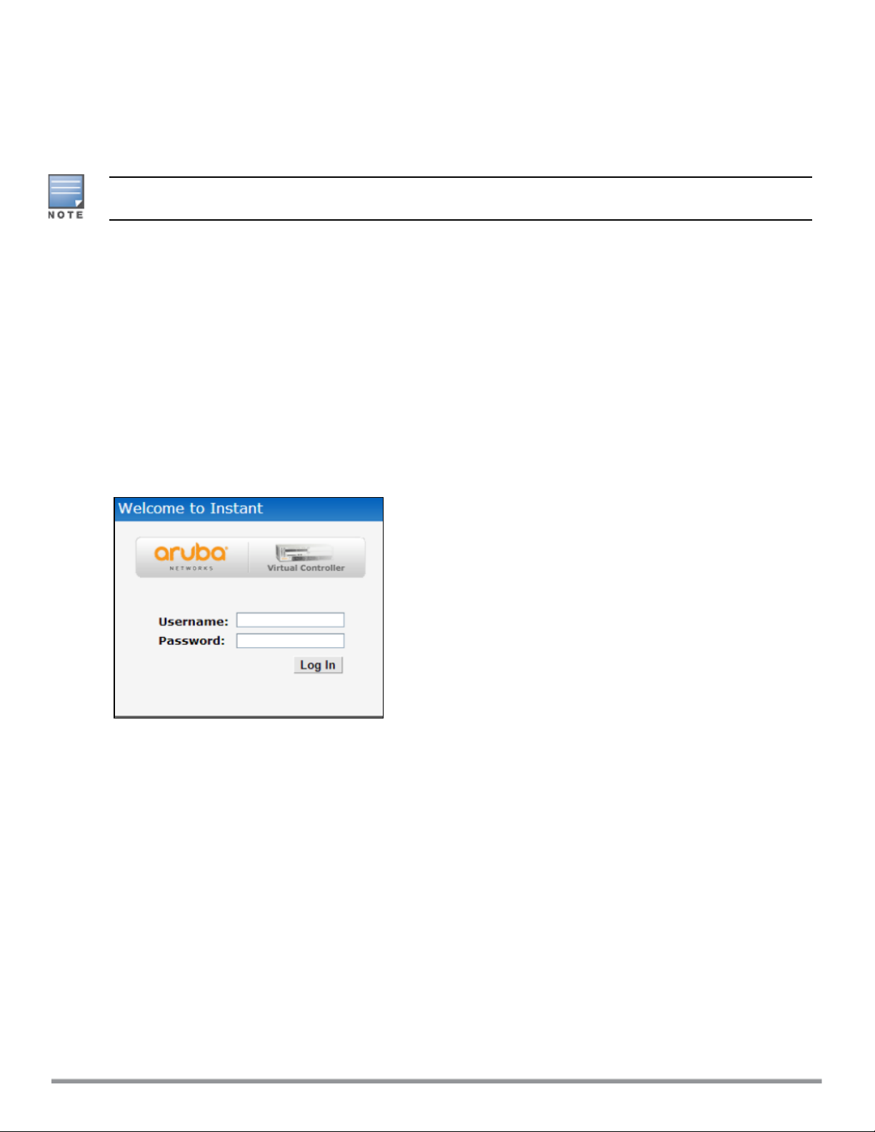
Logging in to the Instant UI
Launch a web browser and enter http://instant.arubanetworks.com. In the login screen, enter the following
credentials:
l Username—admin
l Password—admin
The following figure shows the Login screen:
Figure 1 Login Screen
When you use a provisioning Wi-Fi network to connect to the Internet, all browser requests are directed to the
Instant UI. For example, if you enter www.example.com in the address bar, you are directed to the Instant UI.
You can change the default login credentials after the first login.
Regulatory Domains
The IEEE 802.11/b/g/n Wi-Fi networks operate in the 2.4 GHz spectrum and IEEE 802.11a/n operates in the 5
GHz spectrum. The spectrum is divided into channels. The 2.4 GHz spectrum is divided into 14 overlapping,
staggered 20 MHz wireless carrier channels. These channels are spaced 5 MHz apart. The 5 GHz spectrum is
divided into more channels. The channels that can be used in a particular country vary based on the
regulations of that country.
The initial Wi-Fi setup requires you to specify the country code for the country in which the Instant operates.
This configuration sets the regulatory domain for the radio frequencies that the IAPs use. Within the regulated
transmission spectrum, a high-throughput 802.11ac, 802.11a, 802.11b/g, or 802.11n radio setting can be
configured. The available 20 MHz, 40 MHz, or 80 MHz channels are dependent on the specified country code.
Aruba Instant 6.5.0.0-4.3.0.0 | User Guide Setting up an IAP | 22
You cannot change the country code for the IAPs in the restricted regulatory domains such as US, Japan, and
Israel for most of the IAP models. For IAP-RW variants, you can select from the list of supported regulatory
domains. If the supported country code is not in the list, contact your Aruba Support team to know if the
required country code is supported and obtain the software that supports the required country code.
Improper country code assignments can disrupt wireless transmissions. Most countries impose
penalties and sanctions on operators of wireless networks with devices set to improper country
codes.
To view the country code information, run the show country-codes command.
Specifying Country Code
This procedure is applicable only to the IAP-RW variants. Skip this step if you are installing IAP in the United
States, Japan, or Israel.
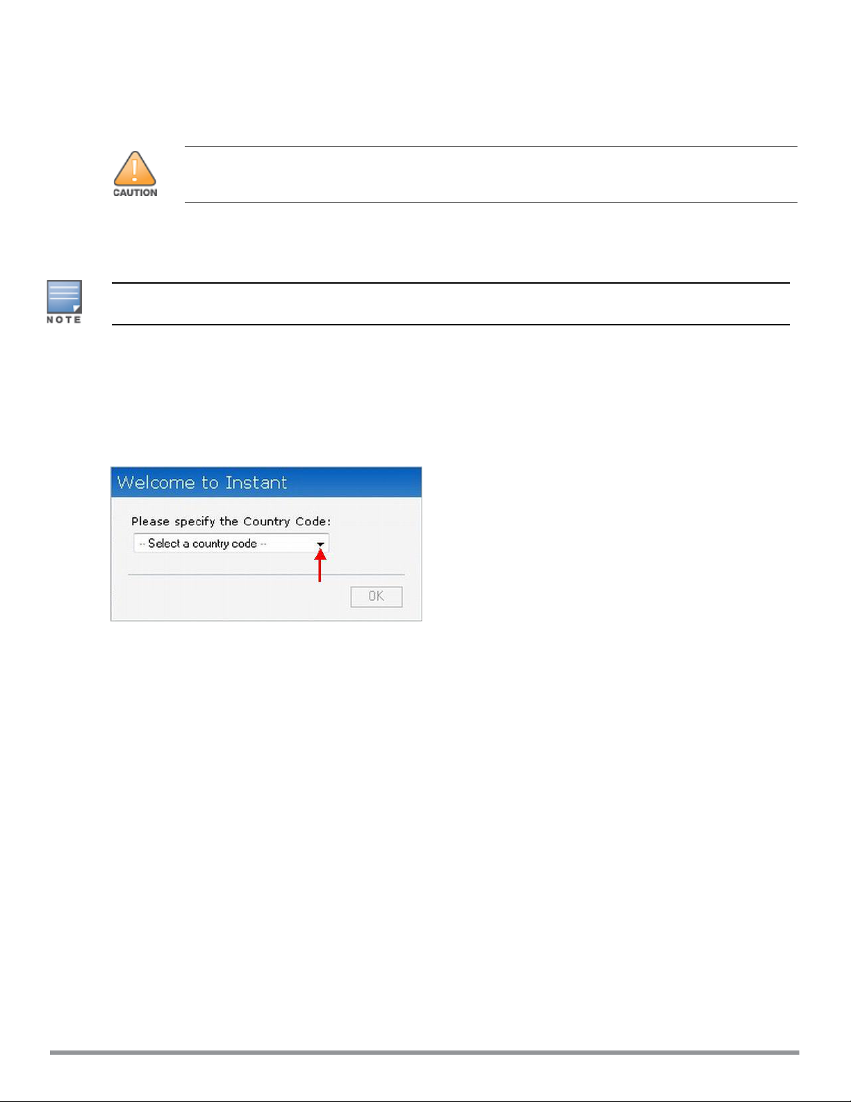
The Country Code window is displayed for the IAP-RW variants when you log in to the IAP UI for the first time.
The Please Specify the Country Code drop-down list displays only the supported country codes. If the IAP
cluster consists of multiple IAP platforms, the country codes supported by the master IAP is displayed for all
other IAPs in the cluster. Select a country code from the list and click OK. The IAP operates in the selected
country code domain.
Figure 2 Specifying a Country Code
.
You can also view the list of supported country codes for the IAP-RW variants using the show country-codes
command.
Accessing the Instant CLI
Instant supports the use of Command Line Interface (CLI) for scripting purposes. When you make
configuration changes on a master IAP in the CLI, all associated IAPs in the cluster inherit these changes and
subsequently update their configurations. By default, you can access the CLI from the serial port or from an
SSH session. You must explicitly enableTelnet access on the IAP to access the CLI through a Telnet session.
For information on enabling SSH and Telnet access to the IAP CLI, see Terminal access on page 64.
Connecting to a CLI Session
On connecting to a CLI session, the system displays its host name followed by the login prompt. Use the
administrator credentials to start a CLI session. For example:
User: admin
If the login is successful, the privileged command mode is enabled and a command prompt is displayed. For
example:
(Instant AP)#
23 | Setting up an IAP Aruba Instant 6.5.0.0-4.3.0.0 | User Guide

The privileged EXEC mode provides access to show, clear, ping, traceroute, and commit commands. The
configuration commands are available in the config mode. To move from Privileged EXEC mode to the
Configuration mode, enter the following command at the command prompt:
(Instant AP)# configure terminal
The configure terminal command allows you to enter the basic configuration mode and the command prompt
is displayed as follows:
(Instant AP)(config)#
The Instant CLI allows CLI scripting in several other subcommand modes to allow the users to configure
individual interfaces, SSIDs, access rules, and security settings.
You can use the question mark (?) to view the commands available in a privileged EXEC mode, configuration
mode, or subcommand mode.
Although automatic completion is supported for some commands such as configure terminal, the
complete exit and end commands must be entered at command prompt.
Applying Configuration Changes
Each command processed by the VC is applied on all the slaves in a cluster. The changes configured in a CLI
session are saved in the CLI context. The CLI does not support the configuration data exceeding the 4K buffer
size in a CLI session. Therefore, Aruba recommends that you configure fewer changes at a time and apply the
changes at regular intervals.
To apply and save the configuration changes at regular intervals, execute the following command in the
privileged EXEC mode:
(Instant AP)# commit apply
To apply the configuration changes to the cluster without saving the configuration, execute the following
command in the privileged EXEC mode:
(Instant AP)# commit apply no-save
To view the changes that are yet to be applied, execute the following command in the privileged EXEC mode:
(Instant AP)# show uncommitted-config
To revert to the earlier configuration, execute the following command in the privileged EXEC mode.
(Instant AP)# commit revert
Example:
To apply and view the configuration changes:
(Instant AP)(config)# rf dot11a-radio-profile
(Instant AP)(RF dot11a Radio Profile)# beacon-interval 200
(Instant AP)(RF dot11a Radio Profile)# no legacy-mode
(Instant AP)(RF dot11a Radio Profile)# dot11h
(Instant AP)(RF dot11a Radio Profile)# interference-immunity 3
(Instant AP)(RF dot11a Radio Profile)# csa-count 2
(Instant AP)(RF dot11a Radio Profile)# spectrum-monitor
(Instant AP)(RF dot11a Radio Profile)# end
(Instant AP)# show uncommitted-config
rf dot11a-radio-profile
beacon-interval 200
no legacy-mode
dot11h
interference-immunity 3
csa-count 2
spectrum-monitor
Aruba Instant 6.5.0.0-4.3.0.0 | User Guide Setting up an IAP | 24

(Instant AP)# commit apply
Using Sequence-Sensitive Commands
The Instant CLI does not support positioning or precedence of sequence-sensitive commands. Therefore,
Aruba recommends that you remove the existing configuration before adding or modifying the configuration
details for sequence-sensitive commands. You can either delete an existing profile or remove a specific
configuration by using the no… commands.
The following table lists the sequence-sensitive commands and the corresponding no commands to remove
the configuration:
Table 8: Sequence-Sensitive Commands
Sequence-Sensitive Command Corresponding no command
opendns <username <password> no opendns
rule <dest> <mask> <match> <protocol> <start-port>
<end-port> {permit | deny | src-nat | dst-nat {<IP-
address> <port> | <port>}}[<option1....option9>]
mgmt-auth-server <auth-profile-name>
set-role <attribute>{{equals| not-equals | startswith | ends-with | contains} <operator> <role> |
value-of}
set-vlan <attribute>{{equals | not-equals | startswith | ends-with | contains} <operator> <VLAN-ID> |
value-of}
auth-server <name> no auth-server <name>
no rule <dest> <mask> <match>
<protocol> <start-port> <end-port>
{permit | deny | src-nat | dst-nat}
no mgmt-auth-server <auth-profilename>
no set-role <attribute>{{equals |
not-equals | starts-with | ends-with
| contains} <operator>| value-of}
no set-role
no set-vlan <attribute>{{equals |
not-equals | starts-with | ends-with
| contains} <operator> | value-of}
no set-vlan
Banner and Loginsession Configuration using CLI
Starting from Instant 6.5.0.0-4.3.0.0, the Banner and Loginsession Configuration feature is introduced in the
IAP, wherein the text banner can be displayed at the login prompt when users are on a management (Telnet or
SSH) session of the CLI, and the management session can remain active even when there is no user activity
involved.
The banner command defines a text banner to be displayed at the login prompt of a CLI. Instant supports up
to 16 lines text, and each line accepts a maximum of 255 characters including spaces.
To configure a banner:
(Instant AP)(config)# banner motd <motd_text>
Example of a text banner configuration:
(Instant AP)(config)# banner motd "######welcome to login instant###########"
(Instant AP)(config)# banner motd "####please start to input admin and password#########"
(Instant AP)(config)# banner motd "###Don't leak the password###"
(Instant AP)(config)# end
(Instant AP)# commit apply
25 | Setting up an IAP Aruba Instant 6.5.0.0-4.3.0.0 | User Guide

To display the banner:
(Instant AP)# show banner
The loginsession command configures the management session (Telnet or SSH) to remain active without any
user activity.
To define a timeout interval:
(Instant AP) (config) #loginsession timeout <val>
<val> can be any number of minutes from 5 to 60, or any number of seconds from 1 to 3600. You can also
specify a timeout value of 0 to disable CLI session timeouts. The users must re-login to the IAP after the session
times out. The session does not time out when the value is set to 0.
Aruba Instant 6.5.0.0-4.3.0.0 | User Guide Setting up an IAP | 26

Chapter 4
Automatic Retrieval of Configuration
This chapter provides the following information:
l Managed Mode Operations on page27
l Prerequisites on page 27
l Configuring Managed Mode Parameters on page 28
l Verifying the Configuration on page 29
Managed Mode Operations
IAPs support managed mode operations to retrieve the configuration file from a server through the File
Transfer Protocol (FTP) or FTP over Secure Sockets Layer (FTPS), and automatically update the IAP
configuration.
The server details for retrieving configuration files are stored in the basic configuration of the IAPs. The basic
configuration of an IAP includes settings specific to an IAP, for example, host name, static IP, and radio
configuration settings. When an IAP boots up, it performs a GET operation to retrieve the configuration (.cfg)
file from the associated server using the specified download method.
After the initial configuration is applied to the IAPs, the configuration can be changed at any point. You can
configure a polling mechanism to fetch the latest configuration by using an FTP or FTPS client periodically. If
the remote configuration is different from the one running on the IAP and if a differencein the configuration
file is detected by the IAP, the new configuration is applied. At any given time, IAPs can fetch only one
configuration file, which may include the configuration details specific to an IAP. For configuring polling
mechanism and downloading configuration files, the users are required to provide credentials (username and
password). However, if automatic mode is enabled, the user credentials required to fetch the configuration file
areautomatically generated. To enable automatic configuration of the IAPs, configure the managed mode
command parameters.
Prerequisites
Perform the following checks before configuring the managed mode command parameters:
l Ensure that the IAP is running Instant 6.2.1.0-3.4 or later versions.
l When the IAPs are in the managed mode, ensure that the IAPs are not managed by AirWave.
Aruba Instant 6.5.0.0-4.3.0.0 | User Guide Automatic Retrieval of Configuration | 27

Configuring Managed Mode Parameters
To enable the automatic configuration, perform the steps described in the following table:
Table 9: Managed Mode Commands
Steps Command
1. Start a CLI session to configure the
managed-mode profile for automatic
configuration.
2. Enable automatic configuration
Or
Specify the user credentials.
3. Specify the configuration file.
4. Specify the configuration file
download method.
5. Specify the name of the server or the
IP address of the server from which
the configuration file must be
downloaded.
(Instant AP)(config)# managed-mode-profile
(Instant AP)(managed-mode-profile)# automatic
Or
(Instant AP)(managed-mode-profile)# username <username>
(Instant AP)(managed-mode-profile)# password <password>
NOTE: If the automatic mode is enabled, the user credentials are
automatically generated based on IAP MAC address.
(Instant AP)(managed-mode-profile)# config-filename
<file_name>
Filename—Indicates filename in the alphanumeric format. Ensure that
configuration file name does not exceed 40 characters.
(Instant AP)(managed-mode-profile)# download-method
<ftp|ftps>
You can use either FTP or FTPS for downloading configuration files.
(Instant AP)(managed-mode-profile)# server <server_name>
28 | Automatic Retrieval of Configuration Aruba Instant 6.5.0.0-4.3.0.0 | User Guide

Table 9: Managed Mode Commands
Steps Command
6. Configure the day and time at which
the IAPs can poll the configuration
files from the server.
7. Configure the time interval in
minutes between two retries, after
which IAPs can retry downloading the
configuration file.
8. Apply the configuration changes.
(Instant AP) (managed-mode-profile)# sync-time day <dd>
hour <hh> min <mm> window <window>
Based on the expected frequency of configuration changes and
maintenance window, you can set the configuration synchronization
timeline.
l day <dd>—Indicates day, for example to configure Sunday as the
day, specify 01. To configure the synchronization period as
everyday, specifiy 00.
l hour <hh>—Indicates hour within the range of 0–23.
l min <mm>—Indicates minutes within the range of 0–59.
l window <hh>—Defines a window for synchronization of the
configuration file. The default value is 3 hours.
(Instant AP)(managed-mode-profile)# retry-poll-period
<seconds>
NOTE: Specify the retry interval in seconds within the range of 5–60
seconds. The default retry interval is 5 seconds.
(Instant AP)(managed-mode-profile)# end
(Instant AP)# commit apply
If you want to apply the configuration immediately and do not want to wait until next configuration retrieval
attempt, execute the following command:
(Instant AP)# managed-mode-sync-server
Example
To configure managed mode profile:
(Instant AP)(config)# managed-mode-profile
(Instant AP)(managed-mode-profile)# username <username>
(Instant AP)(managed-mode-profile)# password <password>
(Instant AP)(managed-mode-profile)# config-filename instant.cfg
(Instant AP)(managed-mode-profile)# download-method ftps
(Instant AP)(managed-mode-profile)# sync-time day 00 hour 03 min 30 window 02
(Instant AP)(managed-mode-profile)# retry-poll-period 10
(Instant AP)(managed-mode-profile)# end
(Instant AP)# commit apply
Verifying the Configuration
To verify if the automatic configuration functions, perform the following checks:
1. Verify the status of configuration by running the following commands at the command prompt:
(Instant AP)# show managed-mode config
(Instant AP)# show managed-mode status
2. Verify the status of download by running the following command at the command prompt:
(Instant AP)# show managed-mode logs
Aruba Instant 6.5.0.0-4.3.0.0 | User Guide Automatic Retrieval of Configuration | 29

If the configuration settings retrieved in the configuration file are incomplete, IAPs reboot with the earlier
configuration.
30 | Automatic Retrieval of Configuration Aruba Instant 6.5.0.0-4.3.0.0 | User Guide

This chapter describes the following Instant UI elements:
l Login Screen on page 31
l Main Window on page 32
Login Screen
The Instant login page allows you to perform the following tasks:
l View Instant Network Connectivity summary
l View the Instant UI in a specific language
l Log in to the Instant UI
Viewing Connectivity Summary
Chapter 5
Instant User Interface
The login page also displays the connectivity status to the Instant network. The users can view a summary that
indicates the status of the Internet availability, uplink, cellular modem and signal strength, VPN, and AirWave
configuration details before logging in to the Instant UI.
The following figure shows the information displayed in the connectivity summary:
Figure 3 Connectivity Summary
Language
The Language drop-down list contains the available languages and allows users to select their preferred
language before logging in to the Instant UI. A default language is selected based on the language preferences
in the client desktop operating system or browser. If Instant cannot detect the language, then English is used
as the default language.
You can also select the required language option from the Languages drop-down list located on the Instant
main window.
Logging into the Instant UI
To log in to the Instant UI, enter the following credentials:
l Username—admin
l Password—admin
The Instant UI main window is displayed.
Aruba Instant 6.5.0.0-4.3.0.0 | User Guide Instant User Interface | 31

When you log in to an IAP with the factory default settings, a popup box displays an option to sign up for the
Aruba cloud solution and enable IAP management through Aruba Central. To sign up for a free 90-day trial of
Central, click here on the Instant main window.
Main Window
On logging in to Instant, the Instant UI Main Window is displayed. The following figure shows the Instant main
window:
Figure 4 Instant Main Window
The main window consists of the following elements:
l Banner
l Search Text Box
l Tabs
l Links
l Views
Banner
The banner is a horizontal gray rectangle that appears on the Instant main window. It displays the company
name, logo, and the VC's name.
Search Text Box
Administrators can search for an IAP, client, or a network in the Search text box. When you type a search text,
the search function suggests matching keywords and allows you to automatically complete the search text
entry.
Tabs
The Instant main window consists of the following tabs:
n Network Tab—Provides information about the network profiles configured in the Instant network.
n Access Points Tab—Provides information about the IAPs configured in the Instant network.
n Clients Tab—Provides information about the clients in the Instant network.
32 | Instant User Interface Aruba Instant 6.5.0.0-4.3.0.0 | User Guide

Each tab appears in a compressed view by default. The number of networks, IAPs, or clients in the network
precedes the coresponding tab names. The individual tabs can be expanded or collapsed by clicking the tabs.
The list items in each tab can be sorted by clicking the triangle icon next to the heading labels.
Network Tab
This tab displays a list of Wi-Fi networks that are configured in the Instant network. The network names are
displayed as links. The expanded view displays the following information about each WLAN SSID:
l Name—Name of the network.
l Clients—Number of clients that are connected to the network.
l Type—Type of network such as Employee, Guest, or Voice.
l Band—Band in which the network is broadcast: 2.4 GHz band, 5 GHz band, or both.
l Authentication Method—Authentication method required to connect to the network.
l Key Management—Authentication key type.
l IP Assignment—Source of IP address for the client.
l Zone—IAP zone configured on the SSID.
To add a wireless network profile, click the New link on the Network tab. To edit, click the edit link that is
displayed on clicking the network name in the Network tab. To delete a network, click the x link.
For more information on the procedure to add or modify a wireless network, see Wireless Network Profiles on
page81.
Access Points Tab
If the Auto-Join Mode feature is enabled, a list of enabled and active IAPs in the Instant network is displayed on
the Access Points tab. The IAP names are displayed as links. If the Auto Join Mode feature is disabled, the
New link is displayed. Click this link to add a new IAP to the network. If an IAP is configured and not active, its
MAC Address is displayed in red.
The expanded view of the Access Points tab displays the following information about each IAP:
l Name—Name of the IAP. If the IAP functions as a master IAP in the network, the asterisk sign "*" is
displayed next to the IAP.
l IP Address—IP address of the IAP.
l Mode—Mode of the IAP.
n Access—In this mode, the IAP serves clients and scans the home channel for spectrum analysis while
monitoring channels for rogue IAPs in the background.
n Monitor—In this mode, the IAP acts as a dedicated Air Monitor (AM), scanning all channels for rogue
IAPs and clients.
l Spectrum—When enabled, the IAP functions as a dedicated full-spectrum RF monitor, scanning all
channels to detect interference from neighboring IAPs or non-Wi-Fi devices such as microwaves and
cordless phones. When Spectrum is enabled, the IAP does not provide access services to clients.
l Clients—Number of clients that are currently associated to the IAP.
l Type—Model number of the IAP.
l Mesh Role—Role of the IAP as a mesh portal or mesh point.
l Zone—IAP zone.
l Serial number—Serial number of the device.
l Channel—Channel on which the IAP is currently broadcast.
l Power (dB)—Maximum transmission Effective Isotropic Radiated Power (EIRP) of the radio.
l Utilization (%)—Percentage of time that the channel is utilized.
Aruba Instant 6.5.0.0-4.3.0.0 | User Guide Instant User Interface | 33

l Noise (dBm)—Noise floor of the channel.
An edit link is displayed on clicking the IAP name. For details on editing IAP settings, see Customizing IAP
Settings on page 68.
Clients Tab
This tab displays a list of clients that areconnected to the Instant network. The client names are displayed as
links. The expanded view displays the following information about each client:
l Name—Username of the client or guest users if available.
l IP Address—IP address of the client.
l MAC Address—MAC address of the client.
l OS—Operating system that runs on the client.
l ESSID—ESSID to which the client is connected.
l Access Point—IAP to which the client is connected.
l Channel—The client operating channel.
l Type—Type of the Wi-Fi client.
l Role—Role assigned to the client.
l Signal—Current signal strength of the client, as detected by the IAP.
l Speed (mbps)—Current speed at which data is transmitted. When the client is associated with an IAP, it
constantly negotiates the speed of data transfer. A value of 0 means that the IAP has not heard from the
client for some time.
Links
The following links allow you to configure various features for the Instant network:
l New Version Available
l System
l RF
l Security
l Maintenance
l More
l Help
l Logout
l Monitoring
l Client Match
l AppRF
l Spectrum
l Alerts
l IDS
l AirGroup
l Configuration
l AirWave Setup
l Pause/Resume
Each of these links is explained in the subsequent sections.
34 | Instant User Interface Aruba Instant 6.5.0.0-4.3.0.0 | User Guide

New Version Available
This link is displayed on the Instant main window only if a new image version is available on the image server
and AirWave is not configured. For more information on the New version available link and its functions, see
Upgrading an IAP on page 348.
System
This link displays the System window. The System window consists of the following tabs:
Use the Show/Hide Advanced option of the System window to view or hide the advanced options.
l General—Allows you to configure, view, or edit the Name, IP address, NTP Server, and other IAP settings
for the VC.
l Admin—Allows you to configure administrator credentials for access to the VC Management UI. You can
also configure AirWave in this tab. For more information on management interface and AirWave
configuration, see Managing IAP Users on page 143 and Managing an IAP from AirWave on page 305,
respectively.
l Uplink—Allows you to view or configure uplink settings. See Uplink Configuration on page 317 for more
information.
l L3 Mobility—Allows you to view or configure the Layer-3 mobility settings. See Configuring L3-Mobility on
page338 for more information.
l Enterprise Domains—Allows you to view or configure the DNS domain names that are valid in the
enterprise network. See Configuring Enterprise Domains on page 196 for more information.
l Monitoring—Allows you to view or configure the following details:
n Syslog—Allows you to view or configure Syslog server details for sending syslog messages to the
external servers. See Configuring a Syslog Server on page 364 for more information.
n TFTP Dump—Allows you to view or configure a Trivial File Tranfer Protocol (TFTP) dump server for core
dump files. See Configuring TFTP Dump Server on page 365 for more information.
n SNMP—Allows you to view or configure Simple Network Management Protocol (SNMP) agent settings.
See Configuring SNMP on page 360 for more information.
l WISPr—Allows you to view or configure the Wireless ISP-roaming (WISPr) settings. See Configuring WISPr
Authentication on page 175 for more information.
l Proxy—Allows you to configure HTTP proxy on an IAP. See Configuring HTTP Proxy on an IAP on page 348
for more information.
l Time Based Services—Allows you to configure a time profile which can be assigned to the
SSIDconfigured on the IAP. See Configuring Time-Based Services on page 221
RF
The RFlink displays a window for configuring Adaptive Radio Management (ARM) and Radio features.
l ARM—Allows you to view or configure channel and power settings for all the IAPs in the network. For
information on ARM configuration, see ARM Overview on page 253.
l Radio—Allows you to view or configure radio settings for 2.4 GHz and the 5 GHz radio profiles. For
information on Radio, see Configuring Radio Settings on page 260.
Aruba Instant 6.5.0.0-4.3.0.0 | User Guide Instant User Interface | 35

Security
The Security link displays a window with the following tabs:
l Authentication Servers—Use this tab to configure an external RADIUS server for a wireless network. For
more information, see Configuring an External Server for Authentication on page 156.
l Users for Internal Server—Use this tab to populate the system’s internal authentication server with
users. This list is used by networks for which per-user authorization is specified using the internal
authentication server of the VC. For more information on users, see Managing IAP Users on page 143.
l Roles —Use this tab to view the roles defined for all the Networks. The Access Rules part allows you to
configure permissions for each role. For more information, see Configuring User Roles on page 199 and
Configuring ACL Rules for Network Services on page 182.
l Blacklisting—Use this tab to blacklist clients. For more information, see Blacklisting Clients on page 176.
l Firewall Settings—Use this tab to enable or disable Application Layer Gateway (ALG) supporting address
and port translation for various protocols and to configure protection against wired attacks. For more
information, see Configuring ALG Protocols on page 188 and Configuring Firewall Settings for Protection
from ARP Attacks on page 189
l Inbound Firewall—Use this tab to enhance the inbound firewall by allowing the configuration of inbound
firewall rules, management subnets, and restricted corporate access through an uplink switch. For more
information, see Managing Inbound Traffic on page 191.
l Walled Garden—Use this tab to allow or prevent access to a selected list of websites. For more
information, see Configuring Walled Garden Access on page 141.
l External Captive Portal—Use this tab to configure external captive portal profiles. For more information,
see Configuring External Captive Portal for a Guest Network on page 129.
l Custom Blocked Page URL—Use this tab to create a list of URLs that can be blocked using an ACL rule.
For more information, see Creating Custom Error Page for Web Access Blocked by AppRF Policies on page
198.
Maintenance
The Maintenance link displays a window that allows you to maintain the Wi-Fi network. The Maintenance
window consists of the following tabs:
l About—Displays the name of the product, build time, IAP model name, the Instant version, website
address of Aruba Networks, and copyright information.
l Configuration—Displays the following details:
n Current Configuration—Displays the current configuration details.
n Clear Configuration—Allows you to clear the current configuration details of the network.
n Backup Configuration—Allows you to back up local configuration details. The backed up configuration
data is saved in the file named instant.cfg.
n Restore Configuration—Allows you to restore the backed up configuration. After restoring the
configuration, the IAP must be rebooted for the changes to take effect.
l Certificates—Displays information about the certificates installed on the IAP. You can also upload new
certificates to the IAP database. For more information, see Uploading Certificates on page 179.
l Firmware—Displays the current firmware version and provides various options to upgrade to a new
firmware version. For more information, see Upgrading an IAP on page 348.
l Reboot—Displays the IAPs in the network and provides an option to reboot the required IAP or all IAPs. For
more information, see Upgrading an IAP on page 348.
36 | Instant User Interface Aruba Instant 6.5.0.0-4.3.0.0 | User Guide

l Convert—Provides an option to convert an IAP to a Mobility Controller managed Remote AP or Campus
AP, or to the default VC mode. For more information, see Converting an IAP to a Remote AP and Campus AP
on page 352.
More
The More link allows you to select the following options:
l VPN
l IDS
l Wired
l Services
l DHCP Server
l Support
VPN
The VPNwindow allows you to define communication settings with an Aruba controller or a third party VPN
concentrator. See VPN Configuration on page 228 for more information. The following figure shows an
example of the IPsec configuration options available in the VPN window:
Figure 5 VPN Window for IPsec Configuration
IDS
The IDSwindow allows you to configure wireless intrusion detection and protection levels. The following
figures show the IDS window:
Aruba Instant 6.5.0.0-4.3.0.0 | User Guide Instant User Interface | 37

Figure 6 IDS Window: Intrusion Detection
Figure 7 IDS Window: Intrusion Protection
For more information on wireless intrusion detection and protection, see Detecting and Classifying Rogue IAPs
on page 327.
38 | Instant User Interface Aruba Instant 6.5.0.0-4.3.0.0 | User Guide

Wired
The Wired window allows you to configure a wired network profile. See Wired Profiles on page 108 for more
information. The following figure shows the Wired window:
Figure 8 Wired Window
Services
The Services window allows you to configure services such as AirGroup, Real Time Location System (RTLS), and
OpenDNS. The Services window consists of the following tabs:
l AirGroup—Allows you to configure the AirGroup and AirGroup services. For more information, see
Configuring AirGroup on page 282.
l RTLS—Allows you to integrate AMP or third-party RTLS such as Aeroscout Real Time Location Server with
Instant. For more information, see Configuring an IAP for RTLSSupport on page 291.
The RTLS tab also allows you to integrate IAP with the Analytics and Location Engine (ALE). For more
information about configuring an IAP for ALE integration, see Configuring an IAP for Analytics and Location
Engine Support on page 292.
l OpenDNS—Allows you to configure support for OpenDNS business solutions, which require an OpenDNS
(www.opendns.com) account. The OpenDNS credentials are used by Instant and AirWave to filter content
at the enterprise level. For more information, see Configuring OpenDNS Credentials on page 294.
l CALEA—Allows you configure support for Communications Assistance for Law Enforcement Act (CALEA)
server integration, thereby ensuring compliance with Lawful Intercept and CALEA specifications. For more
information, see CALEA Integration and Lawful Intercept Compliance on page 299.
l Network Integration—Allows you to configure an IAP for integration with Palo Alto Networks (PAN)
Firewall and XML API server. For more information on IAP integration with PAN, see Integrating an IAP with
Palo Alto Networks Firewall on page 295and Integrating an IAP with an XMLAPIInterface on page 297.
Aruba Instant 6.5.0.0-4.3.0.0 | User Guide Instant User Interface | 39

The following figure shows the default view of the Services window:
Figure 9 Services Window: Default View
DHCP Server
The DHCP Servers window allows you to configure various DHCP modes. The following figure shows the
options available in the DHCP Servers window:
Figure 10 DHCP Servers Window
For more information, see DHCP Configuration on page 211.
Support
The Support link consists of the following details:
l Command—Allows you to select a support command for execution.
l Target—Displays a list of IAPs in the network.
l Run—Allows you to execute the selected command for a specific IAP or all IAPs and view logs.
40 | Instant User Interface Aruba Instant 6.5.0.0-4.3.0.0 | User Guide

l Auto Run—Allows you to configure a schedule for automatic execution of a support command for a
specific IAP or all IAPs.
l Filter—Allows you to filter the contents of a command output.
l Clear—Clears the command output that is displayed after a command is executed.
l Save—Allows you to save the support command logs as an HTML or text file.
For more information on support commands, see Running Debug Commands on page 366.
Help
The Help link allows you to view a short description or definition of the selected terms in the UI windows or the
dialog boxes.
To activate the context-sensitive help:
1. Click the Help link available above the Search bar on the Instant main window.
2. Click any text or term displayed in green italics to view its description or definition.
3. To disable the help mode, click Done.
Logout
The Logout link allows you to log out of the Instant UI.
Monitoring
The Monitoring link displays the Monitoring pane for the Instant network. Use the down arrow located
to the right side of these links to compress or expand the Monitoring pane.
The Monitoring pane consists of the following sections:
l Info
l RF Dashboard
l RF Trends
l Usage Trends
l Mobility Trail
Info
The Info section displays the configuration information of the VC by default. On selecting the Network View
tab, the monitoring pane displays configuration information of the selected network. Similarly, in the Access
Point or the Client view, this section displays the configuration information of the selected IAP or the client.
Aruba Instant 6.5.0.0-4.3.0.0 | User Guide Instant User Interface | 41

Table 10: Contents of the Info Section in the Instant Main Window
Name Description
Info section in the Virtual
Controller view
The Info section in the Virtual Controller view displays the following information:
l Name—Displays the VC name.
l Country Code—Displays the Country in which the VC is operating.
l Virtual Controller IP address—Displays the IP address of the VC.
l VC DNS—Displays the DNS IP address configured for the VC.
l Management—Indicates if the IAP is managed locally or through AirWave or
Aruba Central.
l Master—Displays the IP address of the IAP acting as VC.
l OpenDNS Status—Displays the OpenDNS status. If the OpenDNS status
indicates Not Connected, ensure that the network connection is up and
appropriate credentials are configured for OpenDNS.
l MAS integration—Displays the status of the Mobility Access Switch (MAS)
integration feature.
l Uplink type—Displays the type of uplink configured on the IAP, for example,
Ethernet or 3G.
l Uplink status—Indicates the uplink status.
l Blacklisted clients—Displays the number of blacklisted clients.
l Internal RADIUS Users—Displays the number of internal RADIUSusers.
l Internal Guest Users—Displays the number of internal guest users.
l Internal User Open Slots—Displays the available slots for user configuration
as supported by the IAP model.
Info section in the Network
view
Info section in the Access
Point view
The Info section in the Network view displays the following information:
l Name—Displays the name of the network.
l Status—Displays the status of the network.
l Type—Displays the type of network, for example, Employee, Guest, or Voice.
l VLAN—Displays VLAN details.
l IP Assignment—Indicates if the IAP clients are assigned IP address from the
network that the VC is connected to, or from an internal autogenerated IP
scope from the VC.
l Access—Indicates the level of access control configured for the network.
l WMM DSCP—Displays Wi-Fi Multemedia (WMM)DSCP mapping details.
l Security level—Indicates the type of user authentication and data encryption
configured for the network.
The info section for WLAN SSIDs also indicates status of captive portal and CALEA
ACLs and provides a link to upload certificates for the internal server. For more
information, see Uploading Certificates on page 179.
The Info section in the Access Point view displays the following information:
l Name—Displays the name of the selected IAP.
l IP Address—Displays the IP address of the IAP.
42 | Instant User Interface Aruba Instant 6.5.0.0-4.3.0.0 | User Guide

Table 10: Contents of the Info Section in the Instant Main Window
Name Description
l Mode—Displays the mode in which the IAP is configured to operate.
l Spectrum—Displays the status of the spectrum monitor.
l Clients—Number of clients associated with the IAP.
l Type—Displays the model number of the IAP.
l Zone—Displays IAP zone details.
l CPU Utilization—Displays the CPU utilization in percentage.
l Memory Free—Displays the memory availability of the IAP in MB.
l Serial number—Displays the serial number of the IAP.
l MAC—Displays the MAC address.
l From Port—Displays the port from where the slave IAP is learned in hierarchy
mode.
Info section in the Client view The Info section in the Client view displays the following information:
l Name—Displays the name of the client.
l IP Address—Displays the IP address of the client.
l MAC Address—Displays MAC address of the client.
l OS—Displays the operating system that is running on the client.
l ESSID—Indicates the network to which the client is connected.
l Access Point—Indicates the IAP to which the client is connected.
l Channel—Indicates the channel that is currently used by the client.
l Type—Displays the channel type on which the client is broadcasting.
l Role—Displays the role assigned to the client.
RF Dashboard
The RF Dashboard section lists the IAPs that exceed the utilization, noise, or error threshold. It also shows the
clients with low speed or signal strength in the network and the RF information for the IAP to which the client is
connected.
The IAP names are displayed as links. When an IAP is clicked, the IAP configuration information is displayed in
the Info section and the RF Dashboard section is displayed on the Instant main window.
The following figure shows an example of the RF dashboard with Utilization, Band frames, Noise Floor, and
Errors details:
Figure 11 RF Dashboard in the Monitoring Pane
The following table describes the icons available on the RF Dashboard pane:
Aruba Instant 6.5.0.0-4.3.0.0 | User Guide Instant User Interface | 43

Table 11: RF Dashboard Icons
Icon
number
Name Description
1 Signal Displays the signal strength of the client. Signal strength is measured in decibels.
Depending on the signal strength of the client, the color of the lines on the Signal icon
changes in the following order:
l Green—Signal strength is more than 20 dB.
l Orange—Signal strength is between 15 dB and 20 dB.
l Red—Signal strength is less than 15 dB.
To view the signal graph for a client, click the signal icon next to the client in the Signal
column.
2 Speed Displays the data transfer speed of the client. Depending on the data transfer speed of
the client, the color of the Speed icon changes in the following order:
l Green—Data transfer speed is more than 50% of the maximum speed supported by
the client.
l Orange—Data transfer speed is between 25% and 50% of the maximum speed
supported by the client.
l Red—Data transfer speed is less than 25% of the maximum speed supported by the
client.
To view the data transfer speed graph of a client, click the speed icon corresponding to
the client name in the Speed column.
3 Utilization Displays the radio utilization rate of the IAPs. Depending on the percentage of
utilization, the color of the lines on the Utilization icon changes in the following order:
l Green—Utilization is less than 50%.
l Orange—Utilization is between 50% and 75%.
l Red—Utilization is more than 75%.
To view the utilization graph of an IAP, click the Utilization icon next to the IAP in the
Utilization column.
44 | Instant User Interface Aruba Instant 6.5.0.0-4.3.0.0 | User Guide

Table 11: RF Dashboard Icons
Icon
number
Name Description
4 Noise Displays the noise floor details for the IAPs. Noise is measured in decibels/meter.
Depending on the noise floor, the color of the lines on the Noise icon changes in the
following order:
l Green—Noise floor is more than -87 dBm.
l Orange—Noise floor is between -80 dBm and -87 dBm.
l Red—Noise floor is less than -80 dBm.
To view the noise floor graph of an IAP, click the Noise icon next to the IAP in the Noise
column.
5 Errors Displays the errors for the IAPs. Depending on the errors, color of the lines on the
Errors icon changes in the following order:
l Green—Errors are less than 5000 frames per second.
l Orange—Errors are between 5000 and 10,000 frames per second.
l Red—Errors are more than 10000 frames per second.
To view the errors graph of an IAP, click the Errors icon next to the IAP in the Errors
column.
RF Trends
The RF Trends section displays the following graphs for the selected IAP and the client. To view the details on
the graphs, click the graphs and hover the mouse on a data point:
Figure 12 RF Trends for Access Point
Figure 13 RF Trends for Clients
Aruba Instant 6.5.0.0-4.3.0.0 | User Guide Instant User Interface | 45

The following table describes the RF trends graphs available in the Client view:
Table 12: Client View—RF Trends Graphs and Monitoring Procedures
Graph
Name
Description Monitoring Procedure
Signal The Signal graph shows the signal
strength of the client for the last 15
minutes. It is measured in decibels.
To see an enlarged view, click the graph.
The enlarged view provides Last,
Minimum, Maximum, and Average signal
statistics of the client for the last 15
minutes.
To see the exact signal strength at a
particular time, move the cursor over the
graph line.
Frames The Frames graph shows the In and Out
frame rate per second of the client for the
last 15 minutes. It also shows data for the
Retry In and Retry Out frames.
l Outgoing frames—Outgoing frame
traffic is displayed in green. It is shown
above the median line.
l Incoming frames—Incoming frame
traffic is displayed in blue. It is shown
below the median line.
l Retry Out—Retries for the outgoing
frames are displayed above the
median line in black .
l Retry In—Retries for the incoming
frames are displayed below the
median line in red.
To see an enlarged view, click the graph.
The enlarged view provides Last,
Minimum, Maximum, and Average
statistics for the In, Out, Retries In, and
Retries Out frames.
To see the exact frames at a particular
time, move the cursor over the graph line.
To monitor the signal strength of the selected client
for the last 15 minutes:
1. Log in to the Instant UI. The Virtual Controller view
is displayed. This is the default view.
2. On the Clients tab, click the IP address of the
client for which you want to monitor the signal
strength.
3. Study the Signal graph in the RF Trends pane. For
example, the graph shows that signal strength for
the client is 54.0 dB at 12:23 hours.
To monitor the In and Out frame rate per second and
retry frames for the In and Out traffic, for the last 15
minutes:
1. Log in to the Instant UI. The Virtual Controller view
is displayed. This is the default view.
2. On the Clients tab, click the IP address of the
client for which you want to monitor the frames.
3. Study the Frames graph in the RF Trends pane.
For example, the graph shows 4.0 frames per
second for the client at 12:27 hours.
Speed The Speed graph shows the data transfer
speed for the client. Data transfer is
measured in Mbps.
To see an enlarged view, click the graph.
The enlarged view shows Last, Minimum,
Maximum, and Average statistics of the
client for the last 15 minutes.
To monitor the speed for the client for the last 15
minutes:
1. Log in to the Instant UI. The Virtual Controller view
is displayed. This is the default view.
2. On the Clients tab, click the IP address of the
client for which you want to monitor the speed.
3. Study the Speed graph in the RF Trends pane. For
example, the graph shows that the data transfer
46 | Instant User Interface Aruba Instant 6.5.0.0-4.3.0.0 | User Guide

Table 12: Client View—RF Trends Graphs and Monitoring Procedures
Graph
Name
Throughput The Throughput Graph shows the
Description Monitoring Procedure
To see the exact speed at a particular
time, move the cursor over the graph line.
throughput of the selected client for the
last 15 minutes.
l Outgoing traffic—Throughput for the
outgoing traffic is displayed in green.
It is shown above the median line.
l Incoming traffic—Throughput for the
incoming traffic is displayed in blue. It
is shown below the median line.
To see an enlarged view, click the graph.
The enlarged view shows Last, Minimum,
Maximum, and Average statistics for the
incoming and outgoing traffic throughput
of the client for the last 15 minutes.
To see the exact throughput at a
particular time, move the cursor over the
graph line.
speed at 12:26 hours is 240 Mbps.
To monitor the errors for the client for the last 15
minutes:
1. Log in to the Instant UI. The Virtual Controller view
is displayed. This is the default view.
2. In the Clients tab, click the IP address of the client
for which you want to monitor the throughput.
3. Study the Throughput graph in the RF Trends
pane. For example, the graph shows 1.0 Kbps
outgoing traffic throughput for the client at 12:30
hours.
Usage Trends
The Usage Trends section displays the following graphs:
l Clients—In the default view, the Clients graph displays the number of clients that were associated with the
VC in the last 15 minutes. In Network view or the Access Point view, this graph displays the number of
clients that were associated with the selected network or IAP in the last 15 minutes.
l Throughput—In the default view, the Throughput graph displays the incoming and outgoing throughput
traffic for the VC in the last 15 minutes. In the Network view or the Access Point view, this graph displays
the incoming and outgoing throughput traffic for the selected network or IAP in the last 15 minutes.
Figure 14 Usage Trends Graphs in the Default View
Aruba Instant 6.5.0.0-4.3.0.0 | User Guide Instant User Interface | 47

The following table describes the graphs displayed in the Network view:
Table 13: Network View—Graphs and Monitoring Procedures
Graph Name Description Monitoring Procedure
Clients The Clients graph shows the number of clients
associated with the network for the last 15
minutes.
To see an enlarged view, click the graph.
l The enlarged view provides Last, Minimum,
Maximum, and Average statistics for the
number of clients associated with the VC for
the last 15 minutes.
l To see the exact number of clients in the
Instant network at a particular time, move
the cursor over the graph line.
Throughput The Throughput graph shows the throughput of
the selected network for the last 15 minutes.
l Outgoing traffic—Throughput for the
outgoing traffic is displayed in green.
Outgoing traffic is shown above the median
line.
l Incoming traffic—Throughput for the
incoming traffic is displayed in blue.
Incoming traffic is shown below the median
line.
To see an enlarged view, click the graph.
l The enlarged view provides Last, Minimum,
Maximum, and Average statistics for the
incoming and outgoing traffic throughput of
the network for the last 15 minutes.
To see the exact throughput of the selected
network at a particular time, move the cursor
over the graph line.
To check the number of clients associated
with the network for the last 15 minutes:
1. Log in to the Instant UI. The Virtual
Controller view is displayed. This is the
default view.
2. On the Network tab, click the network
for which you want to check the client
association.
3. Study the Clients graph in the Usage
Trends pane. For example, the graph
shows that one client is associated with
the selected network at 12:00 hours.
To check the throughput of the selected
network for the last 15 minutes,
1. Log in to the Instant UI. The Virtual
Controller view is displayed. This is the
default view.
2. On the Network tab, click the network
for which you want to check the client
association.
3. Study the Throughput graph in the
Usage Trends pane. For example, the
graph shows 22.0 Kbps incoming traffic
throughput for the selected network at
12:03 hours.
48 | Instant User Interface Aruba Instant 6.5.0.0-4.3.0.0 | User Guide

The following table describes the graphs displayed in the Access Point view:
Table 14: Access Point View—Usage Trends and Monitoring Procedures
Graph Name IAP Description Monitoring Procedure
Neighboring
IAPs
The Neighboring IAPs graph shows the
number of IAPs detected by the selected
IAP:
l Valid IAPs: An IAP that is part of the
enterprise providing WLAN service.
l Interfering IAPs: An IAP that is seen in
the RF environment but is not
connected to the network.
l Rogue IAPs: An unauthorized IAP that
is plugged into the wired side of the
network.
To see the number of different types of
neighboring IAPs for the last 15 minutes,
move the cursor over the respective
graph lines.
CPU Utilization The CPU Utilization graph displays the
utilization of CPU for the selected IAP.
To see the CPU utilization of the IAP,
move the cursor over the graph line.
To check the neighboring IAPs detected by the IAP
for the last 15 minutes:
1. Log in to the Instant UI. The Virtual Controller
view is displayed. This is the default view.
2. On the Access Points tab, click the IAP for which
you want to monitor the client association.
3. Study the Neighboring IAPs graph in the
Overview section. For example, the graph shows
that 148 interfering IAPs are detected by the IAP
at 12:04 hours.
To check the CPU utilization of the IAP for the last 15
minutes:
1. Log in to the Instant UI. The Virtual Controller
view is displayed. This is the default view.
2. On the Access Points tab, click the IAP for which
you want to monitor the client association.
3. Study the CPU Utilization graph in the Overview
pane. For example, the graph shows that the CPU
utilization of the IAP is 30% at 12:09 hours.
Neighboring
Clients
Memory free
(MB)
The Neighboring Clients graph shows the
number of clients not connected to the
selected IAP, but heard by it.
l Any client that successfully
authenticates with a valid IAP and
passes encrypted traffic is classified
as a valid client.
l Interfering: A client associated to any
IAP and is not valid is classified as an
interfering client.
To see the number of different types of
neighboring clients for the last 15
minutes, move the cursor over the
respective graph lines.
The Memory free graph displays the
memory availability of the IAP in MB.
To see the free memory of the IAP, move
the cursor over the graph line.
To check the neighboring clients detected by the IAP
for the last 15 minutes,
1. Log in to the Instant UI. The Virtual Controller
view is displayed. This is the default view.
2. On the Access Points tab, click the IAP for which
you want to monitor the client association.
3. Study the Neighboring Clients graph in the
Overview pane. For example, the graph shows
that 20 interfering clients were detected by the
IAP at 12:15 hours.
To check the free memory of the IAP for the last 15
minutes:
1. Log in to the Instant UI. The Virtual Controller
view is displayed. This is the default view.
Aruba Instant 6.5.0.0-4.3.0.0 | User Guide Instant User Interface | 49

Table 14: Access Point View—Usage Trends and Monitoring Procedures
Graph Name IAP Description Monitoring Procedure
2. On the Access Points tab, click the IAP for which
you want to monitor the client association.
3. Study the Memory free graph in the Overview
pane. For example, the graph shows that the free
memory of the IAP is 64 MB at 12:13 hours.
Clients The Clients graph shows the number of
clients associated with the selected IAP
for the last 15 minutes.
To see an enlarged view, click the graph.
The enlarged view provides Last,
Minimum, Maximum, and Average
statistics for the number of clients
associated with the IAP for the last 15
minutes.
To see the exact number of clients
associated with the selected IAP at a
particular time, move the cursor over the
graph line.
Throughput The Throughput graph shows the
throughput for the selected IAP for the
last 15 minutes.
l Outgoing traffic—Throughput for the
outgoing traffic is displayed in green.
It is shown above the median line.
l Incoming traffic—Throughput for the
incoming traffic is displayed in blue. It
is shown below the median line.
To see an enlarged view, click the graph.
l The enlarged view provides Last,
Minimum, Maximum, and Average
statistics for the incoming and
outgoing traffic throughput of the IAP
for the last 15 minutes.
To see the exact throughput of the
selected IAP at a particular time, move
the cursor over the graph line.
To check the number of clients associated with the
IAP for the last 15 minutes:
1. Log in to the Instant UI. The Virtual Controller
view is displayed. This is the default view.
2. On the Access Points tab, click the IAP for which
you want to monitor the client association.
3. Study the Clients graph. For example, the graph
shows that six clients are associated with the IAP
at 12:11 hours.
To check the throughput of the selected IAP for the
last 15 minutes:
1. Log in to the Instant UI. The Virtual Controller
view is displayed. This is the default view.
2. On the Access Points tab, click the IAP for which
you want to monitor the throughput.
3. Study the Throughput graph. For example, the
graph shows 44.03 Kbps incoming traffic
throughput at 12:08 hours.
Mobility Trail
The Mobility Trail section displays the following mobility trail information for the selected client:
l Association Time—The time at which the selected client was associated with a particular IAP.
The Instant UI shows the client and IAP association over the last 15 minutes.
l Access Point—The IAP name with which the client was associated.
Mobility information about the client is reset each time it roams from one IAP to another.
50 | Instant User Interface Aruba Instant 6.5.0.0-4.3.0.0 | User Guide

Client Match
If Client Match is enabled, the Client Match link provides a graphical representation of radio map view of an
IAP and the client distribution on an IAP radio.
On clicking an access point in the Access Points tab and the Client Match link, a stations map view is
displayed and a graph is drawn with real-time data points for the IAPradio. If the IAP supports dual-band, you
can togglebetween 2.4 GHz and 5 GHz links in the Client Match graph area to view the data. When you hover
the mouse on the graph, details such as RSSI, Client Match status, and the client distribution on channels are
displayed.
The following figure shows the client distribution details for an IAP radio.
Figure 15 Client Distribution on IAP Radio
On clicking a client in the Clients tab and the Client Match link, a graph is drawn with real-time data points for
an IAP radio map. When you hover the mouse on the graph, details such as RSSI, channel utilization details, and
client count on each channel are displayed.
The following figure shows the client view heat map for an IAP radio:
Figure 16 Channel Availability Map for Clients
AppRF
The AppRF link displays the application traffic summary for IAPs and client devices. The AppRF link in the
activity panel is displayed only if AppRF visibility is enabled in the System window. For more information on
application visibility and AppRF charts, see Application Visibility on page 265.
Spectrum
The spectrum link (in Access Point view) displays the spectrum data that is collected by a hybrid IAP or by an
IAP that has enabled spectrum monitor. The spectrum data is not reported to the VC.
The spectrum link displays the following:
l Device list—The device list display consists of a device summary table and channel information for active
non Wi-Fi devices currently seen by a spectrum monitor or a hybrid IAP radio.
l Channel Utilization and Monitoring—This chart provides an overview of channel quality across the
spectrum. It shows channel utilization information such as channel quality, availability, and utilization
Aruba Instant 6.5.0.0-4.3.0.0 | User Guide Instant User Interface | 51

metrics as seen by a spectrum monitor for the 2.4 GHz and 5 GHz radio bands. The first bar for each
channel represents the percentage of airtime used by non-Wi-Fi interference and Wi-Fi devices. The second
bar indicates the channel quality. A higher percentage value indicates better quality.
l Channel Details—When you move your mouse over a channel, the channel details or the summary of the
2.4 GHz and 5 GHz channels as detected by a spectrum monitor are displayed. You can view the aggregate
data for each channel seen by the spectrum monitor radio, including the maximum IAP power, interference,
and the Signal-to-Noise-plus-Interference Ratio (SNIR). Spectrum monitors display spectrum analysis data
seen on all channels in the selected band, and hybrid IAPs display data from the singlechannel that they are
monitoring.
For more information on spectrum monitoring, see Spectrum Monitor on page 340.
Alerts
Alerts are generated when a user encounters problems while accessing or connecting to a network. The alerts
that are generated can be categorized as follows:
l 802.11-related association and authentication failure alerts
l 802.1X-related mode and key mismatch, server, and client time-out failure alerts
l IP-address-related failures—Static IP address or DHCP-related alerts.
The following figure shows the contents of details displayed on clicking the Alerts link:
Figure 17 Alerts Link
The Alerts link displays the following types of alerts:
l Client Alerts
l Active Faults
l Fault History
52 | Instant User Interface Aruba Instant 6.5.0.0-4.3.0.0 | User Guide

Table 15: Types of Alerts
Type of
Alert
Description Information Displayed
Client Alerts The alert type, Client Alerts,
occur when clients are
connected to the Instant
network.
Active Faults The Active Faults alerts occur
in the event of a system fault.
Fault History
The Fault History alerts display
the historic system faults.
The alert type, Client Alert displays the following
information:
l Timestamp—Displays the time at which the client alert
was recorded.
l MAC address—Displays the MAC address of the client
that caused the alert.
l Description—Provides a short description of the alert.
l Access Points—Displays the IP address of the IAP to
which the client is connected.
l Details—Provides complete details of the alert.
The Active Faults alerts consists of the following
information:
l Time—Displays the system time when an event occurs.
l Number—Indicates the number of sequence.
l Description—Displays the event details.
The Fault History alert displays the following information:
l Time—Displays the system time when an event occurs.
l Number—Indicates the number of sequence.
l Cleared by—Displays the module which cleared this fault.
l Description—Displays the event details.
The following figures show the client alerts, active faults, and fault history:
Figure 18 Client Alerts
Aruba Instant 6.5.0.0-4.3.0.0 | User Guide Instant User Interface | 53

Figure 19 Active Faults
Figure 20 Fault History
The following table displays a list of alerts that are generated in the IAP network:
Table 16: Alerts List
Description
Code
100101 Internal error
100102 Unknown SSID in association
100103 Mismatched
Description Details Corrective Actions
Contact the Aruba customer
support team.
Identify the client and check its WiFi driver and manager software.
Ascertain the correct
authentication or encryption
settings and try to associate again.
request
authentication/encryption
setting
The IAP has encountered an
internal error for this client.
The IAP cannot allow this
client to associate because
the association request
received contains an
unknown SSID.
The IAP cannot allow this
client to associate because
its authentication or
encryption settings do not
match AP's configuration.
54 | Instant User Interface Aruba Instant 6.5.0.0-4.3.0.0 | User Guide

Table 16: Alerts List
Description
Code
100104 Unsupported 802.11 rate The IAP cannot allow this
100105 Maximum capacity reached
100206 Invalid MAC Address The IAP cannot authenticate
100307 Client blocked due to
Description Details Corrective Actions
client to associate because
it does not support the
802.11 rate requested by
this client.
The IAP has reached
on IAP
repeated authentication
failures
maximum capacity and
cannot accommodate any
more clients.
this client because its MAC
address is not valid.
The IAP is temporarily
blocking the 802.1X
authentication request from
this client because the
credentials provided have
been rejected by the
RADIUS server too many
times.
Check the configuration on the IAP
to see if the desired rate can be
supported; if not, consider
replacing the IAP with another
model that can support the rate.
Consider expanding capacity by
installing additional IAPs or
balance load by relocating IAPs.
This condition may be indicative of
a misbehaving client. Try to locate
the client device and check its
hardware and software.
Identify the client and check its
802.1X credentials.
100308 RADIUS server connection
failure
100309 RADIUS server
authentication failure
The IAP cannot authenticate
this client using 802.1X
because the RADIUS server
did not respond to the
authentication request. If
the IAP is using the internal
RADIUS server, it is
recommend to check the
related configuration as well
as the installed certificate
and passphrase.
The IAP cannot authenticate
this client using 802.1X,
because the RADIUS server
rejected the authentication
credentials (for example,
password) provided by the
client.
If the IAP is using the internal
RADIUS server, Aruba
recommends checking the related
configuration as well as the
installed certificate and
passphrase.
If the IAP is using an external
RADIUS server, check if there are
any issues with the RADIUS server
and try connecting again.
Ascertain the correct
authentication credentials and log
in again.
Aruba Instant 6.5.0.0-4.3.0.0 | User Guide Instant User Interface | 55

Table 16: Alerts List
Description
Code
100410 Integrity check failure in
Description Details Corrective Actions
The IAP cannot receive data
encrypted message
from this client because the
integrity check of the
received message (MIC) has
failed. Recommend
checking the encryption
setting on the client and on
the IAP.
100511 DHCP request timed out
This client did not receive a
response to its DHCP
request in time.
Recommend checking the
status of the DHCP server in
the network.
101012 Wrong Client VLAN VLAN mismatch between
the IAP and the upstream
device. Upstream device
can be upstream switch or
RADIUS server.
Check the encryption setting on
the client and on the IAP.
Check the status of the DHCP
server in the network.
IDS
The IDSlink displays a list of foreign IAPs and foreign clients that are detected in the network. It consists of the
following sections:
l Foreign Access Points Detected—Lists the IAPs that are not controlled by the VC. The following
information is displayed for each foreign IAP:
n MAC address—Displays the MAC address of the foreign IAP.
n Network—Displays the nameof the network to which the foreign IAP is connected.
n Classification—Displays the classification of the foreign IAP, for example, Interfering IAP or Rogue IAP.
n Channel—Displays the channel in which the foreign IAP is operating.
n Type—Displays the Wi-Fi type of the foreign IAP.
n Last seen—Displays the time when the foreign IAP was last detected in the network.
n Where—Provides information about the IAP that detected the foreign IAP. Click the push pin icon to
view the information.
l Foreign Clients Detected— Lists the clients that are not controlled by the VC. The following information
is displayed for each foreign client:
n MAC address—Displays the MAC address of the foreign client.
n Network—Displays the nameof the network to which the foreign client is connected.
n Classification—Displays the classification of the foreign client: Interfering client.
n Channel—Displays the channel in which the foreign client is operating.
n Type—Displays the Wi-Fi type of the foreign client.
n Last seen—Displays the time when the foreign client was last detected in the network.
56 | Instant User Interface Aruba Instant 6.5.0.0-4.3.0.0 | User Guide

n Where—Provides information about the IAP that detected the foreign client. Click the Push Pin icon to
view the information.
The following figure shows an example for the intrusion detection log:
Figure 21 Intrusion Detection
For more information on the intrusion detection feature, see Intrusion Detection on page 327.
AirGroup
This AirGroup link provides an overall view of your AirGroup configuration. Click each parameter to view or
edit the settings.
l MAC—Displays the MAC address of the AirGroup servers.
l IP—Displays the IP address of the AirGroup servers.
l Host Name—Displays the machine name or host name of the AirGroup servers.
l Service— Displays the type of services such as AirPlay or AirPrint.
l VLAN—Displays VLANdetails of the AirGroup servers.
l Wired/Wireless—Displays if the AirGroup server is connected through a wired or wireless interface.
l Role—Displays the user role if the server is connected through 802.1X authentication. If the server is
connected through Phase-Shift Keying (PSK) or open authentication, this parameter is blank.
l Group—Displays the group.
l CPPM—By clicking this, you get details of the registered rules in ClearPass Policy Manager (CPPM) for this
server.
l MDNS Cache—By clicking this, you receive MDNS record details of a particular server.
The following figure shows the AirGroup server details available on clicking the AirGroup link:
Figure 22 AirGroup Link
Configuration
The Configuration link provides an overall view of your VC, IAPs, and WLAN SSIDconfiguration. The following
figure shows the VC configuration details displayed on clicking the Configuration link.
Aruba Instant 6.5.0.0-4.3.0.0 | User Guide Instant User Interface | 57

Figure 23 Configuration Link
AirWave Setup
AirWave is a solution for managing rapidly changing wireless networks. When enabled, AirWave allows you to
manage the Instant network. For more information on AirWave, see Managing an IAP from AirWave on page
305. The AirWave status is displayed below the Virtual Controller section of the Instant main window. If the
AirWave status is Not Set Up, click the Set Up Now link to configure AirWave. The System > Admin window
is displayed.
Aruba Central
The Instant UI provides a link to launch a support portal for Aruba Central. You can use Central's evaluation
accounts through this website and get registered for a free account. You must fill in the registration form
available on this page. After you complete this process, an activation link will be sent to your registered ID to
get started.
Pause/Resume
The Pause/Resume link is located on the Instant main window.
The Instant UI is automatically refreshed every 15 seconds by default. Click the Pause link to pause the
automatic refreshing of the Instant UI after every 15 seconds. When the automatic refreshing is paused, the
Pause link changes to Resume. Click the Resume link to resume automatic refreshing.
Automatic refreshing allows you to get the latest information about the network and network elements. You
can use the Pause link when you want to analyze or monitor the network or a network element, and therefore
do not want the UI to refresh.
Views
Depending on the link or tab that is clicked, Instant displays information about the VC, Wi-Fi networks, IAPs, or
the clients in the Info section. The views on the Instant main window are classified as follows:
l Virtual Controller view—The VC view is the default view. This view allows you to monitor the Instant
network.
l The following Instant UI elements are available in this view:
n Tabs—Networks, Access Points, and Clients. For detailed information on the tabs, seeTabs on page 32.
n Links—Monitoring, Client Alerts, and IDS. The Spectrum link is visibleif you have configured the IAP as a
spectrum monitor. These links allow you to monitor the Instant network. For more information on these
links, see Monitoring on page 41, IDS on page 56, Alerts on page 52, and Spectrum Monitor on page 340.
l Network view—The Network view provides information that is necessary to monitor a selected wireless
network. All Wi-Fi networks in the Instant network are listed in the Network tab. Click the name of the
network that you want to monitor.
58 | Instant User Interface Aruba Instant 6.5.0.0-4.3.0.0 | User Guide

l Instant Access Point view—The Instant Access Point view provides information that is necessary to monitor
a selected IAP. All IAPs in the Instant network are listed in the Access Points tab. Click the name of the IAP
that you want to monitor.
l Client view—The Client view provides information that is necessary to monitor a selected client. In the
Client view, all the clients in the Instant network are listed in the Clients tab. Click the IP address of the
client that you want to monitor.
For more information on the graphs and the views, see Monitoring on page 41.
Aruba Instant 6.5.0.0-4.3.0.0 | User Guide Instant User Interface | 59

Initial Configuration Tasks
This chapter consists of the following sections:
l Configuring System Parameters on page 60
l Changing Password on page 66
Configuring System Parameters
This section describes how to configure the system parameters of an IAP.
To configure system parameters:
1. Select System.
Table 17: System Parameters
Chapter 6
Parameter Description
Name Name of the IAP.
System location
Virtual Controller IP
Allow IPv6 Management Select the check box to enable IPv6 configuration
Virtual Controller IPv6 This parameter is used to configure the IPv6
Physical location of the IAP.
This parameter allows you to specify a single static
IP address that can be used to manage a multi-IAP
Instant network. This IP address is automatically
provisioned on a shadow interface on the IAP that
takes the role of a VC. When an IAP becomes a VC, it
sends three Address Resolution Protocol (ARP)
messages with the static IP address and its MAC
address to update the network ARP cache.
address.
CLI Configuration
(Instant AP)# name
<name>
(Instant AP)#
(config)#
syslocation
<location-name>
(Instant AP)(config)
# virtualcontroller-ip <IPaddress>
(Instant AP)(config)
# virtualcontroller-ipv6
<ipv6 address>
Uplink switch native VLAN
Aruba Instant 6.5.0.0-4.3.0.0 | User Guide Initial Configuration Tasks | 60
This parameter notifies the IAP about the nativeVLAN of the upstream switch to which the IAP is
connected. The parameter stops the IAP from
sending out tagged frames to clients connected with
the SSID that has the same VLAN as the native VLAN
of the upstream switch, to which the IAP is
connected. By default, the IAP considers the uplink
switch native VLAN value as 1.
(Instant AP)(config)
# enet-vlan <vlanID>

Table 17: System Parameters
Parameter Description
DynamicProxy This parameter allows you to enable or disable the
dynamic proxy for RADIUS and Terminal Access
Controller Access Control System (TACACS)servers.
l Dynamic RADIUS proxy—When dynamic
RADIUSproxy is enabled, the VC network will use
the IP address of the VC for communication with
external RADIUS servers. Ensure that you set the
VC IP address as a Network Access Server (NAS)
client in the RADIUS server if Dynamic RADIUS
proxy is enabled.
l Dynamic TACACSproxy—When enabled, the VC
network will use the IP address of the VC for
communication with external TACACS servers.
The IP address is chosen based on one of the
following rules:
If a VPNtunnel exists between the IAP and the
TACACS server, then the IP address of the tunnel
interface will be used.
If a VC IPaddress is configured, the the same will be
used by the VC network to communicate with the
external TACACSserver.
If a VC IPis not configured, then the IP address of the
bridge interface is used.
NOTE: When dynamic-tacacs-proxy is enabled on
the IAP, the TACACSserver cannot identify the slave
IAP that generates the TACACStraffic as the source
IP address is changed.
CLI Configuration
To enable dynamic
RADIUS proxy:
(Instant AP)(config)
# dynamic-radiusproxy
To enable TACACS proxy:
(Instant AP)(config)
# dynamic-tacacsproxy
MASIntegration Select Enabled/Disabled from the MAS
integration drop-down list to enable or disable the
Link Layer Discovery Protocol (LLDP) protocol for
Mobility Access Switch integration. With this
protocol, IAPs can instruct the Mobility Access
Switch to turn off ports where rogue access points
are connected, as well as take actions such as
increasing PoE priority and automatically
configuring VLANs on ports where Instant Access
Points are connected.
NTPServer
This parameter allows you to configure NTP server.
To facilitate communication between various
elements in a network, time synchronization
between the elements and across the network is
critical. Time synchronization allows you to:
l Trace and track security gaps, monitor network
usage, and troubleshoot network issues.
(Instant AP)(config)
# mas-integration
To configure an NTP
server:
(Instant AP)(config)
# ntp-server <name>
61 | Initial Configuration Tasks Aruba Instant 6.5.0.0-4.3.0.0 | User Guide

Table 17: System Parameters
Parameter Description
l Validate certificates.
l Map an event on one network element to a
corresponding event on another.
l Maintain accurate time for billing services and
similar tasks.
NTP helps obtain the precise time from a server and
regulate the local time in each network element.
Connectivity to a valid NTP server is required to
synchronize the IAP clock to set the correct time. If
NTP server is not configured in the IAP network, an
IAP reboot may lead to variation in time data.
By default, the IAP tries to connect to pool.ntp.org
to synchronize time. The NTP server can also be
provisioned through the DHCP option 42. If the NTP
server is configured, it takes precedence over the
DHCP option 42 provisioned value. The NTP server
provisioned through the DHCP option 42 is used if
no server is configured. The default server
pool.ntp.org is used if no NTP server is configured
or provisioned through DHCP option 42.
NOTE: To facilitate zero-touch provisioning using
the AMP, Central, or Activate, you must configure
the firewall and wired infrastructure to either allow
the NTP traffic to pool.ntp.org, or provide alternative
NTP servers under DHCP options.
CLI Configuration
Timezone
Timezone in which the IAP must operate. You can
also enable daylight saving time (DST) on IAPs if the
time zone you selected supports the daylight saving
time. When enabled, the DST ensures that the IAPs
reflect the seasonal time changes in the region they
serve.
Preferred Band
The preferred band for the IAP.
NOTE: Reboot the IAP after modifying the radio
profile for changes to take effect.
AppRF Visibility Select one of the following options from the AppRF
visibility drop-down list.
To configure timezone:
(Instant AP)(config)
# clock timezone
<name> <hour-offset>
<minute-offset>
To configure daylight
saving time:
(Instant AP)(config)
# clock summer-time
<timezone> recurring
<start-week> <startday> <start-month>
<start-hour> <endweek> <end-day>
<end-month> <endhour>
(Instant AP)(config)
# rf-band <band>
(Instant AP)(config)
# dpi
Aruba Instant 6.5.0.0-4.3.0.0 | User Guide Initial Configuration Tasks | 62

Table 17: System Parameters
Parameter Description
l App—Displays only inbuilt Deep Packet
Inspection (DPI) data.
l WebCC—Displays the DPIdata hosted on the
cloud.
l All—Displays both App and WebCC DPI data.
l None—Does not display any AppRFcontent.
URLVisibility Select Enabled or Disabled from the URL visibility
drop-down list.
Virtual Controller network
settings
If the VC IP address is in the same subnet as the IAP,
ensure that you select Custom from the Virtual
Controller network settings drop-down list and
configure the following details:
l Virtual Controller Netmask—Enter subnet
mask details.
l Virtual Controller Gateway—Enter a gateway
address.
l Virtual Controller DNS—If the DNS IP address
is configured for a master IAP, the DNS IP
settings are synchronized for all APs in an IAP
cluster.
CLI Configuration
(Instant AP)(config)
# url-visibility
(Instant AP)(config)
# virtualcontroller-dnsip
<addr>
(Instant AP)(config)
# virtualcontroller-vlan
<vcvlan> <vcmask>
<vcgw>
l If the DNS IP address is configured for an IAP
as part of the per IAP setting (Edit Access
Point > General), it takes precedence over
the VC DNS IP address defined in the System
> General window.
l
If the IAPs are not explicitly assigned a DNS
IP address, the DNS IP address defined in
System > General takes precedence.
l If the DNS IP address is not defined for IAPs
or VC, the DNS address dynamically assigned
from the DHCP server is used.
l Virtual Controller VLAN—Ensure that the VLAN
defined for the VC is not the same as the native
VLAN of the IAP.
VC VLAN, gateway, and subnet mask details.
Auto join mode The Auto-Join feature allows IAPs to automatically
discover the VC and join the network. The Auto-Join
feature is enabled by default. If the Auto-Join feature
is disabled, a link is displayed in the Access Points
tab indicating that there are new IAPs discovered in
the network. Click this link if you want to add these
IAPs to the network.
To disable auto-join
mode:
(Instant AP)(config)
# no allow-new-aps
To enable auto-join
mode:
63 | Initial Configuration Tasks Aruba Instant 6.5.0.0-4.3.0.0 | User Guide

Table 17: System Parameters
Parameter Description
When Auto-Join feature is disabled, the inactive IAPs
are displayed in red.
Terminal access When terminal access is enabled, you can access
the IAP CLI through SSH.
The terminal access is enabled by default
Console access When enabled, you can access the IAP through the
console port.
Telnet server
LED display
Extended SSID
To start a Telnet session with the IAP CLI, enable
access to the Telnet server.
LEDdisplay status of the IAP. To enable or disable
LEDdisplay for all IAPs in a cluster, select Enabled
or Disabled, respectively.
NOTE: The LEDs are always enabled during the IAP
reboot.
Extended SSID is enabled by default in the factory
default settings of IAPs. This disables mesh in the
factory default settings.
l The RAP-108/109 access points support up to 6
SSIDs with Extended SSID disabled and up to 8
SSIDs with Extended SSID enabled.
l All other IAPs support up to 14 SSIDs when
Extended SSID is disabled and up to 16 SSIDs
with Extended SSID enabled.
CLI Configuration
(Instant AP)(config)
# allow-new-aps
(Instant AP)(config)
# terminal-access
(Instant AP)(config)
# console
(Instant AP)(config)
# telnet-server
(Instant AP)(config)
# led-off
(Instant AP)(config)
# extended-ssid
Aruba Instant 6.5.0.0-4.3.0.0 | User Guide Initial Configuration Tasks | 64

Table 17: System Parameters
Parameter Description
Deny inter user bridging
Deny local routing
If you have security and traffic management policies
defined in upstream devices, you can disable
bridging traffic between two clients connected to the
same IAP on the same VLAN. When inter user
bridging is denied, the clients can connect to the
Internet but cannot communicate with each other,
and the bridging traffic between the clients is sent to
the upstream device to make the forwarding
decision.
By default, the Deny inter user bridging
parameter is disabled.
If you have security and traffic management policies
defined in upstream devices, you can disable routing
traffic between two clients connected to the same
IAP on different VLANs. When local routing is
disabled, the clients can connect to the Internet but
cannot communicate with each other, and the
routing traffic between the clients is sent to the
upstream device to make the forwarding decision.
By default, the Deny local routing parameter is
disabled.
CLI Configuration
(Instant AP)(config)
# deny-inter-userbridging
To disable inter-user
bridging for the WLAN
SSID clients:
(Instant AP)(config)
# wlan ssid-profile
<ssid-profile>
(Instant AP)(SSID
Profile <ssidprofile>)# denyinter-user-bridging
(Instant AP)(config)
# deny-local-routing
DynamicCPUUtilization
IAPs perform various functions such as wired and
wireless client connectivity and traffic flows, wireless
security, network management, and location
tracking. If an IAP is overloaded, it prioritizes the
platform resources across different functions.
Typically, the IAPs manage resources automatically
in real time. However, under special circumstances,
if dynamic resource management needs to be
enforced or disabled altogether, the dynamic CPU
management feature settings can be modified.
To configure dynamic CPU management, select any
of the following options from DYNAMIC CPU
UTILIZATION.
l Automatic—When selected, the CPU
management is enabled or disabled
automatically during runtime. This decision is
based on real-time load calculations taking into
account all different functions that the CPU
needs to perform. This is the default and
recommended option.
l Always Disabled in all APs—When selected,
this setting disables CPU management on all
(Instant AP)(config)
# dynamic-cpu-mgmt
65 | Initial Configuration Tasks Aruba Instant 6.5.0.0-4.3.0.0 | User Guide

Table 17: System Parameters
Parameter Description
IAPs, typically for small networks. This setting
protects user experience.
l Always Enabled in all APs—When selected,
the client and network management functions
are protected. This setting helps in large
networks with high client density.
Changing Password
You can update your password details by using the Instant UI or the CLI.
In the Instant UI
To change the admin user password:
1. Navigate to System > Admin.
2. Under Local, provide a new password that you would like the admin users to use.
3. Click OK.
In the CLI
CLI Configuration
To change the admin user password:
(Instant AP)(config)# mgmt-user <username> [password]
(Instant AP)(config)# end
(Instant AP)# commit apply
Hashing of Management User Password
Starting from Instant 6.5.0.0-4.3.0.0, all the management user passwords can be stored and displayed as hash
instead of plain text. Hashed passwords are more secure as they cannot be converted back to plain text
format.
Upgrading to the Instant 6.5.0.0-4.3.0.0 version will not automatically enable hashing of management user
passwords, as this setting is optional. Users can choose if management passwords need to be stored and
displayed as hash, or if the passwords need to remain in encrypted format.
This setting is enabled by default on factory reset IAPs running Instant 6.5.0.0-4.3.0.0 onwards, and is
applicable to all IAPs in the cluster.
Hashing of the management user password can be configured by using either the Instant UI or the CLI.
In the Instant UI
To set the management password in hash format:
1. Navigate to System > Admin.
2. Click the show advanced options link.
3. Select the Hash Management Password check box. This will enable the hashing of the management user
password.
The check box will appear grayed out after this setting is enabled, as this setting cannot be reversed.
Aruba Instant 6.5.0.0-4.3.0.0 | User Guide Initial Configuration Tasks | 66

In the CLI
The following example enables the hashing of a management user password:
(Instant AP)(config)# hash-mgmt-password
(Instant AP)(config)# end
(Instant AP)# commit apply
The following example adds a management user with read-only privilege:
(Instant AP)(config)# hash-mgmt-user john password cleartext password01 usertype read-only
(Instant AP)(config)# end
(Instant AP)# commit apply
The following examples removes a management user with read-only privilege:
(Instant AP)(config)# no hash-mgmt-user read-only
(Instant AP)(config)# end
(Instant AP)# commit apply
67 | Initial Configuration Tasks Aruba Instant 6.5.0.0-4.3.0.0 | User Guide

Chapter 7
Customizing IAP Settings
This chapter describes the procedures for configuring settings that are specific to an IAP in the cluster.
l Modifying the IAP Host Name on page 68
l Configuring Zone Settings on an IAP on page 68
l Specifying a Method for Obtaining IP Address on page 69
l Configuring External Antenna on page 69
l Configuring Radio Profiles for an IAP on page 70
l Configuring Uplink VLANfor an IAP on page 72
l Changing USB Port Status on page 73
l Master Election and Virtual Controller on page 73
l Adding an IAP to the Network on page 75
l Removing an IAP from the Network on page 75
Modifying the IAP Host Name
You can change the host name of an IAP through the Instant UI or the CLI.
In the Instant UI
To change the host name:
1. On the Access Points tab, click the IAP you want to rename.
2. Click the edit link.
3. Edit the IAP name in Name. You can specify a name of up to 32 ASCII characters.
4. Click OK.
In the CLI
To change the name:
(Instant AP)# hostname <name>
Configuring Zone Settings on an IAP
All IAPs in a cluster use the same SSID configuration including master and slave IAPs. However, if you want to
assign an SSID to a specific IAP, you can configure zone settings for an IAP.
The following constraints apply to the IAP zone configuration:
l An IAP can belong to only one zone and only one zone can be configured on an SSID.
l If an SSID belongs to a zone, all IAPs in this zone can broadcast this SSID. If no IAP belongs to the zone
configured on the SSID, the SSID is not broadcast.
l If an SSID does not belong to any zone, all IAPs can broadcast this SSID.
You can add anIAP zone by using the UI or the CLI.
For the SSID to be assigned to an IAP, the same zone details must be configured on the SSID. For more
information on SSID configuration, seeConfiguring WLAN Settings for an SSID Profile on page 82.
Aruba Instant 6.5.0.0-4.3.0.0 | User Guide Customizing IAP Settings | 68

In the Instant UI
1. On the Access Points tab, click the IAP for which you want to set the zone. The edit link is displayed.
2. Click the edit link. The edit window for modifying IAP details is displayed.
3. Specify the IAP zone in Zone.
4. Click OK.
In the CLI
To change the name:
(Instant AP)# zone <name>
Specifying a Method for Obtaining IP Address
You can either specify a static IP address or allow the IAP to obtain an IP address from the DHCP server. By
default, the IAPs obtain IP address from the DHCP server. You can specify a static IP address for the IAP by
using the Instant UI or the CLI.
In the Instant UI
To configure a static IP address:
1. On the Access Points tab, click the IAP to modify.
2. Click the edit link.
3. Select Specify statically option to specify a static IP address. The following text boxes are displayed:
a. Enter a new IP address for the IAP in the IP address text box.
b. Enter the subnet mask of the network in the Netmask text box.
c. Enter the IP address of the default gateway in the Default gateway text box.
d. Enter the IP address of the DNS server in the DNS server text box.
e. Enter the domain name in the Domain name text box.
4. Click OK and reboot the IAP.
In the CLI
To configure a static IP address:
(Instant AP)# ip-address <IP-address> <subnet-mask> <NextHop-IP> <DNS-IP-address> <domainname>
Configuring External Antenna
If your IAP has external antenna connectors, you need to configure the transmit power of the system. The
configuration must ensure that the system’s Equivalent Isotropically Radiated Power (EIRP) is in compliance
with the limit specified by the regulatory authority of the country in which the IAP is deployed. You can also
measure or calculate additional attenuation between the device and the antenna before configuring the
antenna gain. To know if your IAP device supports external antenna connectors, refer to the Aruba Instant
Installation Guide that is shipped along with the IAP device.
EIRP and Antenna Gain
The following formula can be used to calculate the EIRP-limit-related RF power based on selected antennas
(antenna gain) and feeder (Coaxial Cable loss):
EIRP = Tx RF Power (dBm) + GA (dB) - FL (dB)
69 | Cu stomizing IAP Settings Aruba Instant 6.5.0.0-4.3.0.0 | User Guide

The following table describes this formula:
Table 18: Formula Variable Definitions
Formula Element Description
EIRP Limit specific for each country of deployment
Tx RF Power RF power measured at RF connector of the unit
GA Antenna gain
FL Feeder loss
Example
For example, the maximum gain that can be configured on an IAP with AP-ANT-1F dual-band and omnidirectional antenna is as follows:
Table 19: Maximum Antenna Gains
Frequency Band
2.4–2.5 GHz 2.0 dBi
4.9–5.875 GHz 5.0 dBi
Gain (dBi)
For information on antenna gain recommended by the manufacturer, see www.arubanetworks.com.
Configuring Antenna Gain
You can configure antenna gain for IAPs with external connectors by using the Instant UI or the CLI.
In the Instant UI
To configure the antenna gain value:
1. Navigate to the Access Points tab, select the IAP to configure, and then click edit.
2. In the Edit Access Point window, select External Antenna to configure the antenna gain value. This
option is available only for access points that support external antennas,
3. Enter the antenna gain values in dBm for the 2.4 GHz and 5 GHz bands.
4. Click OK.
In the CLI
To configure external antenna for 5 GHz frequency:
(Instant AP)# a-external-antenna <dBi>
To configure external antenna for 2.4 GHz frequency:
(Instant AP)# g-external-antenna <dBi>
Configuring Radio Profiles for an IAP
You can configure a radio profile on an IAP either manually or by using the Adaptive Radio Management (ARM)
feature.
Aruba Instant 6.5.0.0-4.3.0.0 | User Guide Customizing IAP Settings | 70

ARM is enabled on Instant by default. It automatically assigns appropriate channel and power settings for the
IAPs. For more information on ARM, see Adaptive Radio Management on page 253.
Configuring ARM-Assigned Radio Profiles for an IAP
To enable ARM-assigned radio profiles:
1. On the Access Points tab, click the IAP to modify.
2. Click the edit link.
3. Click the Radio tab. The Radio tab details are displayed.
4. Select the Access mode.
5. Select the Adaptive radio management assigned option under the bands that are applicable to the IAP
configuration.
6. Click OK.
Configuring Radio Profiles Manually for IAP
When radio settings are assigned manually by the administrator, the ARMis disabled.
To manually configure radio settings:
1. On the Access Points tab, click the IAP for which you want to enable ARM.
2. Click the edit link.
3. Click the Radio tab.
4. Ensure that an appropriate mode is selected.
By default, the channel and power for an IAP are optimized dynamically using ARM. You can override ARM on
the 2.4 GHz and 5 GHz bands and set the channel and power manually if desired. The following table describes
various configuration modes for an IAP:
Table 20: IAP Radio Modes
Mode Description
Access
In Access mode, the IAP serves clients, while also monitoring for rogue IAPs in the
background.
If the Access mode is selected, perform the following actions:
1. Select Administrator assigned in 2.4 GHz and 5 GHz band sections.
2. Select appropriate channel number from the Channel drop-down list for
both 2.4 GHz and 5 GHz band sections.
3. Enter appropriate transmit power value in the Transmit power text box in 2.4
GHz and 5 GHz band sections.
Monitor
Spectrum Monitor
In Monitor mode, the IAP acts as a dedicated monitor, scanning all channels for
rogue IAPs and clients. You can set one radio on the Monitor mode and the other
radio on the access mode, so that the clients can use one radio when the other one is
in the Air Monitor mode.
In Spectrum Monitor mode, the IAP functions as a dedicated full-spectrum RF
monitor, scanning all channels to detect interference, whether from the neighboring
IAPs or from non-WiFi devices such as microwaves and cordless phones.
71 | Cu stomizing IAP Settings Aruba Instant 6.5.0.0-4.3.0.0 | User Guide

In the Spectrum Monitor mode, the IAPs do not provide access services to clients.
4. Click OK.
In the CLI
To configure a radio profile:
(Instant AP)# wifi0-mode {<access> | <monitor> | <spectrum-monitor>}
(Instant AP)# wifi1-mode {<access> | <monitor> | <spectrum-monitor>}
If the access mode is configured, you can configure the channel and transmission power by running the
following commands:
(Instant AP)# a-channel <channel> <tx-power>
(Instant AP)# g-channel <channel> <tx-power>
Configuring Maximum Clients on SSIDRadio Profiles
You can also set the maximum number of clients individually for SSIDprofiles operating on the 2.4 GHz and 5
GHz radios. This configuration is not persistent and is lost once the IAP is rebooted.
To configure maximum clients for an SSIDradio profile in the prilvileged exec mode:
(Instant AP)# a-max-clients <ssid_profile> <max-clients>
(Instant AP)# g-max-clients <ssid_profile> <max-clients>
To view the maximum clients allowed for an SSIDprofile:
(Instant AP)# show a-max-clients <ssid_profile>
(Instant AP)# show g-max-clients <ssid_profile>
You can also set the maximum clients when configuring SSIDprofiles using the Max Clients Threshold
parameter in the Instant UI and max-clients-threshold parameter in the Instant CLI. For more information,
see Configuring WLAN Settings for an SSID Profile on page 82.
If the maximum clients setting is configured multiple times, using either the configuration mode or Privileged
EXECmode, the latest configuration takes precedence.
Configuring Uplink VLANfor an IAP
Instant supports a management VLAN for the uplink traffic on an IAP. You can configure an uplink VLANwhen
an IAP needs to be managed from a non-native VLAN. After an IAP is provisioned with the uplink management
VLAN, all management traffic sent from the IAP is tagged with the management VLAN.
Ensure that the native VLAN of the IAP and uplink are not the same.
You can configure the uplink management VLAN on an IAP by using the Instant UI or the CLI.
In the Instant UI
To configure uplink management VLAN:
1. On the Access Points tab, click the IAP to modify.
2. Click the edit link.
3. Click the Uplink tab.
4. Specify the VLAN in the Uplink Management VLAN text box.
Aruba Instant 6.5.0.0-4.3.0.0 | User Guide Customizing IAP Settings | 72

5. Click OK.
6. Reboot the IAP.
In the CLI
To configure an uplink VLAN:
(Instant AP)# uplink-vlan <VLAN-ID>
To view the uplink VLAN status:
(Instant AP)# show uplink-vlan
Uplink Vlan Current :0
Uplink Vlan Provisioned :1
Changing USB Port Status
The USB port can be enabled or disabled based on your uplink preferences. If you do not want to use the
cellular uplink or 3G/4G modem in your current network setup, you can set the USB port status to disabled. By
default, the USB port status is enabled.
You can change the USB port status by using the Instant UI or the CLI.
In the Instant UI
To change the USB port status:
1. From the Access Points tab, click the IAP to modify.
2. Click the edit link.
3. Click the Uplink tab.
4. Set the port status by selecting any of the following options:
l Disabled—To disable the port status.
l Enabled—To re-enable the port status.
5. Click OK.
6. Reboot the IAP.
In the CLI
To disable the USB port:
(Instant AP)# usb-port-disable
To re-enable the USB port:
(Instant AP)# no usb-port-disable
To view the USB port status:
(Instant AP)# show ap-env
Antenna Type:External
usb-port-disable:1
Master Election and Virtual Controller
Instant does not require an external Mobility Controller to regulate and manage the Wi-Fi network. Instead,
one IAP in every network assumes the role of VC. It coordinates, stores, and distributes the settings required
for providing a centralized functionality to regulate and manage the Wi-Fi network. The VC is the singlepoint of
configuration and firmware management. When configured, the VC sets up and manages the Virtual Private
Network (VPN) tunnel to a mobility controller in the data center.
73 | Cu stomizing IAP Settings Aruba Instant 6.5.0.0-4.3.0.0 | User Guide

The VC also functions like any other IAP with full RF scalability. It also acts as a node, coordinating DHCP
address allocation for network address translated clients ensuring mobility of the clients when they roam
between different IAPs.
Master Election Protocol
The Master Election Protocol enables the Instant network to dynamically elect an IAP to take on a VC role and
allow graceful failover to a new VC when the existing VC is not available. This protocol ensures stability of the
network during initial startup or when the VC goes down by allowing only one IAP to self-elect as a VC.
Preference to an IAP with 3G/4G Card
The Master Election Protocol prefers the IAP with a 3G/4G card when electing a VC for the Instant network
during the initial setup.
The VC is selected based on the following criteria:
l If there is more than one IAP with 3G/4G cards, one of these IAPs is dynamically elected as the VC.
l When an IAP without 3G/4G card is elected as the VC but is up for less than 5 minutes, another IAP with
3G/4G card in the network is elected as the VC to replace it and the previous VC reboots.
l When an IAP without 3G/4G card is already elected as the VC and is up for more than 5 minutes, the VC will
not be replaced until it goes down.
IAP-135 is preferred over IAP-105 when a VC is elected.
Preference to an IAP with Non-Default IP
The Master Election Protocol prefers an IAP with non-default IP when electing a VC for the Instant network
during initial startup. If there are more than one IAPs with non-default IPs in the network, all IAPs with default
IP will automatically reboot and the DHCP process is used to assign new IP addresses.
Viewing Master Election Details
To verify the status of an IAP and master election details, execute the following commands:
(Instant AP)# show election statistics
(Instant AP)# show summary support
Manual Provisioning of Master IAP
In most cases, the master election process automatically determines the best IAP that can perform the role of
VC, which will apply its image and configuration to all other IAPs in the same IAP management VLAN. When the
VC goes down, a new VC is elected.
Provisioning an IAP as a Master IAP
You can provision an IAP as a master IAP by using the Instant UI or the CLI.
In the Instant UI
To provision an IAP as a master IAP:
1. On the Access Points tab, click the IAP to modify.
2. Click the edit link.
3. Select Enabled from the Preferred master drop-down list. This option is disabled by default.
Aruba Instant 6.5.0.0-4.3.0.0 | User Guide Customizing IAP Settings | 74

Figure 24 IAP Settings—Provisioning Master IAP
4. Click OK.
In the CLI
To provision an IAP as a master IAP:
(Instant AP)# iap-master
To verify if the IAP is provisioned as master IAP:
(Instant AP)# show ap-env
Antenna Type:Internal
Iap_master:1
Adding an IAP to the Network
To add an IAP to the Instant network, assign an IP address. For more information, see Assigning an IP address
to the IAP on page 18.
After an IAP is connected to the network, if the Auto-Join feature is enabled, the IAP inherits the configuration
from the VC and is listed in the Access Points tab.
If the auto-join mode is disabled, perform the following steps by using the Instant UI.
In the Instant UI:
To add an IAP to the network:
1. On the Access Points tab, click the New link.
2. In the New Access Point window, enter the MAC address for the new IAP.
3. Click OK.
Removing an IAP from the Network
You can remove an IAP from the network by using the Instant UI, only if the Auto-Join feature is disabled.
75 | Cu stomizing IAP Settings Aruba Instant 6.5.0.0-4.3.0.0 | User Guide

In the Instant UI
To remove an IAP from the network:
1. On the Access Points tab, click the IAP to delete. The x icon is displayed beside the IAP.
2. Click x to confirm the deletion.
The deleted IAPs cannot join the Instant network anymore and are not displayed in the Instant UI. However,
the master IAP details cannot be deleted from the VC database.
Aruba Instant 6.5.0.0-4.3.0.0 | User Guide Customizing IAP Settings | 76

Chapter 8
VLAN Configuration
This chapter explains the following topics:
l VLAN Pooling
l Uplink VLAN Monitoring and Detection on Upstream Devices
VLAN configuration is required for networks with more devices and broadcast traffic on a WLAN SSID or wired
profile. Based on the network type and its requirements, you can configure the VLANs for a WLAN SSID or
wired port profile.
For more information on VLANconfiguration for a WLANSSID and wired port profile, see Configuring VLAN
Settings for a WLAN SSID Profile on page 87 and Configuring VLAN for a Wired Profile on page 109,
respectively.
VLAN Pooling
In a single IAP cluster, a large number of clients can be assigned to the same VLAN. Using the sameVLAN for
multiple clients can lead to a high level of broadcasts in the same subnet. To manage the broadcast traffic, you
can partition the network into different subnets and use L3-mobility between those subnets when clients
roam. However, if a large number of clients need to be in the same subnet, you can configure VLAN pooling, in
which each client is randomly assigned a VLAN from a pool of VLANs on the same SSID. Thus, VLAN pooling
allows automatic partitioning of a single broadcast domain of clients into multiple VLANs.
Uplink VLAN Monitoring and Detection on Upstream Devices
If a client connects to an SSID or a wired interface with VLAN that is not allowed on the upstream device, the
client will not be assigned an IP address and thus cannot connect to the Internet. In such scenario, the Instant
UI now displays the following alert message:
Figure 25 Uplink VLAN Detection
To resolve this issue, ensure that there is no mismatch in the VLAN configuration.
Aruba Instant 6.5.0.0-4.3.0.0 | User Guide VLAN Configuration | 77

This chapter includes the following topics:
l IPv6 Notation on page 78
l Enabling IPv6 Support for IAP Configuration on page 78
l Firewall Support for IPv6 on page 80
l Debugging Commands on page80
IPv6 Notation
Chapter 9
IPv6 Support
IPv6 is the latest version of Internet Protocol (IP) that is suitable for large-scale IP networks. IPv6 supports a
128-bit address to allow 2
128
, or approximately 3.4×1038addresses while IPv4 supports only 232addresses.
The IP address of the IPv6 host is always represented as eight groups of four hexadecimal digits separated by
colons. For example 2001:0db8:0a0b:12f0:0000:0000:0000:0001. However, the IPv6 notation can be
abbreviated to compress one or more groups of zeroes or to compress leading or trailing zeroes.
The following examples show various representations of the address
2001:0db8:0a0b:12f0:0000:0000:0000:0001
l Valid format—2001:db8:a0b:12f0::0:0:1
l Invalid format—2001:db8:a0b:12f0::::0:1. The “::” sign appears only once in an address.
l With leading zeros omitted—2001:db8:a0b:12f0:0:0:0:1
l Switching from upper to lower case—2001:DB8:A0B:12f0:0:0:0:1
IPv6 uses a "/" notation which describes the number of bits in netmask as in IPv4.
2001:db8::1/128 – Single Host
2001:db8::/64 – Network
IPv6 configuration is supported only on IAP-214/215, IAP-224/225, IAP-274/275, IAP-314/315, IAP324/325, and IAP-334/335 access points.
Enabling IPv6 Support for IAP Configuration
IAPs support IPv6 address mode for the following features:
l Supported IPmodes
l Configuring IPv6 Address for an IAP
l RADIUS over IPv6
l SNMP Over IPv6
l SNTP Over IPv6
Supported IPmodes
Instant supports two modes of IP address configuration:
l V4-only—The IAP would allow IPv6 clients to pass-through just like the previous Instant release.
l V4-prefer—Supports both IPv4 and IPv6 addresses. If the IAP gets both IPv4 and IPv6 responses for a DNS
query, then the IAP would prefer the IPv4 DNS address instead of the IPv6 DNS address.
Aruba Instant 6.5.0.0-4.3.0.0 | User Guide IPv6 Support | 78

When the IP mode is set to v4-prefer mode, the IAP derives a link local IPv6 address and attempts to acquire a
routable IPv6 address by monitoring Router Advertisements (RA) packets. IAP assigns itself to both Stateless
address autoconfiguration (SLAAC) and DHCPv6 client address. IAPs also support IPv6 DNS server addresses
and use these for DNS resolution.
In the CLI:
To enable IPv4 mode or dual stack mode:
(Instant AP)(config)# ip-mode {v4-only|v4-prefer}
(Instant AP)(config)# end
(Instant AP)(config)# commit apply
Configuring IPv6 Address for an IAP
You can enable the IPv6 mode on the IAP and also configure a VCIPv6 address using the Instant UI or the CLI:
In the Instant UI:
To enable IPv6 and configure VC IPv6 address:
1. Go to the System link, directly above the Search bar in the Instant UI.
2. Under General, select the Allow IPv6 Management check box.
3. Enter the IPaddress in the Virtual Controller IPv6 address text box.
4. Click OK.
In the CLI:
To configure an IPv6 address for an IAP:
(Instant AP)(config)# virtual-controller-ipv6 <ipv6 address>
(Instant AP)(config)# end
(Instant AP)# commit apply
The VC IPv6 address can be configured only after enabling the v4-prefer mode in the Instant CLI.
RADIUS over IPv6
With the address mode set to v4-prefer, the IAP supports an IPv6 IP address for the RADIUS server. The
authentication server configuration can also include the NAS IPv6 address (that defaults to the routable IPv6
address when not configured).
To configure an IPv6 address for the RADIUS server:
(Instant AP)(config)# wlan auth-server radiusIPv6
(Instant AP)(Auth Server "radiusIPv6")# ip <host>
(Instant AP)(Auth Server "radiusIPv6")# nas-ip <ip_ipv6>
(Instant AP)(Auth Server "radiusIPv6")# end
(Instant AP)# commit apply
SNMP Over IPv6
In this release, you can configure a community string to authenticate messages sent between the VC and the
SNMP agent, where the IPv6 address will be used as the VCaddress.For more information on configuring
SNMPparameters, see Configuring SNMP on page 361.
To view the SNMPconfiguration:
(Instant AP)# show running-config|include snmp
snmp-server community e96a5ff136b5f481b6b55af75d7735c16ee1f61ba082d7ee
snmp-server host 2001:470:20::121 version 2c aruba-string inform
79 | IPv6 Support Aruba Instant 6.5.0.0-4.3.0.0 | User Guide

SNTPOver IPv6
To view the SNTP configuration:
(Instant AP)# show running-config|include ntp
ntp-server 2001:470:20::121
Firewall Support for IPv6
For a given client, a single ACLis used to firewall both IPv4 and IPv6 rules. A rule any any match any any
any permit in the access rule configuration will expand to two different ACL entries:
l any any any P6
l any any any P4
Similarly, if any IPv6 specific rule is added. For example, if any DHCPv6 or FTPv6 rule is added, the ACE would
be expanded as follows:
any 2002::/64 17 0-65535 546-547 6—destined to network 2002::/64 DHCPv6 is denied.
any 2001::10/128 6 0-65535 20-21 6—destined to host 2001::10 FTP is denied.
For all ACLs the IAP will have an implicit IPv4 and IPv6 allow all acl rule.
Debugging Commands
Use the following commands to troubleshoot issues pertaining to IPv6 configuration:
l show ipv6 interface brief and show ipv6 interface details— displays the configured IPv6 address,
and any duplicate addresses.
l show ipv6 route—displays the IPv6 routing information.
l show datapath ipv6 session—displays IPv6 sessions.
l show datapath ipv6 user—displays IPv6 client details.
l show clients and show clients debug—displays the details about IAP clients.
Aruba Instant 6.5.0.0-4.3.0.0 | User Guide IPv6 Support | 80

This chapter provides the following information:
l Configuring Wireless Network Profiles on page 81
l Configuring Fast Roaming for Wireless Clients on page 101
l Configuring Modulation Rates on a WLAN SSID on page 104
l Disabling Short Preamble for Wireless Client on page 106
l Multi-User-MIMO on page 105
l Management Frame Protection on page 106
l Editing Status of a WLAN SSID Profile on page 106
l Editing a WLAN SSID Profile on page 107
l Deleting a WLAN SSID Profile on page 107
Configuring Wireless Network Profiles
Chapter 10
Wireless Network Profiles
During start up, a wireless client searches for radio signals or beacon frames that originate from the nearest
IAP. After locating the IAP, the following transactions take place between the client and the IAP:
1. Authentication—The IAP communicates with a RADIUS server to validate or authenticate the client.
2. Connection—After successful authentication, the client establishes a connection with the IAP.
Network Types
Instant wireless networks are categorized as:
l Employee network—An Employee network is a classic Wi-Fi network. This network type is used by the
employees in an organization and it supports passphrase-based or 802.1X-based authentication methods.
Employees can access the protected data of an enterprise through the employee network after successful
authentication. The employee network is selected by default during a network profile configuration.
l Voice network—This Voice network type allows you to configure a network profile for devices that provide
only voice services—for example, devices such as handsets or applications that require voice traffic
prioritization.
l Guest network—The Guest wireless network is created for guests, visitors, contractors, and any non-
employee users who use the enterprise Wi-Fi network. The VC assigns the IP address for the guest clients.
Captive portal or passphrase-based authentication methods can be set for this wireless network. Typically, a
guest network is an unencrypted network. However, you can specify the encryption settings when
configuring a guest network.
When a client is associated to the Voice network, all data traffic is marked and placed into the high-priority
queue in the (Quality of Service) QoS.
To configure a new wireless network profile, complete the following procedures:
1. Configuring WLAN Settings
2. Configuring VLAN Settings
3. Configuring Security Settings
4. Configuring Access Rules for a Network
Aruba Instant 6.5.0.0-4.3.0.0 | User Guide Wireless Network Profiles | 81

Configuring WLAN Settings for an SSID Profile
You can configure WLAN settings using the Instant UI or the CLI.
In the Instant UI
To configure WLAN settings:
1. On the Network tab of the Instant main window, click the New link. The New WLAN window is displayed.
The following figure shows the contents of the WLAN Settings tab:
Figure 26 WLAN Settings Tab
2. Enter a name that uniquely identifies a wireless network in the Name (SSID) text box.
The SSIDname must be unique and may contain any special character except for ' and ".
3. Based on the type of network profile, select any of the following options under Primary usage:
l Employee
l Voice
l Guest
4. Click the Show advanced options link. The advanced options for configuration are displayed. Specify the
following parameters as required.
82 | Wireless Network Profiles Aruba Instant 6.5.0.0-4.3.0.0 | User Guide

Table 21: WLAN Configuration Parameters
Parameter Description
Broadcast filtering Select any of the following values:
l All—When set to All, the IAP drops all broadcast and multicast frames except DHCP
and ARP, IGMP group queries, and IPv6 neighbor discovery protocols.
l ARP—When set to ARP, the IAP drops all broadcast and multicast frames except DHCP
and ARP, IGMP group queries, and IPv6 neighbor discovery protocols; additionally, it
converts ARP requests to unicast and send frames directly to the associated client. The
broadcast filtering option is set to ARP by default when an SSIDprofile is created.
l Unicast-ARP-Only—When set to Unicast-ARP-Only, the IAP allows all broadcast and
multicast frames as it is, however the ARP requests are converted to unicast frames
and sends them to the associated clients.
l Disabled—When set to Disabled, all broadcast and multicast traffic is forwarded to
the wireless interfaces.
Multicast
transmission
optimization
Select Enabled if you want the IAP to select the optimal rate for sending broadcast and
multicast frames based on the lowest of unicast rates across all associated clients. When
this option is enabled, multicast traffic can be sent at up to 24 Mbps. The default rate of
sending frames for 2.4 GHz is 1 Mbps and that for 5 GHz is 6 Mbps. This option is disabled
by default.
Dynamic multicast
optimization
Select Enabled to allow the IAP to convert multicast streams into unicast streams over the
wireless link. Enabling Dynamic Multicast Optimization (DMO) enhances the quality and
reliability of streaming video, while preserving the bandwidth available to the non-video
clients.
NOTE: When you enable DMO on multicast SSID profiles, ensure that the DMO feature is
enabled on all SSIDs configured in the same VLAN.
DMO channel
utilization threshold
Specify a value to set a threshold for DMO channel utilization. With DMO, the IAP converts
multicast streams into unicast streams as long as the channel utilization does not exceed
this threshold. The default value is 90% and the maximum threshold value is 100%. When
the threshold is reached or exceeds the maximum value, the IAP sends multicast traffic
over the wireless link.
Transmit Rates Specify the following parameters:
l 2.4 GHz—If the 2.4 GHz band is configured on the IAP, specify the minimum and
maximum transmission rate. The default value for minimum transmission rate is 1
Mbps and maximum transmission rate is 54 Mbps.
l 5 GHz—If the 5 GHz band is configured on the IAP, specify the minimum and maximum
transmission rate. The default value for minimum transmission rate is 6 Mbps and
maximum transmission rate is 54 Mbps.
Band Select a value to specify the band at which the network transmits radio signals. You can set
the band to 2.4 GHz, 5 GHz, or All. The All option is selected by default.
Aruba Instant 6.5.0.0-4.3.0.0 | User Guide Wireless Network Profiles | 83

Table 21: WLAN Configuration Parameters
Parameter Description
DTIM interval The DTIM interval indicates the delivery traffic indication message (DTIM) period in
beacons, which can be configured for every WLAN SSIDprofile. The DTIMinterval
determines how often the IAP should deliver the buffered broadcast and multicast frames
to associated clients in the powersave mode. The default value is 1, which means the client
checks for buffered data on the IAP at every beacon. You can also configure a higher DTIM
value for power saving.
Min RSSI probe
Sets a minimum received signal strength indication (RSSI) threshold for probe requests.
request
Min RSSI auth request Sets a minimum RSSI threshold for authentication requests.
Very high throughput Enables the VHT function on IAP devices that support VHT. For 802.11acIAPs, the VHT
function is enabled by default. However, you can disable the VHT function if you want the
802.11ac IAPs to function as 802.11n IAPs.
If VHT is configured or disabled on an SSID, the changes will apply only to the SSID on
which it is enabled or disabled.
Zone Specify the zone for the SSID. When the zone is defined in SSID profile and if the same
zone is defined on an IAP, the SSID is created on that IAP. For more information on
configuring zone details, see Configuring Zone Settings on an IAP on page 68.
Time Range Click Edit, select a Time Range Profile from the list and specify if the profile must be
enabled or disabled for the SSID, and then click OK.
Bandwidth Limits Select the required options under Bandwidth Limits:
l Airtime—Select this check box to specify an aggregate amount of airtime that all
clients in this network can use for sending and receiving data. Specify the airtime
percentage.
l Each radio—Select this check box to specify an aggregate amount of throughput that
each radio is allowed to provide for the connected clients.
l Downstream and Upstream—Specify the downstream and upstream rates within a
range of 1 to 65,535 Kbps for the SSID users. If the assignment is specific for each user,
select the Per user check box.
Wi-Fi Multimedia
(WMM) traffic
management
Configure the following options for WMM traffic management. WMM supports voice, video,
best effort, and background access categories. To allocate bandwidth for the following
types of traffic, specify a percentage value under Share. To configure Differntiated Service
Code Point (DSCP) mapping, specify a value under DSCP Mapping.
l Background WMM—For background traffic such as file downloads or print jobs.
l Best effort WMM—For best effort traffic such as traffic from legacy devices or traffic
from applications or devices that do not support QoS.
l Video WMM—For video traffic generated from video streaming.
l Voice WMM—For voice traffic generated from the incoming and outgoing voice
communication.
84 | Wireless Network Profiles Aruba Instant 6.5.0.0-4.3.0.0 | User Guide

Table 21: WLAN Configuration Parameters
Parameter Description
For more information on WMM traffic and DSCP mapping, see Wi-Fi Multimedia Traffic
Management on page 276.
For voice traffic and Spectralink Voice Prioritization, configure the following parameters:
l Traffic Specification (TSPEC)—To prioritize time-sensitive traffic such as voice traffic
initiated by the client, select the Traffic Specification (TSPEC) check box.
l TSPEC Bandwidth—To reserve bandwidth, set the TPSEC bandwidth to the desired
value within the range of 200–600,000 Kbps. The default value is 2000 Kbps.
l Spectralink Voice Protocol (SVP)—Select the check box to prioritize voice traffic for
SVP handsets.
Content filtering Select Enabled to route all DNS requests for the non-corporate domains to OpenDNS on
this network.
Inactivity timeout Specify an interval for session timeout in seconds, minutes, or hours. If a client session is
inactive for the specified duration, the session expires and the user is required to log in
again. You can specify a value within the range of 60–86,400 seconds (24 hours) for a
client session. The default value is 1000 seconds.
Deauth Inactive
Clients
Select Enabled to allow the IAP to send a deauthentication frame to the inactive client and
clear client entry.
SSID Select the Hide check box if you do not want the SSID (network name) to be visible to
users.
Select the Disable check box if you want to disable the SSID. On selecting this, the SSID will
be disabled, but will not be removed from the network. By default, all SSIDs are enabled.
Out of service (OOS) Enable or disable the SSIDbased on the following OOS states of the IAP:
l VPN down
l Uplink down
l Internet down
l Primary uplink down
The network will be out of service when selected event occurs and the SSID is enabled or
disabled as per the configuration settings applied. For example, if you select the VPN down
option from the drop-down list and set the status to enabled, the SSID is enabled when the
VPNconnection is down and is disabled when the VPNconnection is restored.
OOS time (global) Configure a hold time interval in seconds within a range of 30–300 seconds, after which
the out-of-service operation is triggered. For example, if the VPNis down and the
configured hold time is 45 seconds, the effect of this out-of-service state impacts the SSID
availability after 45 seconds.
Max clients threshold Specify the maximum number of clients that can be configured for each Basic Service Set
Identifier (BSSID) on a WLAN. You can specify a value within the range of 0–255. The
default value is 64.
NOTE: This is a per-ap configuration setting, hence the maximum client threshold is set
Aruba Instant 6.5.0.0-4.3.0.0 | User Guide Wireless Network Profiles | 85

Table 21: WLAN Configuration Parameters
Parameter Description
individually for each IAP in the cluster.
SSID Encoding To encode the SSID, select UTF-8. By default, the SSIDs are not encoded.
NOTE: When a wireless SSIDis encoded, by default, UTF-8 is added to the access rules
that are active on the SSID. However this does not apply for the access rules that are
configured separately for the SSID. UTF-8 is not supported for wired networks.
Deny inter user
bridging
ESSID Enter the Extended Service Set Identifier (ESSID). If the value defined for ESSID value is not
When enabled, the bridging traffic between two clients that are connected to the same
SSID on the same VLAN is disabled. The clients can connect to the Internet, but cannot
communicate with each other, and the bridging traffic between the clients is sent to the
upstream device to make the forwarding decision.
the same as the profile name, the SSIDs can be searched based on the ESSID value and
not by its profile name.
5. Click Next to configure VLAN settings. For more information, see Configuring VLAN Settings for a WLAN
SSID Profile on page 87.
In the CLI
To configure WLAN settings for an SSID profile:
(Instant AP)(config)# wlan ssid-profile <name>
(Instant AP)(SSID Profile <name>)# essid <ESSID-name>
(Instant AP)(SSID Profile <name>)# type {<Employee>|<Voice>|<Guest>}
(Instant AP)(SSID Profile <name>)# broadcast-filter {All|ARP|Unicast-ARP-Only|Disabled}
(Instant AP)(SSID Profile <name>)# dtim-period <number-of-beacons>
(Instant AP)(SSID Profile <name>)# multicast-rate-optimization
(Instant AP)(SSID Profile <name>)# dynamic-multicast-optimization
(Instant AP)(SSID Profile <name>)# dmo-channel-utilization-threshold
(Instant AP)(SSID Profile <name>)# a-max-tx-rate <rate>
(Instant AP)(SSID Profile <name>)# a-min-tx-rate <rate>
(Instant AP)(SSID Profile <name>)# g-max-tx-rate <rate>
(Instant AP)(SSID Profile <name>)# g-min-tx-rate <rate>
(Instant AP)(SSID Profile <name>)# zone <zone>
(Instant AP)(SSID Profile <name>)# bandwidth-limit <limit>
(Instant AP)(SSID Profile <name>)# per-user-bandwidth-limit <limit>
(Instant AP)(SSID Profile <name>)# air-time-limit <limit>
(Instant AP)(SSID Profile <name>)# wmm-background-dscp <dscp>
(Instant AP)(SSID Profile <name>)# wmm-background-share <share>
(Instant AP)(SSID Profile <name>)# wmm-best-effort-dscp <dscp>
(Instant AP)(SSID Profile <name>)# wmm-best-effort-share <share>
(Instant AP)(SSID Profile <name>)# wmm-video-dscp <dscp>
(Instant AP)(SSID Profile <name>)# wmm-video-share <share>
(Instant AP)(SSID Profile <name>)# wmm-voice-dscp <dscp>
(Instant AP)(SSID Profile <name>)# wmm-voice-share <share>
(Instant AP)(SSID Profile <name>)# rf-band {<2.4>|<5>|<all>}
(Instant AP)(SSID Profile <name>)# content-filtering
(Instant AP)(SSID Profile <name>)# mfp-capable
(Instant AP)(SSID Profile <name>)# mfp-required
(Instant AP)(SSID Profile <name>)# hide-ssid
(Instant AP)(SSID Profile <name>)# out-of-service <def> <name>
(Instant AP)(SSID Profile <name>)# time-range <profile name> {<Enable>|<Disable>}
(Instant AP)(SSID Profile <name>)# inactivity-timeout <interval>
(Instant AP)(SSID Profile <name>)# local-probe-req-thresh <threshold>
86 | Wireless Network Profiles Aruba Instant 6.5.0.0-4.3.0.0 | User Guide

(Instant AP)(SSID Profile <name>)# max-clients-threshold <number-of-clients>
(Instant AP)(SSID Profile <name>)# end
(Instant AP)# commit apply
Temporal Diversity and Maximum Retries using CLI
Starting from Instant 6.5.0.0-4.3.0.0, when clients are not responding to 802.11 packets with the temporaldiversity parameter disabled, which is the default setting, IAPs can attempt only hardware retries. But if this
parameter is enabled when the clients are not responding to 802.11 packets, IAPs can perform two hardware
retries. When the hardware retry attempts fail, IAPs can perform software retries.
The max-retries parameter indicates the maximum number of attempts the IAP performs when clients are
not responding to 802.11 packets. By default, the IAP attempts a maximum of eight retries when clients are
not responding to 802.11 packets.
The following example shows the configuration of temporal-diversity and max-retries in a WLAN SSID
profile:
(Instant AP) (config) # wlan ssid-profile Name
(Instant AP) (SSID Profile "Name") # temporal-diversity
(Instant AP) (SSID Profile "Name") # max-retries 3
(Instant AP) (SSID Profile "Name") # end
(Instant AP) # commit apply
Configuring VLAN Settings for a WLAN SSID Profile
If you are creating a new SSID profile, complete the WLANSettings procedure before configuring the VLAN. For
more information, see Configuring WLAN Settings for an SSID Profile on page 82.
You can configure VLAN settings for an SSID profile using the Instant UI or the CLI.
In the Instant UI
To configure VLAN settings for an SSID:
1. On the VLAN tab of the New WLAN window, perform the following steps. The following figure displays the
contents of the VLAN tab.
Aruba Instant 6.5.0.0-4.3.0.0 | User Guide Wireless Network Profiles | 87

Figure 27 VLAN Tab
2. Select any for the following options for Client IP assignment:
l Virtual Controller assigned—On selecting this option, the client obtains the IP address from the VC.
l Network assigned—On selecting this option, the IP address is obtained from the network.
3. Based on the type of client IP assignment mode selected, you can configure the VLANassignment for clients
as described in the following table:
88 | Wireless Network Profiles Aruba Instant 6.5.0.0-4.3.0.0 | User Guide

Table 22: IP and VLAN Assignment for WLAN SSIDClients
Client IP Assignment Client VLAN Assignment
Virtual Controller
assigned
Network assigned
If Virtual Controller assigned is selected for client IP assignment, the VC creates a
private subnet and VLAN on the IAP for the wireless clients. The network address
translation for all client traffic that goes out of this interface is carried out at the
source. This setup eliminates the need for complex VLAN and IP address management
for a multisite wireless network.
On selecting this option, the following client VLAN assignment options are displayed:
l Default—When selected, the default VLANas determined by the VC is assigned for
clients.
l Custom—When selected, you can specify a custom VLAN assignment option. You
can select an existing DHCP scope for client IP and VLAN assignment or you can
create a new DHCP scope by selecting New. For more information on DHCP
scopes, see Configuring DHCP Scopes on page 211.
If Network assigned is selected, you can specify any of the following options for the
Client VLAN assignment.
l Default—On selecting this option, the client obtains the IP address in the same
subnet as the IAPs. By default, the client VLAN is assigned to the native VLAN on
the wired network.
l Static—On selecting this option, you need to specify any one of the following: a
single VLAN, a comma separated list of VLANS, or a range of VLANs for all clients
on this network. Select this option for configuring VLAN pooling.
l Dynamic—On selecting this option, you can assign the VLANs dynamically from a
Dynamic Host Configuration Protocol (DHCP) server. To create VLAN assignment
rules, click New to assign the user to a VLAN. In the New VLAN Assignment Rule
window, enter the following information:
l Attribute—Select an attribute returned by the RADIUS server
during authentication.
l Operator—Select an operator for matching the string.
l String—Enter the string to match .
l VLAN—Enter the VLAN to be assigned.
4. Click Next to configure security settings for the Employee network. For more information, see Configuring
Security Settings for a WLAN SSID Profile on page 90.
In the CLI
To manually assign VLANs for WLAN SSID users:
(Instant AP)(config)# wlan ssid-profile <name>
(Instant AP)(SSID Profile <name>)# vlan <vlan-ID>
(Instant AP)(SSID Profile <name>)# end
(Instant AP)# commit apply
To create a new VLAN assignment rule:
(Instant AP)(config)# wlan ssid-profile <name>
(Instant AP)(SSID Profile <name>)# set-vlan <attribute> {{contains|ends-with|equals|matchesregular-expression|not-equals|starts-with} <operand> <vlan>|value-of}
(Instant AP)(SSID Profile <name>)# end
(Instant AP)# commit apply
Aruba Instant 6.5.0.0-4.3.0.0 | User Guide Wireless Network Profiles | 89

Enforcing DHCP
Starting from Instant 6.4.3.4-4.2.1.0, you can configure a WLAN SSID profile to enforce DHCP on IAP clients.
When DHCP is enforced:
l A layer-2 user entry is created when a client associates with an IAP.
l The client DHCP state and IP address are tracked.
l When the client obtains an IP address from DHCP, the DHCP state changes to complete.
l If the DHCP state is complete, a layer-3 user entry is created.
l When a client roams between the IAPs, the DHCP state and the client IP address will be synchronized with
the new IAP.
By default, enforcing DHCP feature is disabled.
To enforce DHCP:
(Instant AP)(config)# wlan ssid-profile <name>
(Instant AP)(SSID Profile <name>)# enforce-dhcp
(Instant AP)(SSID Profile <name>)# end
(Instant AP)# commit apply
Configuring Security Settings for a WLAN SSID Profile
This section describes the procedure for configuring security settings for an Employee or Voice network. For
information on guest network configuration, see Captive Portal for Guest Access.
If you are creating a new SSID profile, configure the WLANand VLAN settings before defining security
settings. For more information, see Configuring WLAN Settings for an SSID Profile on page 82 and
Configuring VLAN Settings for a WLAN SSID Profile on page 87.
Configuring Security Settings for an Employee or Voice Network
You can configure security settings for an Employee or Voice network by using the Instant UI or the CLI.
In the Instant UI
To configure security settings for an Employee or Voice network:
1. On the Security tab, specify any of the following types of security levels by moving the slider to a desired
level:
l Enterprise—On selecting the enterprise security level, the authentication options applicable to the
enterprise network are displayed.
l Personal—On selecting the personal security level, the authentication options applicableto the
personalized network are displayed.
l Open—On selecting the open security level, the authentication options applicable to an open network
aredisplayed.
The default security setting for a network profile is Personal.
The following figures show the configuration options for Enterprise, Personal, and Open security
settings:
90 | Wireless Network Profiles Aruba Instant 6.5.0.0-4.3.0.0 | User Guide

Figure 28 Security Tab: Enterprise
Figure 29 Security Tab: Personal
Aruba Instant 6.5.0.0-4.3.0.0 | User Guide Wireless Network Profiles | 91

Figure 30 Security Tab: Open
2. Based on the security level selected, specify the following parameters:
92 | Wireless Network Profiles Aruba Instant 6.5.0.0-4.3.0.0 | User Guide

Table 23: Configuration Parameters for WLANSecurity Settings in an Employee or Voice Network
Parameter Description
Key
Management
CLick the Enterprise security level, select any of the following options from
the Key management drop-down list:
l WPA-2 Enterprise
l WPA Enterprise
l Both (WPA-2 & WPA)
l Dynamic Wired Equivalent Privacy (WEP) with 802.1X—If you do not want
to use a session key from the RADIUS server to derive pairwise unicast
keys, set Session Key for LEAP to Enabled. This is required for old
printers that use dynamic WEP through Lightweight Extensible
Authentication Protocol (LEAP) authentication. The Session Key for
LEAP feature is set to Disabled by default.
For the Personal security level, select any of the following encryption keys
from the Key management drop-down list.
l WPA-2 Personal
l WPA-Personal (Both TKIP and AES Encryption)
l WPA-Personal (TKIP Encryption only)
l WPA-Personal (AES Encryption only)
l Both (WPA-2 & WPA)
l Static WEP
If a WPA-2, WPA encryption, or Both (WPA-2&WPA) is selected, configure the
passphrase:
1. Select a passphrase format from the Passphrase format drop-down list.
The options available are 8–63 alphanumeric characters and 64
hexadecimal characters.
2. Enter a passphrase in the Passphrase text box and reconfirm.
NOTE: The Passphrase may contain any special character except for ".
For Static WEP, specify the following parameters:
1. Select an appropriate value for WEP key size from the WEP key size
drop-down list. You can specify 64-bit or 128-bit .
2. Select an appropriate value for Tx key from the Tx Key drop-down list.
You can specify 1, 2, 3, or 4.
3. Enter an appropriate WEP key and reconfirm.
Security
Level
Applicable to
Enterprise and
Personal
security levels
only.
For the Open
security level,
no encryption
settings are
required.
Termination To terminate the Extensible Authentication Protocol (EAP) portion of 802.1X
authentication on the IAP instead of the RADIUS server, set Termination to
Enterprise
security level
Enabled. Enabling Termination can reduce network traffic to the external
RADIUS server by terminating the authorization protocol on the IAP. By
default, for 802.1X authorization, the client conducts an EAP exchange with
the RADIUS server, and the IAP acts as a relay for this exchange.
Aruba Instant 6.5.0.0-4.3.0.0 | User Guide Wireless Network Profiles | 93

Table 23: Configuration Parameters for WLANSecurity Settings in an Employee or Voice Network
Parameter Description
When Termination is enabled, the IAP by itself acts as an authentication
server and terminates the outer layers of the EAP protocol, only relaying the
innermost layer to the external RADIUS server. It can also reduce the
number of exchange packets between the IAP and the authentication
server.
NOTE: Instant supports the configuration of primary and backup
authentication servers in an EAP termination-enabled SSID.
NOTE: If you are using LDAP for authentication, ensure that IAP termination
is configured to support EAP.
Authentication
server 1 and
Authentication
server 2
Select any of the following options from the Authentication server 1 dropdown list:
l Select an authentication server from the list if an external server is
already configured. To modify the server parameters, click Edit.
l Select New to add a new server.
For information on configuring external servers, see Configuring an
External Server for Authentication on page 156.
l To use an internal server, select Internal server and add the clients that
are required to authenticate with the internal RADIUS server. Click the
Users link to add the users. For information on adding a user, see
Managing IAP Users on page 143.
If an external server is selected, you can also configure another
authentication server.
Security
Level
Enterprise,
Personal, and
Open security
levels.
Load
balancing
Reauth
interval
Set this to Enabled if you are using two RADIUS authentication servers, so
that the load across the two RADIUSservers is balanced. For more
information on the dynamic load balancing mechanism, see Dynamic Load
Balancing between Two Authentication Servers on page 156.
Specify a value for Reauth interval. When set to a value greater than zero,
IAPs periodically reauthenticate all associated and authenticated clients.
The following list provides descriptions for three reauthentication interval
configuration scenarios:
l When Reauth interval is configured on an SSID performing L2
authentication (MAC or 802.1X authentication)—When reauthentication
fails, the clients are disconnected. If the SSID is performing only MAC
authentication and has a pre-authentication role assigned to the client,
the client will get a post-authentication role only after a successful
reauthentication. If reauthentication fails, the client retains the preauthentication role.
l When Reauth interval is configured on an SSID performing both L2 and
L3 authentication (MAC with captive portal authentication)—When
reauthentication succeeds, the client retains the role that is already
assigned. If reauthentication fails, a pre-authentication role is assigned
to the client.
Enterprise,
Personal, and
Open security
levels.
Enterprise,
Personal, and
Open security
levels.
94 | Wireless Network Profiles Aruba Instant 6.5.0.0-4.3.0.0 | User Guide

Table 23: Configuration Parameters for WLANSecurity Settings in an Employee or Voice Network
Parameter Description
l When Reauth interval is configured on an SSID performing only L3
authentication (captive portal authentication)—When reauthentication
succeeds, a pre-authentication role is assigned to the client that is in a
post-authentication role. Due to this, the clients are required to go
through captive portal to regain access.
Blacklisting
Accounting Select any of the following options:
To enable blacklisting of the clients with a specific number of authentication
failures, select Enabled from the Blacklisting drop-down list and specify a
value for Max authentication failures. The users who fail to authenticate
the number of times specified in Max authentication failures are
dynamically blacklisted.
l To enable accounting, select Use authentication servers from the
Accounting drop-down list. On enabling the accounting function, IAPs
post accounting information to the RADIUS server at the specified
Accounting interval.
l To use a separate server for accounting, select Use separate servers.
The accounting server is distinguished from the authentication server
specified for the SSIDprofile.
l To disable the accounting function, select Disabled.
Security
Level
Enterprise,
Personal, and
Open security
levels.
Enterprise,
Personal, and
Open security
levels.
Authentication
survivability
MAC
authentication
To enable authentication survivability, set Authentication survivability to
Enabled. Specify a value in hours for Cache timeout (global) to set the
duration after which the authenticated credentials in the cache must expire.
When the cache expires, the clients are required to authenticate again. You
can specify a value within a range of 1–99 hours and the default value is 24
hours.
NOTE: The authentication survivability feature requires ClearPass Policy
Manager 6.0.2 or later, and is available only when the New server option is
selected. On setting this parameter to Enabled, Instant authenticates the
previously connected clients using EAP-PEAP authentication even when
connectivity to ClearPass Policy Manager is temporarily lost. The
Authentication survivability feature is not applicable when a RADIUS server
is configured as an internal server.
To enable MAC-address-based authentication for Personal and Open
security levels, set MAC authentication to Enabled.
For Enterprise security level, the following options are available:
l Perform MAC authentication before 802.1X—Select this check box to
use 802.1X authentication only when the MAC authentication is
successful.
l MAC authentication fail-thru—On selecting this check box, the 802.1X
authentication is attempted when the MAC authentication fails.
NOTE: If Enterprise Security level is chosen, the server used for mac
Enterprise
security level
Enterprise,
Personal, and
Open security
levels.
Aruba Instant 6.5.0.0-4.3.0.0 | User Guide Wireless Network Profiles | 95

Table 23: Configuration Parameters for WLANSecurity Settings in an Employee or Voice Network
Parameter Description
authentication will be the same as the server, defined for 802.1x
authentication. You will not be able to use the IAPs internal database for
mac authentication and external RADIUS server for 802.1x authentication
on the same SSID.
Delimiter
character
Uppercase
support
Specify a character (for example, colon or dash) as a delimiter for the MAC
address string. When configured, the IAP will use the delimiter in the MAC
authentication request. For example, if you specify colon as the delimiter,
MAC addresses in the xx:xx:xx:xx:xx:xx format are used. If the delimiter is
not specified, the MAC address in the xxxxxxxxxxxx format is used.
NOTE: This option is available only when MAC authentication is enabled.
Set to Enabled to allow the IAP to use uppercase letters in MAC address
string for MAC authentication.
NOTE: This option is available only if MAC authentication is enabled.
Security
Level
Enterprise,
Personal, and
Open security
levels.
Enterprise,
Personal, and
Open security
levels.
96 | Wireless Network Profiles Aruba Instant 6.5.0.0-4.3.0.0 | User Guide

Table 23: Configuration Parameters for WLANSecurity Settings in an Employee or Voice Network
Parameter Description
Upload
Certificate
Fast Roaming You can configure the following fast roaming options for the WLAN SSID:
Click Upload Certificate and browse to upload a certificate file for the
internal server. For more information on certificates, see Uploading
Certificates on page 179.
l Opportunistic Key Caching: You can enable Opportunistic Key
Caching (OKC) when WPA-2 Enterprise and Both (WPA2 & WPA)
encryption types are selected. If OKC is enabled, a cached pairwise
master key (PMK) is used when the client roams to a new IAP. This allows
faster roaming of clients without the need for a complete 802.1X
authentication.
l 802.11r: Selecting this check box enables fast BSS transition. The Fast
BSS Transition mechanism minimizes the delay when a client transitions
from one BSS to another within the same cluster. This option is available
only when WPA-2 Enterprise and WPA-2 personal encryption keys are
selected.
l 802.11k: Selecting this check box enables 802.11k roaming on the SSID
profile. The 802.11k protocol enables IAPs and clients to dynamically
measure the available radio resources. When 802.11k is enabled, IAPs
and clients send neighbor reports, beacon reports, and link
measurement reports to each other.
l 802.11v: Selecting this check box enables the 802.11v-based BSS
transition. 802.11v standard defines mechanisms for wireless network
management enhancements and BSStransition management. It allows
client devices to exchange information about the network topology and
RF environment. The BSS transition management mechanism enables
an IAP to request a voice client to transition to a specific IAP, or suggest
a set of preferred IAPs to a voice client, due to network load balancing or
BSS termination. It also helps the voice client identify the best IAP to
transition to as they roam.
Security
Level
Enterprise,
Personal, and
Open security
levels
Enterprise,
Personal, and
Open security
levels.
4. Click Next to configure access rules. For more information, see Configuring Access Rules for a WLAN SSID
Profile on page 98.
In the CLI
To configure enterprise security settings for the Employee and Voice users:
(Instant AP)(config)# wlan ssid-profile <name>
(Instant AP)(SSID Profile <name>)# opmode {wpa2-aes|wpa-tkip,wpa2-aes|dynamic-wep}
(Instant AP)(SSID Profile <name>)# leap-use-session-key
(Instant AP)(SSID Profile <name>)# termination
(Instant AP)(SSID Profile <name>)# auth-server <server-name>
(Instant AP)(SSID Profile <name>)# external-server
(Instant AP)(SSID Profile <name>)# server-load-balancing
(Instant AP)(SSID Profile <name>)# blacklist
(Instant AP)(SSID Profile <name>)# mac-authentication
(Instant AP)(SSID Profile <name>)# l2-auth-failthrough
(Instant AP)(SSID Profile <name>)# auth-survivability
(Instant AP)(SSID Profile <name>)# radius-accounting
Aruba Instant 6.5.0.0-4.3.0.0 | User Guide Wireless Network Profiles | 97

(Instant AP)(SSID Profile <name>)# radius-accounting-mode {user-association|userauthentication}
(Instant AP)(SSID Profile <name>)# radius-interim-accounting-interval <minutes>
(Instant AP)(SSID Profile <name>)# radius-reauth-interval <minutes>
(Instant AP)(SSID Profile <name>)# max-authentication-failures <number>
(Instant AP)(SSID Profile <name>)# no okc-disable
(Instant AP)(SSID Profile <name>)# dot11r
(Instant AP)(SSID Profile <name>)# dot11k
(Instant AP)(SSID Profile <name>)# dot11v
(Instant AP)(SSID Profile <name>)# exit
(Instant AP)(config)# auth-survivability cache-time-out
(Instant AP)(config)# end
(Instant AP)# commit apply
To configure personal security settings for the Employee and Voice users:
(Instant AP)(config)# wlan ssid-profile <name>
(Instant AP)(SSID Profile <name>)# opmode {wpa2-psk-aes|wpa-tkip|wpa-psk-tkip|wpa-psktkip,wpa2-psk-aes|static-wep}
(Instant AP)(SSID Profile <name>)# mac-authentication
(Instant AP)(SSID Profile <name>)# auth-server <server-name>
(Instant AP)(SSID Profile <name>)# external-server
(Instant AP)(SSID Profile <name>)# server-load-balancing
(Instant AP)(SSID Profile <name>)# blacklist
(Instant AP)(SSID Profile <name>)# max-authentication-failures <number>
(Instant AP)(SSID Profile <name>)# radius-accounting
(Instant AP)(SSID Profile <name>)# radius-accounting-mode {user-association|userauthentication}
(Instant AP)(SSID Profile <name>)# radius-interim-accounting-interval <minutes>
(Instant AP)(SSID Profile <name>)# radius-reauth-interval <minutes>
(Instant AP)(SSID Profile <name>)# end
(Instant AP)# commit apply
To configure open security settings for Employee and Voice users of a WLAN SSID profile:
(Instant AP)(config)# wlan ssid-profile <name>
(Instant AP)(SSID Profile <name>)# opmode opensystem
(Instant AP)(SSID Profile <name>)# mac-authentication
(Instant AP)(SSID Profile <name>)# auth-server <server-name>
(Instant AP)(SSID Profile <name>)# external-server
(Instant AP)(SSID Profile <name>)# server-load-balancing
(Instant AP)(SSID Profile <name>)# blacklist
(Instant AP)(SSID Profile <name>)# max-authentication-failures <number>
(Instant AP)(SSID Profile <name>)# radius-accounting
(Instant AP)(SSID Profile <name>)# radius-accounting-mode {user-association|userauthentication}
(Instant AP)(SSID Profile <name>)# radius-interim-accounting-interval <minutes>
(Instant AP)(SSID Profile <name>)# radius-reauth-interval <minutes>
(Instant AP)(SSID Profile <name>)# end
(Instant AP)# commit apply
Configuring Access Rules for a WLAN SSID Profile
This section describes the procedure for configuring security settings for Employee and Voice networks only.
For information on guest network configuration, see Captive Portal for Guest Access.
If you are creating a new SSID profile, complete the WLANsettings and configure VLAN and security
parameters, before defining access rules. For more information, see Configuring WLAN Settings for an SSID
Profile on page 82, Configuring VLAN Settings for a WLAN SSID Profile on page 87, and Configuring Security
Settings for a WLAN SSID Profile on page 90.
98 | Wireless Network Profiles Aruba Instant 6.5.0.0-4.3.0.0 | User Guide

You can configure up to 128 access rules for an Employee, Voice , or Guest network using the Instant UI or the
CLI.
In the Instant UI
To configure access rules for an Employee or Voice network:
1. In the Access Rules tab, set the slider to any of the following types of access control:
l Unrestricted—Select this option to set unrestricted access to the network.
l Network-based—Set the slider to Network-based to set common rules for all users in a network. The
Allow any to all destinations access rule is enabled by default. This rule allows traffic to all
destinations.
To define an access rule:
a. Click New.
b. Select appropriate options in the New Rule window.
c. Click OK.
l Role-based—Select this option to enable access based on user roles. For role-based access control:
n Create a user role if required. For more information, see Configuring User Roles.
n Create access rules for a specific user role. For more information, see Configuring ACL Rules for
Network Services on page 182. You can also configure an access rule to enforce captive portal
authentication for an SSIDthat is configured to use 802.1X authentication method. For more
information, see Configuring Captive Portal Roles for an SSID on page 138.
n Create a role assignment rule. For more information, see Configuring Derivation Rules on page 201.
2. Click Finish.
In the CLI
To configure access control rules for a WLAN SSID:
(Instant AP)(config)# wlan access-rule <name>
(Instant AP)(Access Rule <name>)# rule <dest> <mask> <match> {<protocol> <start-port> <endport> {permit|deny|src-nat [vlan <vlan_id>|tunnel]|dst-nat{<IP-address> <port>|<port>}}| app
<app> {permit|deny}| appcategory <appgrp>|webcategory <webgrp> {permit|deny}| webreputation
<webrep> [<option1....option9>]
(Instant AP)(Access Rule <name>)# end
(Instant AP)# commit apply
To configure access control rules based on the SSID:
(Instant AP)(config)# wlan ssid-profile <name>
(Instant AP)(SSID Profile <name>)# set-role-by-ssid
(Instant AP)(SSID Profile <name>)# end
(Instant AP)# commit apply
To configure role assignment rules:
(Instant AP)(config)# wlan ssid-profile <name>
(Instant AP)(SSID Profile <name>)# set-role <attribute>{{equals|not-equals|starts-with|endswith|contains|matches-regular-expression}<operator><role>|value-of}
(Instant AP)(SSID Profile <name>)# end
(Instant AP)# commit apply
To configure a pre-authentication role:
(Instant AP)(config)# wlan ssid-profile <name>
(Instant AP)(SSID Profile <name>)# set-role-pre-auth <role>
(Instant AP)(SSID Profile <name>)# end
(Instant AP)# commit apply
Aruba Instant 6.5.0.0-4.3.0.0 | User Guide Wireless Network Profiles | 99

To configure machine and user authentication roles:
(Instant AP)(config)# wlan ssid-profile <name>
(Instant AP)(SSID Profile <name>)# set-role-machine-auth <machine_only> <user_only>
(Instant AP)(SSID Profile <name>)# end
(Instant AP)# commit apply
To configure unrestricted access:
(Instant AP)(config)# wlan ssid-profile <name>
(Instant AP)(SSID Profile <name>)# set-role-unrestricted
(Instant AP)(SSID Profile <name>)# end
(Instant AP)# commit apply
Example
The following example configures access rules for the wireless network:
(Instant AP)(config)# wlan access-rule WirelessRule
(Instant AP)(Access Rule "WirelessRule")# rule 192.0.2.2 255.255.255.0 match 6 4343 4343 log
classify-media
(Instant AP)(Access Rule "WirelessRule")# rule any any match app deny throttle-downstream 256
throttle-up 256
(Instant AP)(Access Rule "WirelessRule")# rule any any match appcategory collaboration permit
(Instant AP)(Access Rule "WirelessRule")# rule any any match webcategory gambling deny
(Instant AP)(Access Rule "WirelessRule")# rule any any match webcategory training-and-tools
permit
(Instant AP)(Access Rule "WirelessRule")# rule any any match webreputation well-known-sites
permit
(Instant AP)(Access Rule "WirelessRule")# rule any any match webreputation safe-sites permit
(Instant AP)(Access Rule "WirelessRule")# rule any any match webreputation benign-sites permit
(Instant AP)(Access Rule "WirelessRule")# rule any any match webreputation suspicious-sites
deny
(Instant AP)(Access Rule "WirelessRule")# rule any any match webreputation high-risk-sites
deny
(Instant AP)(Access Rule "WirelessRule")# end
(Instant AP)# commit apply
Configuring Per-AP SSID and Per-AP-VLAN Settings on a Wireless Profile
Starting from Instant 6.4.4.4-4.2.3.0, you can set the environment variables, per_ap_ssid and per_ap_vlan on
a wlan ssid-profile by using the CLI. The ssid-profile-essid and ssid-profile vlan parameters must be
enhanced to accept the ssid and vlan variables, respectively.
You can configure the per-ap-ssid and the per-ap-vlan settings for the SSID and VLAN profiles, respectively,
by using the Instant CLI.
In the CLI
To configure the wlan ssid-profile:
(Instant AP)(config)# wlan ssid-profile <ssid_profile>
To configure the per-ap-ssid variable:
(Instant AP)# per-ap-ssid <text>
To configure the per-ap-vlan variable:
(Instant AP)# per-ap-vlan <vlan>
To verify the per-ap-ssid and per-ap-vlan configurations:
(Instant AP)# show ap-env
Antenna Type:Internal
name:TechPubsAP
per_ap_ssid:PCCW
per_ap_vlan:vlan
lacp_mode:enable
100 | Wireless Network Profiles Aruba Instant 6.5.0.0-4.3.0.0 | User Guide
 Loading...