

Page 1

AirWave 8.2.9
User Guide
Page 2

Copyright Information
© Copyright 2019 Hewlett Packard Enterprise Development LP
Open Source Code
This product includes code licensed under the GNU General Public License, the GNU Lesser General Public
License, and/or certain other open source licenses. A complete machine-readable copy of the source code
corresponding to such code is available upon request. This offer is valid to anyone in receipt of this information
and shall expire three years following the date of the final distribution of this product version by HewlettPackard EnterpriseCompany. To obtain such source code, send a check or money order in the amount of US
$10.00 to:
Hewlett-Packard Enterprise Company
Attn: General Counsel
6280 America Center Drive
San Jose, CA 95002
USA
Please specify the product and version for which you are requesting source code.
You may also request a copy of this source code free of charge at: http://hpe.com/software/opensource.
July 2019 | Rev. 02 AirWave 8.2.9 | User Guide
Page 3

Contents
Introduction 15
Aruba Mobility Controllers 15
Instant Access Points 15
ArubaOS-S Switches and ArubaOS-CX Switches 16
Configuring AirWave 17
Defining General AirWave Server Settings 17
Configuring the AirWave Server 17
General Settings 18
Automatic Authorization Settings 19
Aruba Instant Settings 20
Top Header Settings 21
Search Method 22
Home Overview Preferences 22
Display Settings 23
Device Configuration Settings 24
AMP Features 24
External Logging Settings 25
Historical Data Retention Settings 26
Firmware Upgrade/Reboot Options 28
Additional AMP Services 29
Performance Settings 31
Defining Network Settings 33
Primary Network Interface Settings 34
Secondary Network Interface Settings 35
Network Time Protocol (NTP) Settings 35
Static Routes 35
Creating AirWave Users 36
Configuring AirWave User Roles 38
User Roles and VisualRF 38
Creating AirWave User Roles 38
Configuring the User Login and Authentication 43
Configuring the User Login 44
Configuring Whitelists 44
Setting Up Certificate Authentication 45
Setting Up Single Sign-On 45
Specifying the Authentication Priority 45
Integrating a RADIUS Accounting Server 45
Configuring RADIUS Authentication and Authorization 46
Configuring TACACS+ Authentication 48
Configuring LDAP Authentication and Authorization 50
Enabling AirWave to Manage Your Devices 52
Configuring Communication Settings for Discovered Devices 52
Uploading Firmware and Files 54
Adding Certificates 59
Setting Up Device Types 60
AirWave 8.2.9 | User Guide Contents | iii
Page 4

Configuring Cisco WLSE and WLSE Rogue Scanning 60
Introduction to Cisco WLSE 61
Initial WLSE Configuration 61
Adding an ACS Server for WLSE 61
Enabling Rogue Alerts for Cisco WLSE 61
Configuring WLSE to Communicate with APs 62
Discovering Devices 62
Managing Devices 62
Inventory Reporting 62
Defining Access 62
Grouping 63
Configuring IOS APs for WDS Participation 63
WDS Participation 63
Primary or Secondary WDS 63
Configuring ACS for WDS Authentication 63
Configuring Cisco WLSE Rogue Scanning 64
Configuring ACS Servers 65
Integrating NMS Servers 66
Add an NMS Server 66
Download the MIB Files 66
PCI Compliance Monitoring 66
Check Compliance 66
Enabling PCI Compliance Monitoring 67
Supported PCI Requirements 68
Deploying WMS Offload 69
WMS Offload Configuration 69
Integrating External Servers 70
Add a Juniper Network Director 70
Add a Brocade Network Advisor 70
Add an HPE Intelligent Management Center 70
Using Device Groups 72
Navigation Basics 72
Viewing Device Groups 73
Comparing Device Groups 75
Changing Group Configurations 76
Using Global Groups for Group Configuration 78
About Global Group Membership 78
Creating a Global Group 78
Subscribing other Groups to a Global Group 79
Deleting a Group 80
Monitoring Device Groups 80
Modifying Multiple Devices 81
Configuring Basic Settings for Device Groups 84
Basic Settings 84
Global Groups 85
SNMP Polling Periods 86
Routers and Switches 87
Notes 87
GroupDisplay Options 87
Automatic Static IP Assignment 88
iv | Contents AirWave 8.2.9 | User Guide
Page 5

Spanning Tree Protocol 88
NTP 89
Aruba Switch Configuration 89
Aruba 90
Aruba Instant 90
Cisco IOS/Catalyst 91
Cisco WLC 92
Proxim/ Avaya 92
HP ProCurve 93
Symbol 93
Juniper/3Com/Enterasys/Nortel/Trapeze 94
Universal Devices, Routers and Switches 94
Automatic Authorization 94
Maintenance Windows 94
Configuring AAA Servers for Device Groups 95
Configuring Security for Device Groups 96
Configuring SSIDs and VLANs for Device Groups 101
Configuring Group Radio Settings 105
Configuring Cisco WLC Device Groups 109
Accessing Cisco WLC Configuration 109
Configuring WLANs for Cisco WLC Devices 109
Defining and Configuring LWAPP AP Groups for Cisco Devices 113
Viewing and Creating Cisco AP Groups 113
Configuring Cisco Controller Settings 113
Configuring Wireless Parameters for Cisco Controllers 114
Configuring Cisco WLC Security Parameters and Functions 114
Configuring Management Settings for Cisco WLC Controllers 115
Configuring PTMP Settings for Device Groups 115
Configuring Proxim Mesh Radio Settings 116
Configuring Group MAC ACLs for Device Groups 118
Specifying the Minimum Firmware Version for Device Groups 119
Discovering, Adding, and Auditing Devices 121
How to Set Up Device Discovery 121
Adding Networks for SNMP/HTTP Scanning 121
Adding Credentials for Scanning 122
Defining a Scan Set 123
Running a Scan Set 123
The Cisco Discovery Protocol (CDP) 125
Adding Devices into AirWave 125
Adding Devices Manually 125
Adding Devices from a CSV File 128
Setting the Management Mode 128
Verifying the Device Configuration 129
Ignoring Discovered Devices 130
Unignoring a Device 130
Troubleshooting a Newly Discovered Down Device 131
Using ZTP Orchestrator Beta 133
Before You Begin 133
Minimum Requirements 133
Network Setup 133
AirWave 8.2.9 | User Guide Contents | v
Page 6

Step 1: Create Groups for ZTP 134
Step 2: Add ClearPass Policy Manager 135
Step 3: Add Mobility Master 137
Step 4: Add the ArubaOS-CX Switch 138
Deployment 139
Step 1: Deploying Mobility Controllers 139
Step 2: Deploying ArubaOS-S Switches 139
Automated Workflow 140
Deployment Verification 141
Post Deployment 141
Monitoring the Network 142
Monitoring Basics 142
Customizing the Monitoring Page 143
First 25 Results 143
Creating Filtered Views 143
Editing Filtered Views 144
Showing Filters, Clearing Filters, Resetting Grouping 145
Using Device Folders 145
Adding Device Folders 145
Moving Folders 145
Expanding Folders 146
Changing Default Views 146
Monitoring Access Points, Mesh Devices, and Controllers 147
Device Information for Access Points, Mesh Devices, and Controllers 147
Radios 149
Wired Interfaces 150
Graphs for Access Points, Mesh Devices, and Controllers 151
Location 152
Connected Clients 152
AirMesh Links 153
RF Neighbors 154
CDPNeighbors 154
Viewing the Radio Statistics Page 154
Running Commands from the Radio Statistics Page 154
Issues Summary section 155
802.11 Radio Counters Summary 155
Radio Statistics Interactive Graphs 156
Recent ARM Events Log 157
Detected Interfering Devices Table 158
Active BSSIDs Table 159
AirMatch Statistics for Mobility Master 159
Monitoring Mesh Devices 160
Setting up Spectrum Analysis 160
Spectrum Configurations and Prerequisites 161
Setting up a Permanent Spectrum Aruba AP Group 161
Configuring an Individual AP to run in Spectrum Mode 162
Configuring a Controller to use the Spectrum Profile 163
Monitoring ArubaOS-CX and Mobility Access Switches 164
Device Information 164
Graphs 165
vi | Contents AirWave 8.2.9 | User Guide
Page 7

Detailed Summary Tables 165
Neighbors 165
Connected Devices 167
Interfaces 168
Monitoring ArubaOS Switches 170
Getting Started 170
Color-Coded Status 170
Navigate Using Quick Links 171
Get Details from Tooltips 172
SummaryTab 173
Ports Tab 173
See Port Counts 174
Open a Port Status Pop-Up 174
Edit a Physical Interface 175
Get Interface Details 176
PoE Tab 176
See PoE Statistics 177
Change the Faceplate Using Overlays 177
Get Port Details 178
View Power Consumption 178
VLANs Tab 178
Change the VLANs View in the Faceplate 179
Get Trunk Details 179
Get Virtual Interface Details 179
Edit a Virtual Interface 179
Connected Tab 180
See Connected Device and Neighbor Counts 180
Determine Which Device Is Connected to a Port 180
View Dynamic Segmentation Information 181
Get Connected Devices Details 181
Edit a Connected Device 182
Get Neighbor Details 183
Hardware Tab 184
Alerts & Events Tab 185
Acknowledge an Alert 186
Troubleshooting Tab 187
Run a Command 187
Test a Cable 188
Monitoring 7000 Controllers 188
SummaryTab 189
WANTab 190
See WAN Ports 190
Open the Port Details Pop-Up 190
WAN Interface Summary 191
Get WANInterface Details 191
Tunnel Tab 192
See Tunnel Counts and Details 192
Tunnel Details 192
Monitoring Controller Clusters 193
Viewing Details about the Controller Cluster 194
AirWave 8.2.9 | User Guide Contents | vii
Page 8

Capacity Graphs 194
Controller Statistics 194
Monitoring Cluster Events 195
Where to Find Additional Cluster Information 195
Monitoring Clients 196
Monitoring Wired and Wireless Clients 197
Monitoring Rogue Clients 198
Supporting Wireless Guest Users 199
Supporting VPN Users 202
Monitoring RFID Tags 203
Managing Mobile Devices with SOTI MobiControl and AirWave 204
Overview of SOTI MobiControl 204
Prerequisites for Using MobiControl with AirWave 205
Adding a Mobile Device Management Server for MobiControl 205
Accessing MobiControl from the Clients > Client Detail Page 206
Troubleshooting Client Issues 206
Evaluating User Status 206
Enabling Mobile Device Access Control 207
Classifying Aruba Devices 208
Quick Links for Clients on Aruba Devices 208
Using the Deauthenticate Client Feature 209
Viewing the Client Association History 209
Viewing the Rogue Association History 209
Diagnosing Status and Connectivity 210
Configuring and Managing Devices 211
Moving a Device from Monitor Only to Manage Read/Write Mode 211
Configuring Device Settings 212
Adding a Maintenance Window for a Device 220
Creating Dynamic Variables 221
Configuring Device Interfaces for Switches 221
Individual Device Support and Firmware Upgrades 223
Using Configuration Templates 226
Group Templates 226
Supported Devices 226
Template Variables 226
Viewing, Adding and Editing Templates 228
Configuring General Template Files and Variables 231
Configuring General Templates 232
IOS Configuration File Template 233
Device Configuration File on Devices > Device Configuration Page 233
Using Template Syntax 233
Using AP-Specific Variables 233
Using Directives to Eliminate Reporting of Configuration Mismatches 234
Ignore_and_do_not_push Command 234
Push_and_exclude Command 234
Using Conditional Variables in Templates 235
Using Substitution Variables in Templates 235
Configuring Templates for Aruba Instant 237
Configuring Templates for AirMesh 238
Configuring Cisco IOS Templates 238
viii | Contents AirWave 8.2.9 | Use r Guide
Page 9

Applying Startup-config Files 238
WDS Settings in Templates 239
SCP Required Settings in Templates 239
Supporting Multiple Radio Types via a Single IOS Template 239
Configuring Single and Dual-Radio APs via a Single IOS Template 240
Configuring Cisco Catalyst Switch Templates 240
Configuring Symbol Controller / HPE WESM Templates 240
Configuring a Global Template 242
Using the Home Pages 245
Customizing the Dashboard 245
Available Widgets 245
Adding Widgets 249
Available Widgets 249
Defining Graph Display Preferences 253
Monitoring Your Network Health 254
Monitoring Application Traffic 256
Using the UCC Dashboard 257
Viewing Call Details 257
Viewing UCC Charts, Graphs, and Tables 258
Viewing End-to-End Call Details 259
Get Call Summary 260
Using the UCCReport 260
Viewing RF Performance 261
Viewing RFCapacity 262
Using the AirMatch Dashboard 263
Viewing Network Deviations 264
How Standard Deviation is Calculated 266
Using Clarity 266
View Clarity Charts 267
Failures Rates 267
Process Times 267
Clarity Thresholds 267
View User Details from the Summary Table 268
View Authentication Failure Data 269
View DHCP Failure Data 270
View DNS Failure Data 270
View Association Data 271
Working with Clarity Data 271
First 25 Results 271
Sorting and Filtering Clarity Data 271
Selecting a Folder from the Navigation Bar 271
Exporting Clarity Data 272
Changing the Time Range 272
Evaluate User Status 273
Using Topology 274
Getting Started 274
Navigate the Map 275
Respond to Alerts 275
Setting up Your Map 276
Locate Your Device 276
AirWave 8.2.9 | User Guide Contents | ix
Page 10

Select Your Layout 277
Arrange Devices on the Map 277
Show Spanning Tree Members 278
Show VLANs 280
Apply Filters 281
Set the Root Node 282
Saving Your Preferences 283
Changing the Default Expansion 283
Checking the Status of Your Network 284
Device Status 284
Health Status 284
Link Status 284
Taking Action from Quick Links 284
View Tooltips 284
Viewing Device and Stack Membership Details 286
Running a Command 287
Accessing AirWave Documentation 288
Working with Licenses 288
Adding licenses 289
Viewing licenses 289
Configuring License Expiration Email Notifications 290
Configuring User Information and Customizing the WebUI 290
Configure Your User Information 290
Customizing the WebUI 290
Setting Severe Alert Warning Behavior 293
Using the System Pages 294
Checking the Status of AirWave Services 294
Important AirWave Logs 295
Downloading Log Files 295
Viewing Device Events 295
Using the Event Log 297
Viewing Triggers 297
Creating New Triggers 298
Types of Triggers 300
Device Triggers 300
Interfaces and Radios Triggers 303
About Alerts 308
Viewing System Alerts 309
Delivering Triggered Alerts 310
Responding to Alerts 311
Backing Up Your Data 311
Viewing and Downloading Backups 311
Using the System > Configuration Change Jobs Page 311
Using the System > Firmware Upgrade Jobs Page 312
Viewing DRT Upgrade Jobs 313
Using the System > Performance Page 313
Creating, Running, and Sending Reports 318
What You Can Do With Reports 318
Track licenses 318
Improve Network Efficiency and User Experience 318
x | Contents AirWave 8.2.9 | User Guide
Page 11

Monitor Clients and Devices 319
Show Compliance 319
Troubleshoot Device and Network Issues 319
Sorting Reports 320
About the Default Reports 320
Using the License Report 320
Using the Capacity Planning Report 321
Example Custom Report 321
Using the Memory and CPU Utilization Report 323
Using the Network Usage Report 323
Using the Port Usage Report 325
Using the RF Health Report 327
Thresholds 327
Top Folders and Radio Statistics 328
Lists of Top Radio Issues 329
Using the Client Inventory Report 329
Example Custom Report 330
Using the Client Session Report 331
Using the Configuration Audit Report 333
Using the Device Summary Report 335
Using the Device Uptime Report 336
Using the Inventory Report 337
Example Custom Report 337
Using the Rogue Containment Audit Report 339
Using the PCI Compliance Report 340
Using the IDS Events Report 340
Using the Match Event Report 342
Using the New Clients Report 343
Using the New Rogue Devices Report 344
Using the RADIUS Reports 346
RADIUS Authentication Issues 347
RADIUSAccounting Issues 347
Using the Rogue Clients Report 348
Using the VPN Session Report 350
Creating Custom Reports 351
Tips for Restricting Time Ranges 351
Cloning Reports 351
Selecting the Report Definition 352
Selecting the Devices and a Report Template 352
Selecting the Devices Without Using a Report Template 353
Viewing Generated Reports 353
Get an Updated Report 354
Sending Reports 355
Exporting Reports in CSV Format 355
Exporting a Report 355
Exporting Multiple Reports 356
Sending Reports to a Smart Host 357
Using VisualRF 358
Features 359
Useful Terms 359
AirWave 8.2.9 | User Guide Contents | xi
Page 12

Starting VisualRF 360
Basic VisualRF Navigation 360
Network View Navigation 360
Customize Your Floor Plan View 361
Devices 361
Client Overlays 362
AP Overlays 362
Relation Lines 362
Floor Plan Features 363
Mesh View Navigation 363
Advanced VisualRF Settings 365
Server Settings 365
Location Settings 366
Location Calculation Timer Settings 367
Disabling Client Calculation 370
Wall Attenuation Settings 371
Adding a Wall Attenuation 372
VisualRF Resource Utilization 372
Planning and Provisioning 373
Creating a New Campus 373
Creating a New Building 373
Adding a Floor Plan 375
Change Settings in VisualRF Floor Plans 375
Editing a Floor Plan Image 376
Replacing the Background 376
Cropping the Floor Plan Image 377
Copying a Floor Plan in the Same Building 378
Sizing a Non-CAD Floor Plan 378
Defining Floor Plan Boundaries 378
Defining Floor Plan Regions 378
Adding Region to a New Floor using the Floor Upload Wizard 379
Adding a Region to an Existing Floor Plan 379
Editing a Planning Region 380
Floor Plan Properties 380
Adding Deployed Access Points onto the Floor Plan 381
Adding Planned APs onto the Floor Plan 382
Auto-Matching Planned Devices 383
Printing a Bill of Materials Report 383
Increasing Location Accuracy 383
Adding Exterior Walls 384
Fine-Tuning Location Service in VisualRF > Setup 385
Decreasing Grid Size 385
Enabling Dynamic Attenuation 386
Configuring Infrastructure 386
Deploying APs for Client Location Accuracy 386
Using VisualRF to Assess RF Environments 387
Viewing a Wireless User’s RF Environment 387
Tracking Location History 388
Checking Signal Strength to Client Location 389
Viewing an AP’s Wireless RF Environment 389
xii | Contents AirWave 8.2.9 | User Guide
Page 13

Viewing a Floor Plan’s RF Environment 390
Viewing a Network, Campus, Building’s RF Environment 391
Viewing Campuses, Buildings, or Floors from a List View 391
Importing and Exporting in VisualRF 392
Importing from CAD 393
Batch Importing CAD Files 393
Requirements 393
Pre Processing Steps 393
Upload Processing Steps 394
Post Processing Steps 394
Sample Upload Instruction XML File 394
Common Importation Problems 395
Importing from an Aruba Controller 395
Pre-Conversion Checklist 395
Process on Controller 395
Process on AirWave 395
Importing from Ekahau Backups 395
Before you begin 395
Using the VisualRF Audit Log 396
VisualRF Location APIs 396
Sample Device Location Response 397
Sample Site Inventory Response 397
About VisualRF Plan 397
Overview 397
Minimum requirements 398
VisualRF Plan Installation 398
Differences between VisualRF and VisualRF Plan 398
Using RAPIDS 400
Introduction to RAPIDS 400
Viewing RAPIDS Summary 401
Setting Up RAPIDS 402
RAPIDS Setup 402
Basic Configuration 402
Classification Options 403
Containment Options 403
Filtering Options 404
Additional Settings 405
Defining RAPIDS Rules 405
Controller Classification with WMS Offload 405
Device OUI Score 406
Rogue Device Threat Level 406
Viewing and Configuring RAPIDS Rules 407
RAPIDS Classification Rule Properties 409
Deleting or Editing a Rule 410
Changing the Rule Priority 411
Recommended RAPIDS Rules 411
Using RAPIDS Rules with Additional AirWave Functions 411
Viewing Rogues 411
Predefined, Default Views for Rogue Devices 412
Filtered Views for Rogue Devices 413
AirWave 8.2.9 | User Guide Contents | xiii
Page 14

Overview of the RAPIDS > Detail Page 415
Important Considerations 416
Filter the Device Data 416
Update Rogue Devices 416
Viewing Ignored Rogue Devices 417
Using RAPIDS Workflow to Process Rogue Devices 417
Score Override 417
Using the Audit Log 418
Additional Resources 419
Using the Master Console 420
Using the Public Portal on Master Console 420
Adding a Managed AMP with the Master Console 421
Using Global Groups with Master Console 422
Appendix A Using FIPS Encryption 423
Enabling FIPS 140-2 Approved Mode 423
Appendix B AMP Command Line Interface 424
About the Command Line Interface 424
CLI Access 424
How to Reset Your Password 424
CLI Options 425
Appendix C VisualRF and Performance 432
How Floor Components Impact Performance 432
Identifying Performance Problems 432
Resolving Performance Problems 432
Contacting Support 433
Index 434
xiv | Contents AirWave 8.2.9 | User Guide
Page 15

Chapter 1
Introduction
AirWave is a network management platform that provides a single console where you can monitor, analyze, and
configure wired and wireless networks. Whether your network is simple or a large, complex, multi-vendor
installation, AirWave makes it easy to monitor your network with features like AppRF, Clarity, and VisualRF.
AirWave also provisions Aruba switches, provides CPU, memory and interface monitoring, configuration
management, and upgrades switch firmware. AirWave can be used to implement zero-touch provisioning for
Aruba Instant APs (IAP), Aruba switches and branch controllers.
With AirWave, you can configure:
l "Aruba Mobility Controllers" on page 15
l "Instant Access Points" on page 15
l "ArubaOS-S Switches and ArubaOS-CX Switches" on page 16
Aruba Mobility Controllers
AirWave supports global and group-level configuration of Aruba mobility controllers. Several controllers can
work together with APs to provide a hierarchical and redundant mobility controller system.
The mobility controller system provides:
l AP tunnel termination and translational bridging
l GRE tunnel between each AP and a mobility controller
l A virtual connection point to wireless clients
l Frame translation from 802.11 to 802.3 and 802.3 to 802.11, including encryption and decryption of
wireless traffic
l Quality of service (QoS) and traffic prioritization
Working alone or in conjunction with ClearPass, the mobility controller authenticates wireless clients and includes
a stateful firewall that can be configured to filter wireless traffic.
In this document, mobility controllers are also called access devices. For information about controller
configuration, refer to the AirWave 8.2.9 Controller Configuration Guide.
Instant Access Points
Aruba Instant (Instant) is a system of access points in a Layer 2 subnet. The Instant APs (IAPs) are controlled by a
single IAP that serves a dual role as both an IAP and primary Virtual Controller (VC), eliminating the need for
dedicated controller hardware. This system can be deployed through a simplified setup process appropriate for
smaller organizations, or for multiple geographically dispersed locations without an on-site administrator.
With AirWave, IT can centrally configure, monitor, and troubleshoot ArubaInstant WLANs, upload new software
images, track devices, generate reports, and perform other vital management tasks, all from a remote location.
A Virtual Controller or Instant AP can authenticate to the AirWave server using a pre-shared key, or using twoway certificate-based authentication using an SSL certificate sent from AirWave to the Instant device. Virtual
Controllers push data to AirWave via HTTPS. If your enterprise has a security policy that restricts the use of port
443 for inbound communication, you can change the port AirWave uses to communicate with Instant devices.
For additional information about Instant AP configuration, refer to the Aruba Instant in AirWave 8.2.8.2
Deployment Guide.
AirWave 8.2.9 | User Guide Introduction | 15
Page 16

ArubaOS-S Switches and ArubaOS-CX Switches
AirWave supports group-level configuration of ArubaOS-S Switches andArubaOS-CX Switches. These switches
connect APs, wired clients and other endpoints to the network. Working alone or in conjunction with ClearPass,
the ArubaOS-S Switches provide authentication, authorization and accounting.
In this document, ArubaOS-S Switches are also called access switches, and ArubaOS-CX Switches are also called
core and aggregation switches. For informationabout switch configuration, refer to the AirWave 8.2 Switch
Configuration Guide.
16 | Introduction AirWave 8.2.9 | User Guide
Page 17

Chapter 2
Configuring AirWave
This section contains procedures to deploy initial AirWave configuration. Additional configurations are available
after you complete the steps described in this section.
Defining General AirWave Server Settings
The initial configuration tasks to set up AirWave include:
l "Configuring the AirWave Server" on page 17
l "Defining Network Settings" on page 33
l "Configuring AirWave User Roles" on page 38
l "Creating AirWave Users" on page 36
l "Configuring the User Login and Authentication" on page 43
l "Enabling AirWave to Manage Your Devices" on page 52
l "Setting Up Device Types" on page 60
Configuring the AirWave Server
The following topics describe how to configure the general settings for the AirWave server. Figure 1 illustrates the
AMP Setup > General page.
AirWave 8.2.9 | User Guide Configuring AirWave | 17
Page 18
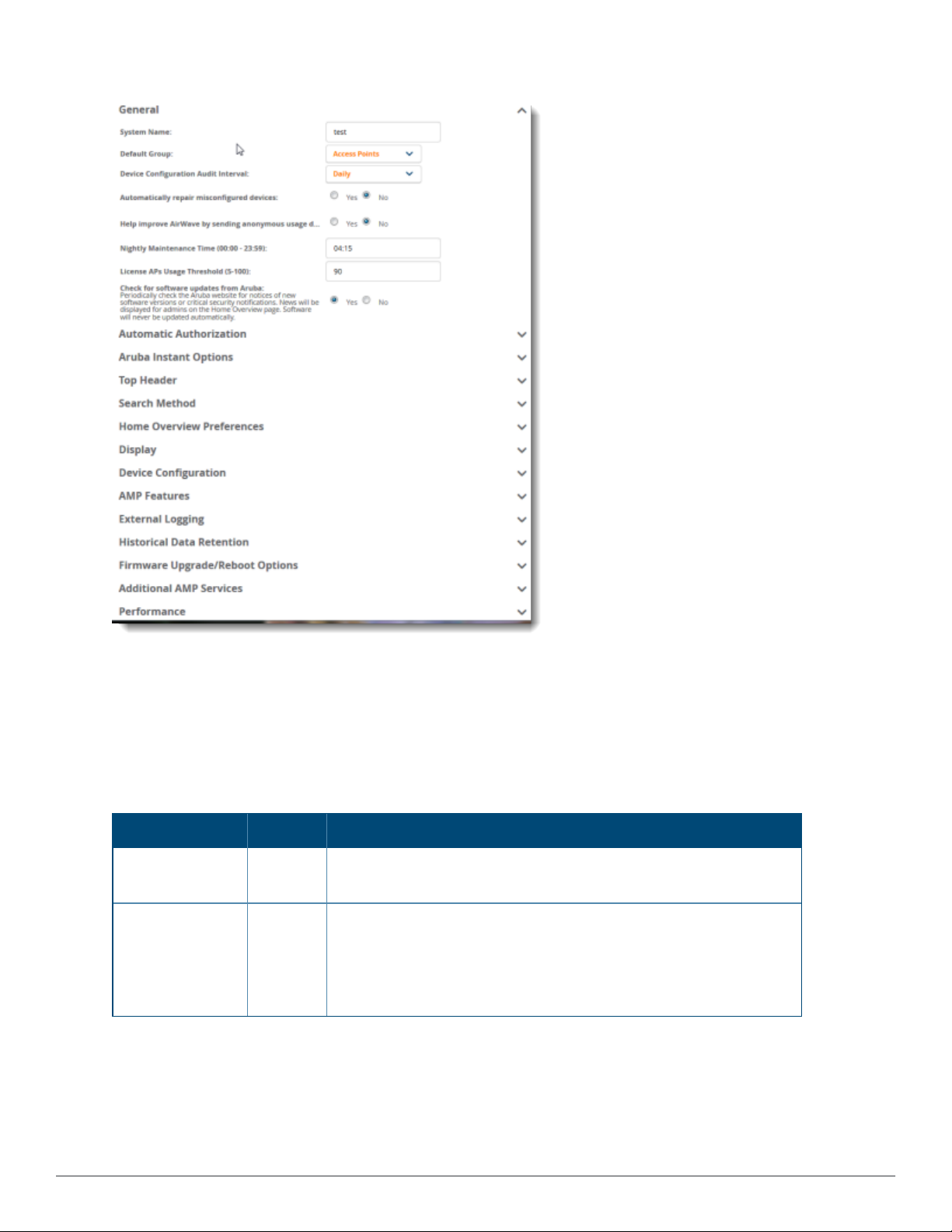
Figure 1: AMP Setup > General Settings
Whenever you save changes to these settings, AirWave applies them globally across the product for all users.
General Settings
Browse to the AMP Setup > General page, locate the General section, and enter the information described in
Table 1:
Table 1: AMP Setup >General > General Section Fields and Default Values
Setting Default Description
System Name Defines your name for your AirWave server using alphanumeric
characters.
Default Group Access
Points
Sets the device group that this AirWave server uses as the default for
device-level configuration. Select a device group from the drop-down
menu. A group must first be defined on the Groups > List page to
appear in this drop-down menu. For additional information, refer to
"Using Device Groups" on page 72.
18 | Configuring AirWave A irWave 8.2.9 | User Guide
Page 19

Table 1: AMP Setup >General > General Section Fields and Default Values (Continued)
Setting Default Description
Device
Configuration
Audit Interval
Automatically
repair
misconfigured
devices
Help improve
AirWave by
sending
anonymous usage
data
Nightly
Maintenance
Time (00:00 23:59)
Daily This setting defines the interval of queries which compares actual
device settings to the Group configuration policies stored in the
AirWave database. If the settings do not match, the AP is flagged as
mismatched and AirWave sends an alert via email, log, or SNMP.
NOTE: Enabling this feature with a frequency of Daily or more
frequently is recommended to ensure that your AP configurations
comply with your established policies. Specifying Never is not
recommended.
Disabled If enabled, this setting automatically reconfigures the settings on the
device when the device is in Manage mode and AirWave detects a
variance between actual device settings and the Group configuration
policy in the AirWave database.
Disabled If enabled, AirWave will send anonymous data to Aruba, which may be
used to improve the AirWave software.
04:15 Specifies the local time of day AirWave should perform daily
maintenance. During maintenance, AirWave cleans the database,
performs backups, and completes a few other housekeeping tasks.
Such processes should not be performed during peak hours of
demand.
License APs
Usage Threshold
Check for
software updates
90
Yes Enables AirWave to check automatically for multiple update types.
Sets a threshold to display an alert on the controller monitor page
when the license usage has reached this number.
Check daily for AirWave updates, to include enhancements, device
template files, important security updates, and other important news.
This setting requires a direct Internet connection via AirWave.
Automatic Authorization Settings
On the AMP Setup > General page, locate the Automatic Authorization section. These settings allow you to
control the conditions by which devices are automatically authorized into AP groups and folders. AirWave
validates the Folder and Group to ensure that both settings have been set to valid drop down options. Table 2
describes the settings and default values in this section.
AirWave 8.2.9 | User Guide Configuring AirWave | 19
Page 20

Table 2: AMP Setup > General > Automatic Authorization Fields and Default Values
Setting Default Description
Add New
New Device List Globally add new controllers and autonomous devices to:
Controllers and
Autonomous
Devices Location
Add New Thin APs
New Device List Globally add new thin APs to:
Location
Automatically
Authorized Virtual
Manage
Read/Write
Controller Mode
Aruba Instant Settings
l The New Device List (located in Devices > New).
l The same folder and group as the discovering device.
l The same group and folder of their closest IP neighbor on the
same subnet.
l Choose a group and folder. If you select this option, enter the
folder/group in the Auto Authorization Group and Auto
Authorization Folder fields that display.
NOTE: This setting can be overridden in Groups > Basic.
l The New Devices list.
l The same folder and group as the discovering device.
l The same group and folder of their closest IP neighbor on the
same subnet.
l Choose a group and folder. If you select this option, enter the
folder/group in the Auto Authorization Group and Auto
Authorization Folder fields that display.
NOTE: This setting can be overridden in Groups > Basic.
Specify whether Virtual Controller mode for Instant APs will be in
Manage Read/Write mode or Monitor Only mode.
A Virtual Controller can communicate with the AirWave server over a configurable communication port, and
authenticate to the server using a pre-shared key, and/or two-way certificate-based authentication using an SSL
certificate sent from AirWave to the Instant device.
The AMP Setup > General > Aruba Instant Options page includes the following Configuration settings:
Table 3: AMP Setup > General > ArubaInstantOptions Fields and Default Values
Setting Default Description
Communication
port
(443,1000-65534):
Security method
for adding new
Virtual Controllers:
443 By default, an Instant Virtual Controller communicates with AirWave
over port 443. If your enterprise has a security policy that restricts the
use of port 443 for inbound communication, use this field to change the
port the Virtual Controller uses to communicate with AirWave.
PSK Only
AirWave can use the following security methods to authenticate a
Virtual Controller to the AirWave server:
l PSK Only
l PSK and Certificate
l Certificate Only
If you enable certificate-based authentication, you are directed to the
AMP Setup > General > Upload SSLCertificate page, where you are
prompted to upload an certificate file in PEM format that contains both a
private key and certificate.
20 | Configuring AirWave A irWave 8.2.9 | User Guide
Page 21

Table 3: AMP Setup > General > ArubaInstantOptions Fields and Default Values (Continued)
Setting Default Description
Allow None-TPM
Devices
Configuration Only No By default, AirWave will push Instant configuration settings as well as
Yes If certificate-based authentication is enabled for the Virtual Controller,
AirWave allows low assurance, non-TPM device. This setting is
unavailable when PSK authentication is used.
AirWave settings such as RAPIDS settings and traps from an AirWave
group to a Virtual Controller assigned to that group. Select the Yes
option to push Instant configuration settings only.
If you select a security method that includes Certificate-based authentication, you must upload the a certificate
from a supported certificate authority to the AirWave server, as the default AirWave certificate will not be
recognized by the Instant AP, and will cause the SSL handshake to fail. Certificate authentication also requires
that the AMP IPaddress information configured on the Instant AP is a domain name, and not an IP address.
AirWave supports the following trusted certificate authorities:
l Chain 1: Trusted Root CA: C=SE, O=AddTrust AB, OU=AddTrust External TTP Network, CN=AddTrust External
CA Root Intermediate CA: C=GB, ST=Greater Manchester, L=Salford, O=COMODO CA Limited, CN=COMODO
High-Assurance Secure Server CA
l Chain 2: Trusted Root CA: C=US, O=GeoTrust Inc., CN=GeoTrust Global CA Intermediate CA: Subject: C=US,
O=Google Inc, CN=Google Internet Authority G2
l Chain 3: Trusted Root CA: C=US, O=VeriSign, Inc., OU=VeriSign Trust Network, OU=(c) 2006 VeriSign, Inc. -
For authorized use only, CN=VeriSign Class 3 Public Primary Certification Authority - G5 Intermediate CA:
C=US, O=VeriSign, Inc., OU=VeriSign Trust Network, OU=Terms of use at https://www.verisign.com/rpa (c)10,
CN=VeriSign Class 3 Secure Server CA - G3
l Root CA: Trusted Root CA: C=US, O=Equifax, OU=Equifax Secure Certificate Authority
If you enable certificate authentication, you are prompted to upload an SSLcertificate. you can view the current
AirWave certificate using the View Certificate link on that page, or click Change to upload a new certificate file
to the AirWave server.
Top Header Settings
The top header of each AirWave WebUI pagedisplays icons that provide counts on newly discovered devices,
device status, mismatches, rogues, clients, and both unacknowledged and severe alerts. These icons also provide
direct links for immediate access to key system components.
Figure 2: Header Statistics Icons
You can configure what is displayed in the top header for all pages, or for individual AirWave users.
To change the header statistic icons:
1. Navigate to AMP Setup > General, then scroll down to Top Header.
2. Choose the statistics.
3. Choose the devices.
4. Click Save.
Aconfirmation message does not appear when you make modifications to the top header statistic icons.
To change statistics that display for an AirWave user:
AirWave 8.2.9 | User Guide Configuring AirWave | 21
Page 22
1. Navigate to Home > User Info page, then scroll down to Top Header Stats.
2. Choose the statistics.
3. Choose the devices.
4. Click Save. These user settings will override the general settings on the AMP Setup page.
Search Method
On the AMP Setup > General page, locate the Search Method section. Select one of the following drop down
options as the system-wide default search method. This default search type will be used when a user types an
entry in the Search field and then clicks Enter without selecting a specific search type.
l Use System Defaults: The Search Method will be based on the system-wide configuration setting. This
method is configured on the AMP Setup > General page.
l Active clients + historical clients (exact match) + all devices: Commonly referred to as Quick Search, this looks
at all active and historical clients and all devices. This search is not case-sensitive. The results of this search
display in a pop up window rather than on the Home > Search page. This pop up window includes top-level
navigation that allows you to filter the results based on Clients, APs, Controllers, and Switches.
l Active clients + all categories: This looks at all active clients (not historical) and all categories. This search is not
case-sensitive.
l Active clients + all categories (exact match): This looks at all active clients (not historical) and all categories.
This search returns only matches that are exactly as typed (IP, user name, device name, etc). This search is
case-sensitive for all searched fields.
l Active + historical clients + all categories: This looks at all active and historical clients and all categories. This
search is not case-sensitive.
l Active + historical clients + all categories (exact match): This looks at all active and historical clients and all
categories. This search returns only matches that are exactly as typed (IP, user name, device name, etc). This
search is case-sensitive for all searched fields.
Aconfirmation message does not appear after you make modifications to Search Preferences.
Per-user search preferences can be set in the Home > User Info page.
Home Overview Preferences
On the AMP Setup > General page, locate the Home Overview Preferences section. Table 4 describes the
settings and default values in this section.
Table 4: AMP Setup > General > Home Overview Preferences Fields and Default Values
Setting Default Description
Configure Channel
Busy Threshold
Channel Busy
Threshold (%)
Yes Whether you want to configure the threshold at which a channel is
considered to be busy at the Top Folders By Radio Channel Usage
Overview widget.
n/a The threshold percent at which the radio channel is considered busier
than normal. This field is only available if the Configure Channel Busy
Threshold setting is Yes.
22 | Configuring AirWave A irWave 8.2.9 | User Guide
Page 23

Display Settings
On the AMP Setup > General page, locate the Display section and select the options to appear by default in
new device groups.
Changes to this section apply across all of AirWave. These changes affect all users and all new device groups.
Table 5 describes the settings and default values in this section.
Table 5: AMP Setup > General > Display Fields and Default Values
Setting Default Description
AP Fully Qualified
Domain Name
Options
Show vendorspecific device
settings for
No Sets AirWave to use fully qualified domain names for APs instead of the
AP name. For example, ‘testap.yourdomain.com; would be used instead
of ‘testap.’ Select one of the following options:
l Don’t use FQDN - This default value specifies that the fully qualified
domain name will not be used.
l Use AP Name with FQDN - The AP name will prepend the FQDN, for
example “somehostname (my.hostname.com).” Note that if the AP
name is not present, then the FQDN will still appear in parenthesis.
l Use only FQDN - Only the fully qualified domain name will be used.
NOTE: This option is supported only for Cisco IOS, Dell Networking WSeries, Aruba Networks, and Alcatel-Lucent devices.
All Devices Displays a drop-down menu that determines which Group tabs and
options are viewable by default in new groups, and selects the device
types that use fully qualified domain names. This field has three options,
as follows:
l All devices—When selected, AirWave displays all Group tabs and
setting options.
l Only devices on this AMP—When selected, AirWave hides all
options and tabs that do not apply to the APs and devices currently on
AirWave.
l Selected device type—When selected, a new field appears listing
many device types. This option allows you to specify the device types
for which AirWave displays group settings. You can override this
setting.
Look up device and
wireless user
Yes Enables AirWave to look up the DNS for new user hostnames. This setting
can be turned off to troubleshoot performance issues.
hostnames
DNS Hostname
Lifetime
Device
Troubleshooting
Hint
AirWave 8.2.9 | User Guide Configuring AirWave | 23
24 hours Defines the length of time, in hours, for which a DNS server hostname
remains valid on AirWave, after which AirWave refreshes DNS lookup:
l 1 hour
l 2 hours
l 4 hours
l 12 hours
l 24 hours
N/A The message included in this field is displayed along with the Down if a
device’s upstream device is up. This applies to all APs and controllers but
not to routers and switches.
Page 24

Device Configuration Settings
Locate the Device Configuration section and adjust the settings. Table 6 describes the settings and default
values of this section.
Table 6: AMP Setup > General > Device Configuration Section Fields and Default Values
Setting Default Description
Guest User
Configuration
Allow WMS Offload
configuration in
monitor-only mode
Allow disconnecting
users while in
monitor-only mode
Use Global Aruba
Configuration
Disabled Enables or prevents guest users to/from pushing configurations to
devices. Options are Disabled (default), Enabled for Devices in
Manage(Read/Write), Enabled for all Devices.
No When Yes is selected, you can enable the ArubaOS WMS offload
feature on the Groups > Basic page for WLAN switches in Monitor
Only mode. Enabling WMS offload does not cause a controller to
reboot. This option is supported only for Aruba and Dell Networking
W-Series devices.
No Sets whether you can deauthenticate a user for a device in monitor-
only mode. If set to No, the Deauthenticate Client button for in a
Clients > Client Detail page is enabled only for Managed devices.
No Enables Aruba configuration profile settings to be globally configured
and then assigned to device groups. If disabled, settings can be
defined entirely within Groups > Controller Configand Groups
>Switch Config instead of globally.
NOTE: Changing this setting may require importing configuration on
your devices. When an existing Aruba configuration setup is to be
converted from global to group, follow these steps:
1. Set all the devices to Monitor Only mode before setting the flag.
2. Each device Group will need to have an import performed from
the Device Configuration page of a controller in the AMP group.
3. All of the thin APs need to have their settings imported after the
device group settings have finished importing.
4. If the devices were set to Monitor Only mode, set them back to
Managed mode.
AMP Features
Locate the AMPFeatures section and adjust settings for VisualRF, RAPIDS, and AirWave Glass. Table 7 describes
these settings and default values.
Table 7: AMP Setup Setup > General > AMP Features Fields and Default Values
Setting Default Description
Display VisualRF No Enable or disable the VisualRF navigation tab.
Display RAPIDS No Enable or disable the RAPIDS navigation tab.
24 | Configuring AirWave A irWave 8.2.9 | User Guide
Page 25

Table 7: AMP Setup Setup > General > AMP Features Fields and Default Values (Continued)
Setting Default Description
Hide setup pages
from non-admin
users
Allow role based
report visibility
Enable Central
Authentication
Yes Restrict access to following pages to users with the AMP Administration
role only:
l VisualRF > Setup
l AMP Setup > NMS
l RAPIDS > Score Override
l RAPIDS > Rules
l RAPIDS > Setup
l System > Triggers
Yes Enable or disable role-based reporting in AMP. When disabled, reports
can only be generated with by-subject visibility.
Yes Toggles on or off single-sign on (SSO) authentication between AirWave
and AirWave Glass.
Service
Central
Authentication
Hostname
If the Central Authentication Service is enabled and the managed AMP is
attached to AirWave Glass, this field is automatically populated, and you
don't need to configure the hostname.
External Logging Settings
Locate the External Logging section and adjust settings to send audit and system events to an external syslog
server. Table 8 describes these settings and default values. You can also send a test message using the Send
Test Message button after enabling any of the logging options.
For information about creating triggers in order to receive event notifications, see "Creating New Triggers" on
page298.
Table 8: AMP Setup > General > External Logging Section Fields and Default Values
Setting Default Description
Include event log
messages
Syslog Server N/A Enter the IP address of the syslog server. Note that this field is hidden if
Syslog Port 514 Enter the port of the syslog server. Note that this field is hidden if both
Event log facility local1 Select the facility for the event log from the drop-down menu. This field is
Include audit log
messages
No Select Yes to send event log messages to an external Syslog server.
NOTE: If you enable event logging, other options to configure the Syslog
server and enable logging using Common Event Format (CEF) become
available.
both "Include event log messages" and "Include audit log messages" are
set to No.
"Include event log messages" and "Include audit log messages" are set to
No.
only available if the "Include event log messages" setting is Yes.
No Select Yes to send audit log messages to an external syslog server.
AirWave 8.2.9 | User Guide Configuring AirWave | 25
Page 26

Table 8: AMP Setup > General > External Logging Section Fields and Default Values (Continued)
Setting Default Description
Audit log facility local1 Select the facility for the audit log from the drop-down menu. This field is
only available if the "Include audit log messages" setting is Yes
Send Test Message N/A If messaging is enabled and a server and port are configured, click this
button to send a test message. Upon completion, a message will appear
at the top of this page indicating that the message was sent successfully.
Historical Data Retention Settings
Locate the Historical Data Retention section and specify the number of days you want to keep client session
records and rogue discovery events. Table 9 describes the settings and default values of this section. Many
settings can be set to have no expiration date.
Table 9: AMP Setup > General > Historical Data Retention Fields and Default Values
Setting Default Description
Inactive Client and
VPN User Data (01500 days, zero
disables)
Client Association
and VPN Session
History (0-550
days, zero
disables)
Tag History (0-550
days, zero
disables)
Rogue AP
Discovery Events
(14-550 days, zero
disables)
Reports (0-550
days, zero
disables)
Automatically
Acknowledge
Alerts(0-550 days,
zero disables)
60 Defines the number of days AirWave stores basic information about
inactive clients and VPN users. A shorter setting of 60 days is
recommended for customers with high user turnover such as hotels. The
longer you store inactive user data, the more hard disk space you require.
14 Defines the number of days AirWave stores client and VPN session
records. The longer you store client session records, the more hard disk
space you require.
14 Sets the number of days AirWave retains location history for Wi-Fi tags.
14 Defines the number of days AirWave stores Rogue Discovery Events. The
longer you store discovery event records, the more hard disk space you
require.
60 Defines the number of days AirWave stores Reports. Large numbers of
reports, over 1000, can cause the Reports > Generated page to be slow to
respond.
14 Defines automatically acknowledged alerts as the number of days AirWave
retains alerts that have been automatically acknowledged. Setting this
value to 0 disables this function, and alerts will never expire or be deleted
from the database.
Acknowledged
Alerts(0-550 days,
zero disables)
26 | Configuring AirWave A irWave 8.2.9 | User Guide
60 Defines the number of days AirWave retains information about
acknowledged alerts. Large numbers of Alerts, over 2000, can cause the
System > Alerts page to be slow to respond.
Page 27

Table 9: AMP Setup > General > Historical Data Retention Fields and Default Values (Continued)
Setting Default Description
Radius/ARM/IDS
Events(0-550 days,
zero disables)
Archived Device
Configurations (0100, zero disables)
Archive device
configs even if they
only have rogue
classifications
Guest Users (0-550
days, zero
disables)
Inactive SSIDs (0550 days, zero
disables)
Inactive Interfaces
(0-550 days, zero
disables)
14 Defines the number of days AirWave retains information about RADIUS,
ARM, and IDS events. Setting this value to 0 disables this function, and the
information will never expire or be deleted from the database.
10 Defines the number of configurations that will be retained for archived
devices. Whether rogue information is included depends on the setting of
the Archive device configs even if they only have rogue
classifications setting.
No Sets whether to archive device configurations even if the device only has
rogue classifications.
30 Sets the number of days that AirWave is to support any guest user. A value
of 0 disables this function, and guest users will never expire or be deleted
from the AirWave database.
425 Sets the number of days AirWave retains historical information after
AirWave last saw a client on a specific SSID. Setting this value to 0 disables
this function, and inactive SSIDs will never expire or be deleted from the
database.
425 Sets the number of days AirWave retains inactive interface information
after the interface has been removed or deleted from the device. Setting
this value to 0 disables this function, and inactive interface information will
never expire or be deleted from the database.
Interface Status
History (0-550
days, zero
disables)
Interfering Devices
(0-550 days, zero
disables)
Device Events
(Syslog, Traps)(131 days)
Mesh Link History
(0-550 days)
Device Uptime (0120 months, zero
disables)
425 Sets the number of days AirWave retains historical information on
interface status. Setting this value to 0 disables this function.
14 Sets the number of days AirWave retains historical information on
interfering devices. Setting this value to 0 disables this function.
2 Sets the number of days AirWave retains historical information on device
events such as syslog entries and SNMP traps. Setting this value to 0
disables this function. Refer to "Viewing Device Events" on page 295.
NOTE: If your data table has more than 5 million rows, AirWave will
truncate the device event retention data. In this case, the "number of days"
setting becomes "number of hours."
30 Sets the number of days AirWave retains historical information for mesh
links.
60 Sets the number of months AirWave retains historical information on
device uptime. Setting this value to 0 disables this function.
AirWave 8.2.9 | User Guide Configuring AirWave | 27
Page 28

Table 9: AMP Setup > General > Historical Data Retention Fields and Default Values (Continued)
Setting Default Description
Client Data
Retention Interval
(1-425 days)
UCC Call History
(1-30 days)
UCC Call Details
(1-7 days)
Config Job
Retention Interval
(1-31 days)
425 Sets the number of days AirWave retains historical information for clients.
30 Sets the number of days that calls remain in AirWave's call history.
2 Sets the number if days that the AirWave retains details for individual calls.
31 Sets the number of days AirWave retains information about configuration
jobs.
Firmware Upgrade/Reboot Options
Locate the Firmware Upgrade/Reboot Options section and adjust settings as required. This section allows
you to configure the default firmware upgrade behavior for AirWaveTable 10
Table 10 describes the firmware upgrade and reboot options.
Table 10: AMP Setup > General > Firmware Upgrade Defaults Fields and Default Values
Setting Default Description
Allow firmware
upgrades in
monitor-only mode
No If Yes is selected, AirWave upgrades the firmware for APs in Monitor
Only mode. When AirWave upgrades the firmware in this mode, the
desired configuration are not be pushed to AirWave. Only the firmware is
applied. The firmware upgrade may result in configuration changes
AirWave does not correct those changes when the AP is in Monitor Only
mode.
Allow Rebooting
Monitor Only
Devices
Enable firmware
distribution via http
Fast Download No When fast download is enabled, standalone IAPs in the same RF zone are
Sequential Reboot No When sequential reboot is enabled, the APs in the same RF zone will
No If Yes is selected, AirWave can reboot devices in Monitor Only mode.
No By default, we use HTTPS and require user log in for firmware updates.
NOTE: For IAPs running versions earlier than Instant 3.4.0.0, set this
option to "Yes" in order to get firmware updates using HTTP.
grouped so that they can download the image from each other. This
assumes that the APs are behind the same firewall so that they can reach
each other, thereby making the firmware download faster.
reboot sequentially. At any given time, only one AP is being rebooted. As a
result, users can use another AP that is visible in RF and have
uninterrupted service.
28 | Configuring AirWave A irWave 8.2.9 | User Guide
Page 29

Table 10: AMP Setup > General > Firmware Upgrade Defaults Fields and Default Values (Continued)
Setting Default Description
Maximum
Interleaved Jobs (1-
20)
Maximum
Interleaved Devices
Per Job (1-1000)
Failures before
stopping (0-20, zero
disables)
Failure timeout (560 mins)
DRT upgrade failure
timeout (2-30 mins)
Number of tries in
failure (1-4)
Periodic run failed
upgrade interval
20 Defines the number of jobs AirWave runs at the same time. A job can
include multiple APs. When jobs are started by multiple users, AirWave will
interleave upgrades so that one user's job does not completely block
another’s.
20 Defines the number of devices that can be in the process of upgrading at
the same time. Within a single job, AirWave may start the upgrade
process for up to this number of devices at the same time. However, only
one device will be actively downloading a firmware file at any given time.
1 Sets the default number of upgrade failures before AirWave pauses the
upgrade process. User intervention is required to resume the upgrade
process. Setting this value to 0 disables this function.
60 Sets the timeout for an upgrade attempt.
6 Sets the timeout for a Downloadable Regulatory Table (DRT) upgrade
attempt.
1 Sets the number of retry attempts.
Disabled Set the length of time AirWave retries running a failed upgrade.
Additional AMP Services
Locate the AdditionalAMP Services section, and adjust settings as required. Table 11 describes the settings
and default values of this section.
Table 11: AMP Setup > General > Additional AMP Services Fields and Default Values
Setting Default Description
Enable FTP Server No Enables or disables the FTP server on AirWave. The FTP server is only
used to manage Aruba AirMesh and Cisco Aironet 4800 APs. Best
practice is to disable the FTP server if you do not have any supported
devices in the network.
AirWave 8.2.9 | User Guide Configuring AirWave | 29
Page 30

Table 11: AMP Setup > General > Additional AMP Services Fields and Default Values (Continued)
Setting Default Description
Enable RTLS
Collector
No Enables or disables the RTLS Collector, which is used to allow
ArubaOScontrollers to send signed and encrypted RTLS (real time
locating system) packets to VisualRF; in other words, AirWave becomes
the acting RTLS server. The RTLS server IP address must be configured on
each controller. This function is used for VisualRF to improve location
accuracy and to locate chirping asset tags. This function is supported only
for Dell Networking W-Series, Alcatel-Lucent, and Aruba Networks
devices.
If Yes is specified, the following additional fields appear. These
configuration settings should match the settings configured on the
controller:
l RTLS Port—Specify the port for the AirWave RTLS server.
l RTLS Username—Enter the user name used by the controller to
decode RTLS messages.
l RTLS Password—Enter the RTLS server password that matches the
controller’s value.
l Confirm RTLS Password—Re-enter the RTLS server password.
Use Embedded
Mail Server
Yes Enables or disables the embedded mail server that is included with
AirWave.
Mail Relay Server Optional If you enable the "Use embedded mail server" option, enter information
for an optional mail relay server. This field supports a Send Test Email
button for testing server functionality. Click this button to enter valid email
addresses.
Process user
roaming traps from
Cisco WLC
Enable AMON data
collection
Enable Clarity Data
Collection
Enable Traffic
Analysis Data
Collection
Traffic Analysis
Storage Allocated
(GiB)
Yes Whether AirWave should parse client association and authentication traps
from Cisco WLC controllers to give real time information on users
connected to the wireless network.
Yes Allows AirWave to collect enhanced data from Aruba devices on certain
firmware versions. See the Best Practices Guide on the Home >
Documentation page for more details
NOTE: When enabling AMON, auditing should be set to daily and have
been successful at least once to allow AirWave to calculate the proper
BSSIDs per radio. If these BSSIDs do not exist, clients are dropped
because they do not have any corresponding BSSIDs in the AirWave
database. Auditing should be set to daily because the BSSIDs are kept in
cache memory and cleared every 24 hours.
Yes Allows AirWave to collect enhanced Clarity Monitoring data from Aruba
devices running ArubaOS 6.4.3 and later versions
Yes If AMON is enabled for a controller, you can enable AirWave to collect
Traffic Analysis data from the controller by setting this to Yes. When
enabled, the Home > Traffic Anaylsis dashboard is available in the
WebUI.
50 If Traffic Analysis Data Collection is enabled, you can specify the amount
of storage to allocate.
30 | Configuring AirWave A irWave 8.2.9 | User Guide
Page 31

Table 11: AMP Setup > General > Additional AMP Services Fields and Default Values (Continued)
Setting Default Description
Enable UCC Data
Collection
Enable UCC Calls
Stitching
(Heuristics)
Prefer AMONvs
SNMP Polling
Yes Enables controllers to send UCC data to AirWave. For this feature to work,
AirWave must be a management server on the controller, the AMON port
is set up for UDP port 8211, and the controller profile has UCC monitoring
enabled.
Yes Enables caller-to-callee call stitching for non-SDN deployments. You
should turn off this option for NATand BOC deployments.
Yes
Prefer AMON is a configuration setting which causes AirWave to use an
AMON feed to obtain client monitoring information from a controller
rather than polling it via SNMP. When you enable this setting, values such
as AP lists and rogue AP lists are still polled via SNMP, but the bulk of
client monitoring information is delivered via AMON.
NOTE:
l Auditing needs to have been successful at least once to allow AirWave
to calculate the proper BSSIDs per radio.
l When Prefer AMON is enabled, the controller must be configured to
send AMON to AirWave.
l The network path from the controller to the AirWave server must allow
traffic on UDP port 8211.
l The controller routinely sends AMON in large UDP packets, (up to 30K
bytes). Before enabling this setting, ensure the network path from the
controller to AirWave can pass such large packets intact.
l This setting should only be used in a network environment with low
levels of UDPpacket loss, as the loss of a single Ethernet frame will
potentially result in the loss of up to 30K bytes worth of data.
Enable Syslog and
SNMP Trap
Collection
Require SSH host
Yes This option specifies whether traps used to detect roaming events, auth
failures, AP up/down status, and IDS events will still be collected if they
are sent by managed devices.
No
This setting reserved for future use.
key verification
Validate PAPI key No Security improvements in AirWave 8.2.1 and later releases allow you to
specify a custom PAPIkey and require PAPI key validation. If you select the
Yes option, you are prompted to enter a custom PAPI key
Disable TLS 1.0 and
1.1
Yes This option is set to Yes by default. In order for Aruba switches to
automatically check-in to AirWave by ZTP, you must change this option to
No. If you select No, you must restart AMP.
Performance Settings
Locate the Performance section. Performance tuning is unlikely to be necessary for many AirWave
deployments, and likely provides the most improvements for customers with extremely large Pro or Enterprise
installations. Please contact Aruba support if you think you might need to change any of these settings. Table 12
describes the settings and default values of this section.
AirWave 8.2.9 | User Guide Configuring AirWave | 31
Page 32

Table 12: AMP Setup> General > Performance Fields and Default Values
Setting Default Description
Monitoring
Processes
Maximum number
of configuration
processes
Maximum number
of audit processes
SNMP Fetcher
Count (2-6)
Verbose Logging
of SNMP
Configuration
Based on
the number
of cores for
your server
5 Increases the number of processes that are pushing configurations
3 Increases the number of processes that audit configurations for
2 Specify the number of SNMPv2 fetchers.
No Enables or disables logging detailed records of SNMP configuration
Optional setting configures the throughput of monitoring data.
Increasing this setting allows AirWave to process more data per
second, but it can take resources away from other AirWave
processes. Contact Aruba support if you think you might need to
increase this setting for your network. Also note that the value
range varies based on the number of available process cores.
to your devices, as an option. The optimal setting for your network
depends on the resources available, especially RAM. Contact Aruba
support if you think you might need to increase this setting for your
network.
your devices, as an option. The optimal setting for your network
depends on the resources available, especially RAM. Contact Aruba
support if you are considering increasing this setting for your
network.
information.
SNMP Rate
Limiting for
Monitored
Devices
Client Association
Relevance Factor
No When enabled, AirWave fetches SNMP data more slowly, potentially
reducing device CPU load.
We recommend enabling this global setting if your network contains
a majority of legacy controllers (800, 2400, 5000, or controllers that
use Supervisor Module II). If your network mainly uses newer
(30000 Series, 600 Series, or the M3 module in the 6000 series), we
strongly recommend disabling this setting.
0 days
(disabled)
Use this setting to hide old client information from clients lists and
client search results. For example, a setting of 3 limits the historical
client data displayed in client lists and search results to client
sessions that have been disconnected within the last three days.
When this value is set to 1, client lists and search results display
only the client history for the previous day.
This time range can be set from 0-550 days, where a value of zero
disables this feature and makes available all historical client data. A
shorter time period improves search performance and allows client
lists to display more rapidly, though it will also display fewer results.
32 | Configuring AirWave A irWave 8.2.9 | User Guide
Page 33

Table 12: AMP Setup> General > Performance Fields and Default Values (Continued)
Setting Default Description
RAPIDS
Processing
Priority
RAPIDS custom
process limit (1-
16)
Low Defines the processing and system resource priority for RAPIDS in
relation to AirWave as a whole.
When AirWave is processing data at or near its maximum capacity,
reducing the priority of RAPIDS can ensure that processing of other
data (such as client connections and bandwidth usage) is not
adversely impacted.
The default priority is Low. You can also tune your system
performance by changing group poll periods.
If you select Custom for the priority, then also specify the RAPIDS
custom process limit.
1 when
Custom is
specified for
the RAPIDS
Processing
Priority.
Sets the maximum number of monitoring process assigned to
RAPIDS work. Note that this option is only available if Custom is
specified for the RAPIDS Processing Priority.
Defining Network Settings
The next steps in setting up AirWave are to configure the network interface, DNS settings, NTP servers, and static
routes.
Figure 3 illustrates the contents of the AMP Setup > Network page when setting up an IPv4 interface.
Optionally, you can configure an IPv6 interface. For information, see "Primary Network Interface Settings" on
page34.
AirWave 8.2.9 | User Guide Configuring AirWave | 33
Page 34

Figure 3: Network Page
Specify the network configuration options described in the sections that follow to define the AirWave network
settings. Select Save when you have completed all changes on the AMP Setup > Network page, or select
Revert to return to the last settings. Save restarts any affected services and may temporarily disrupt your
network connection.
Primary Network Interface Settings
Locate the Primary Network Interface section. The information in this sections should match what you
defined during initial network configuration and should not require changes. Table 13 describes the settings and
default values.
Table 13: Primary Network Interface Fields and Default Values
Setting Default Description
IPv4 Address None Sets the IPv4 address of the AirWave network interface.
NOTE: This address must be a static IP address.
Hostname None Sets the DNS name assigned to the AirWave server.
Subnet Mask None Sets the subnet mask for the primary network interface.
IPv4 Gateway None Sets the default gateway for the network interface.
IPv6 Enabled No By selecting Yes, you can enter an optional IPv6 address and gateway
address.
IPv6 Address None Sets the IPv6 address of the AirWave network interface.
34 | Configuring AirWave A irWave 8.2.9 | User Guide
Page 35

Table 13: Primary Network Interface Fields and Default Values (Continued)
Setting Default Description
IPv6 Gateway None Sets the default gateway for the network interface.
Primary DNS IP None Sets the primary DNS IP address for the network interface.
Secondary DNS IP None Sets the secondary DNS IP address for the network interface.
Secondary Network Interface Settings
Locate the Secondary Network Interface section. The information in this section should match what you
defined during initial network configuration and should not require changes. Table 14 describes the settings and
default values.
Table 14: Secondary Network Interface Fields and Default Values
Setting Default Description
Enabled No Select Yes to enable a secondary network interface. You will be
prompted to define the IP address and subnet mask.
IP Address None Specify the IP address of the AirWave secondary network.
NOTE: This address must be a static IP address. AirWave supports
IPv4 and IPv6 addresses.
Subnet Mask None Specify the subnet mask for the secondary network interface.
Network Time Protocol (NTP) Settings
On the AMP Setup > Network page, locate the Network Time Protocol (NTP) section. The Network Time
Protocol is used to synchronize the time between AirWave and your network’s NTP server. NTP servers
synchronize with external reference time sources, such as satellites, radios, or modems.
SpecifyingNTP servers is optional. NTP servers synchronize the time on the AirWave server, not on individual
access points.
To disable NTP services, clear both the Primary and Secondary NTP server fields. Any problem related to
communication between AirWave and the NTP servers creates an entry in the event log. Table 15 describes the
settings and default values in more detail. For more information on ensuring that AirWave servers have the
correct time, please see http://support.ntp.org/bin/view/Servers/NTPPoolServers.
Table 15: AMP Setup > Network > Secondary Network Fields and Default Values
Setting Default Description
Primary ntp1.yourdomain.com Sets the IP address or DNS name for the primary NTP server.
Secondary ntp2.yourdomain.com Sets the IP address or DNS name for the secondary NTP server.
Static Routes
On the AMP Setup > Network page, locate the Static Routes area. This section displays network, subnet
mask, and gateway settings that you have defined elsewhere from a command-line interface.
AirWave 8.2.9 | User Guide Configuring AirWave | 35
Page 36

This section does not enable you to configure new routes or remove existing routes.
What Next?
l Go to additional tabs in the AMP Setup section to continue additional setup configurations. The next section
describes AirWave roles.
l Complete the required configurations in this chapter before proceeding. Aruba support remains available to
you for any phase of AirWave configuration.
Creating AirWave Users
AirWave installs with only one user—the admin, who is authorized to perform the following functions:
l Define additional users with varying levels of privilege, be it manage read/write or monitoring.
l Limit the viewable devices as well as the level of access a user has to the devices.
Each general user that you add must have a user name, a password, and a role. Use unique and meaningful user
names as they are recorded in the log files when you or other users make changes in AirWave.
Username and password are not required if you configure AirWave to use RADIUS, TACACS, or LDAP
authentication. You do not need to add individual users to the AirWave server if you use RADIUS, TACACS, or
LDAP authentication.
The user role defines the user type, access level, and the top folder for that user. User roles are defined on the
AMP Setup > Roles page. Refer to the previous procedure in this chapter for additional information, "Creating
AirWave User Roles" on page 38.
The admin user can provide optional additional information about the user, including the user's real name, email
address, phone number, and so forth.
Perform the following steps to display, add, edit, or delete AirWave users of any privilege level. You must be an
admin user to complete these steps.
1. Go to the AMP Setup > Users page. This page displays all users currently configured in AirWave, as shown in
Figure 4.
Figure 4: AMP Setup > Users Page
2. Select Add to create a new user, select the pencil icon to edit an existing user, or select a user and select
Delete to remove that user from AirWave. When you select Add or the edit icon, the Add User page appears,
illustrated in Figure 5.
Current users cannot change their own role. The Role drop-down field is disabled to prevent this.
36 | Configuring AirWave A irWave 8.2.9 | User Guide
Page 37

Figure 5: AMP Setup > Users > Add/Edit User Page
3. Enter or edit the settings on this page. Table 16 describes these settings.
Table 16: AMP Setup > Users > Add/Edit User Fields and Default Values
Setting Default Description
Username None Sets the user name for the user who logs in to AirWave. This user name is
displayed in AirWave log files.
Role None Specifies the user’s Role, which defines the Top viewable folder as well as the
type and access level of the user specified in the previous field.
The admin user defines user roles on the AMP Setup > Roles page, and each
user in the system is assigned to a role.
Password None Sets the password for the user being created or edited. Enter an alphanumeric
string without spaces, and enter the password again in the Confirm Password
field. AirWave strengthens user passwords with SHA512 encryption.
NOTE: Because the default user's password is identical to the Name, you should
change this password. You will be logged out and asked to enter your new
password.
Name None Allows you to define an optional and alphanumeric text field that takes note of the
user's actual name.
Email
Address
None Allows you to specify a specific email address that will propagate throughout
many additional pages in AirWave for that user, including reports, triggers, and
alerts.
Phone None Allows you to enter an optional phone number for the user.
Notes None Enables you to cite any additional notes about the user, including the reason they
were granted access, the user's department, or job title.
AirWave 8.2.9 | User Guide Configuring AirWave | 37
Page 38

4. Select Add to create the new user, Save to retain changes to an existing user, or Cancel to cancel out of this
screen. The user information you have configured appears on the AMP Setup > Users page, and the user
propagates to all other AirWave pages and relevant functions.
AirWaveenablesuser roles to be created with access to folders within multiple branches of the overall
hierarchy. This feature assists non-administrator users who support a subset of accounts or sites within a single
AirWave deployment, such as help desk or IT staff.
Configuring AirWave User Roles
The AMP Setup > Roles page defines the viewable devices, the operations that can be performed on devices,
and general AirWave access. User roles can be created that provide users with access to folders within multiple
branches of the overall hierarchy. This feature assists non-administrative users, such as help desk or IT staff, who
support a subset of accounts or sites within a single AirWave deployment. You can restrict user roles to multiple
folders within the overall hierarchy even if they do not share the sametop-level folder. Non-admin users are only
able to see data and users for devices within their assigned subset of folders.
User Roles and VisualRF
VisualRF uses the sameuser roles as defined for AirWave. Users can see floor plans that contain an AP to which
they have access in AirWave, although only visible APs appear on the floor plan. VisualRF users can also see any
building that contains a visible floor plan and any campus that contains a visible building.
In VisualRF > Setup > Server Settings, the Restrict visibility of empty floor plans to the user that
created them configuration option allows you to restrict the visibility of empty floor plans to the role of the
userwho created them. By default, this setting is set to No.
When a new role is added to AirWave, VisualRF must be restarted for the new user to be enabled.
Creating AirWave User Roles
Roles define the capabilities a user has access to and the privileges and views available for device groups and
devices in AirWave. The available configuration options differ for each role type.
Most users will see two sections on this page: Role and Guest User Preferences. The Guest User
Preferences section appears only if Guest User Configuration is enabled in AMP Setup > General.
If you want to create a user role, log in to AirWave as admin and follow these steps:
1. Go to the AMP Setup > Roles and click Add.
2. Enter a name for the user role, select options, and click Add. Figure 6 shows a role named Traffic Analysis
being created.
38 | Configuring AirWave A irWave 8.2.9 | User Guide
Page 39

Figure 6: Adding a Non-Admin Role Named Traffic Analysis
3. Enter additional settings on this page.
Figure 7 shows the newly created Traffic Analysis Admin role in the Role page.
Figure 7: Newly Created Traffic Analysis Admin Role
AMPAdministrator Role
The following table describes the available settings and default values for the AMP Administrator role.
AirWave 8.2.9 | User Guide Configuring AirWave | 39
Page 40

Table 17: AMP Setup > Roles > Add/Edit Roles Fields and Default Values for AMP Administrator Role
Setting Default Description
Name None Sets the administrator-definable string that names the role. The role
name should indicate the devices and groups that are viewable, as well
as the privileges granted to that role.
Enabled Yes Disables or enables the role. Disabling a role prevents all users of that
role from logging in to AirWave.
Type Device
Manager
Aruba Controller
Role
Allow user to
disable timeout
Custom Message none A custom message can also be included.
Disabled Enables or disables Single Sign-On for the role. If enabled, allows the
No Whether a user can disable AirWave’s timeout feature.
Defines the type of role.
AirWave Administrator—Grants full access to AirWave and all the
devices, thecapability to create new users, and access to AMP Setup,
VisualRF > Setup, VisualRF > Audit Log, System > Event Log, and
System > Performance pages.
user read-only access or direct access to the Aruba controller UIs from
quick links in the WebUI without having to enter credentials for the
controller.
Table 18: AMP Setup > Roles > Add/Edit Roles Fields and Default Values for Device Manager Role
Setting Default Description
Name None Sets the administrator-definable string that names the role. The role name
should indicate the devices and groups that are viewable, as well as the
privileges granted to that role.
Enabled Yes Disables or enables the role. Disabling a role prevents all users of that role
from logging in to AirWave.
Type Device
Manager
40 | Configuring AirWave A irWave 8.2.9 | User Guide
Defines the type of role.
Device Manager—Provides access to a limited number of devices and groups
based on the Top folder and varying levels of control based on the Access
Level.
Page 41

Table 18: AMP Setup > Roles > Add/Edit Roles Fields and Default Values for Device Manager Role
(Continued)
Setting Default Description
Access Level Monitor
(Read Only)
Defines the privileges the role has over the viewable device. AirWave supports
three privilege levels, as follows:
l Manage (Read/Write)—Provides the capability to modify, remove, and
view information for devices and groups. Selecting this option causes a new
field, Allow authorization of Devices, to appear on the page, and is
enabled by default.
l Audit (Read Only)—Provides the capability to view devices and groups
and the Device Configuration page, which may contain sensitive
information like AP passwords.
l Monitor (Read Only)—Provides the capability to view devices and groups
and VisualRF.
Top Folder Top Defines the highest viewable folder for the role. The role is able to view all
devices and groups contained by the specified top folder. The top folder and its
subfolders must contain all of the devices in any of the groups it can view.
NOTE: AirWave enables user roles to be created with access to folders within
multiple branches of the overall hierarchy. This feature assists nonadministrator users who support a subset of accounts or sites within a single
AirWave deployment, such as help desk or IT staff.
User roles can be restricted to multiple folders within the overall hierarchy,
even if they do not share the same top-level folder. Non-administrator users
are only able to see data and users for devices within their assigned subset of
folders.
Allow
Authorization
Yes
NOTE: This option is only available when the AP/Device Access Level is
specified as Manage (Read/Write).
of Devices
RAPIDS None Sets the RAPIDS privileges. This field specifies the RAPIDS privileges for the
user role and includes these options:
l None— Cannot view the RAPIDS tab or any rogue devices.
l Read Only—The user can view the RAPIDS pages but cannot make any
changes to rogue devices or perform OS scans.
l Read/Write—The user may edit individual rogues, classification, threat
levels and notes, and perform OS scans.
l Administrator—Has the same privileges as the Read/Write user, but can
also set up RAPIDS rules, override scores and is the only user who can
access the RAPIDS > Setup page.
VisualRF Read Only Sets the VisualRF privileges, which are set separately from the Devices:
l Read Only—The user can view the VisualRF pages but cannot make any
changes to floor plans.
l Read/Write—The user may edit individual floor plans, buildings, and
campuses.
UCC Yes
Traffic
Yes
Analysis
Permits access to UCC views and tables. Monitoring and managing privileges
are set at the device level.
Permits access to Traffic Analysis views and tables. Monitoring and managing
privileges are set at the AP/Device level.
AirWave 8.2.9 | User Guide Configuring AirWave | 41
Page 42

Table 18: AMP Setup > Roles > Add/Edit Roles Fields and Default Values for Device Manager Role
(Continued)
Setting Default Description
Aruba
Controller
Single SignOn Role
Display Client
Diagnostics
Screens By
Default
Allow User to
Disable
Timeout
Allow Reboot
of Devices
Allow
Creation of
Guest Users
Allow
Accounts
With No
Expiration
Disabled If enabled, the user has read-only or root access to Aruba controller UIs from
quick links without having to enter credentials for the controller.
No Sets the role to support helpdesk users with parameters that are specific to
the needs of helpdesk personnel supporting users on a wireless network.
No Whether a user can disable AirWave’s timeout feature.
No Allows user to reboot devices in AirWave.
Yes If this option is enabled, users with an assigned role of Monitoring or Audit can
be given access to guest user account creation along with the option to allow a
sponsor to change its user name.
NOTE: This option is not available if the AP/Device Access Level is specified
as Manage (Read/Write).
Yes Specifies whether to allow accounts that have no expiration set. If this is set to
No, then enter the amount of time that can elapse before the access expires.
Allow
Sponsor to
Change
Sponsorship
User Name
Custom
Message
No Specifies whether a sponsor can change the sponsorship user name.
none A custom message can also be included.
Guest Access Sponsor Role
The following table describes the available settings and default values for the Guest Access Sponsor role.
Table 19: AMP Setup > Roles > Add/Edit Roles Fields and Default Values for Guest Access Sponsor Role
Setting Default Description
Name None Sets the administrator-definable string that names the role. The role name
should indicate the devices and groups that are viewable, as well as the
privileges granted to that role.
42 | Configuring AirWave A irWave 8.2.9 | User Guide
Page 43

Table 19: AMP Setup > Roles > Add/Edit Roles Fields and Default Values for Guest Access Sponsor Role
(Continued)
Setting Default Description
Enabled Yes Disables or enables the role. Disabling a role prevents all users of that role
from logging in to AirWave.
Type AP/Device
Manager
Defines the type of role.
Guest Access Sponsor—Limited-functionality role to allow helpdesk or
reception desk staff to grant wireless access to temporary personnel. This role
only has access to the defined top folder.
Top Folder Top Defines the Top viewable folder for the role. The role is able to view all devices
and groups contained by the Top folder. The top folder and its subfolders must
contain all of the devices in any of the groups it can view.
NOTE: AirWave enables user roles to be created with access to folders within
multiple branches of the overall hierarchy. This feature assists nonadministrator users who support a subset of accounts or sites within a single
AirWave deployment, such as help desk or IT staff.
User roles can be restricted to multiple folders within the overall hierarchy,
even if they do not share the same top-level folder. Non-administrator users
are only able to see data and users for devices within their assigned subset of
folders.
Allow user
No Whether a user can disable AirWave’s timeout feature.
to disable
timeout
Allow
accounts
Yes Specifies whether to allow accounts that have no expiration set. If this is set to
No, then enter the amount of time that can elapse before the access expires.
with no
expiration
Allow
No Specifies whether a sponsor can change the sponsorship user name.
sponsor to
change
sponsorship
user name
Custom
none A custom message can also be included.
Message
Configuring the User Login and Authentication
AirWave uses session-based authentication with a configurable login message and idle timeout. As an option,
you can set AirWave to use an external user database to simplify password management for AirWave
administrators and users.
This section contains the following procedures to be followed in AMP Setup > Authentication:
l "Configuring the User Login" on page 44
l "Configuring Whitelists" on page 44
l "Setting Up Certificate Authentication" on page 45
l "Setting Up Single Sign-On" on page 45
l "Specifying the Authentication Priority" on page 45
AirWave 8.2.9 | User Guide Configuring AirWave | 43
Page 44

l "Configuring RADIUS Authentication and Authorization" on page 46
l "Integrating a RADIUS Accounting Server" on page 45
l "Configuring TACACS+ Authentication" on page 48
l "Configuring LDAP Authentication and Authorization" on page 50
Configuring the User Login
Follow these steps to configure the login banner message, idle timeout, and persistent cookies which are sessionbased:
To configure user login:
1. Navigate to AMP Setup > Authentication > Login Configuration.
2. To clear information such as user logins, select No for the "Use Persistent Cookies" option.
3. Enter the length of time that passes before AirWave ends an idle user session. 5 minutes is the lowest idle
setting.
Figure 8: Example Settings for the Login Configuration Page
4. In the Click Through Agreement field, type the login banner message that will display before the user logs in to
AirWave, requiring the user to accept the terms of usage before granting full access to the WebUI.
5. Click Save at the bottom of the page.
Configuring Whitelists
By adding subnets to a whitelist, you can limit AirWave access to users on a list of trusted subnets.
Do not delete the current client network from the AirWave whitelist, or you might lose access to the AirWave WebUI.
To configure the whitelist:
1. Navigate to AMP Setup > Authentication.
2. In the Login Configuration section, select Yes for the "Enable AMP Whitelist" option. When you enable this
functionality, AirWave displays the whitelist with the current client network as the first entry.
Figure 9: Enabling Whitelists
3. Enter additional subnets, one subnet per line.
4. Scroll down the page, then click Save.
44 | Configuring AirWave A irWave 8.2.9 | User Guide
Page 45

Setting Up Certificate Authentication
On the AMP Setup > Authentication page, administrators can specify whether to require a certificate during
authentication and whether to use two-factor authentication. A PEM-encoded certificate bundle is required for
this feature.
This feature must be enabled per role in AMP Setup > Roles.
Perform the following steps to enable this feature for this AMP.
1. Locate the Certificate Authentication section in AMP Setup > Authentication.
2. In the Enable Certificate Authentication field, select Yes.
3. Specify whether to require a certificate in order to authenticate. If Yes, then you can also specify whether to
use two-factor authentication.
4. Enter the PEM-encoded CA certificate bundle.
5. Select Save if you are finished or follow the next procedureto specify the authentication priority.
Setting Up Single Sign-On
On the AMP Setup > Authentication page, administrators can set up single sign-on (SSO) for users that have
access to AirWave controllers. This allows users to log in to AirWave and use the IP Address or Quick Links
hypertext links across AirWave to access the controller’s WebUI without having to enter credentials again. The
links the user can select to access a controller can be found on the Devices > Monitor pagein the Device Info
section, and on device list pages.
Perform the following steps to enable this feature for this AirWave.
1. Locate the Single Sign-On section in AMP Setup > Authentication.
2. In the Enable Single Sign-On field, select Yes.
3. Select Save if you are finished or follow the next procedureto specify the authentication priority.
Specifying the Authentication Priority
To specify the authentication priority for this AirWave server, locate the Authentication Priority section in
AMP Setup > Authentication, and select either Local or Remote as the priority.
If Local is selected, then remote will be attempted if a user is not available. If Remote is selected, then the local
database is searched if remote authentication fails. The order of remote authentication is RADIUS first, followed
by TACACS, and finally LDAP.
Select Save if you are finished or follow the next procedure to configure RADIUS, TACACS+, and LDAP
Authentication options.
Integrating a RADIUS Accounting Server
AirWave checks the local user name and password before checking with the RADIUS server. If the user is found
locally, the local password and role apply. When using RADIUS, it’s not necessary or recommended to define
userson the AirWave server. The only recommended user is the backup admin, in case the RADIUS server goes
down.
Optionally, you can configure RADIUS server accounting on AMP Setup > RADIUS Accounting. This capability
is not required for basic AirWave operation, but can increase the user-friendliness of AirWave administration in
large networks. Figure 10 illustrates the settings of this optional configuration interface.
Perform the following steps and configurations to enable AirWave to receive accounting records from a separate
RADIUS server. Figure 10 illustrates the display of RADIUS accounting clients already configured.
AirWave 8.2.9 | User Guide Configuring AirWave | 45
Page 46

Figure 10: AMP Setup > RADIUS Accounting Page Illustration
1. To define a the RADIUS authentication server or network, browse to the AMP Setup > RADIUS Accounting
page, select Add, and provide the information in Table 20.
Table 20: AMP Setup > Radius Accounting Fields and Default Values for LDAP Authentication
Setting Default Description
IP/Network None Specify the IP address for the authentication server if you only want to accept
packets from one device. To accept packets from an entire network enter the
IP/Netmask of the network (for example, 10.51.0.0/24).
Nickname None Sets a user-defined name for the authentication server.
Shared Secret
(Confirm)
None Sets the Shared Secret that is used to establish communication between
AirWave and the RADIUS authentication server.
2. Click Add to save your settings.
Configuring RADIUS Authentication and Authorization
For RADIUS capability, you must configure the IP/Hostname of the RADIUS server, the TCP port, and the server
shared secret. Perform these steps to configure RADIUS authentication:
1. Go to the AMP Setup > Authentication page. This page displays current status of RADIUS. Figure 11
illustrates this page.
46 | Configuring AirWave A irWave 8.2.9 | User Guide
Page 47

Figure 11: AMP Setup > Authentication Page Illustration for RADIUS
2. Select No to disable or Yes to enable RADIUS authentication. If you select Yes, several new fields appear.
Complete the fields described in Table 21.
Table 21: AMP Setup > Authentication Fields and Default Values for RADIUS Authentication
Field Default Description
Primary Server
Hostname/IP Address
Primary Server Port
(1-65535)
Primary Server Secret N/A Specify and confirm the primary shared secret for the primary RADIUS
Confirm Primary
Server Secret
Secondary Server
Hostname/IP Address
Secondary Server Port
(1-65535)
Secondary Server
Secret
Confirm Secondary
Server Secret
N/A Enter the IP address or the hostname of the primary RADIUS server.
1812 Enter the TCP port for the primary RADIUS server.
server.
N/A Re-enter the primary server secret.
N/A Enter the IP address or the hostname of the secondary RADIUS server.
1812 Enter the TCP port for the secondary RADIUS server.
N/A Enter the shared secret for the secondary RADIUS server.
N/A Re-enter the secondary server secret.
AirWave 8.2.9 | User Guide Configuring AirWave | 47
Page 48

Table 21: AMP Setup > Authentication Fields and Default Values for RADIUS Authentication (Continued)
Field Default Description
Authentication Method PAP Select one of the following authentication methods:
l PAP
l PEAP-MSCHAPv2
If you use the PEAP-MSCHAPv2 authentication method with the default
"Read-Only Monitoring and Auditing" user role, note that the name of
this role has been slightly modified in AirWave 8.2.3 to allow support
the PEAP-MSCHAPv2 authentication method: the ampersand (&)
symbol has been changed to the word and.
l Role Name in 8.2.2.x and earlier releases: Read-Only Monitoring
& Auditing
l Role Name in AirWave 8.2.3: Read-Only Monitoring and Auditing
If you used the Read-Only Monitoring & Auditing user role prior to
upgrading to AirWave 8.2.3 or later releases, you must modify the user
role name on the RADIUS server to ensure that the user role name on
the RADIUS server exactly matches the user role name in AirWave.
3. Select Save to retain these configurations, and continue with additional steps in the next procedure.
Configuring TACACS+ Authentication
For TACACS+ capability, you must configure the IP/Hostname of the TACACS+ server, the TCP port, and the
server shared secret. This TACACS+ configuration is for AirWave users and does not affect APs or users logging
into APs.
1. Go to the AMP Setup > Authentication page. This page displays current status of TACACS+. Figure 12
illustrates this page when neither TACACS+, LDAP, nor RADIUS authentication is enabled in AirWave.
Figure 12: AMP Setup > Authentication Page Illustration for TACACS+
2. Select No to disable or Yes to enable TACACS+ authentication. If you select Yes, several new fields appear.
Complete the fields described in Table 22.
48 | Configuring AirWave A irWave 8.2.9 | User Guide
Page 49

Table 22: AMP Setup > Authentication Fields and Default Values for TACACS+ Authentication
Field Default Description
Primary Server Hostname/IP
Address
Primary Server Port (1-65535) 49 Enter the port for the primary TACACS+ server.
Primary Server Secret N/A Specify and confirm the primary shared secret for the primary
Confirm Primary Server
Secret
Secondary Server
Hostname/IP Address
Secondary Server Port (1-
65535)
Secondary Server Secret N/A Enter the shared secret for the secondary TACACS+ server.
Confirm Secondary Server
Secret
N/A Enter the IP address or the hostname of the primary TACACS+
server.
TACACS+ server.
N/A Re-enter the primary server secret.
N/A Enter the IP address or hostname of the secondary TACACS+
server.
49 Enter the port for the secondary TACACS+ server.
N/A Re-enter the secondary server secret.
3. Select Save and continue with additional steps.
Configuring Cisco ACS to Work with AirWave
To configure Cisco ACS to work with AirWave, you must define a new service named AMP that uses HTTPS on the
ACS server.
1. The AMP HTTPS service is added to the TACACS+ (Cisco) interface under the Interface Configuration tab.
2. Select a checkbox for a new service.
3. Enter AMP in the service column and https in the protocol column.
4. Select Save.
5. Edit the existing groups or users in TACACS to use the AMP service and define a role for the group or user.
l The role defined on the Group Setup page in ACS must match the exact name of the role defined on the
AMP Setup > Roles page.
n The defined role should use the format: role=<name_of_AMP_role>. For example role=DormMonitoring.
As with routers and switches, AirWave does not need to know user names.
6. AirWave also needs to be configured as an AAA client.
l On the Network Configuration page, select Add Entry.
l Enter the IP address of AirWave as the AAA Client IP Address.
l The secret should be the same value that was entered on the AMP Setup > TACACS+ page.
7. Select TACACS+ (Cisco IOS) in the Authenticate Using drop down menu and select submit + restart.
AirWave checks the local user name and password store before checking with the TACACS+ server. If the user is
found locally, the local password and local role apply. When using TACACS+, it is not necessary or
recommendedto define users on the AirWave server. The only recommended user is the backup administrator,
inthe event that the TACACS+ server goes down.
AirWave 8.2.9 | User Guide Configuring AirWave | 49
Page 50

Configuring LDAP Authentication and Authorization
LDAP (Lightweight Directory Access Protocol) provides users with a way of accessing and maintaining distributed
directory information services over a network. When LDAP is enabled, a client can begin a session by
authenticating against an LDAP server which by default is on TCP port 389.
Perform these steps to configure LDAP authentication:
1. Go to the AMP Setup> Authentication page.
2. Select the Yes radio button to enable LDAP authentication and authorization. Onceenabled, the available
LDAP configuration options will display. Figure 13 illustrates this page.
Figure 13: AMP Setup > Authentication Page Illustration for LDAP
3. Complete the fields described in Table 23.
Table 23: AMP Setup > Authentication Fields and Default Values for LDAP Authentication
Field Default Description
Primary Server
Hostname/IP Address
Primary Server Port
(1-65535)
Secondary Server
Hostname/IP Address
Secondary Server Port
(1-65535)
Connection Type clear-text Specify one of the following connection types AirWave and
none Enter the IP address or the hostname of the primary LDAP
server.
389 Enter the port where the LDAP server is listening. The default
port is 389.
none Optionally enter the IP address or hostname of the
secondary LDAP server. This server will be contacted in the
event that the primary LDAP server is not reachable.
389 Enter the port where the LDAP service is listening on the
secondary LDAP server. The default port is 389.
the LDAP server:
l clear-text results in unencrypted communication.
l ldap-s results in communication over SSL.
l start-tls uses certificates to initiate encrypted
communication.
50 | Configuring AirWave A irWave 8.2.9 | User Guide
Page 51

Table 23: AMP Setup > Authentication Fields and Default Values for LDAP Authentication (Continued)
Field Default Description
View Server
Certificate
none If Connection Type is configured as start-tls, then also
specify whether the start-tls connection type uses a
certificate.
l none - The server may provide a certificate, but it will not
be verified. This may mean that you are connected to the
wrong server.
l optional - Verifies only when the servers offers a valid
certificate.
l require - The server must provide a valid certificate.
A valid LDAP Server CA Certificate must be provided in
case of optional or require. Certificates uploaded on the
Device Setup > Certificates page with a type of
Intermediate CA or Trusted CA are listed in the drop down
for LDAP Server CA Certificate.
LDAP Server CA
Certificate
none Specify the LDAP server certificate to use to initiate
encrypted communication. Only certificates that have been
uploaded with a type of Intermediate CA or Trusted CA will
appear in this drop down.
NOTE: This LDAP Server CA Certificate drop down menu
only appears if View Server Certificate is specified as
optional or require.
Bind DN none Specify the Distinguished Name (DN) of the administrator
account, such as
‘cn=admin01,cn=admin,dn=domain,dn=com’. Note that for
the Active directory, the bind DN can also be in the
administrator@domain format (for example,
administrator@acme.com).
Bind Password none Specify the bind DN account password.
Confirm Bind
none Re-enter the bind password.
Password
Base DN none The DN of the node in your directory tree from which to start
searching for records. Generally, this would be the node that
contains all the users who may access AirWave, for example
cn=users,dc=domain,dc=com.
Key Attribute sAMAccountName The LDAP attribute that identifies the user, such as
‘sAMAccountName’ for Active Directory
Role Attribute none The LDAP attribute that contains the AirWave role. Users
who log in to AirWave using this LDAP authentication will be
granted permissions based on this role. Refer to Configuring
AirWave User Roles for more information about AirWave
User Roles.
Filter (objectclass=*) This option limits the object classes in which the key,role
attributes would be searched.
AirWave 8.2.9 | User Guide Configuring AirWave | 51
Page 52

Table 23: AMP Setup > Authentication Fields and Default Values for LDAP Authentication (Continued)
Field Default Description
Add New LDAP Rule none The LDAP rule parameters are
Operation,Value
LDAP rules, rules are processed in order based on the rule
position value, so the position you assign to the LDAP rule
represents the order in which the LDAP rule is applied to
determine the AirWave role. LDAP rules can only be
configured and applied after LDAP authentication is enabled.
The LDAP rules are similar to the rules used by the controller
to derive the AirWave role.
, and
AirWave
Position,Role Attribute
role. If you create multiple
,
4. Select Save to retain these configurations, and continue with additional steps in the next procedure.
What Next?
l Go to additional subtabs in AMP Setup to continue additional setup configurations.
l Complete the required configurations in this chapter before proceeding. Aruba support remains available to
you for any phase of AirWave configuration.
Enabling AirWave to Manage Your Devices
Once AirWave is installed and active on the network, the next task is to define the basic settings that allow
AirWave to communicate with and manage your devices. Device-specific firmware files are often required or are
highly desirable. Furthermore, the use of Web Auth bundles is advantageous for deployment of Cisco WLC
wireless LAN controllers when they arepresent on the network.
This section contains the following procedures:
l "Configuring Communication Settings for Discovered Devices" on page 52
l "Uploading Firmware and Files" on page 54
Configuring Communication Settings for Discovered Devices
You can configure AirWave to communicate with your devices by defining default shared secrets and SNMP
settings.
To define the default credentials and SNMP settings:
1. On the Device Setup > Communication page, enter the default credentials for each device model on your
network. AirWave assigns default credentials to all discovered devices.
The Edit button edits the default credentials for newly discovered devices. To modify the credentials for
existing devices, use the Devices > Manage page or the Modify Devices link on the Devices > List page.
Community strings and shared secrets must have read-write access for AirWave to configure the devices.
Withoutread-write access, AirWave may be able to monitor the devices but cannot apply any configuration
changes.
2. Enter the SNMP timeout and retries settings. Table 24 lists the settings and default values.
Table 24: Device Setup > Communication > SNMP Settings Fields and Default Values
Setting Default Description
SNMP Timeout
(3-60 sec)
52 | Configuring AirWave A irWave 8.2.9 | User Guide
3 Sets the time, in seconds, that AirWave waits for a response from a device
after sending an SNMP request.
Page 53

Table 24: Device Setup > Communication > SNMP Settings Fields and Default Values (Continued)
Setting Default Description
SNMP Retries
(1-40)
3 Sets the number of times AirWave tries to poll a device when it does not
receive a response within the SNMP Timeout Period or the Group's Missed
SNMP Poll Threshold setting (1-100). If AirWave does not receive an SNMP
response from the device after the specified number of retries, AirWave
classifies that device as Down.
NOTE: Although the upper limit for this value is 40, some SNMP libraries still
have a hard limit of 20 retries. In these cases, any retry value that is set above
20 will still stop at 20.
3. Click Add and enter the following information :
l Username - User name of the SNMP v3 user as configured on the controller.
l Auth Protocol - MD5 or SHA. The default setting is SHA.
l Auth and Priv Protocol Passphrases - Authentication and privilege protocol passphrases for the user,
as configured on the controller.
l Priv Protocol - DES or AES. The default setting is DES.
TheSNMP Inform receiver will restart when users are changed or added to the controller.
4. Enter or adjust the default value for the Telnet/SSH timeout. Table 25 shows the setting and default value.
Table 25: Device Setup > Communication > Telnet/SSH Settings Fields and Default Values
Setting Default Description
Telnet/SSH Timeout
(3-120 sec)
5. Locate the HTTP Discovery Settings section and adjust the default value. Table 26 shows the setting and
default value.
Table 26: Device Setup > Communication > HTTP Discovery Settings Fields and Default Values
10 Sets the timeout period in seconds used when performing Telnet and SSH
commands.
Setting Default Description
HTTP Timeout
(3-120 sec)
6. Locate the ICMP Settings section and adjust the default value as required. Table 27 shows the setting and
default value.
5 Sets the timeout period in seconds used when running an HTTP discovery scan.
AirWave 8.2.9 | User Guide Configuring AirWave | 53
Page 54

Table 27: Device Setup > Communication > ICMP Settings Fields and Default Values
Setting Default Description
Attempt to
ping devices
that were
unreachable
via SNMP
Yes
l When Yes is selected, AirWave attempts to ping the AP device.
l Select No if performance is affected in negative fashion by this function. If a
large number of APs are unreachable by ICMP, likely to occur where there is
in excess of 100 APs, the timeouts start to impede network performance.
NOTE: If ICMP is disabled on the network, select No to avoid the performance
penalty caused by numerous ping requests.
7. Locate the Symbol 4131 and Cisco Aironet IOS SNMP Initialization area. Select one of the options listed.
Table 28 describes the settings and default values
Table 28: Device Setup > Communication > Symbol 4131 and Cisco Aironet IOS SNMP Initialization Fields
and Default Values
Setting Default Description
Do Not Modify
SNMP Settings
Enable readwrite SNMP
Yes When selected, specifies that AirWave will not modify any SNMP settings. If
SNMP is not already initialized on the Symbol, Nomadix, and Cisco IOS APs,
AirWave is not able to manage them.
No When selected, and when on networks where the Symbol, Nomadix, and Cisco
IOS APs do not have SNMP initialized, this setting enables SNMP so the
devices can be managed by AirWave.
Uploading Firmware and Files
AirWave automates firmware distribution to the devices on your network. Once you have downloaded the
firmware from the vendor, you can upload the firmware to AirWave for distribution to devices from the Upload
Firmware & Files page. After you upload the firmware, AirWave lists them in the Firmware Files table on this
page.
Formore information about specifying firmware versions for devices in a group, see "Specifying the Minimum
FirmwareVersion for Device Groups" on page 119.
Table 29 below itemizes the contents, settings, and default values for the Upload Firmware & Files page.
Table 29: Device Setup > Upload Firmware & Files Fields and Default Values
Setting Default Description
Type Aruba Networks
Controller(any model)
Owner Role None Displays the user role that uploaded the firmware file. This is
Description None Displays a user-configurable text description of the firmware
Displays a drop-down list of the primary AP makes and models
that AirWave supports with automated firmware distribution.
the role that has access to the file when an upgrade is
attempted.
file.
Server Protocol None Displays the file transfer protocol by which the firmware file
was obtained from the server. This can be FTP, TFTP, HTTP,
HTTPS. or SCP.
54 | Configuring AirWave A irWave 8.2.9 | User Guide
Page 55

Table 29: Device Setup > Upload Firmware & Files Fields and Default Values (Continued)
Setting Default Description
Use Group File
Server
Firmware
Filename
Firmware MD5
Checksum
Firmware File
Size
Firmware
Version
HTML Filename None Supporting HTML, displays the name of the file that was
HTML MD5
Checksum
None If enabled, displays the name of the file server supporting the
group.
None Displays the name of the file that was uploaded to AirWave
and to be transferred to an AP when the file is used in an
upgrade.
None Displays the MD5 checksum of the file after it was uploaded to
AirWave. The MD5 checksum is used to verify that the file was
uploaded to AirWave without issue. The checksum should
match the checksum of the file before it was uploaded.
None Displays the size of the firmware file in bytes.
None Displays the firmware version number. This is a user-
configurable field.
uploaded to AirWave and to be transferred to an AP when the
file is used in an upgrade.
None Supporting HTML, displays the MD5 checksum of the file after
it was uploaded to AirWave. The MD5 checksum is used to
verify that the file was uploaded to AirWave without issue. The
checksum should match the checksum of the file before it was
uploaded.
HTML File Size None Supporting HTML, displays the size of the file in bytes.
HTML Version None Supporting HTML, displays the version of HTML used for file
transfer.
Desired
Firmware File for
Specified Groups
None The firmware file is set as the desired firmware version on the
Groups > Firmware Files page of the specified groups. You
cannot delete a firmware file that is set as the desired
firmware version for a group.
Loading Firmware Files onto AirWave
Perform the following steps to load a device firmware file onto AirWave:
1. Go to the Device Setup > Upload Firmware & Files page.
2. Select Add by the New Firmware File option. The Add Firmware File page appears. Figure 14 illustrates this
page.
AirWave 8.2.9 | User Guide Configuring AirWave | 55
Page 56

Figure 14: Device Setup > Upload Firmware and Files > Add Page
3. Select the Supported Firmware Versions and Features link to view supported firmware versions.
Unsupportedand untested firmware may cause device mismatches and other problems. Please contact Aruba
support before installing non-certified firmware.
4. Enter the appropriate information and select Add. The file uploads to AirWave and once complete, this file
appears on the Device Setup > Upload Firmware & Files page. This file also appears on additional pages
that display firmware files (such as the Group > Firmware page and on individual Devices > Manage
pages).
5. You can also import a CSV list of groups and their external TFTP firmware servers. Table 30 itemizes the
settings of this page.
Table 30: Supported Firmware Versions and Features Fields and Default Values
Setting Default Description
Type Aruba Networks
controller
Firmware Version None Provides a user-configurable field to specify the firmware
Description None Provides a user-configurable text description of the
Upload firmware
files (and use
built-in firmware)
Use an external
firmware file
server
Enabled Allows you to select a firmware from your local machine
N/A You can also choose to assign the external TFTP server on
Indicates the firmware file is used with the specified type.
With selection of some types, particularly Cisco
controllers, you can specify the boot software version.
version number. This open appears if Use an external
firmware file server is enabled.
firmware file.
and upload it via TFTP or FTP.
a per-group basis. If you select this option, you must enter
the IP address on the Groups > Firmware page.
Complete the Firmware File Server IP Address field.
Server Protocol TFTP Specify whether to use a built-in TFTP server or FTP, HTTP,
or HTTPS to upload a firmware file. TFTP is
recommended. If you select FTP, AirWave uses an
anonymous user for file upload.
56 | Configuring AirWave A irWave 8.2.9 | User Guide
Page 57

Table 30: Supported Firmware Versions and Features Fields and Default Values (Continued)
Setting Default Description
Use Group File
Server
Firmware File
Server IP
Address
Firmware
Filename
HTMLFilename None Browse to the HTMLfile that will accompany the firmware
Patch Filename None If you selected Symbol WS5100 as the Firmware File Type,
Boot Software
Version
Disabled If you opt to use an external firmware file server, this
additional option appears. This setting instructs AirWave
to use the server that is associated with the group instead
of defining a server.
None Provides the IP address of the External TFTP Server (like
SolarWinds) used for the firmware upgrade. This option
displays when the user selects the Use an external
firmware file option.
None Enter the name of the firmware file that needs to be
uploaded. Ensure that the firmware file is in the TFTP root
directory. If you are using a non-external server, you
select Choose File to find your local copy of the file.
upload. Note that this field is only available for certain
Firmware File Types (for example, Symbol 4121).
and you are upgrading from version 3.0 to 3.1, then
browse to the path where the patch file is located.
None If you specified a Cisco WLC device as the Firmware File
Type, then also enter the boot software version.
Additionalfields may appear for multiple device types. AirWave prompts you for additional firmware
informationas required. For example, Intel and Symbol distribute their firmware in two separate files: an image
fileand an HTML file. Both files must be uploaded to AirWave for the firmware to be distributed successfully
viaAirWave.
6. Select Add to import the firmware file.
Deleting FirmWare Files
To delete a firmware file that has already been uploaded to AirWave, return to the Device Setup > Upload
Firmware & Files page, select the checkbox for the firmware file and select Delete.
Afirmware file may not be deleted if it is the desired version for a group. Use the Group > Firmware page to
investigatethis potential setting and status.
Adding Web Auth Bundles
Web authentication bundles are configuration files that support Cisco WLC wireless LAN controllers. This
procedure requires that you have local or network access to a Web Auth configuration file for Cisco WLC devices.
To add or edit a Web Authentication Bundle:
1. Go to the Device Setup > Upload Firmware & Files page.
2. Click Add by the New Web Auth Bundle option. This page displays any existing web authentication bundles
that are currently configured in AirWave.
AirWave 8.2.9 | User Guide Configuring AirWave | 57
Page 58

3. Select Add to create a new bundle (see Figure 15), or select the pencil icon next to an existing bundle to edit.
You may also delete a bundle by selecting that bundle with the checkbox, and selecting Delete.
Figure 15: Adding a Web Auth Bundle
4. Enter a descriptive label in the description field. This is the label used to identify and track web authentication
bundles on the page.
5. Enter the path and file name of the web authentication bundle, or select Choose File to locate the file.
6. Select Add to complete the web authentication bundle creation, or Save if replacing a previous Web Auth
configuration file, or Cancel to abort the Web Auth integration.
For additional information about using web authentication bundles with Cisco WLC controllers, refer to the
Wireless LAN controller Web Authentication Configuration Example, Document ID: 69340 on Cisco’s Web site.
Adding a New Captive Portal Logo
If you want to usea company logo for a guest account that uses a captive portal for network authentication, you
upload the logo to AirWave and then set a group of devices to use the captive portal logo.
To upload a company logo image file:
1. Click Add at the bottom of the Upload Firmware & Files page next to New Captive Portal Logo.
Figure 16: Adding a Captive Portal Logo
2. Enter a logo description.
3. Click Choose File to select the image file, then click Open.
4. Click Add. AirWave displays the newly added image file in the Firmware Files table.
Adding a New DRT File
You can use the downloadable regulatory table (DRT) to update country domain options without upgrading the
ArubaOS software version on an AP.
To add a DRT file to AirWave:
1. Click Add at the bottom of the Upload Firmware & Files page next to New DRT File.
58 | Configuring AirWave A irWave 8.2.9 | User Guide
Page 59

Figure 17: Adding a DRT File
2. Enter a DRT file description.
3. Click Choose File to select the DRT file, then click Open.
4. Click Add. AirWave displays the newly added DRT file in the Firmware Files table.
Adding Certificates
You can manage your certificates by uploading them to the AirWave server. AirWave verifies basic certificate
information before accepting the certificate and pushing it to a device. After you upload a certificate to AirWave,
the certificate file becomes available on additional pages where you can select certificate files.
For example, Figure 18 shows a certificate named IAP CPCert being added. You can later choose this certificate
for an IAP by navigating to the Group > Basic page for the device group that contains IAPs.
To add a certificate:
1. Go to the Device Setup > Certificates, then click Add.
Figure 18: Adding a Captive Portal Certificate
2. Enter a name for the certificate.
3. Click Choose File to find your local copy of the certificate.
4. Enter the passphrase, if any, and renter the passphrase.
5. Select the format that matches the certificate file.
6. Select the certificate type.
AirWave 8.2.9 | User Guide Configuring AirWave | 59
Page 60

7. Click Add.
Setting Up Device Types
On the AMP Setup > Device Type Setup page, you can define how the device types displayed for users on
your network is calculated from available data. The first matching property is used. These rules cannot be edited
or deleted, but only reordered or enabled.
You can change the priority order of rules by clicking on a row and dragging and dropping it into a new location,
as shown in Figure 19.
Select the checkbox under the Enabled column to turn on device setup rules.
Refer to "Monitoring Wired and Wireless Clients" on page 197 for more information on the Device Type column
that appears in Clients list tables.
Figure 19: AMP Setup > Device Type Setup Page Illustration
Configuring Cisco WLSE and WLSE Rogue Scanning
The Cisco Wireless LAN Solution Engine (WLSE) includes rogue scanning functions that AirWave supports. This
section contains the following topics and procedures, and several of these sections have additional subprocedures:
l "Introduction to Cisco WLSE" on page 61
l "Initial WLSE Configuration" on page 61
l "Configuring IOS APs for WDS Participation" on page 63
l "Configuring ACS for WDS Authentication" on page 63
l "Configuring Cisco WLSE Rogue Scanning" on page 64
You must enter one or more CiscoWorks WLSE hosts to be polled for discovery of Cisco devices and rogue AP
information.
60 | Configuring AirWave A irWave 8.2.9 | User Guide
Page 61

Introduction to Cisco WLSE
Cisco WLSE functions as an integral part of the Cisco Structured Wireless-Aware Network (SWAN) architecture,
which includes IOS Access Points, a Wireless Domain Service, an Access Control Server, and a WLSE. In order for
AirWave to obtain Rogue AP information from the WLSE, all SWAN components must be properly configured.
Table 31 describes these components.
Table 31: Cisco SWAN Architecture Components
SWAN
Requirements
Component
WDS (Wireless Domain
Services)
WLSE (Wireless LAN
Solution Engine)
ACS (Access Control
Server)
APs
l WDS Name
l Primary and backup IP address for WDS devices (IOS AP or WLSM)
l WDS Credentials APs within WDS Group
NOTE: WDS can be either a WLSM or an IOS AP. WLSM (WDS) can control up to 250
access points. AP (WDS) can control up to 30 access points.
l IP Address
l Login
l IP Address
l Login
l APs within WDS Group
Initial WLSE Configuration
Use the following general procedures to configure and deploy a WLSE device in AirWave:
l "Adding an ACS Server for WLSE" on page 61
l "Enabling Rogue Alerts for Cisco WLSE" on page 61
l "Configuring WLSE to Communicate with APs" on page 62
l "Discovering Devices" on page 62
l "Managing Devices" on page 62
l "Inventory Reporting" on page 62
l "Defining Access" on page 62
l "Grouping" on page 63
Adding an ACS Server for WLSE
1. Go to the Devices > Discover > AAA Server page.
2. Select New from the drop-down list.
3. Enter the server name, server port (default 2002), user name, password, and a secret.
4. Select Save.
Enabling Rogue Alerts for Cisco WLSE
1. Go to the Faults > Network Wide Settings > Rogue AP Detection page.
2. Select the Enable.
3. Select Apply.
Additional information about rogue device detection is available in "Configuring Cisco WLSE Rogue Scanning" on
page64.
AirWave 8.2.9 | User Guide Configuring AirWave | 61
Page 62

Configuring WLSE to Communicate with APs
1. Go to the Device Setup > Discover page.
2. Configure SNMP Information.
3. Configure HTTP Information.
4. Configure Telnet/SSH Credentials
5. Configure HTTP ports for IOS access points.
6. Configure WLCCP credentials.
7. Configure AAA information.
Discovering Devices
The following three methods can be used to discover access points within WLSE:
l Using Cisco Discovery Protocol (CDP)
l Importing from a file
l Importing from CiscoWorks
Perform these steps to discover access points.
1. Go to the Device > Managed Devices > Discovery Wizard page.
2. Import devices from a file.
3. Import devices from Cisco Works.
4. Import using CDP.
Managing Devices
Prior to enabling radio resource management on IOS access points, the access points must be under WLSE
management.
AirWave becomes the primary management/monitoring vehicle for IOS access points, but for AirWave to gather
Rogueinformation, the WLSE must be an NMS manager to the APs.
Use these pages to make such configurations:
1. Go to Device > Discover > Advanced Options.
2. Select the method to bring APs into management Auto, or specify via filter.
Inventory Reporting
When new devices are managed, the WLSE generates an inventory report detailing the new APs. AirWave
accesses the inventory report via the SOAP API to auto-discover access points. This is an optional step to enable
another form of AP discovery in addition to AirWave, CDP, SNMP scanning, and HTTP scanning discovery for
Cisco IOS access points. Perform these steps for inventory reporting.
1. Go to Devices > Inventory > Run Inventory.
2. Run Inventory executes immediately between WLSE polling cycles.
Defining Access
AirWave requires System Admin access to WLSE. Use these pages to make these configurations.
1. Go to Administration > User Admin.
2. Configure Role and User.
62 | Configuring AirWave A irWave 8.2.9 | User Guide
Page 63

Grouping
It’s much easier to generate reports or faults if APs are grouped in WLSE. Use these pages to make such
configurations.
1. Go to Devices > Group Management.
2. Configure Role and User.
Configuring IOS APs for WDS Participation
IOS APs (1100, 1200) can function in three roles within SWAN:
l Primary WDS
l Backup WDS
l WDS Member
AirWave monitors AP WDS role and displays this information on AP Monitoring page.
APsfunctioning as WDS Master or Primary WDS will no longer show up as Down is the radios are enabled.
WDS Participation
Perform these steps to configure WDS participation.
1. Log in to the AP.
2. Go to the Wireless Services > AP page.
3. Select Enable participation in SWAN Infrastructure.
4. Select Specified Discovery, and enter the IP address of the Primary WDS device (AP or WLSM).
5. Enter the user name and password for the WLSE server.
Primary or Secondary WDS
Perform these steps to configure primary or secondary functions for WDS.
1. Go to the Wireless Services > WDS > General Setup page.
2. If the AP is the Primary or Backup WDS, select Use the AP as Wireless Domain Services.
n Select Priority (set 200 for Primary, 100 for Secondary).
n Configure the Wireless Network Manager (configure the IP address of WLSE).
3. If the AP is Member Only, leave all options unchecked.
4. Go to the Security > Server Manager page.
5. Enter the IP address and Shared Secret for the ACS server and select Apply.
6. Go to the Wireless Services > WDS > Server Group page.
7. Enter the WDS Group of the AP.
8. Select the ACS server in the Priority 1 drop-down menu and select Apply.
Configuring ACS for WDS Authentication
ACS authenticates all components of the WDS and must be configured first. Perform these steps to make this
configuration.
1. Login to the ACS.
2. Go to the System Configuration > ACS Certificate Setup page.
AirWave 8.2.9 | User Guide Configuring AirWave | 63
Page 64

3. Install a New Certificate by selecting the Install New Certificate button, or skip to the next step if the
certificate was previously installed.
4. Select User Setup in the left frame.
5. Enter the user name that will be used to authenticate into the WDS and select Add/Edit.
6. Enter the password that will be used to authenticate into the WDS and select Submit.
7. Go to the Network Configuration > Add AAA Client page.
8. Add the host name and IP address associated with the AP and the key.
9. Enter the password that will be used to authenticate into the WDS and select Submit.
For additional and more general information about ACS, refer to "Configuring ACS Servers" on page 65.
Configuring Cisco WLSE Rogue Scanning
The AMP Setup > WLSE page allows AirWave to integrate with the Cisco Wireless LAN Solution Engine (WLSE).
AirWave can discover APs and gather rogue scanning data from the Cisco WLSE.
Perform the following steps for optional configuration of AirWave for support of Cisco WLSE rogue scanning.
1. To add a Cisco WLSE server to AirWave , navigate to the AMP Setup > WLSE page and select Add. Complete
the fields in this page. Table 32 describes the settings and default values.
Table 32: AMP Setup > WLSE Fields and Default Values
Setting Default Description
Hostname/IP Address None Designates the IP address or DNS Hostname for the WLSE server,
which must already be configured on the Cisco WLSE server.
Protocol HTTP Specify whether to use HTTP or HTTPS when polling the WLSE.
Port 1741 Defines the port AirWave uses to communicate with the WLSE
server.
Username None Defines the user name AirWave uses to communicate with the WLSE
server. The user name and password must be configured the same
way on the WLSE server and on AirWave.
The user needs permission to display faults to discover rogues and
inventory API (XML API) to discover manageable APs. As derived
from a Cisco limitation, only credentials with alphanumeric
characters (that have only letters and numbers, not other symbols)
allow AirWave to pull the necessary XML APIs.
Password None Defines the password AirWave uses to communicate with the WLSE
server. The user name and password must be configured the same
way on the WLSE server and on AirWave.
As derived from a Cisco limitation, only credentials with
alphanumeric characters (that have only letters and numbers, not
other symbols) allow AirWave to pull the necessary XML APIs.
Poll for AP Discovery; Poll
for Rogue Discovery
Polling Period 10
64 | Configuring AirWave A irWave 8.2.9 | User Guide
Yes Sets the method by which AirWave uses WLSE to poll for discovery of
new APs and/or new rogue devices on the network.
Determines how frequently AirWave polls WLSE to gather rogue
minutes
scanning data.
Page 65

2. After you have completed all fields, select Save. AirWave is now configured to gather rogue information from
WLSE rogue scans. As a result of this configuration, any rogues found by WLSE appear on the RAPIDS > List
page.
What Next?
l Go to additional tabs in the AMP Setup section to continue additional setup configurations.
l Complete the required configurations in this chapter before proceeding. Aruba support remains available to
you for any phase of AirWave installation.
Configuring ACS Servers
This is an optional configuration. The AMP Setup > ACS page allows AirWave to poll one or more Cisco ACS
servers for wireless user nameinformation. When you specify an ACS server, AirWave gathers information about
your wireless users. Refer to "Setting Up Device Types" on page 60 if you want to use your ACS server to manage
your AirWave users.
Perform these steps to configure ACS servers:
1. Go to the AMP Setup > ACS page. This page displays current ACS setup, as illustrated in Figure 20.
Figure 20: AMP Setup > ACS Page Illustration
2. Select Add to create a new ACS server, or select a pencil icon to edit an existing server. To delete an ACS server,
select that server and select Delete. When selecting Add or Edit, the Details page appears.
3. Complete the settings on AMP Setup > ACS > Add/Edit Details. Table 33 describes these fields:
Table 33: AMP Setup > ACS > Add/Edit Details Fields and Default Values
Field Default Description
IP/Hostname None Sets the DNS name or the IP address of the ACS Server.
Protocol HTTP Launches a drop-down menu specifying the protocol AirWave uses when it polls
the ACS server.
Port 2002 Sets the port through which AirWave communicates with the ACS. AirWave
generally communicates over port 2002.
Username None Sets the user name of the account AirWave uses to poll the ACS server.
Password None Sets the password of the account AirWave uses to poll the ACS server.
Polling Period 10 min Launches a drop-down menu that specifies how frequently AirWave polls the
ACS server for user name information.
4. Select Add to finish creating the new ACS server, or Save to finish editing an existing ACS server.
AirWave 8.2.9 | User Guide Configuring AirWave | 65
Page 66

5. The ACS server must have logging enabled for passed authentications. Enable the Log to CSV Passed
Authentications report option, as follows:
n Log in to the ACS server, select System Configuration, then in the Select frame, select Logging.
n Under Enable Logging, select CSV Passed Authentications. The default logging options include the
two columns AirWave requires: User-Name and Caller-ID.
What Next?
l Go to additional tabs in the AMP Setup section to continue additional setup configurations.
l Complete the required configurations in this chapter before proceeding. Aruba support remains available to
you for any phase of AirWave installation.
Integrating NMS Servers
You can integrate AirWave with Network Management System (NMS) servers. Doing so enables AirWave to
forward SNMP traps to the NMS.
Add an NMS Server
AirWave communicates with the NMS server using the SNMPv1, SNMPv2c, or SNMPv3 protocol over Port 162.
To integrate an NMS server with AirWave:
1. Go to AMP Setup > NMS, then click Add.
2. Enter the NMS server hostname or IP address.
3. Use the default port, or you can enter a new port number.
4. Select the SNMP version:
n SNMPv1 or SNMPv2c, then enter the community string and confirm the string.
n SNMPv3, then enter the advanced security options (authentication and privacy protocols and
passphrases).
5. Click Add.
Download the MIB Files
The necessary AMP MIB files are available to download from the AMP Setup > NMS page.
AirWave provides integration with HP ProCurve Manager (PCM). For help loading the integration files, navigate
to AMP Setup > NMS, then click the HP ProCurve Manager Integration link.
PCI Compliance Monitoring
AirWave provides compliance monitoring tools that can help your organization be prepared for a PCI Data
Security Standard (DSS) audit. With use of AirWave, your organization can monitor firewalls, network devices,
and other services to show PCI compliance.
Check Compliance
The PCI compliance report displays which requirements AirWave monitors, provides links to device management
pages, and displays any actions required to resolve compliance failures. In addition to displaying pass or fail
status, AirWave provides diagnostic information and recommends actions required to achieve Pass status when
sufficient information is available.
You can find the PCI compliance report for a device by navigating to Devices > List, hovering the pointer over a
device, and clicking Compliance from the shortcut menu. If you created a PCI compliance report from the
66 | Configuring AirWave A irWave 8.2.9 | User Guide
Page 67

Reports Definition page, AirWave displays the report on the Generated Reports page when it is available, as
shown in Figure 21. For information, see "Viewing Generated Reports" on page 353.
Figure 21: PCI Compliance Report Example
You can schedule, view, and re-run custom PCI compliance reports. For information about working with reports,
see "Creating, Running, and Sending Reports" on page 318.
Enabling PCI Compliance Monitoring
When you enable PCI compliance monitoring, AirWave displays real-time information and generates PCI
compliance reports that can be used to verify whether a merchant is compliant with a PCI requirement.
For information security standards, refer to the PCI Quick Reference Guide, accessible online from the PCI
Security Council Document Library or see "Supported PCI Requirements" on page 68.
To enable PCI auditing:
1. Navigate to the AMP Setup > PCI Compliance page.
2. Find the PCI requirement that you want to monitor.
AirWave 8.2.9 | User Guide Configuring AirWave | 67
Page 68

3. Click to open the Default Credential Compliance page. The compliance settings vary depending on the
PCIrequirement.
4. Select Save.
5. To view and monitor PCI auditing on the network, use generated or daily reports. See "Creating, Running, and
Sending Reports" on page 318. In addition, you can view the real-time PCI auditing of any given device online.
Perform these steps:
a. Go to the Devices > List page.
b. Select a specific device. The Monitor page for that device displays. The Devices page also displays a
Compliance subtab in the menu bar.
c. Select Compliance to view complete PCI compliance auditing for that specific device.
Supported PCI Requirements
AirWave currently supports the PCI 3.0. requirements described in Table 34. When the requirements are
disabled, AirWave does not check for PCI compliance or report on status.
AirWave users without RAPIDS visibility will not see the 11.1 PCI requirements in the PCI compliance report.
Table 34: PCI Requirements
Requirement Description
1.1 Establishes firewall and router configuration standards. A device fails if there are
mismatches between the desired configuration and the configuration on the device.
1.2.3 Monitors firewall installation between any wireless networks and the cardholder
data environment. A device fails if the firewall is not stateful.
2.1 Changes vendor-supplied default passwords before a device connects to the
cardholder data environment or transmits data in the network. A device fails if the
user name, passwords or SNMP credentials used by AirWave are on the list of
forbidden default credentials. The list includes common vendor default passwords.
2.1.1 Changes vendor-supplied defaults for wireless environments. A device fails if the
passwords, SSIDs, or other security-related settings are on a list of forbidden values
that AirWave establishes and tracks. The list includes common vendor default
passwords. The user can input new values to achieve compliance.
4.1.1 Uses strong encryption in wireless networks before sending payment cardholder
data across open public networks. A device fails if the desired or actual configuration
reflect that WEP is enabled on the network, or if associated users can connect with
WEP.
11.1 Uses RAPIDS to identify unauthorized devices. A device fails when a rogue device is
detected and unacknowledged, or when there are no rogues discovered in the last
three months.
11.4 Uses intrusion-detection or intrusion-prevention systems to monitor traffic. Recent
IDS events are summarized in the PCI compliance report or the IDS report.
68 | Configuring AirWave A irWave 8.2.9 | User Guide
Page 69

Deploying WMS Offload
The Wireless LAN Management Server (WMS) feature is an enterprise-level hardware device and server
architecture with managing software for security and network policy.
WMS components include:
l Air monitor. This operating mode provides wireless IDS, rogue detection and containment.
l WMS server. This server manages devices and network activity, such as rogue detection and network policy
enforcement.
l AirWave WebUI. This graphical user interface (GUI) provides access to the WMS offload feature.
Refer to the Aruba and AirWave 8.2.4 Best Practices Guide for additional information, including detailed concepts,
configuration procedures, restrictions, ArubaOS infrastructure, and AirWave version differences in support of
WMS Offload.
WMS Offload Configuration
WMS offload places the burden of the WMS server data and GUI functions on AirWave. WMS master controllers
provide this data so that AirWave can support rigorous network monitoring capabilities.
WMS Offload is supported with ArubaOS Version 2.5.4 or later and AirWave Version 6.0 or later
Follow these steps to configure WMS offload:
1. Configure WLAN switches for optimal AirWave monitoring:
a. Disable debugging.
b. Ensure the AirWave server is a trap receiver host.
c. Ensure proper traps are enabled.
2. Configure AirWave to optimally monitor the AirWave infrastructure:
a. Enable WMS offload on the AMP Setup > General page.
b. Configure SNMP communication.
c. Create a proper policy for monitoring the AirWave infrastructure.
d. Discover the infrastructure.
3. Configure device classification:
a. Set up rogue classification.
b. Set up rogue classification override.
c. Establish user classification override devices.
4. Deploy ArubaOS-specific monitoring features:
a. Enable remote AP and wired network monitoring.
b. View controller license information.
5. Convert existing floor plans to VisualRF to include the following elements:
l ArubaOS
l RF Plan
6. Use RTLS for increasing location accuracy (optional):
a. Enable RTLS service on the AirWave server.
b. Enable RTLS on ArubaOS infrastructure.
AirWave 8.2.9 | User Guide Configuring AirWave | 69
Page 70

Integrating External Servers
AirWave supports integration with Juniper, Brocade or HPE Intelligent Management Center (IMC) servers. When a
device is monitored by AirWave and an external server, the Devices > Monitor page for that device provides a
link to that external server.
Add a Juniper Network Director
AirWave supports integration with Juniper Network Director (ND) 2.0. Once integrated, the Devices > Monitor
pagefor that device provides access to a link the Juniper Network Director WebUI.
To integrate Juniper Network Director with AirWave:
1. Log in to AirWave, then navigate to AMP Setup > External server.
2. In the Juniper Network Director section, enter the IP address or hostname of the Juniper Network
Director.
3. Click Save.
Add a Brocade Network Advisor
AirWave can monitor and secure Brocade wired networks, while BrocadeNetwork Advisor monitors Aruba
networks. Once integrated, the Brocade Network Advisor appears in the Devices list on the AirWave Devices >
List page, and the Devices > Monitor pagefor that device provides access to the Brocade Network Advisor
home page.
To integrate Brocade Network Advisor with AirWave:
1. Log in to AirWave, then navigate to AMP Setup > External server.
2. In the Brocade Network Advisor section, enter the IP address or hostname of the Brocade Network
Advisor.
3. Click Save.
Add an HPE Intelligent Management Center
When a managed device is monitored by both AirWave and the HPE Intelligent Management Center (IMC)
Enterprise Software Platform, the Devices > Monitor page for that device includes a link to the IMC server.
Figure 22: IMC Link on the Devices > Monitor page
To integrate an IMC server with AirWave:
1. Log in to AirWave, then navigate to AMP Setup > External server.
2. In the Intelligent Management Center section, enter the IP address or hostname of the IMC server.
3. (Optional) Click the IMCProtocol drop down list and select the HTTPS or HTTP protocol. The default setting
is HTTPS.
4. (Optional) Enter a port number in the IMC Port field. The default port number is 8443.
5. Enter the user name for accessing the IMC server, then confirm this password.
70 | Configuring AirWave A irWave 8.2.9 | User Guide
Page 71

6. Click Save.
AirWave 8.2.9 | User Guide Configuring AirWave | 71
Page 72

Chapter 3
Using Device Groups
AirWave automates the processes of device configuration and compliance auditing using device groups. A Group
can include one deviceto hundreds of devices that share common configuration settings, and you can define
groups based on geography, usage or security policies, function, or another variable. Variables include basic
settings, security settings, and radio settings.
Navigation Basics
When you select a device group from the Groups List page, the navigation sidebar varies, depending on the
default group and type of devices that you added to AirWave. After you create additional device groups, you can
change the default group by navigating to AMP Setup > General and selecting a group from the Default Group
drop-down menu.
Figure 23 shows a navigation sidebar menu that is availablewhen you select a group that contains Cisco WLCs.
Figure 23: Navigation Sidebar
The following WebUI pages support group monitoring and configuration:
l List. This page lists all groups configured in AirWave and provides the foundation for all group-level
configurations. For more information, see "Viewing Device Groups" on page 73
l Monitor. This page displays client and bandwidth usage information, lists devices in a given group, provides
an Alert Summary table for monitoring alerts for the group, and provides a detailed Audit Log for group-
level activity. The default view of the Groups > Monitor page is predefined and cannot be modified.
However, you can create a new view, or edit and copy a view, and save the view to access information you
frequently use. For more information on filtering data from your view, see "Creating Filtered Views" on page
143.
l Basic. This page becomes available when you create a new group on the Groups > List page. For more
information, see "Configuring Basic Settings for Device Groups" on page 84.
l Templates. This page manages templates for any device group. You can use templates to manage the
configuration of third-party devices in a group using a configuration file. Variables configure device-specific
and group-level properties. For more information, see "Using Configuration Templates" on page226.
AirWave 8.2.9 | User Guide Using Device Groups | 72
Page 73

l Security. This page defines general security settings for device groups, to include RADIUS, encryption, and
additional security settings on devices. For more information, see "Configuring Security for Device Groups"
on page 96
l SSID. This page sets SSIDs, VLANs, and related parameters in device groups. Use this submenu is available
when you configure RADIUS servers on the Groups > AAA Servers page. For more information, see
"Configuring SSIDs and VLANs for Device Groups" on page 101.
l AAA Servers. This page configures authentication, authorization, and accounting settings in support of
RADIUS servers for device groups. For more information, see "Configuring AAA Servers for Device Groups" on
page95.
l Radio. This page defines general 802.11 radio settings for device groups. "Configuring Group Radio Settings"
on page 105
l Controller Config. This page manages ArubaOS Device Groups, AP Overrides, and other profiles specific to
Aruba devices on the network. Use this page as an alternative to the Device Setup > Aruba
>Configuration page. The appearance of this page varies depending on whether AirWave is configured for
global configuration or group configuration. For more information, see the Aruba Controller Configuration
Guide.
l Switch Config. This page manages ArubaOS Device Groups, AP Overrides, and other profiles specific to Aruba
switches on the network. For more information, see the Aruba Switch Configuration Guide.
l Instant Config. This page manages Aruba Instant devices on the network. For more information, see the
Aruba Instant in AirWave 8.2.8.2 Deployment Guide.
l Cisco WLC Config. This page becomes available when you select a device group that contains Cisco WLC
devices and consolidates controller-level settings from several pages (Group Radio, Security, SSIDs, Cisco WLC
Radio and AAA Server). For more information, see "Configuring Cisco WLC Device Groups" on page 109
l PTMP. This page defines settings specific to Proxim MP devices when present and is only available when a
Proxim MP device is added to this group. For more information, see "Configuring PTMP Settings for Device
Groups" on page 115.
l Proxim Mesh. This page defines mesh AP settings specific to Proxim devices when present. For more
information, see"Configuring Proxim Mesh Radio Settings" on page 116.
l MACACL. This page defines MAC-specific settings that apply to Proxim, Symbol, and ProCurve 520 devices
when present. For more information, see "Configuring Group MAC ACLs for Device Groups" on page 118.
l Firmware. This page enables you to manage firmware files for many device types in one location. For more
information, see "Specifying the Minimum Firmware Version for Device Groups" on page 119.
l Compare. This page allows you to compare line item-settings between two device groups. On the Groups >
List page, select the Compare two groups link, select the two groups from the drop-down menus, and then
select Compare. For more information, see "Comparing Device Groups" on page 75.
Viewing Device Groups
You can view device groups by navigating to Groups > List . When you configure AirWave for the first time,
Access Points is the only group in the list.
From the Groups List page, you can:
l Create a group by clicking Add at the top of the page. Alternatively, you could create a group by selecting
group from the list and clicking to clone the group. The copied group will be added to the group list with
"copy of" appended in front of the group name.
l Compare two groups. For more information, see "Comparing Device Groups" on page 75.
l Click or hover your mouse over the icon for quick access to other Groups pages. For information about
the Groups pages, see "Navigation Basics" on page 72.
73 | Using Device Groups AirWave 8.2.9 | User Guide
Page 74

For example, you can select Basic from the shortcut menu to change group configurations. Refer to
"Configuring Basic Settings for Device Groups" on page 84 .
l Add groups to a global group. For more information, see "Subscribing other Groups to a Global Group" on
page79.
l Delete a group. For more information, see "Deleting a Group" on page 80.
Table 35 describes the device group details available on the Groups > List page.
Table 35: Groups > List Fields and Descriptions
Field Description
Name Uniquely identifies the group by location, vendor, department or any other identifier (such
as ‘Accounting APs,’ ‘Floor 1 APs,’ ‘Cisco devices,’ ‘802.1X APs,’ and so forth).
SSID The SSID assigned to supported device types within the group.
Total Devices Total number of devices contained in the group including APs, controllers, routers, or
switches.
Changes This field is available when a group has unapplied changes.
Is Global Group This field is available if a group is designated as global. A global group may not contain APs,
but it may be used as a template for other groups.
NOTE: This column might indicate Yes if this group has been pushed to AirWave from a
Master Console.
Global Group Specifies which group this Subscriber Group is using as its template.
Down The number of access points within the group that are not reachable via SNMP or are no
longer associated to a controller. Note that thin APs are not directly polled with SNMP, but
are polled through the controller. That controller may report that the thin AP is down or is no
longer on the controller. At this point, AirWave classifies the device as down.
Mismatched The number of devices within the group that are in a mismatched state.
Ignored The number of ignored devices in that group.
Clients The number of mobile users associated with all access points within the group. To avoid
double counting of clients, clients are only listed in the group of the AP with which they are
associated. Note that device groups with only controllers in them report no clients.
Usage A running average of the sum of bytes in and bytes out for the managed radio page.
VPN Sessions Number of active (connected) VPN sessions under this group.
Up/Down
Status Polling
Period
Duplicate Creates a new group with the name Copy of <Group Name> with identical configuration
The time between Up/Down SNMP polling periods for each device in the group. Detailed
SNMP polling period information is available on the Groups > Basic configuration page. By
default, most polling intervals do not match the up/down period.
settings. (Aruba configuration settings will have to be manually added back.)
AirWave 8.2.9 | User Guide Using Device Groups | 74
Page 75

Comparing Device Groups
You can compare two existing device groups with a detailed line-item comparison. Group comparison allows
several levels of analysis including the following:
l Compare performance, bandwidth consumption, or troubleshooting metrics between two groups.
l Debug one devicegroup against the settings of a similar and better performing device group.
l Use one group as a model by which to fine-tune configurations for additional device groups.
This topic presumes that at least two device groups are at least partly configured in AirWave, each with saved
configurations. Perform the following steps to compare two existing device groups:
1. From the Groups > List page, select the Compare two groups link. Two drop-down menus appear.
2. Select the two groups to compare in the drop-down menus, and select Compare. The Compare page
appears, displaying some or many configuration categories. Figure 24 illustrates this page.
Figure 24: Comparing Two Devices Groups on the Groups > List > Compare Page (Partial View)
3. Note the following factors when using the Compare page:
l The Compare page can be very long or very abbreviated, depending on how many configurations the
device groups share or do not share.
l When a configuration differs between two groups, the setting is flagged in red text for the group on the
right.
75 | Using Device Groups AirWave 8.2.9 | User Guide
Page 76

l The default setting of the Compare page is to highlight settings that differ between two groups.
n To display settings that are similar or identical between two device groups, select Show Similar Fields
at the top left of the page. The result may be a high volume of information.
n Select Hide Similar Fields to return to the default display, emphasizing configuration settings that
differ between two groups.
l You can change the configuration for either or both groups by selecting Edit in the corresponding column
heading. The appropriate configuration page appears.
l If you make and save changes to either or both groups, go back to the Groups > List page and select
Compare two groups. Select the same two groups again for updated information.
l Additional topics in this document describe the many fields that can appear on the Groups > List >
Compare page.
Changing Group Configurations
Perform the following steps to make any changes to an existing group's configuration:
1. Browse to the Groups > List configuration page.
2. Select the Modify button (the wrench icon) for the group you wish to edit. The Groups > Basic
configuration page appears.
3. Select the fields to be edited on the Basic configuration page. Other group configuration pages may be
available, depending upon the type of devices included in that group. or go to Radio, Security, VLANs, or
MAC ACL configuration page and edit the fields. Use the Save button to store the changes prior to applying
them.
4. When all changes for the group are complete select the Save and Apply button to make the changes
permanent. Figure 25 illustrates the confirmation message that appears.
AirWave 8.2.9 | User Guide Using Device Groups | 76
Page 77

Figure 25: Groups > Basic Configuration Change Confirmation Page Illustration
5. AirWave displays a Configuration Change screen confirming the changes that will be applied to the group's
settings.
6. There are several action possibilities from within this confirmation configuration page.
l Apply Changes Now — Applies the changes immediately to access points within the group. If you wish to
edit multiple groups, you must use the Preview button.
Youcannot apply Aruba Networks Config changes to other groups. If the only changes on the configuration
pageare to Aruba devices, the list of groups and the preview button will not appear.
l Scheduling Options — Schedules the changes to beapplied to this group in the future. Enter the desired
change date in the Start Date/Time field. You can also specify if this is a one-time schedule or a recurring
schedule. Recurring options are Daily, Weekly, Monthly, and Annually. AirWave takes the time zone
into account for the group if a time zone other than AirWave System Time has been configured on the
Groups > Basic configuration page.
l Cancel — Cancels the application of changes (immediately or scheduled).
Tocompletely nullify the change request, select Revert on one of the group configuration pages after you
haveselected Cancel.
7. Apply changes to multiple groups by selecting the appropriate group or groups and selecting Preview.
77 | Using Device Groups AirWave 8.2.9 | User Guide
Page 78

Using Global Groups for Group Configuration
The AirWave group configuration feature allows you to push configurations defined on a global group to the
managed groups subscribed to that global group.
About Global Group Membership
To have Global Group status, a group must contain no devices; accordingly, access points can never be added to
a Global Group. Global groups are visible to users of all roles, so they may not contain devices, which can be
made visible only to certain roles. illustrates the Groups > List page.
Creating a Global Group
The Use Global Group option becomes available when you have at least two groups configured in AirWave. You
can configure AirWave to push a group configuration to a group when you enable this option.
To configure a global group:
1. Navigate to Groups > List.
2. Select a the group from the list.
3. Navigate to Groups > Basic. The Global Groups section of this page contains the Use Global Group
option.
4. Select Yes for the Use Global Group option.
Figure 26: Selecting the Use Global Group Option
5. To associate the group with a global group, select the group from the Global Group drop-down menu.
6. Click Save and Apply.
7. Click Apply Changes Now.
When the Groups list is updated with the global group, you will see Yes in the "Is Global Group" column, and
when you go to the Basic page for the global group, there will be checkboxes next to the basic settings. Figure 27
shows an example for a global group called "test".
AirWave 8.2.9 | User Guide Using Device Groups | 78
Page 79

Figure 27: Basic Settings for the Global Group
When AirWave pushes a global group configuration to subscriber groups, all settings are static except for those
with the checkbox selected; you can change the value or setting of the checked field on the corresponding tab
for each managed group. In the case of the Groups > SSIDs configuration page, override options are available
only on the Add configuration page (go to the Groups > SSIDs configuration page and select Add).
Global templates are also configurable as part of global groups; for more information, see "Using Configuration
Templates" on page 226.
Subscribing other Groups to a Global Group
Once one or more global groups have been configured, other groups may subscribe to a particular Global Group.
To subscribe a (non-global) group to a Global Group:
1. Navigate to Groups > List.
2. Select a the group from the Groups table.
3. Navigate to Groups > Basic.
4. In the Global Groups section of this page, click the Global Group drop-down list and select a global group.
5. Select Save and Apply to makethe changes permanent.
Figure 28: Subscribe to a Global Group
Once the configuration is pushed, the unchecked fields from the Global Group appears on the Subscriber Group
as static values and settings. Only fields that had the override checkbox selected in the Global Group appear as
fields that can be set at the level of the Subscriber Group. Any changes to a static field must be made on the
Global Group.
If you want to changea global group into a regular group and it has subscribers, you need to remove the
subscribersfirst before you can change the "Is Global Group" option to No on the Groups > Basic page.
79 | Using Device Groups AirWave 8.2.9 | User Guide
Page 80

Deleting a Group
Perform the following steps to delete an existing Group from the AirWave database:
1. Browse to the Groups > List configuration page.
2. Ensure that the group you wish to delete is not marked as the default group. (See the AMP Setup >
General page.) AirWave does not permit you to delete the current default group.
3. Ensure that there are no devices in the group that you want to delete. AirWave does not permit you to delete
a group that still contains managed devices. You must move all devices to other groups before deleting a
group.
4. Ensure that the group is not a global group that has subscriber groups, and is not a group that was pushed
from a Master Console. AirWave will not delete a group in which either of those cases is true.
5. Select the checkbox, and click the Delete button.
Monitoring Device Groups
You can find the monitoring page by navigating to Groups > Monitor page and selecting a device group from
the list.
Figure 29 shows the main components of the monitoring page for the default device group called Access Points.
Figure 29: Group Monitoring Page
Here are some of the things you can view on or from the Groups > Monitor page:
l Group statistics. Thetotal number of devices contained in the group includes APs, controllers, routers, or
switches. From the summary counts at the top of the page, you can click links to monitoring pages for devices
and connected clients.
l Graphs. The client and usage graphs show the attached clients and average bandwidth or VPN session usage
for the devices in the group. You can change the sample interval, or show the maximum or average statistics
by clicking the menu options in the graph header.
l Group table. The default view of the devices group includes these columns:
AirWave 8.2.9 | User Guide Using Device Groups | 80
Page 81

n Device. This information shows the device MAC address and provides a quick link to the monitoring page
for the device. Hover over the blue link to access shortcuts to other pages, such as Manage, Config,
Monitor, and Compliance.
n Status. This information shows whether devices are up or down in the group.
n Configuration. This information shows whether the device configuration is good, or there is an error or
mismatch. Click the blue link to access the Device Configuration page and review the device configuration.
n Controller. This information shows the name of the controller and provides a quick link to the monitoring
pagefor the controller.
n Version. This information shows thefirmware version running on the controller.
n Folder. This information shows the name of the folder the devicebelongs to and provides a quick link to
the list of devices for the folder.
n Clients. This information shows the number of clients per device.
n APs. This information shows the number of APs per device, if applicable.
n Usage. This information shows the total speed of all clients at that moment.
n IP Address. This information shows the IP address of the device.
n Type. This information shows the device model.
n Master Controller. If the controller role is master, AirWave displays the device type and provides a quick
link to the monitoring page for the device.
n Switch Role. For switches that support VSFstacking, this information shows whether the switch functions
as commander, standby, member, or has been provisioned to be a member of the stack.
l Alerts. From the alert summary table at the bottom of the page, you can click links to summary pages
forAMP, Intrusion Detection System (IDS), RADIUS accounting, and RADIUS authentication alerts received on
the devices in the group. You can also access the audit log and system event log from this table.
Modifying Multiple Devices
AirWave provides a Modify Devices tool that enables you to make bulk changes to devices, including controllers
that have thin APS. Some of the device actions you can make include deleting multiple devices, migrating devices
to another group or folder, updating credentials, and optimizing channels.
To modify multiple devices:
1. Navigate to one of the following pages that has a Device List:
n Devices > List. You can also click the Up, Down, Mismatched hyperlinks on the List page to open
monitoring pages for the devices with those devices states.
n Groups > Monitor.
2. Click at the top right corner of the device list, then select the devices you want to modify.
3. Select as many changes as you want from the Device Actions drop-down menu.
81 | Using Device Groups AirWave 8.2.9 | User Guide
Page 82

Figure 30: Selecting the Device Actions
4. Click Apply All.
Table 36 describes the changes you can apply to multiple devices at the same time.
Table 36: Modify Multiple Devices Section Fields and Default Values
Action Description
System Actions
Change Device
Group/Folder
Poll selected devices Click Poll Now to poll selected devices for current user count and bandwidth data.
Audit selected devices Fetches the current configuration from the device and compares it to the desired
Move the selected devices to a new group or folder. If the device is in managed
mode when it is moved to a new group, it will be reconfigured. When you select
this option, you must also click the Group and/or Folder drop down menu and
select the destination group or folder for the devices. Click Move and then select
Apply All to save your changes.
This action overrides default poll settings for the group. Polling numerous devices
may create a temporary performance load on your AirWave server.
AirWave configuration. The audit action updates the Configuration Status.
NOTE: If a group has audit disabled for its devices, AirWave does not show the
Audit button in the Modify devices list.
AirWave 8.2.9 | User Guide Using Device Groups | 82
Page 83

Table 36: Modify Multiple Devices Section Fields and Default Values (Continued)
Action Description
Delete selected devices Click Delete to remove the selected devices from AirWave. A new window opens
and asks you to confirm your changes. Select Apply Changes Now. The deletions
will be performed in the background and it may take a minute to remove the
selected devices from the list.
Run report on selected
devices
Update the credentials
used to communicate
with these devices
Import settings from
selected devices (and
discard current predevice desired settings)
Management Level When you select this action, you must select either Monitor Only + Firmware
Replace Hardware Select the down device that will be replaced and view the list of AirWave devices
Planned Downtime Mode When you select this action, you must select either Enable or Disable to change
Takes you to the Reports > Definitions page where you can define or run a
custom report for selected devices. For more details and a procedure, see
"Creating Custom Reports" on page 351.
Update changes the credentials AirWave uses to communicate with the device. It
does not change the credentials on the AP.
Audit updates a number of the AP-specific settings that AirWave initially read off
of the AP including channel, power, antenna settings and SSL certifications.
AirWave recommends using this setting if APs have been updated outside of
AirWave. Most settings on the Devices > Manage configuration page are set to
the values currently read off of the devices.
Upgrade or Manage Read/Write to choose new the management level for the
devices.
that match the name or IP address of the selected device. The down devices can
be replaced with any device in the New Devices list or in the current folder or
group.
the downtime mode for the selected devices. When this option is enabled, the
selected devices are put into Planned Maintenance mode. When this mode is
enabled, no AP Down triggers will be deployed on these devices. Users will not be
able to delete folders that contain devices in Planned Maintenance. The devices in
Planned Maintenance will show the Up status, but will not be tracked in historical
graphs and logs as Up.
Add Maintenance
Window
Delete all Maintenance
Windows
Device Actions (Aruba)
Aruba AP Group When you select this option then click Update Aruba AP Group, a new window
Aruba Instant Virtual
Controller Variables
83 | Using Device Groups AirWave 8.2.9 | User Guide
Automate the manual action of putting the selected devices into Manage mode at
once so that changes can be applied, and after the maintenance period is over,
the devices automatically revert to Monitor-Only mode.
Maintenance windows can be set as a one-time or recurring event.
Deletes all maintenance windows set for these devices.
opens that allows you to assign the devices to a new AP group.
Opens the Variable Editor page for selected Aruba Instant APs.
Page 84

Table 36: Modify Multiple Devices Section Fields and Default Values (Continued)
Action Description
Import unreferenced
Aruba profiles from
selected devices
Reprovision selected
Aruba devices
Device Actions
Rename devices Rename all the selected devices in bulk. Note that you can also rename the
Upgrade firmware for
selected devices
Cancel firmware
upgrade for selected
devices
Reboot selected devices Reboots the selected devices. Use caution when rebooting devices because this
Factory reset Resets the selected devices back to factory-default settings.
Select the devices that include unreferenced profiles, then click this button to
import those profiles from the selected devices.
Configures the controller to send provisioning parameters such as radio, antenna,
and IP address settings to the selected APs. Please note that APs will be rebooted
as part of reprovisioning.
devices one at a time using the editable Name fields in each row.
Upgrades firmware for the selected devices. Refer to the firmware upgrade help
under Devices > Manage configuration page for detailed help on Firmware job
options.
Cancels any firmware upgrades that are scheduled or in progress for the selected
APs.
can disrupt wireless users.
Desired Radio Status Enables or disables the radios on the selected device. This parameter does not
apply to Cisco IOS APs.
Cisco Thin AP Settings Bulk configuration for per-thin AP settings, previously configured on the Group
LWAPP AP tab, can be performed from Modify Devices on the Devices > List
page. Make changes to LWAPP AP groups, including the option that was under
Modify Devices.
Configuring Basic Settings for Device Groups
The first default device group set up in AirWave is the Access Points group, but you can configure additional
device groups. After you define the basic group settings, you can save the changes without pushing these
settings to the devices in the group. You might want to do this in order to push configuration changes at a later
time.
To access the Basic Group Settings page:
l Add a device group from the Groups > List page. The Groups > Basic page displays and becomes available
from the navigation sidebar.
l Navigate to Groups > List, locate the group and click .
l Navigate to Groups > List, locate the group and select Basic from the shortcut menu. The shortcut menu
varies depending on the group's settings.
Basic Settings
To set up the device group, you need to configure the basic settings described in Table 37.
AirWave 8.2.9 | User Guide Using Device Groups | 84
Page 85

Figure 31: Basic Settings
Table 37: Basic Settings, Default Values, and Descriptions
Setting Default Description
Name Defined
when first
adding the
group
Missed SNMP
Poll Threshold
(1-100)
Regulatory
Domain
Timezone AMP system
Allow One-toOne NAT
Audit
Configuration
on Devices
1 Sets the number of Up/Down SNMP polls that must be missed before
US-United
States
time
No Allows AirWave to talk to the devices on a different IP address than the one
Yes Auditing and pushing of configuration to devices can be disabled on all the
Displays or changes the group name. Enter a name that helps to identify the
group. For example, Accounting APs, Cisco devices, and Aruba controllers).
AirWave considers a device to be down.
NOTE: Set the number of SNMP retries and the SNMP timeout of a poll on the
Device Setup > Communication page.
Sets the regulatory domain in AirWave, limiting the selectable channels for
APs in the group.
Allows group configuration changes to be scheduled relative to the time zone
in which the devices are located.
configured on the device.
NOTE: If enabled, the LAN IP Address listed on the Devices > Manage
configuration page under the Settings area is different than the IP Address
under the Device Communication area.
devices in the group.
NOTE: Once disabled, all the devices in the groups will not be counted
towards mismatched devices.
Global Groups
The global groups option becomes available on the Groups Basic page when you create a new group for the first
time and it is a global group.
Table 38 describes the global group options you can define in order to push configurations to group members.
85 | Using Device Groups AirWave 8.2.9 | User Guide
Page 86

Table 38: Global Groups Fields and Default Values
Setting Default Description
Is Global Group No If set to Yes, then this group can be selected in the Use Global Group
drop down menu for future group configurations. For more
information, refer to"Using Global Groups for Group Configuration"
on page 78 .
Use Global Group No Click this drop-down list to select a global group to which this (non-
global) group should be associated. For more information, refer to
"Subscribing other Groups to a Global Group" on page 79 .
NOTE: This field becomes available when there are more than one
groups configured in AirWave.
SNMP Polling Periods
You can override the override default SNMP polling settings with the SNMP polling period options described in
Table 39.
Table 39: SNMP Polling Periods Fields and Default Values
Setting Default Description
Up/Down Status Polling
Period
Override Polling Period
for Other Services
AP Interface Polling
Period
Client Data Polling Period 10
Thin AP Discovery Polling
Period
Device-to-Device link
Polling Period
802.11 Counters Polling
Period
5 minutes Sets time between Up/Down SNMP polling for each device in the
No Enables or disables overriding the base SNMP Polling Period. If you
10
minutes
minutes
15
minutes
5 minutes Sets time between SNMP polls for Device-to-Device link polling.
15
minutes
group.
The Group SNMP Polling Interval overrides the global parameter
configured on the Device Setup > Communication page. An initial
polling interval of 5 minutes is best for most networks.
select Yes, the other settings in the SNMP Polling Periods section are
activated, and you can override default values.
Sets the interval at which AirWave polls for radio monitoring and
bandwidth being used by a device.
Sets time between SNMP polls for client data for devices in the
group.
Sets time between SNMP polls for Thin AP Device Discovery.
Controllers are the only devices affected by this polling interval.
Mesh APs are the only devices affected by this polling interval.
Sets time between SNMP polls for 802.11 Counter information.
Rogue AP and Device
Location Data Polling
Period
CDP Neighbor Data
Polling Period
AirWave 8.2.9 | User Guide Using Device Groups | 86
30
minutes
30
minutes
Sets time between SNMP polls for Rogue AP and Device Location
Data polling.
Sets the frequency in which this group polls the network for Cisco
Discovery Protocol (CDP) neighbors.
Page 87

Table 39: SNMP Polling Periods Fields and Default Values (Continued)
Setting Default Description
Mesh Discovery Polling
Period
15
minutes
Sets time between SNMP polls for Mesh Device Discovery.
Routers and Switches
You can configure how often AirWave polls devices in the group with the routers and switches options described
in Table 40. You can also disable these options.
Table 40: Routers and Switches Fields and Default Values
Setting Default Description
Read ARP Table 4 hours Sets the frequency in which devices poll routers and switches for
Address Resolution Protocol (ARP) table information. This setting can
be disabled, or set to poll for ARP information in a range from every
15 seconds to 12 hours.
Read CDP Table for
Device Discovery
Read Bridge Forwarding
Table
4 hours For Cisco devices, sets the frequency in which devices poll routers
and switches for Cisco Discovery Protocol (CDP) information. This
setting can be disabled, or set to poll for CDP neighbor information
in a range from every 15 seconds to 12 hours.
4 hours Sets the frequency in which devices poll the network for bridge
forwarding information. This setting can be disabled, or set to poll
bridge forwarding tables from switches in a range from every 15
seconds to 12 hours.
Interface Up/Down
Polling Period
Interface Bandwidth
Polling Period
Interface Error Counter
Polling Period
Poll 802.3 error counters No Sets whether 802.3 error counters should be polled.
Poll Cisco interface error
counters
5 minutes Sets the frequency in which network interfaces are polled for
up/down status. This setting can be disabled, or set to poll from
switches in a range from every 15 seconds to 30 minutes.
15
minutes
30
minutes
No Sets whether the interface error counters for Cisco devices should
Sets the frequency in which network interfaces are polled for
bandwidth usage. This setting can be disabled, or set to poll from
switches in a range from every 5 minutes to 30 minutes.
Sets the frequency in which network interfaces are polled for
up/down status. This setting can be disabled, or set to poll bridge
forwarding tables from switches in a range from every 5 minutes to
30 minutes.
be polled.
Notes
Use this optional section to record additional information and comments about the group.
GroupDisplay Options
You can configure the group display options as described in Table41.
87 | Using Device Groups AirWave 8.2.9 | User Guide
Page 88

Table 41: Group Display Options Fields and Default Values
Setting Default Description
Show device
settings for
Selected
Device Types
Only
devices
on this
AMP
N/A This option appears if you chose to display selected device types, allowing you to
Drop-down menu determines which Group tabs and options are to be viewable
by default in new groups. Settings include the following:
l All Devices—AirWave displays all Group tabs and setting options.
l Only devices in this group—AirWave hides all options and tabs that do not
apply to the devices in the group. If you use this setting, then to get the group
list to display the correct SSIDs for the group, you must Save and Apply on
the group.
l Only devices on this AMP— hides all options and tabs that do not apply to
the APs and devices currently on AirWave.
l Use system defaults—Use the default settings on AMP Setup > General
l Selected device types—Allows you to specify the device types for which
AirWave displays Group settings.
select the device types to display group settings. Use Select devices in this
group to display only devices in the group being configured.
Automatic Static IP Assignment
Use the Automatic Static IP Assignment section on the Groups > Basic configuration page to automatically
assign a range of static IP addresses to new devices as they are added into the group.
These options are relevant for a small number of device types and will appear when they are present.
Table 42 describes the automatic static IPaddress options.
Table 42: Automatic Static IP Assignment Fields and Default Values
Setting Default Description
Assign Static
IP Addresses
to Devices
Start IP
Address
Number of
Addresses
Subnet Mask none Sets the subnet mask to be assigned to the devices in the Group.
Subnet
Gateway
Next IP
Address
No Specify whether to enable AirWave to statically assign IP addresses from a
specified range to all devices in the Group.
NOTE: If this value is set to Yes, then the additional configuration fields
described in this table will become available.
none Sets the first address AirWave assigns to the devices in the Group.
none Sets the number of addresses in the pool from which AirWave can assign IP
addresses.
none Sets the gateway to be assigned to the devices in the Group.
none Defines the next IP address queued for assignment. This field is disabled for the
initial Access Points group.
Spanning Tree Protocol
Use the Spanning Tree Protocol settings on the Groups > Basic page to configure the Spanning Tree Protocol
on Wireless LANController (WLC) devices and Proxim APs.
Table 43 describes the settings and default values in this section.
AirWave 8.2.9 | User Guide Using Device Groups | 88
Page 89

Table 43: Spanning Tree Protocol Fields and Default Values
Setting Default Description
Spanning Tree
Protocol
Bridge Priority 32768 Sets the priority for the AP. Values range from 0 to 65535. Lower values have
Bridge
Maximum Age
Bridge Hello
Time
Bridge
Forward Delay
No Specify whether to enable STP on Proxim APs. When you set this option to Yes,
additional configuration fields described in this table become available.
higher priority. The lowest value is the root of the spanning tree. If all devices
are at default the device with the lowest MAC address will become the root.
20 Sets the maximum time, in seconds, that the device stores protocol
information. The supported range is from 6 to 40.
2 Sets the time, from 1 to 10 seconds, between Hello message broadcasts.
15 Sets the time, from 4 to 30 seconds, that the port spends in listening and
learning mode if the spanning tree has changed.
NTP
Use the NTP Settings section of the Groups > Basic page to define an NTP server and configure Network Time
Protocol (NTP) settings.
Table 44 describes the NTP settings and default values.
Table 44: NTP Fields and Default Values
Setting Default Description
NTP Server
#1,2,3
UTC Time
Zone
Daylight
Saving Time
None Sets the IP address of the NTP servers to be configured on the AP.
0 Sets the hour offset from UTC time to local time for the AP. Times displayed in
AirWave graphs and logs use the time set on the AirWave server.
No Enables or disables the advanced daylight saving time settings in the Proxim
section of the Groups > Basic configuration page.
Aruba Switch Configuration
AirWave automates provisioning of several models of HPEOfficeConnect access points, which are mainly used
for Comware switches. Provisioning uses template-based configuration, zero-touch provisioning (ZTP), and
configuration snippets.
There are two methods of switch configuration:
l Full configuration. AirWave pushes a complete set of changes using a template to the group of devices. By
default, the full configuration mode is enabled whenever you create a device group.
l Config job. AirWave pushes a golden configuration to a group that contains factory-default ZTP devices.
You can also push any command supported by the switch CLI to the device group regardless of their device state
(factory or non-factory).
For help with switch configuration, refer to AirWave 8.2.8 Switch Configuration Guide.
89 | Using Device Groups AirWave 8.2.9 | User Guide
Page 90

Aruba
To configure settings specific to Aruba locate the Aruba section and adjust these settings as required.
Table 45 describes the settings and default values of this section of the Groups > Basic page.
Table 45: Aruba Fields and Default Values
Setting Default Description
SNMP Version 2c The version of SNMP used by AirWave to communicate to the AP.
Offload WMS
Database
Aruba GUI
Config
Manage local
configuration on
controllers
Ignore Rogues
Discovered by
Remote APs
Delete
Certificates On
Controller
Archive
Controller/Switch
Backups
No Configures commands previously documented in the AirWave 8.2.9 Best
Practices Guide. When enabled, this feature allows AirWave to display
historical information for WLAN switches.
Changing the setting to Yes pushes commands via SSH to all WLAN switches
in Monitor Only mode without rebooting the controller. The command can
be pushed to controllers in manage mode (also without rebooting the
controller) if the Allow WMS Offload setting on AMP Setup > General is
changed to Yes.
Yes This setting selects whether you'd like to configure your devices using the
Groups > Controller method (either global or group) or using Templates.
No Enables or disables the management of local configuration including audit,
push, and import operations.
No Configures whether to turn off RAPIDS rogue classification and rogue
reporting for RAPs in this group.
No Specifies whether to delete the current certificates on an
ArubaOScontroller.
Yes This setting enables AirWave to create config backups manually.
NOTE: After you enable this setting, you can go to the Device
Configuration page and click Create Backup Now. An archived config
backup is available only Aruba controllers and Mobility Access Switches.
Aruba Instant
To specify the Aruba Instant settings to be applied to this group, locate the Aruba Instant settings section of the
Groups > Basic page and adjust these settings as desired.
Table 46 describes the settings and default values.
Table 46: Virtual Controller Certificate Fields and Default Values
Setting Default Description
Enable Instant GUI
Config
AirWave 8.2.9 | User Guide Using Device Groups | 90
No Select this option to configure your Instant APs via the IGC feature on the
Groups > Instant Config pages of the AirWave WebUI, rather than via
Instant template configuration.
Page 91

Table 46: Virtual Controller Certificate Fields and Default Values (Continued)
Setting Default Description
Configure AirWave
communication
settings:
Disable auto join
mode
Ignore DHCP
configuration
HTTPStimeout 5 minutes the HTTPS timeout for Instant devices is the period for which AirWave
CA Cert None Specify a CA certificate for the Instant virtual controller. The fields in this
No If the Enable Instant GUIConfig setting is set to No, you can use this
option to configure the primary (and optionally, secondary) AirWave
server settings on an Instant AP via template configuration.
No If you enable the Disable auto join mode setting, then Instant APs will not
automatically join a group of Instant APs in AirWave when that device
becomes active on the network.
No When this feature is enabled, AirWave will not run a DHCP configuration
audit when the device is added to AirWave. For IAP DHCP configuration,
from the IAP UI, go to DHCP Servers.
waits for an Instant heartbeat message.
The Missed SNMPPoll Threshold in the Basic Settings section at the
top of the Groups > Basic page sets the number of Up/Down SNMP polls
that must be missed before AirWave considers a device to be down.
If, for example, a group of Instant APs your group settings has a Missed
SNMP Poll Threshold of 1, then an instant AP is considered to be down if
there is 1 missed heartbeat during this HTTPS timeout period, which could
be anywhere between 1-30 min.
drop down will populate when a certificate of type Intermediate CA or
Trusted CA is added in the Device Setup > Certificates page.
Server Cert None Specify a server certificate for the virtual controller. The fields in this drop
down will populate when a certificate of type Server Cert is added in the
Device Setup > Certificates page.
Captive Portal Cert None Specify a Captive portal certificate for the virtual controller. The fields in
this drop down will populate when a certificate of type Captive Portal
Cert is added in the Device Setup > Certificates page.
Captive Portal Logo None You can use AirWave to download a captive portal logo to your Instant
APs. Upload the image (which must be 16 KB or less) on the Device
Setup > Upload page, then click the Captive Portal Logo drop down list
on the Groups > Basic page to select the image to send to the IAPs.
RadSec Server Cert None Specify a RadSec server certificate for the virtual controller. The fields in
this drop down will populate when a certificate of type Server Cert is
added in the Device Setup > Certificates page.
RadSec CA Cert None Specify a RadSec CA certificate for the virtual controller. The fields in this
drop down will populate when a certificate of type Intermediate CA or
Trusted CA is added in the Device Setup > Certificates page.
Cisco IOS/Catalyst
Configure group settings specific to Cisco IOS/Catalyst devices, as described in Table 47.
91 | Using Device Groups AirWave 8.2.9 | User Guide
Page 92

Table 47: Cisco IOS/Catalyst Fields and Default Values
Setting Default Description
SNMP Version 2c The version of SNMP used by AirWave to communicate to the AP.
Cisco IOS CLI
Communication
Cisco IOS Config
File
Communication
Telnet The protocol AirWave uses to communicate with Cisco IOS devices.
Selecting SSH uses the secure shell for command line page (CLI)
communication and displays an SSH Version option. Selecting Telnet
sends the data in clear text via Telnet.
TFTP The protocol AirWave uses to communicate with Cisco IOS devices.
Selecting SCP uses the secure copy protocol for file transfers and
displays an SCP Version option. Selecting TFTP will use the insecure
trivial file transfer protocol. The SCP login and password should be
entered in the Telnet user name and password fields.
Cisco WLC
Use the Cisco WLC section of the Groups > Basic page to configure settings specific to a Cisco Wireless
LANControllers (WLC).
Table 48 describes the settings and default values in this section.
Table 48: Cisco WLC Fields and Default Values
Setting Default Description
SNMP Version 2c Sets the version of SNMP used by AirWave to communicate to WLC
controllers.
CLI Communication SSH Sets the protocol AirWave uses to communicate with Cisco IOS devices.
Selecting SSH uses the secure shell for command line page (CLI)
communication. Selecting Telnet sends the data in clear text via Telnet.
When configuring Cisco WLC controllers, refer to "Configuring Wireless Parameters for Cisco Controllers" on
page114.
Proxim/ Avaya
To configure Proxim/Avaya specific settings locate the Proxim/Avaya section of the Groups > Basic page and
adjust these settings as required.
Table 49 describes the settings and default values.
Table 49: Proxim/Avaya Settings
Setting Default Description
SNMP
Version
Enable
DNS
Client
1 Sets the version of SNMP used by AMP to communicate to the AP.
No Enables the DNS client on the AP. Enabling the DNS client allows you to set some values on
the AP by hostname instead of IP address. If you select Yes for this setting, additional DNS
fields display.
AirWave 8.2.9 | User Guide Using Device Groups | 92
Page 93

Table 49: Proxim/Avaya Settings (Continued)
Setting Default Description
Primary
DNS
server
Secondary
DNS
server
Default
DNS
domains
HTTP
Server
Port
Country
Code
Blank Sets the IP address of the Primary DNS server.
Blank Sets the IP address of the Secondary DNS server.
Blank Sets the default DNS domain used by the AP.
80 Sets this port as the HTTP server port on all Proxim APs in the group.
United
States
Configures AMP to derive its time settings based on the country of location, as specified in
this field.
HP ProCurve
To configure HP ProCurve specific settings, locate the HP ProCurve section of the Groups > Basic page and
adjust these settings as required.
The Table 50 describes the settings and default values.
Table 50: HP ProCurve Settings
Setting Default Description
SNMP Version 2c Sets the version of SNMP used by AirWaveto communicate to the AP.
ProCurve
XL/ZWeSM CLI
Communication
ControllerSNMP
Version
Telnet Sets the protocol AirWave uses to communicate with ProCurve XLWeSM devices.
Selecting SSH will use the secure shell for command line (CLI) communication.
Selecting Telnet will send the data in clear text via telnet.
2c Specifies the version of SNMP used by AirWaveto communicate to the controller.
Symbol
To configure settings for Symbol controllers, locate the Symbol section of the Groups > Basic page and adjust
these settings as required.
Table 51 describes the settings and default values.
Table 51: Symbol Settings
Setting Default Description
SNMP Version 2c Specifies the version of SNMP used by AWMS to communicate to the device.
Symbol Client
Inactivity Timeout
(3-600 min)
3
Sets the minutes of inactivity after which a client associated to a Symbol AP will be
considered "inactive." A lower value typically provides a more accurate
representation of current WLAN usage.
NOTE: For other APs, AWMS has more precise methods to determine when inactive
clients are no longer associated to an AP.
93 | Using Device Groups AirWave 8.2.9 | User Guide
Page 94

Table 51: Symbol Settings (Continued)
Setting Default Description
Symbol Controller
CLI
Communication
Web Config
Interface
Telnet The connection type to support the command-line interface (CLI) connection. The
options are Telnet and secure shell (SSH). This is supported for WS5100, RFS4000,
RFS6000 and RFS7000 devices only.
Yes Enables or disables the http/https configuration page for the Symbol 4131 devices.
Juniper/3Com/Enterasys/Nortel/Trapeze
To configure SNMP settings for 3Com, Enterasys, Nortel, or Trapeze devices, locate the
Juniper/3Com/Enterasys/Nortel/Trapeze section of the Groups > Basic page and click the SNMP Version
drop-down list to define the version of SNMP to be supported. The default setting is SNMPv2c.
Universal Devices, Routers and Switches
To configure settings for universal devices on the network, including routers and switches that support both
wired and wireless networks,, locate the Juniper/3Com/Enterasys/Nortel/Trapeze section of the Groups >
Basic page and click the SNMP Version drop-down list to define the version of SNMP to be supported. The
default setting is SNMPv2c.
Automatic Authorization
To control the conditions by which devices are automatically authorized into this group, locate the Automatic
Authorization settings section of the Groups > Basic page and adjust these settings as required.
Table 52 describes the automatic authorization options for the device group.
Table 52: Automatic Authorization Fields and Default Values
Setting Default Description
Add New Controllers
and Autonomous
Devices Location
Add New Thin APs
Location
Ignore Device's
Configured Folder
Use
Global
Setting
Use
Global
Setting
No Enable this option to ignore the folder in the provisioning rule for Aruba
Whether to auto authorize new controllers to the New Devices List, the
same Group/Folder as the discovering devices, the same Group/Folder as
the closest IP neighbor, and/or a specified auto-authorization group and
folder. The Current Global Setting set in AMP Setup > General is shown
below this field. Selecting a different option overrides the global setting.
Whether to auto authorize new thin APs to the New Devices List, the same
Group/Folder as the discovering devices, the same Group/Folder as the
closest IP neighbor, and/or a specified auto-authorization group and
folder. The Current Global Setting set in AMP Setup > General is shown
below. Selecting a different option overrides the global setting for this
group.
switches configured via Activate, DHCP, or the switch comand-line
interface.
Maintenance Windows
You can use maintenance windows to put multiple devices into Management mode, apply configuration changes
to the devices in the group, and then reset them to Monitor-Only mode after the maintenance period is over. For
more information, see "Adding a Maintenance Window for a Device" on page 220.
AirWave 8.2.9 | User Guide Using Device Groups | 94
Page 95

Configuring AAA Servers for Device Groups
Configure RADIUS servers on the Groups > AAA Servers page. Once defined on this page, the Groups >
Security and Groups > SSIDs menus appear in the navigation bar, allowing you to select and configure your
RADIUS servers.
If the Groups > AAA Servers page does not appear in the navigation bar, select the group from the Groups >
List page, select the Groups > Basic page, then choose the Show Device Settings for : All Devices option
inthe Group Display Options section of the Groups > Basic page.
1. Go to the Groups > List page and select the group for which to define AAA servers by selecting the group
name. The Monitor page appears.
2. Select the AAA Servers page. The AAA Servers page appears, enabling you to add a RADIUS server.
3. To add a RADIUS server or edit an existing server, select Add New RADIUS Server or the corresponding
pencil icon to edit an existing server. Table53 describes the settings and default values of the Add/Edit page.
Table 53: Adding a RADIUS Server Fields and Default Values
Setting Default Description
Hostname/IP
Address
Secret and
Confirm Secret
Authentication No Sets the RADIUS server to perform authentication when this setting is
Authentication
Port (1-65535)
Accounting No Sets the RADIUS server to perform accounting functions when enabled with
Accounting Port (1-
65535)
Timeout (0-86400) None Sets the time (in seconds) that the access point waits for a response from
Max Retries
(0-20)
None Sets the IP Address or DNS name for RADIUS Server.
NOTE: IP Address is required for Proxim/ORiNOCO and Cisco Aironet IOS
APs.
None Sets the shared secret that is used to establish communication between
AirWave and the RADIUS server.
NOTE: The shared secret entered in AirWave must match the shared secret
on the server.
enabled with Yes.
1812 Appears when Authentication is enabled. Sets the port used for
communication between the AP and the RADIUS server.
Yes.
1813 Appears when Accounting is enabled. Sets the port used for
communication between the AP and the RADIUS server.
the RADIUS server.
None Sets the number of times a RADIUS request is resent to a RADIUS server
before failing.
NOTE: If a RADIUS server is not responding or appears to be responding
slowly, consider increasing the number of retries.
4. Select Add to complete the creation of the RADIUS server, or select Save if editing an existing RADIUS server.
The Groups > AAA Servers page displays this new or edited server. You can now reference this server on the
Groups > Security page.
AirWave supports reports for subsequent RADIUS Authentication. These are viewable by selecting Reports >
Generated, scrolling to the bottom of the page, and selecting Latest RADIUS Authentication Issues
Report.
95 | Using Device Groups AirWave 8.2.9 | User Guide
Page 96

5. To make additional RADIUS configurations for device groups, use the Groups > Security page and continue
to the next topic.
TACACS+ servers are configurable only for Cisco WLC devices. Refer to "Configuring Cisco WLC Security
Parametersand Functions" on page 114.
Configuring Security for Device Groups
The Groups > Security page allows you to set security policies for APs in a device group.
This page appears in the WebUI after you configure RADIUS servers on the Groups > AAA Servers page. Once
RADIUS servers are defined, the Groups> Security and Groups > SSIDs menus appear in the navigation bar,
allowingyou to select and configure your RADIUS servers.
1. Select the device group for which to define security settings from the Groups > List page.
2. Go to Groups > Security. Some controls on this page interact with additional AirWave pages.
Figure 32 illustrates this page for a group of switches.
AirWave 8.2.9 | User Guide Using Device Groups | 96
Page 97

Figure 32: Groups > Security Page
Table 54 explains the fields and default values.
Table 54: Groups > Security Page Fields and Default Values
Setting Default Description
VLANs Section
97 | Using Device Groups AirWave 8.2.9 | User Guide
Page 98

Table 54: Groups > Security Page Fields and Default Values (Continued)
Setting Default Description
VLAN Tagging and
Multiple SSIDs
Enabled This field enables support for VLANs and multiple SSIDs on the
wireless network. If this setting is enabled, define additional VLANs and
SSIDs on the Groups > SSIDs page. Refer to "Configuring SSIDs and
VLANs for Device Groups" on page 101. If this setting is disabled, then
you can specify the Encryption Mode in the Encryption section that
displays. Refer to "Groups > Security Encryption Mode settings" on
page 99 for information on configuring Encryption.
Management VLAN ID Untagged This setting sets the ID for the management VLAN when VLANs are
enabled in AirWave . This setting is supported only for the following
devices:
l Proxim AP-600, AP-700, AP-2000, AP-4000
l Avaya AP-3, Avaya AP-7, AP-4/5/6, AP-8
l ProCurve520WL
General Section
Create Closed Network No If enabled, the APs in the Group do not broadcast their SSIDs.
NOTE: Creating a closed network will make it more difficult for
intruders to detect your wireless network.
Block All Inter-client
Communication
No If enabled, this setting blocks client devices associated with an AP from
communicating with other client devices on the wireless network.
NOTE: This option may also be identified as PSPF (Publicly Secure
Packet Forwarding), which can be useful for enhanced security on
public wireless networks.
EAP Options Section
WEP Key Rotation
Interval
300 Sets the frequency at which the Wired Equivalent Privacy (WEP) keys
are rotated in the device group being configured. The supported range
is from 0 to 10,000,000 seconds.
RADIUS Authentication Servers Section
RADIUS Authentication
Server #1 - #4
Not
selected
Defines one or more RADIUS Authentication servers to be supported in
this device group. Select up to four RADIUS authentication servers
from the four drop-down menus.
Authentication Profile
Name
AirWaveDefined
For Proxim devices only, this field sets the name of the authentication
profile to be supported in this device group.
Server #1
Authentication Profile
Index
1 For Proxim devices only, this field sets the name of the authentication
profile index to be supported in this device group.
RADIUS Accounting Servers Section
RADIUS Accounting
Server #1 - #4
Not
selected
Defines one or more RADIUS Accounting servers to be supported in
this device group. Select up to four RADIUS accounting servers from
the four drop-down menus.
AirWave 8.2.9 | User Guide Using Device Groups | 98
Page 99

Table 54: Groups > Security Page Fields and Default Values (Continued)
Setting Default Description
Authentication Profile
Name
Authentication Profile
Index
3 For Proxim devices only, this field sets the name of the accounting
For Proxim devices only, this field sets the name of the accounting
profile to be supported in this device group.
profile index to be supported in this device group.
MAC Address Authentication Section
MAC Address
Authentication
MAC Address Format Single
No If enabled, only MAC addresses known to the RADIUS server are
permitted to associate to APs in the Group.
Allows selection of the format for MAC addresses used in RADIUS
Dash
authentication and accounting requests:
l Dash Delimited: xx-xx-xx-xx-xx-xx (default)
l Colon Delimited: xx:xx:xx:xx:xx:xx
l Single-Dash: xxxxxx-xxxxxx
l No Delimiter: xxxxxxxxxxxx
This option is supported only for Proxim AP-600, AP-700, AP-2000, AP4000, Avaya AP3/4/5/6/7/8, HPE ProCurve 520WL
Authorization Lifetime 1800 Sets the amount of time a user can be connected before
reauthorization is required. The supported range is from 900 to 43,200
seconds.
Primary RADIUS Server
Reattempt Period
0 Specifies the time (in minutes) that the AP awaits responses from the
primary RADIUS server before communicating with the secondary
RADIUS server, and so forth
The Encryption options display on the Groups > Security page when the VLAN Tagging and Multiple SSIDs
option is set to Disabled. This setting defaults to No Encryption.
Refer to Table 55 for information regarding configuring encryption.
Table 55: Groups > Security Encryption Mode settings
Setting Default Description
Encryption Mode Require
802.1X
Transmit Key 1 Select the Transmit Key value. This can be a value from 1 through 4. Note
Key #1 None Enter 40/64-bit Keys in 5 alphanumeric or 10 hexadecimal digits, or enter
Key #2 None
Key #3 None
Key #4 None
Encryption Mode options: Require 802.1X, Optional WEP, Require WEP,
Require 802.1X, Require LEAP, 802.1X + WEP, 802.1X + WEP, LEAP + WEP,
Static CKIP, WPA, WPA/PSK, WPA2, WPA2/PSK, or xSec.
that 802.1X + WEP mode sets this key value to 1.
104/128-bit Keys in 13 alphanumeric or 26 hexadecimal digits.
99 | Using Device Groups AirWave 8.2.9 | User Guide
Page 100

Table 55: Groups > Security Encryption Mode settings (Continued)
Setting Default Description
Encryption Mode Static CKIP
CKIP Static Key
(hex) and Confirm
CKIP Key Index 1
CKIP Key
Permutation
CKIP MMH Mode No Specify whether to use Multi-Module Has (MMH)mode.
Encryption Mode WPA
Unicast Cipher
(Cisco only)
Encryption Mode WPA/PSK
Unicast Cipher
(Cisco only)
WPA Preshared
Key
(Alphanumeric)
Encryption Mode WPA2
None Enter and confirm the Cisco Key Integrity Protocol (CKIP) static key,
specified in hexadecimal digits.
Select the CKIP Key Index value. This can be a value from 1 through 4.
No Specify whether to use Key Permutation.
AES Specify the Unicast Cipher. Values include AES, TKIP, and AES/TKIP.
AES/TKIP Specify the Unicast Cipher. Values include AES, TKIP, and AES/TKIP.
None Enter an alphanumeric value for the preshared key.
WPA2 WPA
Compatibility
Mode
WPA1 Cipher
(Cisco WLC Only)
Unicast Cipher
(Cisco Only)
Encryption Mode WPA2/PSK
WPA2 WPA
Compatibility
Mode
WPA1 Cipher
(Cisco WLC Only)
Unicast Cipher
(Cisco Only)
Yes Specify whether to enable WPA2 WPA Compatibility Mode.
TKIP Specify the WPA1 Cipher. Values include AES, TKIP, and AES/TKIP.
AES/TKIP Specify the Unicast Cipher. Values include AES, TKIP, and AES/TKIP.
Yes
TKIP Specify the WPA1 Cipher. Values include AES, TKIP, and AES/TKIP.
AES/TKIP Specify the Unicast Cipher. Values include AES, TKIP, and AES/TKIP.
NOTE: This drop down is only available if WPA2 WPA Compatibility Mode
is Yes.
Specify whether to enable WPA2 WPA Compatibility Mode.
NOTE: This drop down is only available if WPA2 WPA Compatibility Mode
is Yes.
AirWave 8.2.9 | User Guide Using Device Groups | 100
 Loading...