

Page 1

Aruba 7280 Controller
Installation Guide
Page 2

Copyright
Copyright Information© Copyright 2017 Hewlett Packard Enterprise Development LP.
Open Source Code
This product includes code licensed under the GNU General Public License, the GNU Lesser General Public License, and/or certain
other open source licenses. A complete machine-readable copy of the source code corresponding to such code is available upon
request. This offer is valid to anyone in receipt of this information and shall expire three years following the date of the final
distribution of this product version by Hewlett Packard Enterprise Company. To obtain such source code, send a check or money
order in the amount of US $10.00 to:
Hewlett Packard Enterprise Company
Attn: General Counsel
3000 Hanover Street
Palo Alto, CA 94304
USA
www.arubanetworks.com
Hewlett Packard Enterprise Company
Attn: General Counsel
3000 Hanover Street
Palo Alto, CA 94304 USA
Phone: 408.227.4500
Fax 408.227.4550
Aruba 7280 Controller | Installation Guide Revision 01 | August 2017
Page 3

Contents
Preface......................................................................................................5
Guide Overview......................................................................................................... 5
Related Documentation........................................................................................... 5
Contacting Support ................................................................................................5
7280 Controller .................................................................................... 7
Package Checklist ..................................................................................................... 7
7280 Controller Components.................................................................................. 8
40 GbE QSFP+ Ports...........................................................................................9
10GBase-X (SFP+) Ports ................................................................................... 10
USB Interface....................................................................................................12
Console Port .....................................................................................................12
Micro USB Console Connector .......................................................................13
Management Port............................................................................................ 13
Power, Status, and Peered LEDs .................................................................... 14
LCD Panel.......................................................................................................... 14
PSU Slot 1.......................................................................................................... 16
Grounding Point...............................................................................................16
Fan Module....................................................................................................... 16
PSU Slot 0.......................................................................................................... 17
Installation ......................................................................................... 19
Precautions..............................................................................................................19
Selecting a Location................................................................................................20
Rack Mounting- Standard ...................................................................................... 20
Required Tools and Equipment .....................................................................20
Installation Steps .............................................................................................21
Rack Mount Installation- Mid ................................................................................22
Required Tools and Equipment .....................................................................22
Installation Steps .............................................................................................22
Table or Shelf Installation ...................................................................................... 23
Required Tools and Equipment .....................................................................23
Installation Steps .............................................................................................23
Wall Mounting.........................................................................................................23
Required Tools and Equipment .....................................................................23
Installation Steps .............................................................................................24
Connecting and Disconnecting the AC Power Cord........................................... 25
Removing and Installing a Fan Module ...............................................................26
Installing and Removing a Power Supply Module .............................................27
Installing a Power Supply Module .................................................................27
Removing a Power Supply Module ................................................................27
Installing an SFP/SFP+/QSFP+/LC Cable ...............................................................27
Connecting the SFP module ...........................................................................28
Removing an SFP Module ...............................................................................28
Connecting an LC Cable ..................................................................................28
Disconnecting an LC Cable .............................................................................28
Aruba 7280 Controller | Installation Guide | 3
Page 4

Specifications, Safety, and Compliance .......................................... 31
7280 Specifications.................................................................................................31
Physical .............................................................................................................31
Power Supply Specifications...........................................................................31
Operating Specifications ................................................................................. 31
Storage Specifications .....................................................................................31
Operating Altitude ...........................................................................................31
Regulatory Model Name ........................................................................................ 31
Safety and Regulatory Compliance ......................................................................31
Electromagnetic Interference.........................................................................32
Taiwan (BSMI) ...................................................................................................33
EU Regulatory Conformance ..........................................................................33
Battery Statements ......................................................................................... 33
Other Safety Compliance ............................................................................... 33
Proper Disposal of Aruba Equipment ..................................................................34
Waste of Electrical and Electronic Equipment..............................................34
European Union RoHS.....................................................................................34
India RoHS ........................................................................................................ 34
China RoHS .......................................................................................................34
4 | Aruba 7280 Controller | Installation Guide
Page 5
Preface
This document describes the hardware features of the Aruba 7280 Controller. It provides a detailed
overview of the physical and performance characteristics of each controller model and explains how
to install the controller and its accessories.
Guide Overview
Chapter 1, “7280 Controller” on page 7 provides a detailed hardware overview of the 7280
controller and each of its components.
Chapter 2, “Installation” on page 19 describes how to install the 7280 controller in a number of
ways and how to install each its components.
Chapter 3, “Specifications, Safety, and Compliance” on page 31 lists the 7280 controller’s technical
specifications and safety and regulatory compliance information.
Related Documentation
The latest ArubaOS User Guide and ArubaOS CLI Reference Guide are required for the complete
management of an Aruba controller. The latest documentation and the translation of this document
into other languages can be found at www.arubanetworks.com/documentation.
Contacting Support
Table 1 Contact Information
Main Site www.arubanetworks.com
Support Site https://support.arubanetworks.com
Airheads Social Forums and Knowledge
Base
North American Telephone 1-800-943-4526 (Toll Free)
International Telephones http://www.arubanetworks.com/support-services/contact-support/
Software Licensing Site https://hpe.com/networking/support
community.arubanetworks.com
1-408-754-1200
End of Support information http://www.arubanetworks.com/support-services/end-of-life-
Security Incident Response Team (SIRT) Site: http://www.arubanetworks.com/support-services/security-
Aruba 7280 Controller | Installation Guide Preface | 5
products/end-of-life-policy/
bulletins/
Email: [email protected]
Page 6

6 |Preface Aruba 7280 Controller | Installation Guide
Page 7

Chapter 1
7280 Controller
The Aruba 7280 Controller is a wireless LAN controller that connects, controls, and intelligently
integrates wireless Access Points (APs) and Air Monitors (AMs) into a wired LAN system.
The 7280 controller includes the following five models, and they do not differ physically or
functionally from each other:
7280-US: For the United States of America
7280-RW: For the rest of the world
7280-JP: For Japan
7280-IL: For Israel
7280-EG: For Egypt
The 7280 controller has the following port configuration:
Table 2 7280 Controller Port Configuration
Model Ports
7280-xx 2 x 40GbE (QSFP+) ports
8 x 10GBase-X (SFP+) ports
USB 2.0 interface
Console port
Micro USB console port
Management port
The 7280 controller requires ArubaOS 6.5.4 or later version.
Number of APs
Supported
2048 32000
Number of Users
Supported
Package Checklist
Inform your supplier if there are any incorrect, missing, or damaged parts. If possible, retain the
carton, including the original packing materials (see Table 3). Use these materials to repack and
return the unit to the supplier if needed.
Table 3 Package Contents
Item Quantity
Aruba 7280-xx Controller 1
Mounting Brackets 2
M6 x 15 mm Phillips Pan Head Screws 4
M4 x 8 mm Phillips Flat Head Screws 8
Aruba 7280 Controller | Installation Guide 7280 Controller | 7
Page 8
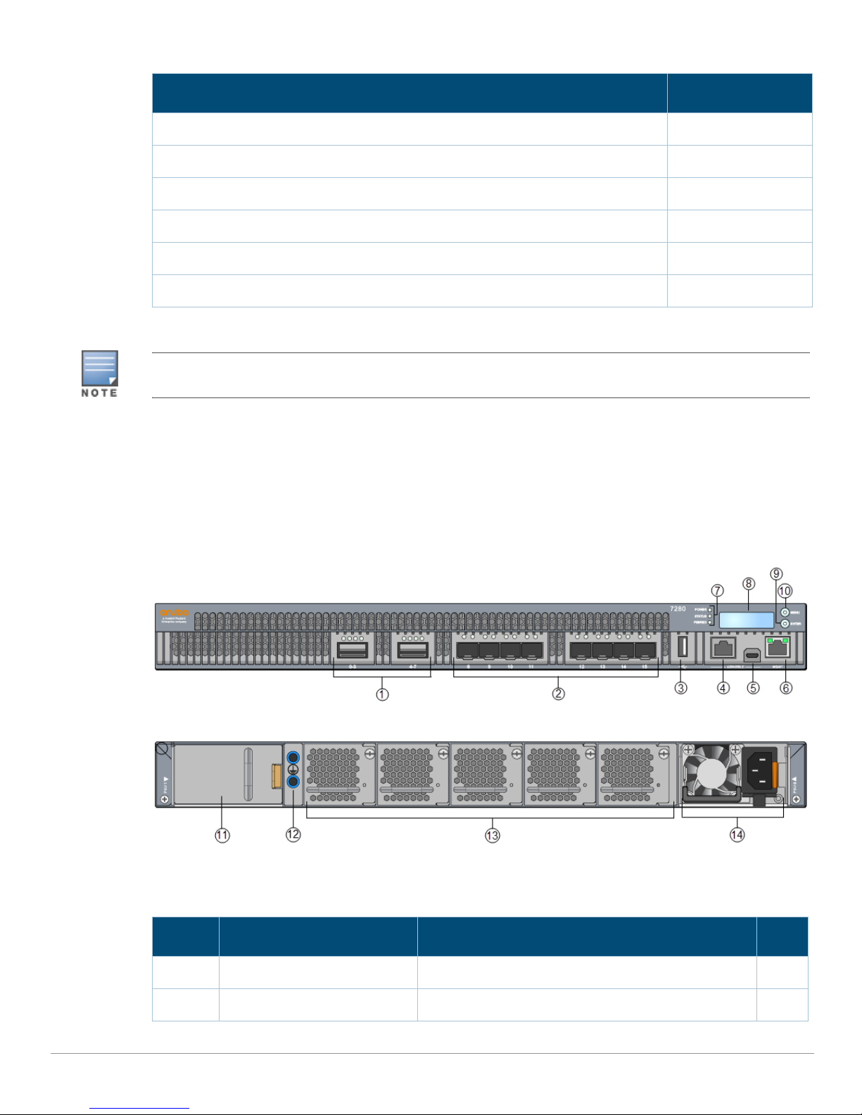
Table 3 Package Contents (Continued)
Item Quantity
M6 x 7 mm Grounding Screws 2
Power Cable 1
Micro-USB Cable 1
Rubber Feet 4
Aruba 7280 Start-up Guide (Printed) 1
End User License Agreement (Printed) 1
Optional accessories are available for use with the Aruba 7280 controller and are sold separately. Contact your
Aruba sales representative for details and assistance.
7280 Controller Components
This section introduces the component and its location in the Aruba 7280 controller.
Figure 1 shows the front panel of the Aruba 7280 controller and Figure 2 shows the back panel of the
Aruba 7280 controller.
Figure 1 Front Panel of the Aruba 7280 Controller
Figure 2 Back Panel of the Aruba 7280 Controller
The following table lists the components on the Aruba 7280 controller:
Table 4 Aruba 7280 Controller Components
Callout Component Description Page
1 40 GbE QSFP+ Ports 2 x 40 GbE QSFP+ ports 9
2 10GBase-X (SFP+) Ports 8 x 10GBase-X (SFP+) Ports 10
8 | 7280 Controller Aruba 7280 Controller | Installation Guide
Page 9
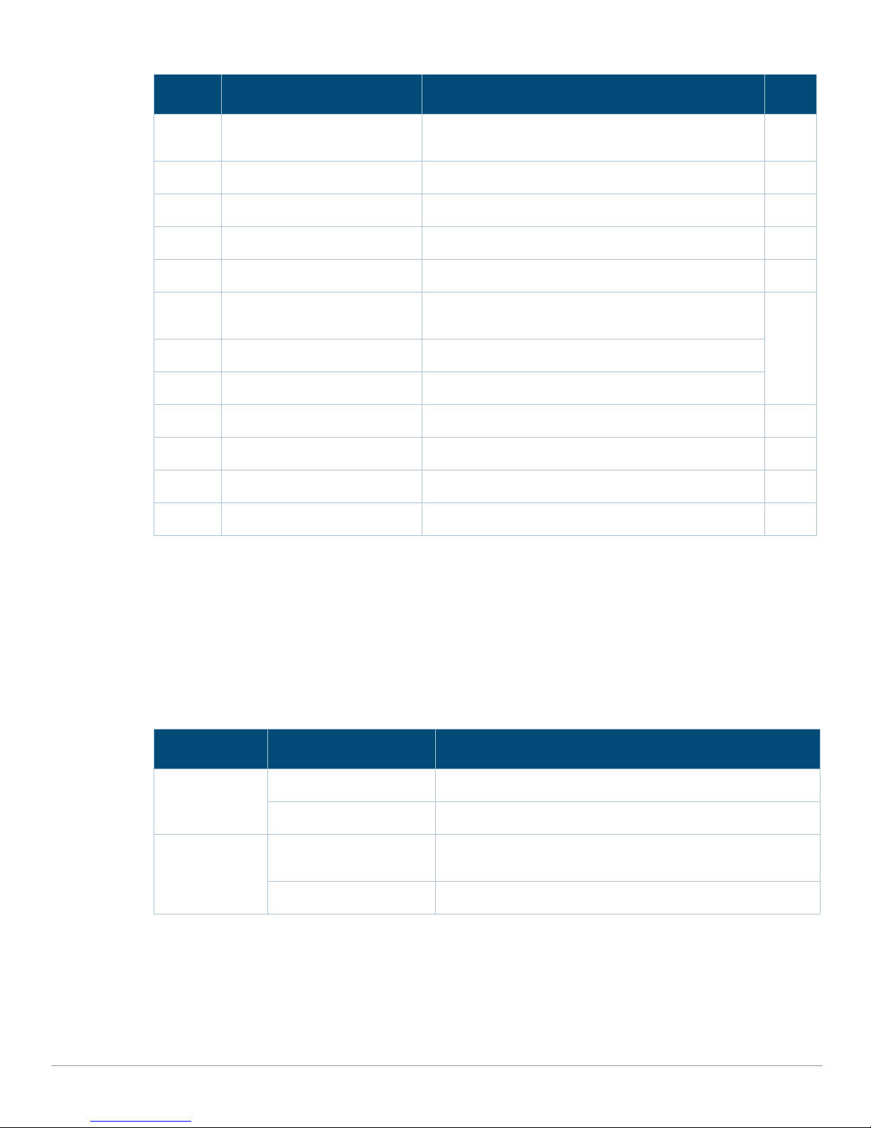
Table 4 Aruba 7280 Controller Components (Continued)
Callout Component Description Page
3 USB Interface USB storage device can be used to save and upload
configurations
4 Console Port RJ-45 serial console access port 12
5 Micro USB Console Port Provides console access for direct local access 13
6 Management Port Used to connect to a separate management network 13
7 Power, Status, and Peered LEDs Used for basic monitoring of the Aruba 7280 controller 14
8 LCD Used to configure LED behavior and other basic
operations
9 Enter Button Used to execute actions on the LCD screen
10 Menu Button Used to select the LCD screen menu
11 PSU Slot 1 Slot for additional power supply module 16
12 Grounding Points Used to attach the grounding screws 16
13 Fans 5 x hot-swappable high speed fans 16
14 PSU Slot 0 Primary power supply module 17
12
14
40 GbE QSFP+ Ports
The Aruba 7280 controller includes two 40 GbE QSFP+ ports labeled 0-3 and 4-7. It is recommended
to use Aruba supported QSFP+ transceivers in these ports.
Each 40 GbE QSFP+ port is equipped with four Link LEDs above the port allowing you to monitor the
status on the port. These ports also support 40G split cable (4 x 10G).
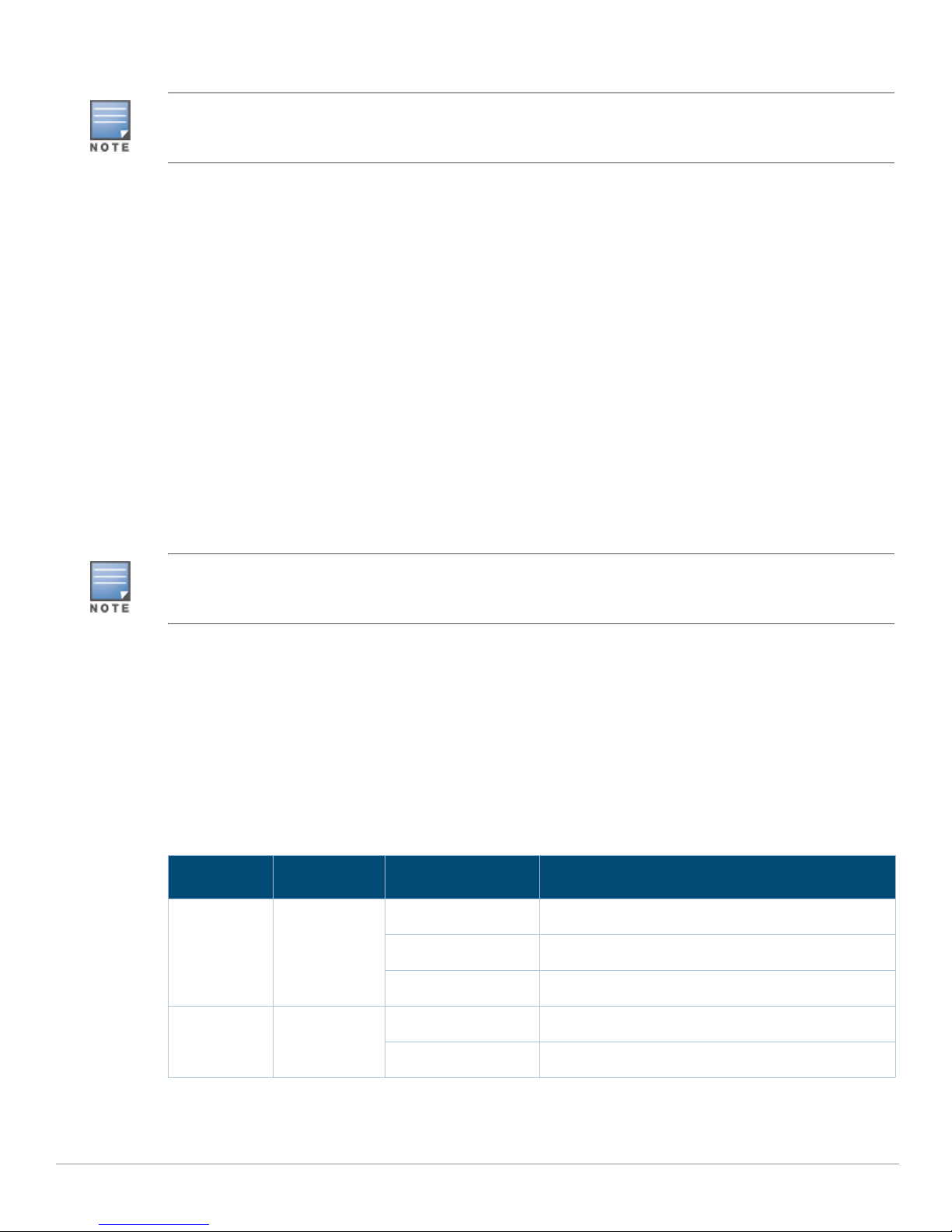
The following table describes the Link LED behavior for each mode:
Table 5 40 GbE QSFP+ Port LEDs
Mode Indicator Status
40 G Amber (Solid) 40 G link is established
Off No link
4 x 10 G Green (Solid) 4 x 10 G port link is established (using 40 G to 4 x 10G splitter
cable)
Off No link
Supported QSFP+ Modules and DAC Cables
QSFP+ modules are a compact, hot-pluggable transceiver used for data communications
applications. It interfaces networking hardware to a fiber optic cable or active or passive electrical
copper connection to other devices.
Aruba 7280 Controller | Installation Guide 7280 Controller | 9
Page 10
Direct attach cables (DACs) are installed in an uplink port in the same manner as an QSFP+ module.
Aruba tests and supports Aruba optics within their controller systems. Third party optics are not tested or
supported; therefore, Aruba does not guarantee proper functionality of third party optics when used in an
Aruba system.
Following is the list of QSFP+ modules and DAC cables supported in 7280 controllers:
QSFP+ modules:
JH231A— HPE X142 40G QSFP+ MPO SR4 Transceiver
JH232A— HPE X142 40G QSFP+ LC LR4 SM Transceiver
JH233A— HPE X142 40G QSFP+ MPO eSR4 300M Transceiver
DAC cables:
JH234A— HPE X242 40G QSFP+ to QSFP+ 1m Direct Attach Copper Cable
JH235A— HPE X242 40G QSFP+ to QSFP+ 3m Direct Attach Copper Cable
JH236A— HPE X242 40G QSFP+ to QSFP+ 5m Direct Attach Copper Cable
10GBase-X (SFP+) Ports
The 7280 controller is equipped with eight 10GBase-X (SFP+) ports. These port are labeled as 8 to 15.
These ports are intended for use with Aruba SFP/SFP+. These ports support dual speed (1GbE or
10GbE) operation.
Aruba tests and supports Aruba optics within their controller systems. Third party optics are not tested or
supported; therefore, Aruba does not guarantee proper functionality of third party optics when used in an
Aruba system.
Each 10GBase-X port is equipped two LEDs that allow you to monitor the status of and activity on the
port. These LEDs provide basic monitoring of the status, activity, and basic configuration of each port.
The information displayed by these LEDs can be changed via LCD.
LINK/ACT: Placed on the left side of the port, and displays the link status and activity of the port.
STATUS: Placed on the right side of the port, and displays the status of the port based on the
information displayed by this LED changes based on LCD’s mode.
The following table describes the LED behavior for each mode:
Table 6 10GBase-X Port LEDs
LED Function Indicator Status
LINK/ACT Link status Green (Solid) Link established
Green (Blinking) Port is transmitting or receiving data
Off No link
STATUS Port status Green (Solid) Link at 10 Gbps
10 | 7280 Controller Aruba 7280 Controller | Installation Guide
Off Link at 1 Gbps
Page 11
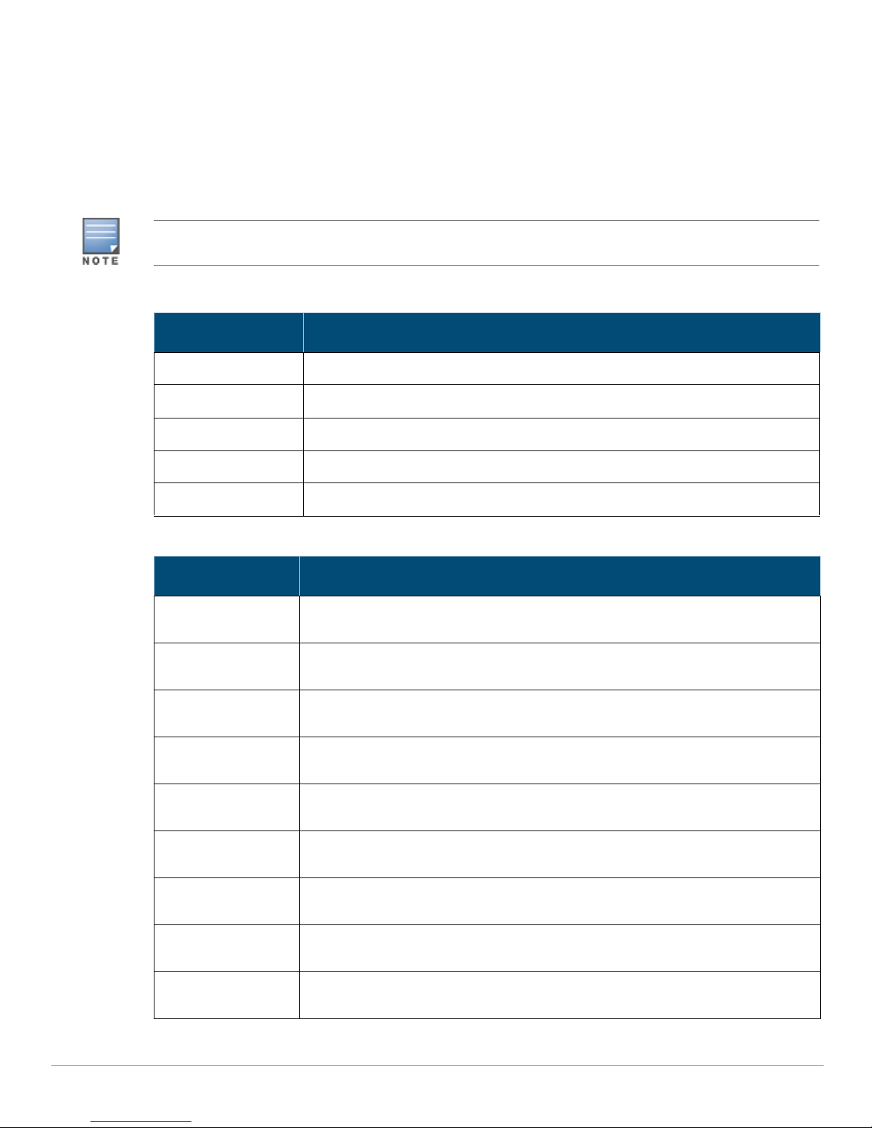
Supported SFP/SFP+ Modules and DAC Cables
SFP/SFP+ modules, also known as mini-GBICs, are hot-swappable and provide optical or copper
connections to other devices.
Direct attach cables (DACs) are installed in an uplink port in the same manner as an SFP/SFP+
module.
For the list of Aruba approved DAC cables and SFP/SFP+ modules for controllers, see Table 7 and
Table 8.
Other non-approved third-party optics or DAC cables are not tested or supported by Aruba on controllers;
therefore, Aruba does not guarantee their proper functionality when used with Aruba controllers.
Table 7 Supported DAC Cables
DAC Description
DAC-SFP-10GE-50CM 50cm Direct Attach Cable; 10G SFP+
DAC-SFP-10GE-1M 1m Direct Attach Cable; 10G SFP+
DAC-SFP-10GE-3M 3m Direct Attach Cable; 10G SFP+
DAC-SFP-10GE-5M 5m Direct Attach Cable; 10G SFP+
DAC-SFP-10GE-7M 7m Direct Attach Cable; 10G SFP+
Table 8 Supported SFP/SFP+ Modules
SFP/SFP+ Description
SFP-SX SFP, 1000BASE-SX, LC Connector; 850nm pluggable GbE optic; up to 300 meters over
SFP-LX SFP, 1000BASE-LX, LC Connector; 310nm pluggable GbE optic; up to 10,000 meters
SFP-TX SFP, 1000BASE-T SFP; copper GbE pluggable; RJ45 connector; up to 100 meters over
SFP-EX 1000BASE-ZX SFP; 1310nm pluggable GbE optic; LC connector; up to 40,000 meters
SFP-ZX 1000BASE-ZX SFP; 1310nm pluggable GbE optic; LC connector; up to 70,000 meters
SFP-10G-SR SFP+, 10GBASE-SR, 850nm serial pluggable SFP+ optic, target range 300m over MMF,
SFP-10G-LR SFP+, 10GBASE-LR, 1310nm serial pluggable SFP+ optic for up to 10km over SMF, LC
multi-mode fiber (Type OM2).
over single-mode fiber.
Category-5, 5e, 6 and 6a unshielded twisted pair cable.
over single mode fiber.
over single mode fiber
LC Connector
Connector
SFP-10G-LRM SFP+, 10GBASE-LRM, 1310nm serial pluggable SFP+ optic, long-reach multi mode, LC
SFP-10G-ER SFP+, 10GBASE-ER, 1310nm pluggable 10GE optic; up to 40,000 meters over single-
Aruba 7280 Controller | Installation Guide 7280 Controller | 11
connector
mode fiber, LC connector
Page 12
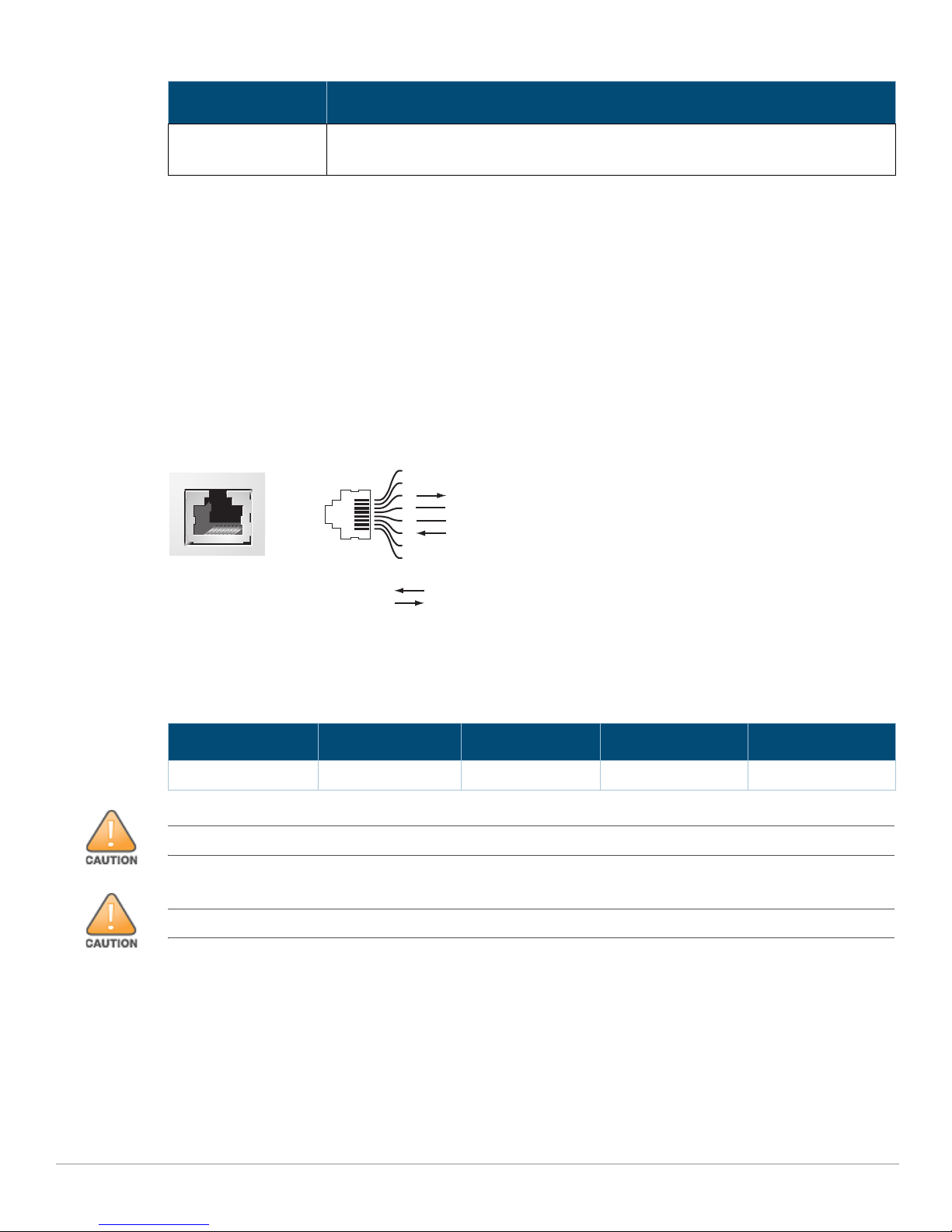
Table 8 Supported SFP/SFP+ Modules
Serial
Console Port
1
2
3
4
5
6
7
8
TxD
GND
RxD
RJ-45 Female
Pin-Out
Direction
Input
Output
GND
SFP/SFP+ Description
SFP-10G-ZR SFP+, 10GBASE-ZR, 1310nm pluggable 10GE optic; up to 70,000 meters over single-
mode fiber, LC connector
USB Interface
The Aruba 7280 controller is equipped with a USB 2.0 interface. See Figure 5 on page 14. A USB
storage device can be used to save and upload configurations to the controller. USB functions are
controlled through the LCD panel on the front of the controller. For more information on the LCD
panel and its functions, see “LCD Panel” on page14.
Console Port
Use the serial CONSOLE port to allow direct local management. See Figure 5 on page 14. This port is a
RJ-45 female connector that accepts an RS-232 serial cable with a male connector.
Figure 3 Serial Console Port Pin-Out
The communication settings for the Console port is shown in the following table:
Table 9 Console Terminal Settings
Baud Rate Data Bits Parity Stop Bits Flow Control
9600 8 None 1 None
The CONSOLE port is compatible only with RS-232 devices. Non-RS-232 devices, such as APs, are not supported.
Do not connect the Console port to an Ethernet switch or a PoE power source. This may damage the controller.
12 | 7280 Controller Aruba 7280 Controller | Installation Guide
Page 13
Serial Console Port Adapter
3
4
5
2
5
63
RJ-45 DB-9
Internal
Connections
TxD
GND
RxD
1
2
3
4
5
6
7
8
TxD
GND
RxD
RJ-45 Female
Pin-Out
DB-9 Male
Pin-Out
TxD
RxD
Ground
5
4
3
2
1
9
8
7
6
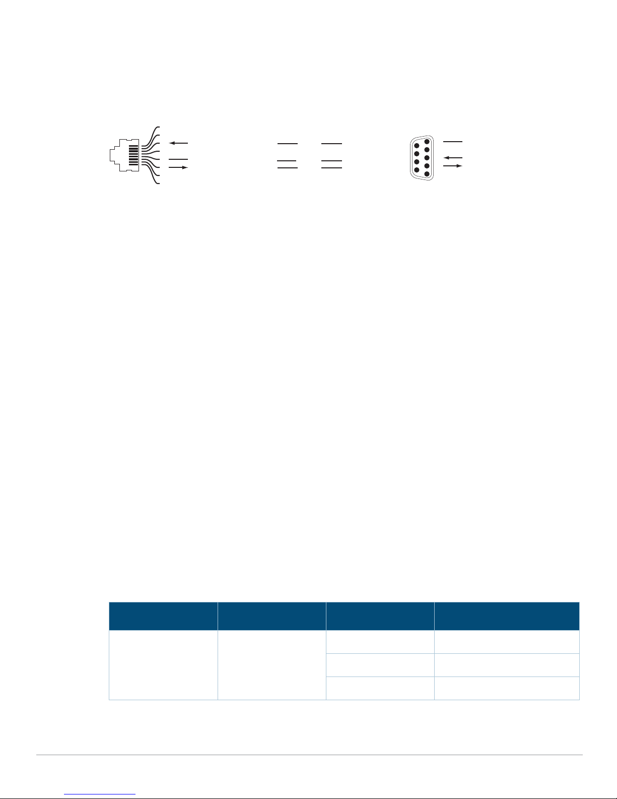
A modular adapter can be used to convert the female RJ-45 connector to a male DB9 connector. See
Figure 4 for complete details.
Figure 4 RJ-45 (Female) to DB9 (Male) Modular Adapter Conversion
Micro USB Console Connector
The Aruba 7280 controller is equipped with a micro USB (type B) connector that provides console
access for direct local access. See Figure 5 on page 14. If both micro USB and RJ-45 console ports are
connected, the micro USB connection takes precedence over the RJ-45 console connection.
Micro USB Driver
To use the micro USB console port, you must install the Aruba micro USB driver on the computer that
will manage your controller. To download the driver, perform the following steps:
1. Go to https://support.arubanetworks.com.
2. Click on the Tools & Resources tab.
3. Open the USB Console Driver folder.
4. Open the Mobility Controller and Mobility Access Switch folder.
5. Select the appropriate file for your application. The corresponding operating system is in the file
name.
Management Port
The Aruba 7280 controller is equipped with a 10/100/1000BASE-T Gigabit Management (RJ-45) port.
See Figure 5 on page 14.
The management port provides 10/100/1000 Mbps Ethernet access to the Aruba 7280 controller CLI,
SNMP, and Web interface for complete system management and troubleshooting. It can also be used
to connect to a separate management network.
The management port has an LINK/ACT LED on its left side and SPEED LED on its right side. During
operation, these LEDs provide status information as shown in the following table:
Table 10 10/100/1000BASE-T (RJ-45) Management Port
LED Function Indicator Status
LINK/ACT Link Status Information Green (Solid) Link has been established
Aruba 7280 Controller | Installation Guide 7280 Controller | 13
Green (Blinking) Link activity
Off No link on port
Page 14
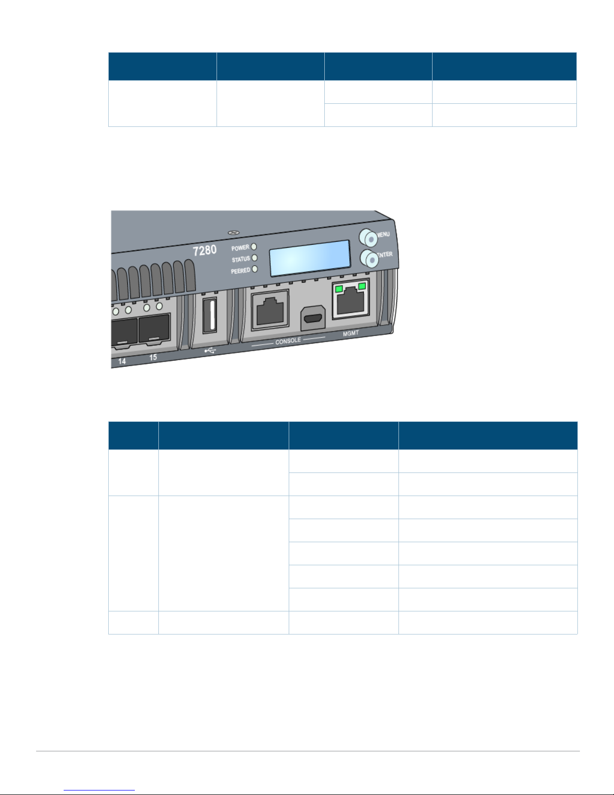
Table 10 10/100/1000BASE-T (RJ-45) Management Port (Continued)
LED Function Indicator Status
SPEED Interface Speed Green (Solid) 1000 Mbps
Off 10/100 Mbps
Power, Status, and Peered LEDs
The front panel also includes power, status, and peered LEDs that provide basic monitoring of the
overall status of the Aruba 7280 controller. See Figure 5.
Figure 5 Ports, LEDs, and LCD Panel
The following table show the LED indicators and the corresponding status:
Table 11 Power, Status, and Peered LEDs
LED Function Indicator Status
Power System powers Green (Solid) Power On
Off Power Off
Status System status Green (Solid) Operational
Green (Blinking) Device is loading software
Amber (Blinking) Major alarm
Amber (Solid) Critical alarm
Off No power
Peered Reserved for future use N/A N/A
LCD Panel
The Aruba 7280 controller is equipped with an LCD panel (see Figure 5 on page 14.) that displays
information about the controller’s status and provides a menu that allows basic operations such as
initial setup and reboot. The LCD panel displays two lines of text with a maximum of 16 characters on
each line. When using the LCD panel, the active line is indicated by an arrow next to the first letter.
14 | 7280 Controller Aruba 7280 Controller | Installation Guide
Page 15
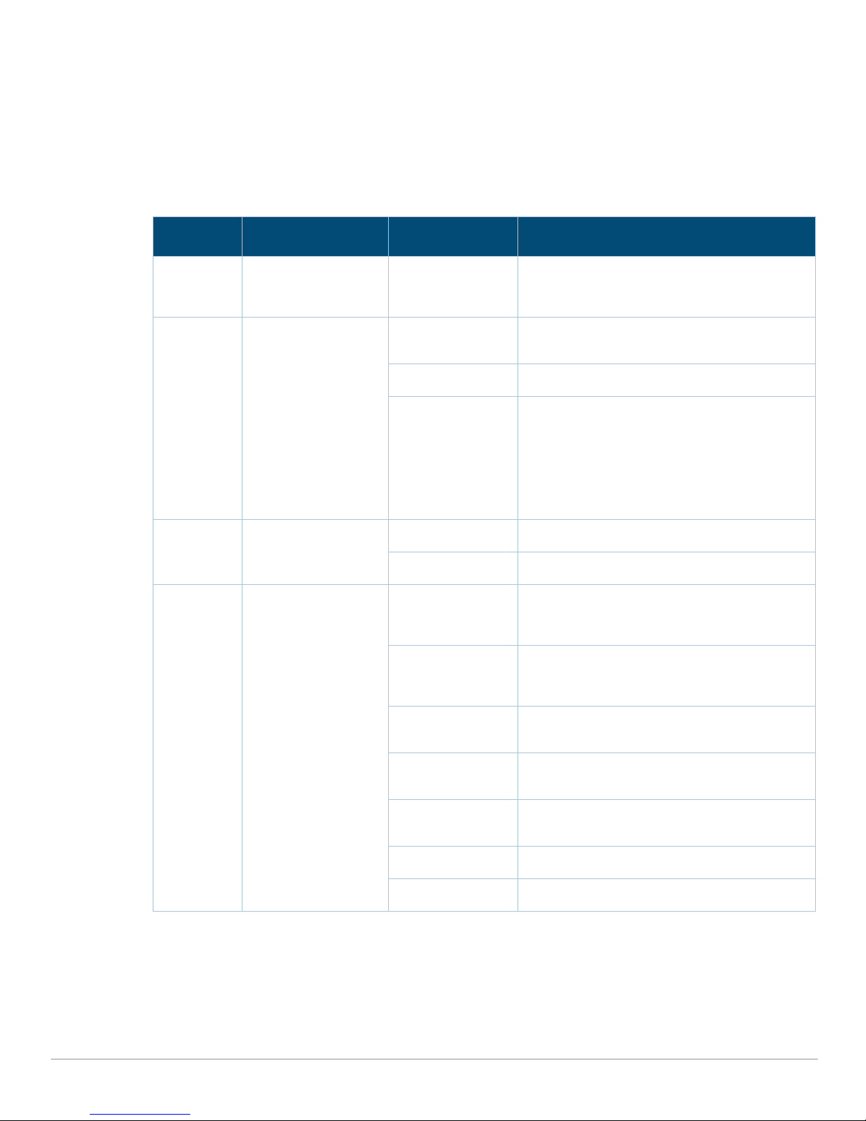
The LCD panel is operated using the two navigation buttons to the right of the screen.
Menu: Allows you to navigate through the menus of the LCD panel.
Enter: Confirms and executes the action currently displayed on the LCD panel.
LCD Mode Menu
The LCD mode menu includes four modes as shown in the following table.
Table 12 LCD Panel Mode
LCD Mode Function Displays Description
Boot Displays the boot
status of the
controller.
LED Displays the mode of
the STATUS LED of
ports. The LED mode
menu allows to
choose what
information is
communicated by the
STATUS LEDs on each
port. See Tab le 6 on
page 10 for
descriptions of the
LED behavior of each
mode.
Status Displays the ArubaOS
version.
Maintenance Allows execution of
some basic operations
such as uploading an
image or rebooting the
controller
“Booting ArubaOS... Boot status of the controller
LED mode: ADM Administrative– Displays whether the port is
administratively enabled or disabled
LED mode: SPD Speed– Displays the speed of the port
Exit Exit LED menu
OS Version ArubaOS version
Exit Exit Status menu
Upgrade Image
[Partition 0 [Y|N] |
Partition 1 [Y|N]]
Upload config [Y | N]Upload the controller’s current configuration to
Upgrade the controller image on the selected
partition from a predefined location on an
attached USB flash device
a predefined location on the attached USB flash
device
Disabling the LCD Screen
By default, the LCD screen is enabled. However, if the 7280 controller is deployed in a location
without physical security, the LCD screen can be disabled through the CLI. When disabled, pushing
one of the navigation buttons will only illuminate the LCD screen and display the slot, role, device
name, and any alarms.
Aruba 7280 Controller | Installation Guide 7280 Controller | 15
Factory Default
[Y|N]
Media Eject [Y| N] Complete reading or writing to the attached USB
Reload system
[Y|N]
Halt system [Y|N] Halt controller
Exit Exit Maintenance menu
Reset the device to factory default settings
device
Reload controller
Page 16
Additionally, it is possible to disable only the maintenance menu. This allows you to change the LED
behavior and view the device status but prevent upgrades and configuration changes.
To disable the LCD screen, enter the Enable mode and use the following CLI commands:
(host) #configure terminal
(host) (config) #lcd-menu
(host) (lcd-menu) #disable menu
To disable only the Maintenance menu or one of its sub-menus, enter the Enable mode and use the
following CLI commands:
(host) #configure terminal
(host) (config) #lcd
(host) (lcd-menu) #disable menu maintenance ?
factory-default
halt-system
media-eject
reload-system
upgrade-image
upload-config
(host) (lcd-menu) #disable menu maintenance upgrade-image ?
partition0
partition1
PSU Slot 1
The Aruba 7280 controller includes a PSU slot 1 that has a filler panel covering the opening. PSU slot
1 is for an additional power supply module that may be required for redundancy. PSU slot 1 can hold
the same power supply module as PSU slot 0. For more details, see “PSU Slot 0” on page17.
Grounding Point
To meet safety and electromagnetic interference (EMI) requirements and to ensure proper
operation, the controller must be adequately grounded before power is connected. Connect a
grounding cable to earth ground and then attach it to the chassis grounding point using two screws.
Comply with electrical grounding standards during all phases of installation and operation of the
product. Do not allow the controller’s chassis, network ports, power supply, or mounting brackets to
contact any device, cable, object, or person attached to a different electrical ground. Also, never
connect the device to external storm grounding sources.
Fan Module
The Aruba 7280 controller is equipped with five field-replaceable, hot-swappable fan modules. Each
fan module features a fan that pull air through the chassis from the front through to the rear. The
7280 controller can tolerate the failure of a single fan while maintaining a safe operating temperature
for the controller.
The 7280 controller is not compatible with fan modules from other Aruba hardware platforms.
The LED behavior in the fan module is as follows:
Green - Fan module is operational
Amber - Fan module is faulty
16 | 7280 Controller Aruba 7280 Controller | Installation Guide
Page 17
Hot Swapping
Hot swapping allows you to replace a failed fan module, making it unnecessary to shut down the
7280 controller during the replacement procedure.
PSU Slot 0
The Aruba 7280 controller is equipped with a 550W power supply, which is an autosensing, loadsharing, redundant power supply module that supports an input voltage of 100 VAC to 240 VAC. Each
power supply has a country-specific power cord for connection to an AC power outlet.
The Aruba 7280 controller is shipped with one hot-swappable, field-replaceable, AC power supply in
PSU slot 0 and one filler panel in PSU slot 1. The controller can operate with one or two active power
supplies, depending on the demands of your configuration. The following sections describe features
of the 550W AC power supply:
Load Sharing
Load sharing occurs when more than one power supply of the same rating is installed in the 7280
controller and turned on. Load sharing divides the total power load of the controller among all
available power supplies. Since the power supplies work together, the effective power capacity of the
controller is increased with each additional power supply.
Redundancy
With power redundancy, the 7280 controller can continue normal operation even when a power
supply fails or is turned off. When multiple power supplies are installed, if one becomes unavailable
(fails, or is turned off or removed) the remaining power supplies will attempt to provide full power for
the device. If the device’s total power load does not exceed the combined rated output of the
remaining, operational power supplies, the controller will continue to operate.
Hot Swapping
Hot swapping allows you to replace one failed power supply while the others provide full power. This
makes it unnecessary to shut down the 7280 controller during the replacement procedure.
Hot swapping is supported only when power redundancy is in effect. This requires that after the
target power supply is removed, the device’s total power load does not exceed the combined rated
output of the remaining power supplies.
Never insert or remove the a power supply module while the power cord is connected to it. Verify that cord has
been disconnected from the power supply before installation or removal.
LED Indicators
The following table shows the LED indicators and the corresponding status:
Table 13 Power Supply Module LED
Indicator Status
Green (Solid) Power supply is operational.
Green (blinking) at 1 Hz Power supply is in standby.
Green (blinking) at 0.5 Hz Power cord is unplugged from one power supply and plugged in
the other power supply.
Amber (Solid) Fan module faulty or in protection.
Aruba 7280 Controller | Installation Guide 7280 Controller | 17
Page 18
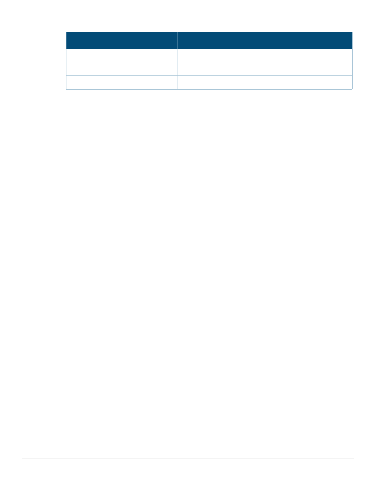
Table 13 Power Supply Module LED (Continued)
Indicator Status
Amber (blinking) at 1 Hz Warning! Power supply module can operate normally but high
temperature without protection, fan speed slow down, voltage
lower, high power, and high current.
Off No power.
18 | 7280 Controller Aruba 7280 Controller | Installation Guide
Page 19
Chapter 2
Installation
Installation of the device should be performed by a trained installation professional.
This chapter describes how to install an Aruba 7280 controller using the many mounting options
available. The 7280 controller ships with an accessory kit that includes the equipment needed to
install the controller in standard, 19-inch telco rack.
“Precautions” on page19
“Selecting a Location” on page20
“Rack Mounting- Standard” on page20
“Rack Mount Installation- Mid” on page22
“Table or Shelf Installation” on page23
“Wall Mounting” on page23
“Connecting and Disconnecting the AC Power Cord” on page25
“Removing and Installing a Fan Module” on page26
“Installing and Removing a Power Supply Module” on page27
“Installing an SFP/SFP+/QSFP+/LC Cable” on page27
Please only use the included or Aruba specified cables, power cords, AC power supplies, and batteries. The
power cord should not be used with other electric equipment than what is specified by Aruba.
接続ケーブル、電源コード、AC アダプタ、バッテリーなどの部品は、必ず添付品または指定品をご使用ください。
また、電源ケーブルは弊社が指定する製品以外の電気機器には使用できないためご注意ください。
Precautions
Ensure that the rack is correctly and securely installed to prevent it from falling or becoming
unstable.
Dangerous voltage above 240VAC is always present while the Aruba Power Supply Module is
plugged into an electrical outlet. Remove all rings, jewelry, and other potentially conductive
material before working with this device.
Never insert foreign objects into the chassis, power supply, or any other component, even when
the power supply is turned Off, unplugged, or removed.
Ensure that the main power is fully disconnected from the controller by unplugging all power
cords from their outlets. For safety, verify that the power outlets and plugs are easily reachable by
the operator.
Do not handle electrical cables which are not insulated. This also includes network cables.
Keep water and other fluids away from the controller to minimize electrical hazards.
Aruba 7280 Controller | Installation Guide Installation | 19
Page 20
Comply with electrical grounding standards during all phases of installation and operation of the
product. Do not allow the controller’s chassis, network ports, power supply, or mounting brackets
to contact any device, cable, object, or person attached to a different electrical ground. Also, never
connect the device to external storm grounding sources.
Perform installation or removal of the chassis or any module in a static-free environment. Proper
use of anti-static body straps and mats is strongly recommended.
Modules must be kept in anti-static packaging when not installed in the chassis.
Do not ship or store this product near strong electromagnetic, electrostatic, magnetic, or
radioactive fields.
Do not disassemble the chassis.
Selecting a Location
The 7280 controller, like other network and computing devices, requires the following “electronicfriendly” environment:
Reliable power
Verify that your electrical outlet is compatible with the 7280 controller power supply.
Cool, non-condensing ventilation
For proper operation, the 7280 controller requires an environment with an ambient air
temperature between 0º C and 40º C (32º F and 104º F). Humidity must be kept at non-condensing
levels, between 10% and 90%.
Where a large number of electrical devices are working in the same area, additional air
conditioning or air circulation equipment may be required.
Ample space
For proper air circulation, leave at least 10 cm (4 inches) clearance all around the chassis.
Leave additional space in front and rear side of the chassis to access power cords, network cables,
and indicator LEDs.
Limited electromagnetic interference
For best operation, keep the 7280 controller and all cords and cables at least 0.7 meters (2 feet)
from fluorescent lighting fixtures, and 2 meters (6 feet) from photocopiers, radio transmitters,
electric generators, and other sources of strong electromagnetic interference.
Rack Mounting- Standard
This mounting option allows mounting the 7280 controller in a two-post 19-inch Telco rack.
Each 7280 controller should have its own mounting equipment. Do not place other networking equipment
directly on top of a mounted 7280 controller. Failure to do so can damage the device.
Required Tools and Equipment
The following tools and equipment are required for installing a 7280 controller:
Mounting Bracket (x2) (included in the kit): Do not use for table or shelf installation
Screws for mounting bracket (x8): M4 x 8 mm Phillips Flat Head Screws (included in the kit)
Screws for system rack mount (x4): M6 x 15 mm Phillips Pan Head Screws (included in the kit)
20 |Installation Aruba 7280 Controller | Installation Guide
Page 21
Suitable Screwdrivers for all screw types provided in the box (not included in the kit)
Some racks require screws that differ from those included with the 7280 controller. Ensure that you have the
correct screws before installing the 7280 controller.
Installation Steps
To install a 7280 controller into a two-post 19-inch Telco rack:
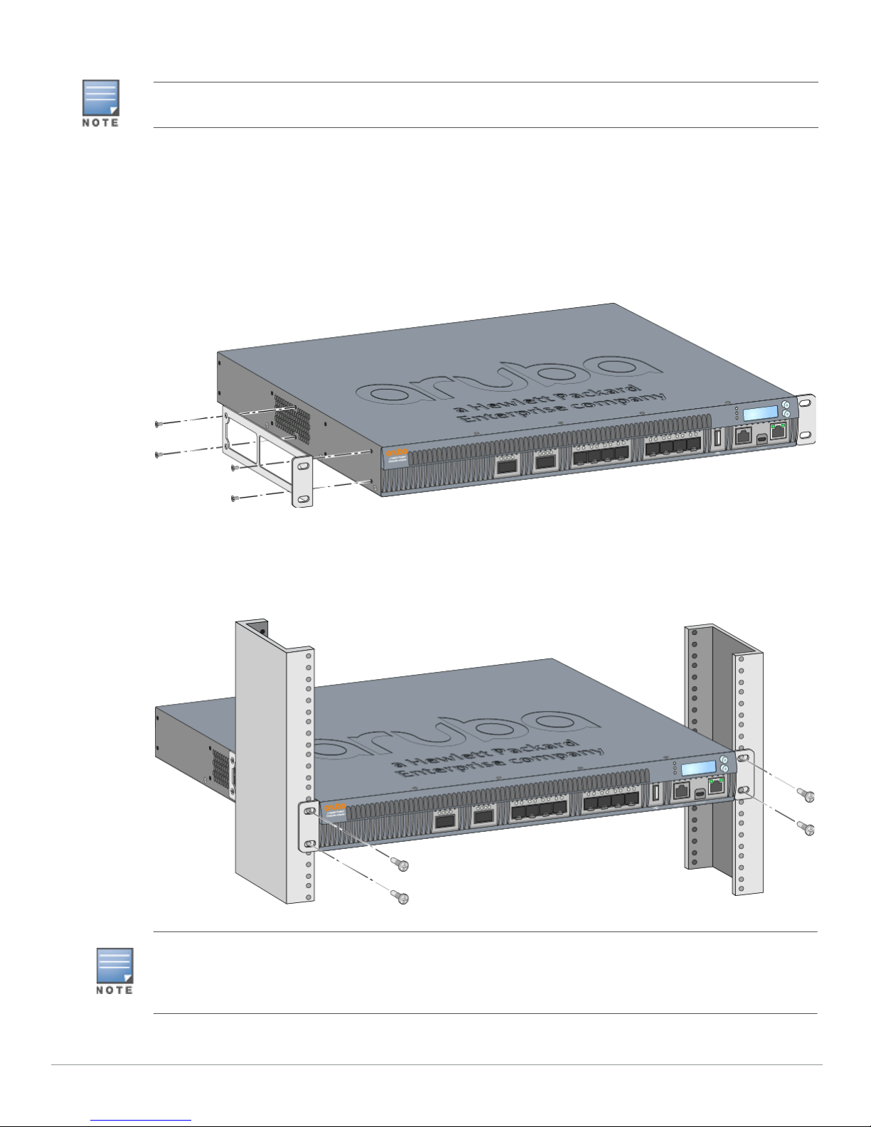
1. Place the mounting bracket over the mounting holes on the controller (see Figure 6).
2. Secure the bracket to the controller using the eight screws for the mount bracket (four per
bracket) and a suitable screwdriver.
Figure 6 Rack Mount Brackets
3. Mount the controller within your organization’s rack system using the four screws for system rack
mount (two per bracket) and a suitable screwdriver (see Figure 7).
Figure 7 Rack Mount Installation
Leave a minimum of 10 cm (4 inches) of space on the left and right side of the controller for proper air flow
and ventilation.
Leave additional space in the front and the back of the controller to access network cables, LED status
indicators, and power cord.
Aruba 7280 Controller | Installation Guide Installation | 21
Page 22
Rack Mount Installation- Mid
This mounting option allows mounting the 7280 controller from the middle in standard two-post 19inch Telco rack. The mounting brackets can be used for this installation as well.
Each 7280 controller should have its own mounting equipment. Do not place other networking equipment
directly on top of a mounted 7280 controller. Failure to do so can damage the device.
Required Tools and Equipment
The following tools and equipment are required for installing a 7280 controller:
Mounting Bracket (x2) (included in the kit)
Screws for mounting bracket (x8): M4 x 8 mm Phillips Flat Head Screws (included in the kit)
Screws for system rack mount (x4): M6 x 15 mm Phillips Pan Head Screws (included in the kit)
Suitable Screwdrivers for all screw types provided in the box (not included in the kit)
Some racks require screws that differ from those included with the 7280 controller. Ensure that you have the
correct screws before installing the 7280 controller.
Installation Steps
To install a 7280 controller from the middle in a standard two-point 19-inch Telco rack:
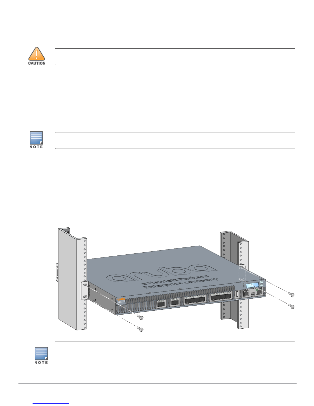
1. Place the mounting bracket over the mounting holes on either side of the controller in the middle.
2. Secure the bracket to the controller using the eight screws for the mount bracket (four per
bracket) and a suitable screwdriver.
3. Mount the controller within your organization’s rack system using the four screws for system rack
mount (two per bracket) and a suitable screwdriver (see Figure 8).
Figure 8 Rack Mount Installation- Mid
Leave a minimum of 10 cm (4 inches) of space on the left and right side of the controller for proper air flow
and ventilation.
Leave additional space in the front and the back of the controller to access network cables, LED status
indicators, and power cord.
22 |Installation Aruba 7280 Controller | Installation Guide
Page 23
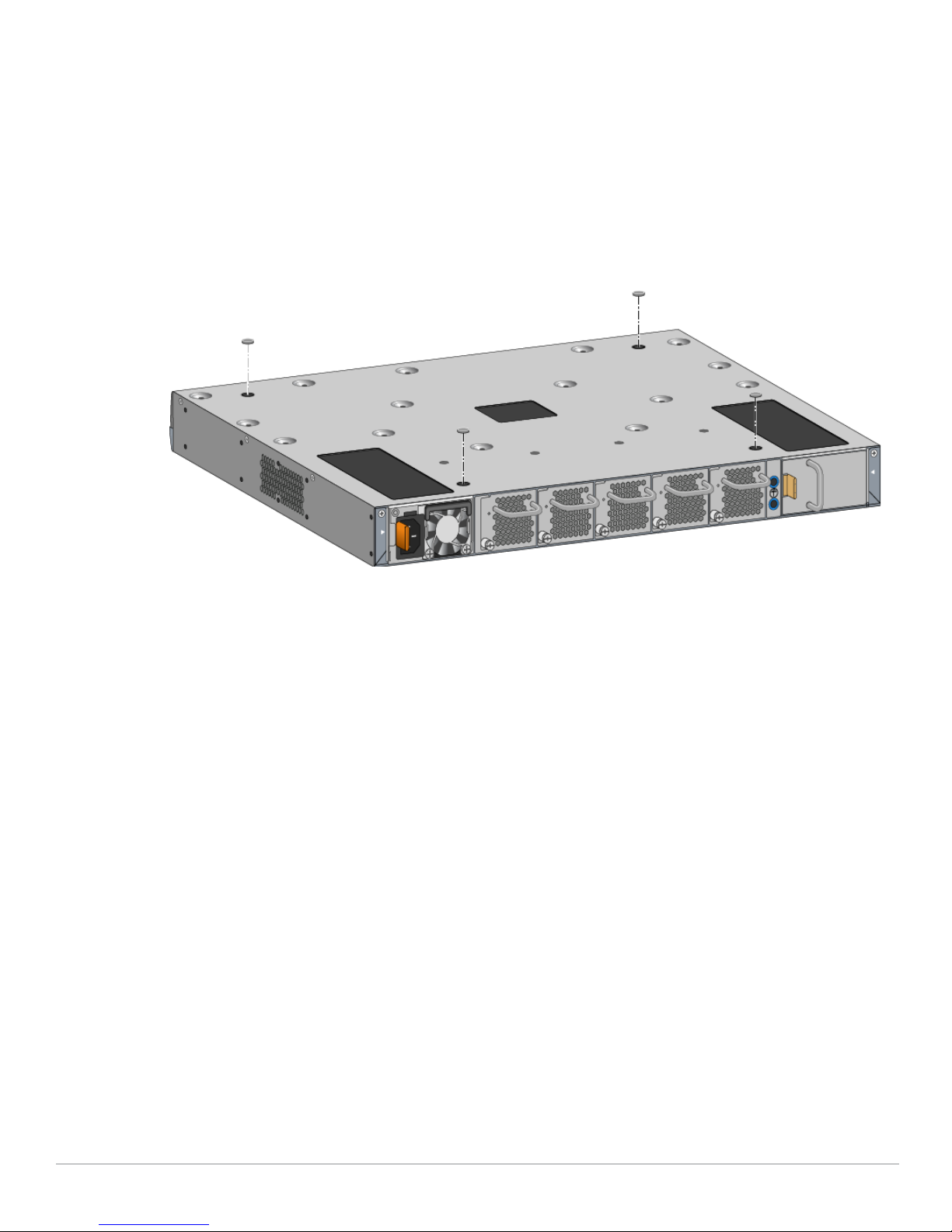
Table or Shelf Installation
This mounting option allows mounting the 7280 controller on a table or shelf.
Required Tools and Equipment
Rubber Feet (included in the kit)
Installation Steps
1. Attach the rubber feet to the bottom of the controller (see Figure 9).
Figure 9 Attaching Rubber Feet
2. Place the controller in the location you have chosen.
Wall Mounting
An optional accessory kit (must be purchased separately) is available that allows you to mount the
7280 controller to a wall. For more information about this accessory kit, contact your Aruba sales.
representative.
Required Tools and Equipment
The following tools and equipment are required for installing a 7280 controller on a wall:
Mounting Brackets (x2) (included in the mounting accessory kit))
Screws for mounting bracket (x8): M4 x 8 mm Phillips Flat Head Screws (included in the kit)
Wall Anchors: Optional accessory (not included in the kit)
Wall Mounting Screws: The type of screw depends on the installation surface (not included in the
kit)
Suitable Screwdrivers for all screw types (not included in the kit)
Aruba 7280 Controller | Installation Guide Installation | 23
Page 24
Installation Steps
To install a 7280 controller on a wall:
Ensure that the Ethernet ports are facing down when installing the 7280 controller on a wall.
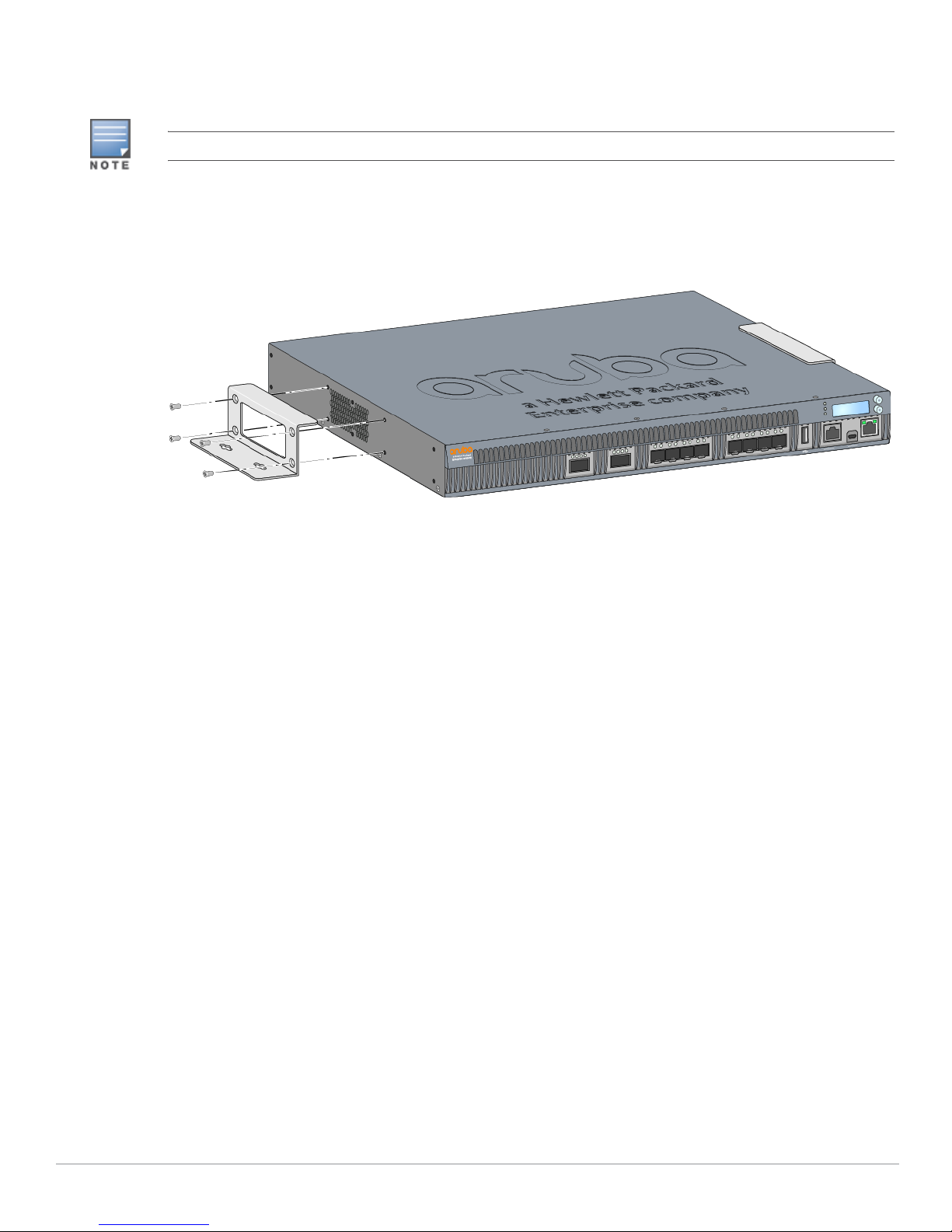
1. Fasten the mounting brackets over the mounting holes on the sides of the 7280 controller using
the eight screws for mounting bracket (four per bracket) and a suitable screwdriver (see Figure
10).
Figure 10 Attaching the Wall Mount Brackets
2. After you have chosen a mounting location, mark the locations on the wall where you intend to
make mounting holes.
3. Create the holes and insert wall anchors if your installation requires them.
4. Align the mounting bracket holes with the holes you created in the wall (see Figure 11).
5. Use appropriate screws to secure the 7280 controller.
24 |Installation Aruba 7280 Controller | Installation Guide
Page 25
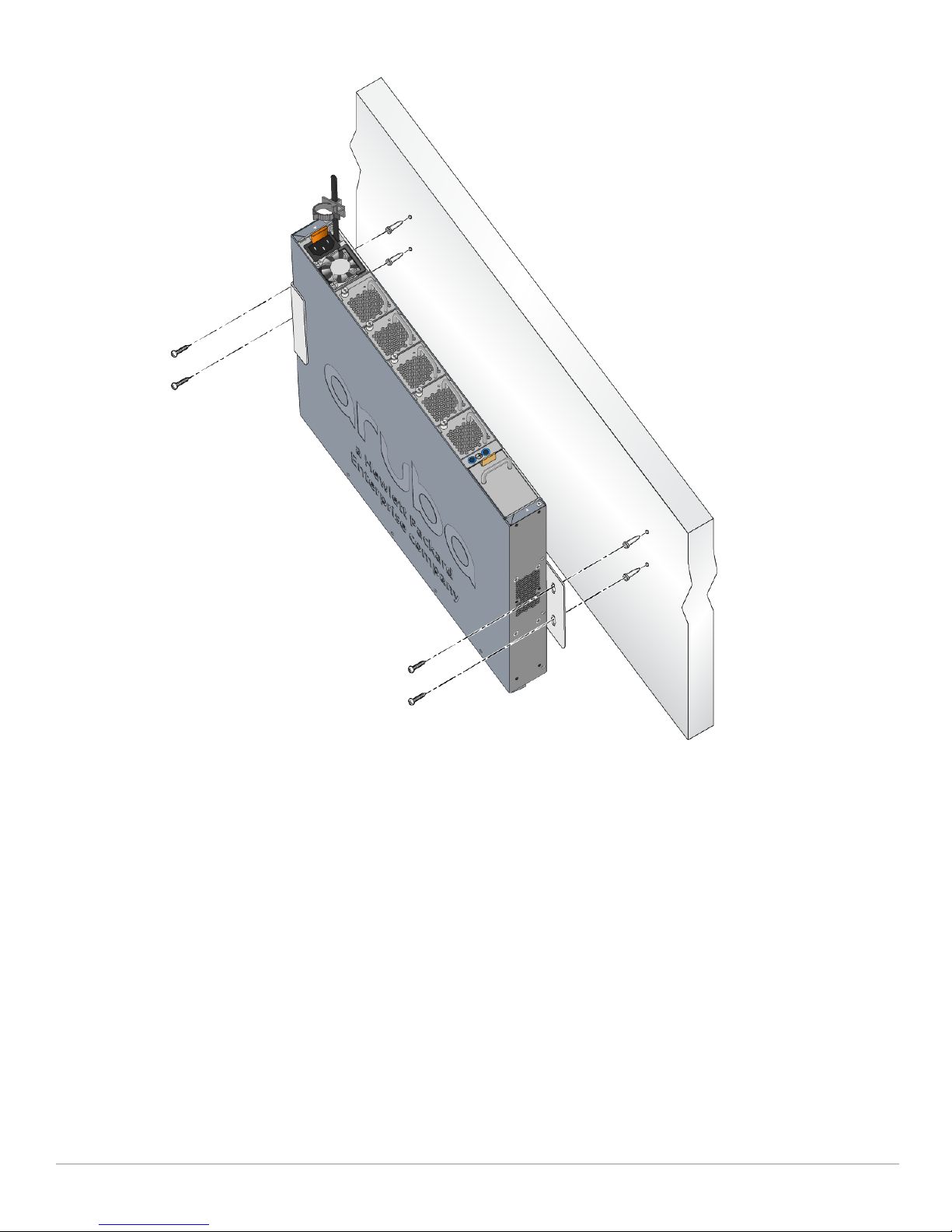
Figure 11 Wall Mounting
Connecting and Disconnecting the AC Power Cord
Once you have installed the 7280 controller, you are ready to power on the device. The 7280
controller is not equipped with an On/Off switch. The device will power on when the AC power cord is
connected to the power supply and an AC power outlet.
To connect the AC power cord to the 7280 controller:
1. Insert the coupler end of the AC power cord into the AC power connector on the power supply
module.
2. Secure the AC power cord using the cable retention holder attached on the power supply module.
See Figure 12.
Aruba 7280 Controller | Installation Guide Installation | 25
Page 26

Figure 12 Cable Retention Holder on Power Supply Module
The 7280 controller should now be receiving power.
To disconnect the AC power cord from the 7280 controller:
1. Loosen the cable retention holder that is securely holding the AC power cord.
2. Pull the AC power cord from the power supply module.
The 7280 controller is now turned Off.
If two power supply modules are installed in the controller, disconnect AC power cord from both power supply
modules to turn off the controller.
Removing and Installing a Fan Module
Use standard ESD precautions when installing or removing a fan module.
The fan module is field-replaceable and hot-swappable. Hot-swapping allows you to replace the fan
module without having to power down the controller.
To install and remove a fan module:
1. Remove the old fan module.
a. Using a Phillips Head screwdriver, turn the screws counter-clockwise until loose (they cannot
be removed completely).
b. Use the fan module handle to pull the fan module out.
2. Align the new fan module with opening in the controller.
Ensure that fan module is correctly aligned with the opening on the controller. Failure to do so can result in
damage to the fan module.
3. Insert the fan module into the controller.
4. Tighten the screw on the fan module to secure it.
26 |Installation Aruba 7280 Controller | Installation Guide
Page 27
Installing and Removing a Power Supply Module
Never insert or remove a power supply module while the power cord is connected. Verify that cord has been
disconnected from the power supply before installation or removal.
Use standard ESD precautions when installing or removing a power supply module.
The power supply module is hot-swappable when two power supplies are installed. Hot swapping
allows you to replace a failed power supply without powering down the 7280 controller during the
replacement process. This makes it unnecessary to shut down the 7280 controller during the
installation procedure.
Installing a Power Supply Module
If you are replacing a failed power supply, see “Removing a Power Supply Module” on page27 before
you proceed:
1. Align the new power supply module with the opening in the controller.
2. Insert the power supply module into the controller until the tab securely engages on to the
controller.
3. Insert the AC power cord in the AC connector on the power supply module. For more details, see
“Connecting and Disconnecting the AC Power Cord” on page25.
If you are adding an additional power supply module:
1. Remove the filler panel in PSU slot 1 by pulling the tab on filler panel towards the left and sliding it
out using the handle.
2. Align the additional power supply module with the opening in the controller.
3. Insert the power supply module into the controller until the tab securely engages on to the
controller.
4. Insert the power cord in the AC connector on the power supply module. For more details, see
“Connecting and Disconnecting the AC Power Cord” on page25.
Removing a Power Supply Module
To remove the power supply from the 7280 controller:
1. Remove the power cord in the AC connector on the power supply module. For more details, see
“Connecting and Disconnecting the AC Power Cord” on page25.
2. Lift the handle on the power supply module.
3. Pull the tab on the power supply module towards the left and slide it out using the handle.
Installing an SFP/SFP+/QSFP+/LC Cable
SFP/SFP+/QSFP+ modules are collectively referred as SFP modules in this section.
Use standard ESD precautions when installing or removing an SFP.
Aruba 7280 Controller | Installation Guide Installation | 27
Page 28
Connecting the SFP module
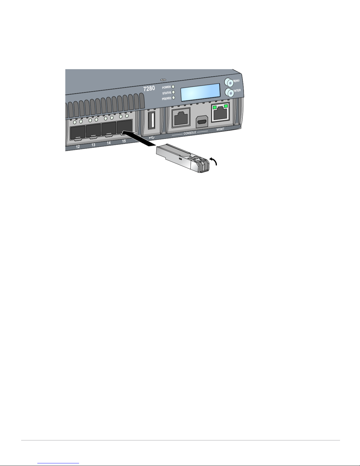
To connect an SFP module into the 7280 controller, slide the SFP module, top side facing upward, into
a corresponding 1000Base-X port or 40 GbE QSFP+ port until a connection is made and an audible
click is heard (see Figure 13).
Figure 13 Installing an SFP
Removing an SFP Module
To remove an SFP module:
1. Open and release the latch on the module.
2. Pull and remove the module from the port.
Connecting an LC Cable
To connect a LC fiber cable into an SFP module:
1. Clean the LC fiber optic cable connector before inserting it into the SFP module.
2. Insert the LC fiber optic cable into the SFP module. Ensure that the latch on the cable faces the top
of the SFP module (see Figure 14).
3. Slide the cable into place until a connection is made and an audible click is heard.
Disconnecting an LC Cable
To disconnect an LC fiber optic cable from an SFP module, depress the transceiver handle to release
the latch on the cable and simultaneously pull the cable out of the port.
28 |Installation Aruba 7280 Controller | Installation Guide
Page 29
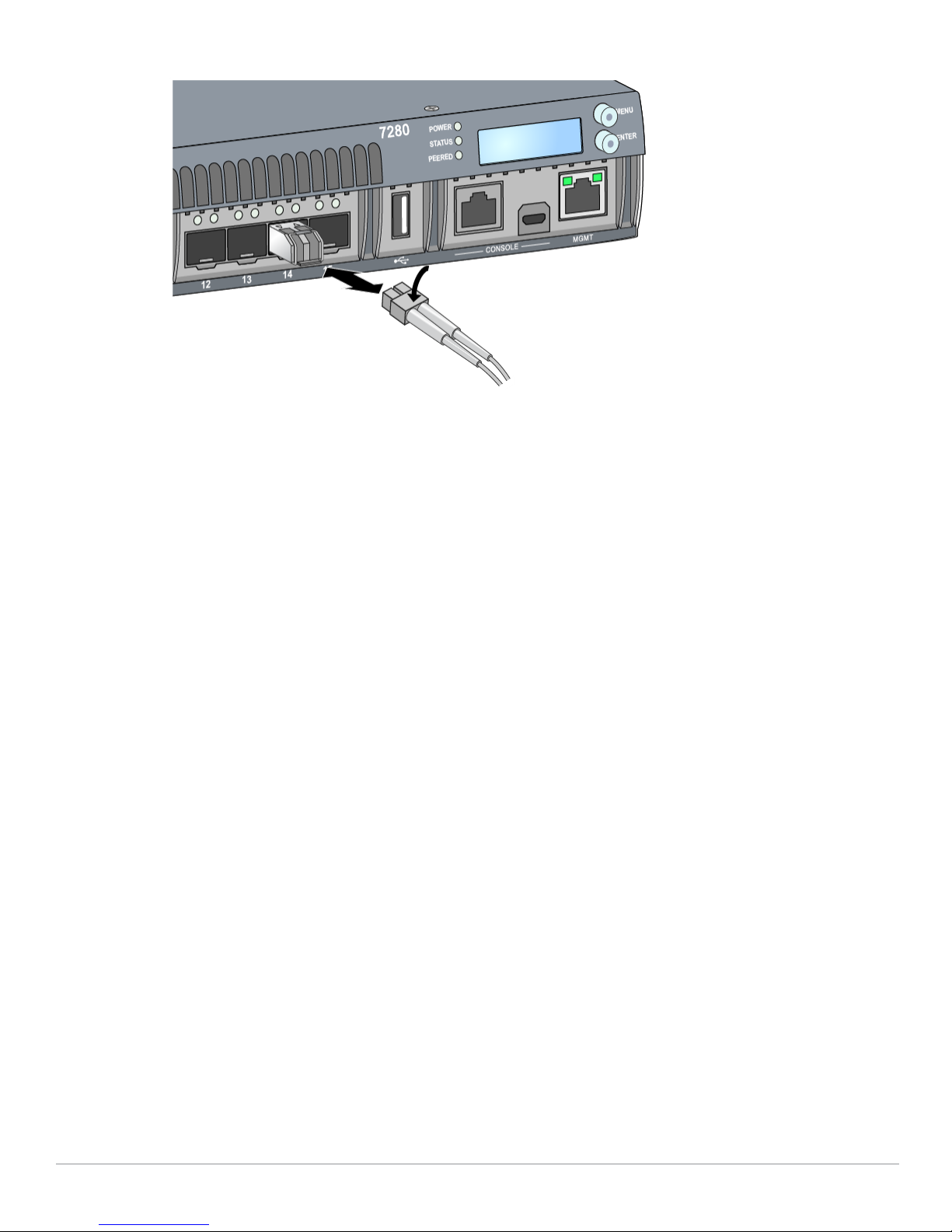
Figure 14 Connecting an LC Fiber
Aruba 7280 Controller | Installation Guide Installation | 29
Page 30

30 |Installation Aruba 7280 Controller | Installation Guide
Page 31
Chapter 3
Specifications, Safety, and
Compliance
7280 Specifications
Physical
Device Dimensions (without mounting brackets) (HxWxD): 1.73” x 17.40” x 15.79” (4.4 cm x 44.2 cm
x 40.1 cm)
Device Weight: 17.41 lbs (7.9 kg)
Power Supply Specifications
550W AC Power Supply
AC Input Voltage: 100 VAC to 240 VAC
AC Input Current: 7.1 A max
AC Input Frequency: 50 to 60 Hz
Operating Specifications
Operating Temperature Range: 0 °C to 40 °C (32 °F to 104 °F)
Operating Humidity Range: 10% to 90% (RH), non-condensing
Storage Specifications
Storage Temperature Range: –40 °C to 70 °C (-40 °F to 158 °F)
Storage Humidity Range: 10% to 95% (RH), non-condensing
Operating Altitude
Operating Altitude Range: 0 to 10,000 ft
Regulatory Model Name
The regulatory model name for the 7280 controller is ARCN7280.
Safety and Regulatory Compliance
Aruba Networks, Inc. provides a multi-language document that contains country-specific restrictions
and additional safety and regulatory information for all Aruba products. This document can be
viewed or downloaded from the following location: www.arubanetworks.com/safety_addendum
Aruba controllers must be installed by a professional installer. The professional installer is responsible for
ensuring that grounding is available and it meets applicable local and national electrical codes.
Aruba 7280 Controller | Installation Guide Specifications, Safety, and Compliance | 31
Page 32
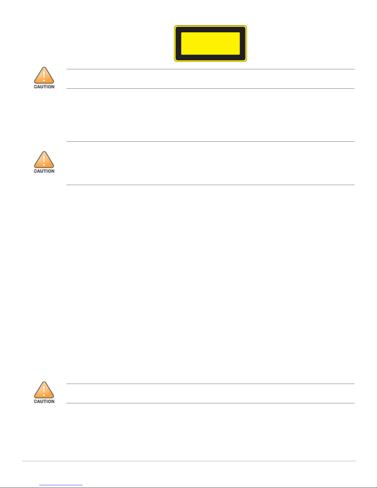
CLASS 1
LASER PRODUCT
Use of controls or adjustments of performance or procedures other than those specified in this manual may
result in hazardous radiation exposure.
This product complies with 21 CFR Chapter 1, Subchapter J, Part 1040.10, and IEC 60825-1: 1993,
A1: 1997, A2: 2001, IEC 60825-2: 2000.
For continued compliance with the above laser safety standards, only approved Class 1 modules
from our approved vendors should be installed in the product.
Although this controller has been tested up to 1kV per CE immunity requirements, this product requires surge
protection to be provided as part of the building installation to protect against unidirectional surges resulting
from electrical switching and lightning strikes.
For protection against these surges in an outdoor installation, any exposed wiring must be shielded, and the
shield for the wiring must be grounded at both ends.
Electromagnetic Interference
United States
This equipment has been tested and found to comply with the limits for a Class A digital device,
pursuant to Part 15 of the FCC Rules. These limits are designed to provide reasonable protection
against harmful interference when the equipment is operated in a commercial environment. This
equipment generates, uses, and can radiate radio frequency energy and, if not installed and used in
accordance with the instruction manual, may cause harmful interference to radio communications.
Operation of this equipment in a residential area is likely to cause harmful interference in which case
the user will be required to correct the interference at their own expense.
Any changes or modifications not expressly approved by the party responsible for compliance could
void the user’s authority to operate this equipment.
This product complies with Part 15 of the FCC Rules. Operation is subject to the following two
conditions: (1) this device may not cause harmful interference, and (2) this device must accept any
interference received, including interference that may cause undesired operation.
Canada
This Class A digital apparatus complies with Canadian ICES-003.” & “Cet appareil numérique de la
classe A est conforme à la norme NMB-003 du Canada.
Europe
This is a Class A product. In a domestic environment, this product may cause radio interference in which case
the user may be required to take adequate measures.
32 | Specifications, Safety, and Compliance Aruba 7280 Controller | Installation Guide
Page 33
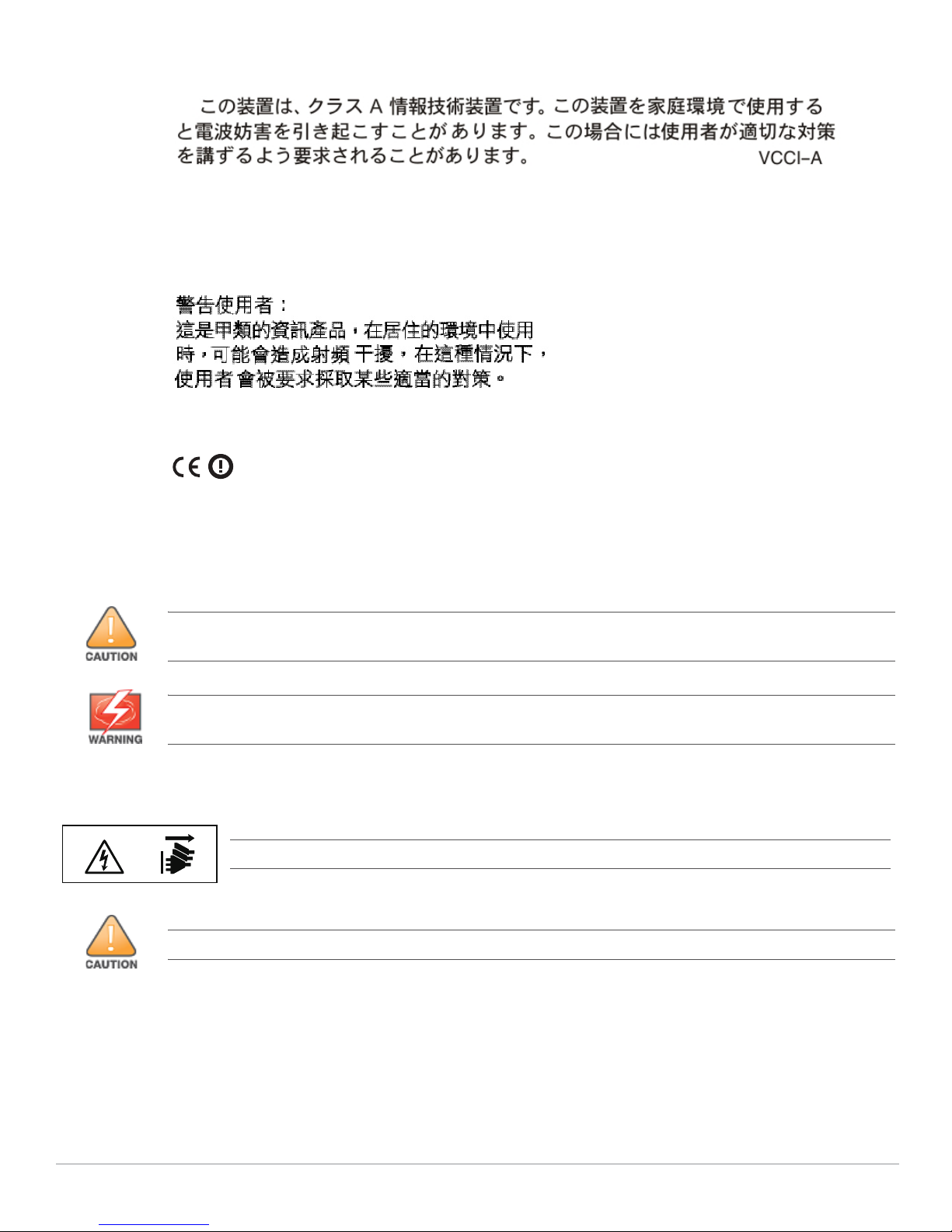
Japan VCCI
This is a Class A product. In a domestic environment this product may cause radio interference in
which case the user may be required to take corrective actions.
Taiwan (BSMI)
EU Regulatory Conformance
This product is CE marked according to the provisions of the EMC Directive (2004/108/EC)
- CE. Aruba Networks Inc., hereby declares that 7280 controller device models are in
compliance with the essential requirements and other relevant provisions of Directive
(2004/108/EC). CE The Declaration of Conformity made under Directive 1999/5/EC is available for
viewing at the following location in the EU community.
Battery Statements
The battery supplied with this product may contain perchlorate material. Special handling may apply in
California and other certain states. See www.dtsc.ca.gov/hazardouswaste/perchlorate for more information.
Risk of explosion if battery is replaced by an incorrect type. Dispose of used batteries according to the
instructions.
Other Safety Compliance
Shock hazard. Disconnect both power cords to remove power.
For indoor use only. The controller, AC power cord, and all connected cables are not designed for outdoor use.
Aruba 7280 Controller | Installation Guide Specifications, Safety, and Compliance | 33
Page 34
Proper Disposal of Aruba Equipment
Ქኂ‛ ჿ䋼
Hazardous Materials Declaration
Ქኂ‛䋼ᚗర⚛Hazardous Substances)
ㇱઙฬ⒓
(Parts)
䪙
Lead
(Pb)
ᳮ
Mercury
(Hg)
䬝
Cadmium
(Cd)
ચ䫀
Chromium VI
Compounds
(Cr6+)
ᄙ
⒈ 㘨
⧶
Polybrominated
Biphenyls
(PBB)
ᄙ⒈䝮⧶
Polybrominated
Diphenyl Ether
(PBDE)
⬉
〝᧼
PCA Board
X O O O O O
㒘ઙ
Mechanical
Subassembly
X O O O O O
⬉
Ḯㅎ㈩ེ
Power Adaptor
X O O O O O
O:␜䆹Ქኂ‛䋼䆹ㇱઙᚲဋ䋼᧚ᢱ⊛㊂ဋSJ/T11363-2006ಎ㾘ቯ⊛㒢㊂ⷐ᳞એޕ
This component does not contain this hazardous substance above the maximum concentration values in homogeneous materials
specified in the SJ/T11363-2006 Industry Standard.
X: ␜䆹Ქኂ‛䋼⥋ዋ䆹ㇱઙ⊛ᨱ৻ဋ䋼᧚ᢱ⊛㊂SJ/T11363-2006ಎ㾘ቯ⊛㒢㊂ⷐ᳞ޕ
This component does contain this hazardous substance above the maximum concentration values in homogeneous materials specified
in the SJ/T11363-2006 Industry Standard.
ᇍ䫔ଂП᮹ⱘ᠔ଂѻકᴀ㸼ᰒ⼎կᑨ䫒ⱘ⬉ᄤֵᙃѻકৃ㛑ࣙ䖭ѯ⠽䋼ޕ
This table shows where these substances may be found in the supply chain of electronic information products, as of the date of sale of
the enclosed product.
ℸᖫЎ䩜ᇍ᠔⍝ঞѻકⱘ⦃ֱՓ⫼ᳳᖫ
ᶤѯ䳊䚼ӊӮ᳝ϔϾϡৠⱘ⦃ֱՓ⫼ᳳ՟བ⬉∴ܗഫ䌈݊ѻકϞ
ℸ⦃ֱՓ⫼ᳳ䰤া䗖⫼ѢѻકᰃѻકݠЁ᠔㾘ᅮⱘᴵӊϟᎹ
The Environment- Friendly Use Period (EFUP) for all enclosed products and their parts are per the
symbol shown here. The Environment- Friendly Use Period is valid only when the product is operated
under the conditions defined in the product manual.
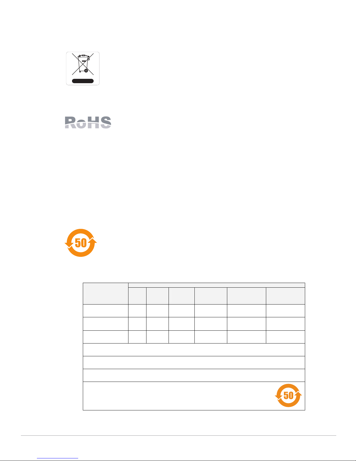
Waste of Electrical and Electronic Equipment
Aruba products at end of life are subject to separate collection and treatment in the
EU Member States, Norway, and Switzerland and therefore are marked with the
symbol shown at the left (crossed-out wheelie bin). The treatment applied at end of
life of these products in these countries shall comply with the applicable national
laws of countries implementing Directive 2002/96EC on Waste of Electrical and
Electronic Equipment (WEEE).
European Union RoHS
Aruba products also comply with the EU Restriction of Hazardous Substances
Directive 2002/95/EC (RoHS). EU RoHS restricts the use of specific hazardous
materials in the manufacture of electrical and electronic equipment. Specifically,
restricted materials under the RoHS Directive are Lead (including Solder used in printed circuit
assemblies), Cadmium, Mercury, Hexavalent Chromium, and Bromine. Some Aruba products are
subject to the exemptions listed in RoHS Directive Annex 7 (Lead in solder used in printed circuit
assemblies). Products and packaging will be marked with the “RoHS” label shown at the left indicating
conformance to this Directive.
India RoHS
This product complies with RoHS requirements as prescribed by E-Waste (Management & Handling)
Rules, governed by the Ministry of Environment & Forests, Government of India.
China RoHS
Aruba products also comply with China environmental declaration requirements and
are labeled with the “EFUP 50” label shown at the left.
34 | Specifications, Safety, and Compliance Aruba 7280 Controller | Installation Guide
 Loading...