

Page 1

USER MANUAL
_AUDIOFUSE X8 IN
Page 2
Special Thanks
DIRECTION
Frédéric Brun Kévin Molcard Jean-Gabriel Schoenhenz
PROJECT MANAGEMENT
Loïc Baum Thierry Chatelain
HARDWARE DEVELOPMENT
Laurent Baret
Valentin Depoisier
INDUSTRIALIZATION
Jérôme Blanc Yi-chun Hung
QUALITY
Emilie Jacuszin
DESIGN
Martin Dutasta Axel Hartmann Farès Mezdour
QUALITY ASSURANCE
Nicolas Naudin Félix Roux
Lionel Ferragut
Nadine Lantheaume
Matthieu Ode
PRODUCTION TESTS
Anton Faugier Yoann Lubiato
MANUAL
Mike Metlay
Jimmy Michon
Charlotte Métais (French)
Holger Steinbrink (German)
BETA TESTING
Laurent Ballot
Jérôme Blanc
Sebastien Camhi
© ARTURIA SA – 2024 – All rights reserved.
26 avenue Jean Kuntzmann
38330 Montbonnot-Saint-Martin
FRANCE
arturia.com
Perceval Carré
Daniel Cayotte
Olivier Collier
Minoru Koike (Japanese)
Ana Artalejo (Spanish)
Sébastien Gros
Olivier Hudry
Godfrey Kirke
Yoan Lubiato
Aurélien Mortha
Vincent Travaglini
Page 3

Information contained in this manual is subject to change without notice and does not
represent a commitment on the part of Arturia. The software described in this manual is
provided under the terms of a license agreement or non-disclosure agreement. The software
license agreement specifies the terms and conditions for its lawful use. No part of this
manual may be reproduced or transmitted in any form or by any purpose other than
purchaser’s personal use, without the express written permission of ARTURIA S.A.
All other products, logos, or company names quoted in this manual are trademarks or
registered trademarks of their respective owners.
Product version: 1.0.0
Revision date: 10 September 2024
Page 4

Thank you for purchasing AudioFuse X8 IN!
AudioFuse X8 IN allows for easy expansion of your studio's input count, while retaining the
same superior sound quality found in the entire Arturia Fuse lineup.
This manual covers the features and operation of the AudioFuse X8 IN.
Important Safety Instructions
PRECAUTIONS INCLUDE, BUT ARE NOT LIMITED TO, THE FOLLOWING:
1. Read and understand all the instructions.
2. Always follow the instructions on the device.
3. Before cleaning the device, always remove the USB and DC cable. When
cleaning, use a soft and dry cloth. Do not use gasoline, alcohol, acetone,
turpentine or any other organic solutions; do not use a liquid cleaner, spray or
cloth that's too wet.
4. Do not use the device near water or moisture, such as a bathtub, sink, swimming
pool or similar place.
5. Do not place the device in an unstable position where it might accidentally fall
over.
6. Do not place heavy objects on the device. Do not block openings or vents of the
device; these locations are used for air circulation to prevent the device from
overheating. Do not place the device near a heat vent at any location with poor
air circulation.
7. When rackmounting the device, allow air circulation space above and below it
for heat dissipation, and use caution when installing in the rack to avoid damage
to the rack ears and mounting screws.
8. Do not open or insert anything into the device that may cause a fire or electrical
shock.
9. Do not spill any kind of liquid onto the device.
10. Always take the device to a qualified service center. You will invalidate your
warranty if you open and remove the cover, and improper assembly may cause
electrical shock or other malfunctions.
11. Do not use the device with thunder and lightning present; it may cause electrical
shock.
12. Do not expose the device to hot sunlight.
13. Do not use the device when there is a gas leak nearby.
14. Arturia is not responsible for any damage or data loss caused by improper
operation of the device.
Specifications subject to change:
The information contained in this manual is believed to be correct at the time of printing.
However, Arturia reserves the right to change or modify any of the specifications without
notice or obligation to update the hardware that has been purchased.
Page 5

IMPORTANT:
The product and its software, when used in combination with an amplifier, headphones or
speakers, may be able to produce sound levels that could cause permanent hearing loss.
DO NOT operate for long periods of time at a high level or at a level that is uncomfortable. If
you encounter any hearing loss or ringing in the ears, you should consult an audiologist.
NOTICE:
Service charges incurred due to a lack of knowledge relating to how a function or feature
works (when the product is operating as designed) are not covered by the manufacturer’s
warranty, and are therefore the owner's responsibility. Please study this manual carefully
and consult your dealer before requesting service.
Page 6

Introduction
Dear musician,
We’d like to thank you for purchasing the AudioFuse X8 IN, a simple and affordable input
expansion solution for your studio. Because the AudioFuse X8 IN can be configured for
tabletop or rackmount operation, it will serve you well whether you're just getting started
or expanding your existing setup with the very best equipment. This manual will help you
make the most of the AudioFuse X8 IN.
As with the other interfaces in our Fuse lineup, the AudioFuse X8 IN has been constructed
using components of the utmost quality so as to achieve recordings of the utmost quality.
It offers high-quality analog-to-digital (A/D) conversion and up to 24-bit/96 kHz audio
transmission, with internal or external clock sync.
Be sure to visit arturia.com website for information about all of our other great hardware
and software instruments. They have proven time and again to be the go-to solutions for
musicians around the world.
Wishing you all the best in your musical endeavors,
The Arturia team
Page 7

Table Of Contents
1. Welcome to the AudioFuse X8 IN!..................................................................................................................... 2
1.1. Features of AudioFuse X8 IN: ......................................................................................................................................... 3
1.2. Diving in (suggestions on using this manual) .................................................................................................... 3
2. Hardware Setup and Registration ................................................................................................................... 4
2.1. What’s in the box? ............................................................................................................................................................... 4
2.2. Rackmounting the AudioFuse X8 IN........................................................................................................................ 4
2.3. Registration .............................................................................................................................................................................. 5
3. Getting to Know the AudioFuse X8 IN........................................................................................................... 6
3.1. The Front Panel....................................................................................................................................................................... 6
3.1.1. Channel LEDs ................................................................................................................................................................................................................... 6
3.1.2. Channel selection and function buttons ....................................................................................................................................................... 6
3.1.3. Clock/Sync function buttons................................................................................................................................................................................. 6
3.1.4. Power button................................................................................................................................................................................................................... 6
3.2. The Rear Panel....................................................................................................................................................................... 7
3.2.1. Power Input..................................................................................................................................................................................................................... 7
3.2.2. ADAT Outputs................................................................................................................................................................................................................. 7
3.2.3. Word Clock Input........................................................................................................................................................................................................ 7
3.2.4. Inputs.................................................................................................................................................................................................................................. 7
4. Using the AudioFuse X8 IN .................................................................................................................................... 8
4.1. Device connections .............................................................................................................................................................. 8
4.2. Input configuration ............................................................................................................................................................. 9
4.2.1. Channel metering ........................................................................................................................................................................................................ 9
4.2.2. Edit Mode .......................................................................................................................................................................................................................... 9
5. Synchronization ........................................................................................................................................................... 11
5.1. Why synchronize? .............................................................................................................................................................. 11
5.2. Internal Sync.......................................................................................................................................................................... 11
5.3. Word Clock Sync................................................................................................................................................................ 12
5.3.1. Switching between ADAT and Word Clock ............................................................................................................................................... 12
5.3.2. Use case : Sync two AudioFuse X8 IN units with an AudioFuse 16 Rig ................................................................................ 12
5.4. Sample rates and CLOCK............................................................................................................................................. 14
5.5. A final note.............................................................................................................................................................................. 14
6. Specifications ............................................................................................................................................................... 15
7. Declaration of Conformity.................................................................................................................................... 16
7.1. FCC ................................................................................................................................................................................................ 16
7.2. CANADA..................................................................................................................................................................................... 16
7.3. CE .................................................................................................................................................................................................. 16
7.4. ROHS ........................................................................................................................................................................................... 16
7.5. WEEE............................................................................................................................................................................................ 17
Page 8
1. WELCOME TO THE AUDIOFUSE X8 IN!
The AudioFuse X8 IN
When Arturia released the AudioFuse USB audio interface in 2017, its features and design
were a revelation to the pro audio world. Every part of its analog and digital signal paths
provided world-class quality, from high-performance preamps to premium A/D and D/A
converters. Even with all these features, it fit into a compact, beautifully-engineered design
that set a new price/performance standard.
Since then, Arturia has expanded its Fuse lineup with other rackmount and desktop
interfaces – from specialized AudioFuse products to smaller MiniFuse interfaces perfect for
smaller studios. All of these products continue our commitment to maximum features for
the money, all with uncompromising sound quality.
The AudioFuse line is designed to grow with you as your interface needs change. Our
newest Fuse units, the AudioFuse X8 IN and X8 OUT, have been created to help with
one of the most common growing pains that electronic musicians face: running out of
analog inputs and outputs. What do you do if you love your current interface (and if it's an
AudioFuse, who
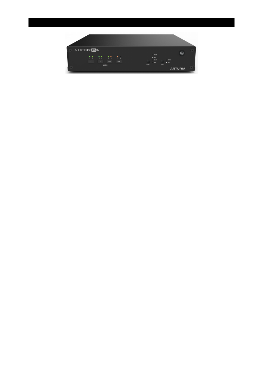
The AudioFuse X8 IN is a half-rackspace unit with 8 balanced line-level inputs on 1/4" TRS,
each with a world-class analog-to-digital (A/D) converter. Output is provided on a pair of
Toslink optical ports using the ADAT digital audio standard, which run at 24-bit resolution
and can operate at sample rates up to 96 kHz. These will provide data to any audio interface
with ADAT inputs. Each input can have a switchable 12 dB Pad for loud input signals, and
pairs of adjacent odd and even inputs can be Linked for easy stereo operation.
In addition to these features, the AudioFuse X8 IN can send clock signals over the ADAT
outputs or receive Word Clock signals via a rear-panel BNC input with switchable
termination. This lets you synchronize your audio interface to the AudioFuse X8 IN directly,
or integrate it with a larger digital audio system using a common Word Clock.
The AudioFuse X8 IN comes in a convenient half-rackspace chassis, complete with one rack
ear and one connector plate. These stay out of the way when using the AudioFuse X8 IN as a
tabletop unit, and can be removed and put into use when attaching it to a second AudioFuse
X8 IN or an AudioFuse X8 OUT 8-channel ADAT-to-line digital-to-analog (D/A) converter unit.
The result is a conventional single-rackspace processor that can be added to any standard
rackmount system.
Simple to set up and seamless to use, the AudioFuse X8 IN is the easiest way to add more
inputs to your audio interface rig – so you can always add that new synthesizer you've had
your eye on! (And then another, and another...!)
wouldn't
?) but you wish it had more ins or outs?
*,-*$+ *'-%-$(-+ %(& ,(,# -$(-+
Page 9

1.1. Features of AudioFuse X8 IN:
• 8 balanced line-level analog input channels on TRS
• Pad switch for each input channel
• Stereo Link switching for odd/even pairs of adjacent channels (1/2, 3/4, 5/6, 7/8)
• Dual ADAT output ports for 8 channels of input at 44.1, 48, 88.2, or 96 kHz
• BNC Word Clock input with impedance switching
• Robust metal chassis in a half-rackspace form factor
• built-in feet for tabletop use plus attached hardware for rackmount configuration
• Operates standalone with no computer needed
1.2. Diving in (suggestions on using this manual)
In this manual, you'll be introduced to all of the AudioFuse X8 IN's functions, step by step.
The Table of Contents is laid out by section, with some general information at the beginning
and end. Inside each section, you can click on topic and page references to quickly find
what you need.
This isn't a complex machine, but knowing its features ahead of time will help you set it up
quickly and use it without headaches. Take some time to read through this manual so you
know how to get what you need.
And above all: have fun! That's what music is all about.
*,-*$+ *'-%-$(-+ %(& ,(,# -$(-+
Page 10
2. HARDWARE SETUP AND REGISTRATION
Setting up the AudioFuse X8 IN isn't difficult, but there are a few instructions to follow,
especially if you plan to rackmount it with another X8 IN or with an X8 OUT.
2.1. What’s in the box?
• The AudioFuse X8 IN
• Rack ear and connecting plate with screws (attached to the bottom of the unit)
• Power supply with adapters for worldwide use
• Registration card with serial number
• Quick Start Guide
2.2. Rackmounting the AudioFuse X8 IN
Rackmounting
components stored under
the AudioFuse X8 IN
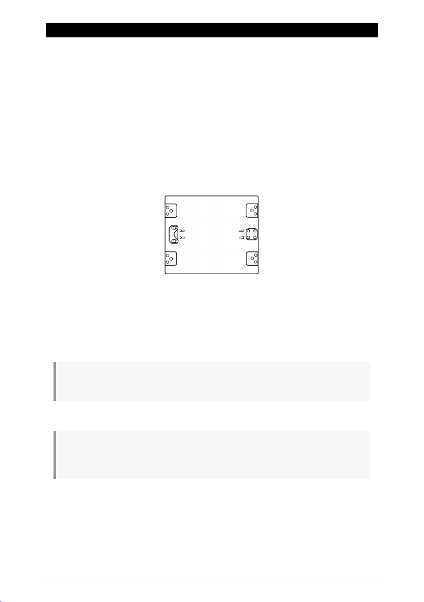
The bottom of the unit has a pair of recessed storage positions, one for a single orange
rack ear and one for a square connecting plate. Each has two mounting screws of the
appropriate size.
Note that the connecting plate has four screw holes but only two screws. The extra holes are used
to connect to a second unit using its supplied screws.
The unit comes with mounting screws especially chosen for this purpose. Don't use other screws,
and carefully follow the directions in this manual. You don't want your new converter to fall out of your
rack, do you?
*,-*$+ *'-%-$(-+ *.* ,-)' "$+,*,$('
Page 11
AudioFuse X8 IN configured for rackmounting
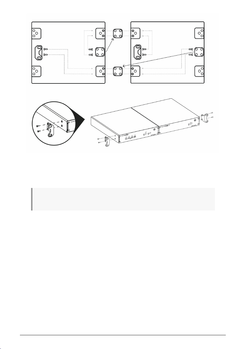
Attach the rack ears and connection plates in the configuration shown above, and the
AudioFuse X8 IN and its companion X8 IN or X8 OUT are ready to slot into your rack.
We recommend rackmounting the AudioFuse X8 units with an open rackspace above or below them,
to assist with keeping them cool during operation.
2.3. Registration
Once you've set u p your hardware, the next part of the process is to register it with Arturia.
Registration will help you if you should need technical support; it's always a good idea to
take a moment and do this before you get started.
Follow the instructions you'll find in the box with your unit to log onto the Arturia website and
register it. You will need a serial number and unlock code, which you will find on the bottom
of the unit.
Registering your AudioFuse X8 IN gives you access to current documentation (including this
User Manual).
*,-*$+ *'-%-$(-+ *.* ,-)' "$+,*,$('
Page 12
3. GETTING TO KNOW THE AUDIOFUSE X8 IN
Before we get started using it, let's take a tour around the AudioFuse X8 IN.
3.1. The Front Panel
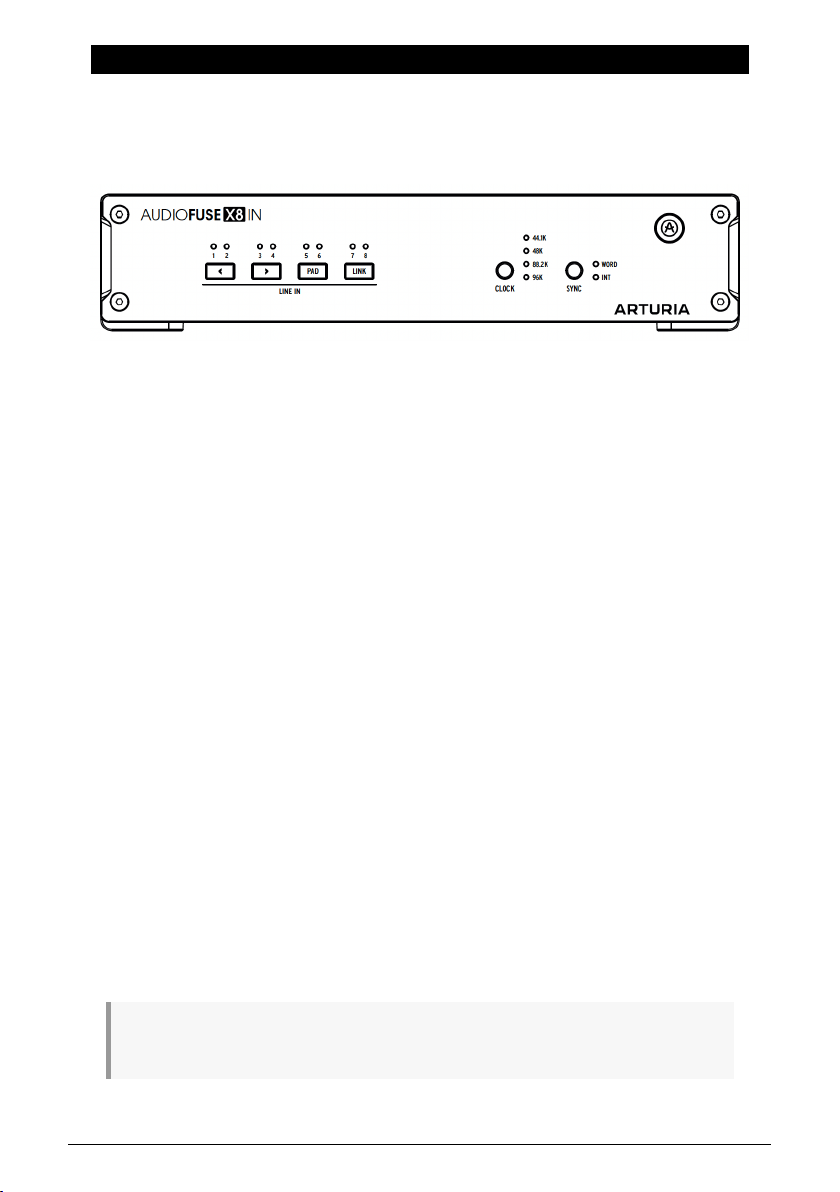
The AudioFuse X8 IN front panel
The front panel has the following features:
3.1.1. Channel LEDs
The eight LINE IN channels have LEDs that act as either level meters or as indicators in Edit
Mode [p.9].
3.1.2. Channel selection and function buttons
Under each pair of channel LEDs is one button for a total of four:
• LEFT Arrow: moves control to the previous channel
• RIGHT Arrow: moves control to the next channel
• PAD: turns the Pad function on and off for the selected channel
• LINK: turns the stereo Link function on and off for a pair of adjacent channels
3.1.3. Clock/Sync function buttons
• CLOCK: selects the clock rate (44.1, 48, 88.2, or 96 kHz)
• SYNC: selects whether the AudioFuse X8 will accept BNC Word Clock on the rear
panel (WORD) or send its internal clock to your interface over the ADAT Outputs
(INT)
3.1.4. Power button
The round button with the Arturia logo at the far right powers the unit on or off when held
for two seconds. It glows white when the unit is on.
When you power the unit on, all of the front panel LEDs will cycle from left to right. This is the unit's
bootup sequence, and should only take one or two seconds.
*,-*$+ *'-%-$(-+ ,,$'",('(.,# -$(-+
Page 13
3.2. The Rear Panel
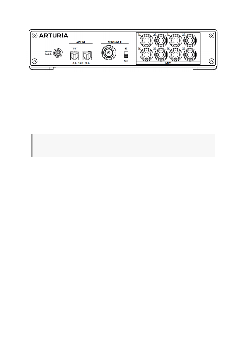
The AudioFuse X8 IN rear panel
The AudioFuse X8 IN's rear panel has the following sets of connections.
3.2.1. Power Input
The AudioFuse X8 IN has a locking power connector for the provided 15V / 2A DC power
supply.
Use only the provided supply! Other supplies might damage or destroy the unit, and will void your
warranty.
3.2.2. ADAT Outputs
The two Toslink ADAT optical outputs are used to provide 8 channels of digital audio to your
interface.
• When running at 44.1 or 48 kHz, the left port carries data for all 8 channels.
• When running at 88.2 or 96 kHz, each port carries data for four channels, 1–4 and
5–8.
3.2.3. Word Clock Input
This is a standard BNC connector for Word Clock data provided by an external clock source.
The HiZ switch determines the termination of the connection.
3.2.4. Inputs
These eight 1/4" TRS jacks carry balanced line-level signals into the AudioFuse X8 IN. They
can be used in mono, or configured as up to four stereo pairs per the front-panel LINK
button.
*,-*$+ *'-%-$(-+ ,,$'",('(.,# -$(-+
Page 14
4. USING THE AUDIOFUSE X8 IN
Hooking up your AudioFuse X8 IN and configuring its inputs is a simple process.
4.1. Device connections
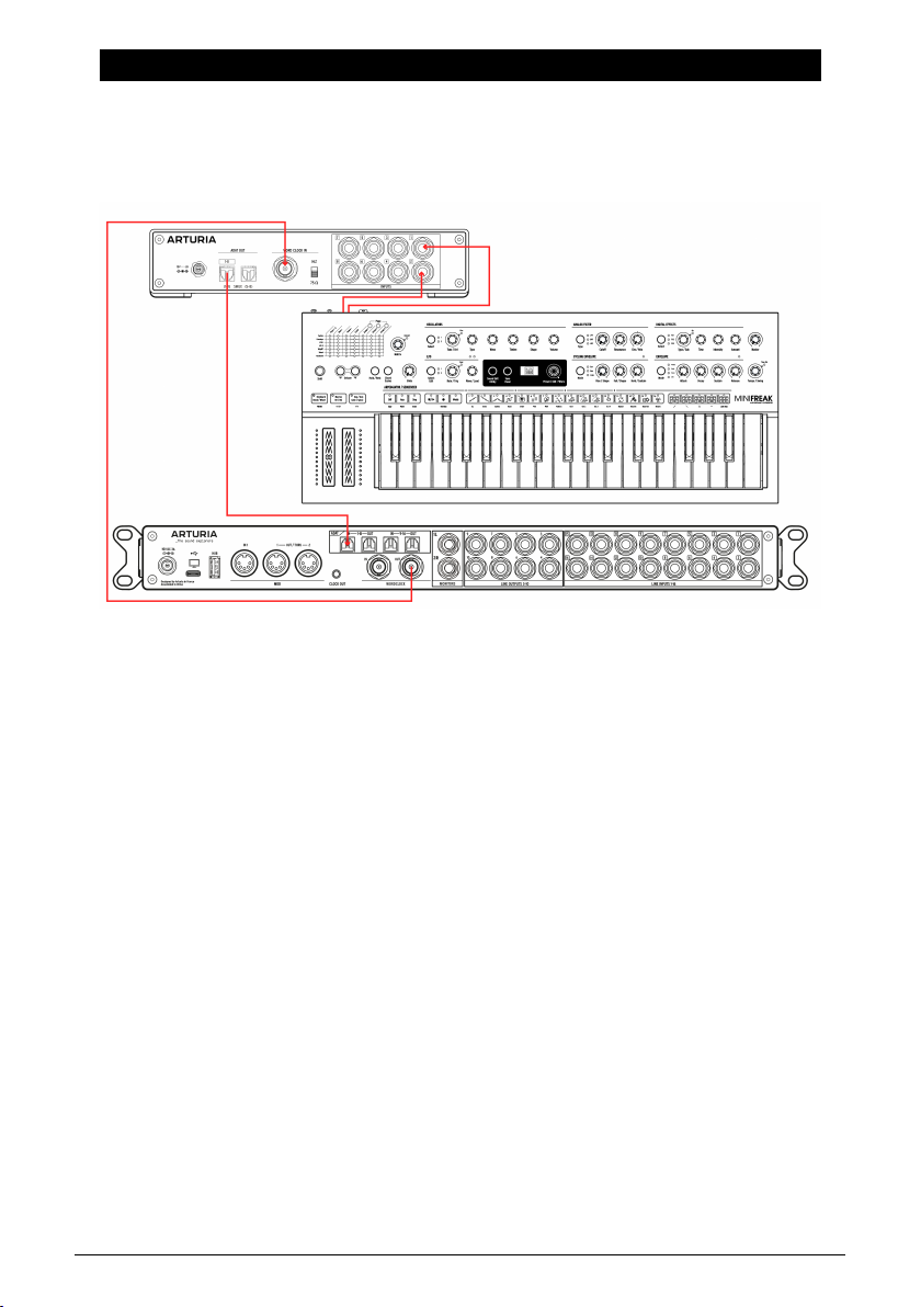
Hooking up the AudioFuse X8 IN to your system
1. Connect your analog devices to the rear-panel inputs. If any device has stereo
outputs, be sure to connect them to adjacent odd/even pairs of in puts (1/2, 3/4,
5/6, 7/8). Any other configuration won't work properly with the front-panel Link
buttons.
2. Connect your ADAT optical cables from the ADAT outputs on the AudioFuse X8 IN
to the ADAT inputs on your audio interface.
3. If you're using external Word Clock, attach the BNC cable from your master
clock source. Set the HiZ switch accordingly, as explained in the chapter on
synchronization [p.11].
4. Make sure your interface recognizes the presence of the ADAT in puts and be
sure that its clock/sync settings match how the AudioFuse X8 IN is sending or
receiving clocks. Consult the chapter on sync [p.11] for more details.
5. Consult your device's user manual if things don't seem to be connecting properly.
You're now ready to configure your inputs.
*,-*$+ *'-%-$(-+ +$'",# -$(-+
Page 15
4.2. Input configuration
4.2.1. Channel metering
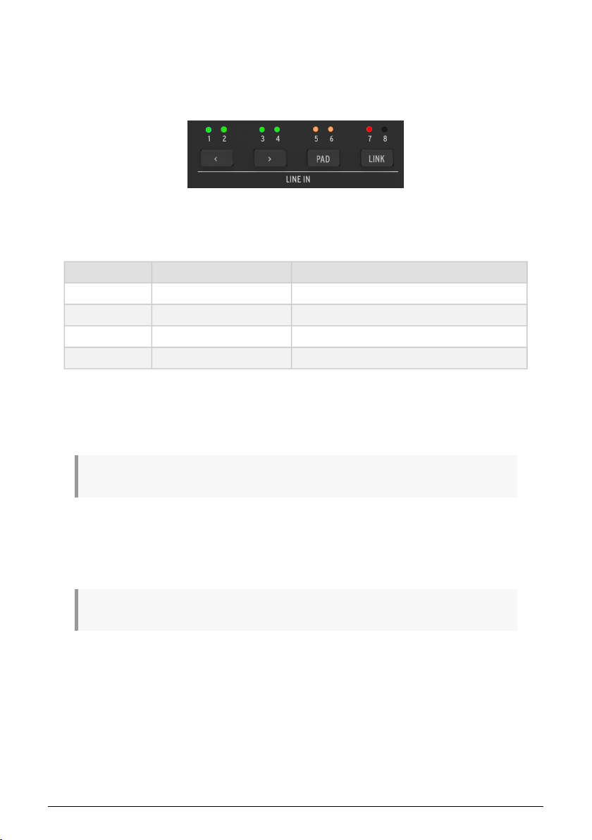
Each Line In has an LED that operates as a basic signal level meter.
LED meter colors
These LEDs have four color states:
Color Status Value
Off
Green
Orange
Red
The LEDs act as meters whenever the unit is not in Edit Mode.
Ideally, you should set the in put level of your line signals so that the LEDs turn orange on
the highest peaks and never turn red. This assures that your interface is receiving a signal
that's loud but not clipping.
Signal absent below –60 dB
Signal present between –60 dB and –6 dB
Signal hot from –6 dB up to 0 dB
Signal clipped 0 dB and above
Red clip LEDs will reset after 1.5 seconds. They will register clipping even while you're in Edit Mode.
4.2.2. Edit Mode
Pressing any of the four LINE IN function buttons enters Edit Mode. While Edit Mode is active,
you can use the buttons to control the Pad and Link status of each channel.
If you don't touch any button for 3 seconds or longer, the LEDs will revert to their level meter function.
Use the LEFT Arrow and RIGHT Arrow buttons to select inputs. Press to move by one
channel; long-press to cycle through them. The selected input's LED will flash white.
*,-*$+ *'-%-$(-+ +$'",# -$(-+
Page 16
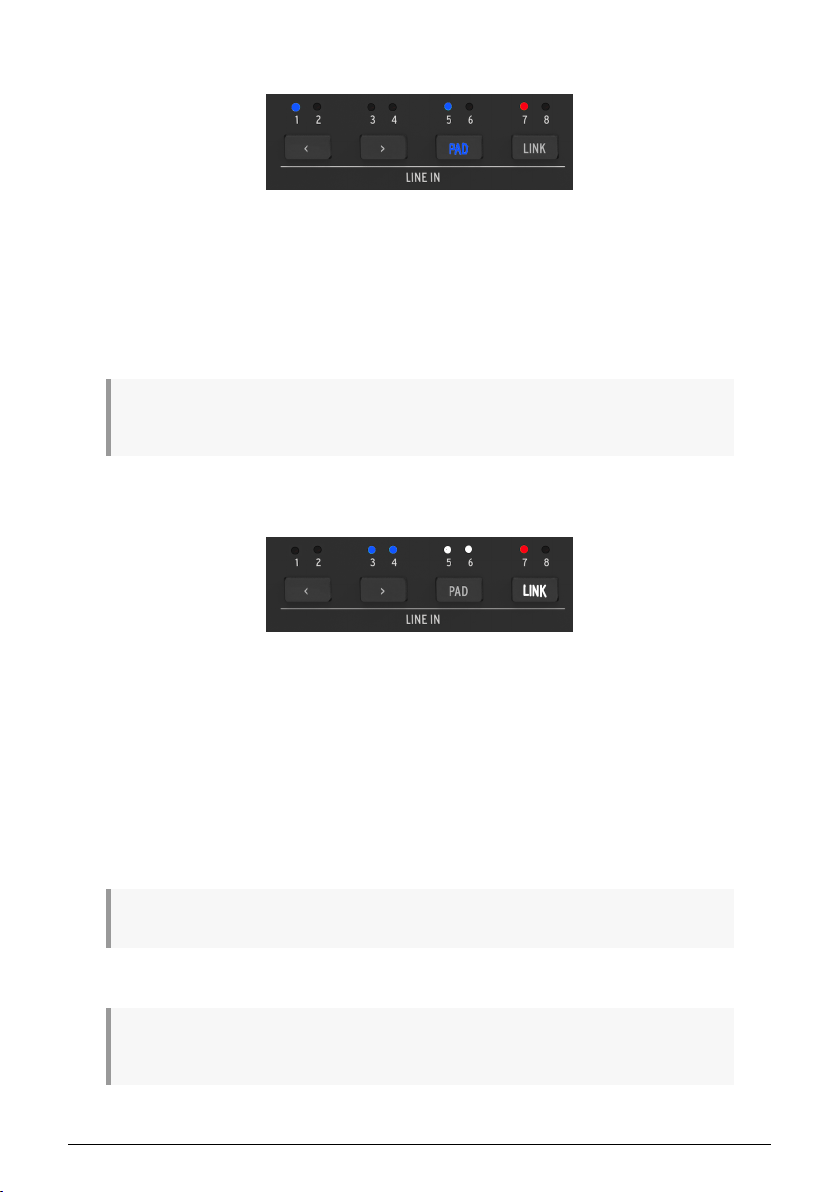
4.2.2.1. PAD
Edit Mode: PAD is set for Line In 1 and 5.
Note Line In 7 still shows clipped status.
Press the PAD button to activate the 12 dB Pad for a given input. The PAD button will light
bright blue and the selected input's LED will flash blue and white.
When you move to another input, the PAD button will return to dim white lighting, but the
previous input's LED will remain blue to show its Pad status.
While in Edit Mode, you can long-press the PAD button to toggle the Pad on and off for all 8 in puts
at once.
4.2.2.2. LINK
Edit Mode: Line IN 3/4 are already linked,
Line in 5/6 are selected and linked. Line In
Press the LINK button to pair adjacent channels (1/2, 3/4, 5/6, 7/8). The LINK button will light
bright white and the two inputs' LEDs will flash blue and white. Press again to unlink the
channels.
• You can select either input of a given pair, odd or even, to use the Link function.
• When you select or apply the Pad to Linked inputs, both LEDs will flash and
indicate Pad status together.
You can't Pad only one channel of a Linked pair.
While in Edit Mode, you can long-press the LINK button to toggle Link on and off for all 8 inputs at
once.
*,-*$+ *'-%-$(-+ +$'",# -$(-+
7 shows clipped status.
Page 17

5. SYNCHRONIZATION
The CLOCK and SYNC buttons are used to determine how the AudioFuse X8 IN is
synchronized with other digital audio devices in your studio.
5.1. Why synchronize?
If you've never used two or more devices with digital in puts or outputs before, you might
not understand why sync is such an important issue. Actually, good sync is of critical
importance to good sound.
Every digital audio device has an internal clock that determines where certain audio events
occur in time. The clock runs much faster than the sample rate of the audio you're recording
or playing back, and its precision is vital to the quality of the audio signal. If a clock isn't very
precise, an audible artifact called
clock network strives to have the lowest jitter.
When multiple clocked devices are connected, only one can be the master clock generator,
and the other devices must tightly follow its clock signals. It is vital to make sure that
all digital audio devices in a studio are clocked from the same source, so you don't
introduce clicks, pops, and other audio artifacts that can arise from slightly mismatched
and competing clocks. Generally you'll choose whichever device has the most stable clock
signals to control the others.
When connecting only two devices (e.g. the AudioFuse X8 IN and your interface), the clock
signals can be sent over the ADAT cable connecting them. If more than two devices are in a
network, they must share a Word Clock signal that is transmitted between them on a BNC
cable with a locking connector. One Master unit provides the clock signals for all other units.
In very high-end studios with a lot of digital devices, there will be a standalone Master Clock
box to give the best possible clocking throughout the studio.
BNC cables can be chained from unit to unit in various ways, but they are very sensitive to
pulses that reflect back down the cable from its far end. To prevent this, clock cables must
be
terminated
with a proper resistance value.
jitter
will become part of the signal. Every digital audio
5.2. Internal Sync
Digital audio signals always have some kind of sync data included with them. It's part of
the ADAT optical data stream. When using it, the SYNC button must be set to INT (indicated
with a white LED).
If no BNC cable is connected to the rear panel WCLOCK input, the SYNC button doesn't do anything
– the unit defaults to Internal sync and can't be changed.
*,-*$+ *'-%-$(-+ /'#*('$0,$('
Page 18
5.3. Word Clock Sync
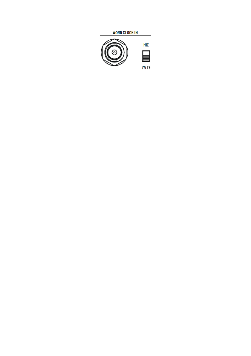
The rear panel BNC WCLOCK port is used to connect the AudioFuse X8 IN to multiple devices
in a digital audio network. The HiZ switch determines how the connection is "seen" by other
devices that are cabled together.
• When the HiZ switch is in the down position, the connection's input impedance is
75 Ohms. This is used when the AudioFuse X8 IN is at the end of a chain of word
clock cables.
• When the HiZ switch is in the u p position, the connection has a very high
impedance, which prevents reflections in all other hookup configurations.
5.3.1. Switching between ADAT and Word Clock
If the AudioFuse X8 IN has a BNC connection, you can switch between it and the ADAT clock
with the SYNC button.
5.3.2. Use case : Sync two AudioFuse X8 IN units with an
AudioFuse 16 Rig
Word clock is a clock signal used to synchronize devices together and can be used as an
alternative to ADAT Sync depending on the devices, setup and needs.
In fact, Word Clock can be used to synchronize as many digital devices in your studio as
devices can be easily chained together.
AudioFuse X8 IN provides a standard BNC connector for Word Clock data coming from an
external clock source.
• In the example below, two AudioFuse X8 IN units have been connected from their
ADAT 1 OUT ports (In 44.1 or 48Khz) to an AudioFuse 16Rig ADAT INs 1 & 2 with the
help of ADAT (Toslink optical) cables to retrieve all their 8 channels.
• A BNC cable has to be connected from the AudioFuse 16Rig Word Clock Output
to the First AudioFuse X8 IN Word Clock Input and from there connected to the
second Word Clock Input with the help of a “T” BNC connector to chain them
together (Doing so will require a “T” along with two BNC cables).
As you can see on the first unit, Word Clock termination switch will have to be set to “HiZ”
and on the second unit, will have to be set to “75 Ohm”.
*,-*$+ *'-%-$(-+ /'#*('$0,$('
Page 19
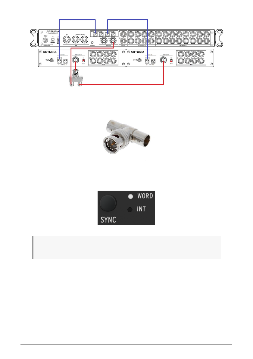
Here’s an example of “T” connector used for such kind of purpose:
Of course, in such kind of setu p, the main interface (here AudioFuse 16Rig) will have to be
set to Internal clock source and the other interfaces (here AudioFuse X8 INs) set to External
Word clock source with the help of the SYNC button located on the front panel:
If no BNC cable is connected to the rear panel WORD CLOCK input, the SYNC button doesn't do
anything – the unit defaults to Internal sync and can't be changed.
*,-*$+ *'-%-$(-+ /'#*('$0,$('
Page 20

5.4. Sample rates and CLOCK
The CLOCK button selects between four possible sample rates for the audio stream. Press
the button repeatedly to cycle through the options.
• At 44.1 or 48 kHz, all 8 channels can be transmitted down a single ADAT cable.
• At 88.2 or 96 kHz, channels 1–4 are sent down one ADAT cable and channels 5–8
are sent down the other. This operating mode is called S/MUX.
• The sample rate is determined by external Word Clock, and the LED for the old
sample rate will flash if that sample rate changes. Press the CLOCK button to
accept the new sample rate.
• If for some reason the Word Clock signal is lost, the AudioFuse X8 IN will
instantly switch to Internal clock. The Word clock LED will flash. Press the SYNC
button to accept the change in clock source.
• If the Word Clock signal is restored after being lost – for example if the Word
Clock cable is disconnected and then reconnected – Word Clock sync will
automatically be re-established.
5.5. A final note
If all this seems a bit overwhelming, just remember that using multiple Word Clock devices
is a scenario you won't run into very often... at least until your studio has grown to the
point where you'll have experience with these issues. For most small studios, a simple ADAT
connection between the AudioFuse X8 IN and your audio interface, using Internal sync, will
do the job just fine. Consult your interface's user manual to determine how to sync it to the
AudioFuse X8 IN.
*,-*$+ *'-%-$(-+ /'#*('$0,$('
Page 21

6. SPECIFICATIONS
Line Inputs
Type Balanced TRS
Line input impedance 20 k1 (balanced), 10 k1 (unbalanced)
Maximum Input Level (min. gain, 1 kHz @ 0.5% THD+N) +24 dBu
Pad Attenuation –12 dB
Frequency Response (A/D) 20 Hz to 20 kHz ±0.06 dB typical
Dynamic Range 119 dB (A-weighted)
THD+N –112 dB (A-weighted)
Clock
Supported Frequency Rates 44.1 kHz, 48 kHz, 88.2 kHz, 96 kHz
Power Supply
Connector Type IEC 60320 C14
Power Input 100 V to 240 V AC, 50 or 60 Hz
Power Output 15 V DC, 2.0 A, 30 W
*,-*$+ *'-%-$(-+ ) $2,$('+
Page 22

7. DECLARATION OF CONFORMITY
7.1. FCC
WARNING: DO NOT MODIFY THE UNIT!
Any modifications or other changes to this unit not approved by the party responsible for
compliance could void the user’s authority to operate this equipment.
This device complies with Part 15 of the FCC Rules. Operation is subject to the following
two conditions: (1) This device may not cause harmful interference, and (2) This device
must acce pt any interference received, including interference that may cause undesired
operation.
Responsible Party in USA: Zedra, 185 Alewife Brook Parkway, #210, Cambridge, MA 02138,
United States T: +1 857 285 5953
Trade Name: ARTURIA, Model Number: AudioFuse X8 IN
Note: This equipment has been tested and found to comply with the limits for a Class B
digital device, pursuant to part 15 of the FCC Rules. These limits are designed to provide
reasonable protection against harmful interference in a residential installation. This
equipment generates, uses, and can radiate radio frequency energy and, if not installed
and used in accordance with the instructions, may cause harmful interference to radio
communications. However, there is no guarantee that interference will not occur in a
particular installation. If this equipment does cause harmful interference to radio or
television reception, which can be determined by turning the equipment off and on, the user
is encouraged to try to correct the interference by one or more of the following measures:
• Reorient or relocate the receiving antenna.
• Increase the separation between the equipment and receiver.
• Connect the equipment into an outlet on a circuit different from that to which the receiver
is connected.
• Consult the dealer or an experienced radio/TV technician for help.
7.2. CANADA
This class B digital apparatus meets complies with Canadian ICES-003.
Cet appareil numérique de la classe B est conforme à la norme NMB-003 du Canada
7.3. CE
This device has been tested and found to comply with the limits of the European Council
Directive on the approximation of the laws of the member states relating to Electromagnetic
Compatibility according to 2014/30/EU.
7.4. ROHS
This device has been produced with lead free solder and fulfills the requirements of the
ROHS directive 2011/65/EU.
*,-*$+ *'-%-$(-+ %*,$('(!('!(*&$,/
Page 23

7.5. WEEE
This symbol indicates that the electrical and electronic equipment should not be disposed of
as general household waste at its end-of-life. Instead, the products should be handed over
to the applicable collection points for the recycling of electrical and electronic equipment for
proper treatment, recovery, and recycling in accordance with your national legislation and
the Directive 2012/19/EU (WEEE – Directive on Waste Electrical and Electronic Equipment).
For more information about collection points and recycling of these products, please contact
your local municipal office, your household waste disposal service, or the shop where you
purchased the product.
*,-*$+ *'-%-$(-+ %*,$('(!('!(*&$,/
 Loading...