

Page 1

USER MANUAL
_AUDIOFUSE 16RIG
Page 2

Development Team
DIRECTION
Frédéric Brun Kévin Molcard
PROJECT MANAGEMENT
Daire O'Neill
PRODUCT MANAGEMENT
Martin Dutasta Leo Der Stepanians
DESIGN
Maxence Berthiot Axel Hartmann Héloïse Noir
HARDWARE DEVELOPMENT
Thierry Chatelain Laurent Baret
FIRMWARE DEVELOPMENT
Valentin Depoisier Julien Fezandelle Daire O'Neill
SOFTWARE DEVELOPMENT
Timothée Béhéty Valentin Foare Victor Krawiec
INDUSTRIALIZATION
Jérôme Blanc Lionel Ferragut Nadine Lantheaume
QUALITY
Emilie Jacuszin
QUALITY ASSURANCE
Arnaud Barbier Adrien Soyer Nicolas Stermann
PRODUCTION TESTS
Anton Faugier Valentin Foare Aurore Baud
MANUAL
Mike Metlay (author) Jimmy Michon
Page 3

BETA TESTING
Clément Bastiat
Davide Puxeddu
Ken Flux Pierce
Jules Winckelmann
Kirke Godfrey
Marco Correia
Luca Lefèvre
Sébastien Rochard
Terry Marsden
Additional Thanks
Jérome Laurent
Thierry Hauser
Claire Bouvet
Marc Antigny
Sebastien Colin
Benjamin Reynier
Arthur Rönisch
Sarah Gliner
Olivier Hebert
© ARTURIA SA – 2023 – All rights reserved.
26 avenue Jean Kuntzmann
38330 Montbonnot-Saint-Martin
FRANCE
arturia.com
Information contained in this manual is subject to change without notice and does not
represent a commitment on the part of Arturia. The software described in this manual is
provided under the terms of a license agreement or non-disclosure agreement. The software
license agreement specifies the terms and conditions for its lawful use. No part of this
manual may be reproduced or transmitted in any form or by any purpose other than
purchaser’s personal use, without the express written permission of ARTURIA S.A.
All other products, logos or company names quoted in this manual are trademarks or
registered trademarks of their respective owners.
Product version: 1.1.5
Revision date: 24 October 2023
Page 4

Thank you for purchasing AudioFuse 16Rig!
AudioFuse 16Rig brings a new set of powerful capabilities to the Arturia audio interface
family, while retaining the same superior sound quality found in the entire Arturia Fuse
lineup.
This manual covers the features and operation of the AudioFuse 16Rig. For additional
information about Arturia’s AudioFuse Control Center, the companion software for the
AudioFuse 16Rig, please read the owner's manual for that software.
Important Safety Instructions
PRECAUTIONS INCLUDE, BUT ARE NOT LIMITED TO, THE FOLLOWING:
1. Read and understand all the instructions.
2. Always follow the instructions on the device.
3. Before cleaning the device, always remove the USB and DC cable. When
cleaning, use a soft and dry cloth. Do not use gasoline, alcohol, acetone,
turpentine or any other organic solutions; do not use a liquid cleaner, spray or
cloth that's too wet.
4. Do not use the device near water or moisture, such as a bathtub, sink, swimming
pool or similar place.
5. Do not place the device in an unstable position where it might accidentally fall
over.
6. Do not place heavy objects on the device. Do not block openings or vents of the
device; these locations are used for air circulation to prevent the device from
overheating. Do not place the device near a heat vent at any location with poor
air circulation.
7. When rackmounting the device, allow air circulation space above and below it
for heat dissipation, and use caution when installing in the rack to avoid damage
to the rack ears and mounting screws.
8. Do not open or insert anything into the device that may cause a fire or electrical
shock.
9. Do not spill any kind of liquid onto the device.
10. Always take the device to a qualified service center. You will invalidate your
warranty if you open and remove the cover, and improper assembly may cause
electrical shock or other malfunctions.
11. Do not use the device with thunder and lightning present; it may cause electrical
shock.
12. Do not expose the device to hot sunlight.
13. Do not use the device when there is a gas leak nearby.
14. Arturia is not responsible for any damage or data loss caused by improper
operation of the device.
Specifications subject to change:
The information contained in this manual is believed to be correct at the time of printing.
However, Arturia reserves the right to change or modify any of the specifications without
notice or obligation to update the hardware that has been purchased.
Page 5

IMPORTANT:
The product and its software, when used in combination with an amplifier, headphones or
speakers, may be able to produce sound levels that could cause permanent hearing loss.
DO NOT operate for long periods of time at a high level or at a level that is uncomfortable. If
you encounter any hearing loss or ringing in the ears, you should consult an audiologist.
NOTICE:
Service charges incurred due to a lack of knowledge relating to how a function or feature
works (when the product is operating as designed) are not covered by the manufacturer’s
warranty, and are therefore the owner's responsibility. Please study this manual carefully
and consult your dealer before requesting service.
Page 6

Introduction
Dear musician,
We’d like to thank you for purchasing the AudioFuse 16Rig, one of the most powerful pro
audio interfaces on the market. Thanks to its great flexibility, and its powerful features, the
AudioFuse 16Rig will serve you well whether you're just getting started or expanding your
existing setup with the very best equipment.
As with the other interfaces in our Fuse lineup, the AudioFuse 16Rig has been constructed
using components of the utmost quality so as to achieve recordings of the utmost quality.
And we made it a point to ensure maximum flexibility and transparency, no matter how you
might want to use it:
• Flexible connectivity for everything from mic-level and line-level analog audio
to ADAT digital, MIDI, Word Clock, and even device-directed USB-A for external
controllers
• Pristine audio quality from world-class conversion, and digitally recallable
preamps
• Plug-and-play with macOS, one-time driver installation for Windows PCs
• USB type C connection: low latency, superb bandwidth, and backward
compatibility with USB 2.0 (Arturia driver required for Windows systems)
This manual will help you make the most of the AudioFuse 16Rig. It will also refer
occasionally to AudioFuse Control Center (AFCC), the powerful companion software we
designed to work with the AudioFuse family of audio interfaces. You can use AFCC to adjust
the front panel controls of the AudioFuse 16Rig, as well as accessing parameters and routing
options that aren't controllable from the unit itself.
If you haven't already downloaded AFCC, you can find it on the Downloads & Manuals page
of the Arturia support site. Select the "AudioFuse Control Center" link on the left side of the
page and download the appropriate version for your computer. You'll also find the latest
version of this manual under "AudioFuse 16Rig" on that page.
Be sure to visit arturia.com website for information about all of our other great hardware
and software instruments. They have proven time and again to be the go-to solutions for
musicians around the world.
Wishing you all the best in your musical endeavors,
The Arturia team
Page 7

Table Of Contents
1. Welcome to the AudioFuse 16Rig!...................................................................................................................... 3
1.1. Features of AudioFuse 16Rig: .......................................................................................................................................... 4
1.2. Diving in (suggestions on using this manual) .................................................................................................... 4
2. Setting Up The Hardware ...................................................................................................................................... 5
2.1. What’s in the box? ............................................................................................................................................................... 5
2.2. Mounting the hardware: tabletop or rackmount?........................................................................................... 5
2.2.1. Configuring the AudioFuse 16Rig for Tabletop Use................................................................................................................................ 6
2.2.2. Rackmounting the AudioFuse 16Rig................................................................................................................................................................ 7
3. Registration and Software Setup ...................................................................................................................... 8
3.1. Registration................................................................................................................................................................................ 8
3.1.1. AudioFuse Control Center........................................................................................................................................................................................ 8
3.1.2. AudioFuse Creative Suite ........................................................................................................................................................................................ 8
3.1.3. User Guide ........................................................................................................................................................................................................................ 9
3.2. Preparing the AudioFuse 16Rig to work with your computer: macOS or Windows?............. 9
3.2.1. macOS................................................................................................................................................................................................................................. 9
3.2.2. Windows........................................................................................................................................................................................................................ 10
4. Getting to Know the AudioFuse 16RIG........................................................................................................... 11
4.1. The Front Panel...................................................................................................................................................................... 11
4.1.1. Outputs 3 & 4.................................................................................................................................................................................................................... 11
4.1.2. Inputs 1 & 2 ....................................................................................................................................................................................................................... 11
4.1.3. Inputs 3 & 4.................................................................................................................................................................................................................... 12
4.1.4. The Control Interface............................................................................................................................................................................................... 12
4.1.5. Monitor and Phones ................................................................................................................................................................................................. 13
4.1.6. Front Panel USB .......................................................................................................................................................................................................... 14
4.2. The Rear Panel..................................................................................................................................................................... 15
4.2.1. Line Inputs 1–16 ............................................................................................................................................................................................................ 15
4.2.2. Line Outputs 3–10 and Speaker Outputs ................................................................................................................................................... 15
4.2.3. Digital Audio I/O........................................................................................................................................................................................................ 16
4.2.4. MIDI, USB, and Power........................................................................................................................................................................................... 16
5. Putting Your AudioFuse 16Rig To Work ........................................................................................................ 17
5.1. Recording line level devices .......................................................................................................................................... 17
5.2. Recording a microphone............................................................................................................................................... 18
5.3. Recording a Guitar or Bass.......................................................................................................................................... 19
5.4. Reamping a Guitar or Bass ....................................................................................................................................... 20
5.5. Creating a Mix ...................................................................................................................................................................... 21
5.6. Using Two Sets of Speakers ...................................................................................................................................... 22
5.7. Connecting to ADAT Digital Audio Devices........................................................................................................ 23
5.8. Working with multiple ADAT Devices using WordClock Sync............................................................. 24
5.9. Connecting MIDI and USB devices ....................................................................................................................... 25
5.10. Using the AudioFuse 16Rig as a Control Voltage source...................................................................... 26
6. Getting Around............................................................................................................................................................ 27
6.1. Physical Controls: How do I get from here to there?................................................................................. 27
6.1.1. The Encoder and Back Button............................................................................................................................................................................. 27
6.1.2. Quick Access Buttons .............................................................................................................................................................................................. 27
6.1.3. AudioFuse 16Rig Hardware Shortcuts.......................................................................................................................................................... 28
6.1.4. The Mute and Monitor buttons.......................................................................................................................................................................... 28
6.2. Screen Layout: what will I see when I get there? ...................................................................................... 29
6.2.1. The Carousel................................................................................................................................................................................................................. 29
6.2.2. Pages............................................................................................................................................................................................................................... 30
6.2.3. Scroll, Select, Activate............................................................................................................................................................................................. 31
6.3. "Why is this function greyed out?" ......................................................................................................................... 31
6.4. Don’t forget the software! ............................................................................................................................................. 31
7. Menus and Functions.............................................................................................................................................. 32
7.1. INPUTS....................................................................................................................................................................................... 32
7.1.1. ANALOG INPUTS / ADAT INPUTS ..................................................................................................................................................................... 32
7.1.2. ANALOG IN / FRONT LINE / FRONT INST / FRONT MIC................................................................................................................... 32
7.2. OUTPUTS................................................................................................................................................................................. 33
7.2.1. MONITOR ........................................................................................................................................................................................................................ 34
7.2.2. PHONES........................................................................................................................................................................................................................... 34
7.2.3. ANALOG OUT 3 & 4.................................................................................................................................................................................................. 34
Page 8

7.2.4. ANALOG OUT 5–10................................................................................................................................................................................................... 35
7.3. MIXER ........................................................................................................................................................................................ 35
7.3.1. MIXER CHANNEL SETTINGS................................................................................................................................................................................ 36
7.3.2. MAIN MASTER .............................................................................................................................................................................................................. 37
7.3.3. MAIN CHANNELS........................................................................................................................................................................................................ 37
7.4. CUE.............................................................................................................................................................................................. 38
7.5. MIDI............................................................................................................................................................................................ 38
7.5.1. MIDI ACTIVITY............................................................................................................................................................................................................ 38
7.5.2. MIDI CONFIG.............................................................................................................................................................................................................. 39
7.5.3. STANDALONE MIDI ................................................................................................................................................................................................. 40
7.6. SETTINGS ............................................................................................................................................................................... 40
7.6.1. CLOCK SETTINGS ..................................................................................................................................................................................................... 40
7.6.2. MONITOR SETTINGS............................................................................................................................................................................................... 42
7.6.3. PREFERENCES ............................................................................................................................................................................................................. 42
7.6.4. SYSTEM INFO .............................................................................................................................................................................................................. 43
7.7. PRESETS ................................................................................................................................................................................... 43
7.7.1. PRESET SAVE................................................................................................................................................................................................................. 44
7.7.2. PRESET LOAD............................................................................................................................................................................................................... 44
8. AudioFuse Control Center.................................................................................................................................... 45
8.1. The Upper ToolBar.............................................................................................................................................................. 45
8.1.1. AFCC Menu ..................................................................................................................................................................................................................... 45
8.1.2. Screen Selectors......................................................................................................................................................................................................... 46
8.1.3. Preset Controls............................................................................................................................................................................................................ 46
8.1.4. Sample Rate and Clock Source........................................................................................................................................................................ 48
8.2. Global Settings .................................................................................................................................................................... 49
8.2.1. Audio Settings.............................................................................................................................................................................................................. 49
8.2.2. Preferences................................................................................................................................................................................................................. 50
8.2.3. Firmware Update...................................................................................................................................................................................................... 51
8.3. Overview Screen................................................................................................................................................................ 52
8.3.1. Analog Inputs .............................................................................................................................................................................................................. 52
8.3.2. ADAT Inputs................................................................................................................................................................................................................. 53
8.3.3. Analog Outputs .......................................................................................................................................................................................................... 53
8.3.4. Loopback and ADAT Outputs............................................................................................................................................................................ 54
8.4. Main Mixer Screen ............................................................................................................................................................ 55
8.4.1. Adding Channels........................................................................................................................................................................................................ 55
8.5. Cue Mixer Screen............................................................................................................................................................... 57
8.6. Routing Matrix Screen .................................................................................................................................................... 58
8.6.1. Sources............................................................................................................................................................................................................................. 59
8.6.2. Destinations ................................................................................................................................................................................................................ 60
8.7. MIDI Screen ......................................................................................................................................................................... 60
8.7.1. MIDI Configuration.................................................................................................................................................................................................... 61
8.7.2. Standalone MIDI....................................................................................................................................................................................................... 62
8.7.3. MIDI Activity ................................................................................................................................................................................................................ 62
8.7.4. Main Mixer MIDI Mapping .................................................................................................................................................................................. 63
8.8. Hover Tips............................................................................................................................................................................... 65
9. Specifications .............................................................................................................................................................. 66
9.1. System Requirements ..................................................................................................................................................... 66
9.2. Audio Specifications ........................................................................................................................................................ 66
10. Appendices ................................................................................................................................................................. 68
10.1. USB Audio mapping....................................................................................................................................................... 68
11. Declaration of Conformity................................................................................................................................... 71
11.1. FCC ................................................................................................................................................................................................ 71
11.2. CANADA..................................................................................................................................................................................... 71
11.3. CE .................................................................................................................................................................................................. 71
11.4. ROHS ........................................................................................................................................................................................... 71
11.5. WEEE.......................................................................................................................................................................................... 72
12. Software License Agreement.......................................................................................................................... 73
Page 9
1. WELCOME TO THE AUDIOFUSE 16RIG!
The AudioFuse 16Rig
When Arturia released the AudioFuse USB audio interface in 2017, its features and design
were a revelation to the pro audio world. Every part of its analog and digital signal paths
provided world-class quality, from high-performance preamps to premium A/D and D/A
converters. Even with all these features, it fit into a compact, beautifully-engineered design
that set a new price/performance standard.
Since then, Arturia has expanded its Fuse lineup with other rackmount and desktop
interfaces – from specialized AudioFuse products to smaller MiniFuse interfaces perfect for
smaller studios. All of these products continue our commitment to maximum features for
the money, all with uncompromising sound quality.
The AudioFuse 16Rig is the newest Fuse, and it offers a unique and extensive combination
of features never before seen in other Fuse interfaces – or in any other USB audio interface,
for that matter. For the first time, there's a centralized and highly flexible audio interface for
electronic musicians and other users of multiple keyboards and sound modules. It's set u p
to easily work with conventional MIDI gear, modular synthesizers requiring not only audio
output but voltage control capability, and an ever-increasing set of controllers that require
USB connections rather than 5-pin MIDI.
The AudioFuse 16Rig offers a full 16 balanced line-level inputs plus up to 16 channels of ADAT
digital audio and two brand-new, digitally controlled mic preamps on the front panel. You
also get 8 line-level outputs that are DC coupled for optional control of modular synthesizers,
dedicated speaker outputs, Word Clock sync, MIDI, and USB connections to any Mac or
Windows computer... as well as USB Hub ports for other gear and a USB Host port that lets
you use an external controller even when the AudioFuse 16Rig isn't connected to a computer.
All of those functions are jam-packed into a compact single-rackspace chassis with userconfigurable rack ears. Want the AudioFuse16Rig in your rack? Attach the ears for that. Want
it on your tabletop in easy reach? Rotate the ears 90º and they become an elevated tabletop
stand.
While much of the AudioFuse 16Rig's power is accessible directly from the hardware, you'll
find more options within the AudioFuse Control Center software, which has been updated to
add support for this newest AudioFuse. Be sure to download the AFCC from the Downloads
& Manuals page of the Arturia support site.
There's no telling what you'll be able to create with the AudioFuse 16Rig as the center of your
music-making... um... rig. (Yes, that's why we chose that name!)
Arturia - User Manual AudioFuse 16Rig - Welcome to the AudioFuse 16Rig! 3
Page 10

1.1. Features of AudioFuse 16Rig:
• 16 balanced line-level analog input channels on TRS
• 2 high-quality digitally-recallable mic preamps on XLR/TRS combo with
independent pad and 48V phantom power
• Inputs 1 & 2 have a Hi-Z setting for connecting electric guitars and basses
• Inputs 3 & 4 optionally accessible via front-panel 3.5mm stereo jack
• Inputs 1 through 4 can be manually switched between front and rear panel jacks
• 8 balanced line-level analog output channels on TRS, all DC coupled
• Dedicated stereo Speaker outputs on balanced TRS connectors
• Stereo headphone output (6.35 and 3.5mm TRS), designed for headphones up to
600 Ohms
• Comprehensive monitoring section with individual level control for speakers and
phones
• A/B monitoring via a second speaker pair with front-panel level controls, using
any pair of line outputs
• Outputs 3 & 4 are mirrored on the front panel, and can be used for reamping,
extra headphone outputs, or as convenient line-level connections.
• Low latency (DSP powered) Main Mixer with MIDI control
• Dual ADAT I/O ports for 16 channels of I/O at 48 kHz or 8 channels at 96 kHz
• MIDI In and dual Out/Thru on 5-pin DIN
• Front and rear panel USB-A hub connections
• Front panel USB-A MIDI Host connector for hosting external USB MIDI devices
• Word clock input and output on BNC for precise digital sync
• USB-C interface compatible with PC and macOS, fully USB 2.0 compatible
• Full color front panel display with easy parameter access and metering
• Robust metal chassis in a single-space rack form factor
• Rack ears can be rotated for rackmount or tabletop use
• AudioFuse Control Center software offers graphical user interface with added
control
• Full standalone operation (no computer needed)
1.2. Diving in (suggestions on using this manual)
In this manual, you'll be introduced to all of the AudioFuse 16Rig's functions, step by step.
It's organized so that you can quickly find what you need, whether it's a detailed list of
parameters for a given page or just figuring out the difference between clicking a knob and
turning it.
The Table of Contents is laid out by section, with some general information at the beginning
and end. Inside each section, you can click on topic and page references to quickly find
what you need.
One important bit of advice: the more you learn in depth about the AudioFuse 16Rig, the
more you can do with it – and you'll work more quickly and efficiently, so you don't lose
focus on the important part of this process: making the music.
Take your time and go through the manual, either in order or by chapters that interest you,
until you know what every function does. Pretty soon you'll find yourself flying around the
interface, turning your creative ideas into great-sounding reality.
And above all: have fun! That's what music is all about.
4 Arturia - User Manual AudioFuse 16Rig - Welcome to the AudioFuse 16Rig!
Page 11

2. SETTING UP THE HARDWARE
The first thing to do when you unbox the AudioFuse 16Rig is to set it u p for rackmount or
tabletop use. Follow these instructions carefully so you don't damage your interface.
2.1. What’s in the box?
• The AudioFuse 16Rig
• Rack/stand ears and rear supports with screws
• Power supply with adapters for worldwide use
• USB cable: USB-C to USB-C
• USB cable: USB-C to USB-A
• Registration card with serial number and Unlock Code
• Quick Start Guide
2.2. Mounting the hardware: tabletop or rackmount?
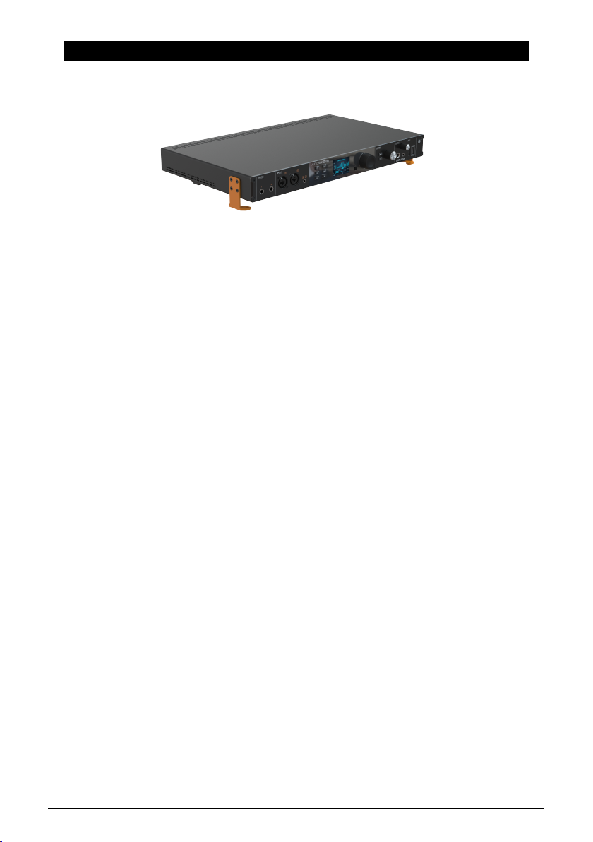
The two bright orange rack ears can be attached to the sides of the AudioFuse 16Rig to either
put it in a rack or place it on a desk or table. The screw holes are drilled so as to help you
avoid putting the ears on the wrong sides, but you should still be careful. Just remember
that the left ear has the Arturia logo on it!
The unit comes with mounting screws especially chosen for this purpose. Don't use other screws,
and carefully follow the directions in this manual, which match the ones printed on the inside of the box
lid. You don't want your new interface to sit all wobbly on your table, do you?
IMPORTANT: Note that the hole spacing is different between the left and right rackmount ears.
Therefore, please make sure that the Arturia "A" logo is on the left side of the interface.
Arturia - User Manual AudioFuse 16Rig - Setting Up The Hardware 5
Page 12
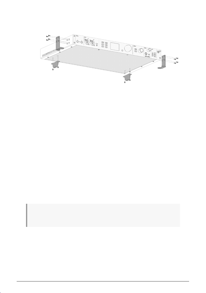
2.2.1. Configuring the AudioFuse 16Rig for Tabletop Use
AudioFuse 16Rig configured for tabletop use
In addition to the rack ears and screws, your AudioFuse 16Rig should also have a pair of
rectangular black plastic feet for the rear of the box, and a set of two semi-circular rubber
pads. You'll need these for tabletop use.
1. Stick the rubber pads onto the rack ears at the spot that will become the "feet".
This will keep the feet from scratching whatever you rest them on.
2. Attach the rubber pads so that the straight edge aligns with the 90º bend in the
rack ear, and then press the circular portion of the pad firmly onto the rack ear
in the direction of the two large screw holes. (See the diagram above or on the
box lid.)
3. Be sure to mount the rack ears so they are pointing under the AudioFuse 16Rig
(toward its center), not pointing away.
4. The two rear feet have tiny plastic guide pins that help them seat properly on the
bottom panel. Once you line those up with the guide holes in the bottom of the
unit, it will be easy to fasten the feet into place with the provided screws.
5. When the feet are properly installed, the AudioFuse 16Rig will be supported in
four places: the left and right rack ears (under the front) and the left and right
feet (under the back).
Now your unit is elevated above the tabletop and perfectly level and solid, so you could
place other gear on it, such as a small controller or tablet.
Keep in mind that the AudioFuse 16Rig does generate heat that needs to be able to escape the
chassis. Don't block the vents and leave room for air circulation, and don't stack another item that
generates heat on top of it (such as a laptop).
6 Arturia - User Manual AudioFuse 16Rig - Setting Up The Hardware
Page 13
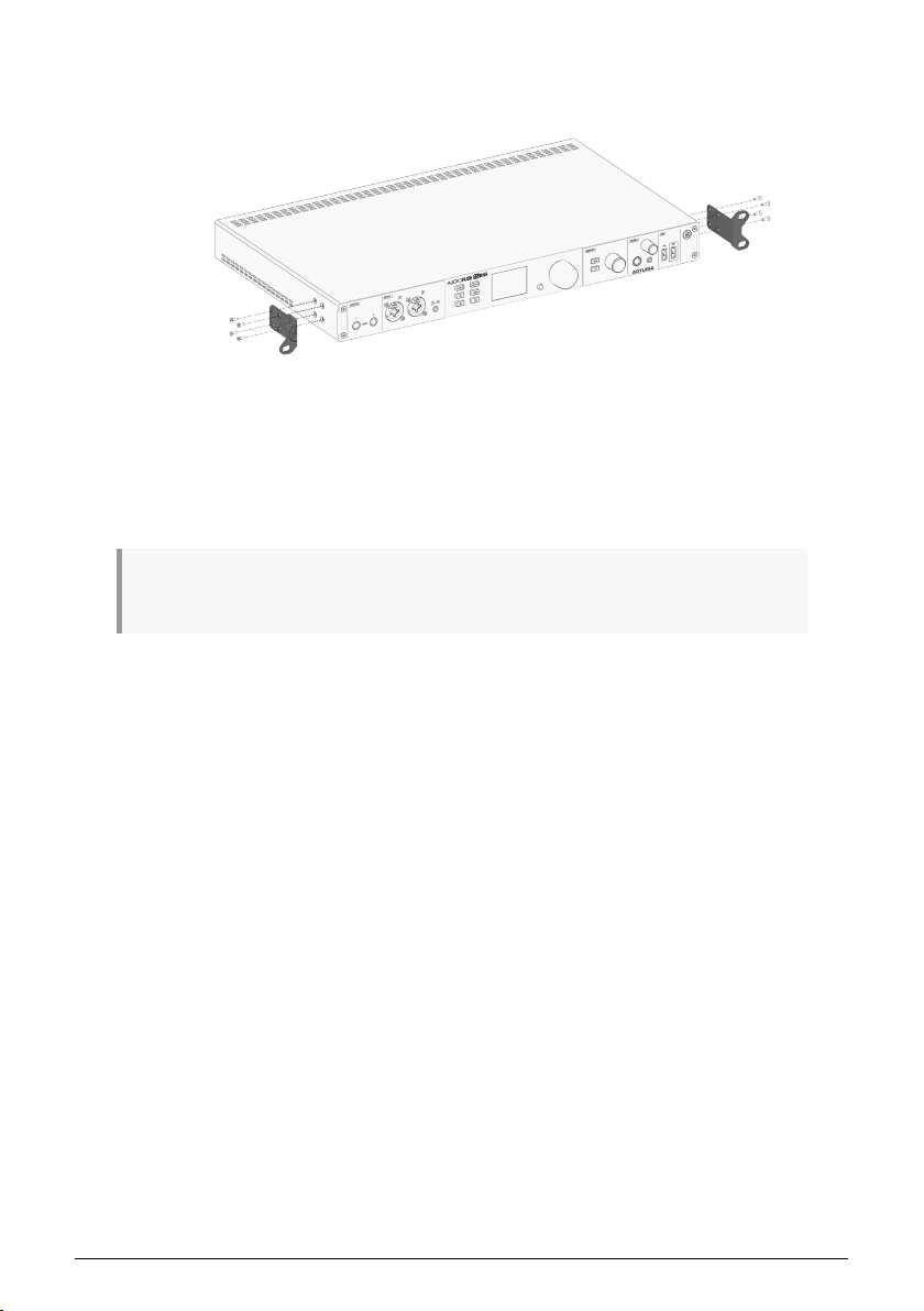
2.2.2. Rackmounting the AudioFuse 16Rig
AudioFuse 16Rig configured for rackmounting
Attach the rack ears in the configuration shown above, and the AudioFuse 16Rig is ready
to slot into your rack. In this configuration, you won't need the rear feet or rubber pads, so
leave them in the box in case you want to rack mount the unit some day.
We recommend rackmounting the AudioFuse 16Rig with an open rackspace above or below it, to
assist with keeping the unit cool during operation.
Arturia - User Manual AudioFuse 16Rig - Setting Up The Hardware 7
Page 14
3. REGISTRATION AND SOFTWARE SETUP
Now that we know a bit more about the AudioFuse 16Rig, it's time to get it ready to work
with your computer.
3.1. Registration
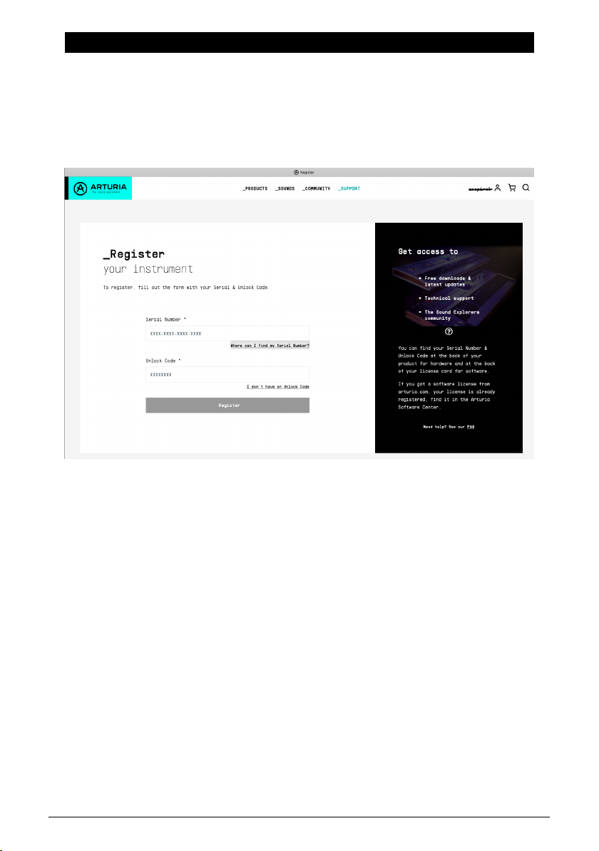
Once you've set up your hardware, the next part of the process is to register it with Arturia.
Have your registration card handy and go to www.arturia.com/register to log into your
Arturia account or create a new one. Then follow the online directions to register your unit.
Registering your AudioFuse 16Rig gives you access to a lot of important materials:
3.1.1. AudioFuse Control Center
You should download and install AudioFuse Control Center (AFCC) immediately. It's free, and is vital for the smoothest possible operation of your interface. It gives you access to controls that aren't available via the front panel, lets you lay out mixes, routings, and monitoring setups in a large and easy-to-use graphical interface. It will also notify you of firmware updates – and let you install the updates onto the hardware. See below for hints on a successful installation process.
3.1.2. AudioFuse Creative Suite
Great-sounding computer audio hardware deserves great-sounding computer audio software! The AudioFuse Creative Suite is a set of audio effects plug-ins, selected from Arturia's award-winning FX Collection, that are included with your purchase of a Fuse interface. These plug-ins include faithful emulations of vintage preamplifiers, compressors, time-based and modulation effects, reverbs, and more. Download and activate the Creative Suite plug-ins to jumpstart your music creation process.
8 Arturia - User Manual AudioFuse 16Rig - Registration and Software Setup
Page 15
3.1.3. User Guide
You don't need to register your AudioFuse 16Rig to download this manual, but the
registration process will help you make sure you have the latest edition.
3.2. Preparing the AudioFuse 16Rig to work with your
computer: macOS or Windows?
Once you've downloaded and installed AudioFuse Control Center, you'll need to check a
couple of settings on your computer to ensure the best communication with your interface.
3.2.1. macOS
Connect the AudioFuse 16Rig to its power su pply, plug it into your Mac with the appropriate
USB cable, and power it up.
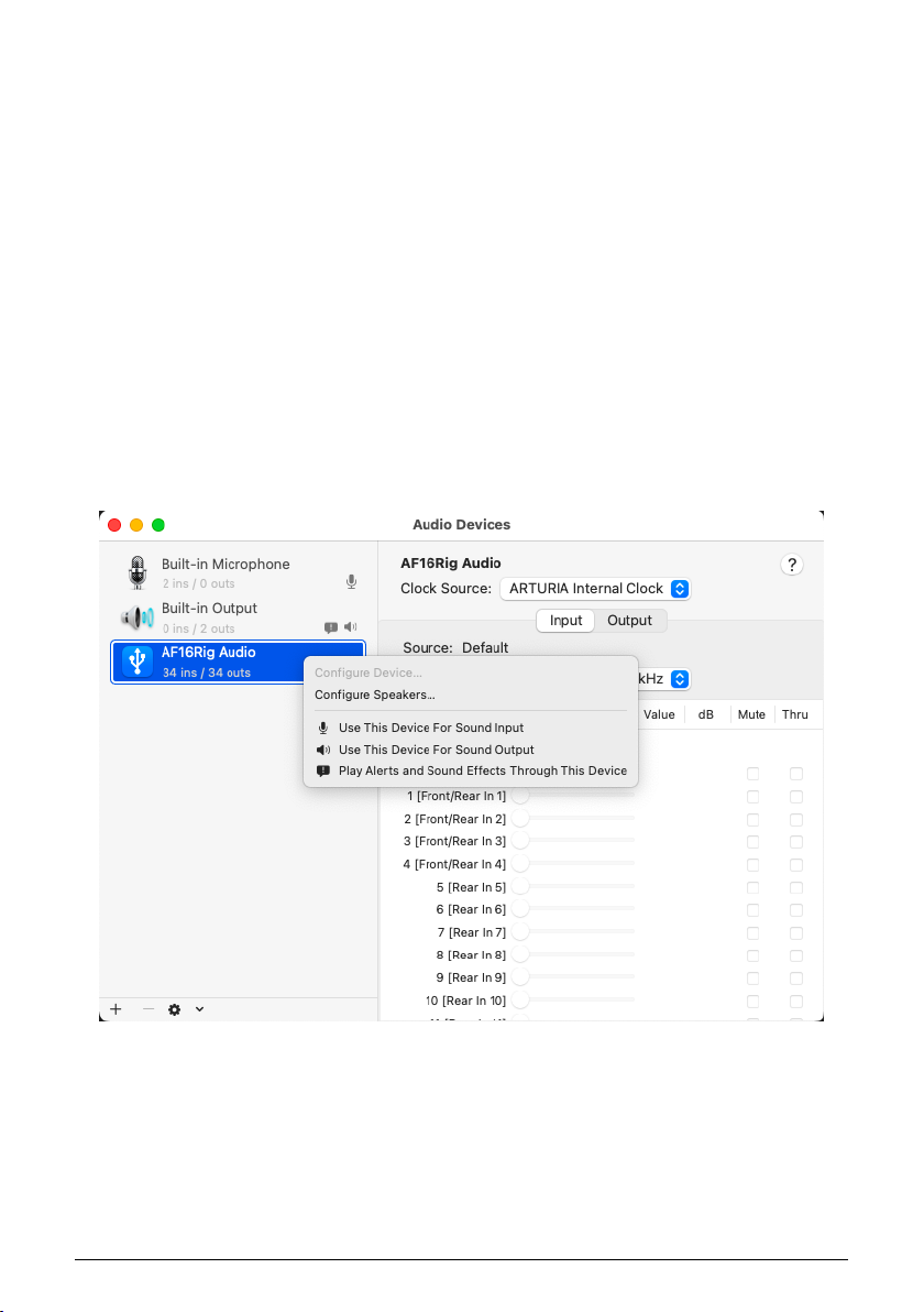
Launch Audio MIDI Setup (you'll find it in Applications/Utilities) and the AudioFuse 16Rig
should already be there.
To set up the AudioFuse 16Rig as your default audio device:
Audio MIDI Setup on macOS
1. Open the Audio Devices window and find "AF16Rig Audio" on the list of devices at left.
Arturia - User Manual AudioFuse 16Rig - Registration and Software Setup 9
Page 16
2. Highlight it, right-click on it, and a popup menu will allow you to choose it for Sound
Input and Sound Output. (You probably won't want to use it for Alerts and Sound Effects.)
3.2.2. Windows
When you install AudioFuse Control Center on your Windows PC, it will also install the
appropriate Arturia USB Audio Drivers. Once that's done, you can plug in and power up the
AudioFuse 16Rig.
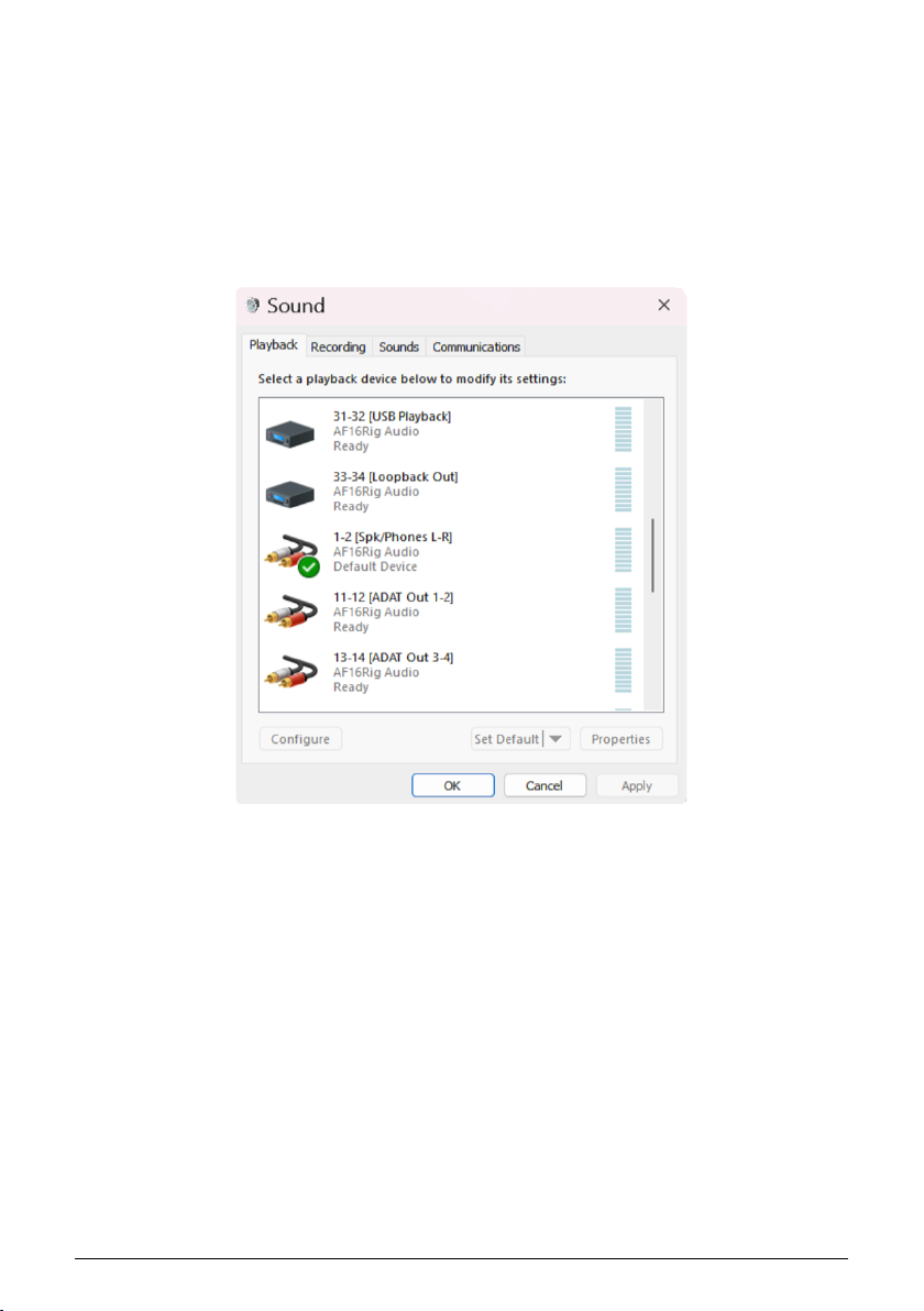
To set up the AudioFuse 16Rig as your default audio device:
Control Panel Sound Default Select on Windows
1. Go to the Control Panel and click Sound.
2. Find the AF16Rig in the device list and click Set Default and OK.
10 Arturia - User Manual AudioFuse 16Rig - Registration and Software Setup
Page 17
4. GETTING TO KNOW THE AUDIOFUSE 16RIG
As you've seen for yourself when you took the AudioFuse 16Rig out of the box, this interface
has a whole lot going on!
Let's take a tour around the AudioFuse 16Rig, and in the process we'll learn a lot about what
it can do.
4.1. The Front Panel
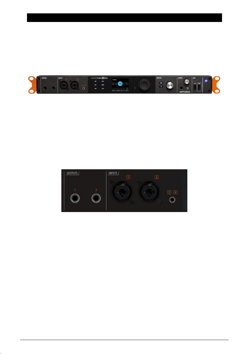
The AudioFuse 16Rig front panel
The AudioFuse 16Rig is designed not only for easy operation, but also for connecting gear in
a big hurry. While large professional studios will often have patchbays near the console so
that all their gear can be quickly connected, that's not practical for a home setup. (For one
thing, you'll need to buy twice as many cables as you have already!)
You're going to want to try out new synths and controllers and effects boxes all the time,
even when the bulk of your studio gear is permanently hooked up. Wouldn't it be nice if
there was an audio interface that makes switching gear in and out easy?
That's the idea behind the front panel connections of the AudioFuse 16Rig.
The Outputs and Inputs on the front panel
4.1.1. Outputs 3 & 4
On the far left of the front panel, there are a pair of TRS outputs that duplicate Outputs 3 & 4
on the rear panel. They can be used for extra headphone outputs, running a line-level signal
to external gear that's not normally hooked up, or
clean guitar signal back out to an amp or effects chain and recording the results back into
the interface.
reamplification
– the process of sending a
4.1.2. Inputs 1 & 2
Next we have a pair of inputs on combination TRS/XLR jacks. These can be used for linelevel or instrument-level signals from synths or guitars, or for high-quality mic recording via
built-in digitally-controlled analog preamps.
Arturia - User Manual AudioFuse 16Rig - Getting to Know the AudioFuse 16RIG 11
Page 18
One of the problems that musicians with more synthesizers than microphones discover
when buying audio interfaces is that they're often forced to pay for preamps they don't
need. The AudioFuse 16Rig gives you two excellent preamps, which is plenty for many users'
needs – and the rest of the budget is spent on a whopping 16 high quality line-level in puts.
You'll find the rest of the in puts on the rear panel – see below.)
There are also TRS jacks on the rear panel for Inputs 1 & 2. The AudioFuse 16Rig has an auto-sensing
feature, so the rear-panel jacks can remain plugged in at all times, and are automatically ignored when
the front-panel jacks are used. However, if you want to leave something plugged into the front panel as
well, those inputs have a REAR switch to manually route signals from the rear panel.
4.1.3. Inputs 3 & 4
For those occasions when you want to run audio from a miniature desktop synth or even a
smartphone into your mix, there's a 3.5mm minijack on the front panel that sends a stereo
signal to Inputs 3 & 4.
There is also a REAR button to activate the TRS jacks on the rear panel if you have devices connected
to both the front and rear in puts. It is accessible from the menu system in the hardware and from the
AudioFuse Control Panel software.
4.1.4. The Control Interface
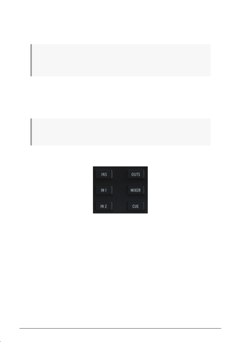
Direct Access Buttons
The center section of the front panel is where the AudioFuse's display and controls are
located.
Six front-panel buttons give you quick access to vital features. They are:
• INPUTS: Displays metering for all input signals
• IN 1: Instant access to controls for Input 1
• IN 2: Instant access to controls for Input 2
• OUTPUTS: Displays metering for all output signals
• MIXER: Takes you to the AudioFuse 16Rig's Main mixer
• CUE: Takes you to the AudioFuse 16Rig's secondary (Cue) mixer
12 Arturia - User Manual AudioFuse 16Rig - Getting to Know the AudioFuse 16RIG
Page 19
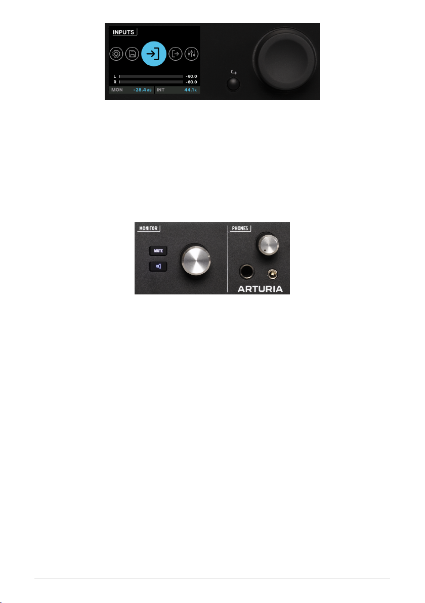
The display, encoder, and Back button
Next to these buttons is the color LCD that displays all relevant information while using the
AudioFuse 16Rig.
To the right is the main encoder for parameter control, which can be turned or pressed
(clicked). A small Back button next to it moves you back u p the hierarchy of screen menus
when needed.
4.1.5. Monitor and Phones
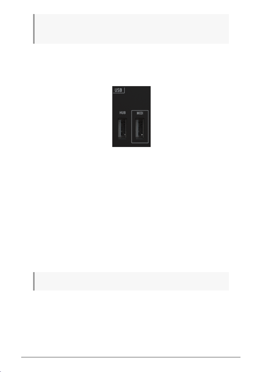
Monitor and Phones controls and front-
panel USB ports
Next is the Monitor knob, which controls the level coming out of the rear-panel Speaker outs.
It's accompanied by a MUTE button that when clicked, turns red and silences the speakers.
Below the MUTE button is a programmable function button. It lights in a different color for
each function, and blinks when activated. The functions are:
1. Mono (green): sums the left and right signals being sent to the speaker outputs.
This is useful if you need to verify mono compatibility or to check for phaserelated issues in your mix.
2. Dim (orange): turns down the speaker output by an amount designated in
the AudioFuse Control Center software. This is useful if you need to have a
conversation in the studio without stopping playback or losing your reference
loudness level while mixing.
3. A/B Speaker (blue): mutes the S peaker outputs and turns on a pair of B S peaker
outputs designated by the user – any analog output pair on the rear panel can be
designated for B Speaker use. However, we recommend using 5-6, 7-8 or 9-10,
and leaving 3-4 available since outputs 3-4 are mirrored on the front panel and
provide other useful functionalities.
Arturia - User Manual AudioFuse 16Rig - Getting to Know the AudioFuse 16RIG 13
Page 20
NOTE: The A/B S peaker function must be enabled for this feature to work. If the function is not
enabled, this button is ignored. You can enable the A/B Speaker function in AFCC's Configuration (gear
icon) menu, or on the hardware itself by going to Outputs > Monitor > A/B Configuration.
Next is the Phones knob, which provides control of the headphone outputs, provided on both
1/4" and 3.5mm TRS jacks.
4.1.6. Front Panel USB
Monitor and Phones controls and front-
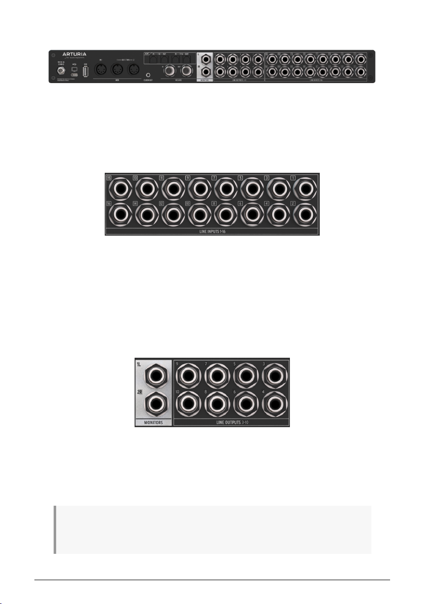
Finally we have two USB-A ports.
The first, labeled HUB, works as a powered USB hub for external devices you might need
to connect to your computer while you're working: external drives to load and save sample
libraries, control surfaces for your DAW, etc.
The second, labeled MIDI, is a USB Host port that allows you to plug in a controller that
only has a USB connector and no 5-pin DIN MIDI ports. They're getting more common every
day, and this jack lets you use them without having to run more cables to your computer
or an external USB hub. Unlike the HUB connection, this port remains active even when
the AudioFuse 16Rig is in standalone mode, giving you MIDI input and output without a
computer connected.
Note the small button in the upper right corner with the Arturia logo. This button turns the
AudioFuse 16Rig on and off. One push will power the unit on; to power off, hold the button
until the display says "Goodbye!" so the unit shuts down in a safe and controlled fashion. You
can also tap the button to bring up the AFCC software on the connected computer.
The button will be lit blue when in standalone mode and white if it sees a connected computer.
panel USB ports
14 Arturia - User Manual AudioFuse 16Rig - Getting to Know the AudioFuse 16RIG
Page 21
4.2. The Rear Panel
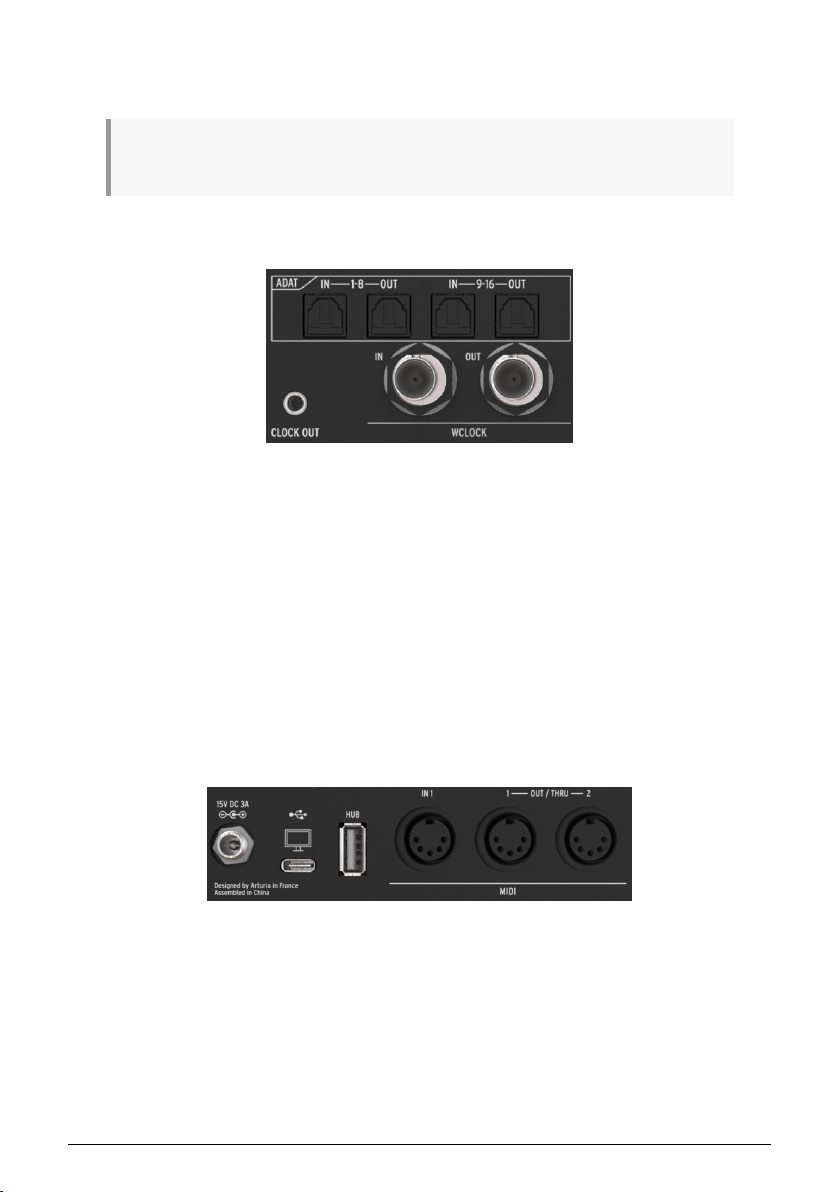
The AudioFuse 16Rig rear panel
The AudioFuse 16Rig's rear panel has a large complement of connectors. Here's a guide,
moving from
At the far right, you'll find 16 TRS balanced analog in puts with world-class A/D converters.
These can handle signal levels up to +24 dBu with the Pad switched on, and +12 dBu with
the Pad switched off.
Remember that the rear Inputs 1 & 2 are ignored if the front panel inputs are used, unless
the REAR function is selected. Inputs 3 & 4 work the same way.
right to left
.
4.2.1. Line Inputs 1–16
Rear panel audio inputs
4.2.2. Line Outputs 3–10 and Speaker Outputs
Rear panel audio outputs, with Speaker
To the left of the Line Inputs are 8 balanced analog line-level outputs. Any of these four pairs
of outputs can be sent to another set of speakers and controlled from the front panel if A/B
Speaker mode is engaged.
These outputs are all DC coupled. That means they are capable of not only playing audio, but
running DC control voltages to external modular synthesizers and other analog synth gear. This lets you
control your analog synths from your DAW with the right software!
Arturia - User Manual AudioFuse 16Rig - Getting to Know the AudioFuse 16RIG 15
outputs at left
Page 22
To the left of the Line Outputs and backed in white, the S peaker Outputs are TRS jacks that
should be connected to your primary set of monitors. Your DAW will see them as Outputs 1
and 2.
Note that if you've switched on the A/B Monitoring function, and switch to your alternate or "B"
speakers, these outputs are muted.
4.2.3. Digital Audio I/O
Rear panel ADAT and Word Clock ports
The AudioFuse 16Rig will grow with your setup, offering the ability to send and receive multichannel digital audio at high resolution. You can use these facilities to connect external
preamps (like the AudioFuse 8Pre), or route audio to and from any gear with ADAT optical
connections such as standalone A/D and D/A converters.
The four ADAT ports use optical Toslink connectors. They can provide either 16 channels of I/
O at 44.1 or 48 kHz, or 8 channels of I/O at 88.2 or 96 kHz.
Underneath are BNC connectors for Word Clock In and Out. They're internally terminated
so you don't have to add an external terminator when using them. These jacks assure that
all of your digital gear is following the same clock signal, to maintain the highest possible
fidelity.
4.2.4. MIDI, USB, and Power
Rear panel MIDI, USB, and power connections
The AudioFuse 16Rig has one MIDI In and a pair of assignable MIDI Out/Thru jacks, all on
5-pin DIN connectors. A 3.5mm jack next to MIDI Out/Thru 2 provides an analog MIDI clock
signal for use with certain analog synths, drum machines and modular synthesizers.
To the left of the MIDI jacks are a rear-panel USB-A port that acts as part of the interface's
built-in hub, a USB-C port that connects to the host computer for interface control and DAW
communication, and a locking connector for the AudioFuse 16Rig's power supply.
16 Arturia - User Manual AudioFuse 16Rig - Getting to Know the AudioFuse 16RIG
Page 23
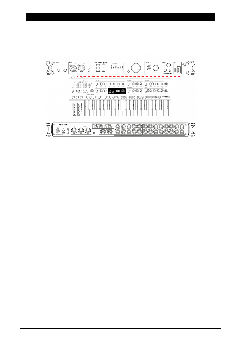
5. PUTTING YOUR AUDIOFUSE 16RIG TO WORK
Here are some common ways in which you'll use your AudioFuse 16Rig.
5.1. Recording line level devices
We'll start with the most common use case: hooking up
synthesizers and other keyboards, drum machines, samplers, beat production workstations,
etc. These are usually the "hottest" input signals you'll be working with, and shouldn't need
much in the way of added gain.
1. Connect your gear to any of the line inputs on the front or rear panel. Remember
that if you connect gear to the front panel inputs, the corresponding rear panel
inputs will be ignored unless you use the REAR function.
2. Press the INPUTS button to bring up the Analog Inputs page. Play each
instrument, one at a time, and watch the meters.
3. Ideally, the loudest parts of your performance should cause a channel's VU
meter to peak between -10 and -6dB.
4. Scroll to select the channel you want to adjust. Watch the numbers under the
meters; the currently selected channel will be white. Click the Encoder to select
that channel.
5. Set the gain on the channel to get the proper meter reading (the channel meter
is on the left of the screen). If your line-level device has a volume control, we
recommend you adjust the output level on the device itself, before increasing the
gain on the interface. This will get you the cleanest sound; use gain control on
the AudioFuse 16Rig only for devices with no level control or very weak output
signals.
6. If your sound source is so loud that it overloads the VU meter even at the lowest
gain setting, press the Pad button to switch on the 20dB input gain reduction.
7. You can also flip the phase of the input, stereo-link odd/even channel pairs (e.g.
5 and 6 or 9 and 10), and/or force the interface to use the rear panel inputs for
Channels 1–4 even if there's something plugged into the front panel inputs.
And there you go! Your instruments are ready to record. Please refer to your software's user
guide if you have any questions about how to record.
line level
devices. This includes
Arturia - User Manual AudioFuse 16Rig - Putting Your AudioFuse 16Rig To Work 17
Page 24
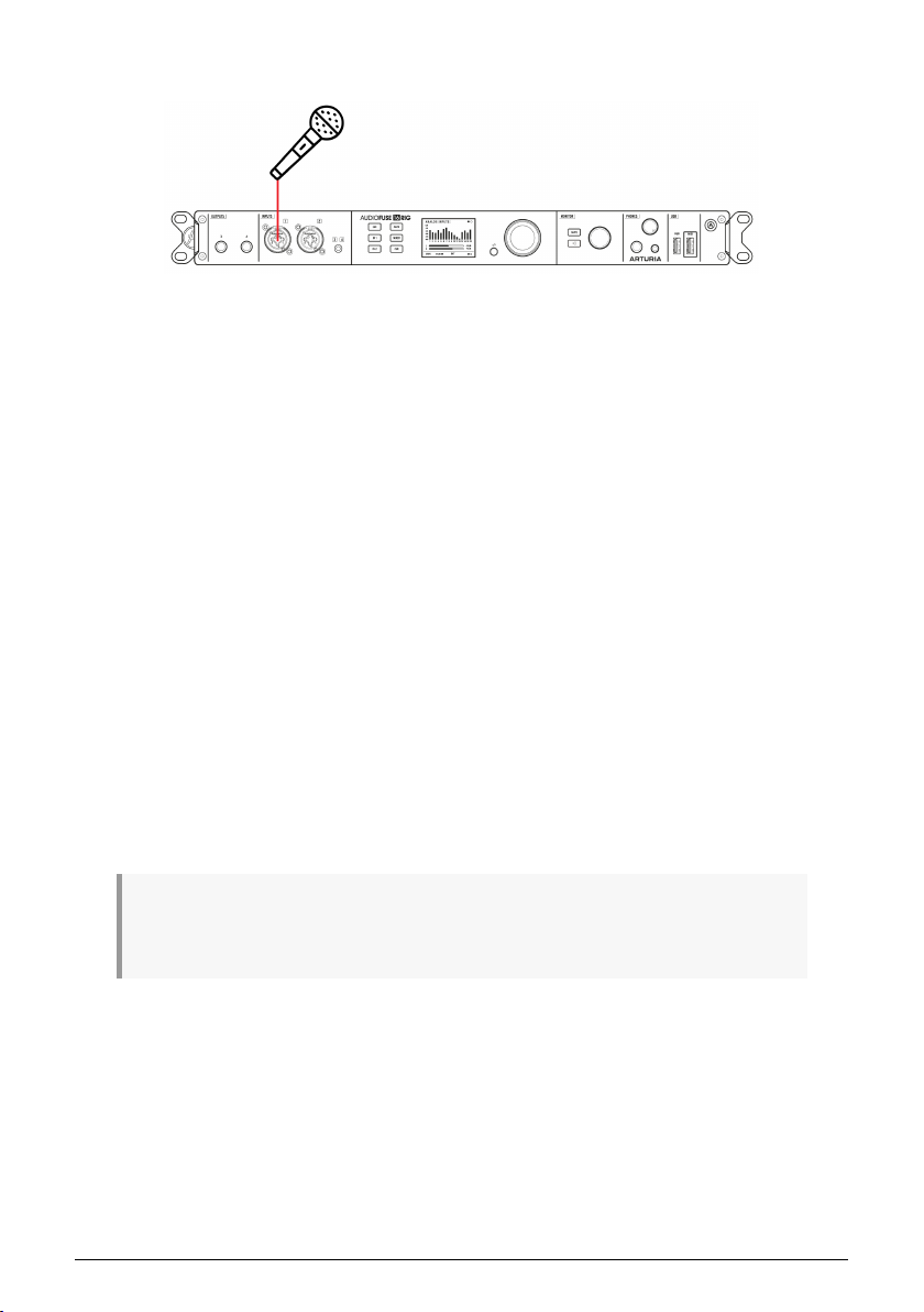
5.2. Recording a microphone
Microphones (especially ribbon mics) generate extremely weak signals, which are referred
to as
mic level
mic preamps on Inputs 1 & 2 have a lot of gain and very low noise!
That's it! The microphone input should be available in your music software and ready to
record.
. They require the most gain to be heard clearly, so it's a good thing that the
1. Connect your microphone to one of the mic inputs on the front panel.
2. AudioFuse 16Rig will auto-detect that you have connected an XLR cable and that
input channel will be given a 48V button in both the hardware and in AFCC.
Switch on 48V phantom power if your mic needs it.
3. Press IN 1 or IN 2 to immediately access the appropriate channel. If you've
connected an XLR cable, the input channel will now be labeled FRONT MIC rather
than ANALOG IN, and the channel in AFCC will have a microphone icon.
4. If your microphone requires phantom power, press the 48V button to switch on
phantom power.
5. Talk or sing into the mic while adjusting the gain. The loudest parts of your
performance should cause the channel's VU meter to peak between -10 and
-6dB.
6. If your sound source is so loud that it overloads the VU meter even at the lowest
gain setting, press the Pad button to switch on the 20dB input gain reduction.
7. If your sound seems weak or "phasey", try flipping the phase with the button
labeled Ø.
NOTE: If you click and hold the encoder while the interface is showing the display page for a
particular channel, the CLIP LED will be cleared. If you do this on the main INPUTS page, all CLIP LEDs
will be cleared. This is particularly important if you have the Clipping Reset Time set to "Infinite" in AFCC.
18 Arturia - User Manual AudioFuse 16Rig - Putting Your AudioFuse 16Rig To Work
Page 25

5.3. Recording a Guitar or Bass
Guitars, basses, and other instruments with magnetic or piezoelectric pickups run at
instrument level
level. In addition, the pickup needs to see a very high in put impedance, or its tone could be
compromised.
1. Connect your guitar or other instrument to either of the front panel inputs with a
2. AudioFuse 16Rig will auto-detect that you have connected a 1/4" cable and that
3. Press IN 1 or IN 2 to immediately access the appropriate channel. It will be
4. Scroll to the INST button and click it.
5. Play the instrument while adjusting the gain knob. The loudest parts of your
6. If your instrument is so loud that it overloads the VU meter even at the lowest
Your instrument is now set up to feed the clearest, cleanest signal to your software.
. Signal levels will be hotter than mic level, but usually not as hot as line
standard 1/4" cable.
channel in AFCC will add a button labeled INST. By default, channels are set to
receive a line-level signal; you'll need to click the INST button for instrument-level
use.
labeled FRONT LINE rather than ANALOG IN.
performance should cause the channel's VU meter to peak between -10 and
-6dB.
gain setting, press the Pad button to switch on the 20dB input gain reduction.
Arturia - User Manual AudioFuse 16Rig - Putting Your AudioFuse 16Rig To Work 19
Page 26
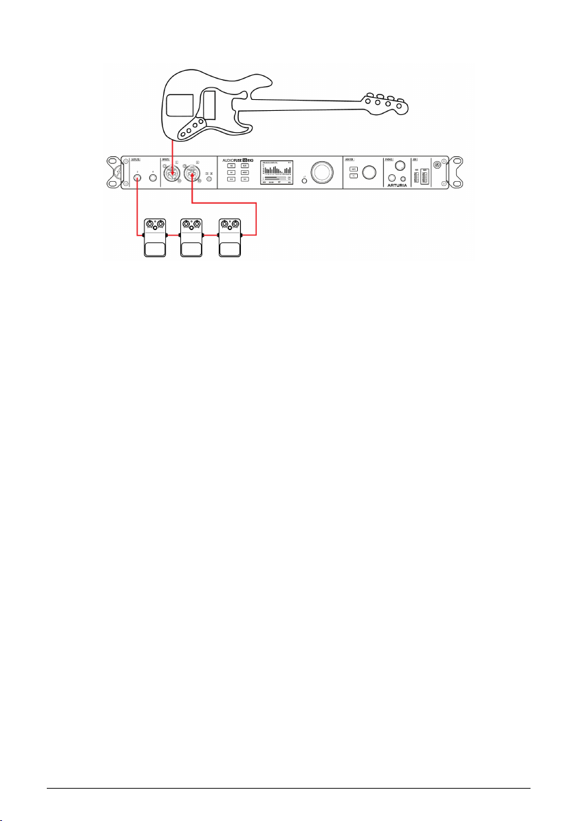
5.4. Reamping a Guitar or Bass
Reamplification
or "reamping" is a way to tweak the tone of a recorded track after the
fact. The guitar, bass, or other instrument signal is recorded as cleanly as possible, with no
effects or amplifier. Then, later on, that signal can be sent back out to a pedalboard or miked
amp. The engineer can now tweak the tone all they want – since the performance is already
recorded, the guitarist doesn't have to play it over and over.
The trick to reamping is that the signal out of the interface has to convince the pedals or
amp that it's coming from a guitar pickup. Therefore it has to present the right signal level
and output impedance. Commercial reamplification boxes (sometimes nicknamed "reverse
DI boxes") have been around for many years, but the AudioFuse 16Rig has the capability
built into the front panel outputs 3 and 4.
1. Record your guitar or bass part clean, as described above.
2. Connect a cable from one of the front panel outputs to your pedalboard or amp.
3. Press the OUTPUTS button. Scroll to select Output 3 or 4 and click to access the
Analog Out settings pages.
4. Scroll to the third page and use the dropdown menu to select Reamp. A button
will appear to let you lift the output ground if you hear hum.
That's all there is to it! You can now assign your DAW to play back your performance through
your pedals and amps, and tweak your tone to your heart's content.
20 Arturia - User Manual AudioFuse 16Rig - Putting Your AudioFuse 16Rig To Work
Page 27
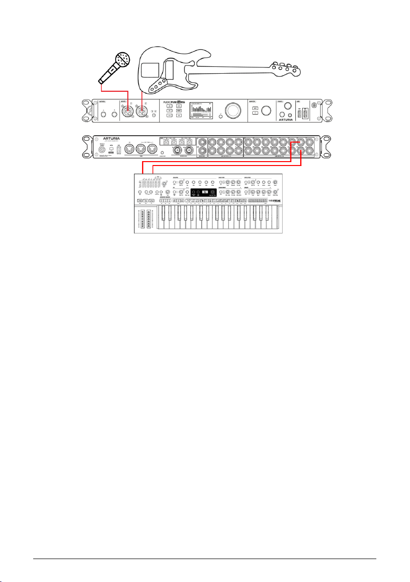
5.5. Creating a Mix
The AudioFuse 16Rig can combine signals with two different mixers: the
includes up to four
Main Mix in the same way you'd use any conventional mixer, while the Cue Mix can feed a
headphone amplifier so performers can hear "more me" as they play.
1. Connect and adjust in put levels for your line-level sources, microphones, and/or
guitars, as described above.
2. Press the MIXER button to access the Main Mix or the CUE button to access the
Cue Mix. (We'll talk about the Main Mix in the following steps, as the Cue Mix is
identical but has no Aux Sends.)
3. Scroll to the MAIN CHANNELS pages to select which inputs will be present in your
mix. The current in put will be highlighted in blue; press the encoder to select the
input and it will light u p solid white. Note that all in puts have the option of being
selected as mono channels or linked stereo pairs.
4. In addition to analog sources, there are selectors for ADAT inputs from the rearpanel ADAT inputs and USB playback channels from your recording software.
These can also be selected as mono inputs or stereo pairs.
5. Now, return to the MAIN MIXER page. You should see all of your added channels,
each with a fader level indicator, level meter, and Mute and Solo indicators, as
well as meters for the four Aux buses and the Main Mix on the right. If there are
more than 8 channels in your mix, subsequent channels will be shown on extra
pages after the first one.
6. Scroll to a channel to select it, and click the Encoder to enter its channel settings.
Select the parameter you want to adjust, click on it, edit it using the main
encoder, and click again to confirm and move on.
7. Repeat this process for all channels, and adjust the stereo level and Aux return
levels on the MAIN MASTER page.
Aux Sends
, and the
Cue Mix
, which does not. Typically you'd use the
Main Mix
, which
Arturia - User Manual AudioFuse 16Rig - Putting Your AudioFuse 16Rig To Work 21
Page 28
This method lets you adjust a mix on any or all channels from the front panel of the
AudioFuse 16Rig without a computer, and up to eight Main mixes can be saved and loaded
as Presets.
As you can imagine, this process can get pretty tedious. It's much faster and easier to set u p and
save Main and Cue mixes using the AudioFuse Control Center [p.8] software. Also, channel routings for
the various Aux and Mix outputs can only be set within AFCC.
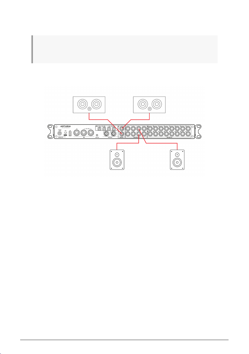
5.6. Using Two Sets of Speakers
It's quite common for studios to have two sets of monitor speakers set up at any given time.
In addition to the main set of monitors, a second set can be used as "check speakers" to
hear what the mix sounds like on, say, a car stereo or cheap home entertainment system.
Alternatively, a studio might have a very loud and bass-heavy PA set up to impress clients.
Whatever use you might have for a second set of speakers, AudioFuse 16Rig can easily
accommodate your needs.
1. Connect your primary speakers to the rear panel Monitor Outs.
2. Select any pair of rear panel outputs to feed your second set of speakers.
3. Press the OUTPUTS button, select MON, and click to enter the Monitor Settings
pages. Scroll to the third page, labeled A/B Conf.
4. Here you can activate or deactivate A/B switching as a function using the button
with the power symbol. The A/B button switches between the Monitor outs (unlit)
and the B Speaker outs (lit). The drop-down menu lets you choose which pair of
rear panel outputs will feed the B Speakers.
5. If you wish to make A/B switching a one-button affair, you can set up the frontpanel Monitor button to do this. To do this, enter the Settings section from the
carousel, and go to the Monitor Settings page. There, set the Monitor Button Mode
to "A/B Speaker".
22 Arturia - User Manual AudioFuse 16Rig - Putting Your AudioFuse 16Rig To Work
Page 29
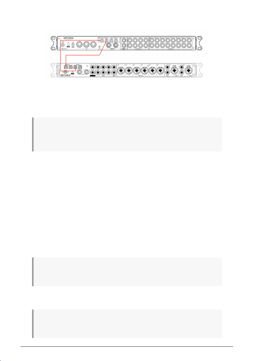
5.7. Connecting to ADAT Digital Audio Devices
The AudioFuse 16Rig can su pport up to 16 channels of ADAT digital I/O by using the four
optical Toslink connectors on its rear panel. Each port carries eight channels of audio in one
direction when working at 44.1 or 48k sampling rates. Digitally connected devices can be
synchronized through the ADAT connection itself or via the nearby Word Clock BNC ports.
Note: This section describes how to connect devices using only ADAT cables (i.e., audio and digital
sync signals are both transmitted together through the optical cable). For larger, more advanced studios
with lots of digital equipment, Word Clock synchronization may be required or preferred. This is covered
in the next section.
In the illustration above, we have an AudioFuse 16Rig (top) connected to an AudioFuse 8 Pre
(bottom). ADAT optical cables carry digital audio to/from each unit. Synchronization signals
are also carried along the cable.
When working with digitally connected audio devices, it’s vital that there is only one clock
source. Having all devices synchronized to one primary clock prevents clicks, pops, and
other audio artifacts that can arise from slightly mismatched clocks.
In this setup, the AudioFuse 16Rig acts as the primary reference clock and so its “Clock
Source'' parameter is set to “Internal.” As a result, AudioFuse 8Pre must have its own clock
( the “Sync” parameter on its front panel) set to “ADAT'' so that it receives and synchronizes
itself to clock information coming from the AudioFuse 16Rig.
To do this:
1. Connect your digital audio devices to each other using the rear panel ADAT ports. The
output(s) of the AudioFuse 8Pre connect to the input(s) of the AudioFuse 16Rig and vice
versa.
Note: Each device has two input ports and two output ports. In this example, the second port is only
necessary if you are working at higher sampling rates (88.2 or 96k). Since we are working at standard
(44.1 or 48k) sampling rates, only the first input and output ports are used.
2. Ensure that the clock source of AudioFuse 16 Rig is set to “Internal” while the clock source
of AudioFuse 8Pre (labeled “Sync” on the front panel) is set to “ADAT”.
Note: If AudioFuse 16 Rig is connected to a computer, the Clock Source and Sample Rate parameters
in the hardware may be grayed out. If so, you need to change the Clock Source and/or Sample Rate
parameters from the AFCC or your DAW.
Arturia - User Manual AudioFuse 16Rig - Putting Your AudioFuse 16Rig To Work 23
Page 30
At this point, the two devices are digitally connected and properly synchronized. In your
music software, record-enabling the AudioFuse 16Rig’s ADAT in puts 1-8 will let you capture
the output of AudioFuse 8Pre and all its pristine preamps.
5.8. Working with multiple ADAT Devices using WordClock
Sync
The previous section described how to connect two digital devices to each other using ADAT
optical cables only. In that example, digital synchronization was established through the
same optical cable that carries audio signals.
However, larger more advanced studios with many pieces of digital equipment may need
to use Word Clock to sync devices together. This example is similar to the first example
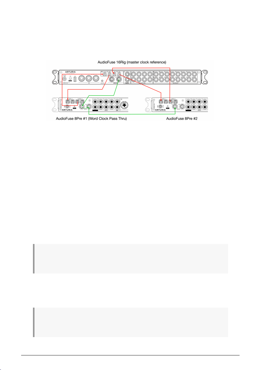
above except that we now have two AudioFuse 8Pre units connected to the AudioFuse 16Rig
through ADAT. This greatly expands the already impressive I/O capabilities of the 16Rig by
adding 16 channels of pre-amplified inputs and 16 additional analog outputs.
In this setup, it is not possible to synchronize both devices through ADAT cables alone
because AudioFuse 16 Rig’s second set of ADAT ports cannot send or receive synchronization
data (only the first set of ADAT I/O ports can send or receive sync signals). This is not a
problem, however, since we can use Word Clock to synchronize the three devices. In fact,
Word Clock can be used to synchronize as many digital devices in your studio.
Like the previous example, this setup will use optical cables to carry audio signals to and
from each 8Pre expansion. Unlike the previous example, we will use two BNC cables to carry
the sync data among the devices. The optical audio cables are shown above in red while
the BNC cables are shown in green.
Note: Each AudioFuse 8Pre has two input ports and two output ports. The second port is only
necessary if you are working at higher sampling rates (88.2 or 96k). In this example, we are working at
standard (44.1 or 48k) sampling rates so only the first input and output ports should be used.
How to set up the Word Clock sync:
1. AudioFuse 16Rig is our primary reference clock and so we must set its “Clock Source”
parameter to “Internal.”
Note: If AudioFuse 16 Rig is connected to a computer, the Clock Source and Sample Rate parameters
in the hardware may be grayed out. If so, you need to change the Clock Source and/or Sample Rate
parameters from the AFCC or your DAW.
24 Arturia - User Manual AudioFuse 16Rig - Putting Your AudioFuse 16Rig To Work
Page 31
2. We then configure the first AudioFuse 8Pre to synchronize itself to the AudioFuse 16Rig
through the Word Clock connection by setting the AudioFuse 8Pre’s “Sync” parameter (on
the front panel) set to “Word.”
3. Next, let’s switch on the “Pass Thru” function on the first AudioFuse 8Pre. This is done
through the AFCC under Device Settings (Gear Icon) > Audio Settings > Pass Thru. Switching
this function on passes the incoming clock signal directly out of the first AudioFuse’s Word
Clock output letting you “daisy chain” other devices that require clock synchronization.
4. Next, let’s connect the Word Clock output of the first 8Pre to the Word Clock input of the
second AudioFuse 8Pre.
5. Finally, ensure that Word Clock Termination is switched ON for the second AudioFuse
8Pre. This is done through AFCC under Device Settings (Gear Icon) > Audio Settings > Clock
Termination. This parameter must be set to “75 Ohms (On)”
At this point, the three devices are digitally connected through ADAT and properly
synchronized through Word Clock. In your music software, record-enabling the AudioFuse
16Rig’s ADAT inputs 1-8 and 9-16 will let you capture the pristine preamplified output of both
AudioFuse 8Pres.
Note that this section only covers the basics of working with Word Clock and there are other
(more advanced) ways of synchronizing digital devices to each other. To learn more about
this topic, we recommend taking a look at this article.
5.9. Connecting MIDI and USB devices
AudioFuse 16Rig lets you connect both MIDI and USB devices. MIDI inputs and outputs
let you connect MIDI synthesizers, drum machines, control surfaces, etc. to the AudioFuse
16Rig to play and record MIDI data. The interface also has multiple USB ports for connecting
extra hardware like USB MIDI controllers, software copy protection keys, memory sticks,
and more.
1. Connect any MIDI devices you wish to use to the rear-panel 5-pin DIN MIDI IN and dual
MIDI OUT/THRU ports.
2. Connect the AudioFuse 16Rig to your host computer via the rear panel USB-C port.
Arturia - User Manual AudioFuse 16Rig - Putting Your AudioFuse 16Rig To Work 25
Page 32
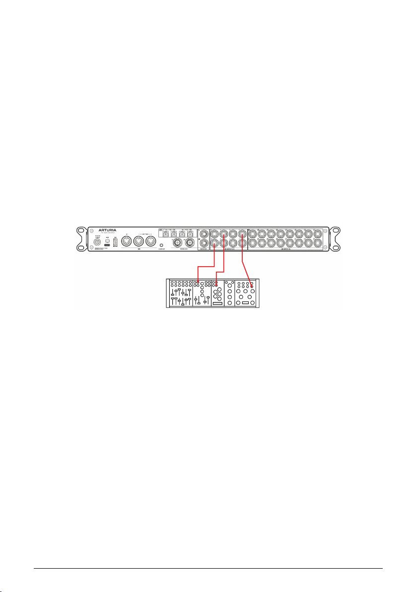
3. If you would like to connect multiple USB devices to your computer but you're short
on USB-A ports, use the front and rear panel HUB connectors to add single USB devices or
powered USB hubs. This is especially handy for modern laptops that might have only a few
USB-C ports to spare, and might have no USB-A ports at all.
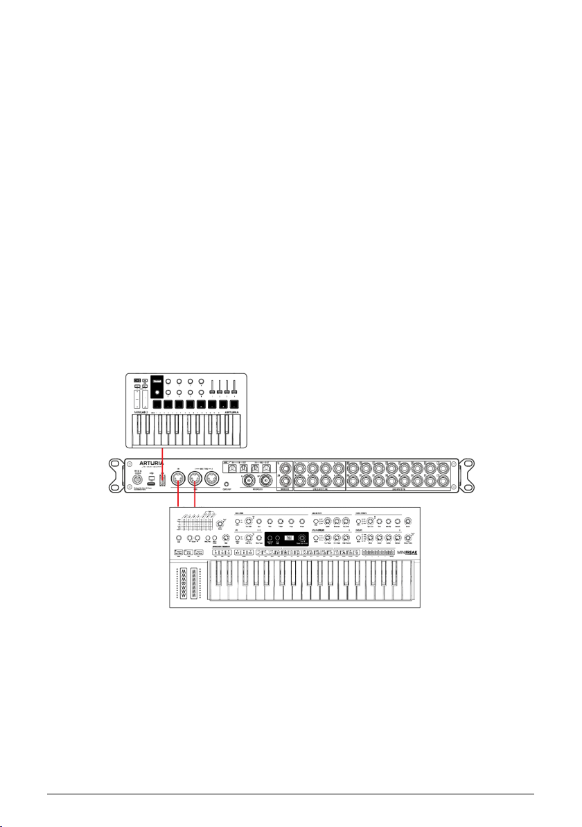
4. The front panel also has a MIDI USB-A port. If you connect a USB MIDI device like
a keyboard or control surface to this port, it will operate the AudioFuse 16Rig and any
connected MIDI gear even when the interface isn't connected to a computer. This can
be useful for users that are interested in DAWless jamming or performing live on stage
without a laptop. Audio and MIDI always flow through the interface, even if a computer isn't
connected. In fact, you can control AudioFuse 16Rig's Main mixer using MIDI messages from
any connected controller.
5. Click on the MIDI menu to select how the AudioFuse 16Rig will route and respond to
MIDI.
If you're going to be recording and playing back MIDI via recording software, consult that
software's documentation to learn how.
5.10. Using the AudioFuse 16Rig as a Control Voltage
source
AudioFuse 16Rig's outputs 3–10 are DC Coupled. This means these outputs are designed to
output not only audio signals but also inaudible "control voltage" signals that are understood
by analog synthesizers.
Using the DC coupled outputs and specific DAW plug-ins such as Ableton Live's CV Tools,
you can easily output CV signals from your DAW to control your modular and semi-modular
synthesizers, such as Arturia's MiniBrute.
No configuration is needed in the AFCC software to do this, but you may need to adjust the
output level and use specific mono cables to connect the AudioFuse 16Rig's outputs to your
synths' CV inputs.
26 Arturia - User Manual AudioFuse 16Rig - Putting Your AudioFuse 16Rig To Work
Page 33
6. GETTING AROUND
Now it's time to dive in and learn how to use the AudioFuse 16Rig. The chapters after this one
will serve as a step-by-step reference to all of the hardware's functions.
But first, it would help to learn a few basics about how to navigate the front-panel interface
controls, and some of the most important parts of the interface's functions and menu
structure.
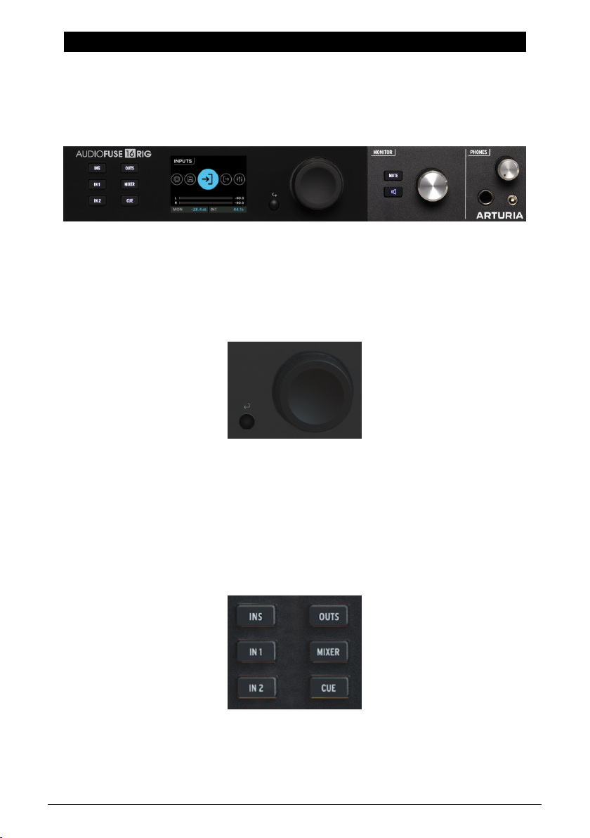
The physical controls on the front panel
6.1. Physical Controls: How do I get from here to there?
6.1.1. The Encoder and Back Button
The Encoder controls nearly everything on AudioFuse 16Rig.
Some terminology: You
to move through options on a page, and press (
The small Back button is below and to the left of the Encoder. Press it to cancel a current
operation or to step back one level in the menu hierarchy.
turn
the encoder to find the page or function you want,
click
) it to turn a function on or off.
scroll
with it
6.1.2. Quick Access Buttons
These buttons let you access the most commonly needed functions in your usual workflow.
They include:
• INPUTS (INS): the Analog Inputs metering screen
Arturia - User Manual AudioFuse 16Rig - Getting Around 27
Page 34
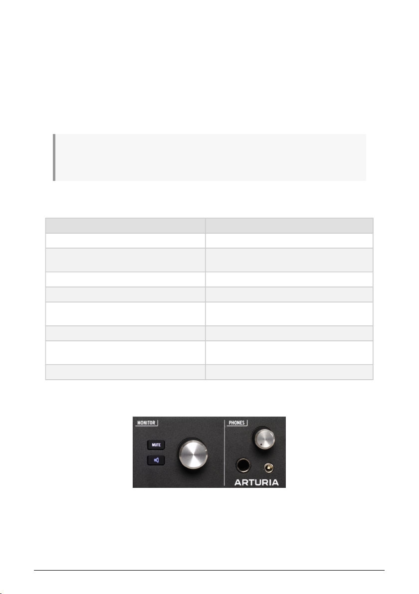
• IN 1: Controls for Analog Input 1
• IN 2: Controls for Analog Input 2
• OUTPUTS (OUTS): The Analog Outputs metering screen
• MIXER: The Main Mixer screen
• CUE: The Cue Mixer screen
Note that some of these screens are only the first of several pages (see below) of functions.
In those cases, the button takes you to the first (and most commonly needed) page.
If you turn the Encoder while holding down the INS, OUTS, MIXER, or CUE button, the display will
immediately jump to the next page in that menu rather than scrolling through all the options on that
page. This is a big timesaver!
6.1.3. AudioFuse 16Rig Hardware Shortcuts
Shortcuts Results
Long Press MAIN Knob Reset clip indicators
INS / OUTS / MIXER / CUE + MAIN Knob
Monitor Button + MAIN Knob Set Monitor Button Function
IN1 / IN2 + MONITOR Knob Set Input 1 / 2 Preamp Gain
INS / OUTS + MONITOR Knob on a specific Input /
Output view
MIXER / CUE + MONITOR Knob on Mixer / Cue view Change the Mixer / Cue Master Volume
MIXER / CUE + MONITOR Knob on Mixer / Cue
channel view
Double-click Back button Return to main menu
Quick navigation between subpages of INS / OUTS /
MIXER / CUE
Change the current input / output gain
Change the current channel gain
6.1.4. The Mute and Monitor buttons
MUTE button, Monitor button, and Monitor
28 Arturia - User Manual AudioFuse 16Rig - Getting Around
knob
Page 35
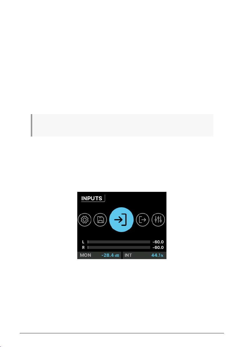
The Monitor knob controls the level coming out of the rear-panel Speaker outs (Or the B
Speaker outs, if A/B Speaker monitoring is enabled). It's accompanied by a MUTE button
that turns red when in use.
Below the MUTE button is a programmable Monitor button with a speaker icon. It is lit in
a different color for each of the functions that it can perform, and blinks bright/dim when
activated.
You can assign the button to any of the following three options:
1. Mono (green): sums the signals of Left and Right outputs and sends them to both
speakers.
2. Dim (orange): turns down the speaker output by a designated amount that can
be set in the AudioFuse Control Center application.
3. A/B Speaker (blue): mutes the Speaker outputs and switches on a pair of rearpanel analog outputs designated by the user – any analog output pair on the rear
panel can be designated as the B Speaker output.
Remember that the A/B Monitoring functionality must be switched on for this third option to work.
Otherwise, the button is ignored.
6.2. Screen Layout: what will I see when I get there?
6.2.1. The Carousel
This is the top level of the menu hierarchy. You can recognize it by the large circular icons.
If you're not seeing this (because you're on a different screen), just double-click the Back
button to bring you back to the Carousel.
The Home screen
Once on the Carousel, you can turn and click the icon for the function
access. These are represented on the Home screen by large icons and pop-up labels. They
will loop around to the beginning if you keep scrolling – like a carousel (merry-go-round).
The seven menus include:
• INPUTS: Metering and controls for the analog and digital inputs.
• OUTPUTS: Metering and controls for all analog and digital outputs.
Arturia - User Manual AudioFuse 16Rig - Getting Around 29
Menu
that you want to
Page 36
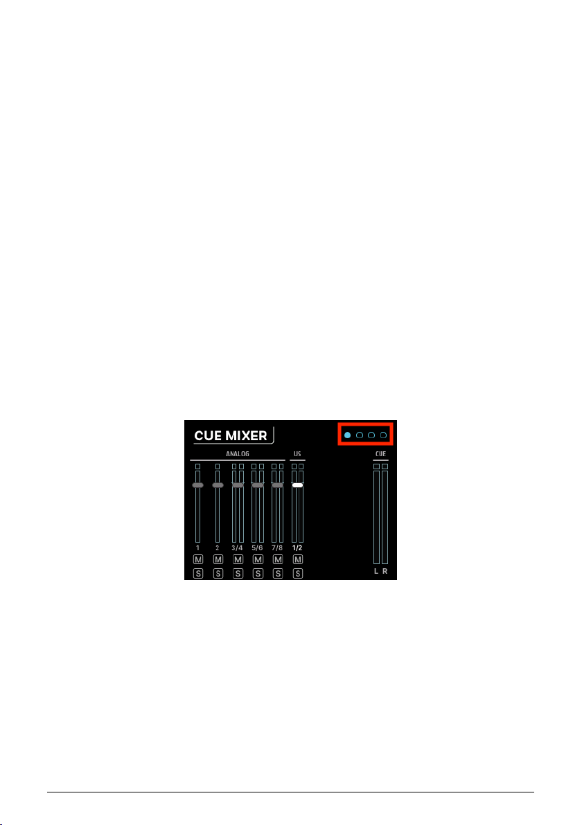
• MIXER: Metering and controls for the main Mixer, and to enable/disable channels
as needed.
• CUE: Metering and controls for the Cue Mixer, and to enable/disable channels as
needed.
• MIDI: Settings for MIDI input and output ports and routing, as well as a
comprehensive MIDI Activity monitor.
• SETTINGS: Clock, Monitor, and global preferences, as well as a System Info page
to show basic information about your particular AudioFuse 16Rig's hardware.
• PRESETS: Controls to save and load presets. There are 8 slots available.
6.2.1.1. Information Displayed on the Carousel
There are certain bits of information that are always visible at the bottom of the Carousel
screen:
• Meters for the Main outputs, with levels shown in dB
• Level setting for the Monitors (set with the Monitor knob)
• Clock source and sample rate
6.2.2. Pages
Many menus have multiple
pages
. These are indicated by small circles at the top right of the
screen.
Page icons
The number of circles naturally indicates the number of pages in that section, and the page
you're currently on is highlighted. In most cases, if you scroll past the last page, you will be
taken to the first page.
30 Arturia - User Manual AudioFuse 16Rig - Getting Around
Page 37
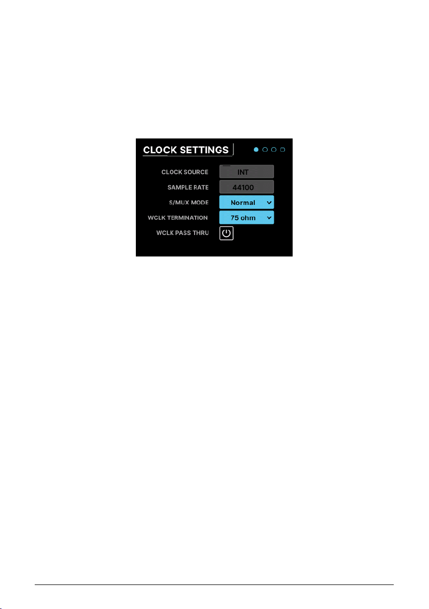
6.2.3. Scroll, Select, Activate
Once you're on the page you want, use the Encoder to scroll to the function you want to
work with. Then click to change it.
6.3. "Why is this function greyed out?"
Sometimes you'll run into a function that you can't select. This isn't a bug! The interface is
smart enough to know when a feature can't be used, and will tell you that by making it
inaccessible.
Parameters on a typical screen page
The most obvious example is Inputs 1 & 2. If nothing is plugged into one of the front panel
inputs, none of the functions specific to that input will be available. For example, if you
connect an XLR cable to the front panel input, a 48V switch will appear. If there is no mic
connected, that button will not be shown since there is no need for it.
6.4. Don’t forget the software!
Remember that all of these functions and more are available in the AudioFuse Control
Center software, in a neat graphical interface with instant visual feedback. While we
recommend that you read the software's user manual, you will find that many of the
features there are self-explanatory once you've learned your way around the hardware.
Arturia - User Manual AudioFuse 16Rig - Getting Around 31
Page 38
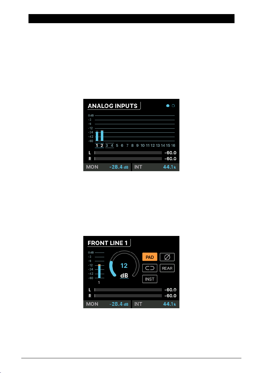
7. MENUS AND FUNCTIONS
The AudioFuse 16Rig's Carousel screen gives you access to seven different sets of functions.
In this chapter, we'll go through them one by one, and show which functions are available
on each page.
7.1. INPUTS
7.1.1. ANALOG INPUTS / ADAT INPUTS
When you click on the INPUTS icon or press the front panel INPUTS button, you're taken to the ANALOG INPUTS page:
Scrolling from left to right highlights each channel. When you get to the end, the view shifts
to the next page, which is ADAT INPUTS.
For all analog inputs, you can click on the number of the channel you want to edit
(highlighted in white). The second page displays incoming ADAT levels, and is there for
visual feedback only (it does not have any editable parameters).
7.1.2. ANALOG IN / FRONT LINE / FRONT INST / FRONT MIC
The screen can appear in 4 ways
depending on what's plugged in. This one
32 Arturia - User Manual AudioFuse 16Rig - Menus and Functions
is for the FRONT LINE.
Page 39
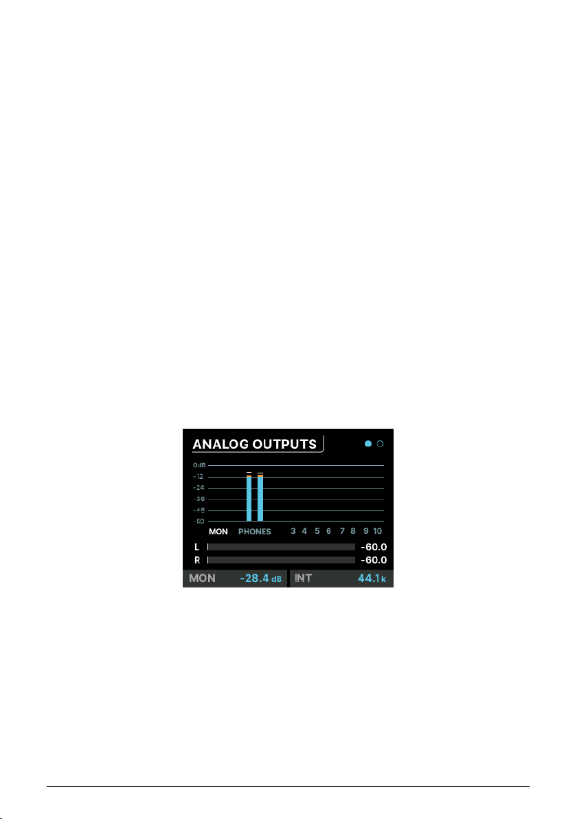
Each input channel page has the following features:
• Level meter
• Gain knob
• Buttons to activate or deactivate
◦ Pad
◦ Phase Invert (Ø)
◦ Stereo Link (chain link icon)
Depending on the channel you're looking at, there may also be other options offered:
• Front panel XLR channels also have a button for 48V Phantom Power
• Front panel 1/4" channels also have a button for Instrument Level (INST). This
sets the jack's in put impedance to 1 million Ohms, which assures that a guitar
or bass plugged into the front jack will not have the tone of its magnetic
pickups adversely affected by the interface. If you're recording a guitar, bass, or
electric piano into one of these jacks, the INST setting will assure you the most
transparent tone.
• Inputs 1–4 have a REAR button, which overrides the front panel in put in favor of
the rear-panel one. This lets you keep different inputs plugged in on the front and
back, and easily switch between them as needed.
7.2. OUTPUTS
When you click on the OUTPUTS icon or press the front-panel OUTPUTS button, you're taken to the ANALOG OUTPUTS page:
Scrolling from left to right highlights each output channel:
• MON indicates the Main Monitor output
• PHONES indicates the Phones output
• Numbers 3–10 indicate those rear panel outputs
Click on the name or number of the channel you want to edit (highlighted in white).
Arturia - User Manual AudioFuse 16Rig - Menus and Functions 33
Page 40

If a pair of outputs has been designated as the B Speaker pair, there will be a box around those two
channels, and clicking on them will bring up the A/B CONF page (see below).
7.2.1. MONITOR
Clicking on MON accesses the three MONITOR pages:
• The first page has a Gain knob (which is set with the front-panel MONITOR knob)
and buttons for the Mute, Dim, Mono, and A/B functions. Note that A/B will be
greyed out if the A/B function hasn't been switched on, which is done on the third
page as explained below.
• The second page has indicators showing which signals are being sent to OUT 1
and OUT 2.
• The third page is the A/B CONF (configuration) page. This page has a button to
turn A/B capability on or off, a button to switch between A and B if the function
is activated, and a drop-down menu to select the output pair that will feed the
B speakers. There's also a Trim knob for adjusting the B Speaker level to match
that of the Main Monitors.
7.2.2. PHONES
Clicking on PHONES accesses the three PHONES pages:
• The first page has a level meter and Gain knob for the Phones output signal. This onscreen parameter can be set with the front-panel PHONES knob.
• The second page has indicators showing which signals are being sent to the
headphones (OUT 11-12).
• The third page has a drop menu that lets you adjust the impedance of the
headphone output to match whatever headphones you happen to be using.
Setting this appropriately means you can use low, standard, and high impedance
headphones with ease.
7.2.3. ANALOG OUT 3 & 4
Analog Outputs 3 and 4 offer more capabilities than the other analog outputs. They are
available not only from the rear panel, but also from two jacks on the front panel that can
be set to several different functions that you'll find handy when working with external gear.
Clicking on Output 3 or 4 accesses three ANALOG OUT pages, all of which have output
metering:
• The first page has a Gain knob and a Stereo Link button
• The second page has an indicator showing which signal is being sent to that
channel's OUT jack.
34 Arturia - User Manual AudioFuse 16Rig - Menus and Functions
Page 41
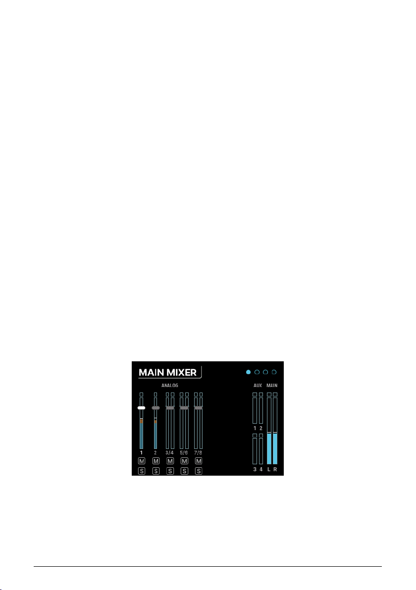
• The third page has a drop-down menu that lets you select what the front-panel
OUTPUT jack will transmit. Options are:
◦ Line: A conventional line-level output.
◦ Reamp: Sends the chosen source out through the front-panel output
at the appropriate level and impedance to feed a pedalboard or
amplifier for reamplification.
◦ DirectThru: Creates a true zero-latency connection from the front-
panel INPUT jacks 1 and 2 to the OUTPUT jacks 3 and 4. This is
important if you want to record a clean guitar signal to your computer
while also playing through your pedals and amp; this connection taps
into your cable run without introducing latency that can affect your
playing.
◦ AltPhones: Converts each output on the front panel into its own stereo
headphone jack. These outputs must share the same source (i.e., they
must mirror each other and you can not have separate things playing
from output 3 and 4), and their output level is set using the Gain knob
on page 1. However, the AltPhones do not have to mirror the main
headphone outputs of AudioFuse 16 Rig. You can set their source in
the Routing Matrix.
7.2.4. ANALOG OUT 5–10
Clicking on any other channel number accesses the two ANALOG OUT pages, both of which
have output metering:
• The first page has a Gain knob and a Stereo Link button
• The second page has an indicator showing which signal is being sent to that
channel's OUT jack.
7.3. MIXER
Clicking on the MIXER icon, or pressing the front panel MIXER button, takes you to the MAIN MIXER page.
Each channel in the mix has its own indicators for level, mute, and solo. There are also
meters for the Aux sends and L/R Main mix. Analog channels come first, then ADAT
channels, then USB channels.
If there are more channels in the mix than there is room on the screen, scrolling to the right
will move you to the next screen and more channels.
Arturia - User Manual AudioFuse 16Rig - Menus and Functions 35
Page 42
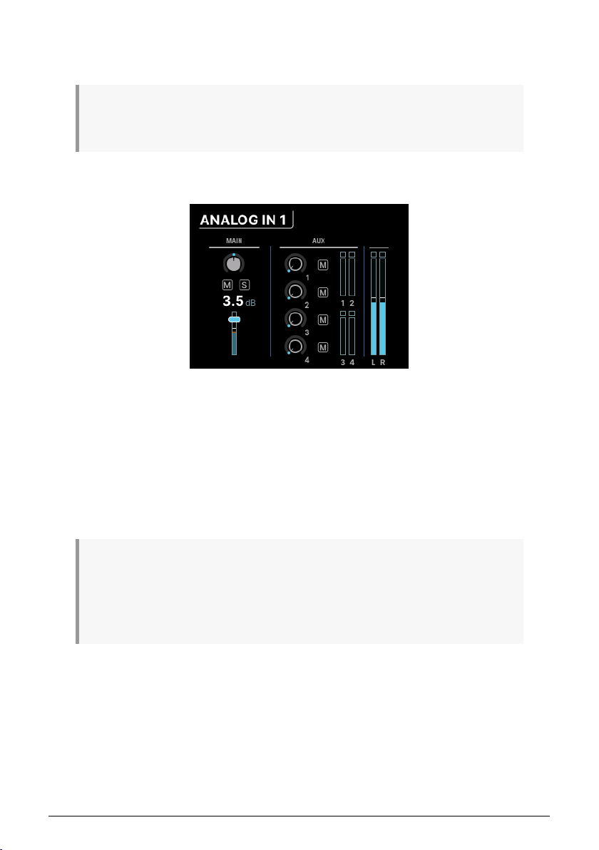
Note that the only clickable items in this view are the channel selectors. If you want to
change something like volume, mute or solo, click on any channel number to select it for
adjustment.
If the mixer appears empty, it's because no channels have been added yet. You can add channels
by going to the MAIN CHANNELS selectors (pages 3 and 4 in the MIXER section) and adding whichever
channels you would like to have available in the mixer.
7.3.1. MIXER CHANNEL SETTINGS
These screens are labeled by the input type and channel numbers, e.g. ANALOG 3–4 or USB
5-6.
On the left, you'll find the usual channel fader controls: pan, mute, solo, and fader level.
If two channels have been stereo linked, there will be two pan controls for individual
adjustment.
On the right is the Aux section, where the send amount and muting for the four Aux sends
can be adjusted. Finally there are meters for the Auxes and Main mix.
Press the Back button to return to the MAIN MIXER page.
Remember that if you hold the MIXER button while turning the encoder while on a particular mixer
channel's page, you'll jump to the next channel's corresponding page. This lets you quickly scroll through
channels to check or adjust parameters like pan position or Aux send levels. When you're holding down
the MIXER button, the MONITOR knob directly controls the channel level. That means you can rapidly
jump from channel to channel and tweak levels, just by holding down the MIXER button and going back
and forth between the Encoder and the MONITOR knob!
36 Arturia - User Manual AudioFuse 16Rig - Menus and Functions
Page 43
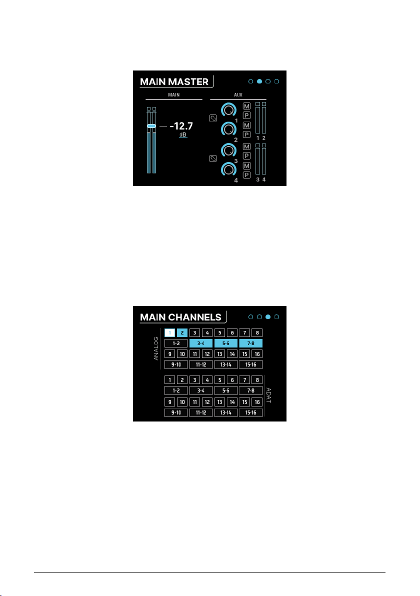
7.3.2. MAIN MASTER
Scroll past the last Main Mixer channel selector to access the second page of settings — the
MAIN MASTER page.
This page shows the Main Master fader on the left, and the Master Aux controls on the right.
Each Aux has its own level and mute controls, plus a switch to set the Aux to be pre-fader.
Aux 1 & 2 and/or Aux 3 & 4 can be linked to become a stereo Aux if desired, using the two
Stereo Link buttons on this screen.
7.3.3. MAIN CHANNELS
The last two pages of the MIXER menu are the MAIN CHANNELS pages. Here, you can scroll
through and select/deselect any channel(s) you wish to have in the Main mix.
As you can see, each channel is available to select on its own, or you can select a stereo
pair of channels instead.
• The first of these two pages is where you select from u p to 16 Analog and/or 16
ADAT channels.
• The second page is where you select from up to 32 USB "return" channels. These
are channels that come from your computer (for example your DAW's various
outputs).
Arturia - User Manual AudioFuse 16Rig - Menus and Functions 37
Page 44
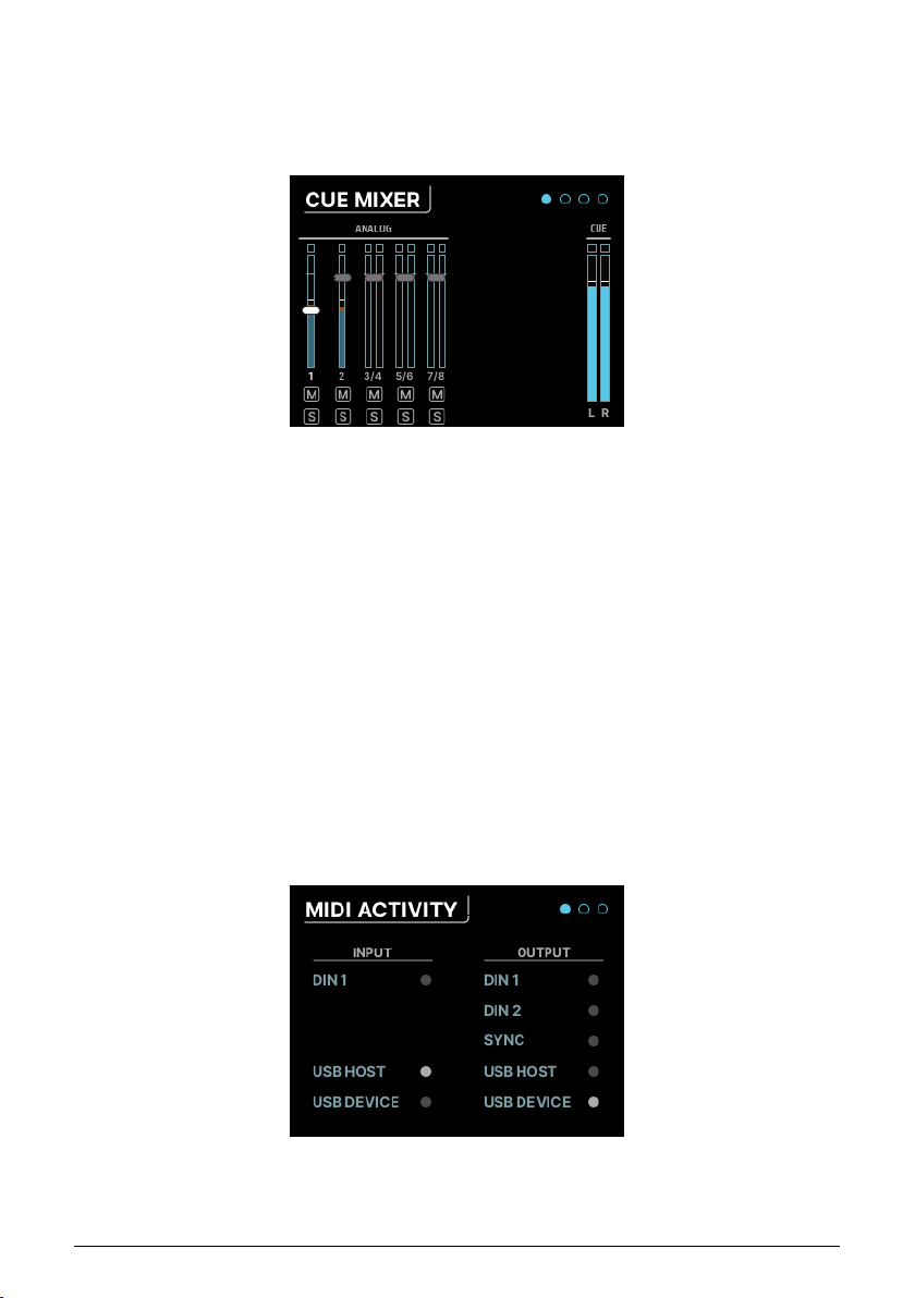
7.4. CUE
Clicking on the CUE icon takes you to the CUE MIXER pages. The Cue mix is a separate mixer
that is often used to give performers a custom headphone mix, perhaps isolating certain
elements of the Main mix to be turned up while tracking.
However, it's not just for headphones – you can use this mixer just like any other mixer. For
example, if you're working with lots of modules or synthesizers, you can create a stereo
submix and then route that mix out of the analog or ADAT outputs for further processing.
The controls and functions of the Cue mix are identical to those of the Main mix, with the
following exceptions:
1. There are no Aux buses.
2. The Cue mix is not always active. It must be switched on in order to work; this is
done either by clicking the CUE button in the Cue Mix tab of the AFCC software or
by double-clicking the front panel CUE button, which lights up red while the Cue
mix is active. Double-click again to turn it off.
7.5. MIDI
Clicking on the MIDI icon in the carousel accesses the MIDI menu, which has 3 pages:
7.5.1. MIDI ACTIVITY
38 Arturia - User Manual AudioFuse 16Rig - Menus and Functions
Page 45
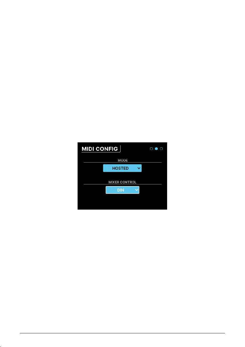
This page has a set of MIDI activity indicators, that light up when MIDI signals are received
from the appropriate inputs or sent to the corresponding outputs.
INPUT sources include:
• DIN1: the rear panel 5-pin DIN MIDI IN
• USB HOST: the front panel USB port labeled MIDI
• USB DEVICE: MIDI messages coming from your music software and/or
computer (via USB)
OUTPUT sources include:
• DIN1 and DIN2: the two rear panel 5-pin DIN MIDI OUT/THRU
• SYNC: the rear panel CLOCK OUT minijack
• USB HOST: the front panel USB port labeled MIDI
• USB DEVICE: MIDI messages going to your music software and/or computer (via
USB)
7.5.2. MIDI CONFIG
The MODE control is a drop-down menu that lets you set how the AudioFuse 16Rig responds
to MIDI.
• STANDALONE: The AudioFuse 16Rig passes MIDI from sources to destinations
without the need for a computer. These routings are set in the STANDALONE MIDI
page described below.
• HOSTED: The interface connects the attached MIDI gear to a host computer. The
music software on the host computer can then decide where the MIDI signals
are routed.
AudioFuse 16Rig's Main mixer is MIDI controllable. The MIXER CONTROL drop-down
determines which MIDI inputs port will provide MIDI control messages to the AudioFuse
16Rig's mixer. This lets you quickly manipulate mixes using a control surface rather than
using the front panel controls or the AFCC software.
Choices include: NONE, DIN, USB HOST, USB DEVICE
Arturia - User Manual AudioFuse 16Rig - Menus and Functions 39
Page 46
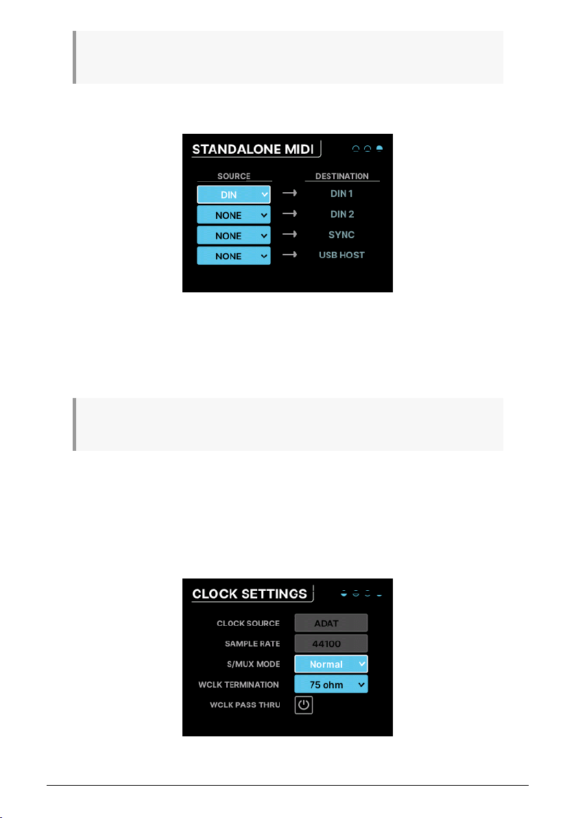
If you're sure you don't want to use MIDI to control the mixer, set MIXER CONTROL to NONE to avoid
accidentally changing mixer settings with your connected MIDI devices.
7.5.3. STANDALONE MIDI
When in standalone mode, the AudioFuse 16Rig needs to know how to route MIDI signals
between its various ports. This menu lets you set that up.
There are four fixed destinations: DIN1, DIN2, SYNC, USB HOST.
Each can be connected to one of the following sources: NONE, DIN, USB HOST, USB+DIN
What happens if you send two or more sources to one destination? The AudioFuse 16Rig will
their MIDI signals, acting like a sort of MIDI mixer.
merge
7.6. SETTINGS
Clicking on the SETTINGS icon accesses four pages of system settings and information
displays.
7.6.1. CLOCK SETTINGS
40 Arturia - User Manual AudioFuse 16Rig - Menus and Functions
Page 47

When connecting multiple digital hardware devices in the same rig, solid
clock sync
is vital.
If two devices' clocks don't line up and run in sync, audio artifacts will be introduced in
the form of clicks, pops and various kinds of noise (known as
jitter
). That's why AudioFuse
16Rig is equally capable of providing tight clocking to other devices, or following the clock
generated by another device.
AudioFuse 16Rig can operate on its own internal clock, or use an input clock signal from the
ADAT inputs or the Word Clock input. The clock source and sample rate are displayed at the
bottom of most screens (and shown here on the CLOCK SETTINGS page), and they can be
set on the interface itself or using the AudioFuse Control Center [p.8] software.
Parameters on this page include:
• Clock Source: This can be set to Internal (INT) Clock, ADAT Clock, or WORD Clock.
It defaults to INT and cannot be changed if no other digital device is connected
to the interface.
• Sample Rate: This can be set to 44100, 48000, 88200, 96000, 176400, or
192000 Hz. If the Clock Source is set to INT and the AudioFuse 16Rig is
connected to a host computer, then the sample rate will be set by the host and
cannot be changed within the interface itself.
◦ Sample rates above 48000 Hz will be available with limited
capabilities.
▪ At 88200 or 96000 Hz, the interface offers 16 analog
inputs, 12 analog outputs, and 8 ADAT inputs and outputs.
▪ At 176400 or 192000 Hz, the interface offers 8 analog
inputs and 10 analog outputs, with no digital inputs or
outputs.
• S/MUX Mode: When set to Normal, the interface automatically detects the
incoming ADAT clock and sets its sampling rate accordingly. This is the default
and should work well in most cases. However, if you select Force, the interface
will interpret incoming data as 88.2/96 kHz even if it "sees" 44.1/48 kHz. This is
necessary because some devices' ADAT outputs don't have the right metadata
embedded in their signals, so the sample rate can be misinterpreted. The Force
function prevents this.
• Word Clock Termination: The BNC cables that transmit word clock data are very
sensitive to changes in impedance. Usually when a connection terminates, it
wants to see a 75 ohm impedance. Under some circumstances, though, a very
high impedance is needed. This control lets you choose either 75 ohm or Hi-Z
termination.
• Word Clock Pass Thru: If your AudioFuse 16Rig is part of a larger word clock
network and is synchronized to an external clock, it can pass word clock data
through the interface to another device in a daisy chain.
Arturia - User Manual AudioFuse 16Rig - Menus and Functions 41
Page 48
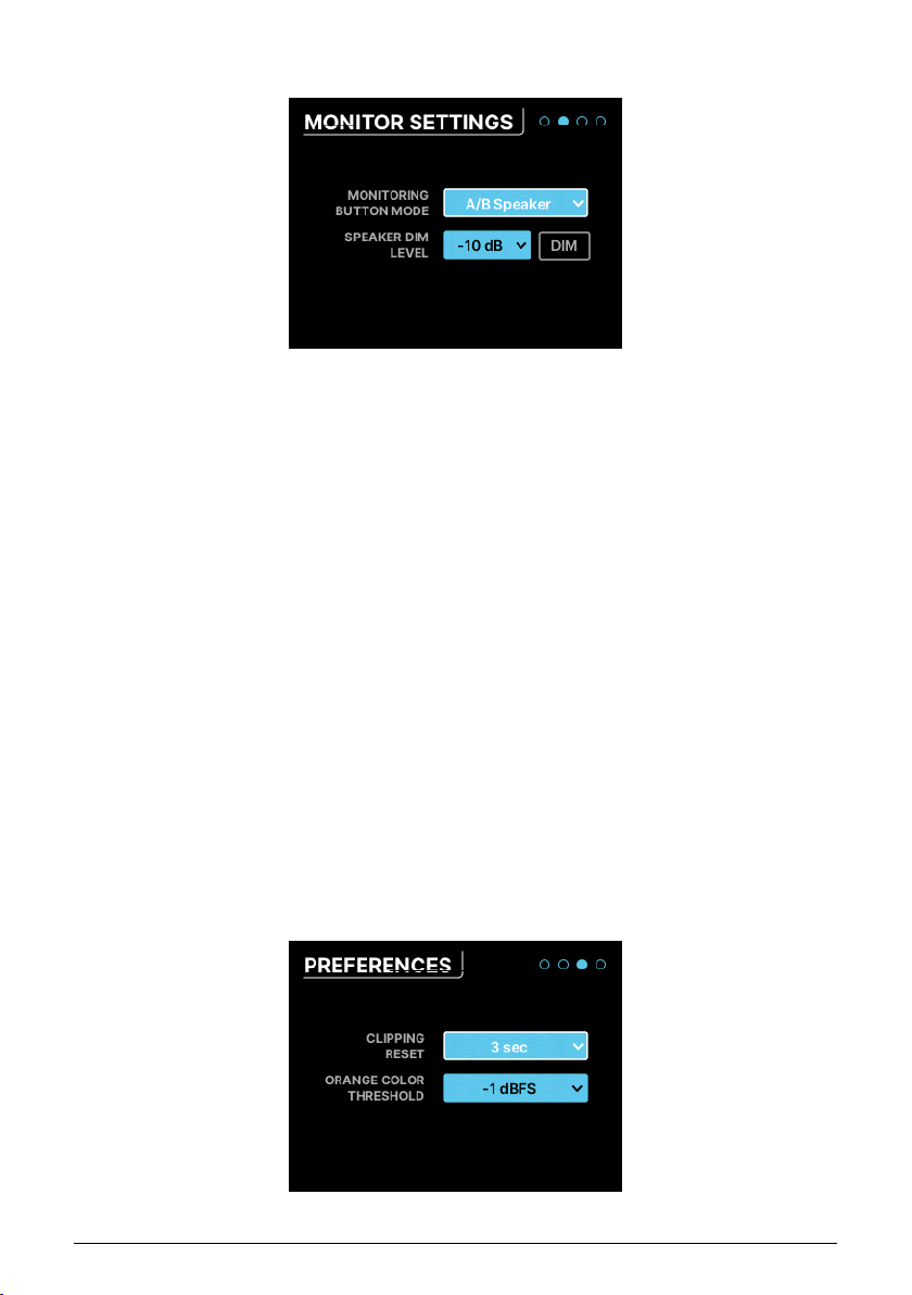
7.6.2. MONITOR SETTINGS
This page contains several speaker-related settings:
• Monitoring Button Mode: This dropdown menu selects what the Monitoring button
on the front panel does. The chosen function causes the button to light up in a
particular color, so you can tell at a glance what it does. The button will blink
when activated. Settings include:
◦ Mono (green): sums the signals of Left and Right outputs and sends
them to both speakers. This is useful when checking mono
compatibility or when checking for phase-related issues.
◦ Dim (orange): turns down the speaker output by a designated amount
(see below). This lets you take a moment to chat with someone else
in the studio with the sound lowered, then return it to its previous level
precisely.
◦ A/B Speaker (blue): mutes the main Speaker outputs and switches on
a pair of outputs designated by the user – any analog output pair on
the rear panel can be designated as the B Speakers, and trim controls
assure that levels match the A Speakers (i.e. the Monitor outputs). Note
that this button does not do anything if the A/B function isn't activated.
• Speaker Dim Level: This drop-down sets the amount by which the Dim button
lowers the speaker level. You can choose either –10dB or –20dB.
• DIM button: Engages and disengages dimming without leaving this page. It's a
handy way to test which amount of dimming you prefer.
7.6.3. PREFERENCES
42 Arturia - User Manual AudioFuse 16Rig - Menus and Functions
Page 49
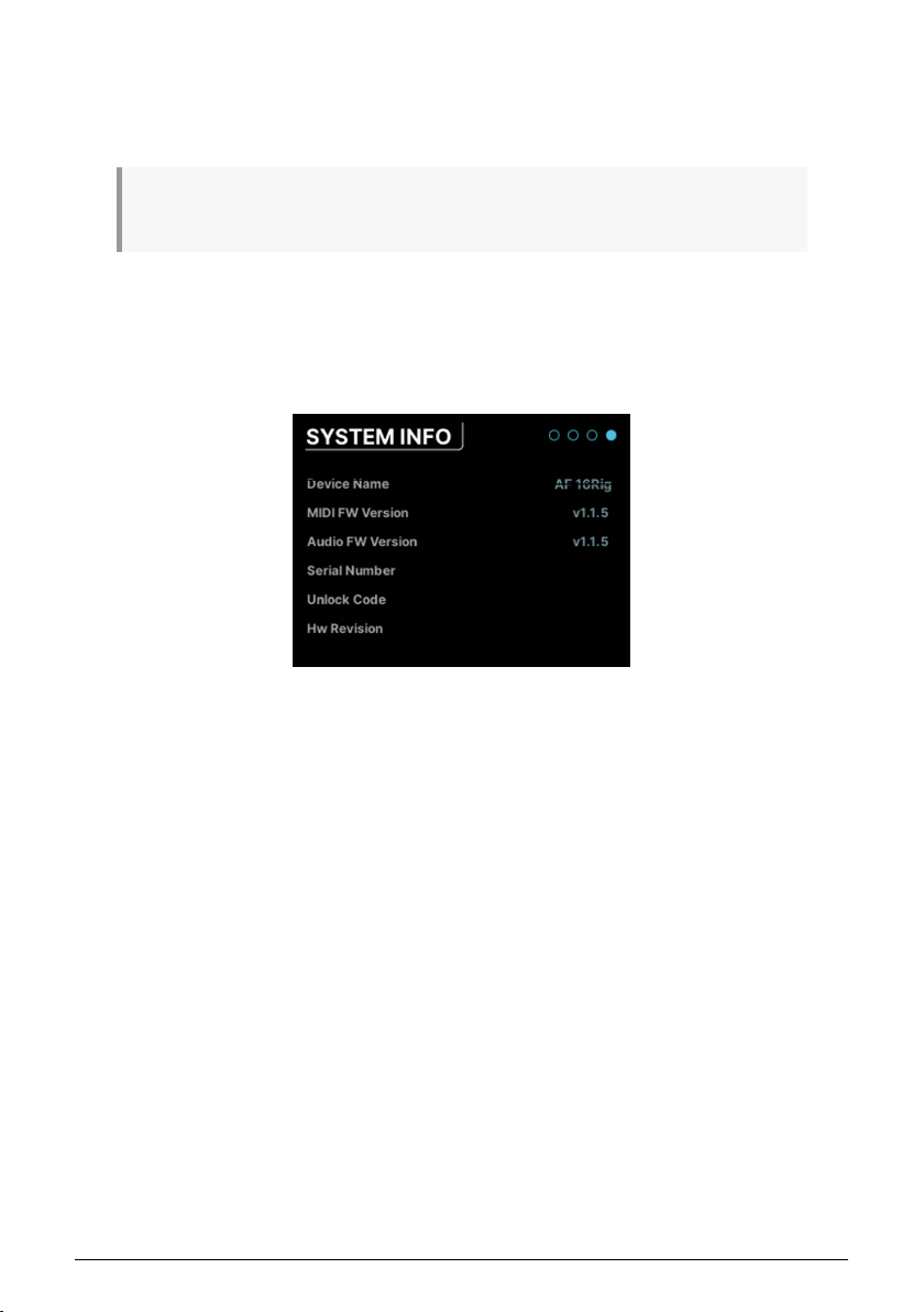
Here you can configure AudioFuse 16Rig to suit your preferences.
Clipping Reset: This drop down sets the amount of time it takes for clipping indicators to
automatically clear. This is a global setting that affects all meters in the hardware and also
AFCC. Options include 1.5 seconds, 3 seconds, or Infinite.
Note: If you set the Clipping Reset time to “Infinite” the clip indicators will not clear automatically. In
this case you will need to clear the meters manually by clicking and holding the encoder for 3 seconds.
Orange Color Threshold: This drop down sets the point at which the VU meter color changes
from green to orange. This is a global setting that affects all meters in both the hardware
and also in AFCC.
7.6.4. SYSTEM INFO
This "About" screen lists some of your interface's operational details, such as:
• MIDI Firmware Version
• Audio Firmware Version
• Serial Number
• Hardware Revision
7.7. PRESETS
One of the fun things you can do with the AudioFuse 16Rig is to use it in standalone mode,
with no computer attached to it. It's a very handy mixer with lots of routing flexibility, and it
doesn't need a host program to be useful in that regard.
However, it does require a place to save all of its routing and mix settings when the computer is not connected. That's one of the many uses for Presets.
Presets can also be very useful even when the AudioFuse 16Rig isn't in standalone mode; if
you have different workflows for recording music, doing voiceovers, reamping instruments,
and so forth, you can speed up your work by saving each configuration as a Preset.
Arturia - User Manual AudioFuse 16Rig - Menus and Functions 43
Page 50
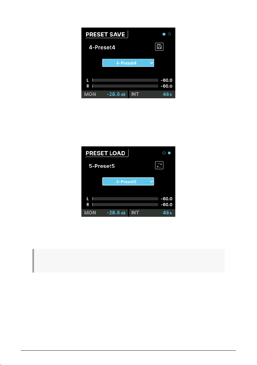
7.7.1. PRESET SAVE
This page has a Save button and a drop-down menu for choosing which of the eight
available preset slots you want to save to. The current preset is displayed at top left; if there
is a star after the name, it means the preset has been altered from the saved version.
7.7.2. PRESET LOAD
This page is identical to the PRESET SAVE page, but has a Load button instead. Notice that
the Load preset actually has nine presets. This is because there is a preset called "0-Factory"
that loads AudioFuse 16Rig's factory defaults and can not be overwritten.
Note that Presets can be renamed in AFCC, so they're easier to differentiate than "Preset-1" or
"Preset-8".
44 Arturia - User Manual AudioFuse 16Rig - Menus and Functions
Page 51
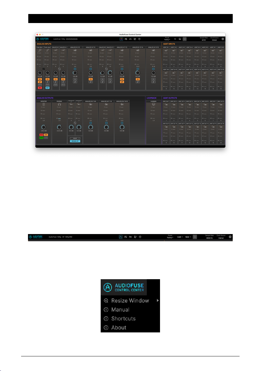
8. AUDIOFUSE CONTROL CENTER
While nearly all of the AudioFuse 16Rig's functions can be accessed from the front panel
controls, you may find it more convenient to control your interface from a computer. Like all
AudioFuse interfaces, the AudioFuse 16Rig can be set up and controlled from the AudioFuse
Control Center (AFCC) software.
AFCC makes everything easier, from monitoring levels to configuring channels to setting
up MIDI controls and mixing. It can control multiple AudioFuse interfaces connected to the
same computer; in this chapter, we'll cover its functions and layout for the AudioFuse 16Rig.
8.1. The Upper ToolBar
The Upper Toolbar gives you quick access to general controls for AFCC.
8.1.1. AFCC Menu
Arturia - User Manual AudioFuse 16Rig - AudioFuse Control Center 45
Page 52
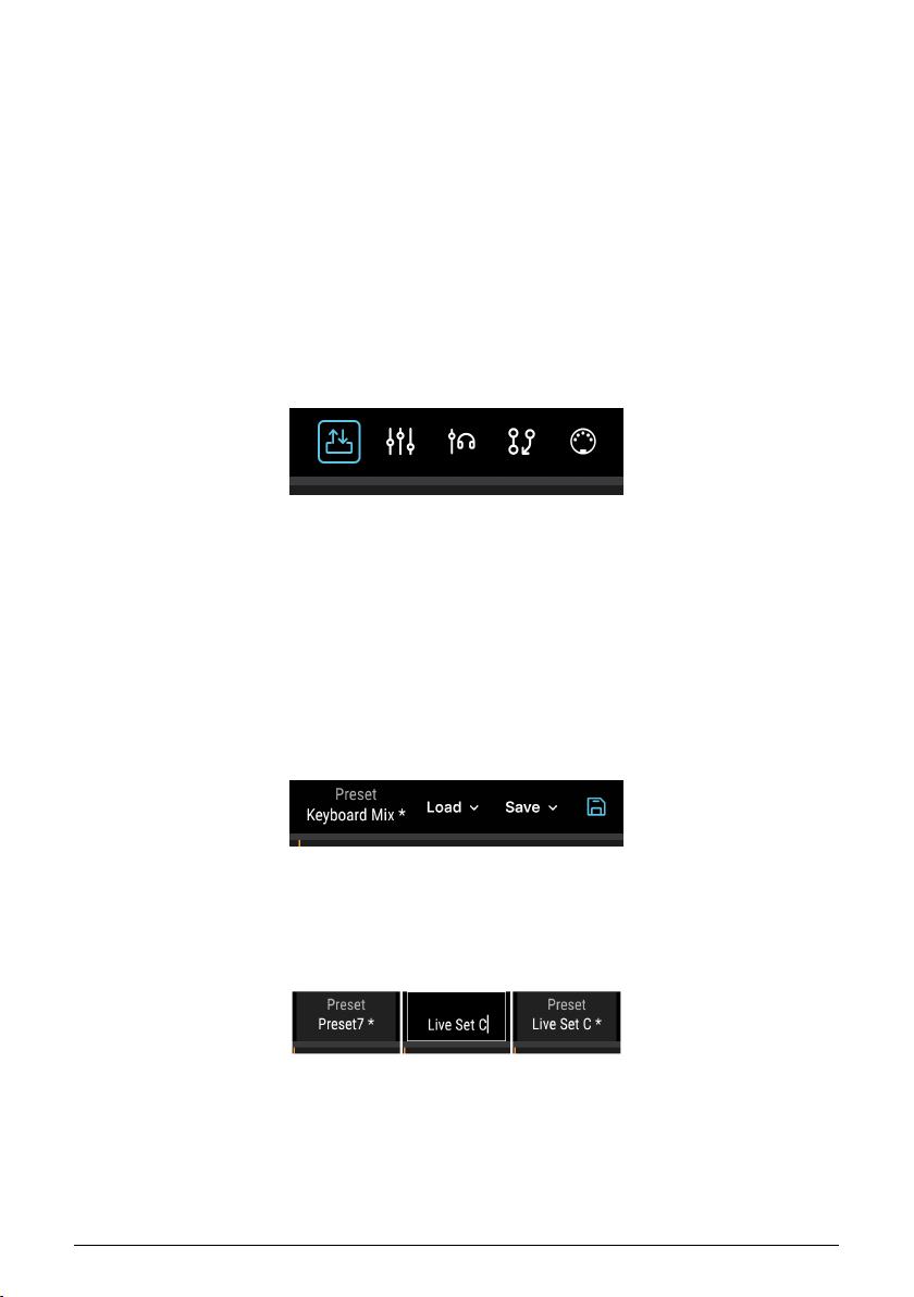
At the far left of the Upper Toolbar is the AFCC Menu. Click on the logo to get a drop-down
menu with the following three choices:
• Resize Window: Lets you choose an optimal interface size for your computer's
display.
• Manual: opens this manual.
• Shortcuts: Opens a window with all AFCC and AudioFuse 16Rig shortcuts
conveniently located in one place. Memorizing these will really help you speed
up your workflow in the longrun.
• About: opens a window with the current software version and a list of credits.
(Now you know whom to thank for this cool program!)
Next to the AFCC Menu logo is the type of interface connected (in this case, "AudioFuse
16Rig") and the name of your interface, which you can set in the Settings menu [p.42].
8.1.2. Screen Selectors
The five Screen Selectors in the center of the Upper Toolbar let you select the desired screen (view) of the plug-in interface. We will cover these in detail below; they are:
• Overview
• Mixer
• Cue
• Routing
• MIDI
8.1.3. Preset Controls
Next are the Preset Controls. These include the following functions:
8.1.3.1. Preset Name (and Rename)
To rename a preset (left), click inside the
field and retype (center), then press Enter
or click outside the field to save the name
46 Arturia - User Manual AudioFuse 16Rig - AudioFuse Control Center
(right).
Page 53
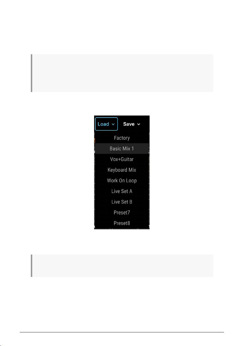
The name of the currently loaded preset is displayed first. If there's a star (*) after the name,
it indicates that the current settings in AFCC don't match what's saved in the preset – in other
words, there are unsaved edits. These will be lost if you don't save the preset before loading
another one.
Click on the preset name to change it to something you'll quickly recognize, like "Synth Mix"
or "Voiceover". Preset names can be up to 12 characters long.
NOTE: Renaming a preset and saving an edited preset are two separate operations – you can save
a preset without renaming it, and you can rename a preset without saving any edits you've made (if
any). In the left image above, the star in "Preset7 *" indicates that the original Preset7 has been edited.
Even with the new name saved, the star is still there to show that the preset itself has unsaved edits.
These will be lost if you load a different preset before saving this one.
8.1.3.2. Preset Load
The Load icon reveals a drop-down menu of the eight presets plus the Factory preset, a
default you can always use if you want to start with a clean slate.
The Factory preset can't be edited and saved, or overwritten. If you start with the Factory preset and
edit it to fit your needs, you must save the result into one of the eight preset slots.
Arturia - User Manual AudioFuse 16Rig - AudioFuse Control Center 47
Page 54
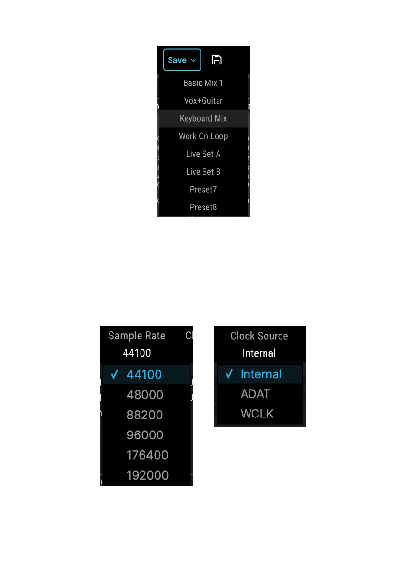
8.1.3.3. Preset Save and Quick Save
Note the Quick Save
diskette icon next to the
Save button.
The Save icon opens a drop-down menu indicating where an edited preset may be saved.
Next to it is the floppy-diskette Quick Save icon, which you click to save an edited preset into
the same slot.
8.1.4. Sample Rate and Clock Source
48 Arturia - User Manual AudioFuse 16Rig - AudioFuse Control Center
Page 55
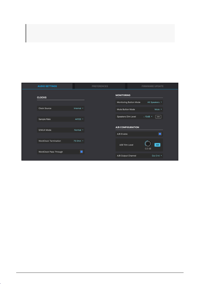
These drop-down menus let you select the Sample Rate, from 44.1 to 192 kHz, and Clock
Source, whether Internal, ADAT, or Word Clock.
NOTE: Selecting a sample rate higher than 48 kHz will limit the capabilities of the AudioFuse 16Rig.
See the section on Clock Settings [p.40] for more information.
8.2. Global Settings
The last icon in the Upper Toolbar, the gear, opens a pop-up Settings menu with three tabs.
8.2.1. Audio Settings
These settings cover clocking, monitoring, and configuration of the A/B Speakers. They
include:
• Clock Source
• Sample Rate
• Force S/MUX
• WordClock Termination
• WordClock Pass Through
• Monitoring Button Mode
• Speakers Dim Level and DIM button
• A/B Enable
• A/B Trim Level
• A/B Output Channel
These features are identical to, and offer the same options as, their corresponding hardware
settings as described in the hardware CLOCK SETTINGS [p.40] and MONITOR SETTINGS
[p.42] pages under the SETTINGS menu, as well as the A/B CONF settings in the MONITOR
[p.34] menu.
Arturia - User Manual AudioFuse 16Rig - AudioFuse Control Center 49
Page 56
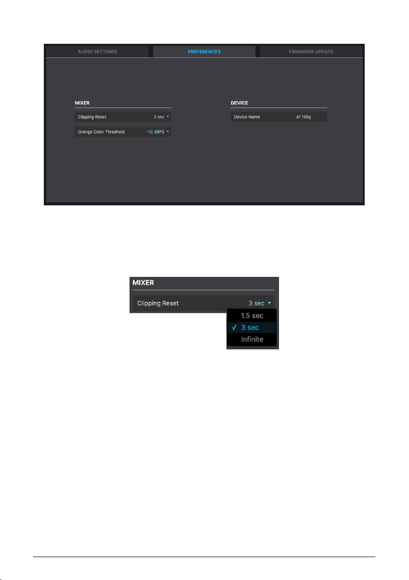
8.2.2. Preferences
You can adjust these settings to your personal preference. These settings affect both AFCC
and the AudioFuse 16Rig hardware.
8.2.2.1. Clipping Reset
This controls how long a level meter will indicate clipping before it resets itself. Options
include 1.5 seconds, 3 seconds, and Infinite (clip indicators remain lit until manually reset,
as explained here [p.18]).
50 Arturia - User Manual AudioFuse 16Rig - AudioFuse Control Center
Page 57
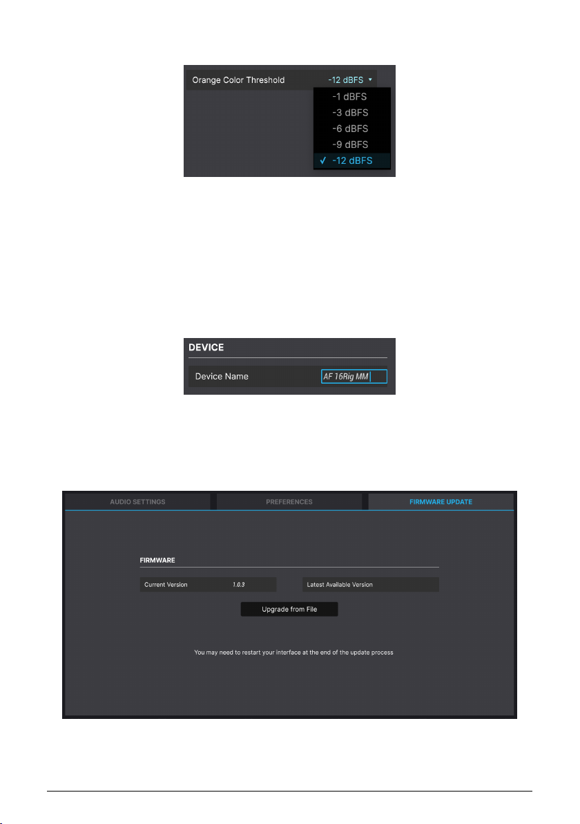
8.2.2.2. Orange Color Threshold
The AudioFuse 16Rig's meters show green for lower-level signals and red for clipping. In
between, there's a level range indicated in orange. Some users like a lot of warning before
they get close to clipping, while others want less.
This drop-down menu lets you choose the level at which the meter displays turn orange,
from a very conservative –12 dBFS to a riding-the-edge -1 dBFS. Note that your selection here
is represented in both AFCC and the hardware.
8.2.2.3. Device Name
You can name your AudioFuse 16Rig. This name will be displayed in the Upper Toolbar, and
is useful you have more than one AudioFuse interface connected to your computer.
8.2.3. Firmware Update
Sometimes Arturia will release new firmware for AudioFuse 16Rig, whether to fix bugs or
add new features. Use this tab to check your current firmware version vs. what's available
online at Arturia's website, download the latest firmware, and install it.
Arturia - User Manual AudioFuse 16Rig - AudioFuse Control Center 51
Page 58
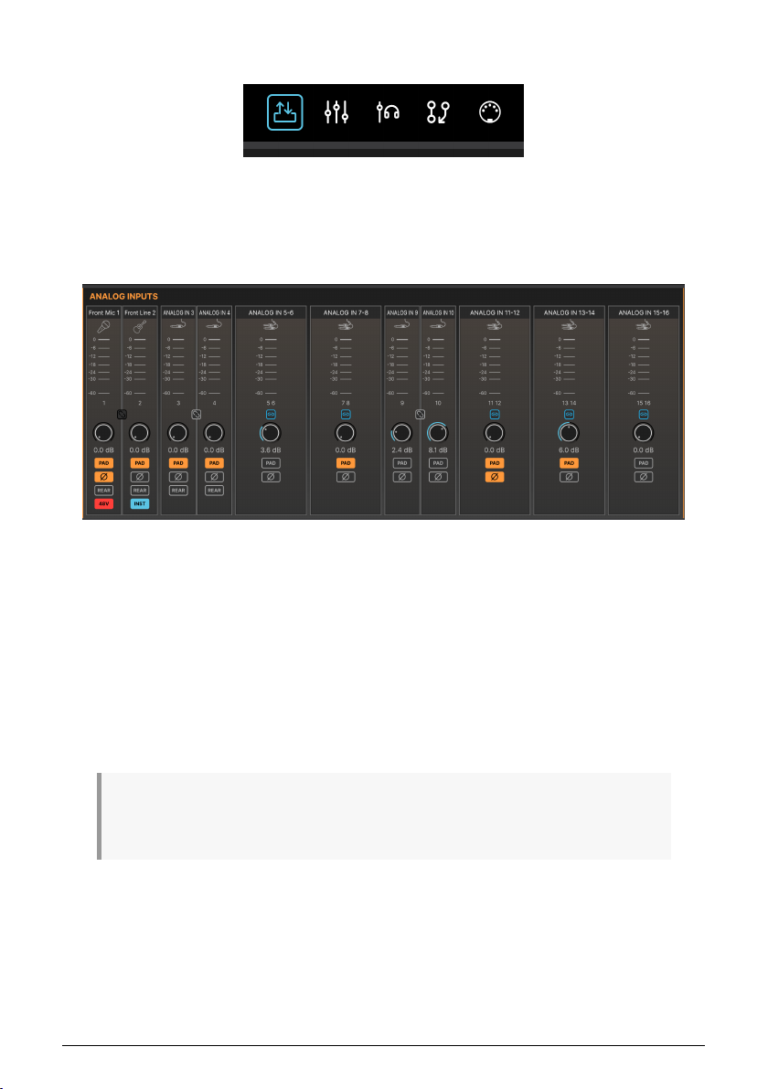
8.3. Overview Screen
Clicking the first of the Screen Selector icons opens an overview of the AudioFuse 16Rig's
inputs and outputs, with level meters and various controls.
8.3.1. Analog Inputs
The upper left section of the Overview screen contains meters and controls for the Analog
Inputs. These duplicate the features of the hardware, but allow for all inputs to be seen at
once. Each in put has a level meter, stereo Link button shared with the adjacent input, gain
control, and buttons for Pad and Phase.
In addition, the first four inputs can be switched to the Rear jacks on the hardware. This
lets you leave cables plugged into the Input 1 and 2 XLR/TRS jacks and the Input 3 and 4
minijack while sending other signals to their corresponding rear-panel inputs. Remember, if
the Rear button is not pressed, the corresponding rear inputs will be ignored.
Inputs 1 and 2 will also display a 48V button for phantom power if an XLR cable is plugged
into the front panel, or an INST button for high-impedance instrument-level signals if a 1/4"
cable is plugged into the front panel.
Note that some of these function buttons (48V and INST, for example) will only appear if appropriate
front-panel connections are made. If the appropriate cable is not connected to the front panel, the
button(s) will not be shown.
52 Arturia - User Manual AudioFuse 16Rig - AudioFuse Control Center
Page 59
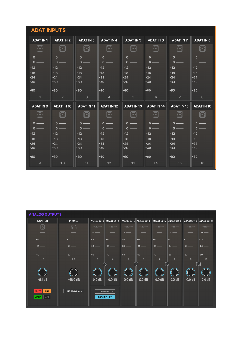
8.3.2. ADAT Inputs
The upper right portion of the Overview screen has 16 level meters for the ADAT digital
inputs. There are no controls associated with these meters.
8.3.3. Analog Outputs
Arturia - User Manual AudioFuse 16Rig - AudioFuse Control Center 53
Page 60
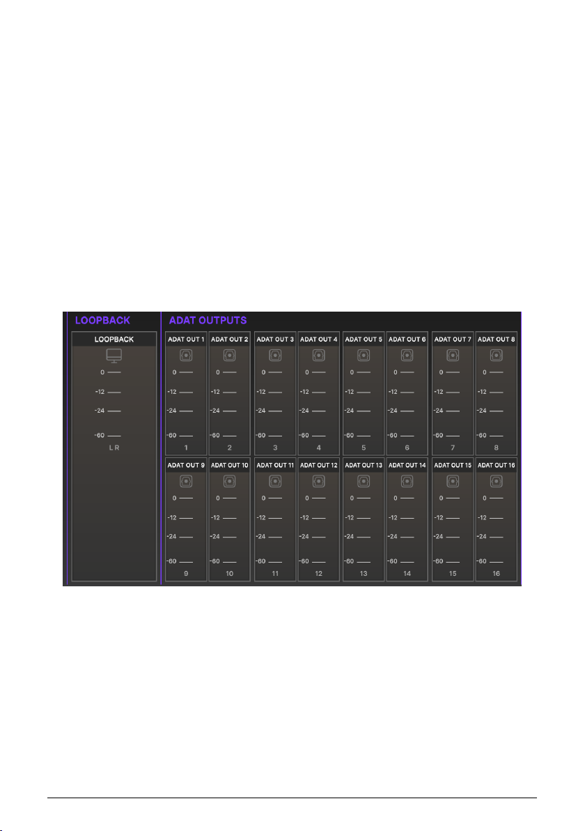
The lower left portion of the Overview screen has controls and level meters for all of the
Analog Outputs. Each output channel has metering, a stereo Link button to connect adjacent
mono channels, and an output level control.
In addition, the MONITOR output pair has controls for MUTE, DIM, MONO, and A/B functions,
corresponding to those on the hardware. If A/B Speaker capability is not enabled, the A/B
button is greyed out.
The PHONES section has an indicator showing the position of the Phones knob on the
front panel. Note that this on-screen control is for display purposes only. To change the
level, use the physical knob on the front panel. This section also has a drop down menu
letting you adjust the output level of the headphone amp to better match the impedance
of your headphones, letting you easily use both low and high impedance headphones with
AudioFuse 16Rig.
Analog Outputs 3 and 4 on the front panel have a drop-down menu for selecting their
function: LINE, REAMP, DIRECT THRU, and ALT PHONES. In addition, a GROUND LIFT switch
is available to eliminate possible ground loop hum when connecting the AudioFuse 16Rig
outputs to guitar amps and other gear.
8.3.4. Loopback and ADAT Outputs
The lower right portion of the Overview screen provides output level metering for the stereo
Loopback signal and for all 16 ADAT digital outputs.
54 Arturia - User Manual AudioFuse 16Rig - AudioFuse Control Center
Page 61
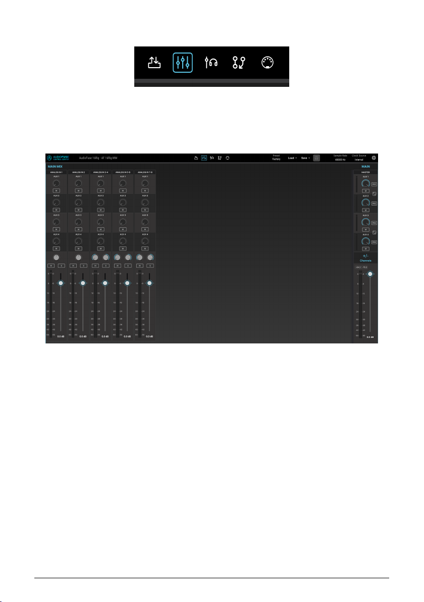
8.4. Main Mixer Screen
This screen brings u p AudioFuse 16Rig's Main mixer, and provides functions that let you build
and set it far more quickly and easily than with the user interface of the AudioFuse 16Rig
itself.
When you open this screen for the first time, it will look like this:
The Factory preset populates the Main mixer with a set of eight analog input channels as
shown here.
The controls for the MAIN section are present on the right. They include:
• AUX 1–4: These are controls for the four Aux buses. Each has a level meter at left,
level control, and M (Mute) and PRE (Pre-fader) buttons. In addition, Aux 1 and 2
can be linked to form one stereo bus, and Aux 3 and 4 can do the same.
• +/– Channels: Click here to add channels to the mix, as described below.
• The Master output level meters and fader are here. Numerical displays above the
meters show the highest level seen so far, in dBFS.
8.4.1. Adding Channels
If the starting configuration isn't precisely what you need, the Main mixer screen allows you
to build a custom mix, adding the inputs you need and leaving out the ones you don't. This
is done with the Main Channels pop-up window.
Arturia - User Manual AudioFuse 16Rig - AudioFuse Control Center 55
Page 62
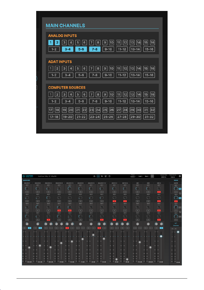
Click on the +/– Channels button to open the Main Channels window. All available inputs are
displayed, both in mono and linked stereo. Active channels are lit while inactive channels
are not. Click on an inactive channel to add it to the mixer. Click again to deselect a channel
and remove it from the mixer.
Once you've selected the channels you want, click anywhere outside the Main Channels
pop-up to dismiss it. Your populated Main mixer screen might look something like this:
56 Arturia - User Manual AudioFuse 16Rig - AudioFuse Control Center
Page 63
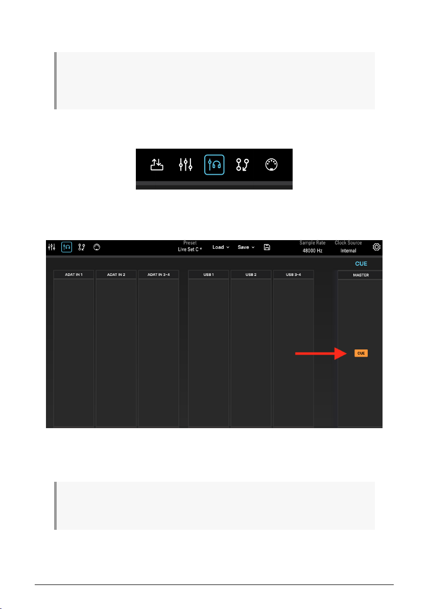
Each channel has a send level and M (Mute) button for each of the Aux buses, a Pan control,
M (Mute) and S (Solo) buttons, a level fader, and a meter with clip indicator.
Remember that the Main Mixer's output needs to be routed to a pair of analog or digital outputs for
you to hear it. If you see activity in the mixer's level meters but you cannot hear the output, check your
connections in the Routing Matrix [p.58] and make sure the output of the mixer is routed to where you
want it to go.
8.5. Cue Mixer Screen
The Cue mixer screen is identical to the Main mixer screen in features and operation, aside
from the lack of Aux buses. Clicking the +/– Channels button brings u p a Cue Channels popup window that works the same way as in the Main mixer.
There is one other important difference when it comes to the Cue Mixer. There is a CUE
button above the Master fader, which turns the Cue mix on or off. This corresponds to the
CUE button on the front panel of the AudioFuse 16Rig itself.
If you cannot hear the output of the Cue mixer, please make sure the CUE button is switched on and
the output of the Cue mixer is routed to your desired analog or digital outputs. This can be done through
the AudioFuse 16Rig's Routing matrix.
Arturia - User Manual AudioFuse 16Rig - AudioFuse Control Center 57
Page 64
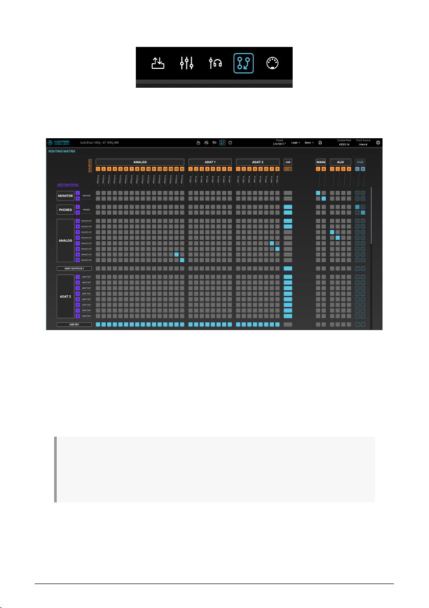
8.6. Routing Matrix Screen
With so many inputs and outputs, the AudioFuse 16Rig provides many choices for routing
signals. The Routing Matrix screen lets you make sense of the many possible routing options
and see at a glance where signals are going.
The Routing screen shows a matrix of SOURCES (columns listed from left to right and
numbered in gold) and DESTINATIONS (rows listed from top to bottom and numbered in
purple). To make a connection, simply click the point where the source and destination
intersect in the matrix. Connections are shown with blue squares.
When working in the router, you will often need to make lots of "diagonal" connections,
which can be tedious to do one-by-one (often over 8 or even 16 connections at a time). To
make life easier, we've added a click-drag function that draws a line and makes diagonal
connections quickly and easily for you.
TIP: Don't think of the sources and destinations as "inputs" and "outputs"! You can get tripped up
easily that way. After all, when you send the Main mix to the Monitor jacks, you're sending an "output" to
another "output", which can quickly become confusing as you connect more and more things. Instead,
any time you're working in the Routing Matrix, just think of things as being sources and destinations. It's
a simple trick but hopefully it keeps things clear in your mind.
58 Arturia - User Manual AudioFuse 16Rig - AudioFuse Control Center
Page 65
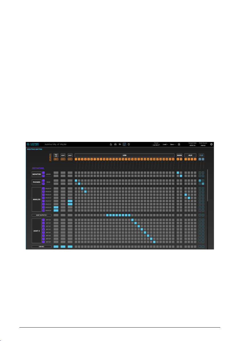
8.6.1. Sources
From left to right, the available Sources are:
• ANALOG: 16 input channels
• ADAT 1: 8 input channels
• ADAT 2: 8 input channels
• USB: 32 channels of audio playing back from your DAW
• MAIN: the stereo output of the Main mixer
• AUX: the four Aux outputs of the Main mixer
• CUE: the stereo output of the Cue mixer
Because there are so many sources, it is impossible to show them all at once on the screen.
As a result, half of the sources are minimized (or "collapsed") while the other half is being
shown, and you switch between them by clicking on the name of any minimized group of
sources.
In the screenshot above, the ANALOG, ADAT 1, and ADAT 2 sources are displayed, and the
USB sources have been collapsed into a single column. If a connection exists between
of the USB sources and a particular destination, that row will have a blue rectangle.
If you click on any of the black boxes with group labels (e.g. ANALOG or ADAT 2), the screen
will switch to the following view:
any
Here, the USB sources are displayed individually while the other three groups of sources
have been collapsed into single columns.
Arturia - User Manual AudioFuse 16Rig - AudioFuse Control Center 59
Page 66
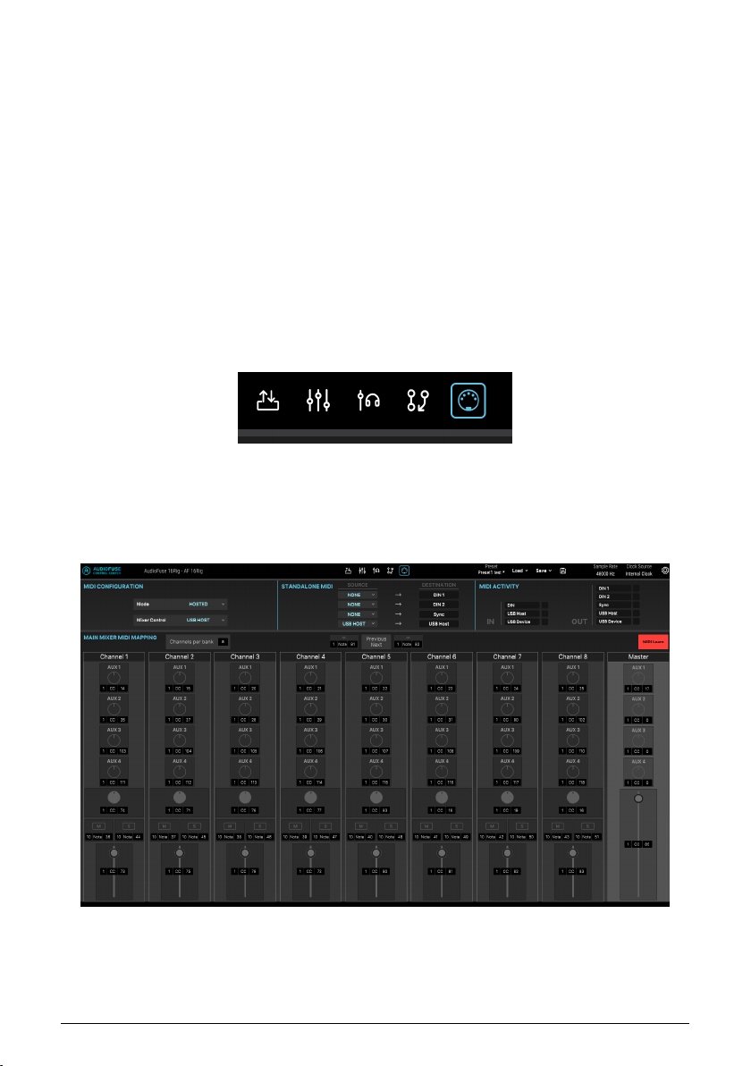
8.6.2. Destinations
In the two screenshots above, you can also see the available groups of Destinations:
• MONITOR: the rear-panel MONITOR outputs
• PHONES: the front-panel PHONES outputs
• ANALOG: the 8 LINE OUTPUTS, numbered 3 through 10
• ADAT 1: 8 channels at ADAT OUT 1
• ADAT 2: 8 channels at ADAT OUT 2
• USB: 32 channels going to your DAW to be recorded
Unlike the sources, which switch back and forth between two possible horizontal views, any
group of destinations can be collapsed into a single row or left fully expanded. If too many
rows are open for your computer screen to show them all, you can scroll through them
vertically with your mouse or scroll wheel in the usual way.
8.7. MIDI Screen
This screen allows you to monitor and configure various MIDI-related parameters. Crucially,
this includes the ability to map the various onscreen controls of the Main mixer to your MIDI
controller's physical controls (knobs, sliders, etc.) so that you can control your mix via MIDI.
You'll probably find it easier to mix with an external control surface than with your computer
mouse!
Across the top of the MIDI Screen are several important MIDI-related control sets:
60 Arturia - User Manual AudioFuse 16Rig - AudioFuse Control Center
Page 67
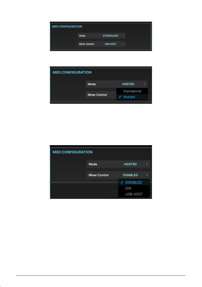
8.7.1. MIDI Configuration
The MIDI CONFIGURATION section has two controls with drop-down selection menus.
The Mode menu lets you choose whether the AudioFuse 16Rig is operating in Standalone
mode or Hosted mode.
• In Standalone mode, MIDI message routing is controlled by the AudioFuse
16Rig's Standalone MIDI [p.40] settings.
• In Hosted mode, the connected computer handles MIDI routing between in puts
and outputs.
The Mixer Control menu chooses between whether the Main mixer is controlled by MIDI
messages coming from the rear-panel DIN port, the USB HOST port, or whether MIDI mixer
control is entirely disabled. If you're not planning to control the Main mixer via MIDI, we
recommend leaving this disabled to prevent accidentally changing your mixer settings.
Arturia - User Manual AudioFuse 16Rig - AudioFuse Control Center 61
Page 68
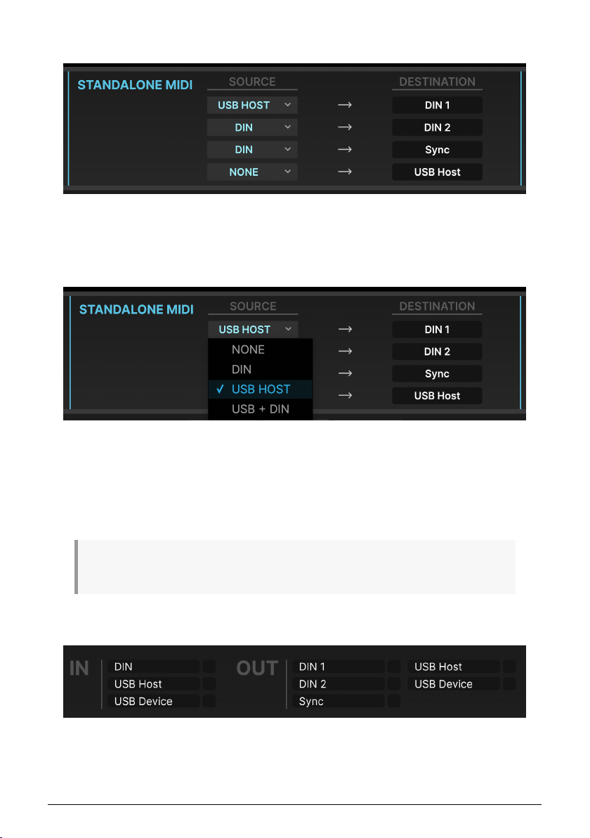
8.7.2. Standalone MIDI
The STANDALONE MIDI controls at the top center of the screen let you specify the routings
of MIDI Inputs to MIDI Outputs among the AudioFuse 16Rig's various ports when it's in
Standalone mode.
There are four fixed destinations: DIN 1, DIN 2, Sync, and USB HOST.
The following options are available for sources to route to these destinations:
• NONE
• DIN
• USB HOST
• USB + DIN (data from both ports is merged)
Note that the USB + DIN o ption is not available as a source for the Sync destination, to avoid
conflicting MIDI timing messages.
8.7.3. MIDI Activity
The top right corner of the screen has a set of MIDI ACTIVITY monitors, so you can see if
MIDI data is flowing to/from the various inputs and outputs.
62 Arturia - User Manual AudioFuse 16Rig - AudioFuse Control Center
Page 69
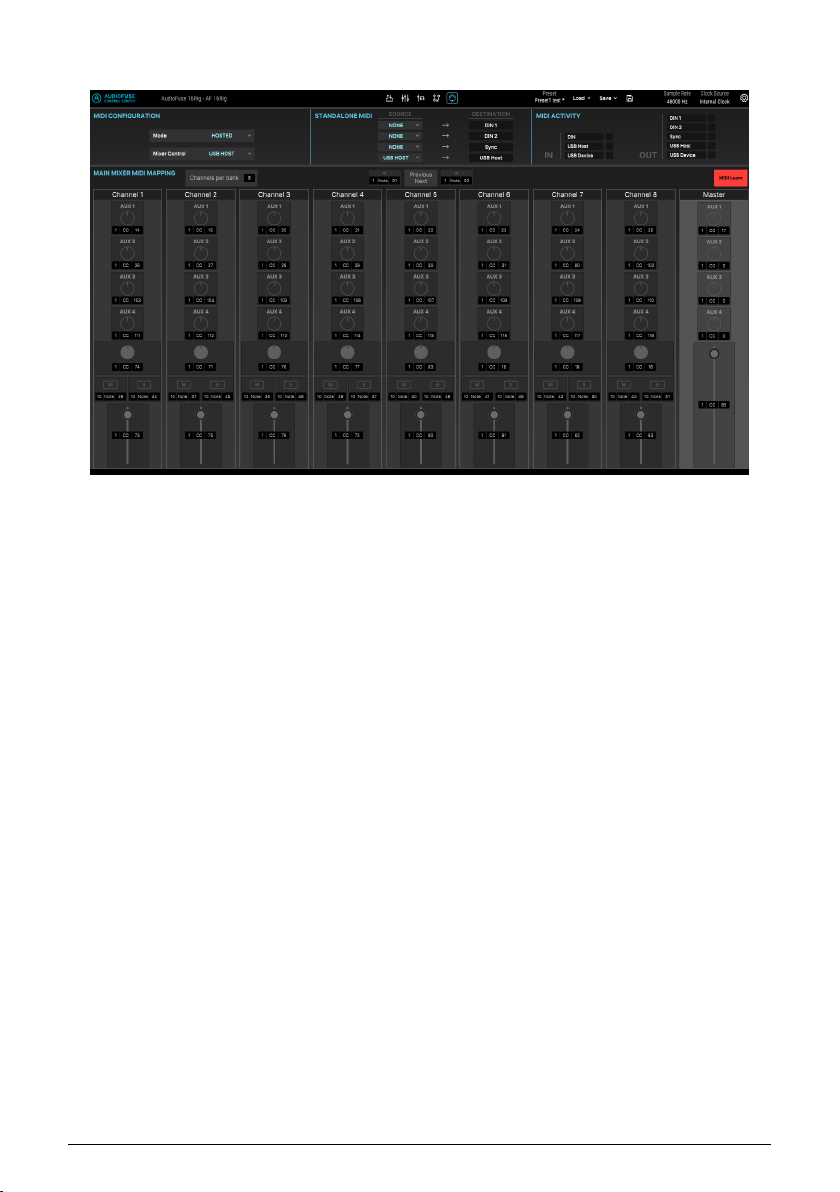
8.7.4. Main Mixer MIDI Mapping
The MAIN MIXER MIDI MAPPING screen is laid out as a "bank" of eight channels, with the following controls available for MIDI control on each channel:
• Aux 1 through Aux 4 send levels
• Channel Mute and Solo status
• Channel level
If you're working with a larger mix, the MIDI configuration works in blocks (or "banks") of
8 channels, and there are MIDI commands to let you move between blocks, jumping to the
previous or next block. The currently selected block in the Main Mixer has channel labels
that appear in blue text while all other channel labels appear in white. For example, if you
have a 24-channel mix, moving from one block to the next will give you control of channels
1 through 8, then 9 through 16, then 17 through 24. As you move from block to block, you'll
notice the channel labels change from white to blue depending on what set of controls is
under MIDI control.
In addition, the following MIDI controls are available in the Master section:
• Aux 1 through Aux 4 return levels
• Master level
Arturia - User Manual AudioFuse 16Rig - AudioFuse Control Center 63
Page 70
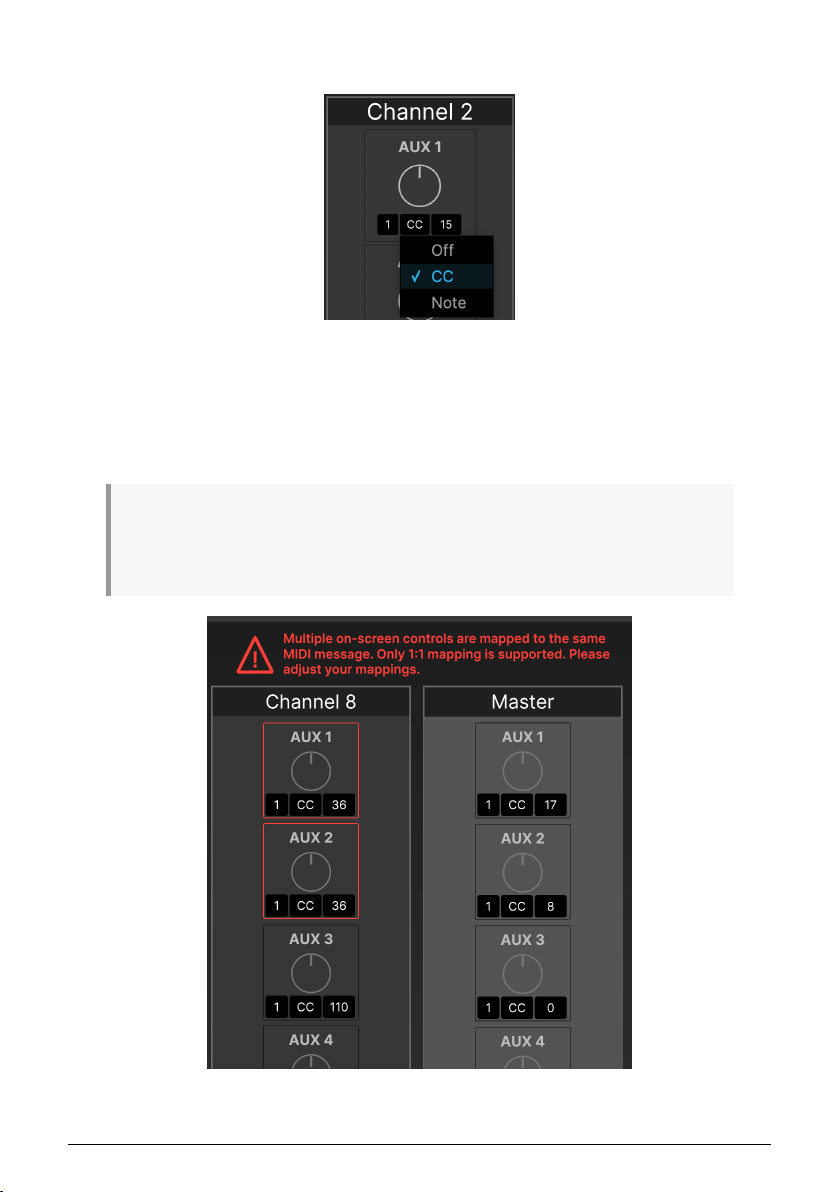
8.7.4.1. Setting MIDI control messages manually
Under each point of control, you can click on the three black boxes to set the following
parameters:
• MIDI Channel (1 to 16)
• Type of MIDI Message (Off, MIDI Control Change (CC), or MIDI Note)
• CC or Note number
Note that each on-screen control must have its own unique channel+CC/Note+value assignments
for MIDI mapping to work pro perly. If two or more controls share the same assignments, you'll get an
error message showing the controls that are in conflict, and telling you to change the values for one or
the other, as shown below:
64 Arturia - User Manual AudioFuse 16Rig - AudioFuse Control Center
Page 71
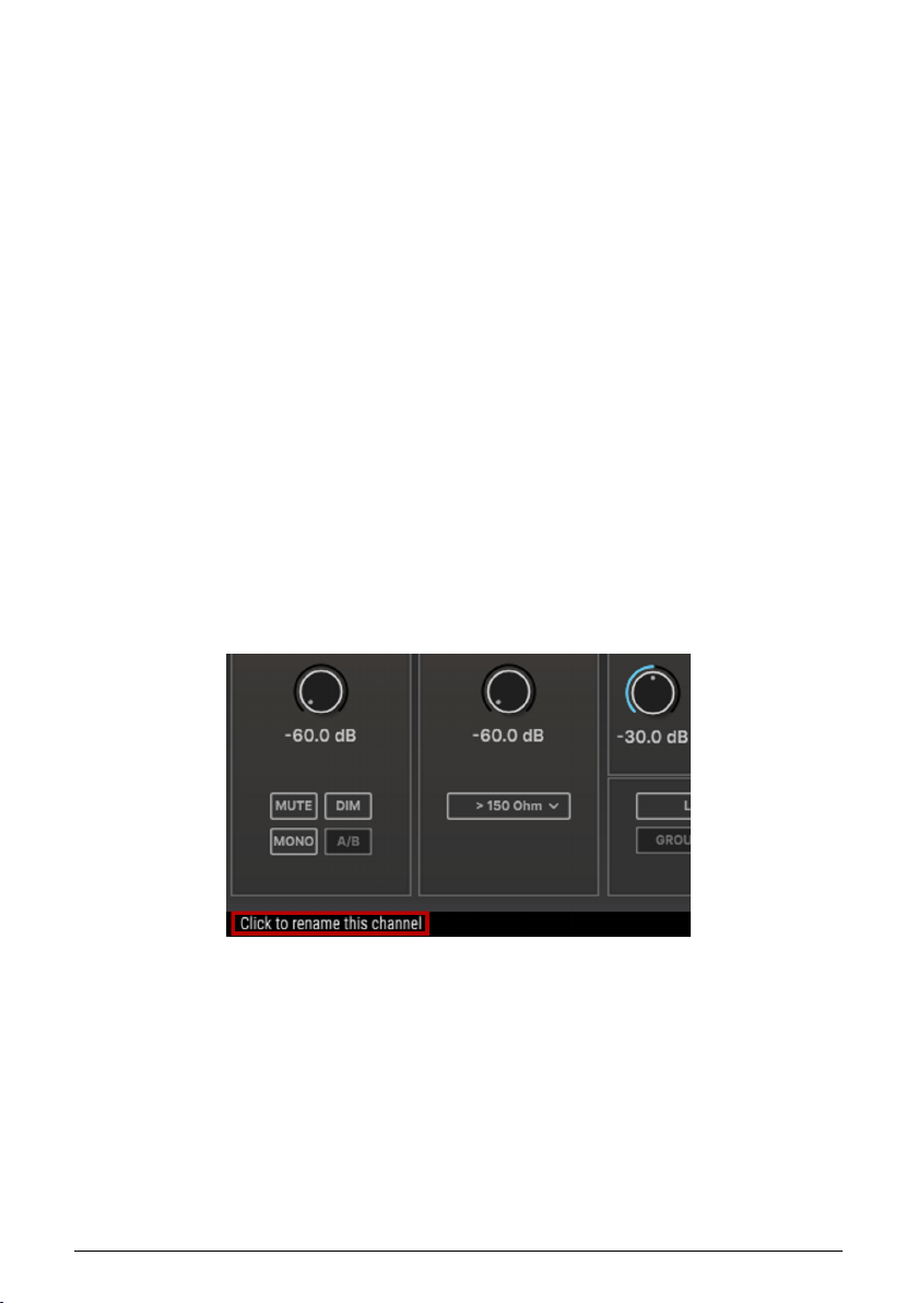
8.7.4.2. Adjusting Channels per Bank
Some desktop control surfaces have fewer than 8 channel controls (sliders, knobs, etc.)
In fact, many of the smallest controllers only have one channel’s worth of controls. To
accommodate smaller controllers, AFCC’s MIDI screen has a “Channels per bank” dropdown menu that lets you set the number of mixer channels that can be in a bank. So, for
example, if your controller only has one channel’s worth of controls, set this to 1 and you’re
all set.
8.7.4.3. MIDI Learn
To make MIDI programming easier, we’ve added a MIDI Learn function (if you don’t see
this on your screen, make sure you have updated to the latest firmware and AFCC!)
To use the MIDI Learn function:
1. Click the MIDI Learn button at the top right (it turns red when MIDI Learn mode
is engaged)
2. Click any on-screen control you’d like to re-map
3. Push, turn or move a physical control on your MIDI Controller
4. Continue steps 2-3 until you have mapped all desired controls
5. Click the MIDI Learn button again to switch off MIDI Learn mode
The Main Mixer is now re-mapped to your hardware controller.
8.8. Hover Tips
One last thing to point out, if you didn't notice it in the very first screenshot: hovering your
mouse over any control will display a detailed explanation of what the control does, shown
in the Hover Tips display at the bottom of the plug-in window. After all, everybody needs a
little extra help now and then!
Arturia - User Manual AudioFuse 16Rig - AudioFuse Control Center 65
Page 72

9. SPECIFICATIONS
9.1. System Requirements
• 4 GB RAM
• Intel i5 or later (including Apple Silicon)
• 1 GB free hard disk space
9.2. Audio Specifications
Line Inputs Measured Values
Input impedance 20kΩ (symmetric), 10kΩ (asymmetric)
Maximum input level Rear: +24dBu, Front +22dBu
Pad mode Rear: -12dB, Front: -10dB
Frequency response 20Hz to 20kHz +/-0.06dB typical
Dynamic range 118dB (A-weighted)
THD+N @ 1kHz -113dB (A-weighted)
Instrument Inputs Measured Values
Input impedance 1.1MΩ asymmetric
Maximum input level +20dBu
Gain range 55dB
Pad mode -10dB
Frequency response 20Hz to 20kHz +/-0.1dB typical
Dynamic range 114dB (A-weighted)
THD+N @ 1kHz -105dB (A-weighted)
Microphone Preamps Measured Values
Input Impedance 2,7kΩ
Maximum input level +22dBu
Gain range 55dB
Pad mode -20dB
Equivalent Input Noise (EIN) -129.5dBu (A-weighted)
Frequency response 20Hz to 20kHz +/-0.08dB
Dynamic range 117dB (A-weighted)
THD+N @ 1kHz -110dB (A-weighted)
66 Arturia - User Manual AudioFuse 16Rig - Specifications
Page 73

Speaker Outputs Measured values
Output impedance 240Ω balanced, 120Ω unbalanced
Maximum output level +20dBu
Frequency response 20Hz to 20kHz +/-0.02dB
Dynamic range 126dB (A-weighted)
THD+N @ 1kHz -114dB (A-weighted)
Line Outputs (DC coupled) Measured values
Output impedance 240Ω balanced, 120Ω unbalanced
Maximum output level +24dBu
Frequency response 20Hz to 20kHz +/- 0.04dB typical
Dynamic range 120dB (A-weighted)
THD+N @ 1kHz -106dB (A-weighted)
DC voltage amplitude +/-8.7V (asymmetrical)
Phones Outputs Measured values
Output impedance 5Ω
Maximum output level +14.4dBu
Dynamic range 109dB (A-weighted)
Power @ 33Ω @1%THD 271mW @-78dB THD
THD+N @ 1kHz -103dB (A-Weighted)
Arturia - User Manual AudioFuse 16Rig - Specifications 67
Page 74

10. APPENDICES
10.1. USB Audio mapping
AudioFuse 16Rig displays differing numbers of input and output channels in your DAW
depending on your selected sampling rate.
Sampling Rate Inputs Outputs
44.1 / 48 kHz 34 34
88.2 / 96 kHz 18 18
176.4 / 192 kHz 10 10
The tables below contain detailed information about in puts and outputs at each sampling
rate.
The given mapping is the default mapping for Factory presets. You can easily reassign and remap
everything in the AudioFuse Control Center using the Matrix [p.58].
10.1.0.1. Audio Mapping at 44.1 / 48 kHz sampling rates:
Channel Computer Input (REC) Computer Output (Playback)
1 Front/Rear In 1 Speakers/Headphones Left
2 Front/Rear In 2 Speakers/Headphones Right
3 Front/Rear In 3 Front/Rear Out 3
4 Front/Rear In 4 Front/Rear Out 4
5 Rear In 5 Rear Out 5
6 Rear In 6 Rear Out 6
7 Rear In 7 Rear Out 7
8 Rear In 8 Rear Out 8
9 Rear In 9 Rear Out 9
10 Rear In 10 Rear Out 10
11 Rear In 11 ADAT Out 1
12 Rear In 12 ADAT Out 2
13 Rear In 13 ADAT Out 3
14 Rear In 14 ADAT Out 4
15 Rear In 15 ADAT Out 5
16 Rear In 16 ADAT Out 6
68 Arturia - User Manual AudioFuse 16Rig - Appendices
Page 75

Channel Computer Input (REC) Computer Output (Playback)
17 ADAT In 1 ADAT Out 7
18 ADAT In 2 ADAT Out 8
19 ADAT In 3 ADAT Out 9
20 ADAT In 4 ADAT Out 10
21 ADAT In 5 ADAT Out 11
22 ADAT In 6 ADAT Out 12
23 ADAT In 7 ADAT Out 13
24 ADAT In 8 ADAT Out 14
25 ADAT In 9 ADAT Out 15
26 ADAT In 10 ADAT Out 16
27 ADAT In 11 USB Playback
28 ADAT In 12 USB Playback
29 ADAT In 13 USB Playback
30 ADAT In 14 USB Playback
31 ADAT In 15 USB Playback
32 ADAT In 16 USB Playback
33 Loopback In (Left) Loopback Out (Left)
34 Loopback In (Right) Loopback Out (Right)
10.1.0.2. Audio Mapping at 88.2 / 96 kHz sampling rates:
Channel Computer Input (REC) Computer Output (Playback)
1 Front/Rear In 1 Speakers/Headphones Left
2 Front/Rear In 2 Speakers/Headphones Right
3 Front/Rear In 3 Front/Rear Out 3
4 Front/Rear In 4 Front/Rear Out 4
5 Rear In 5 Rear Out 5
6 Rear In 6 Rear Out 6
7 Rear In 7 Rear Out 7
8 Rear In 8 Rear Out 8
9 Rear In 9 Rear Out 9
10 Rear In 10 Rear Out 10
Arturia - User Manual AudioFuse 16Rig - Appendices 69
Page 76

Channel Computer Input (REC) Computer Output (Playback)
11 Rear In 11 ADAT Out 1
12 Rear In 12 ADAT Out 2
13 Rear In 13 ADAT Out 3
14 Rear In 14 ADAT Out 4
15 Rear In 15 ADAT Out 5
16 Rear In 16 ADAT Out 6
17 ADAT In 1 ADAT Out 7
18 ADAT In 2 ADAT Out 8
10.1.0.3. Audio Mapping at 176.4 / 192 kHz sampling rates:
Channel Computer Input (REC) Computer Output (Playback)
1 Front/Rear In 1 Speakers/Headphones Left
2 Front/Rear In 2 Speakers/Headphones Right
3 Front/Rear In 3 Front/Rear Out 3
4 Front/Rear In 4 Front/Rear Out 4
5 Rear In 5 Rear Out 5
6 Rear In 6 Rear Out 6
7 Rear In 7 Rear Out 7
8 Rear In 8 Rear Out 8
9 Free Rear Out 9
10 Free Rear Out 10
70 Arturia - User Manual AudioFuse 16Rig - Appendices
Page 77

11. DECLARATION OF CONFORMITY
11.1. FCC
WARNING: DO NOT MODIFY THE UNIT!
Any modifications or other changes to this unit not approved by the party responsible for
compliance could void the user’s authority to operate this equipment.
This device complies with Part 15 of the FCC Rules. Operation is subject to the following
two conditions: (1) This device may not cause harmful interference, and (2) This device
must accept any interference received, including interference that may cause undesired
operation.
Responsible Party in USA: Zedra, 185 Alewife Brook Parkway, #210, Cambridge, MA 02138,
United States T: +1 857 285 5953
Trade Name: ARTURIA, Model Number: AudioFuse 16Rig
Note: This equipment has been tested and found to comply with the limits for a Class B
digital device, pursuant to part 15 of the FCC Rules. These limits are designed to provide
reasonable protection against harmful interference in a residential installation. This
equipment generates, uses, and can radiate radio frequency energy and, if not installed
and used in accordance with the instructions, may cause harmful interference to radio
communications. However, there is no guarantee that interference will not occur in a
particular installation. If this equipment does cause harmful interference to radio or
television reception, which can be determined by turning the equipment off and on, the user
is encouraged to try to correct the interference by one or more of the following measures: •
Reorient or relocate the receiving antenna. • Increase the separation between the equipment
and receiver. • Connect the equipment into an outlet on a circuit different from that to which
the receiver is connected. • Consult the dealer or an experienced radio/TV technician for
help.
11.2. CANADA
This class B digital apparatus meets complies with Canadian ICES-003.
Cet appareil numérique de la classe B est conforme à la norme NMB-003 du Canada
11.3. CE
This device has been tested and found to comply with the limits of the European Council
Directive on the approximation of the laws of the member states relating to Electromagnetic
Compatibility according to 2014/30/EU, and Low Voltage Directive 2014/35/EU.
11.4. ROHS
This device has been produced with lead free solder and fulfills the requirements of the
ROHS directive 2011/65/EU.
Arturia - User Manual AudioFuse 16Rig - Declaration of Conformity 71
Page 78

11.5. WEEE
This symbol indicates that the electrical and electronic equipment should not be disposed of
as general household waste at its end-of-life. Instead, the products should be handed over
to the applicable collection points for the recycling of electrical and electronic equipment for
proper treatment, recovery, and recycling in accordance with your national legislation and
the Directive 2012/19/EU (WEEE – Directive on Waste Electrical and Electronic Equipment).
For more information about collection points and recycling of these products, please contact
your local municipal office, your household waste disposal service, or the shop where you
purchased the product.
72 Arturia - User Manual AudioFuse 16Rig - Declaration of Conformity
Page 79

12. SOFTWARE LICENSE AGREEMENT
In consideration of payment of the Licensee fee, which is a portion of the price you paid,
Arturia, as Licensor, grants to you (referred to as 'Licensee' from now on) a non-exclusive
right to use this copy of the AudioFuse Control Center (referred to as 'SOFTWARE' from now
on).
All intellectual property rights in the software belong to Arturia SA (referred to as 'Arturia'
from now on). Arturia permits you to only copy, download, install and use the software in
accordance with the terms and conditions of this Agreement.
The product contains product activation for protection against unlawful copying. The OEM
software can be used only following registration. Internet access is required for the
activation process.
The terms and conditions for use of the software by you, the consumer, appear below. By
installing the software on your computer, you agree to these terms and conditions. Please
read the following text carefully in its entirety. If you do not approve of these terms and
conditions, you should not install this software and you should proceed to return it back to
where you purchased it immediately or within 30 days at the latest, in return for a refund
of the purchase price. Your return must include all written materials, all packaging in an
undamaged state, and the enclosed hardware.
1. Software Ownership Arturia shall retain full and complete title to the SOFTWARE recorded
on the enclosed disks and all subsequent copies of the SOFTWARE, regardless of the media
or form in which the original disks or copies may exist. The License is not a sale of the
original SOFTWARE.
2. Grant of License Arturia grants you a non-exclusive license for the use of the software
according to the terms and conditions of this Agreement. You may not lease, loan or sublicense the software.
The use of the software within a network where there is a possibility of simultaneous
multiple use of the program, is illegal.
You are entitled to make a backup copy of the software to be used for none other than
storage purposes.
You do not have a right to use the software further than within the limited rights as specified
in this Agreement. Arturia reserves all rights not expressly granted.
3. Software Activation Arturia may use a compulsory activation of the software and a
compulsory registration of the OEM software for license control to protect the software
against unlawful copying. If you do not click to accept the terms and conditions of this
Agreement, the software will not work.
In that case, the product including the software may only be returned within 30 days
following the purchase of the product. Upon return, a claim according to § 11 shall not apply.
4. Support, Upgrades and Updates after Product Registration You can only receive su pport,
upgrades and updates following your product registration. Support is provided only for
the current version and for the previous version only for one year after publication of the
newer version. Arturia can modify and partly or completely adjust the nature of the support
(hotline, forum on the website, etc.), upgrades and updates at any time.
The product registration is possible during the activation process or at any later time via
the Internet. During this process, you will be asked to agree to the storage and use of your
personal data (name, address, contact, email address and license data) for the purposes
specified above. Arturia may also forward these data to third parties, in particular its
distributors, for support purposes and for verifying the right to an upgrade or an u pdate.
Arturia - User Manual AudioFuse 16Rig - Software License Agreement 73
Page 80

5. Unbundling Prohibited The software typically contains a variety of different files which
ensure the complete functionality of the software in its default configuration. The software
may be used as one product only. It is not required that you use or install all components of
the software.
You must not arrange components of the software in a new way and develop a modified
version of the software or a new product as a result. The configuration of the software is not
to be modified for the purpose of distribution, assignment or resale.
6. Assignment of Rights You may assign all your rights to use the software to another
person only if: (a) you assign to the other person the following: (i) this Agreement, and (ii)
the software or hardware provided with the software, subsequently packed or preinstalled,
including all copies, upgrades, u pdates, backup copies and previous versions, which
granted a right to an update or upgrade on this software, (b) you do not retain upgrades,
updates, backup copies and previous versions of this software, and (c) the recipient accepts
the terms and conditions of this Agreement as well as other regulations according to which
you acquired a valid software license.
A return of the product due to a failure to accept the terms and conditions of this Agreement,
e.g. the product activation, shall not be possible upon this re-assignment of rights.
7. Upgrades and Updates You must have a valid license for a previous or more inferior
version of the software in order to be allowed to use a software upgrade or update. Upon
transferring this previous or more inferior version of the software to third parties, the right
to use the software upgrade or update will not apply.
The acquisition of an upgrade or update does not in itself follow a right to use the software.
The right for support on a previous or inferior version of the software expires upon the
installation of an upgrade or update.
8. Limited Warranty Arturia warrants that the disks on which the software is provided on
is free from defects in materials and workmanship under normal use for a period of thirty
(30) days from the date of purchase. Your receipt serves as evidence of the date of your
purchase. Any implied warranties on the software are limited to thirty (30) days from the
date of purchase. Some states do not allow limitations on duration of an implied warranty,
so the above limitation may not apply to you. All programs and accompanying materials
are provided 'as is' without warranty of any kind. The complete risk as to the quality and
performance of the programs is with you. Should the program prove defective, you assume
the entire cost of all necessary servicing, repair or correction.
9. Remedies Arturia's entire liability and your exclusive remedy shall be at Arturia's option
either: (a) return of the purchase price, or (b) replacement of the disk that does not meet
the Limited Warranty and which is returned to Arturia with a copy of your receipt. This
limited Warranty becomes void if failure of the software has resulted from an accident,
abuse, modification, or misapplication. Any replacement software will be warranted for the
remainder of the original warranty period or thirty (30) days, or whichever option is longer.
10. No Other Warranties The above warranties are in lieu of all other warranties, expressed
or implied, including but not limited to the implied warranties of the commercial value and
fitness for a particular purpose. No oral or written information or advice given by Arturia, its
dealers, distributors, agents or employees shall create a warranty or in any way increase
the scope of this limited warranty.
74 Arturia - User Manual AudioFuse 16Rig - Software License Agreement
Page 81

11. No Liability for Consequential Damages Neither Arturia nor anyone else involved in
the creation, production, or delivery of this product shall be liable for any direct, indirect,
consequential, or incidental damages arising from the use of or inability to use this product
(including without limitation, damages for loss of business profits, business interru ption, loss
of business information and the like) even if Arturia was previously advised of the possibility
of such damages. Some states do not allow limitations on the length of an implied warranty
or the exclusion or limitation of incidental or consequential damages, so the above limitation
or exclusions may not apply to you. This warranty gives you specific legal rights, and you
may also have other rights which vary from state to state.
Arturia - User Manual AudioFuse 16Rig - Software License Agreement 75
 Loading...