

Page 1
MAnuAL
INFINITYLINK ILC450
10G HD/SD-SDI, ASI IP Gateway and
GigE Data Transport
Installation and Operations Manual
WWW.ARTEL.COM
Page 2

ii ILC450 Function Module Installation and Operations Manual
Page 3

ILC450 Function Module
HD, SD, ASI, and Gig-E Transport Over 10 Gig Ethernet Gateway
Installation and Operations Manual
Document Number: AR200-006450-B00_A
Released: November, 2016
ILC450 Function Module Installation and Operations Manual iii
Page 4

iv ILC450 Function Module Installation and Operations Manual
Page 5

COPYRIGHT
This manual is produced and copyrighted by Artel Video Systems Corporation. Any use or reproduction of the
contents of this manual without the prior written consent of Artel Video Systems Corporation is strictly
prohibited.
NOTICE
All title and copyrights to this document are owned by Artel Video Systems Corporation. No part of the
contents of this document may be reproduced or transmitted in any form or by any means without the written
permission of Artel Video Systems Corporation.
Artel Video Systems Corporation shall not be liable for errors contained herein. Artel Video Systems
Corporation shall not be liable for any damages whatsoever, including, without limitation, damages for loss of
business prots, business interruption, loss of business information, or other pecuniary loss arising out of the
use of this documentation even if Artel Video Systems Corporation has been made aware of the possibility of
such damages.
Information contained in this document is subject to change without notice. While every eort is made to
ensure that the information is accurate as of the publication date, users are reminded to update their use of
this document with documents published by Artel Video Systems Corporation subsequent to this date.
Updates may be available at www.artel.com or by contacting Artel Video Systems Corporation.
Third-party product information is for informational purposes only, and constitutes neither an endorsement
nor a recommendation. Artel Video Systems Corporation assumes no responsibility with regard to the
performance of the third-party products.
Copyright © 2016 by Artel Video Systems Corporation
ALL RIGHTS RESERVED
Printed in U.S.A.
Artel Video Systems Corporation
5B Lyberty Way
Westford, MA 01886
(978) 263-5775
www.artel.com
ILC450 Function Module Installation and Operations Manual v
Page 6

Revision history for the ILC450 Function Module Installation and Operations Manual.
Table 0-1. Manual Revision History
Revision Document Number Date Reason for Change
A AR200-006450-B00_A November, 2016 Initial release.
Revision History
vi ILC450 Function Module Installation and Operations Manual
Page 7

About This Manual
Audience...........................................................................................................................................ix
Related Documentation ................................................................................................................ix
Symbols and Conventions .............................................................................................................. x
Artel Customer Service ................................................................................................................... x
ILC450 Function Module
Information About the ILC450 Module ........................................................................................1
ILC450 Module Functional Description ........................................................................................2
ILC450 Sample Applications ..........................................................................................................4
Overview of the ILC450 Module ....................................................................................................5
Installing the ILC450 Module .........................................................................................................6
Cabling the ILC450 Module ............................................................................................................7
Conguring the Module .................................................................................................................8
Monitoring ILC450 Operations ....................................................................................................13
Monitoring the Module Using the Module Status LEDs ............................................................. 13
Understanding the Front Panel Status LEDs ..........................................................................13
Understanding the Rear Panel Status LEDs ............................................................................15
Monitoring the Module Using the Monitor Jack ........................................................................... 16
Monitoring the Module Using IL Manager ...................................................................................... 16
Using the ILC450 Reset Switch .....................................................................................................18
Removing an SFP, SFP+, or Module ..............................................................................................19
Removing an SFP or SFP
Removing a Module ................................................................................................................................19
Table of Contents
+................................................................................................................................................................................................................19
ILC450 Function Module Installation and Operations Manual vii
Page 8

viii ILC450 Function Module Installation and Operations Manual
Page 9
This manual provides instructions for installing, conguring, and operating the ILC450 function module.
Audience
This manual is intended for the following trained and qualied service personnel who are responsible for
installing and operating the ILC450 module:
• System installer
• Hardware technician
• System operator
About This Manual
Related Documentation
The following documentation contains material related to the ILC450 function module:
Document Provides . . .
ILC450 Data Sheet Product operating and environmental specications, and regulatory
conformance information.
ILC450 Quick Start Guide Product conguration information and descriptions of the front and
rear panel status LED operations.
InnityLink IL6000 Chassis
Installation and Operations Manual
InnityLink IL6000 Chassis Data Sheet Overview of the InnityLink IL6000 chassis options.
InnityLink Manager Setup and Operations
Manual
Overview and installation instructions for the InnityLink media
transport platform chassis options, including the following:
• IL6000 chassis—Installation of this 4-slot chassis, power supplies,
Overview and operating instructions for the InnityLink Manager
element management system.
and function modules.
ILC450 Function Module Installation and Operations Manual ix
Page 10

Symbols and Conventions
This manual uses the following symbols and conventions.
Caution
A caution means that a specic action you take or fail to take could cause harm to the equipment or
to the data transmission.
Warning
A warning describes an action you take or fail to take that could result in death, serious physical injury, or
destruction of property.
Note: Important related information, reminders, and recommendations.
Italics—used for emphasis, for indicating the rst occurrence of a new term, and for book titles
1. Numbered list—where the order of the items is important
• Bulleted list—where the items are of equal importance and their order is unimportant
Artel Customer Service
You can reach Customer Service by e-mail at [email protected] or by telephone:
In the US call (800) 225-0228, then select 1 for technical support.
Outside the US call (978) 263-5775, then select 1 for technical support.
When requesting assistance, please be ready to provide the following information:
• Your name and telephone number
• Product model and serial number
• Brief description of the problem
• List of symptoms
• Steps you have already taken to try to resolve the problem
If the product is damaged
If any portion of the unit is damaged, forward an immediate request to the delivering carrier to perform an
inspection of the product and to prepare a damage report. Save the container and all packing materials until
the contents are veried.
Concurrently, report the nature and extent of the damage to Artel Customer Service so that action can be
initiated to either repair or replace the damaged items.
Do not return any items to Artel until you obtain instructions from Customer Service.
Report the problem or deciency to Customer Service along with the model number and serial number. Upon
receipt of this information, Artel will provide service instructions, or a Return Authorization Number and
shipping information.
x ILC450 Function Module Installation and Operations Manual
Page 11

Information About the ILC450 Module
ILC450 Function Module
10G HD/SD-SDI, ASI IP Gateway & GigE Data Transport
Information About the ILC450 Module
This manual introduces the ILC450 function module and includes information for installing and conguring
the module. The ILC450 module is a single channel ASI, SD-SDI, or HD-SDI over IP gateway with 1 Gigabit (G) of
Ethernet trac bridged between its 10G and 1G interfaces.
The ILC450 can operate as a transmitter or receiver as follows:
• Transmitter—Video input is auto-sensed as either HD-SDI or SD-SDI or ASI on the input BNC or
backplane input. If the video data is ASI, it is packetized as SMPTE 2022-2 packets and SMPTE 2022-1
forward error correction (FEC) packets are included to maximize reliability. If the video data is HD-SDI
or SD-SDI, it is packetized as SMPTE 2022-6 packets and SMPTE 2022-5 forward error correction
packets are included to maximize reliability.
• Receiver—Either SMPTE 2022-1/2 ASI video or SMPTE 2022-5/6 SDI packets are received, deencapsulated, and fed out both the backplane and BNC out. FEC packets are used if included to help
recover packets that are lost due to an unreliable Ethernet link.
The ILC450 provides exible user-congurable FEC and buering settings:
• Selectable transmitter row and column FEC settings.
• Selectable receiver buering.
• Designed to withstand burst outages in excess of 3mS.
Additional features include the following:
• Auto-senses the video signalling format.
• Supports transport of 1G (bridged from the 10G interface) of user data trac through the rear panel
SFP or backplane connection to Ethernet ports of other 1G Ethernet-featured modules in the chassis.
• Supports 10 Gigabit for transport of combined user data and video trac over a SFP+.
• Fully transparent carriage of SDI data, audio, or ancillary data.
• Support for +/- 30 ppm frequency oset for HD (SMPTE 274 section 5.1 species +/- 10 ppm) and for
SD video.
• Support for +/- 100 ppm for ASI streams.
ILC450 Function Module Installation and Operations Manual 1
Page 12
ILC450 Function Module
• Standards-based encapsulation and FEC:
– SMPTE 2022-5/6 IP encapsulation of HD-SDI or SD-SDI including FEC.
– SMPTE 2022-1/2 IP Encapsulation of DVB-ASI including FEC.
– SMPTE 2022-5 FEC recovers lost, damaged, or delayed packets of HD and SD-SDI.
– SMPTE 2022-1 FEC recovers lost, damaged, or delayed packets of ASI.
• Support for unicast or multicast streaming.
You provision and monitor the ILC450 module as follows:
• Provision and monitor the module remotely using InnityLink Manager, which is Artel’s element
management system (for more information, see the InnityLink Manager Setup and Operations
Manual).
• Monitor the module locally using the front and rear panel status LEDs.
• Upgrade the FPGA using InnityLink Manager (see the InnityLink Manager Setup and Operations
Manual).
ILC450 Module Functional Description
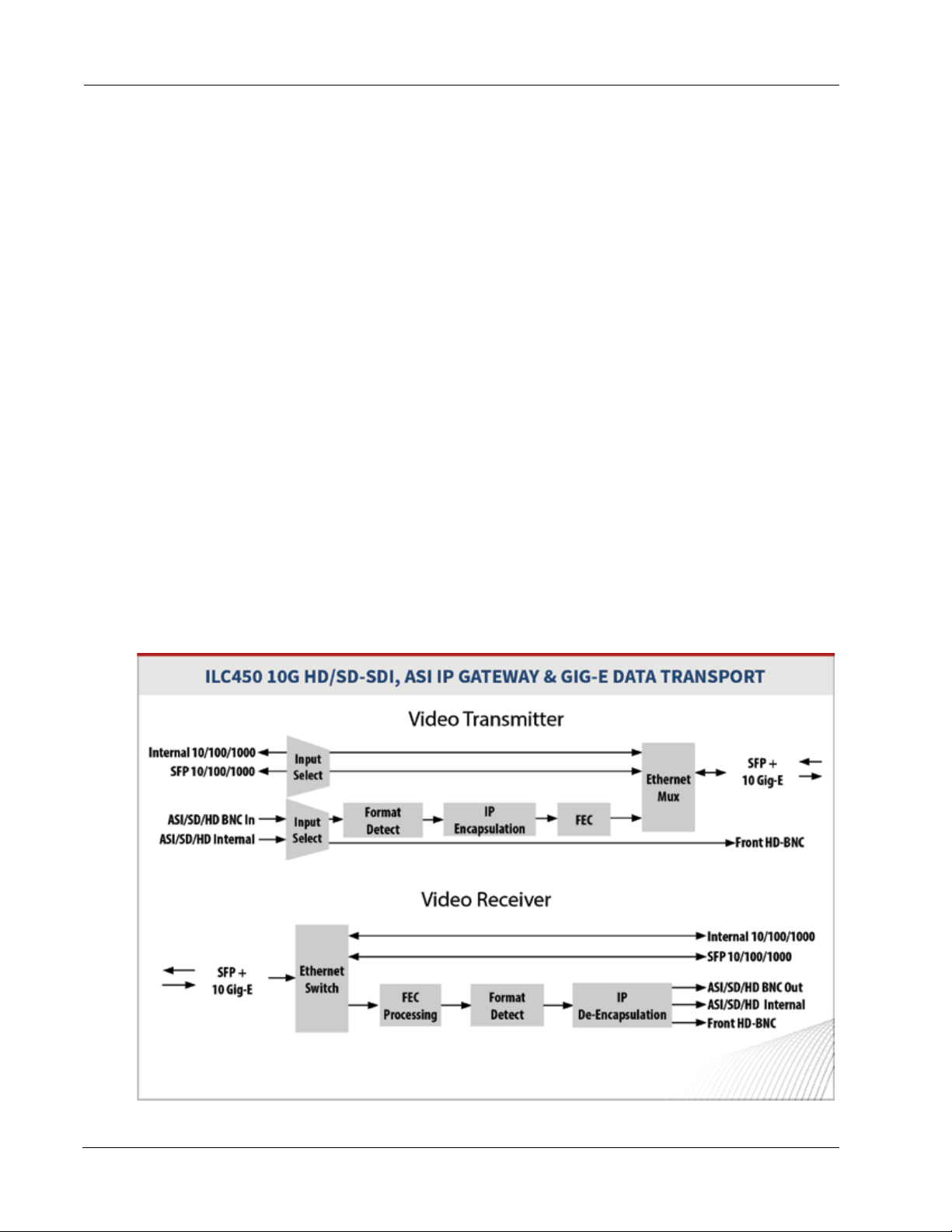
This section provides a functional description of the ILC450 module, including Figure 1, which are functional
block diagrams of the module operating in transmitter and receiver modes.
Figure 1. ILC450 Module Functional Block Diagrams
2 ILC450 Function Module Installation and Operations Manual
Page 13

ILC450 Module Functional Description
Electrical/Optical Inputs and Outputs
The ILC450 module can transport both video and user data and uses the following inputs and outputs:
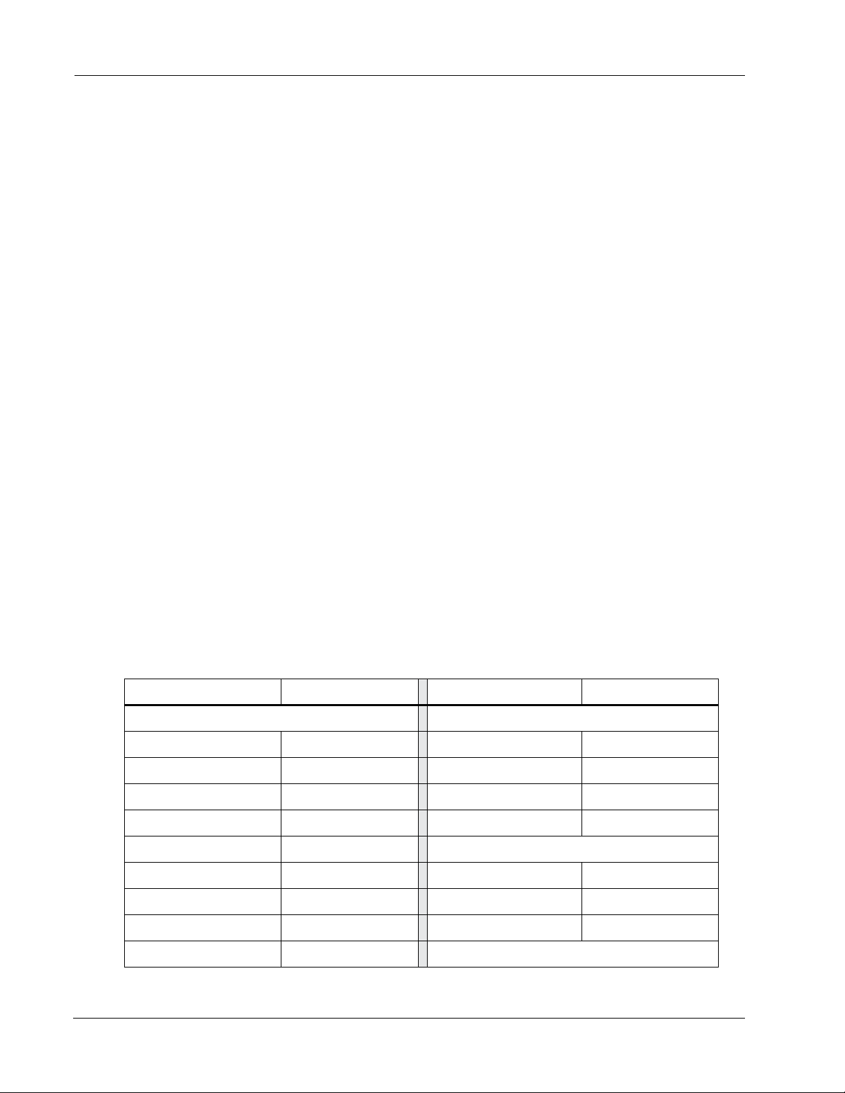
• Two electrical rear panel connections for video data:
– One input BNC connector (IN).
– One output BNC connector (OUT).
• Rear panel SFP+ (10G) and SFP (1G) transceiver sockets:
– 10G—User and video data. The module’s operating mode determines the conguration of trac
through this port as follows:
- Transmit (TX) mode—IP video traverses out of this socket.
- Receive (RX) mode—IP video traverses in to this socket.
– 1G—User data only
The SFP+ and SFP sockets support the following optics:
– WDM (1310 nm, 1550 nm)
– CWDM ITU G.694.2 (Channels 27-61)
– (SFP only) DWDM ITU G.694.1 (Channels 21-60)
The SFP+ and SFP sockets support the following electrical connections:
– (SFP only) RJ45
– (SFP+ only)10GbE passive copper cables
• Backplane connections for sharing signals with other host chassis modules.
• Front panel 75Ohm HD-BNC output jack (MON) for local signal monitoring (see the “Monitoring the
Module Using the Monitor Jack” section on page 16).
ILC450 Function Module Installation and Operations Manual 3
Page 14
ILC450 Sample Applications
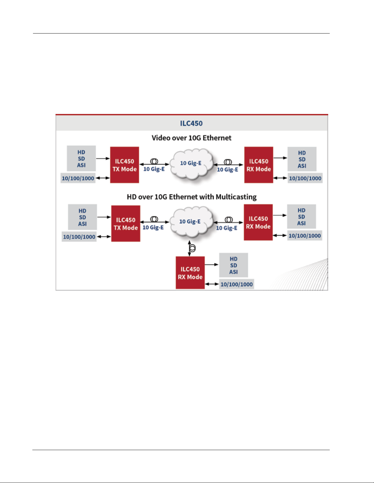
Figure 2 shows how you can congure the ILC450 for transporting either HD-SDI, SD-SDI, or ASI and 1G user
data trac over a 10G Ethernet network or transporting HD video over a 10G Ethernet network with
multicasting.
Figure 2. ILC450 Sample Applications
ILC450 Function Module
4 ILC450 Function Module Installation and Operations Manual
Page 15
Overview of the ILC450 Module
Overview of the ILC450 Module
This section provides an overview of the components that make up the ILC450 module.
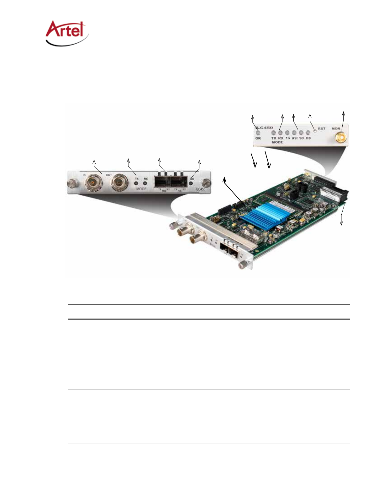
Figure 3. ILC450 Module Major Components
8
5
1
2
3
4
7
6
9
10
Table 1. ILC450 Elements
Item Module Element for details, see...
1 Rear panel BNC connectors for the following electrical
connections:
• IN—Video in
• OUT—Video out
2 Operating mode indicators:
• TX MODE—Transmitter mode
• RX MODE—Receiver mode
3
4 Rear panel alarm indicator OK LED. Understanding the Rear Panel Status LEDs
ILC450 Function Module Installation and Operations Manual 5
+
and SFP sockets:
SFP
+
• 10G—(SFP
• 1G—(SFP) User data only
) User and video data
Cabling the BNC Connections (page 8)
Understanding the Rear Panel Status LEDs
(page 15)
• Cabling the SFP+ and SFP Connections
(page 8)
• Understanding the Rear Panel Status
LEDs (page 15)
(page 15)
Page 16

ILC450 Function Module
Table 1. ILC450 Elements
Item Module Element for details, see...
5 Front panel alarm indicator OK LED. Understanding the Front Panel Status LEDs
6 Front panel transmit (TX) and receive (RX) operating mode
(MODE) indicator LEDs.
7 Front panel status LEDs for the 1G SFP link and ASI, SD, and
HD formats.
8 Front panel reset switch (RESET) to restart the module’s
FPGA.
9
10 Backplane connector that provides power to the module,
Front panel monitor 75Ohm
allows the module to share signals with other function
modules, and is used for alarm and management signals.
(Continued)
HD-BNC output jack (MON).
Installing the ILC450 Module
(page 13)
Using the ILC450 Reset Switch (page 18)
Monitoring the Module Using the Monitor
Jack (page 16)
Conguring the Module (page 8)
The ILC450 module and associated SFP and SFP+ are hot swappable, enabling you to safely install them while
power is applied to the host chassis. Before you install the module, see the ILC450 data sheet for a detailed
description of the module specications, including environmental requirements, that you must adhere to
when installing the module.
Note: You must install the ILC450 module in a chassis that includes IL Manager functionality as the
module requires IL Manager for conguration and monitoring purposes. For more information,
see the “Conguring the Module” section on page 8.
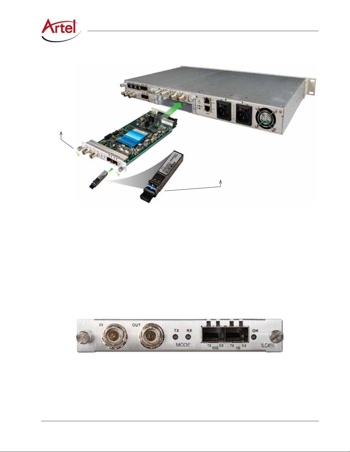
To install the ILC450 module in the host chassis (see Figure 4), perform the following steps:
1. From the back of the chassis, remove the two screws that secure the blank tray to the unused function
module slot.
Use any available function module slot.
2. Slide the module into the chassis slot using the printed circuit board guide rails on either side of the slot.
3. Push the module in until it is rmly seated into the backplane and ush with the chassis.
4. Tighten the two mounting screws that secure the module to the chassis.
+
5. Install the Artel approved SFP
top as shown in Figure 4).
in the 10G socket and the SFP in the 1G socket of the module (handle on
Push the SFP+ and SFP into their designated sockets until they are rmly seated.
6. Insert a blank tray in any unused chassis module slot to maintain proper ventilation.
6 ILC450 Function Module Installation and Operations Manual
Page 17
Cabling the ILC450 Module
Figure 4. ILC450 Module and SFP+ Installation
Mounting Screws (2)
Handle On Top
Cabling the ILC450 Module
This section describes how to cable the external connections of the ILC450 module, which can receive and
transmit external signals over its BNCs, SFP+, and SFP. The cabling conguration that you use depends on your
application.
Figure 5. ILC450 BNC Connectors, 10G SFP+ Socket, and 1G SFP Socket
ILC450 Function Module Installation and Operations Manual 7
Page 18
ILC450 Function Module
Cabling the BNC Connections
To connect to the BNC connectors on the ILC450, use a high quality 75 Ohm precision video coax cable, such
as Belden 1694A cable.
To cable the BNC electrical connections, perform the following tasks:
• Input signal—Connect the coax cable to the ILC450 receive connector (IN) and the source device’s
electrical transmit connector.
• Output signal—Connect the coax cable to the ILC450 transmit connector (OUT) and the destination
device’s electrical receive connector.
Cabling the SFP+ and SFP Connections
When using an optical SFP+ or SFP, use a single mode ber when connecting to the LC connectors of the SFPs.
To cable the 10G (SFP+) and 1G (SFP) connections, perform the following tasks:
1. (Optical only) Remove the safety plug that protects the TX and RX ports.
Cover any unused optical port to keep the port clean.
2. Connect the ber optic or electrical cable between the SFP+ and SFP connectors on the module and the
external source or destination device as follows:
• 10G Socket—(SFP+) User and video data.
• 1G Socket—(SFP) User data only.
Conguring the Module
You congure the ILC450 module operation using the InnityLink Manager (IL Manager) element
management system and the module’s conguration page.
Artel ships the ILC450 congured as follows:
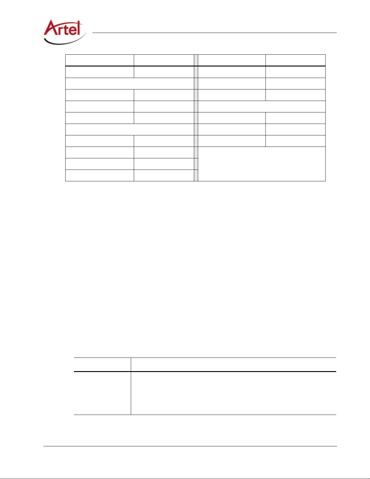
Table 2. ILC450 Factory Settings
Parameter Setting Parameter Setting
Module Settings (for details, see Table 3) Transmitter Settings (for details, see Table 6)
Operational Mode Receive Video Source In BNC
Video Enabled Destination IP Addr 239.0.0.1
1G Disabled Port 4096
Jumbo Frames Enabled Time To Live 128
IP Address 192.168.100.10 HD-SDI FEC Settings
Netmask 255.255.255.0 FEC Mode None
Gateway -- Column 128
Video Alarm Disabled Row 16
10G SFP+ Alarm Enabled SD-SDI FEC Settings
8 ILC450 Function Module Installation and Operations Manual
Page 19
Conguring the Module
Parameter Setting Parameter Setting
1G SFP Alarm Disabled FEC Mode None
Video Signal Types (for details, see Table 4) Column 128
HD-SDI Enabled Row 8
SD-SDI Enabled ASI FEC Settings
ASI Enabled FEC Mode None
Receiver Settings (for details, see Table 5) Column 8
Source IP Addr -- Row 8
Multicast Group 239.0.0.1
Port 4096
Recovery Buer Sm
Prerequisites
To congure the ILC450 module, you must access the IL Manager that manages the module. For details
about accessing and setting up IL Manager, see the InnityLink Manager Setup and Operations Manual.
To congure the ILC450 module operation, perform the following steps:
1. From a browser window, enter the IP address of the IL Manager that manages the module.
The Home page displays.
2. From the Home page menu bar, click Shelf View.
The Shelf View page displays, which shows the rear chassis panel along with the Installed Modules table.
3. From the Installed Modules table, click the ILC450 link listed in the Module Type column.
The Module Status page displays, which shows the module’s current conguration, alarm conditions (if
any), and SFP+ and SFP optical status.
4. From the menu bar, click Conguration.
The Conguration page displays.
5. From the Module Settings panel, congure the following parameters:
Table 3. Module Settings Parameters
Parameter Description
Operational Mode Select the module operating mode (relative to the 10G video circuit) as follows:
+
• Receive—The module receives encapsulated video on the SFP
applies a FEC algorithm, and then de-encapsulates the video.
• Transmit—
connection. Optionally, it may have included FEC data.
The module transmits encapsulated video on the SFP+ TX
RX connection,
ILC450 Function Module Installation and Operations Manual 9
Page 20

ILC450 Function Module
Table 3. Module Settings Parameters
Parameter Description
Video Enable or Disable video transport over the 10G link.
1G From the drop-down list, disable or specify the source of the 1Gbps Ethernet to be
bridged over the 10G link:
• disabled
• SFP
Note: Select only Ethernet ports that are not in use.
Jumbo Frames Enable or disable support for IP Frames that are greater than 1518 bytes and up to 9216
bytes in size.
IP Address Specify the local IP address of the module. This address responds to pings and is the
source IP address of any video transmissions from this module.
Netmask Specify the netmask for the module.
Gateway (Optional) Specify the IP address of the network gateway if needed.
Video Alarm Enable or Disable the alarm for when no video is detected.
10G SFP+ Alarm Enable or Disable the alarm for when the 10Gbps SFP+ is not present.
(Continued)
1G SFP Alarm Enable or Disable the alarm for when the 1Gbps SFP is not present.
6. From the Video Signal Types panel, congure the following parameters:
Table 4. Video Signal Types Parameters
Parameter Description
HD-SDI Enable or Disable detection or output of HD-SDI video format.
SD-SDI Enable or Disable detection or output of SD-SDI video format.
ASI Enable or Disable detection or output of ASI video format.
7. From the Receiver Settings panel, congure the following parameters:
Table 5. Receiver Settings Parameters
Parameter Description
Source IP Addr (Optional) Specify the IP address lter value of the video source. Enter a value using
dotted-decimal format (for example, 10.10.10.1) to only accept video trac from this IP
address. If the video source is another ILC450, this is the IP Address of the transmitter
module.
To disable ltering on the source IP, clear this eld.
10 ILC450 Function Module Installation and Operations Manual
Page 21

Conguring the Module
Table 5. Receiver Settings Parameters
Parameter Description
Multicast Group (Optional) Specify the Multicast Group Address, which is used when the receiver is to join
and receive video from a multicast group. Enter a value using dotted-decimal format (for
example, 225.0.0.1).
Port (Optional) Specify the destination UDP port address.
Valid values are as follows: 1 to 65535. The default is 4096.
Recovery Buer Specify the tolerance of the receive ports as follows:
• Sm—When set to small, stream latency is minimized and late arriving packets are
dropped.
• Lg—When set to large, tolerance for late arriving packets and stream latency are
maximized.
8. From the Transmitter Settings panel, congure the following parameters:
Table 6. Transmitter Settings Parameters
Parameter Description
Video Source Select the video source to transmit from the drop-down list. The options that display in
the list will vary depending on the modules that are installed in the host chassis.
(Continued)
Destination IP Addr Specify the IP address to which the video is sent. When multicast is in use, this is the
Multicast Group Address. Enter a value using dotted-decimal format (for example,
10.10.10.1).
Port (Optional) Specify the module port to use for transmitting IP packets.
Valid destination UDP port numbers are as follows: 1 to 65535. The default is 4096.
Time To Live Specify the number of route hops that a packet may make before it is dropped. Valid
values are as follows: 1 to 255.
HD-SDI FEC Settings Specify the HD-SDI FEC settings. The default FEC mode is None.
The value for FEC Column (L) must be between 1 and 750 for HD-SDI. Values of (L * D) are
further restricted to 3000 for HD-SDI streams.
Valid values are as follows:
• Column Range—1 to 750
• RowColumn Range—4 to 750
• Row * Column—3000
The value for FEC Row (D) must be between 4 and 255. Values of (L * D) are further
restricted to 3000 for HD-SDI streams.
Valid values are as follows:
• Range—4 to 255
• Row * Column—3000
ILC450 Function Module Installation and Operations Manual 11
Page 22

ILC450 Function Module
Table 6. Transmitter Settings Parameters
Parameter Description
SD-SDI FEC Settings Specify the SD-SDI FEC settings. The default FEC mode is None.
The value for FEC Column (L) must be between 1 and 375 for SD-SDI. Values of (L * D) are
further restricted to 1500 for SD-SDI.
Valid values are as follows:
• Column Range—1 to 375
• RowColumn Range—4 to 375
• Row * Column—1500
The value for FEC Row (D) must be between 4 and 255. Values of (L * D) are further
restricted to 1500 for SD-SDI streams.
Valid values are as follows:
• Range—4 to 255
• Row * Column—1500
ASI FEC Settings Specify the ASI FEC settings. The default FEC mode is None.
The value for FEC Column (L) must be between 1 and 20 for ASI. Values of (L * D) are
further restricted to 100 for ASI streams.
Valid values are as follows:
• Range—1 to 20
• Row * Column—100
The value for FEC Row (D) must be between 4 and 20. Values of (L * D) are further
restricted to 100 for ASI streams.
Valid values are as follows:
• Range—4 to 20
• Row * Column—100
(Continued)
9. Click Submit.
The conguration is saved and the module is ready to process video.
12 ILC450 Function Module Installation and Operations Manual
Page 23
Monitoring ILC450 Operations
Monitoring ILC450 Operations
This section describes how to monitor ILC450 operations using the front and rear panel status LEDs or
InnityLink Manager and contains the following topics:
• Monitoring the Module Using the Module Status LEDs (page 13)
• Monitoring the Module Using the Monitor Jack (page 16)
• Monitoring the Module Using IL Manager (page 16)
Monitoring the Module Using the Module Status LEDs
This section describes how to monitor the module’s operations using the front and rear panel LEDs and
contains the following topics:
• Understanding the Front Panel Status LEDs (page 13)
• Understanding the Rear Panel Status LEDs (page 15)
Understanding the Front Panel Status LEDs
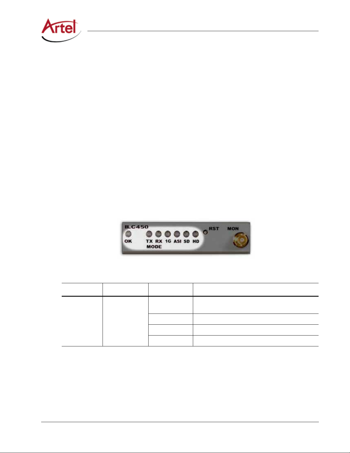
Table 7 describes the states of the ILC450 front panel status LEDs as shown in Figure 6.
Figure 6. ILC450 Front Panel Status LEDs
Table 7. ILC450 Front Panel Status LEDs
LED Indicates . . . State Description
OK Module status O If power is applied to the system, an internal fault with
the module may exist.
Green Normal operation.
Yellow Minor alarm condition exists.
Red Major alarm condition exists.
ILC450 Function Module Installation and Operations Manual 13
Page 24

ILC450 Function Module
Table 7. ILC450 Front Panel Status LEDs
LED Indicates . . . State Description
MODE: TX Transmitter mode
indicator
MODE: RX Receiver mode
indicator
O Receiver mode is selected or Video is disabled (see Table
Green Valid video format as congured in IL Manager.
Yellow No video format detected as congured in IL Manager.
Yellow (ashing) In Unicast mode and no Address Resolution Protocol
Red No link.
O Transmitter mode is selected or Video is disabled (see
Green Valid video detected on the 10G interface with correct
Yellow No video input at receiver detected.
Yellow (ashing) Packet errors detected.
Red No link.
(Continued)
3).
(ARP) reply.
Table 3).
IP conguration.
1G 1G SFP link O 1G not enabled.
Green Link established.
Green (ashing) Link established with activity.
Yellow RX optical power high.
Yellow (ashing) 1G Ethernet enabled, errors detected.
Red No link.
Red (ashing) No SFP installed, low light, or loss of signal.
ASI ASI signal mode
indicator
SD SD signal mode
indicator
O ASI disabled or other rate detected.
Green ASI enabled and ASI detected.
Yellow ASI enabled but no signal detected.
Red Input fault or ASI not enabled but ASI detected.
O SD disabled or other rate detected.
Green SD enabled and SD detected.
Yellow SD enabled but no signal detected.
Red Input fault or SD not enabled but SD detected.
14 ILC450 Function Module Installation and Operations Manual
Page 25
Monitoring ILC450 Operations
Table 7. ILC450 Front Panel Status LEDs
LED Indicates . . . State Description
HD HD signal mode
indicator
O HD disabled or other rate detected.
Green HD enabled and HD detected.
Yellow HD enabled but no signal detected.
Red Input fault or HD not enabled but HD detected.
(Continued)
Understanding the Rear Panel Status LEDs
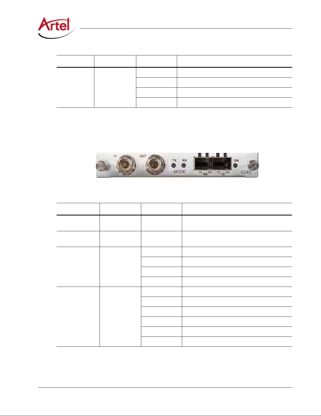
Table 8 describes the states of the ILC450 rear panel status LEDs as shown in Figure 7.
Figure 7. ILC450 Rear Panel Status LEDs
Table 8. ILC450 Rear Panel Status LEDs
LED Indicates . . . State Description
TX Mode Transmitter mode
indicator
RX Mode Receiver
mode indicator
10G TX 10G transmitter
mode status
10G RX 10G receiver
mode status
-- Same operation as the front panel MODE: TX LED
(see Table 7).
-- Same operation as the front panel MODE: RX LED
(see Table 7).
O Not valid during normal operation.
Green Normal operation.
Red TX fault.
Red (ashing) No SFP
O Not valid during normal operation.
Green Link established.
Green (ashing) Link established with activity.
Yellow RX optical power high.
Red No link.
Red (ashing) No SFP
+
installed.
+
installed, low light, or loss of signal.
ILC450 Function Module Installation and Operations Manual 15
Page 26

ILC450 Function Module
Table 8. ILC450 Rear Panel Status LEDs
LED Indicates . . . State Description
1G TX 1G transmitter
mode status
1G RX 1G receiver mode
status
OK Module status -- Same operation as the front panel OK LED (see Table
O 1G not enabled.
Green Normal operation.
Red TX fault.
Red (ashing) No SFP installed.
O 1G not enabled.
Green Link established.
Green (ashing) Link established with activity.
Yellow RX optical power high.
Yellow (ashing) 1G Ethernet enabled, errors
Red No link.
Red (ashing) No SFP installed, low light, or loss of signal.
(Continued)
detected.
7).
Monitoring the Module Using the Monitor Jack
You can monitor the video that the ILC450 receives or transmits by using the front panel monitor jack (MON).
The monitor jack output depends on which mode you congured the module to operate in as follows:
• Transmitter Mode—Output is a copy of the ASI, SD-SDI, HD-SDI signal received on the BNC In
connector on the rear panel.
• Receiver Mode—Output is a copy of the ASI, SD-SDI, HD-SDI signal sent out the BNC Out connector
on the rear panel.
To connect a monitor to the ILC450 to view the transmit or receive signal, connect the monitor cable between
the monitor and the 75 Ohm HD-BNC monitor jack located on the ILC450 front panel (see Figure 3).
Monitoring the Module Using IL Manager
This section shows how to use IL Manager to view the module’s current conguration, major and minor alarm
status, and the optical status of the SFP+ and SFP.
Prerequisites
To monitor the ILC450 module using IL Manager, you must access the IL Manager that manages the
module. For details about accessing and setting up IL Manager, see the InnityLink Manager Setup and
Operations Manual.
16 ILC450 Function Module Installation and Operations Manual
Page 27
Monitoring ILC450 Operations
To monitor the ILC450 module operation, perform the following steps:
1. From a browser window, enter the IP address of the IL Manager that manages the module.
The Home page displays.
2. From the Home page menu bar, click Shelf View.
The Shelf View page displays, which shows the rear chassis panel along with the Installed Modules table.
3. From the Installed Modules table, click the ILC450 link listed in the Module Type column.
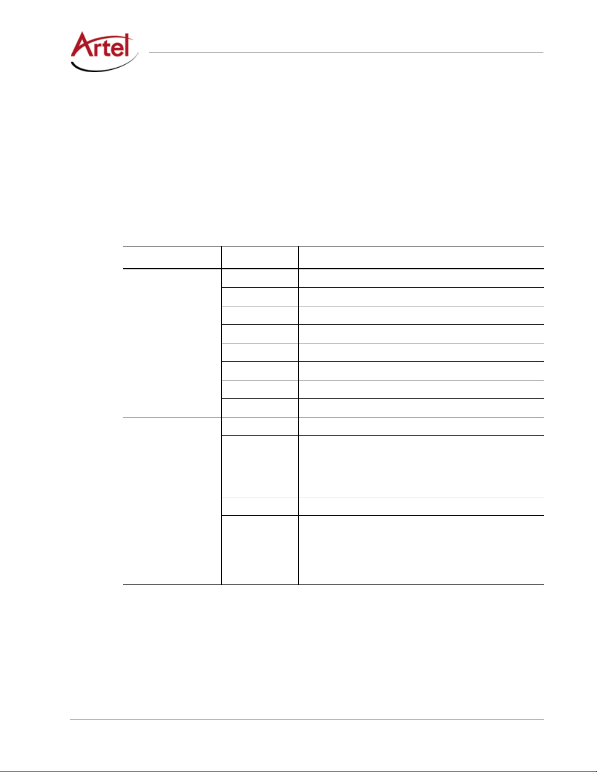
The Module Status page displays, which shows the following information:
Table 9. Module Status Page
Panel Field Description
Current Conguration Mode Congured operating mode: Receiver, Transmitter, or Disabled.
Video Alarms Congured operating state: Enabled or Disabled.
10G SFP+ Alarms Congured operating state: Enabled or Disabled.
1G SFP Alarms Congured operating state: Enabled or Disabled.
Video Congured operating state: Enabled or Disabled.
HD-SDI Congured operating state: Enabled or Disabled.
SD-SDI Congured operating state: Enabled or Disabled.
ASI Congured operating state: Enabled or Disabled.
Trac Status 10G Link Link status: Up or Down.
Video Detected video type: HD-SDI, SD-SDI, or ASI. The displayed video
type includes the word “DISABLED” when the type is congured
as Disabled (see Table 4) or “INVALID” when for example
1080p24 is connected. Just the video type displays when it is
congured as Enabled.
1G Link Link status: Up, Down, or Disabled
1G Connection that the 1G is congured to use as follows:
• SFP—Rear panel 1G SFP socket.
• Backplane—Chassis backplane connection.
ILC450 Function Module Installation and Operations Manual 17
Page 28
ILC450 Function Module
Table 9. Module Status Page
Panel Field Description
Alarms Major Alarms Detected major alarm status of monitored entities as follows:
Minor Alarms Detected minor alarms (if any).
10G SFP+ Status Model Number Assigned model number.
Wavelength Detected value.
Serial Number Assigned serial number.
Rx Power Detected power level of the input signal.
Tx Power Detected power level of the optical transmitter.
1G SFP Status Model Number Assigned model number.
Wavelength Detected value.
Serial Number Assigned serial number.
(Continued)
• Green—No alarms detected.
• Red—Alarm detected that requires immediate attention.
When the alarm indicator is red, IL Manager provides a
descriptive list of any detected alarms to indicate the source
of the problem.
Rx Power Detected power level of the input signal.
Tx Power Detected power level of the optical transmitter.
Routing Labels Channel Labels that you specify for the interfaces using IL Manager.
Type
Label
Description
Using the ILC450 Reset Switch
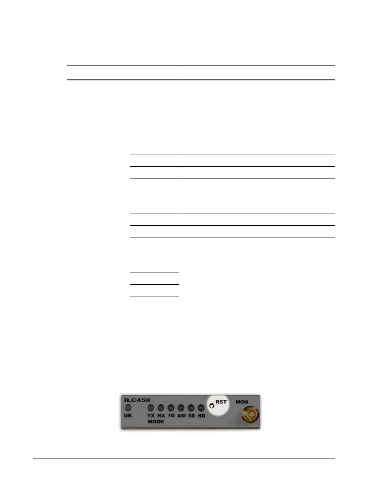
The ILC450 front panel includes a recessed, push-button reset switch (RST) that resets the module, which is
similar to the power-up sequence of the module. Resetting the module interrupts data transmission through
the module but does not erase any user-selected parameters.
Figure 8. ILC450 Reset Switch
To reset the ILC450, press the reset button momentarily.
18 ILC450 Function Module Installation and Operations Manual
Page 29

Removing an SFP, SFP+, or Module
Removing an SFP, SFP+, or Module
You can safely remove either the SFP or SFP+ from a ILC450 module, or the module from the host chassis while
power is applied to the module.
This section contains the following topics:
• Removing an SFP or SFP+ (page 19)
• Removing a Module (page 19)
Removing an SFP or SFP
To remove an SFP or SFP+ from a ILC450 module, perform the following steps:
1. Remove the cables from the SFP or SFP+.
2. Pull down on the SFP or SFP+ handle to dislodge it from the module.
3. Using the handle, pull the SFP or SFP+ out of the module.
+
Removing a Module
To remove a ILC450 module from the host chassis, perform the following steps:
1. Remove the cables from the BNC connectors.
2. Remove the cables from the SFP and SFP+.
3. Loosen the two mounting screws that secure the module to the host chassis.
4. Using the two mounting screws, pull the module out of the host chassis.
Caution
To avoid problems associated with overheating, do not leave a function module slot open when
power is applied to the chassis. Every module slot must contain a module or blank tray to ensure
proper ventilation when power is applied.
ILC450 Function Module Installation and Operations Manual 19
Page 30

20 ILC450 Function Module Installation and Operations Manual
Page 31

Index
A
audience ix
B
backplane connector 6
block diagrams 2
C
cable interfaces 7
caution denition x
components, module 5
congure module 8
conventions x
Customer Service x
E
e-mail address, Customer Service x
F
forward error correction (FEC) 1
forward error correction (FEC), congure 8
front panel
reset switch 18
status LEDs 13
functional description 2
S
SFP and SFP+
cable 8
install 6
remove 19
shipment, damaged x
status LEDs 13
front panel 13
rear panel 15
symbols x
W
warning denition x
M
module
cable 7
components 5
install 6
remove 19
monitor operations 13
O
operations, monitor 13
R
rear panel
connectors 7
status LEDs 15
related documentation ix
reset switch 18
return authorization (RA) number x
ILC450 Function Module Installation and Operations Manual Index-1
Page 32

Index
Index-2 ILC450 Function Module Installation and Operations Manual
Page 33

Page 34
Proven Products, Unrivaled Service,
and Great Support
• Proventechnologyinarugged,reliablepackage
• Supportsallformatsacrossallnetworks
• Intuitiveandsimplifieduserinterfaces
• Integrated,modular,andflexible
• Compactandlowpower
• O-the-shelfdelivery
• Networkrequirementsanalysisanddesignservices
• Trainingandinstallationsupportavailable
• 24x7x365technicalsupportavailable
Artel Video Systems Corp.
5B Lybert y Way, Westford, MA 01886 USA
T: 978-263-5775 | F: 978-263-9755 | www.ar tel.com
Domestic Sales: [email protected]
International Sales: [email protected]
Technical Support: [email protected]
Content subject to change without notice.
©2016
 Loading...