

Page 1
MAnuAL
INFINITYLINK ILC410
SD-SDI or ASI 2 Channel Bi-Directional IP Gateway
Installation and Operations Manual
WWW.ARTEL.COM
Page 2

ii ILC410 Function Module Installation and Operations Manual
Page 3

ILC410 Function Module
SD-SDI or ASI 2 Channel Bi-Directional IP Gateway
Installation and Operations Manual
Document Number: AR200-006410-C00_A
Released: November, 2016
ILC410 Function Module Installation and Operations Manual iii
Page 4

iv ILC410 Function Module Installation and Operations Manual
Page 5

COPYRIGHT
This manual is produced and copyrighted by Artel Video Systems Corporation. Any use or reproduction of the
contents of this manual without the prior written consent of Artel Video Systems Corporation is strictly
prohibited.
NOTICE
All title and copyrights to this document are owned by Artel Video Systems Corporation. No part of the
contents of this document may be reproduced or transmitted in any form or by any means without the written
permission of Artel Video Systems Corporation.
Artel Video Systems Corporation shall not be liable for errors contained herein. Artel Video Systems
Corporation shall not be liable for any damages whatsoever, including, without limitation, damages for loss of
business prots, business interruption, loss of business information, or other pecuniary loss arising out of the
use of this documentation even if Artel Video Systems Corporation has been made aware of the possibility of
such damages.
Information contained in this document is subject to change without notice. While every eort is made to
ensure that the information is accurate as of the publication date, users are reminded to update their use of
this document with documents published by Artel Video Systems Corporation subsequent to this date.
Updates may be available at www.artel.com or by contacting Artel Video Systems Corporation.
Third-party product information is for informational purposes only, and constitutes neither an endorsement
nor a recommendation. Artel Video Systems Corporation assumes no responsibility with regard to the
performance of the third-party products.
Copyright © 2016 by Artel Video Systems Corporation
ALL RIGHTS RESERVED
Printed in U.S.A.
Artel Video Systems Corporation
5B Lyberty Way
Westford, MA 01886
(978) 263-5775
www.artel.com
ILC410 Function Module Installation and Operations Manual v
Page 6

Revision history for the ILC410 Function Module Installation and Operations Manual.
Revision Document Number Date Reason for Change
A
AR200-006410-C00_A
November, 2016 Initial release.
Revision History
vi ILC410 Function Module Installation and Operations Manual
Page 7

About This Manual
Audience...........................................................................................................................................ix
Related Documentation ................................................................................................................ix
Symbols and Conventions .............................................................................................................. x
Artel Customer Service ................................................................................................................... x
ILC410 Function Module
Information About the ILC410 .......................................................................................................1
ILC410 Module Functional Description ........................................................................................2
Video Network Input to IP Network Output ......................................................................................3
IP Network Input to Video Network Output ......................................................................................4
Electrical Inputs and Outputs .................................................................................................................4
Optical Inputs and Outputs .....................................................................................................................5
Ethernet Interface Characteristics ........................................................................................................5
Overview of the ILC410 Module ....................................................................................................6
Installing the ILC410 Module .........................................................................................................8
Cabling the ILC410 Module ..........................................................................................................10
Cabling the BNC Video Network Electrical Connections ............................................................ 10
Cabling the SFP IP Network Connections ........................................................................................10
Cabling Optical SFP Connections ..............................................................................................10
Cabling Electrical SFP Connections ..........................................................................................11
Conguring the ILC410 Module ..................................................................................................11
Labeling the ILC410 Interfaces ....................................................................................................15
Monitoring the ILC410 Module Operation ................................................................................16
Monitoring the ILC410 Status Using the Front Panel ................................................................... 16
Understanding the Status LEDs .................................................................................................17
Using the Monitor Jack ..................................................................................................................18
Monitoring the ILC410 Status Using IL Manager...........................................................................18
Monitoring the ILC410 Statistics Using IL Manager .....................................................................21
Monitoring the ILC410 Diagnostics Data Using IL Manager .....................................................22
Rebooting the ILC410 Module .....................................................................................................22
Removing the SFP and ILC410 Module ......................................................................................23
Removing the SFP....................................................................................................................................23
Removing the ILC410 Module ............................................................................................................. 23
Table of Contents
Index
ILC410 Function Module Installation and Operations Manual vii
Page 8

viii ILC410 Function Module Installation and Operations Manual
Page 9
This manual provides instructions for installing, conguring, and operating the ILC410 function module.
Audience
This manual is intended for the following trained and qualied service personnel who are responsible for
installing and operating the ILC410:
• System installer
• Hardware technician
• System operator
About This Manual
Related Documentation
The following documentation contains material related to the ILC410 function module:
Document Provides . . .
ILC410 Data Sheet Product operating and environmental specications, and regulatory
conformance information.
ILC410 Quick Start Guide Product conguration information using the InnityLink Manager
element management system and descriptions of the front panel
status LED operations.
InnityLink IL6000 Chassis Installation and
Operations Manual
InnityLink IL6000 Data Sheet Overview of the InnityLink media transport chassis options.
InnityLink Manager Setup and Operations
Manual
Overview and installation instructions for the InnityLink media
transport platform chassis options, including the following:
• IL6000 chassis—Installation of this 4-slot chassis, power supplies,
Overview and operating instructions for the InnityLink Manager
element management system.
and function modules.
ILC410 Function Module Installation and Operations Manual ix
Page 10

Symbols and Conventions
This manual uses the following symbols and conventions.
Caution
A caution means that a specic action you take or fail to take could cause harm to the equipment or
to the data transmission.
Warning
A warning describes an action you take or fail to take that could result in death, serious physical injury, or
destruction of property.
Note: Important related information, reminders, and recommendations.
Italics—used for emphasis, for indicating the rst occurrence of a new term, and for book titles
1. Numbered list—where the order of the items is important
• Bulleted list—where the items are of equal importance and their order is unimportant
Artel Customer Service
You can reach Customer Service by e-mail at [email protected] or by telephone:
In the US call (800) 225-0228, then select 1 for technical support.
Outside the US call (978) 263-5775, then select 1 for technical support.
When requesting assistance, please be ready to provide the following information:
• Your name and telephone number
• Product model and serial number
• Brief description of the problem
• List of symptoms
• Steps you have already taken to try to resolve the problem
If the product is damaged
If any portion of the unit is damaged, forward an immediate request to the delivering carrier to perform an
inspection of the product and to prepare a damage report. Save the container and all packing materials until
the contents are veried.
Concurrently, report the nature and extent of the damage to Artel Customer Service so that action can be
initiated to either repair or replace the damaged items.
Do not return any items to Artel until you obtain instructions from Customer Service.
Report the problem or deciency to Customer Service along with the model number and serial number. Upon
receipt of this information, Artel will provide service instructions, or a Return Authorization Number and
shipping information.
x ILC410 Function Module Installation and Operations Manual
Page 11

Information About the ILC410
ILC410 Function Module
SD-SDI or ASI 2 Channel Bi-Directional P Gateway
Information About the ILC410
This manual introduces the ILC410 function module and includes information for installing and conguring
the module. The ILC410 is an IP transport module that can transmit and receive 270Mb/s SDI or ASI video
signals over 1Gigabit Ethernet (GbE) networks that meet SMPTE 2022-1, 2022-2, 2022-5, and 2022-6 standards
for video transmission over IP networks. The ILC410 supports two full duplex SDI or ASI video circuits using
dual input and output BNC connectors. The managed IP network connection is made using a Small Form
Factor Pluggable (SFP) module.
Additional supported features include:
• User-selectable ASI or SDI module operation
• Multicast or unicast operation
• Congurable forward error correction (FEC) for recovery of dropped or corrupted packets
• Congurable tolerance level for late arriving packets
• Withstands burst outages in excess of 3ms
• Artel-approved SFPs available to support the following connection types:
– Optical—Supports 1000Base-LX and 1000Base-ZX formats and WDM, CWDM, and DWDM
wavelengths
– Electrical—Supports 1000Base-T format
• Standard 1000Base-X (IEEE802.3z) methods to indicate the presence of the ber optic link but no
active data being transmitted
You provision and monitor the ILC410 using Artel’s InnityLink Manager (IL Manager), which is an element
management system (EMS). You can also monitor the ILC410 operating status using the module’s status
indicators and front panel monitor jack.
ILC410 Function Module Installation and Operations Manual 1
Page 12
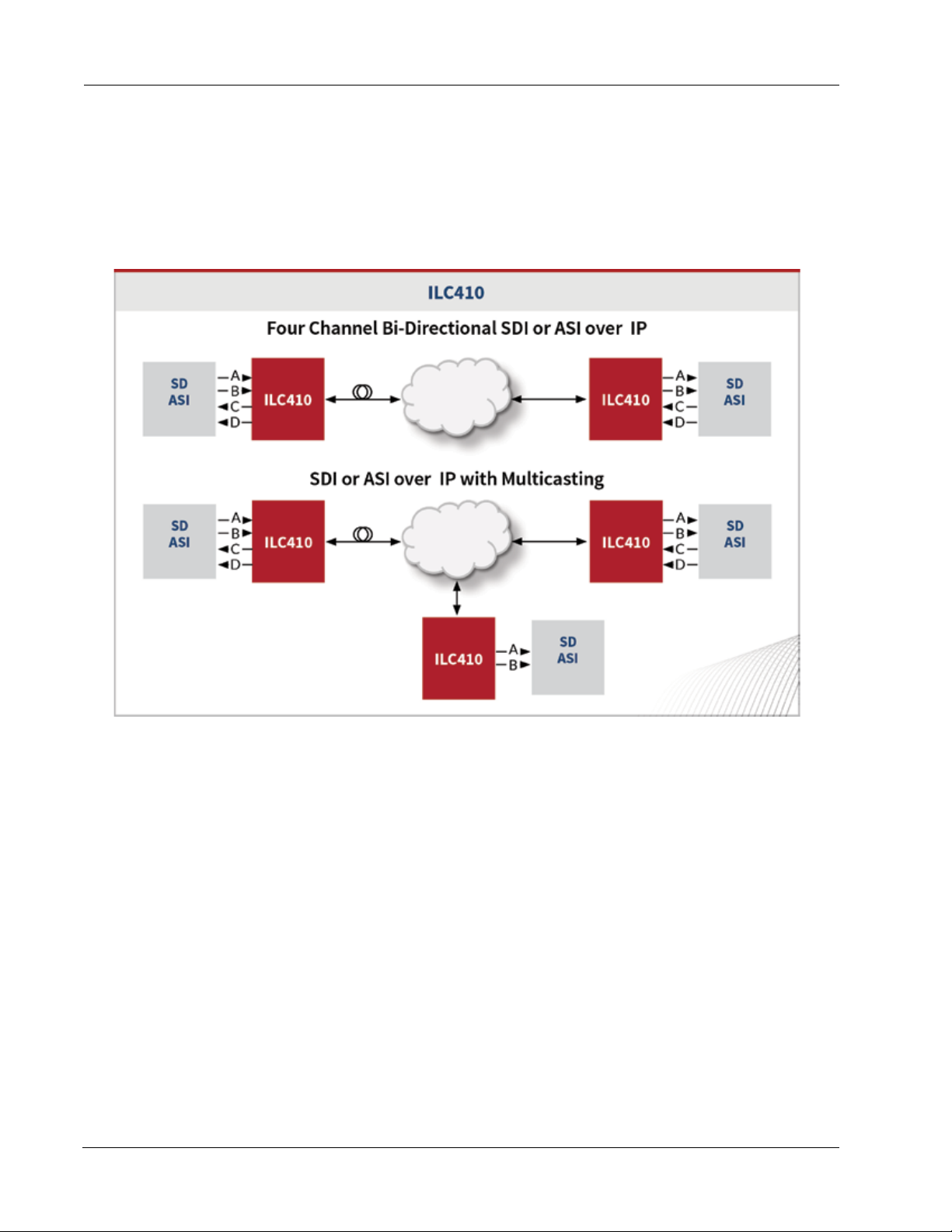
ILC410 Module Functional Description
This section provides a functional description of the ILC410. Figure 1 shows the functional block diagram for
the ILC410.
Figure 1. ILC410 Module Functional Block Diagram
ILC410 Function Module
This section contains the following topics:
• Video Network Input to IP Network Output (page 3)
• IP Network Input to Video Network Output (page 4)
• Electrical Inputs and Outputs (page 4)
• Optical Inputs and Outputs (page 5)
• Ethernet Interface Characteristics (page 5)
2 ILC410 Function Module Installation and Operations Manual
Page 13
ILC410 Module Functional Description
Video Network Input to IP Network Output
This section describes how the ILC410 receives a signal from the video network and processes the signal for
output to a managed IP network (see Figure 1).
Video Network Input
The ILC410 accepts SDI or ASI video signals from the following sources:
• Two 75Ohm BNC input connectors—Located on the rear panel of the module, these are the most
commonly used inputs. The connectors are labeled INA and INB and each one is dedicated to a
specic video channel: CHA or CHB.
• Another chassis module—Signals from other modules in the host chassis can be received through
the backplane.
You select the digital video source using IL Manager (see the “Conguring the ILC410 Module” section on page
11). The ILC410 blocks any video signals that are not of the type selected to process (either SDI or ASI). When
no input signal is present, the front panel’s corresponding IN status LED illuminates yellow (solid) when the
video channel is enabled.
The video input is also made available at the front-panel monitor jack, which is a 75Ohm HD-BNC connector
that allows you to monitor the input and output video signals.
Video Processing
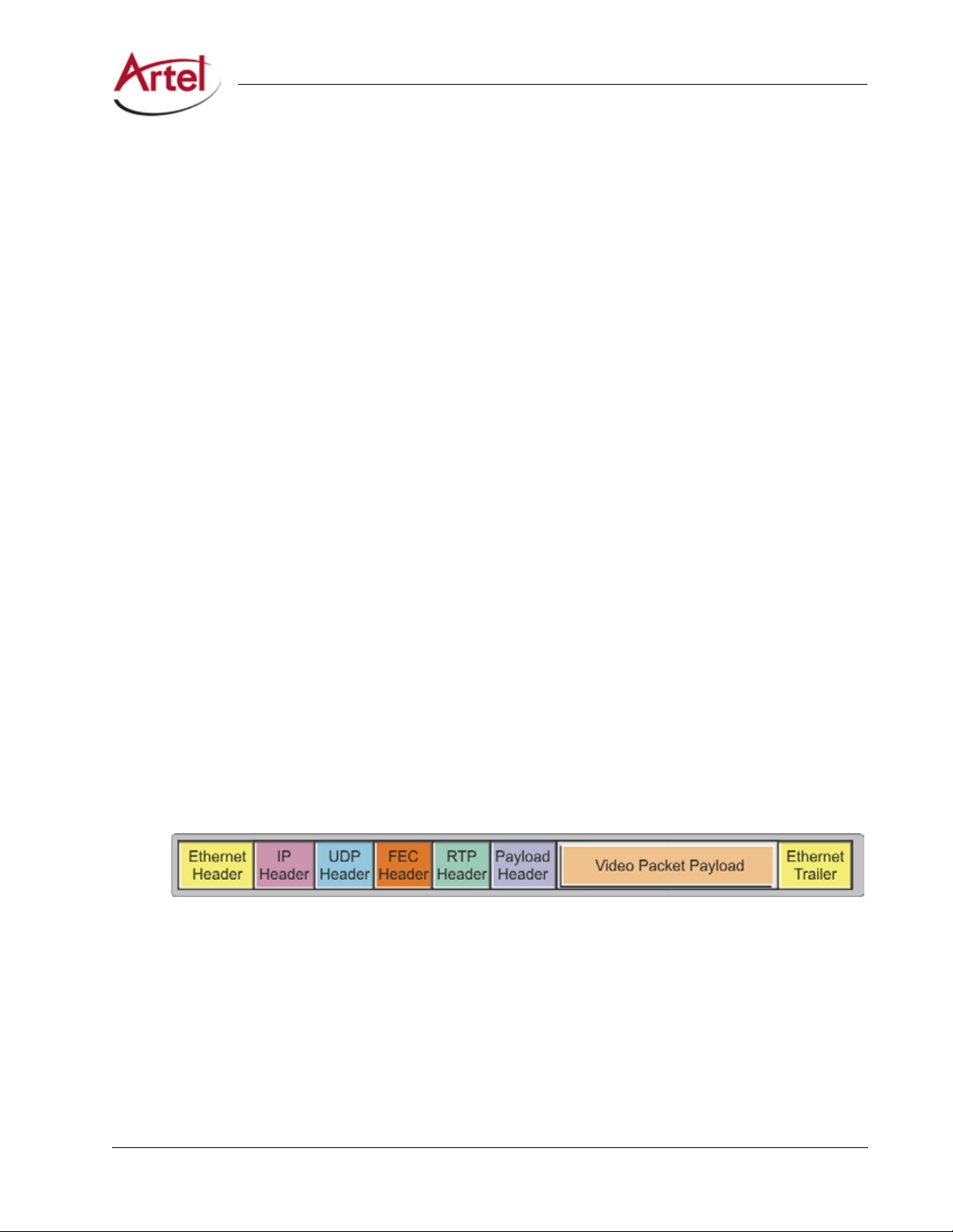
To prepare the input video for transportation over an Ethernet network, the ILC410 processes the input signal
from the video network in accordance with SMPTE 2022-1/2/5/6 as follows:
1. Real-time Transport Protocol (RTP) Encapsulation—Video packet payload and header are encapsulated in
RTP packets.
2. FEC Encoding and Encapsulation—(Optional) FEC is applied and the RTP packets are encapsulated in FEC
packets.
3. User Datagram Protocol (UDP) and IP Encapsulation—FEC packets are encapsulated in UDP packets,
which are then encapsulated in IP packets.
4. Ethernet MAC—IP packets are encapsulated in Ethernet packets.
Figure 2 shows a model of encapsulated video packets ready for transmission over an Ethernet network.
Figure 2. Encapsulating Video Packets for Ethernet Networks
IP Network Video Output
The ILC410 transmits encapsulated video to the managed IP network using an SFP.
ILC410 Function Module Installation and Operations Manual 3
Page 14

ILC410 Function Module
IP Network Input to Video Network Output
This section describes the process by which the ILC410 receives encapsulated video signals from a managed IP
network and outputs the decapsulated video signals to a video network (see Figure 1).
IP Network Input
The ILC410 receives encapsulated video from the managed IP network using an SFP, which can be:
• Optical—LC connector with optics that support WDM, CWDM, or DWDM wavelengths.
• Electrical—RJ45 connector.
Video Processing
The ILC410 processes the SMPTE 2022-1/2/5/6 from the IP network as follows:
1. Ethernet MAC—Ethernet header and trailer are removed from the IP packets.
2. IP and UDP Decapsulation—IP header and then the UDP header are removed.
3. FEC Decoding and Decapsulation—(Optional) FEC is applied to recover lost packets.
4. RTP Decapsulation—RTP header is removed.
Video Network Output
The ILC410 outputs the decapsulated SDI or ASI video signals to the following destinations:
• Two 75Ohm BNC output connectors—Located on the rear panel of the module, these are the most
commonly used outputs. The connectors are labeled OUTA and OUTB and each one is dedicated to a
specic video channel: CHA or CHB.
• Another chassis module—Output signals can be transmitted to other modules in the chassis through
the backplane connector.
You select the digital video destination using IL Manager (see the “Conguring the ILC410 Module” section on
page 11).
The video output is also made available at the front-panel monitor jack, which is a 75Ohm HD-BNC connector
that allows you to monitor the input and output video signals.
Electrical Inputs and Outputs
The ILC410 uses the following electrical inputs and outputs:
• Rear panel BNC connectors.
• Backplane connector.
• Rear panel SFP socket that can accommodate an electrical SFP with RJ45 connector (if an optical SFP
is not used).
• Front-panel monitor jack, which is a 75Ohm HD-BNC connector that allows you to monitor the input
and output video signals.
4 ILC410 Function Module Installation and Operations Manual
Page 15

ILC410 Module Functional Description
Optical Inputs and Outputs
A single SFP socket provides the ILC410 optical Ethernet interface (if an electrical SFP is not used). The optical
SFP modules use LC connectors. Optical performance is dependant on the quality of your optical ber and
ber interconnects and on the selected SFP module, which must be specically qualied by Artel. Consult
Artel for available SFP options.
Ethernet Interface Characteristics
The ILC410 Ethernet interface characteristics are as follows:
• Operates with 1 GbE full-duplex Ethernet only.
• Supports Internet Protocol version 4 (IPv4) only (IPv6 is not supported).
• Supports the following networking protocols: ARP, ICMP, IP, UDP, TCP, and RTP.
• Employs static IP addresses for the video and control IP addresses (DHCP is not supported). Transmit
channels A and B each have a dedicated, user-dened IP address or multicast group specication
register. Receive channels A and B each have one user-dened receive IP address or receive multicast
group register and a multicast source IP address register.
Note: Artel ships the ILC410 congured with a set of default IP addresses and port numbers.
You must congure these items with values that are specic to your IP network (see the
“Conguring the ILC410 Module” section on page 11).
ILC410 Function Module Installation and Operations Manual 5
Page 16
4
5
6
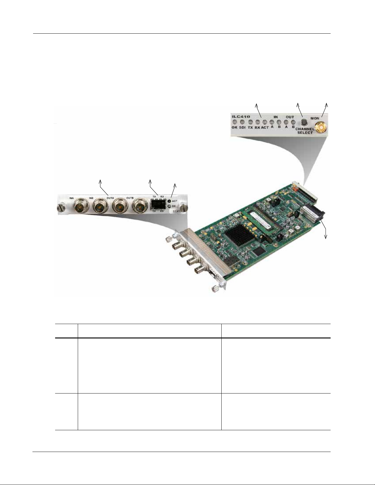
Overview of the ILC410 Module
This section provides an overview of the major components that make up the ILC410.
Figure 3. ILC410 Module Major Components
ILC410 Function Module
1
Table 1 describes the components called out in Figure 3.
Table 1. ILC410 Elements
Item ILC410 Element for details, see...
1 BNC connectors for receiving and transmitting SDI or ASI
video as follows:
• INA—Input channel A
• INB—Input channel B
• OUTA—Output channel A
• OUTB—Output channel B
2
3
Cabling the BNC Video Network Electrical
Connections (page 10)
7
2 SFP socket for the following optical or electrical
connections:
• TX—Transmit
• RX—Receive
6 ILC410 Function Module Installation and Operations Manual
Cabling the SFP IP Network Connections
(page 10)
Page 17

Overview of the ILC410 Module
Table 1. ILC410 Elements
Item ILC410 Element for details, see...
3 Rear panel status LEDs:
• ACT—SFP Ethernet port status indicator
• OK—Alarm indicator
4 Front panel status LEDs:
• OK—Alarm indicator
• SDI—Video type indicator (SDI-On/ASI-O )
• TX—SFP transmit status indicator
• RX—SFP receive status indicator
• ACT—SFP Ethernet port status indicator
• IN—Receive signal status indicators for channels A and
B
• OUT—Transmit signal status indicators for channels A
and B
5 Front panel Channel Select switch—Allows you to select the
receive or transmit signal to monitor or reset the module.
6 Front panel monitor 75 Ohm HD-BNC output jack.
(Continued)
Understanding the Status LEDs (page 17)
Understanding the Status LEDs (page 17)
Using the Monitor Jack (page 18)
7 Backplane connector—Provides power to the module,
allows the module to share signals with other function
modules, and is used for alarm and management signals.
N/A
ILC410 Function Module Installation and Operations Manual 7
Page 18

Installing the ILC410 Module
The ILC410 and associated SFP are hot swappable, enabling you to safely install them while power is applied
to the host chassis.
Note: Before you install the ILC410, see the ILC410 data sheet for a detailed description of the module
specications including environmental requirements that you must adhere to when installing
the module.
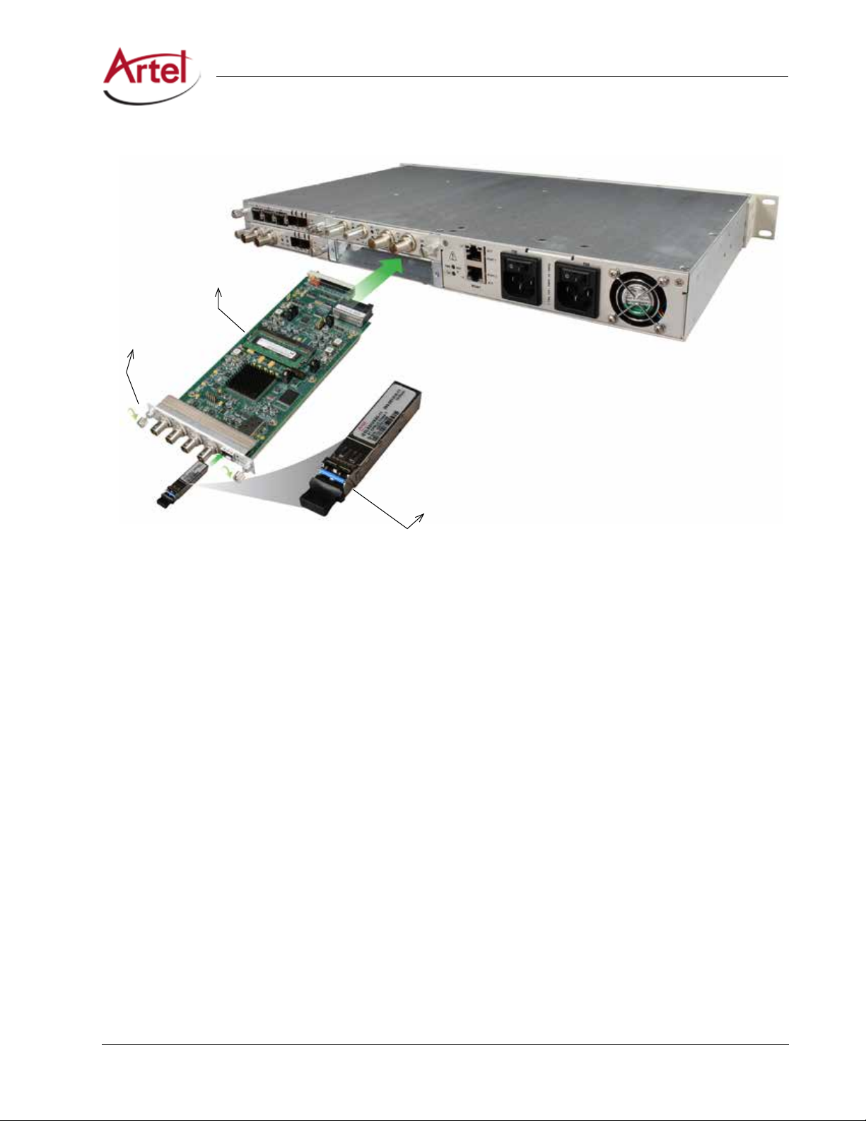
To install the ILC410 in the host chassis, perform the following steps:
1. From the back of the chassis (see Figure 4), remove the two screws that secure the blank tray to one of the
unused function module slots (if necessary).
You can use any available function module slot.
2. Slide the ILC410 into the slot using the printed circuit board guide rails on either side of the slot.
3. Push the ILC410 in until it is rmly seated into the backplane and ush with the chassis.
4. Tighten the two mounting screws that secure the module to the chassis.
Note: Failure to properly secure the ILC410 to the chassis with the two mounting screws can result
in disconnecting the module from the backplane when you attach a cable to the monitor
connector located on the front panel.
ILC410 Function Module
5. Install the Artel-approved SFP into the ILC410 with the handle on top as shown in Figure 4.
Push the SFP into the socket located on the right side of the function module until it is rmly seated in the
socket.
Note: When you do not install an SFP, the TX LED located on the ILC410 front panel will ash. See
Table 5 for other LED status indications
8 ILC410 Function Module Installation and Operations Manual
Page 19
Installing the ILC410 Module
Figure 4. ILC410 Module Installation
ILC410 Module
Mounting Screws
(2)
SFP
(handle on top)
Note: Insert a blank tray in any unused chassis module slots to maintain proper ventilation.
ILC410 Function Module Installation and Operations Manual 9
Page 20
Cabling the ILC410 Module
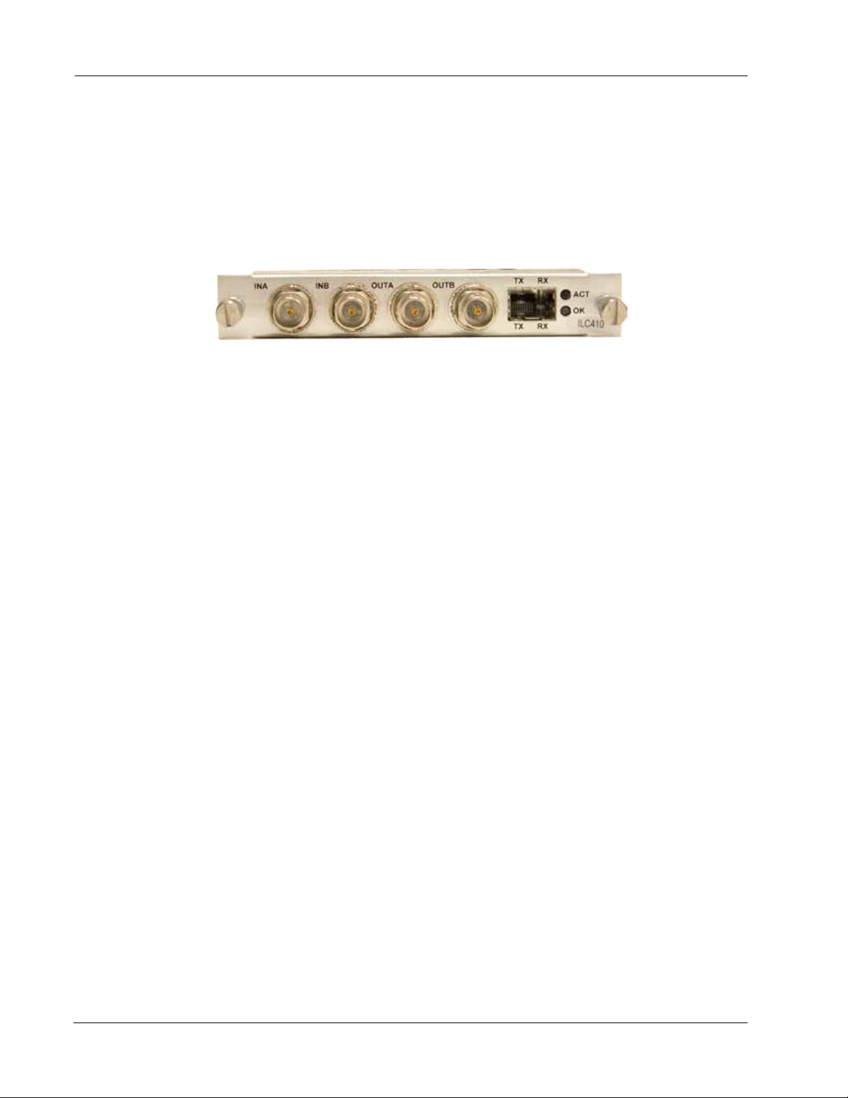
The ILC410 can transmit and receive video network signals over the BNC electrical cable connections. For IP
network connectivity, the ILC410 transmits and receives signals through an SFP using either electrical (copper)
or ber optic cable connections. The cabling conguration that you use depends on your application. All
external connectors are located on the rear panel of the ILC410.
Figure 5. ILC410 BNC Connectors and SFP Socket
Note: When handling ber optic cables, adhere to the standard safety practices for handling a Class 1
laser product.
This section contains the following topics:
• Cabling the BNC Video Network Electrical Connections (page 10)
• Cabling the SFP IP Network Connections (page 10)
ILC410 Function Module
Cabling the BNC Video Network Electrical Connections
Use a high quality 75Ohm precision video coax cable, such as Belden 1694A cable, when cabling to the ILC410
BNC connectors.
Cabling the SFP IP Network Connections
The type of SFP that you use determines whether you are connecting to the managed IP network using an
electrical or an optical connection.
This section contains the following topics:
• Cabling Optical SFP Connections (page 10)
• Cabling Electrical SFP Connections (page 11)
Cabling Optical SFP Connections
Use a single mode ber when connecting to the LC connectors of the ILC410 SFP.
To cable the optical connections, perform the following tasks:
1. Remove the SFP safety plug that protects the TX and RX ports.
Cover any unused optical port to keep the port clean.
2. Cable the optical connections as follows:
• Receive signal—Connect the ber optic cable between the IP network optical transmit connector
and the SFP receive optical connector (RX) on the ILC410.
10 ILC410 Function Module Installation and Operations Manual
Page 21

Conguring the ILC410 Module
• Transmit signal—Connect the ber optic cable between the IP network optical receive connector
and the SFP transmit optical connector (TX) on the ILC410.
Cabling Electrical SFP Connections
To connect to the SFP’s RJ45 connector, use a CAT5e cable.
Conguring the ILC410 Module
This section describes how to congure the operation of the ILC410 using IL Manager.
Prerequisites
• You must use ILManager to congure the ILC410. Refer to the InnityLink Manager Setup and
Operations Manual.
• Your network administrator must provide you with the following items for conguring the ILC410 IP
network connection:
– IP Address
– Netmask
– Gateway
– VLAN
– VLAN Priority
See Table 2 for item descriptions.
To congure the ILC410, perform the following steps:
1. From a browser window, enter the IP address of the IL Manager that manages the module.
The Home page appears.
2. From the Home page menu bar, click Shelf View.
The Shelf View page appears, which shows the rear chassis panel along with the Installed Modules table.
3. From the Installed Modules table, click the ILC410 link listed in the Module Type column.
The Module Status page appears, which shows the module’s current conguration and alarm conditions if
any exist.
4. From the menu bar, click Conguration.
The Conguration page appears.
ILC410 Function Module Installation and Operations Manual 11
Page 22

ILC410 Function Module
5. Congure the module operation as follows (click ? for related online help):
• From the Module Settings pane, congure the module settings as described in Table 2.
Table 2. Module Settings
Item Description
IP Address ILC410 IP address. This address responds to Internet Control Message Protocol (ICMP)
echo requests (pings) and is the source IP address of video transmissions. Enter a value
using dotted-decimal format (for example, 10.10.10.1).
Note: The module IP address is independent of the video Destination IP Address that
you congure for the transmitter and the video Source IP Address that you
congure for the receiver.
Netmask Subnet mask for the ILC410 IP address (for example, 255.255.0.0).
Gateway Network gateway IP address. If the network does not have a gateway, leave this eld
blank.
Auto-Negotiate Auto-negotiate function for the ILC410 Ethernet interfaces, which are set to operate at
1GbE, full-duplex only. Choose one of the following:
• Enable—The ILC410 does the following:
– Auto-negotiates a link with another device set to auto-negotiate and 1GbE,
full-duplex.
– Attempts to link with a device that is not set to auto-negotiate.
Note: Even when a link appears to be made, the ILC410 does not
reliably transfer data.
• Disable—The ILC410 does the following:
– Establishes a link with another device that is not set to auto-negotiate but is
set to 1GbE, full duplex.
– Attempts to link with another device that is set to auto-negotiate.
Note: Even when a link appears to be made, the ILC410 does not
reliably transfer data.
VLAN VLAN operating state. When enabled, the ILC410 appends the specied VLAN ID to the
outgoing Ethernet frames. Choose one of the following:
• Enable
• Disable
VLAN ID VLAN identier that the ILC410 appends to the outgoing Ethernet frames. Enter a value
from 0 to 4095.
Note: This parameter requires the VLAN setting to be Enable.
VLAN Priority Class of service (CoS), or trac prioritization, assigned to the trac on the VLAN. Enter a
value from 0 to 7, with 0 being the lowest priority and 7 the highest.
Note: This parameter requires the VLAN setting to be Enable.
12 ILC410 Function Module Installation and Operations Manual
Page 23

Conguring the ILC410 Module
Table 2. Module Settings
Item Description
Video Mode Video mode for Channels A and B. Choose one of the following:
• ASI
• SD/SDI
Video Alarm Video alarm operating state. When enabled, the ILC410 issues an alarm when the active
video signal is lost. Choose one of the following:
• Enable
• Disable
SFP Alarm SFP alarm operating state. When enabled, the ILC410 issues an alarm when the SFP is
not installed. Choose one of the following:
• Enable
• Disable
• From the Receiver Channel A and B panes, congure the receiver settings as described in Table 3.
Table 3. Receiver Channel Settings
Field Description
(Continued)
Receiver Operating state of the receivers for Channels A and B. When enabled, the
ILC410 can receive video on the associated channel. Choose one of the
following:
• Enable
• Disable
Source IP Addr IP address of the source ILC410 or SMPTE 2022-based Ethernet transmitter.
Enter a value using dotted-decimal format (for example, 10.10.10.1).
Multicast Group Special IP multicast group address that the ILC410 is to receive trac from
during multicast reception. Enter a value using dotted-decimal format (for
example, 10.10.10.1).
Port Logical TCP/IP port address on which the ILC410 receives IP packets. Enter a
value from 1 to 65535.
Recovery Buer Size of the buer that handles late arriving and misordered packets. The ability
of the ILC410 to handle late or misordered buers increases with the size of the
buer. Choose one of the following:
• Sm (small)
• M (medium)
• Lg (large)
Recovery buer size and FEC Mode settings determine ILC410 latency.
ILC410 Function Module Installation and Operations Manual 13
Page 24

ILC410 Function Module
• From the Transmitter Channel A and B panes, congure the transmitter settings as described in Table
4.
Table 4. Transmitter Channel Settings
Field Description
Transmitter Operating state of the transmitters for Channels A and B. When enabled, the
ILC410 can transmit video on the associated channel. Choose one of the
following:
• Enable
• Disable
Video Source Source connection that the ILC410 uses for the video that it receives and
processes. Choose one of the following:
• Backplane chassis slot. The available choices depend on the host chassis
type as follows:
– For IL6000, displays backplane slots 1–4.
• BNC IN connector—InA or InB depending on the channel being
congured.
Destination IP Addr IP address of the destination ILC410 or SMPTE 2022-based Ethernet receiver.
Enter a value using dotted-decimal format (for example, 10.10.10.1).
Port Logical port address on which the ILC410 transmits IP packets. Enter a value
from 1 to 65535.
Type of Service Type of service (ToS) bits for the data that the ILC410 transmits. ToS species
the IP priority level with which to route trac through the IP network to the
destination device. Enter a value from 0 to 7. The higher the value, the better
the service.
FEC Mode Forward error correction (FEC) settings. Choose one of the following:
• Col—Enables column FEC in which packets are mapped into columns. In
the Column eld, specify the number of columns. Valid ranges are as
follows:
– 1 to 1023 (this is the entire valid range).
– 1 to 1020 for interoperability.
– 4 to 1020 for interoperability when using RowColumn FEC.
• RowCol—Enables row/column FEC in which packets are mapped into a
matrix of rows and columns. In the Column and Row elds, specify the
number of columns and rows. The maximum matrix size allowed is as
follows:
ROW X Col = 1500
• None—Disables FEC.
The FEC Mode and Recovery Buer settings determine ILC410 latency.
ASI Bandwidth Limit (ASI mode only) Maximum ASI bandwidth allowed. If the bandwidth exceeds
the specied limit, the trac is throttled. Enter the ASI bandwidth limit.
14 ILC410 Function Module Installation and Operations Manual
Page 25

Labeling the ILC410 Interfaces
Table 4. Transmitter Channel Settings
Field Description
M2TS Packing (ASI mode only) Number of MPEG-2 Transport Stream (M2TS) frames per IP
frame.
Inserting a small number of M2TS frames per IP frame minimizes the amount
of lost video frames when an IP frame is dropped or corrupted; however, this
packing method reduces bandwidth eciency because of the overhead
associated with the additional IP frames required to transport a set amount of
M2TS frames.
Inserting a large number of M2TS frames per IP frame increases the possibility
of losing larger amounts of video frames for each dropped or corrupted IP
frame; however, this packing method increases bandwidth eciency because
it takes fewer IP frames to transport a set amount of M2TS frames.
Choose one of the following values:
• 1—Least ecient use of bandwidth but least susceptible to lost video
when IP frames are dropped or corrupted.
• 4—Moderately ecient use of bandwidth and moderately susceptible to
lost video.
• 7—Most ecient use of bandwidth but greatest susceptibility to lost
video when IP frames are dropped or corrupted.
(Continued)
6. Click one of the following buttons:
• Submit—Saves the displayed conguration information.
• Reload Page—Ignores any modications that you made and reloads the module’s current
conguration.
Labeling the ILC410 Interfaces
You can assign custom labels and descriptions to each of the ILC410 input and output interfaces, which makes
it easier for you to track the source and destination of the trac that is routed through the ILC410.
To assign labels to the ILC410 interfaces, perform the following steps:
1. From the IL Manager client device, access the IL Manager home page (see the InnityLink Manager Setup
and Operations Manual).
2. From the IL Manager home page, click Shelf View.
The Shelf View page appears, which displays a table of the installed function modules, including the
installed ILC410 modules.
3. From the Module Type column of the Shelf View page, click the ILC410 to congure.
The ILC410 Module Status page appears, displaying the module’s current conguration.
4. From the ILC410 Module Status page, click Edit Labels.
The ILC410 Edit Labels page appears.
ILC410 Function Module Installation and Operations Manual 15
Page 26
ILC410 Function Module
5. Dene a label and description for each interface as follows using the specied number of alphanumeric
characters (special characters are permitted):
• Name—16 characters maximum.
• Description—40 characters maximum.
6. Click one of the following buttons:
• Submit—Saves the displayed label information.
• Reset—Resets the information that you modied back to its previous value.
Monitoring the ILC410 Module Operation
You can monitor the ILC410 operations locally using the front panel LEDs and monitor connector or remotely
using IL Manager.
This section contains the following topics:
• Monitoring the ILC410 Status Using the Front Panel (page 16)
• Monitoring the ILC410 Status Using IL Manager (page 18)
• Monitoring the ILC410 Statistics Using IL Manager (page 21)
• Monitoring the ILC410 Diagnostics Data Using IL Manager (page 22)
Monitoring the ILC410 Status Using the Front Panel
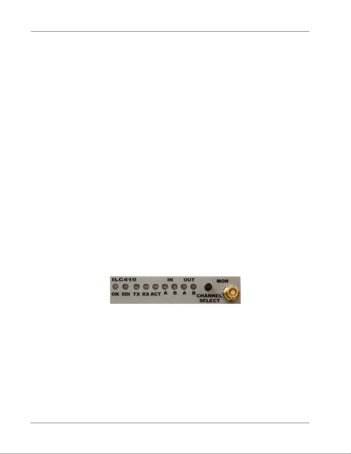
This section describes how to monitor the ILC410 operations using the front panel LEDs and the monitor
connector.
Figure 6. ILC410 Status LEDs and Monitor Connector
This section contains the following topics:
• Understanding the Status LEDs (page 17)
• Using the Monitor Jack (page 18)
16 ILC410 Function Module Installation and Operations Manual
Page 27
Monitoring the ILC410 Module Operation
Understanding the Status LEDs
Table 5 describes the dierent states of the ILC410 status LEDs as shown in Figure 6.
Table 5. ILC410 Status LEDs
LED Indicates . . . State Description
OK
(also
located on
the rear
panel (see
Figure 5))
SDI Detected video type O ASI operating mode.
TX SFP transmitter status Green Normal operation; optical output on, able to send IP
RX SFP receiver status Green Normal operation; incoming Rx signal detected.
ILC410 module status O If power is applied to the system, an internal fault with
Green Normal operation.
Yellow Minor alarm condition exists.
Red Major alarm condition exists.
Green SDI operating mode.
Red SFP Tx fault detected (major alarm).
Red (ashing) SFP not installed.
the ILC410 may exist.
trac.
Yellow (ashing) Optical Rx power too high.
Red (ashing) Optical Rx SFP power too low/LOS or SFP not installed.
ACT
(also
located on
the rear
panel (see
Figure 5))
IN A and B TX channel status O Channel is disabled.
SFP Ethernet activity status O No Ethernet link detected.
Green Ethernet link present.
Green (ashing) Ethernet link activity detected.
Green Video is received.
Yellow No signal detected.
Red Improper video input.
Red (ashing) DVB-ASI rate limited.
ILC410 Function Module Installation and Operations Manual 17
Page 28

ILC410 Function Module
Table 5. ILC410 Status LEDs
LED Indicates . . . State Description
OUT A and BRX channel status O Channel is disabled.
(Continued)
Green Video is received.
Green (ashing) Successful FEC.
Green/Red
(alternate)
Yellow Provisioned but not receiving IP packets.
Red Improper video input.
Unsuccessful FEC.
Using the Monitor Jack
You can monitor the video that the ILC410 receives or transmits by using the front panel monitor port and
associated Channel Select push button switch.
To connect a monitor the ILC410 to view the transmit and receive signals on Channels A and B, perform the
following steps:
1. Connect the monitor cable between the monitor and the 75 Ohm HD-BNC monitor jack located on the
ILC410 front panel (see Figure 6).
2. Push the CHANNEL SELECT button switch to sequentially monitor each channel’s receive and transmit
signals. When you push the switch, the selected signal’s front panel LED blinks for 5 seconds to show
which channel is being monitored. To advance to the next signal, push the switch again while it is
blinking.
Note: The CHANNEL SELECT button switch can also be used to reboot the ILC410 (see the
“Rebooting the ILC410 Module” section on page 22).
Monitoring the ILC410 Status Using IL Manager
IL Manager’s ILC410 Module Status page provides a detailed view of the ILC410 module’s current
conguration and operating status, including the operating states of channels A and B and any detected
alarm conditions.
Note: Each of the reported parameter values has either been assigned or installed as part of the
manufacturing process, detected by the ILC410, or congured by you. For more information
about the congured parameters, see the “Conguring the ILC410 Module” section on page
11.
To display the ILC410 Module Status page, perform the following steps:
1. From the IL Manager client device, access the IL Manager home page (see the InnityLink Manager Setup
and Operations Manual).
2. From the IL Manager home page, click Shelf View.
The Shelf View page appears, which displays a table of the installed function modules, including the
installed ILC410 modules.
18 ILC410 Function Module Installation and Operations Manual
Page 29

Monitoring the ILC410 Module Operation
3. From the Module Type column of the Shelf View page, click the ILC410 to congure. The ILC410 Module
Status page appears, displaying the module’s current conguration and operations.
See the following sections for information about each pane in the ILC410 Module Data page:
• Current Conguration Pane (page 19)
• Channels A and B Status Panes (page 19)
• Alarms Pane (page 20)
• SFP Status (page 20)
• Routing Labels Status (page 20)
Current Conguration Pane
Table 6 describes the content of this pane.
Table 6. Current Conguration Status
Field Description
Video Mode Mode setting: ASI or SDI.
SFP Alarms Alarm operating state: Enabled or Disabled.
Video Alarms Alarm operating state: Enabled or Disabled.
Backplane outputs Receiver backplane output slot number:
• Slots 1–4 (IL6000 chassis)
Channels A and B Status Panes
Table 7 describes the content of this pane.
Table 7. Channels A and B Status
Field Description
IP Link IP link status:
• OK—Link established.
• NONE—No link established.
Receive Video Video receive status:
• DISABLED—Receive function disabled.
• ENABLED—Receive function enabled.
• NOT DETECTED—Video not detected.
Video Input Video input status:
• DETECTED—Video input detected.
• NOT DETECTED—Video input not detected.
ILC410 Function Module Installation and Operations Manual 19
Page 30

ILC410 Function Module
Table 7. Channels A and B Status
Field Description
Transmit Video Transmit video state:
• LOCKED—Signal is received or transmitted.
• UNLOCKED—Indication that the input signal rate is outside the standard rate
requirements or the signal type does not match the selected mode.
• DISABLED—No video data can be received or transmitted.
Transmit Source Transmit source connection:
• BNC—Rear panel BNC.
• Slot number port number—Backplane selection (for example, Slot 1 port C)
Alarms Pane
Table 8 describes the content of this pane.
Table 8. Alarms Status
Field Description
Major Alarms Detected major alarms (if any).
Minor Alarms Detected minor alarms (if any).
SFP Status
Table 9 describes the content of this pane.
Table 9. Optical Status Pane
Field Description
Model Number SFP model number.
Wavelength/Cable Type Wavelength in nm or Cable Type CAT 5.
Serial Number SFP serial number.
SFP Type SFP information depending on SFP type:
• Copper SFP: Copper SFP present
• Optical SFP:
– RX power in dBM
– TX power in dBM
Routing Labels Status
The Routing Labels pane displays each of the module’s I/O connections and any custom label or description
assigned to each one. For information about conguring the labels, see the “Labeling the ILC410 Interfaces”
section on page 15.
20 ILC410 Function Module Installation and Operations Manual
Page 31

Monitoring the ILC410 Module Operation
Monitoring the ILC410 Statistics Using IL Manager
The IL Manager’s ILC410 Statistics page provides a detailed statistical analysis of the ILC410 video processing
operations, including information that the ILC410 compiles for the SDI video signals that it receives on
Channel A and Channel B.
To display the module ILC410 statistical data, perform the following steps:
1. From the IL Manager client device, access the IL Manager home page (see the InnityLink Manager Setup
and Operations Manual).
2. From the IL Manager home page, click Shelf View.
The Shelf View page appears.
3. From the Module Type column of the Shelf View page, click the ILC410 that has the statistical data that
you want to view.
The ILC410 Module Status page appears.
4. From the main menu, click Statistics.
The ILC410 Statistics page appears. Table 10 describes the information that displays.
Table 10. ILC410 Channel Statistics
Field Description
Module Statistics
Rejected RTP Packet Count Number of rejected Real-time Transport Protocol (RTP) packets. The most
common cause of packets being rejected is when the ports between the
transmitter and receiver devices are not congured correctly.
Note: To reset the rejected RTP packet counter, click Reset.
Receive Channel Statistics
Video Packet Count Number of received packets since the channel began receiving video.
Row FEC Packet Count Number of received row FEC packets since the channel began receiving
video.
Col FEC Packet Count Number of received Column FEC packets since the channel began receiving
video.
Uncorrected Video Packets Number of FEC uncorrected errors since the channel began receiving video.
Corrected Video Packets Number of FEC corrected errors since the channel began receiving video.
Transmit Channel Statistics
SD SDI (SDI only) Indicator that the ILC410 is congured to process SDI video.
ASI Rate (ASI only) Indicator that the ILC410 is congured to process ASI video and is
transmitting the packets at the rate shown.
5. (Optional) To update the displayed data at any time, click the browser’s Refresh button.
ILC410 Function Module Installation and Operations Manual 21
Page 32

ILC410 Function Module
Monitoring the ILC410 Diagnostics Data Using IL Manager
The IL Manager’s ILC410 Diagnostic page displays information related to the module hardware and the
detected internal voltage readings.
To display the module ILC410 diagnostics information, perform the following steps:
1. From the IL Manager client device, access the IL Manager home page (see the InnityLink Manager Setup
and Operations Manual).
2. From the IL Manager home page, click Shelf View.
The Shelf View page appears.
3. From the Module Type column of the Shelf View page, click the ILC410 that has the diagnostics
information that you want to view.
The ILC410 Module Diagnostics page appears.
4. From the main menu, click Diagnostics.
The ILC410 Diagnostics page appears. For details about the information that displays, see the
InnityLink Manager Setup and Operations Manual.
5. (Optional) To force a refresh of the displayed data, click Refetch Data from Module.
6. (Optional) To initiate a warm start of the IL Manager agent, click Restart Module Management Agent.
Rebooting the ILC410 Module
You can reboot the ILC410 module, which does not aect the current module conguration. You may need to
reboot the module to ensure that it is operating with the latest saved conguration.
To reboot the module, press and hold the CHANNEL SELECT button switch located on the ILC410 front panel
(see Figure 6) for 5 seconds.
22 ILC410 Function Module Installation and Operations Manual
Page 33

Removing the SFP and ILC410 Module
Removing the SFP and ILC410 Module
You can safely remove either the SFP from the ILC410 or the ILC410 from the host chassis while power is
applied to the module.
This section contains the following topics:
• Removing the SFP (page 23)
• Removing the ILC410 Module (page 23)
Removing the SFP
To remove the SFP from the ILC410, perform the following steps:
1. Remove the IP network cables from the SFP.
2. Pull down on the SFP handle to dislodge the SFP from the ILC410.
3. Using the SFP handle, pull the SFP out of the module.
Removing the ILC410 Module
To remove the ILC410 from the host chassis, perform the following steps:
1. Remove the IP network cables from the ILC410 SFP.
2. Remove the video network coaxial cables from the BNC connectors.
3. Loosen the two mounting screws that secure the ILC410 to the host chassis.
4. Using the two mounting screws, pull the ILC410 out of the host chassis.
Caution
To avoid problems associated with overheating, do not leave a function module slot open when
power is applied to the chassis. Every module slot must contain a module or blank tray to ensure
proper ventilation when power is applied.
ILC410 Function Module Installation and Operations Manual 23
Page 34

24 ILC410 Function Module Installation and Operations Manual
Page 35

Index
Index
A
audience ix
B
backplane connector 7
block diagram 2
BNC connectors 6
C
cable interfaces 10
caution denition x
Channel Select switch 7
channel statistics, monitor 21
congure operations 11
conventions x
Customer Service x
D
decapsulation 4
E
e-mail address, Customer Service x
encapsulation 3
F
functional description 2
M
module
cable 10
components 6
congure 11
install 8
monitor
using IL Manager 18, 21
using status LEDs 16
reboot 22
remove 23
monitor jack 18
monitor operations 16
monitor output jack 7
N
network connection, required information 11
O
operations, monitor 16
output
to IP network 3
to video network 4
R
reboot module 22
related documentation ix
return authorization (RA) number x
I
input
from IP network 4
from video network 3
interfaces, label 15
Internet Protocol version 4 (IPv4) 5
IL Manager
channel statistics 21
congure module 11
monitor module 18
L
label interfaces 15
LEDs
front panel 7
rear panel 7
status 16
ILC410 Function Module Installation and Operations Manual Index-1
S
SFP
cable 10
socket 6
shipment, damaged x
status LEDs 16
symbols x
V
video processing
decapsulation 4
encapsulation 3
W
warning denition x
Page 36

Index
Index-2 ILC410 Function Module Installation and Operations Manual
Page 37

Page 38
Proven Products, Unrivaled Service,
and Great Support
• Proventechnologyinarugged,reliablepackage
• Supportsallformatsacrossallnetworks
• Intuitiveandsimplifieduserinterfaces
• Integrated,modular,andflexible
• Compactandlowpower
• O-the-shelfdelivery
• Networkrequirementsanalysisanddesignservices
• Trainingandinstallationsupportavailable
• 24x7x365technicalsupportavailable
Artel Video Systems Corp.
5B Lybert y Way, Westford, MA 01886 USA
T: 978-263-5775 | F: 978-263-9755 | www.ar tel.com
Domestic Sales: [email protected]
International Sales: [email protected]
Technical Support: [email protected]
Content subject to change without notice.
©2016
 Loading...