

Page 1
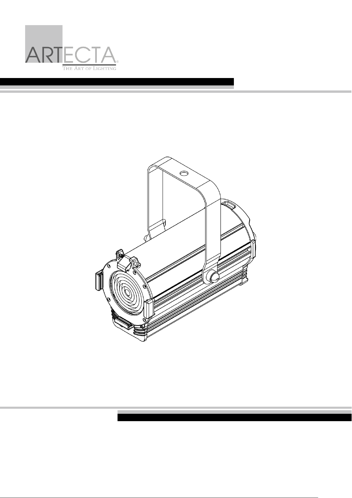
Display Fresnel 50 SW
Highlite International B.V. – Vestastraat 2 – 6468 EX – Kerkrade – the Netherlands
Product code: A0320110 – Black housing
A0320111 – White housing
USER MANUAL
ENGLISH
V1
Page 2

1
Display Fresnel 50 SW
Product code: A0320110 / A0320111
Preface
Thank you for purchasing this Artecta product.
The purpose of this user manual is to provide instructions for the correct and safe use of this product.
Keep the user manual for future reference as it is an integral part of the product. The user manual shall be
stored at an easily accessible location.
This user manual contains information concerning:
● Safety instructions
● Intended and non-intended use of the device
● Installation and operation of the device
● Maintenance procedures
● Troubleshooting
● Transport, storage and disposal of the device
Non-observance of the instructions in this user manual may result in serious injuries and damage of
property.
©2020 Artecta. All rights reserved.
No part of this document may be copied, published or otherwise reproduced without the prior written
consent of Highlite International.
Design and product specifications are subject to change without prior notice.
For the latest version of this document, please visit our website www.highlite.com or contact us at
Highlite International and its authorized service providers are not liable for any injury, damage, direct or
indirect loss, consequential or economic loss or any other loss arising from the use of, or inability to use or
reliance on the information contained in this document.
Page 3
2
Display Fresnel 50 SW
Product code: A0320110 / A0320111
Table of contents
1. Introduction .......................................................................................................................................................... 3
Before Using the Product .................................................................................................................................. 3
Intended Use ....................................................................................................................................................... 3
LEDs Lifespan ....................................................................................................................................................... 3
Text Conventions ................................................................................................................................................ 3
Symbols and Signal Words ................................................................................................................................ 4
Symbols on the Information Label .................................................................................................................. 4
2. Safety .................................................................................................................................................................... 4
Warnings and Safety Instructions .................................................................................................................... 4
Requirements for the User ................................................................................................................................. 6
3. Description of the Device ................................................................................................................................... 7
Front View ............................................................................................................................................................ 7
Back View ............................................................................................................................................................ 7
Barndoor .............................................................................................................................................................. 8
Color frame ......................................................................................................................................................... 8
Product Specifications ...................................................................................................................................... 9
Dimensions .........................................................................................................................................................10
4. Installation .......................................................................................................................................................... 10
Safety Instructions for Installation ..................................................................................................................10
Personal Protective Equipment .....................................................................................................................10
Installation Site Requirements ........................................................................................................................10
Mounting ............................................................................................................................................................11
Angle Adjustment ............................................................................................................................................12
Barndoor Installation ........................................................................................................................................12
Color Frame Installation ..................................................................................................................................13
Connecting to Power Supply .........................................................................................................................14
Power Linking of Multiple Devices .................................................................................................................14
5. Operation ........................................................................................................................................................... 15
Safety Instructions for Operation ...................................................................................................................15
Manual Control .................................................................................................................................................15
Beam Angle Adjustment ...........................................................................................................................15
6. Troubleshooting ................................................................................................................................................. 16
7. Maintenance ..................................................................................................................................................... 16
Safety Instructions for Maintenance .............................................................................................................16
Preventive Maintenance ................................................................................................................................16
Basic Cleaning Instructions .......................................................................................................................17
Corrective Maintenance ................................................................................................................................17
Replacing the Fuse .....................................................................................................................................17
8. Deinstallation, Transportation and Storage .................................................................................................... 18
Instructions for Deinstallation ..........................................................................................................................18
Instructions for Transportation ........................................................................................................................18
Storage ...............................................................................................................................................................18
9. Disposal .............................................................................................................................................................. 18
10. Approval ............................................................................................................................................................. 18
Page 4
3
Display Fresnel 50 SW
Product code: A0320110 / A0320111
1. Introduction
Before Using the Product
Important
Read and follow the instructions in this user manual before installing, operating or
servicing this product.
The manufacturer will not accept liability for any resulting damages caused by the non-observance of
this manual.
After unpacking, check the contents of the box. If any parts are missing or damaged, contact your
Highlite International dealer.
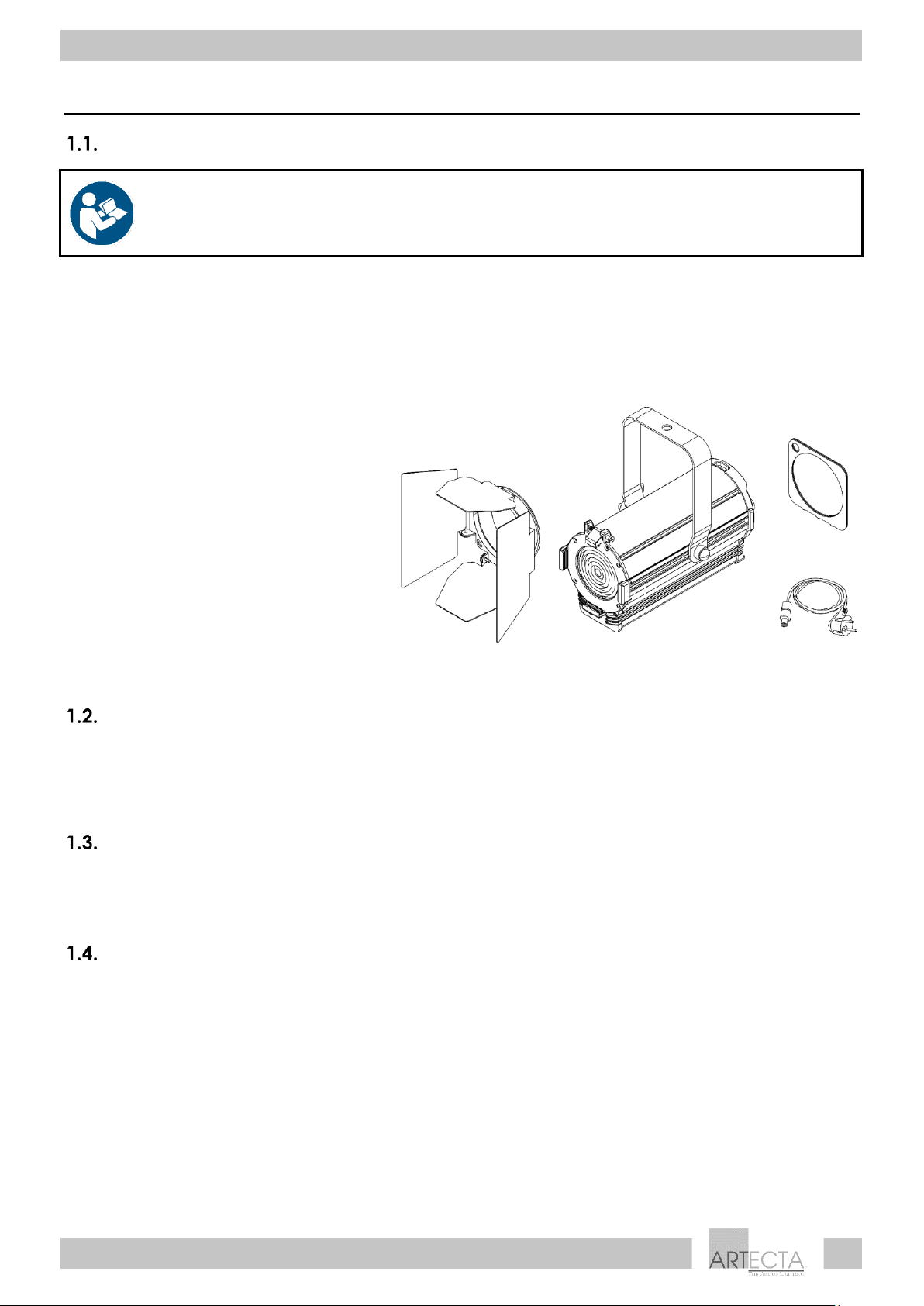
Your shipment includes:
● Artecta Display Fresnel 50 SW
● Schuko to pro-power cable (1,5 m)
● Barndoor
● Color frame
● User manual
Fig. 01
Intended Use
This device is intended for professional use as an architectural light spot. It is suitable for indoor installation
in shops, exhibition halls, showrooms and similar venues. This device is not suitable for households.
Any other use, not mentioned under intended use, is regarded as non-intended and incorrect use.
LEDs Lifespan
The light output of the LEDs gradually decreases over time (lumen depreciation). High operating
temperatures contribute to this process. You can extend the lifespan of the LEDs by providing adequate
ventilation and operating the LEDs at the lowest possible brightness.
Text Conventions
Throughout the user manual the following text conventions are used:
● References: References to chapters and parts of the device are in bold lettering, for example:
“Refer to 2. Safety”, “turn the adjustment handle (05)”
● 0–255: Defines a range of values
● Notes: Note: (in bold lettering) is followed by useful information or tips
Page 5
4
Display Fresnel 50 SW
Product code: A0320110 / A0320111
Symbols and Signal Words
Safety notes and warnings are indicated throughout the user manual by safety signs.
Always follow the instructions provided in this user manual.
DANGER
Indicates an imminently hazardous situation which, if not avoided, will result in
death or serious injury.
WARNING
Indicates a potentially hazardous situation which, if not avoided, could result in
death or serious injury.
CAUTION
Indicates a potentially hazardous situation, which, if not avoided, may result in
minor or moderate injury.
Attention
Indicates important information for the correct operation and use of the
product.
Important
Read and observe the instructions in this document.
Electrical hazard
Provides important information about the disposal of this product.
Symbols on the Information Label
This product is provided with an information label. The information label is located on the mounting
bracket.
The information label contains the following symbols:
This device is designed for indoor use.
This device falls under IEC protection class I.
This device shall not be treated as household waste.
2. Safety
Important
Read and follow the instructions in this user manual before installing, operating or
servicing this product.
The manufacturer will not accept liability for any resulting damages caused by the non-observance of
this manual.
Warnings and Safety Instructions
DANGER
Danger for children
Page 6
5
Display Fresnel 50 SW
Product code: A0320110 / A0320111
For adult use only. The device must be installed beyond the reach of children.
● Do not leave various parts of the packaging (plastic bags, polystyrene foam, nails, etc.) within
children’s reach. Packaging material is a potential source of danger for children.
DANGER
Electric shock caused by dangerous voltage inside
There are areas within the device where dangerous touch voltage may be present.
● Do not open the device or remove any covers.
● Do not operate the device if the covers or the housing is open. Before operation, check if the
housing is firmly closed and all screws are tightly fastened.
● Disconnect the device from electrical power supply before service and maintenance.
DANGER
Electric shock caused by short-circuit
This device falls under IEC protection class I.
● Make sure that the device is electrically connected to ground (earth). Connect the device only to a
socket-outlet with ground (earth) connection.
● Do not cover the ground (earth) connection.
● Do not bypass the thermostatic switch or fuses.
● For replacement use fuses of the same type and rating only.
● Do not let the power cable come into contact with other cables. Handle the power cable and all
connections with the mains with caution.
● Do not modify, bend, mechanically strain, put pressure on, pull or heat up the power cable.
● Make sure that the power cable is not crimped or damaged. Examine the power cable periodically
for any defects.
● Do not immerse the device in water or other liquids. Do not install the device in a location where
flooding may occur.
Attention
Power supply
● Before connecting the device to the power supply, make sure that the current, voltage and
frequency match the input voltage, current and frequency specified on the information label on the
device.
● Make sure that the cross-sectional area of the extension cords and power cables is sufficient for the
required power consumption of the device.
Attention
General safety
● Do not connect the device to a dimmer pack.
● Do not switch the device on and off in short intervals. This decreases the device’s life.
● Do not shake the device. Avoid brute force when installing or operating the device.
● Change the lens or the LEDs if they are visibly damaged to such an extent that their effectiveness is
impaired, for example by cracks or deep scratches. Contact your Highlite International dealer for
more information, as servicing can be performed only by instructed or skilled persons.
Page 7
6
Display Fresnel 50 SW
Product code: A0320110 / A0320111
● If the device is dropped or struck, disconnect the device from the electrical power supply
immediately.
● If the device fails to work properly, discontinue the use immediately.
Attention
For professional use only
This device shall be used only for the purposes it is designed for.
This device is intended for professional use as an architectural light spot. It is suitable for indoor installation
in shops, exhibition halls, showrooms and similar venues.
● This device is not suitable for households.
● This device does not contain user-serviceable parts. Unauthorized modifications to the device will
render the warranty void. Such modifications may result in injuries and material damage.
Attention
Before use, examine the device visually for any defects.
Make sure that:
● All screws used for installing the device or parts of the device are tightly fastened and are not
corroded.
● The safety devices are not damaged.
● There are no deformations on housings, fixations and installation points.
● The lens is not cracked or damaged.
● The power cables are not damaged and do not show any material fatigue.
Attention
Do not expose the device to conditions that exceed the rated IP class conditions.
This device is IP20 rated. IP (Ingress Protection) 20 class provides protection against solid objects greater
than 12 mm, such as fingers, and no protection against harmful ingress of water.
Requirements for the User
This product may be used by ordinary persons. Maintenance may be carried by ordinary persons.
Installation and service shall be carried out only by instructed or skilled persons. Contact your Highlite
dealer for more information.
Instructed persons have been instructed and trained by a skilled person, or are supervised by a skilled
person, for specific tasks and work activities associated with the installation, service and maintenance of
this product, so that they can identify risks and take precautions to avoid them.
Skilled persons have training or experience, which enables them to recognize risks and to avoid hazards
associated with the installation, service and maintenance of this product.
Ordinary persons are all persons other than instructed persons and skilled persons. Ordinary persons
include not only users of the product but also any other persons that may have access to the device or
who may be in the vicinity of the device.
Page 8
7
Display Fresnel 50 SW
Product code: A0320110 / A0320111
3. Description of the Device
The Artecta Display Fresnel 50 SW is a compact spot suitable for indoor venues, featuring two selectable
color temperatures: warm white and cold white. It has manual zooming and a built-in, manually
controllable dimmer (5 – 100 %). The device is delivered with a barndoor and a color frame.
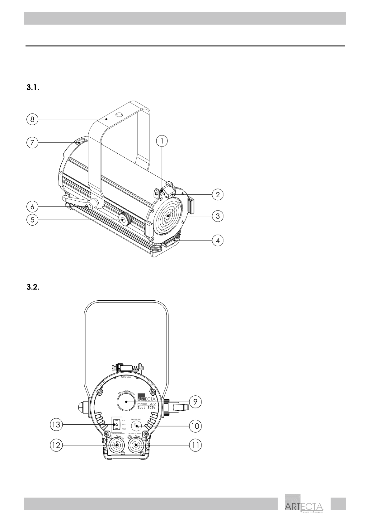
Front View
01) Spring-loaded screw
02) Color frame clip
03) Fresnel lens
04) 3 x Color frame holders
05) Zoom control
06) Adjustment handle
07) Safety eye
08) Mounting bracket
Fig. 02
Back View
09) Manual dimmer control
10) Fuse F1 AL/250 V AC
11) Pro-power connector OUT 100–
240 V, 50/60 Hz (Gray)
12) Pro-power connector IN 100–240 V,
50/60 Hz (Blue)
13) Color temperature switch (CW,
OFF, WW)
Fig. 03
Page 9
8
Display Fresnel 50 SW
Product code: A0320110 / A0320111
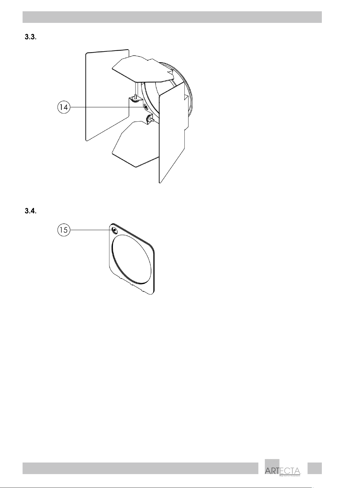
Barndoor
14) Safety eye (barndoor)
Fig. 04
Color frame
15) Safety eye (color frame)
Fig. 05
Page 10
9
Display Fresnel 50 SW
Product code: A0320110 / A0320111
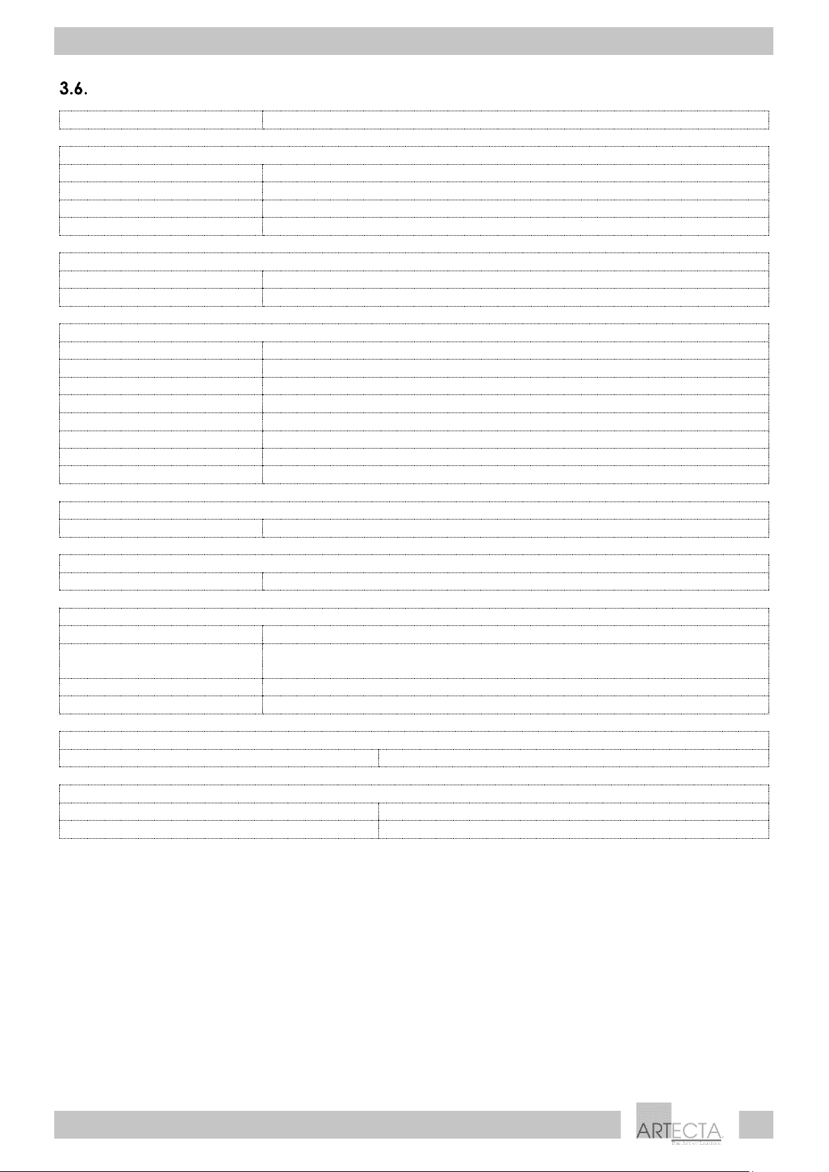
Product Specifications
Model:
Display Fresnel 50 SW
Electrical:
Input voltage:
100–240 V AC, 50/60 Hz
Power consumption:
55 W
PFC:
0,93
Fuse:
T1 AL, 250 V
Physical:
Dimensions:
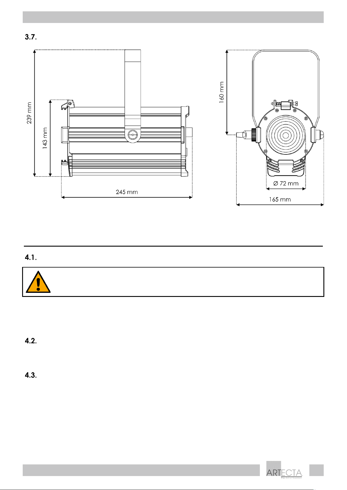
245 x 165 x 239 mm (L x W x H) (without accessories)
Weight:
1,8 kg
Optics:
Light source:
50 W Dual Color COB LED
Dimmer:
5–100 %
Zoom:
Manual
Beam angle:
18°–58°
Color temperature:
3000 K and 6000 K (selectable)
Output:
3000 K – 1123 lm (18°); 2595 lm (58°)
6000 K – 1459 lm (18°); 3373 lm (58°)
CRI:
>95
Operation and control:
Control:
Manual
Connections:
Power connection:
Pro-power connectors IN/OUT 100–240 V, 50/60 Hz
Construction:
Housing:
Extruded aluminum
Color:
Black (product code: A0320110)
White (product code: A0320111)
IP rating:
IP20
Cooling:
Natural convection
Thermal:
Maximum ambient temperature ta:
40 °C
Minimum distance:
Minimum distance from flammable surfaces:
0,5 m
Minimum distance to lighted object:
0,5 m
Page 11
10
Display Fresnel 50 SW
Product code: A0320110 / A0320111
Dimensions
Fig. 06
4. Installation
Safety Instructions for Installation
WARNING
Incorrect installation can cause serious injuries and damage of property.
If the device is installed overhead, the installation must be carried out only by instructed or skilled persons.
Follow all applicable European, national and local safety regulations concerning overhead installation
on supporting structures.
Personal Protective Equipment
During installation and mounting wear personal protective equipment in compliance with the national
and site-specific regulations.
Installation Site Requirements
● The device can be used only indoors.
● The device can be mounted to a supporting structure in any orientation.
● The minimum distance to other objects must be bigger than 0,5 m.
● The maximum ambient temperature t
a
= 40 °C must never be exceeded.
● The relative humidity must not exceed 50 % with an ambient temperature of 40 °C.
Page 12
11
Display Fresnel 50 SW
Product code: A0320110 / A0320111
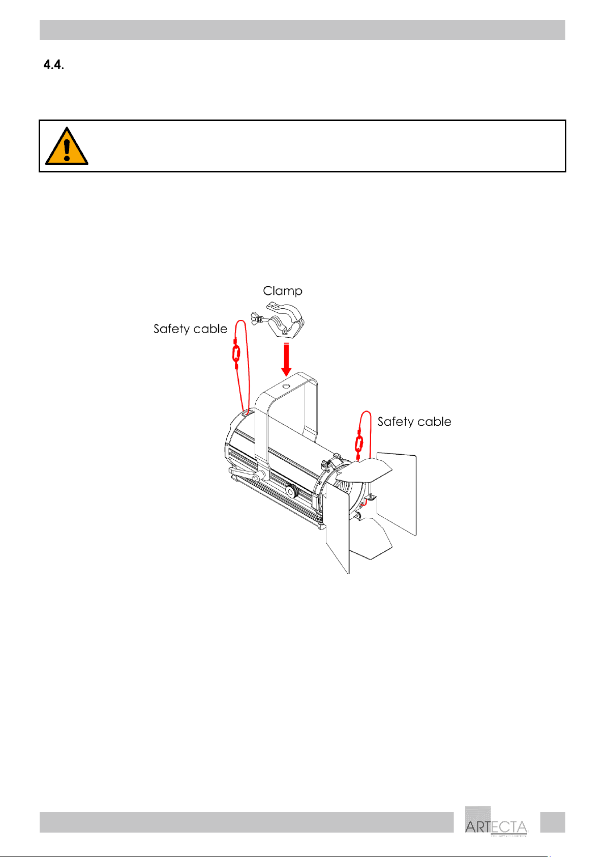
Mounting
The device can be mounted to a supporting structure in any orientation. Make sure that all loads are
within the pre-determined limits of the supporting structure.
CAUTION
Restrict the access under the work area during mounting.
To mount the device, follow the steps below:
01) Use a clamp to attach the device to the supporting structure, as shown in Fig. 07. Make sure that the
device cannot move freely.
02) Secure the device with a secondary suspension, for example a safety cable. Make sure that the
secondary suspension can hold 10 times the weight of the device. If possible, the secondary
suspension should be attached to a supporting structure independent of the primary suspension. Put
the safety cable through the safety eye (07), as shown in Fig. 07.
Fig. 07
Page 13
12
Display Fresnel 50 SW
Product code: A0320110 / A0320111
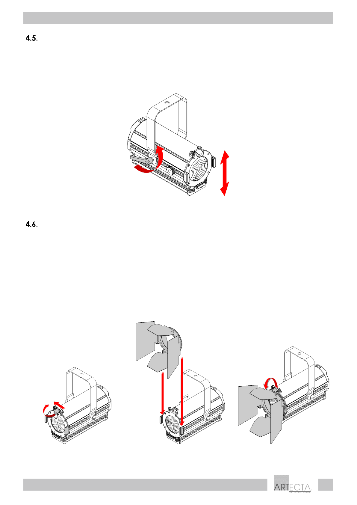
Angle Adjustment
You can adjust the angle of the device with the adjustment handle (06).
01) Turn the adjustment handle (06) counterclockwise to release it.
02) Tilt the device at the desired angle (see Fig. 08).
03) Turn the adjustment handle (06) clockwise to tighten it. Make sure that the device cannot move
freely after the adjustment handle (06) is tightened.
Fig. 08
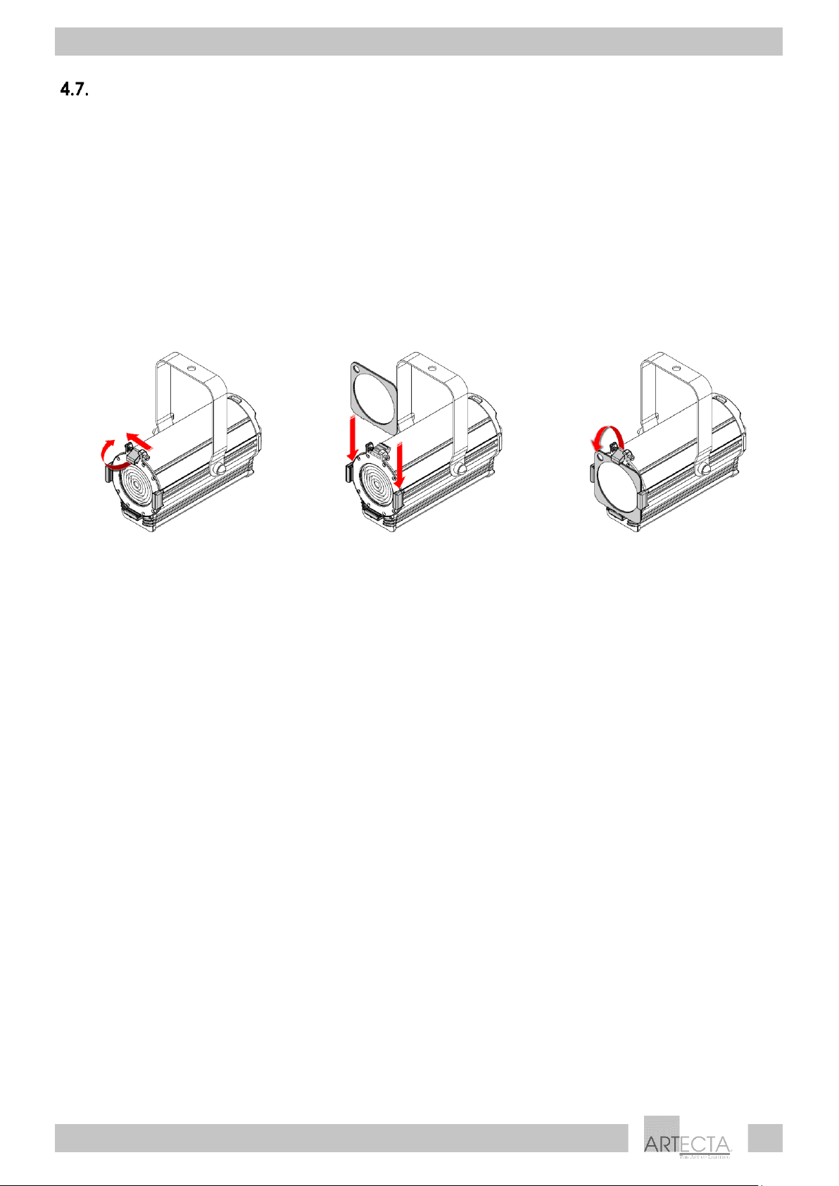
Barndoor Installation
The Display Fresnel 50 SW is delivered with a barndoor. To install the barndoor, follow the steps below:
01) Push the spring-loaded screw (01) and at the same time lift and flip backwards the color frame clip
(02) (see Fig. 09).
02) Insert the barndoor into the color frame holders (04) (see Fig. 10).
03) Pull the color frame clip (02) downwards to release the spring-loaded screw (01) (see Fig. 11). The
barndoor will be locked in position.
04) Secure the barndoor to the overhead structure with an appropriate secondary attachment, for
example a safety cable. See 4.4. Mounting on page 11.
Make sure that the barndoor is locked in position with the color frame clip before using the device.
Fig. 09
Fig. 10
Fig. 11
Page 14
13
Display Fresnel 50 SW
Product code: A0320110 / A0320111
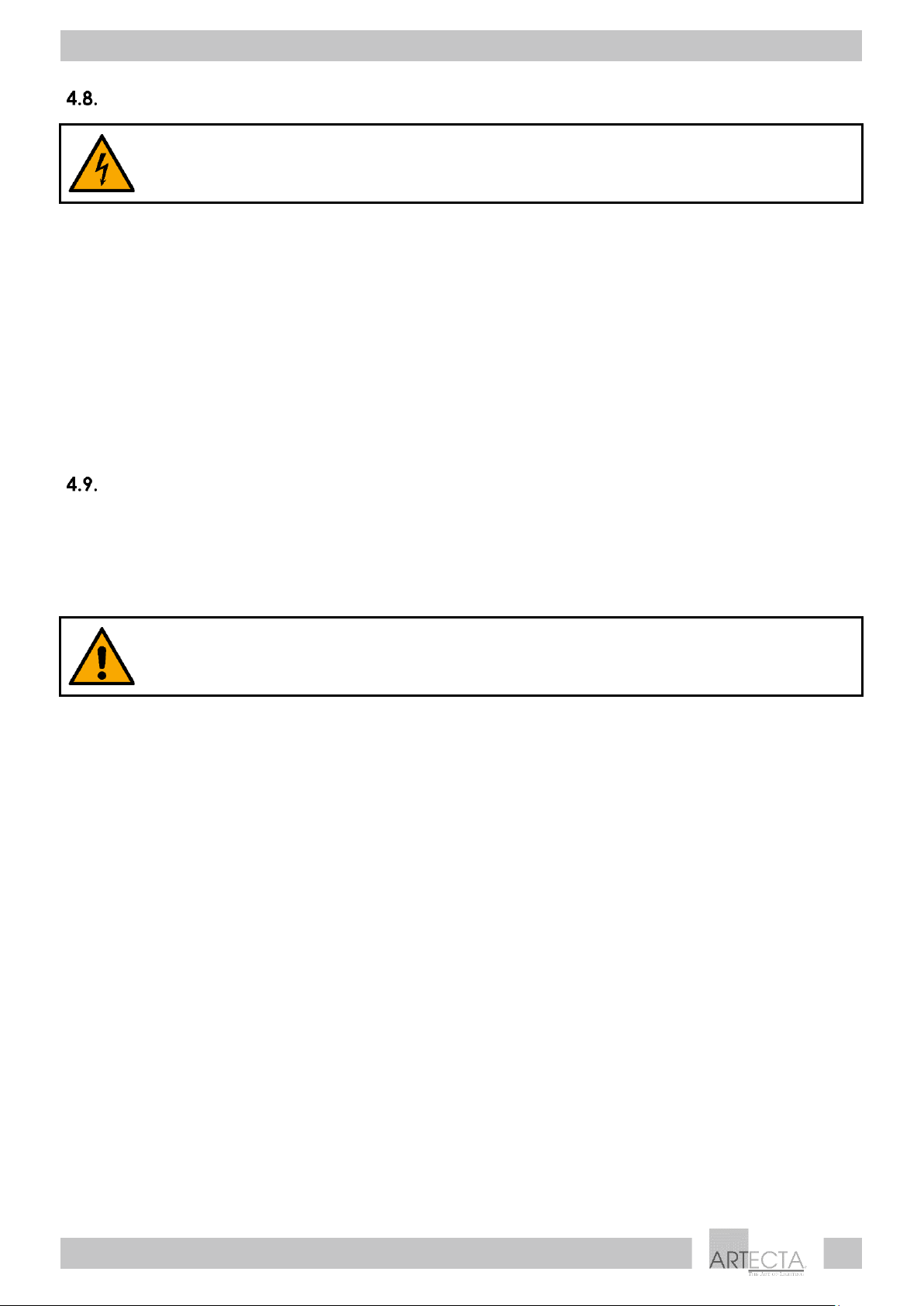
Color Frame Installation
The Display Fresnel 50 SW is delivered with a color frame. You can insert a color gel or a diffusion filter into
the color frame. To install the color frame, follow the steps below:
01) Push the spring-loaded screw (01) and at the same time lift and flip backwards the color frame clip
(02) (see Fig. 12).
02) Insert a color gel or a diffusion filter into the color frame.
03) Insert the color frame into the color frame holders (04) (see Fig. 13).
04) Pull the color frame clip (02) downwards to release the spring-loaded screw (01) (see Fig. 14). The
color frame will be locked in position.
05) Secure the color frame to the trussing with an appropriate secondary attachment, for example a
safety cable. See 4.4. Mounting on page 11.
Make sure that the color frame is locked in position with the color frame clip before using the device.
Fig. 12
Fig. 13
Fig. 14
Page 15
14
Display Fresnel 50 SW
Product code: A0320110 / A0320111
Connecting to Power Supply
DANGER
Electric shock caused by short-circuit
The device accepts AC mains power at 100–240 V and 50/60 Hz. Do not supply power at any other
voltage or frequency to the device.
This device falls under IEC protection class I. Make sure that the device is always electrically connected
to the ground (earth).
Before connecting the device to the socket-outlet:
● Make sure that the power supply matches the input voltage specified on the information label on
the device.
● Make sure that the socket-outlet has ground (earth) connection.
Connect the device to the socket-outlet with the power plug. Do not connect the device to a dimmer
circuit, as this may damage the device.
Power Linking of Multiple Devices
This device supports power linking. Power can be relayed to another device via the power OUT
connector. Note that the input and the output connectors have different designs: one type cannot be
connected to the other.
Power linking of multiple devices must be carried out only by instructed or skilled persons.
WARNING
Incorrect power linking may lead to overload of the electrical circuit and result in serious
injuries and damage of property.
To prevent overload of the electrical circuit, when power linking multiple devices:
● Use cables with sufficient current-carrying capacity. The power cable supplied with the device is not
suitable for power linking of multiple devices.
● Make sure that the total current draw of the device and all connected devices does not exceed the
rated capacity of the power cables and the circuit breaker.
● Do not link more devices on one power link than the maximum recommended number.
Maximum recommended number of devices:
● at 100–120 V: 10 devices Display Fresnel 50 SW
● at 200–240 V: 20 devices Display Fresnel 50 SW
Page 16
15
Display Fresnel 50 SW
Product code: A0320110 / A0320111
5. Operation
Safety Instructions for Operation
Attention
This device must be used only for the purposes it is designed for.
This device is intended for professional use as an architectural light spot. It is suitable for indoor installation
in shops, exhibition halls, showrooms and similar venues. This device is not suitable for households.
Any other use, not mentioned under intended use, is regarded as non-intended and incorrect use.
Attention
Power supply
Before connecting the device to the power supply, make sure that the current, voltage and frequency
match the input voltage, current and frequency specified on the information label on the device.
Manual Control
The Display Fresnel 50 SW can be operated only manually. The device is equipped with a color
temperature switch and a manual dimmer control.
● Set the color temperature switch (13) to CW or WW position to turn the device on.
● CW (cold white) position – the light will turn on with a predefined color temperature of 6000 K
● WW (warm white) position – the light will turn on with a predefined color temperature of 3000 K
● Turn the manual dimmer control (09) to adjust the light intensity. The adjustment range is 5–100 %.
● Set the color temperature switch (13) to OFF position to turn the device off.
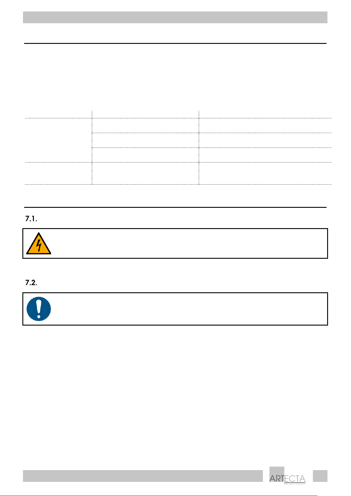
Beam Angle Adjustment
The beam angle of the Display Fresnel 50 SW can be adjusted manually in the range 18°–58°. To adjust
the beam angle, follow the steps below:
01) Turn the zoom control (05) counterclockwise to loosen it.
02) Slide the zoom control (05) forwards or backwards to achieve the desired beam angle (see Fig. 15).
03) After adjusting the beam angle, turn the zoom control (05) clockwise to tighten it. Do not
overtighten it.
Fig. 15
Page 17
16
Display Fresnel 50 SW
Product code: A0320110 / A0320111
6. Troubleshooting
This troubleshooting guide contains solutions to problems which can be carried out by an ordinary
person. The device does not contain user-serviceable parts.
Unauthorized modifications to the device will render the warranty void. Such modifications may result in
injuries and material damage.
Refer servicing to instructed or skilled persons. Contact your Highlite International dealer in case the
solution is not described in the table.
Problem
Probable cause(s)
Solution
The device does not
function
No power to the device
● Check if power is switched on and
cables are plugged in
Main fuse is blown
● Replace the fuse. See 7.3.1. Replacing
the Fuse on page 17
LEDs are damaged
● Disconnect the device and contact
your Highlite International dealer
No light or LEDs cut
out intermittently
The power supply settings do not
match local AC voltage and
frequency
● Disconnect the device. Check the
settings and correct, if necessary
7. Maintenance
Safety Instructions for Maintenance
DANGER
Electric shock caused by dangerous voltage inside
Disconnect power supply before servicing or cleaning.
Preventive Maintenance
Attention
Before use, examine the device visually for any defects.
Make sure that:
● All screws used for installing the device or parts of the device are tightly fastened and are not
corroded.
● The safety devices are not damaged.
● There are no deformations on housings, fixations and installation points.
● The lens is not cracked or damaged.
● The power cables are not damaged and do not show any material fatigue.
Page 18
17
Display Fresnel 50 SW
Product code: A0320110 / A0320111
Basic Cleaning Instructions
The external lens of the device must be cleaned periodically in order to optimize the light output. The
cleaning schedule depends on the conditions at the site where the device is installed. When smoke or
fog machines are used at the site, the device will need more frequent cleaning. On the other hand, if the
device is installed in a well-ventilated area, it will need less frequent cleaning. To establish a cleaning
schedule, examine the device at regular intervals during the first 100 hours of operation.
To clean the device, follow the steps below:
Disconnect the device from the electrical power supply.
Allow the device to cool down for at least 15 minutes.
03) Remove the dust collected on the external surface with dry compressed air and a soft brush.
04) Clean the lens with a damp cloth. Use a mild detergent solution.
05) Dry the lens carefully with a lint-free cloth.
06) Clean the connections with a damp cloth.
Attention
● Do not immerse the device in liquid.
● Do not use alcohol or solvents.
● Make sure that the connections are fully dry before connecting the device to the power supply.
Corrective Maintenance
The device does not contain user-serviceable parts. Do not open the device and do not modify the
device.
Refer repairs and servicing to instructed or skilled persons. Contact your Highlite International dealer for
more information.
Replacing the Fuse
DANGER
Electric shock caused by short-circuit
● Do not bypass the thermostatic switch or fuses.
● For replacement use fuses of the same type and rating only.
Power surges, short-circuit or incorrect electrical power supply may cause a fuse to burn out. If the fuse
burns out, the device will not function anymore. If this happens, follow the steps below:
01) Disconnect the device from the electrical power supply.
01) Allow the device to cool down for at least 15 minutes.
02) Loosen the fuse cover with a screwdriver and remove the fuse holder.
03) If the fuse is brown or unclear, it is burned out. Remove the old fuse.
04) Insert a new fuse in the fuse holder. Make sure that the type and the rating of the replacement fuse
are the same as the ones specified on the information label of the product.
05) Replace the fuse holder in the opening and tighten the fuse cover.
Page 19
18
Display Fresnel 50 SW
Product code: A0320110 / A0320111
8. Deinstallation, Transportation and Storage
Instructions for Deinstallation
WARNING
Incorrect deinstallation can cause serious injuries and damage of property.
● Let the device cool down before dismounting.
● Disconnect power supply before deinstallation.
● Always observe the national and site-specific regulations during deinstallation and dismounting of
the device.
● Wear personal protective equipment in compliance with the national and site-specific regulations.
Instructions for Transportation
● Use the original packaging to transport the device, if possible.
● Always observe the handling instructions printed on the outer carton box, for example: “Handle with
care”, “This side up”, “Fragile”.
Storage
● Clean the device before storing. Follow the cleaning instructions in chapter 7.2.1. Basic Cleaning
Instructions on page 17.
● Store the device in the original packaging, if possible.
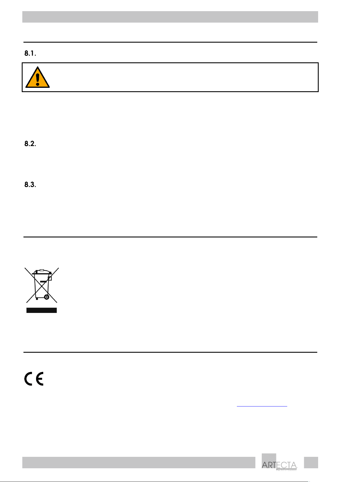
9. Disposal
Correct disposal of this product
Waste Electrical and Electronic Equipment
This symbol on the product, its packaging or documents indicates that the product
shall not be treated as household waste. Dispose of this product by handing it to the
respective collection point for recycling of electrical and electronic equipment. This is
to avoid environmental damage or personal injury due to uncontrolled waste
disposal. For more detailed information about recycling of this product contact the
local authorities or the authorized dealer.
10. Approval
Check the respective product page on the website of Highlite International (www.highlite.com) for an
available declaration of conformity.
Page 20

©2020 Artecta
 Loading...