

Page 1
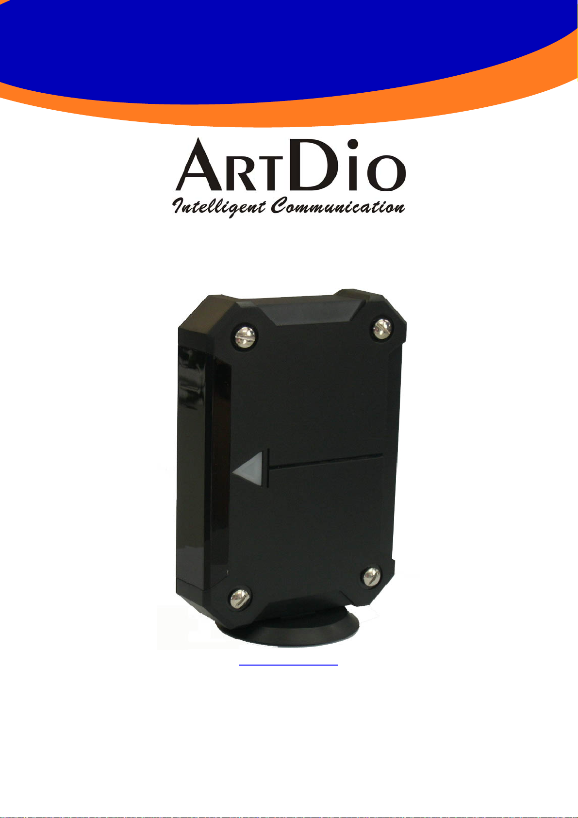
IPS-2000 Series User’s manual/使用手冊
V1.1
www.artdio.com.tw
Page 2

IPS-2000 Series User’s Manual/使用手冊
Safety Instructions
˙Do not attempt to service the product yourself. Any servicing of this
product should be referred to qualified service personnel.
˙To avoid electrical shock, do not put your finger, pin, wire, or any other
metal objects into vents and gaps.
˙To avoid accidental fire or electrical shock, do not twist power cord or
place it under heavy objects.
˙The product should be connected to a power supply of the type described
in the operating instructions or as marked on the product.
˙To avoid hazard to children, dispose of the product’s plastic packaging
carefully.
˙Please read all the instructions before using this product.
2
Page 3

IPS-2000 Series User’s Manual/使用手冊
contents
1. PRODUCT INTRODUCTION.............................................................................................................................................7
2. QUICK INSTALLATION GUIDE.......................................................................................................................................8
2.1 INTERFACE DESCRIPTION (SUITABLE FOR IPS-2000 PLUS).................................................................................................8
2.2 INTERFACE DESCRIPTION (SUITABLE FOR IPS-2000NPLUS) ..............................................................................................9
2.3 NETWORK INSTALLATION AND SETTING..........................................................................................................................10
2.4 SYSTEM REGISTRATION AND LOG ON ...............................................................................................................................13
2.4.1 Status LED Indicator Explanation (suitable for IPS-2000 Plus).............................................................................13
2.4.2 Status LED Indicator Explanation (suitable for IPS-2000NPlus)........................................................................... 13
2.4.3 Quick Startup and Registration Guide ....................................................................................................................13
2.5 IVR INTERFACE FOR IPS-2000 SERIES.............................................................................................................................15
2.6 INBOUND FUNCTION ........................................................................................................................................................ 16
3. WEB CONFIGURATION PAGE.......................................................................................................................................18
3.1 INFORMATION ..................................................................................................................................................................18
3.2 PHONE SETTING ...............................................................................................................................................................18
3.2.1 Caller ID .................................................................................................................................................................18
3.2.2 Phone Book .............................................................................................................................................................19
3.2.3 Auto Answer ..................................................................................... ................... ....................................................19
3.2.4 Dial Plan Setting.....................................................................................................................................................20
3.2.5 Forward Setting.......................................................................................................................................................21
3.2.6 Call Waiting.............................................................................................................................................................22
3.2.7 DND Setting ............................................................................................................................................................22
3.2.8 Volume Setting.........................................................................................................................................................23
3.2.9 Flash Time Setting...................................................................................................................................................23
3.2.10 T.38 (FAX) Setting .................................................................................................................................................24
3.2.11 VoIP/PSTN Switch Setting .....................................................................................................................................24
3.3 NETWORKING...................................................................................................................................................................24
3.3.1 Status.......................................................................................................................................................................24
3.3.2 Network Setting.......................................................................................................................................................25
3.3.3 DDNS Setting..........................................................................................................................................................26
3.3.4 VLAN Setting...........................................................................................................................................................27
3.3.5 SNTP Setting ...........................................................................................................................................................28
3.4 NAT ROUTER...................................................................................................................................................................28
3.4.1 NAT Setting..............................................................................................................................................................29
3.4.2 DMZ Setting ............................................................................................................................................................29
3.5 SIP SETTING.....................................................................................................................................................................30
3.5.1 Service Domain.......................................................................................................................................................30
3.5.2 Port Setting..............................................................................................................................................................31
3.5.3 Codec Setting...........................................................................................................................................................32
3.5.4 Codec ID .................................................................................................................................................................33
3.5.5 DTMF Setting..........................................................................................................................................................33
3.5.6 STUN Setting...........................................................................................................................................................33
3.5.7 RPort Setting...........................................................................................................................................................34
3.5.8 Other Setting ...........................................................................................................................................................34
3.6 OTHERS............................................................................................................................................................................35
3.6.1 Auto Config .............................................................................................................................................................35
3.6.2 Firmware upgrade...................................................................................................................................................35
3.6.3 Auto update .............................................................................................................................................................36
3.6.4 Default Setting.........................................................................................................................................................38
3.6.5 Advanced Setting.....................................................................................................................................................38
3.6.6 FXO & FXS port ..................................................................................................................................................... 39
3
Page 4

IPS-2000 Series User’s Manual/使用手冊
3.6.7 System Auth.............................................................................................................................................................39
3.7 SAVE CHANGE..................................................................................................................................................................40
3.8 REBOOT ...........................................................................................................................................................................40
4. PRODUCT SPECIFICATIONS.........................................................................................................................................41
5. FREQUENTLY ASKED QUESTIONS (FAQ)..................................................................................................................42
4
Page 5

IPS-2000 Series User’s Manual/使用手冊
目 錄
1. 產品介紹 ..............................................................................................................................................................................47
1.1 包裝內容........................................................................................................................................................................47
1.2 產品特性........................................................................................................................................................................47
1.3 產品示意圖....................................................................................................................................................................48
2. 快速安裝 ..............................................................................................................................................................................49
2.1 介面說明(適合 IPS-2000 PLUS)...............................................................................................................................49
2.2 介面說明(適合 IPS-2000N PLUS)............................................................................................................................50
2.3 設備安裝........................................................................................................................................................................51
2.4 註冊登入.........................................................................................................................................................................53
2.4.1 STATUS
2.4.2 STATUS
2.4.3
2.5 電話機狀態設定.............................................................................................................................................................56
2.6 IPS-2000 SERIES 的上下車功能.....................................................................................................................................56
2.7 IPS-2000 SERIES 上下車的操作步驟.............................................................................................................................57
3. 網頁設定 ..............................................................................................................................................................................58
3.1 INFORMATION(系統資訊)...........................................................................................................................................58
3.2 PHONE SETTING(話機設定) .......................................................................................................................................58
3.2.1 Caller ID .................................................................................................................................................................58
3.2.2 Phone Book
3.2.3 Auto Answer
3.2.4 Dial Plan Setting
3.2.5 Forward Setting
3.2.6 Call Waiting
3.2.7 DNS Setting
3.2.8 Volume Setting
3.2.9 Flash Time Setting
3.2.10 T.38 (FAX) Setting
3.2.11 VoIP/PSTN Switch Setting(VoIP/PSTN
3.3 NETWORKING(網路)...................................................................................................................................................65
3.3.1 Status
3.3.2 Network Setting
3.3.3 DDNS Setting..........................................................................................................................................................67
3.3.4 VLAN Setting...........................................................................................................................................................68
3.3.5 SNTP Setting ...........................................................................................................................................................69
3.4 NAT ROUTER(NAT 路由器設定) ..............................................................................................................................70
3.4.1 NAT Setting..............................................................................................................................................................70
3.4.2 DMZ Setting ............................................................................................................................................................71
3.5 SIP SETTING(SIP 設定) ..............................................................................................................................................71
3.5.1 Service Domain
3.5.2 Port Setting
3.5.3 Codec Setting
3.5.4 Codec ID .................................................................................................................................................................73
3.5.5 DTMF Setting..........................................................................................................................................................74
3.5.6 STUN Setting...........................................................................................................................................................74
(狀態指示)燈號說明(適合
(狀態指示)燈號說明(適合
快速啟動註冊說明
(電話簿)
(自動應答)
(撥號規則)
(電話轉接)
(來電等待)
(來電拒接)
(音量設定)
(閃切設定)
(網路狀態)
(網路設定)
(平台設定)
(埠號設定)
(語音編解碼設定)
IPS-2000 Plus).........................................................................................53
IPS-2000N Plus) ......................................................................................54
................................................................................................................................................54
..........................................................................................................................................59
...................................................................................................................................60
.............................................................................................................................61
............................................................................................................................... 62
.....................................................................................................................................62
.....................................................................................................................................63
.................................................................................................................................64
...........................................................................................................................64
(傳真設定)
...............................................................................................................................................65
..........................................................................................................................65
切換功能鍵設定)
............................................................................................................................... 66
............................................................................................................................... 71
......................................................................................................................................72
.......................................................................................................................73
...............................................................................65
5
Page 6

IPS-2000 Series User’s Manual/使用手冊
3.5.7 RPort Setting...........................................................................................................................................................75
3.5.8 Other Setting ...........................................................................................................................................................75
3.6 OTHERS(其他設定)....................................................................................................................................................76
3.6.1 Auto Config
3.6.2 Firmware upgrade
5.6. 3 Auto Update
3.6.4 Default Setting
3.6.5 Advanced Setting
3.6.6 FXO & FXS port(FXO/FXS
3.6.7 System Auth.............................................................................................................................................................80
3.7 SAVE CHANGE(儲存設定)..........................................................................................................................................81
3.8 REBOOT(重新啟動)....................................................................................................................................................81
4. 產品規格 ..............................................................................................................................................................................82
5. 常見問題與排解(Q&A).................................................................................................................................................83
(自動設定)
(韌體升級)
(自動升級韌體)
(回復出廠設定值)
(進階設定)
......................................................................................................................................76
...........................................................................................................................77
............................................................................................................................77
.....................................................................................................................79
.............................................................................................................................79
設定)
.....................................................................................................................80
6
Page 7
IPS-2000 Series User’s Manual/使用手冊
1. Product Introduction
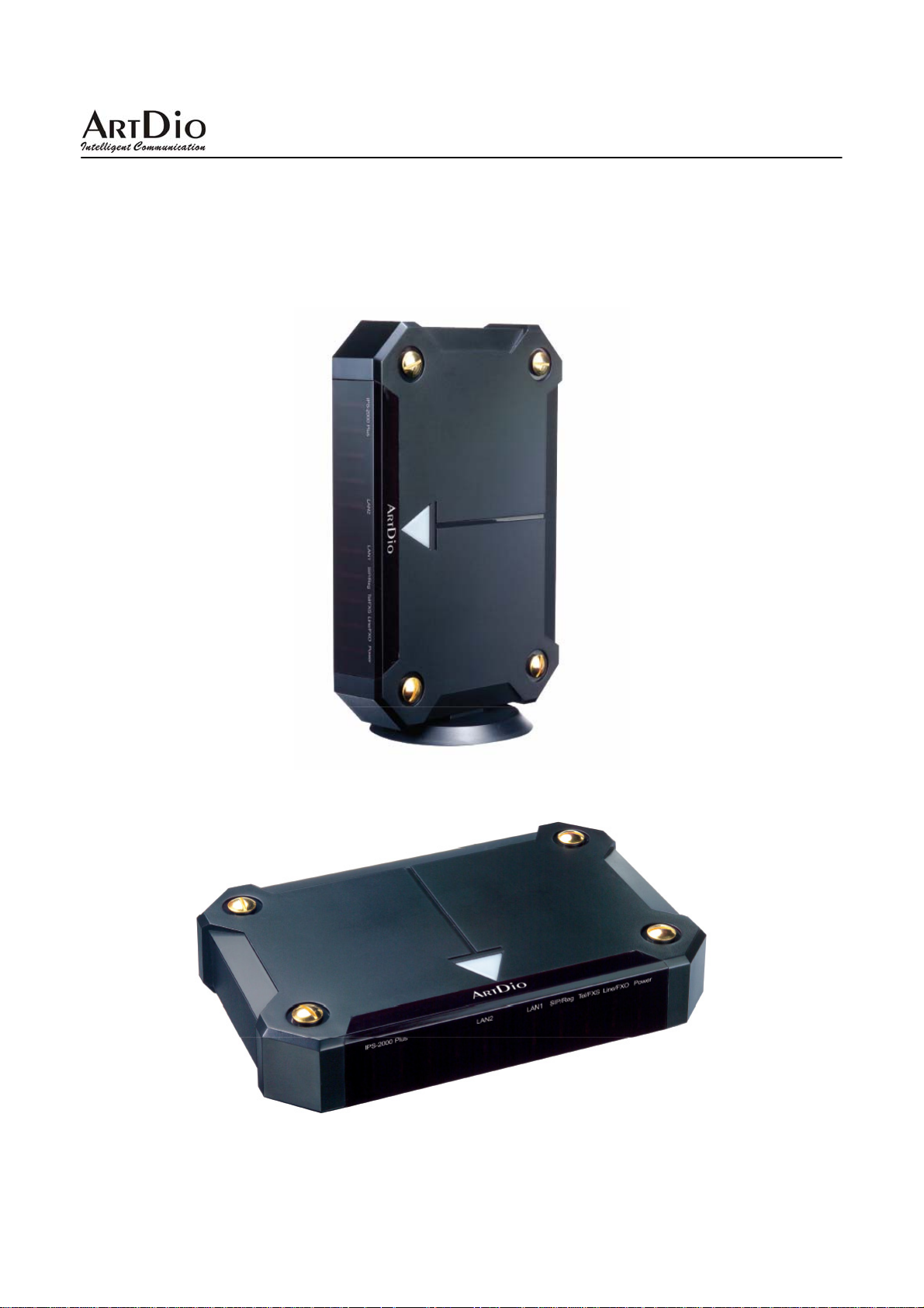
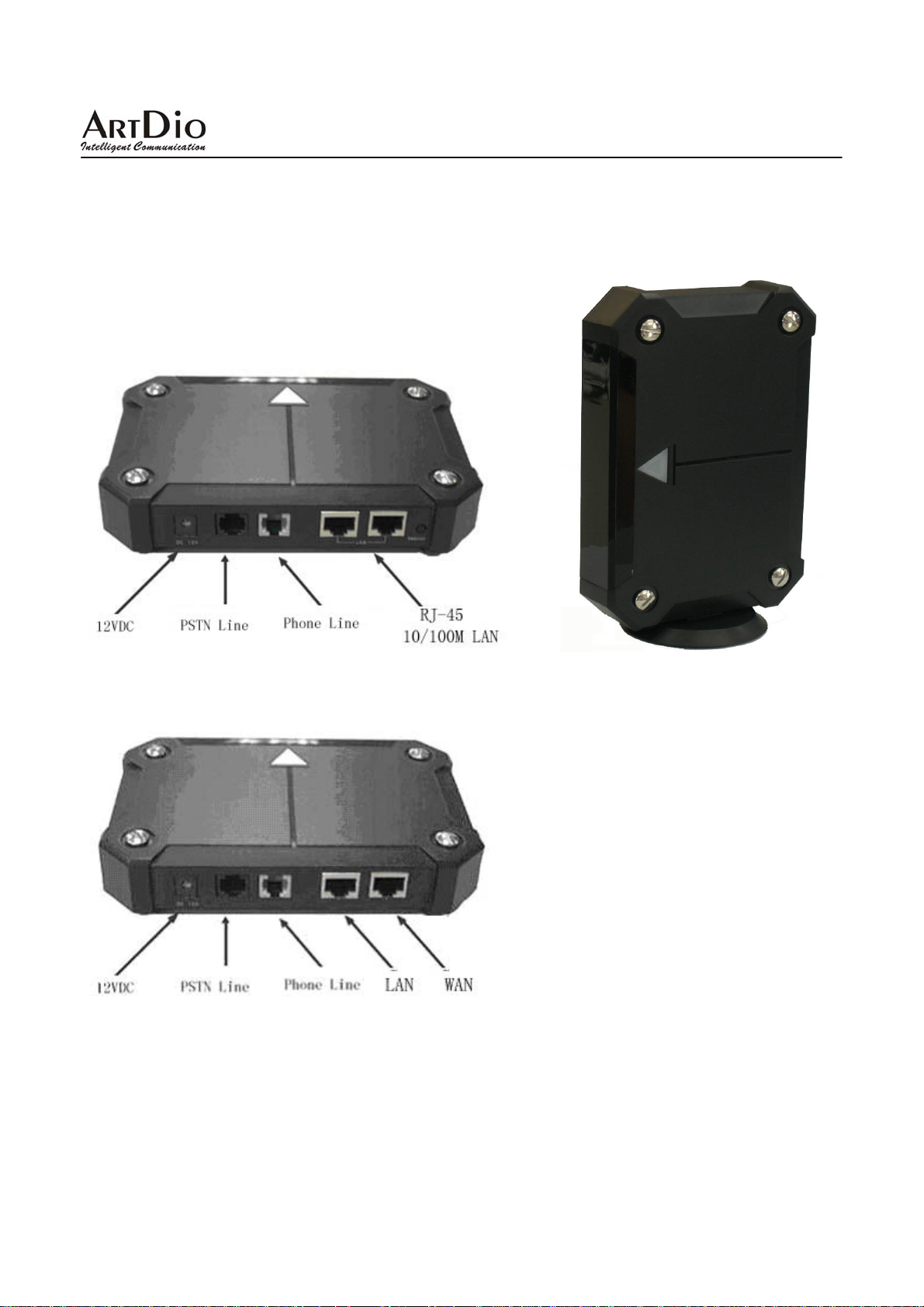
The product is designed for flexibility to be placed flat or vertically, to customize the different needs of users.
Vertical Panel Image
Flat Panel Image
7
Page 8
IPS-2000 Series User’s Manual/使用手冊
2. Quick Installation Guide
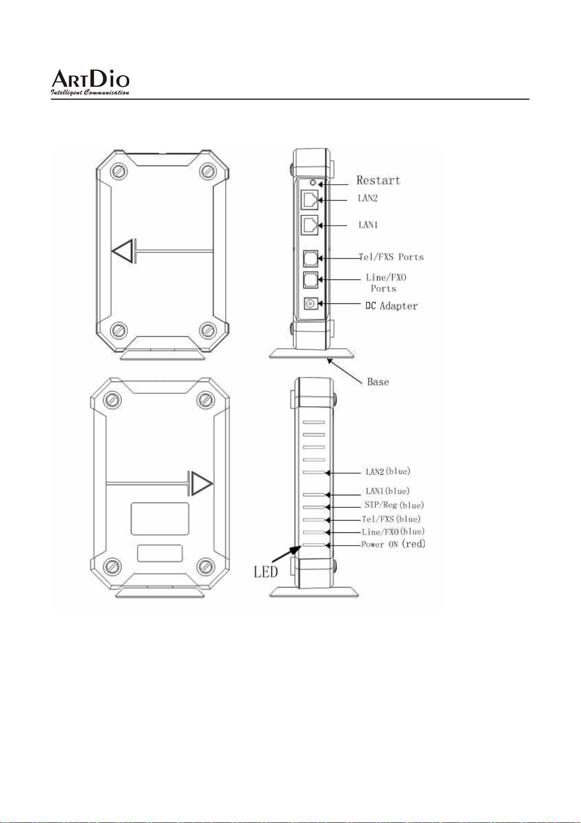
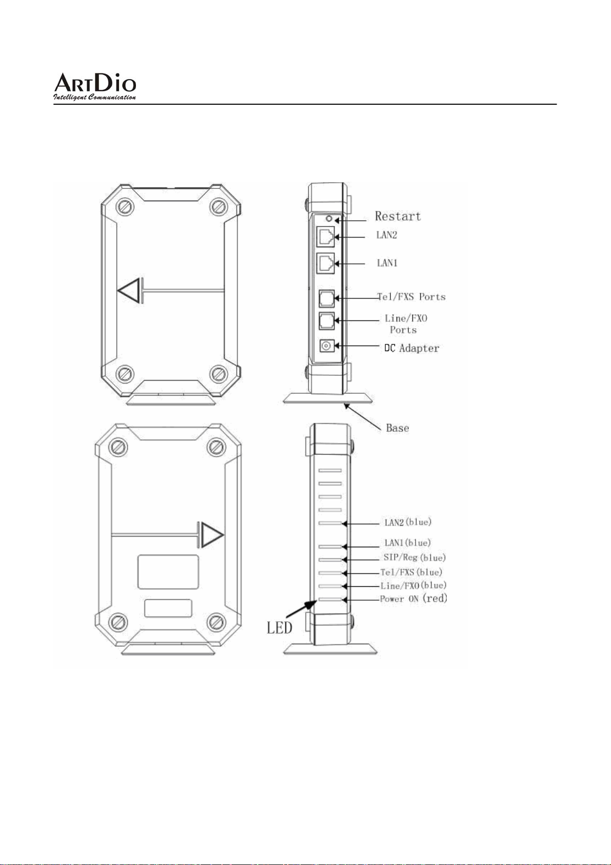
2.1 Interface Description (suitable for IPS-2000 Plus)
8
Page 9
IPS-2000 Series User’s Manual/使用手冊
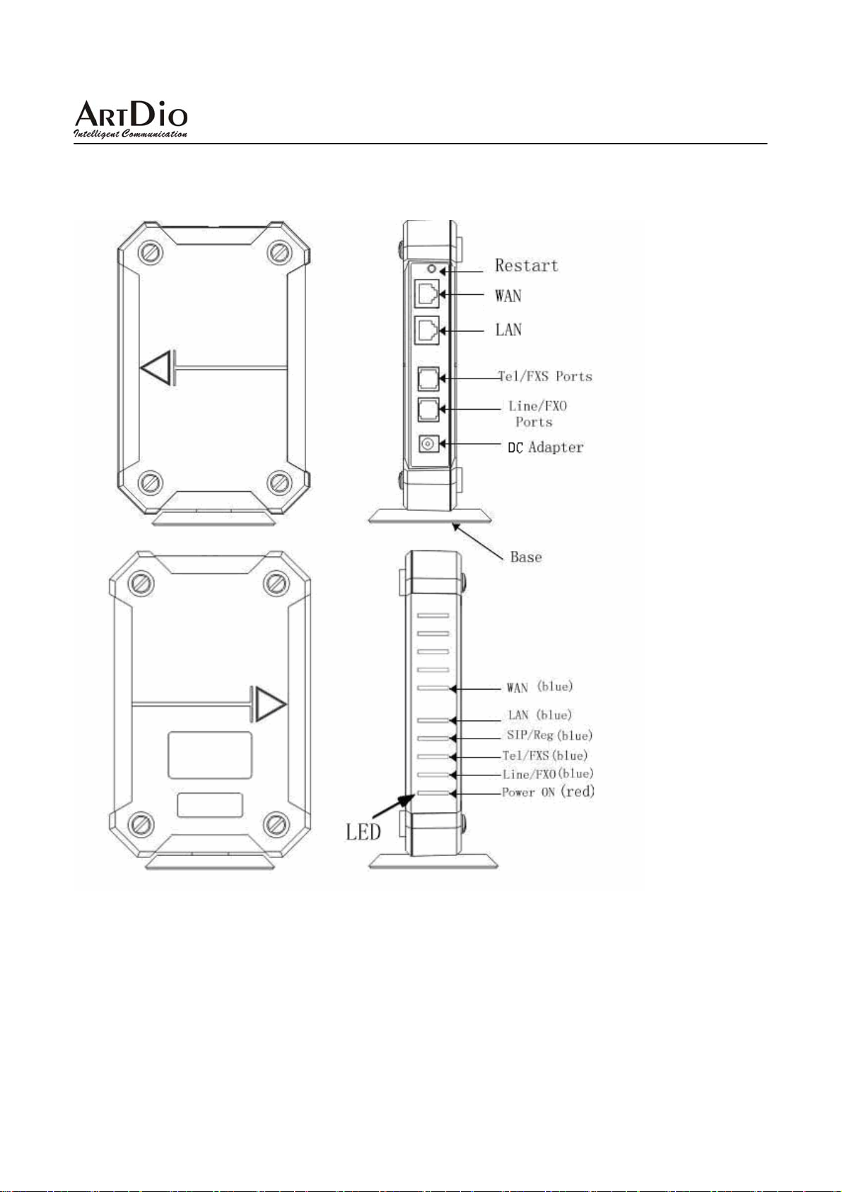
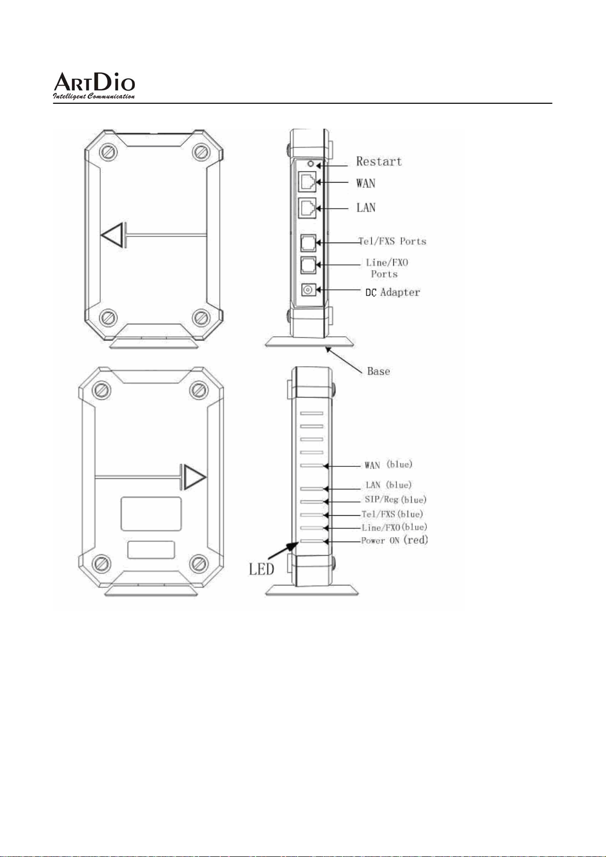
2.2 Interface Description (suitable for IPS-2000NPlus)
9
Page 10
IPS-2000 Series User’s Manual/使用手冊
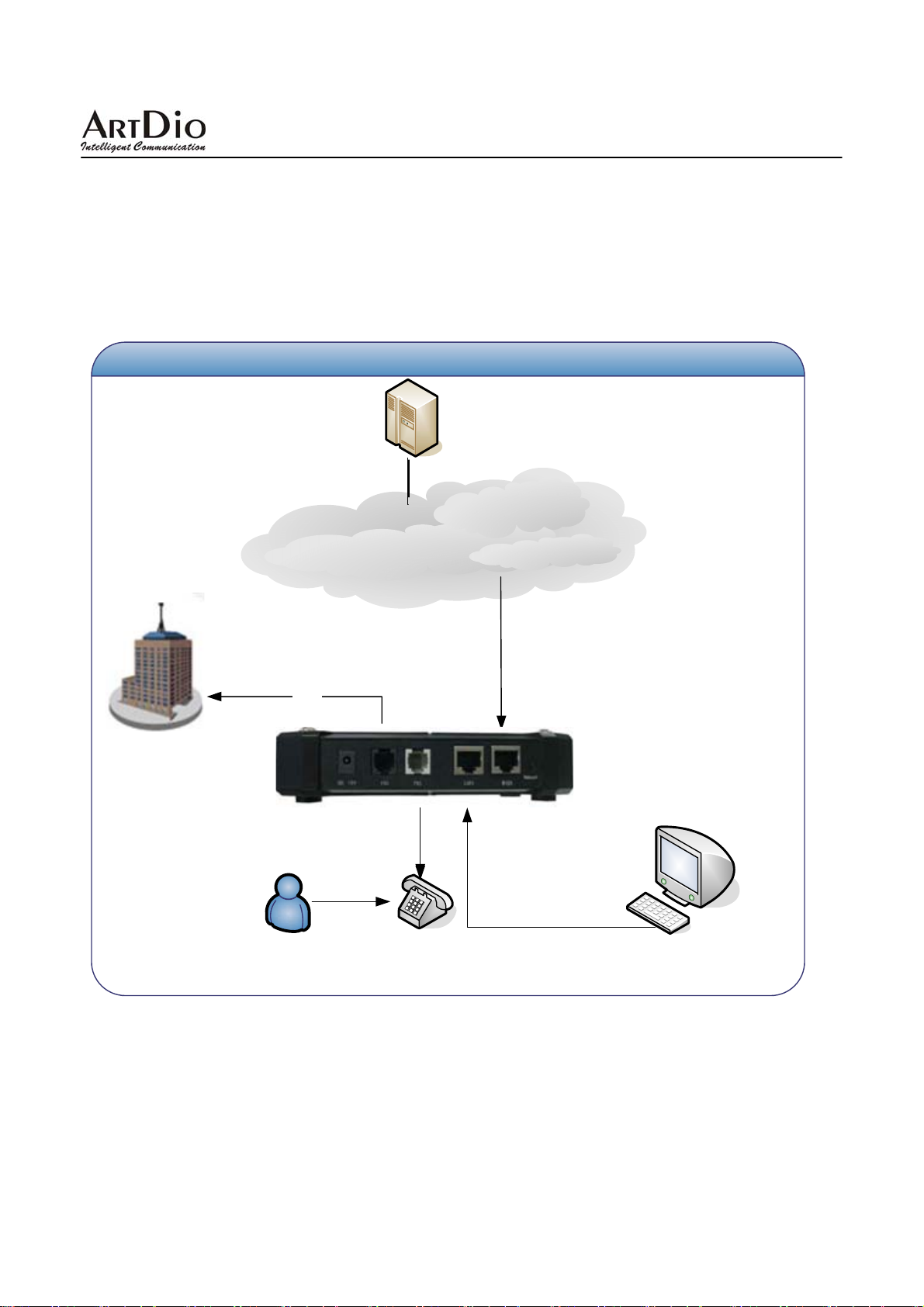
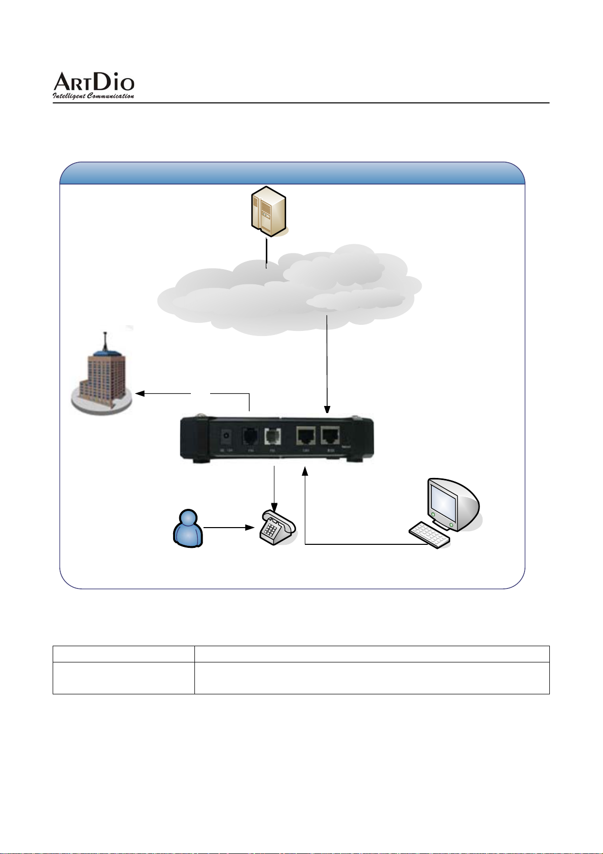
2.3 Network Installation and Setting
Network Setting (The image shown is IPS-2000 Series network setting, it could be used
by general users.)
Proxy
Internet
PSTN
user
PSTN
phone
IPS-2000Series
Ethernet Cable
PC
10
Page 11
IPS-2000 Series User’s Manual/使用手冊
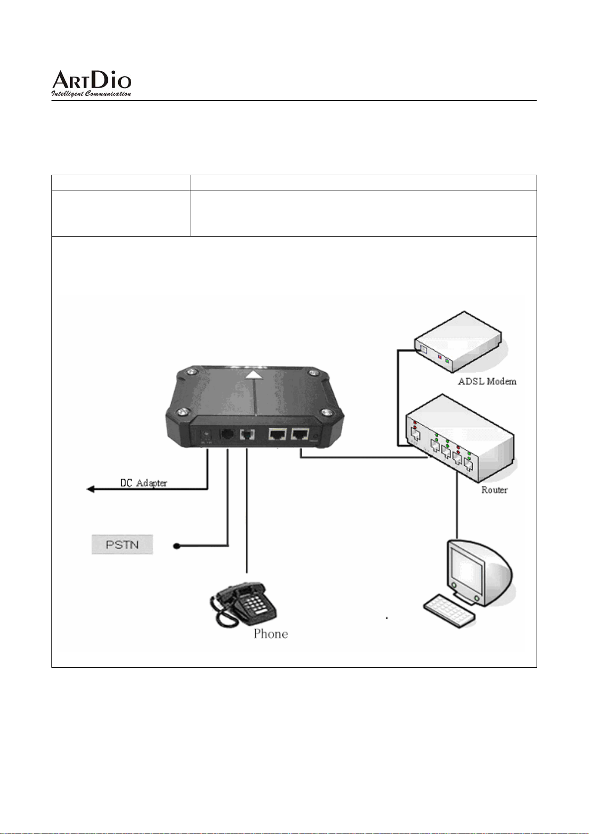
z Environment Setting
ISP Environment Suggestion
This setting is used only when your environment setting is using an IP router
IP Router Setting
IPS-2000 Series network setting with a Router is shown below:
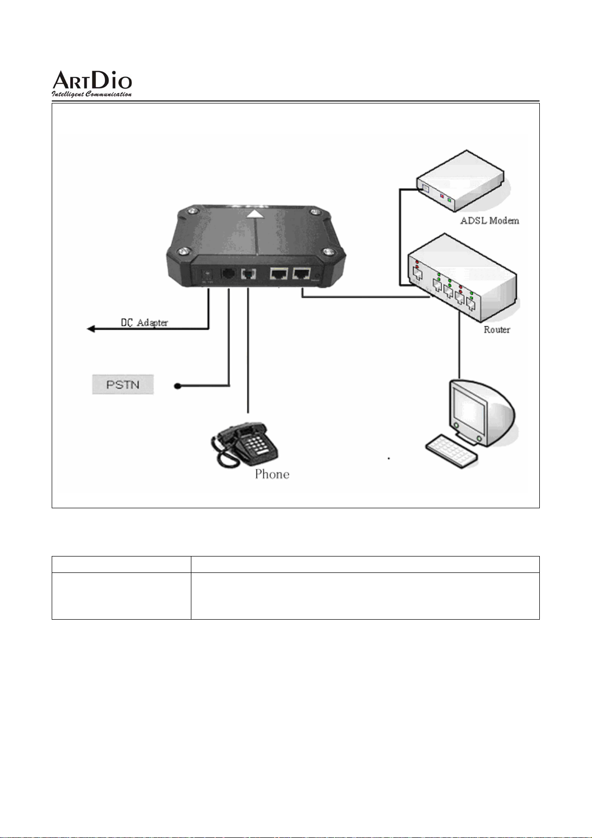
Connect the RJ-45 cable to the WAN (LAN2) port on IPS-2000 Series, and then connect the other RJ-45 to
the LAN port of IP Router.
and the router only serve as a network interface, which is similar to a
“Hub" connection.
11
Page 12
IPS-2000 Series User’s Manual/使用手冊
z Environment Setting
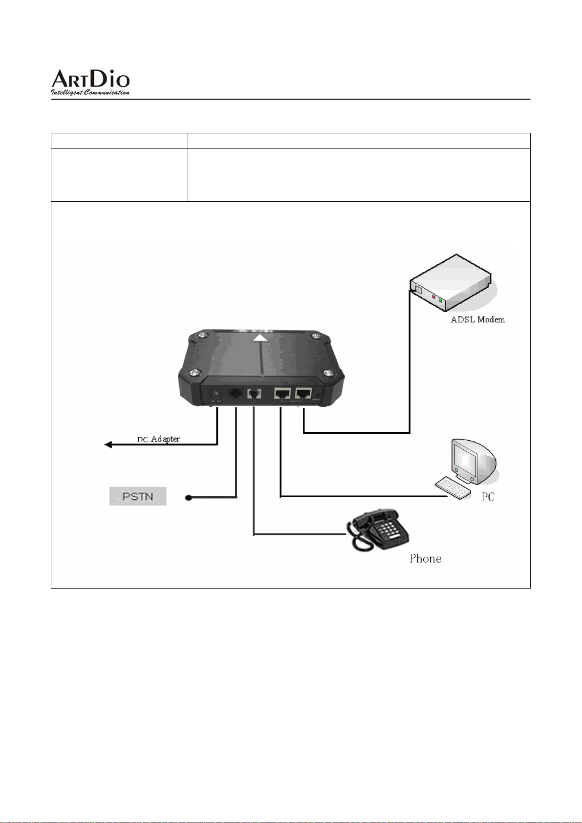
ISP Environment Suggestions
Network Setting without
IP Router
(General setting)
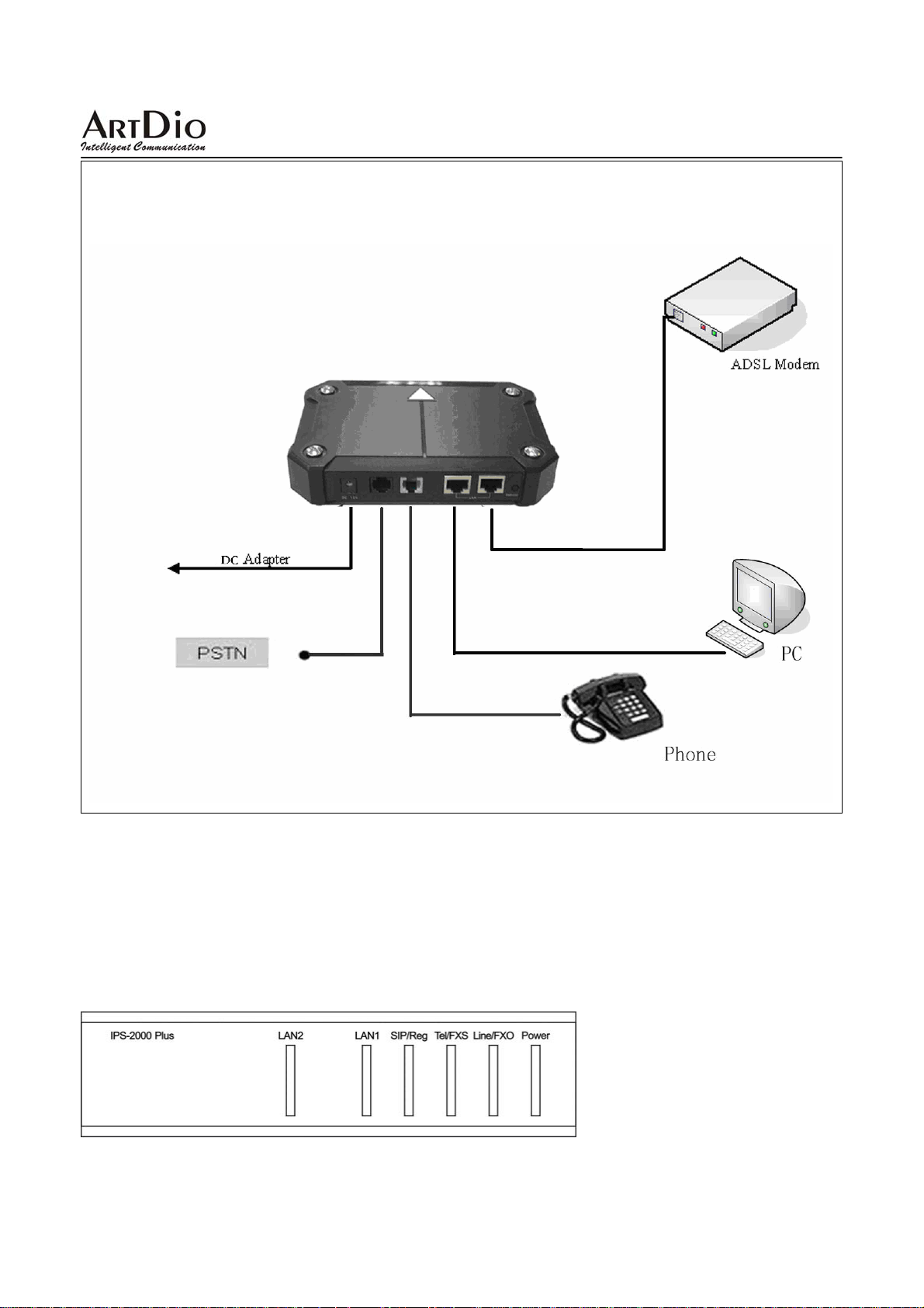
Connect the RJ-45 to the WAN (LAN2) port on your IPS-2000 series, connect the other RJ-45 to your
ADSL modem. The other LAN port on IPS-2000 series could be used to connect with PC or other
compatible Internet devices.
This is to connect IPS-2000 Series between ADSL modem and PC, suitable
for ADSL PPPoE (dynamic IP) user who has only 1 PC. Note ISP must
provide more than 1 dynamic IP.
z If you are not sure what environment setting , you should be using, please contact your ISP(Internet
Service Provider)
12
Page 13
IPS-2000 Series User’s Manual/使用手冊
2.4 System Registration and log on
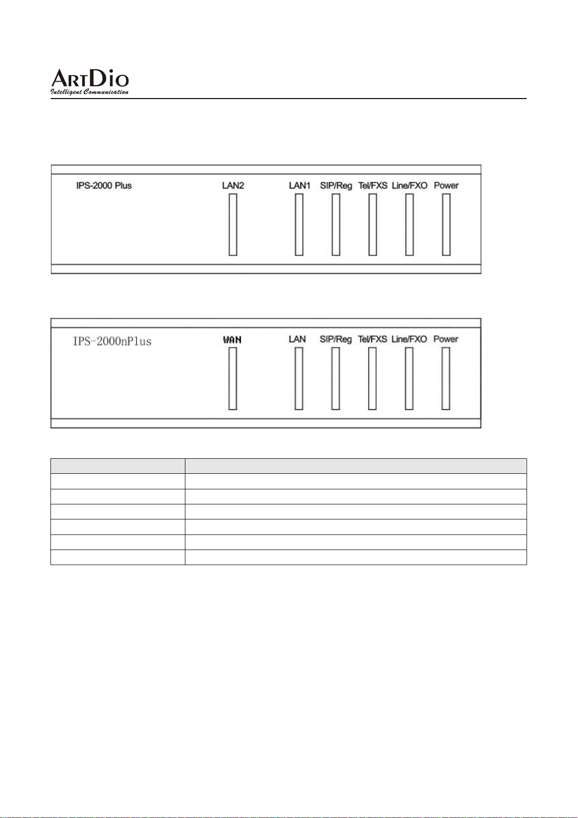
2.4.1 Status LED Indicator Explanation (suitable for IPS-2000 Plus)
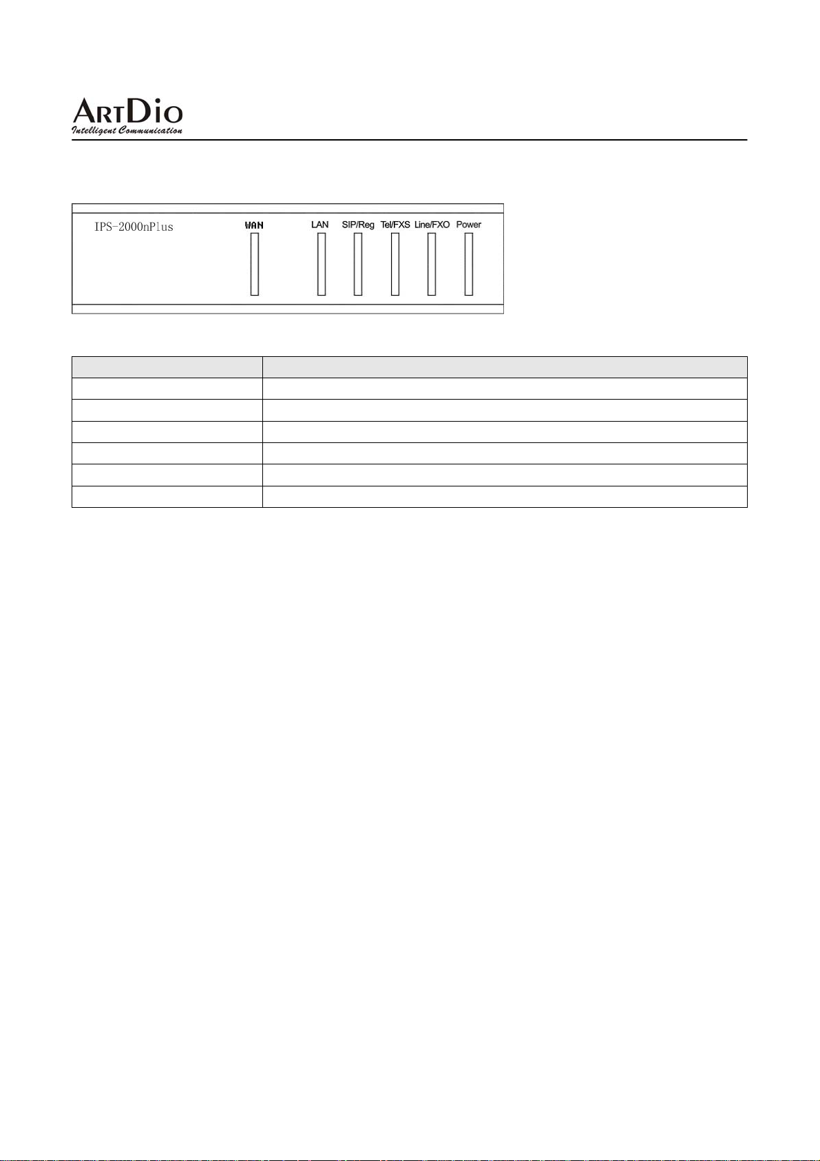
2.4.2 Status LED Indicator Explanation (suitable for IPS-2000NPlus)
Status LED Indicator Explanation
Power ON(Red) Red light On, power source is connected
Line/FXO(Blue) Blue light flash, PSTN line is in use
Tel/FXS(Blue) Blue light flash, Telephone line is in use
SIP/Reg (Blue) Blue light On, Registration successful
LAN(LAN1)(Blue) Blue light On, LAN(LAN1) is connected
WAN(LAN2)(Blue) Blue light On, WAN(LAN2) is connected
2.4.3 Quick Startup and Registration Guide
[ Step 1 Startup]
Plug into the power outlet, the power indicator turns on means the IPS-2000 Series is activated, followed by
the Tel/ FXS and SIP/ Reg indicator lights blinking, and then the LAN indicators turn on (LAN/LAN1
Indicator lights on, WAN/LAN2 Indicator lights on). When the stated indicators are turned on, the startup is
completed and it is connected to the Internet.
13
Page 14
IPS-2000 Series User’s Manual/使用手冊
[Step 2 Network Setting]
IPS-2000 Series support the IVR (Interactive Voice Response) system that allows the customers to
configure the IPS-2000 Series easily. Please follow the instruction below to set IP numbers.
1)Set IP, press #112 XXX*XXX*XXX*XXX#
2)Set Mask IP, press #113 XXX*XXX*XXX*XXX#
3)Set Gateway IP, press #114 XXX*XXX*XXX*XXX#
4)Set DNS Server, press #115 XXX*XXX*XXX*XXX#
Example:
Network default mode of IPS-2000 series is DHCP mode. If you want to or should use Fixed IP address,
please follow by step 2 to configure IPS-2000 series. If you need to change the static IP number to
192.168.1.12, follow the instruction given and enter #112192*168*1*12#, once the IPS-2000 Series reboot,
the setting is completed. Users are able to set the IPS-2000 Series to DHCP function, by picking up the phone
or putting it on speakerphone mode, follow the instruction and enter #111#. After the system reboot, it will
automatically picks up an IP number.
[Step3 Registration and Log on]
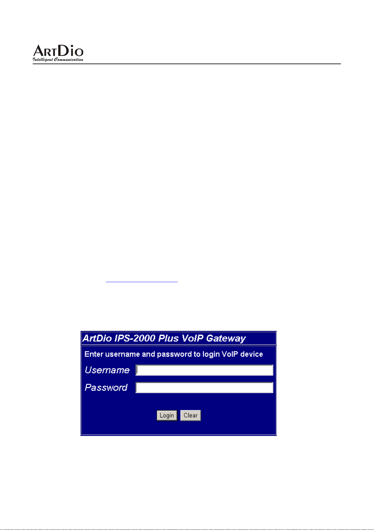
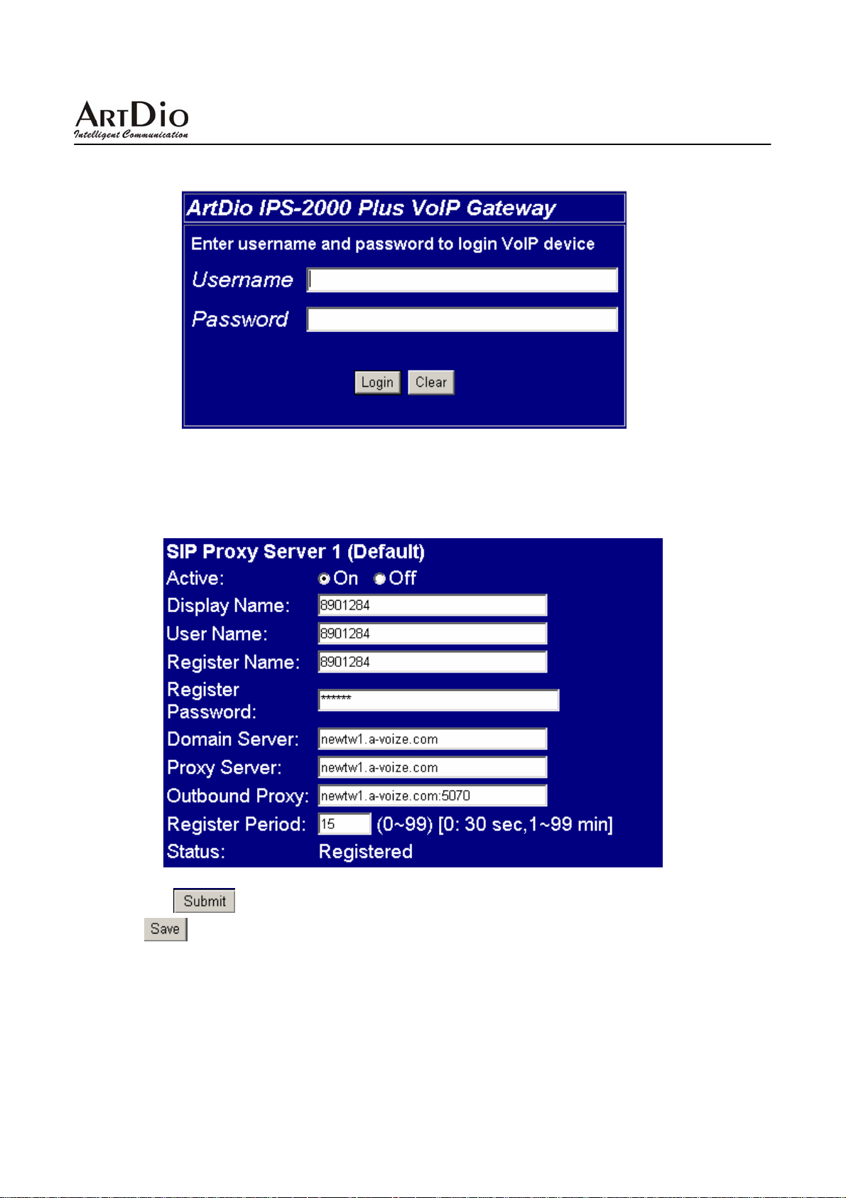
After startup is completed, pick up the phone or put it on a speakerphone mode, enter #126#.Untill you are
able to listen to IVR, please input the IP address in the Web page, and add the port number“9999"at the end
of IP address, as: http://IPS-2000 Series IP:9999 (Example: if your IPS-2000 Series IP address is
192.168.1.100, then input http://192.168.1.100:9999
) , then you will log on to the web page shown below. For
login , please input Username as “root" , and Password as“test", you can configure all the setting.(The
username “root" and password “test"are for initial log on only, customers can change the setting
anytime.)
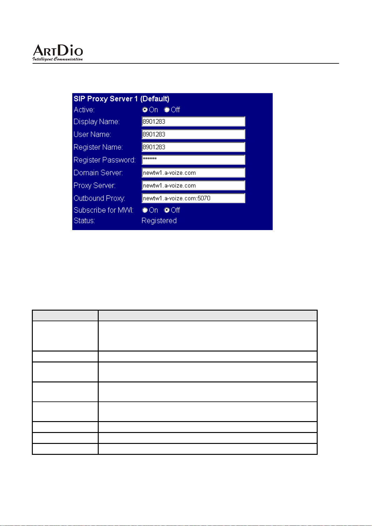
When you get into the Web Management interface, move the cursor to the SIP setting panel, click on the
14
Page 15
IPS-2000 Series User’s Manual/使用手冊
pull-down menu and select Service Domain, fill in the blanks at Service Domain Setting according to related
account information. You can configure the IPS-2000 Series as shown below. For example, the domain
registration of newtw1.a-voize.com with the port: 5070.
After the setting is finished, press submit key below to save the setting and press save change on the left to
store all the settings. Press “save" button and IPS-2000 Plus will restart.
*Remark: Register platform information like SIP Service Domain...etc. need to be provided by ISP.
2.5 IVR Interface for IPS-2000 Series
You can use the PSTN phone to configure the IPS-2000 Series.
Please follow the instruction to configure your IPS-2000 Series.
IVR Action
Switch IP mode
(Select VoIP or
PSTN mode)
Reboot
Factory Reset
Check LAN port IP
address
Check IP Type
Check Mask IP
Check Gateway IP
Check DNS IP
IVR Menu ◆ Notes
z * (default PSTN mode)
z 0* ( default IP mode)
#195# ◆The system reboot
#198# ◆The system reboot and all user-changeable will be lost and
return to factory default setting
#120# ◆Check the current IPS-2000 Series LAN port IP address
#121# ◆Check the current IPS-2000 Series IP type, static or
non-static
#123# ◆Check the current IPS-2000 Series Mask IP address
#124# ◆Check current gateway IP address
#125# ◆Check current DNS IP address
15
Page 16
IPS-2000 Series User’s Manual/使用手冊
Check WAN port IP
address
Check Firmware
Version
Set DHCP client
Set Static IP
Set Mask IP
Set Gateway IP
Set DNS Server
Set Codec
Set Handset Gain
Set Handset Volume
#126# ◆Check the current IPS-2000 Series WAN port IP address
#128#
#111# ◆Change to DHCP client setting
#112XXX*XXX*XXX*XXX# ◆every X represent a number
#113XXX*XXX*XXX*XXX#
#114XXX*XXX*XXX*XXX#
#115XXX*XXX*XXX*XXX#
#130+[1-8]# ◆(1)G711 u-Law, (2)G711 a-Law, (3)G723.1,
(4)G729a ,(5)G726 16K, (6)G726 24K, (7)G726 32K,(8) G726 40K
Set the codec you want to the first priority
#131+[00~15]#
#132+[00~12]#
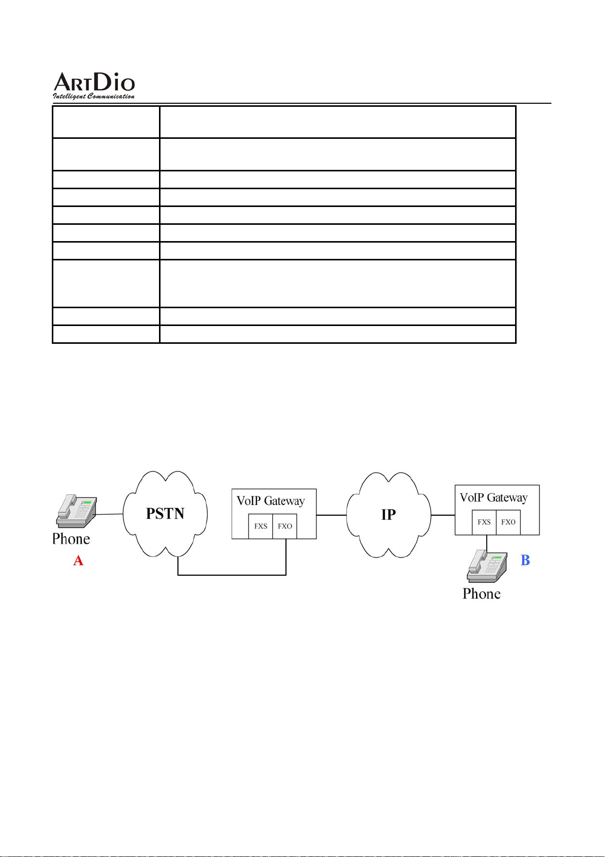
2.6 Inbound Function
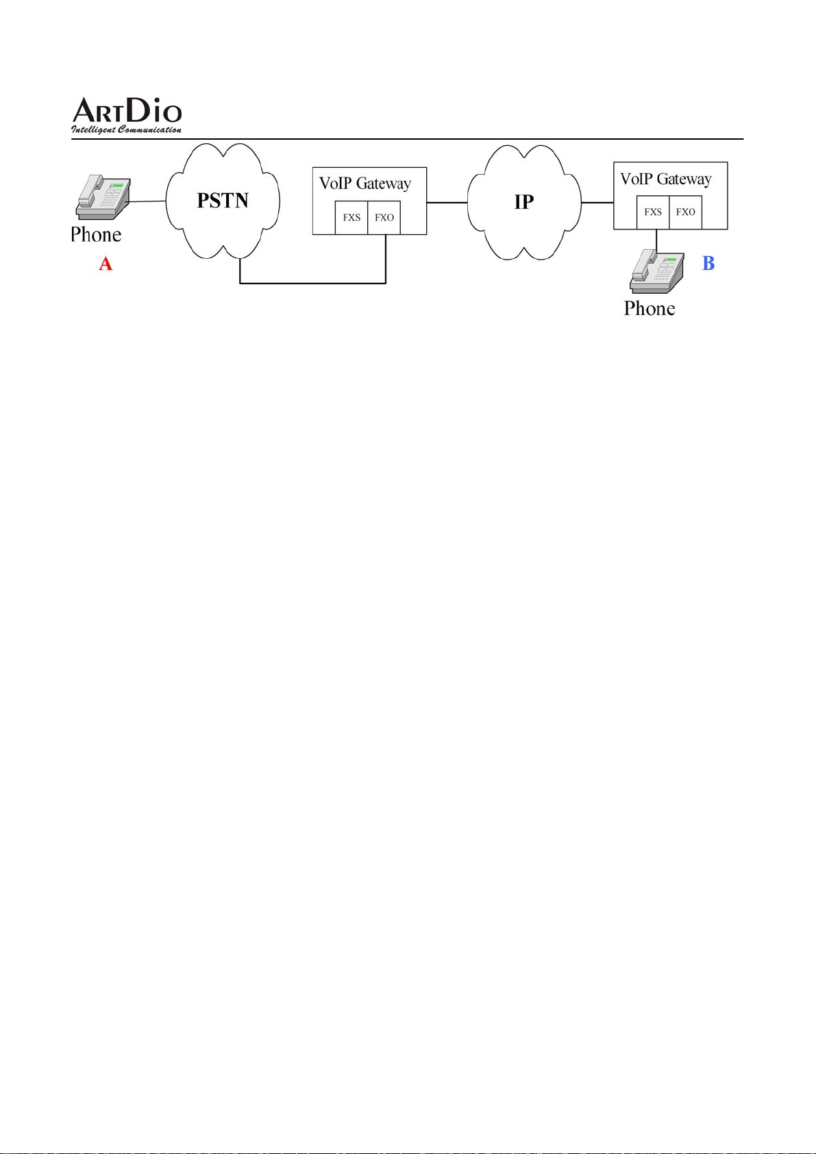
1.Inbound means making phone call from PSTN line into FXO port of
transit to the Internet and reach the other end of VoIP gateway FXS. The process as below(A->B):
IPS-2000 Series, then
2.Outbound means making phone call from FXO line into PSTN port of IPS-2000 Series, then
transit to the Internet and reach the other end of VoIP gateway FXO. The process as below(B->A):
IPS-2000 Series Inbound Steps
[Step 1 Account Registration]
First make sure the IPS-2000 Series is successfully registered with your ISP, have a SIP number assigned to
you and also have a PSTN number from local telephone company.
[Step 2 Active Inbound/Outbound Function]
16
Page 17

IPS-2000 Series User’s Manual/使用手冊
Set the Auto Answer function in the Phone Setting to ON.
• Inbound Operation:
You may directly get through from PSTN external cable, and a second dialing ring will come after several
rings (IPS-2000 Series will follow the vibrating ring) before it transfers to the phone number you need. If you
have set PIN CODE, you may hear some vibrating rings after getting through (IPS-2000 Series will follow the
vibrating ring). Then some urgent “Du""Du" rings will follow. You may enter PINCODE# to hear the
dialing sound for a second time before it transfers to the one you need.
• Outbound Operation:
Dial IPS-2000 Series SIP number. A second dialing sound will come after several vibrating rings (IPS-2000
Series will follow vibrating ring also) before it transfers to the one you need. If you have set “PIN CODE",
you may hear some vibrating rings after getting through. Then some urgent “Du""Du" rings will follow.
You may enter PINCODE# to hear the dialing sound for a second time before it transfers to the one you need.
Remark: During the waiting for 2nd dialing, phone will be hanging up if waiting too long.
17
Page 18
IPS-2000 Series User’s Manual/使用手冊
3. Web Configuration Page
Pick up the handset or press the speaker phone key, then dial #126# to hear your current IP address from the
IPS-2000 Series. Enter the IP address into your Internet browser URL address as “http://IP address:9999
enter configuration web page, input user name and password, the default user name is “root" and password
is “test", click “Login" button you will be able to get into the configuration web page of IPS-2000
Series.
In the configuration page, after the setting is finished, press submit key below to save the setting and press
save change on the left to store all the settings. Press “save" button and IPS-2000 Series will restart.
"to
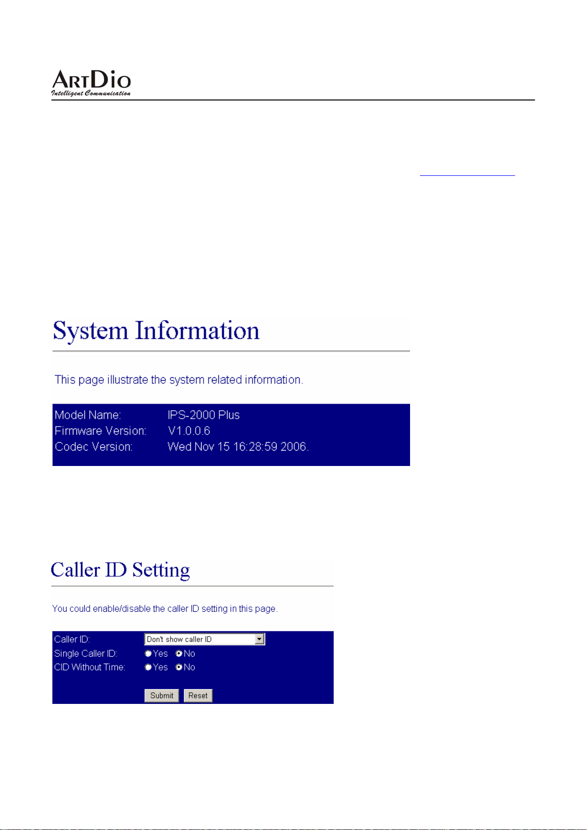
3.1 Information
System basic information, shows software version information.
3.2 Phone Setting
3.2.1 Caller ID
To configure the settings of the caller ID.
18
Page 19
IPS-2000 Series User’s Manual/使用手冊
Caller ID Setting
Field Name Description
Caller ID
Single Caller ID
CID Without T ime
Select display of caller ID, 4 options available, by FSK or DTMF
Select using single call ID or not
Set display time for calls.
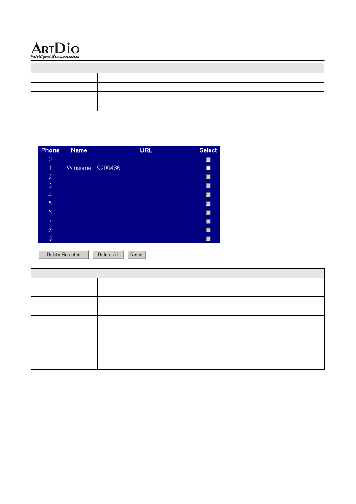
3.2.2 Phone Book
To configure the settings of the phone book and the speed dial.
PHONE Book
Field Name Description
Delete Selected
Delete All
Phone
Name
URL
Add Phone
Reset
Click to delete sel ected content.
Click to delete al l contents.
Field sequence.
Field name.
Field for telephone number
Add phone button. Enter phone number then click this button, name and
phone number will be filled into the fields accordingly.(Up to 140 phone
records)
Clear fields to re-enter data.
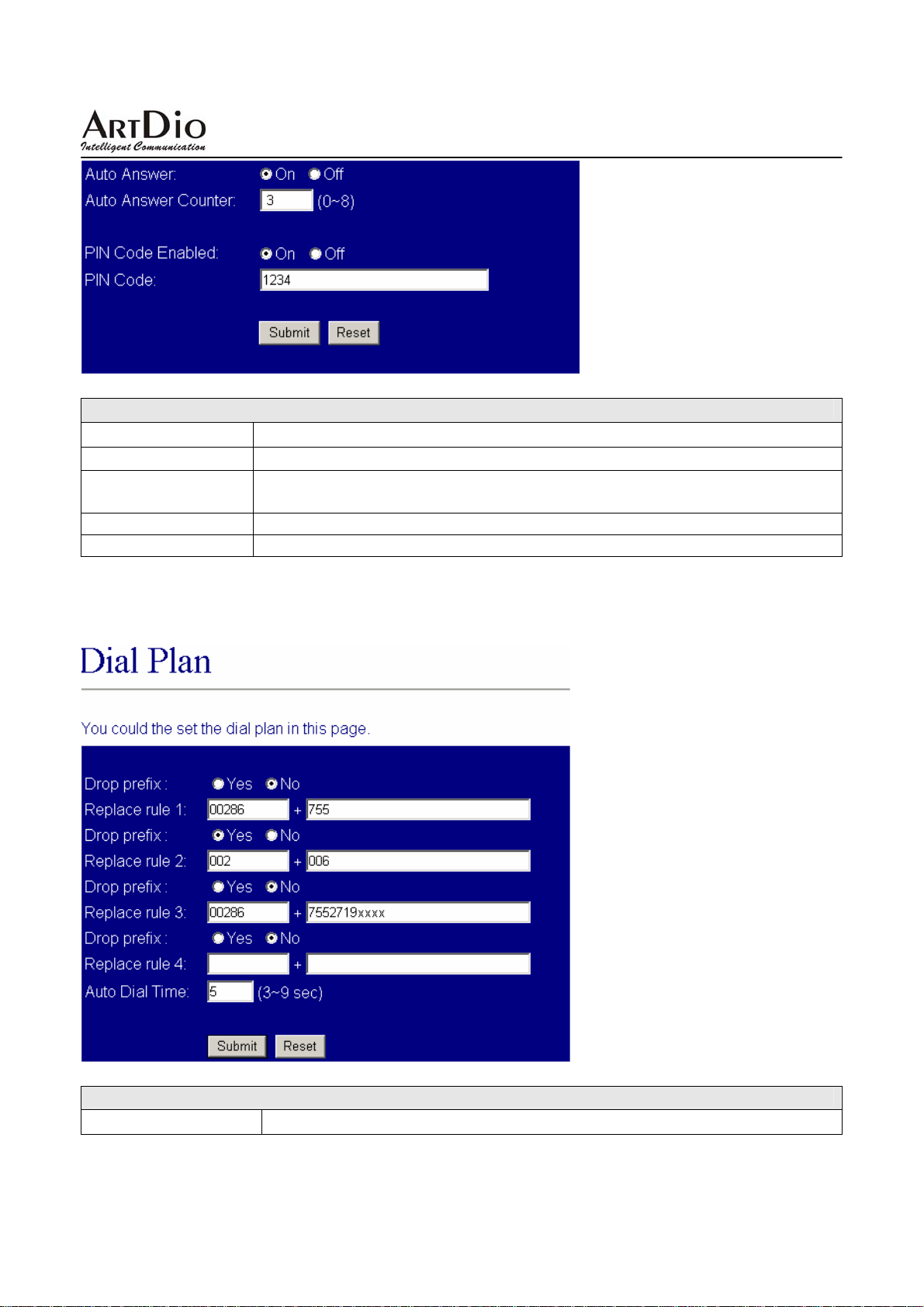
3.2.3 Auto Answer
To configure the settings of the Auto Answer.
19
Page 20
IPS-2000 Series User’s Manual/使用手冊
Auto Answer
Field Name Description
Auto Answer
Auto Answer
Counter
PIN Code Enabled Select to use password for 2nd dialing.
PIN Code Set the password for 2nd dialing.
Select this function will enable second dialing if has a call.
Auto answer ring time. Set how many rings to get into the silence mode for
2nd dialing
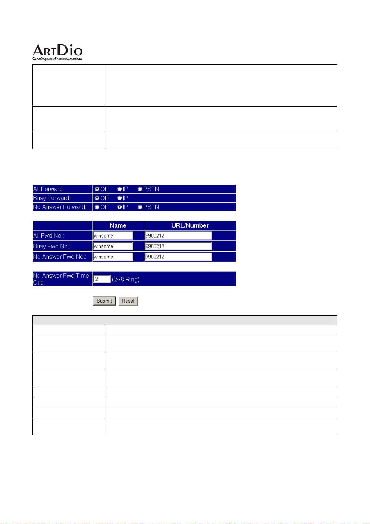
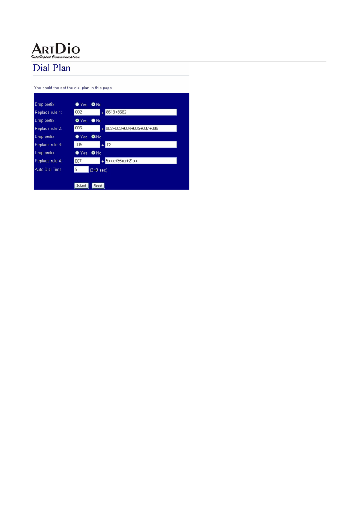
3.2.4 Dial Plan Setting
To configure the settings of the Dial Plan. (* Please refer to FAQ for details)
Dial Plan Setting
Field Name Description
20
Page 21
IPS-2000 Series User’s Manual/使用手冊
Drop Prefix Default to “No”.
- No (Add): When the dialing pattern matched, add to dialing number as a
prefix.
- Yes (Replace): When the dialing pattern matched, replace matched dialing
number.
Replace rule1 ~ 4 Set dial plan criteria
+: OR, multiple patterns can be separated with “+” which represents “OR”
x: represents 1 digit, xxx represent 3 digits
Auto Dial Time Set waiting how many seconds to dial out after entered all phone number
digits without enter the “#”sign.
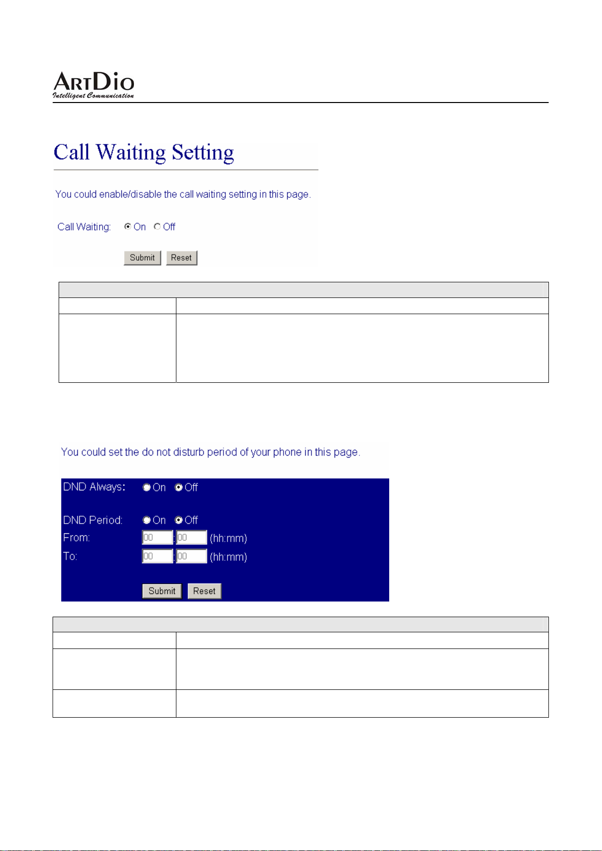
3.2.5 Forward Setting
To configure the settings of the Forward Setting.
Forward Setting
Field Name Description
All Forward
Busy Forward
No Answer Forward
All Fwd No
Busy Fwd No
No Answer Fwd No
No Answer Fwd Time
Out
Always forward. Every call will be forwarded to the telephone number in the
“All Fwd No.”-“URL” field.
If a call comes in when line is busy, call will be forwarded to the telephone
number in the “Busy Fwd No.”-“URL” field.
If a call comes in with no answer after certain of rings, call will be forward to
the telephone number in the “No Answer Fwd No.”-“URL” filed.
Enter the name and telephone num ber for forwarding.
Enter the name and telephone number for forwarding when line is busy.
Enter the name and telephone number for forwarding when no answer.
Set how many rings before a call times out.
21
Page 22
IPS-2000 Series User’s Manual/使用手冊
3.2.6 Call Waiting
To configure the settings of the Call Waiting.
Call Waiting
Field Name Description
To enable or disable call waiting function. While talking to A, B is calling,
at this time a beeping announce every 3 seconds to indicate a call is waiting,
Call Waiting
quickly press and release on hook/off hook button to put A call on hold and
switch to take B call . You can quickly press and release on hook/o ff hook
button again to keep B call on hold and switch back to take A call.
3.2.7 DND Setting
To configure the settings of the DND Setting.
DND Setting
Field Name Description
Do not disturb function. To block all incoming IP calls, make On checked.
DND Always
DND Period
All IP calls will hear a busy tone. Check off to disable this function. This
function does not effect PSTN call.
Time for activate Call Block function. Put start time in “From” field, put
end time in “To” field.
22
Page 23
IPS-2000 Series User’s Manual/使用手冊
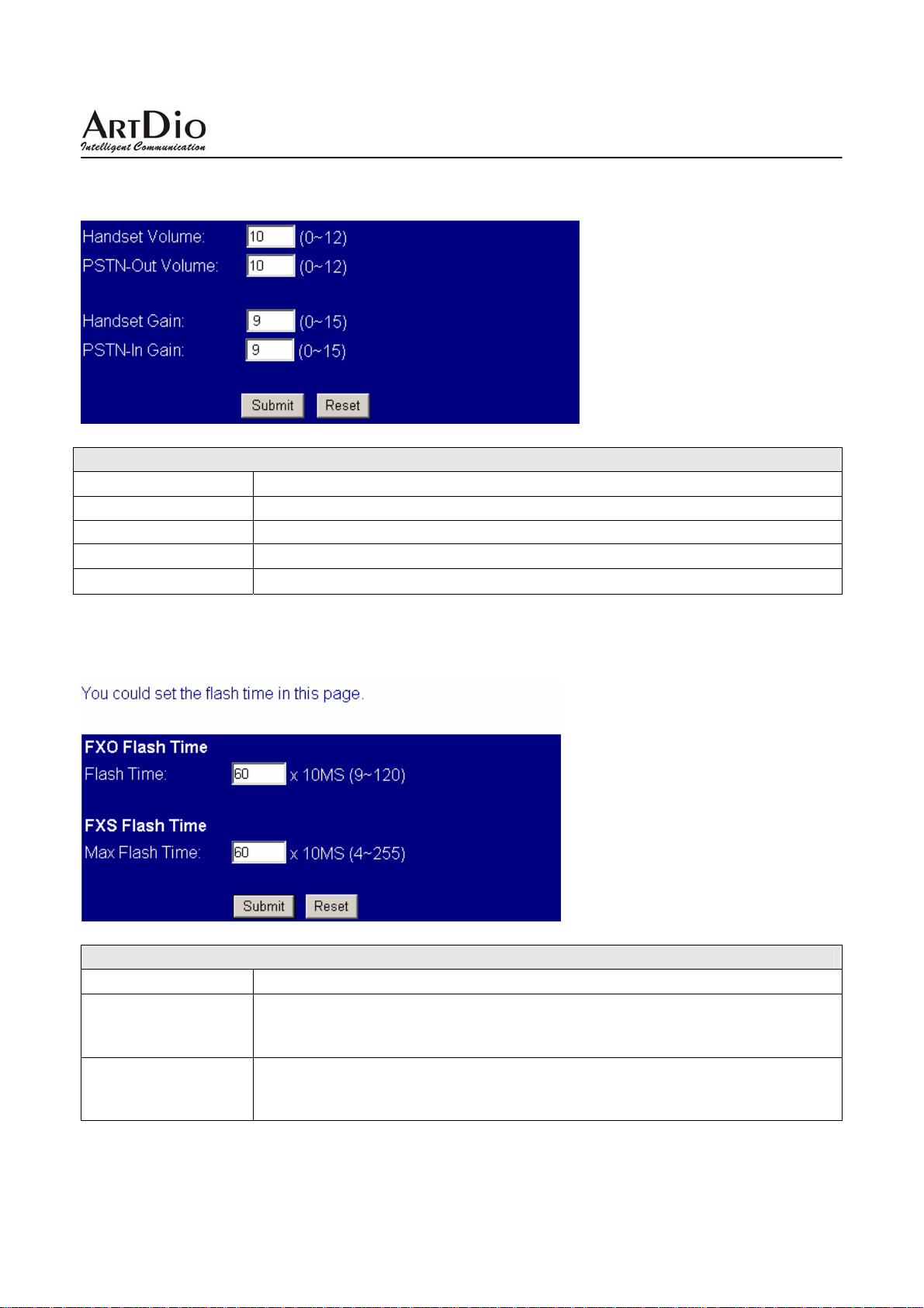
3.2.8 Volume Setting
To configure the settings of Volume setting.
Volume Setting
Field Name Description
Handset Volume
PSTN-Out Volume
Handset Gain
PSTN-In Gain
Adjust handset volume.
Adjust handset volume for using PSTN line.
Adjust microphone gain(suggest not to exceed 13)
Adjust microphone gain for using PSTN line.
3.2.9 Flash Time Setting
To configure the settings of the Flash Time Setting.
Flash Time Setting
Field Name Description
Set on hook/off button as a switch on FXO port. If press the on hook /off hook
Flash Time
Max Flash Time
button longer than the setting time will be treated as hang up. Less than the
setting time will be treated as switch.
Set on hook/off button as a switch on FXS port. If press the hook/off hook
button longer than the setting time will be treated as hang up. Less than the
setting time will be treated as switch.
23
Page 24
IPS-2000 Series User’s Manual/使用手冊
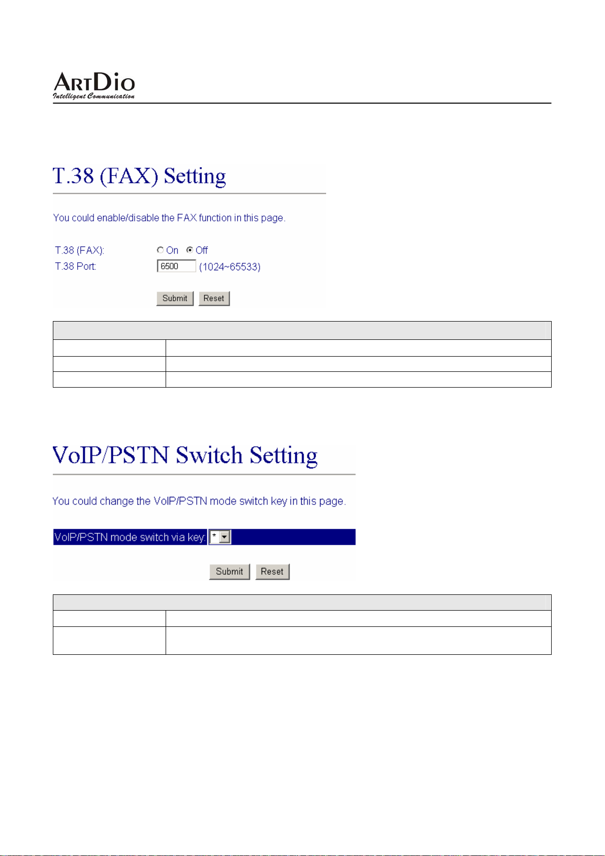
3.2.10 T.38 (FAX) Setting
To configure the settings of T.38(FAX) setting.
T.38 (FAX) Setting
Field Name Description
T.38(FAX)
T.38 Port
Set network FAX function.
Set FAX port.
3.2.11 VoIP/PSTN Switch Setting
To configure the settings of VoIP/PSTN Switch Setting.
Flash Time Setting
Field Name Description
VoIP/PSTN mode
switch via key
Select one key of the phone to switch to PSTN mode.
3.3 Networking
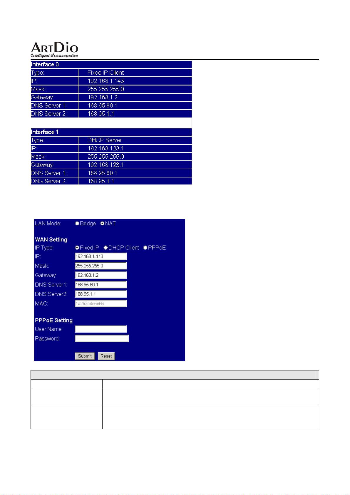
3.3.1 Status
To check the network status of IPS-2000 Series.
24
Page 25
IPS-2000 Series User’s Manual/使用手冊
3.3.2 Network Setting
To configure the network settings of the IPS-2000 Series.
Network Setting
Field Name Description
LAN Mode Bridge: Select to use bridge function.
NAT: Select to use NAT function.
Select proper network type according to your network environment.
IP Type
z Fixed IP : to use fixed IP, user need to fill out the IP information.
z DHCP Client : DHCP server will assign IP.
25
Page 26
IPS-2000 Series User’s Manual/使用手冊
z PPPoE: A type of broadband connection that provides authentication
(username and password) in addition to data transport. Such as ADSL
PPPoE dialup.
IP
Mask
Gateway
DNS Server 1
DNS Server 2
MAC
PPPoE Setting
User Name
Password
Set IPS-2000 Series IP address.
Set subnet mask IP address.
Set gateway IP address.
Set primary DNS IP address.
Set secondary DNS IP address.
MAC address.
While select PPPoE, enter ADSL account name.
While select PPPoE, enter ADSL account password.
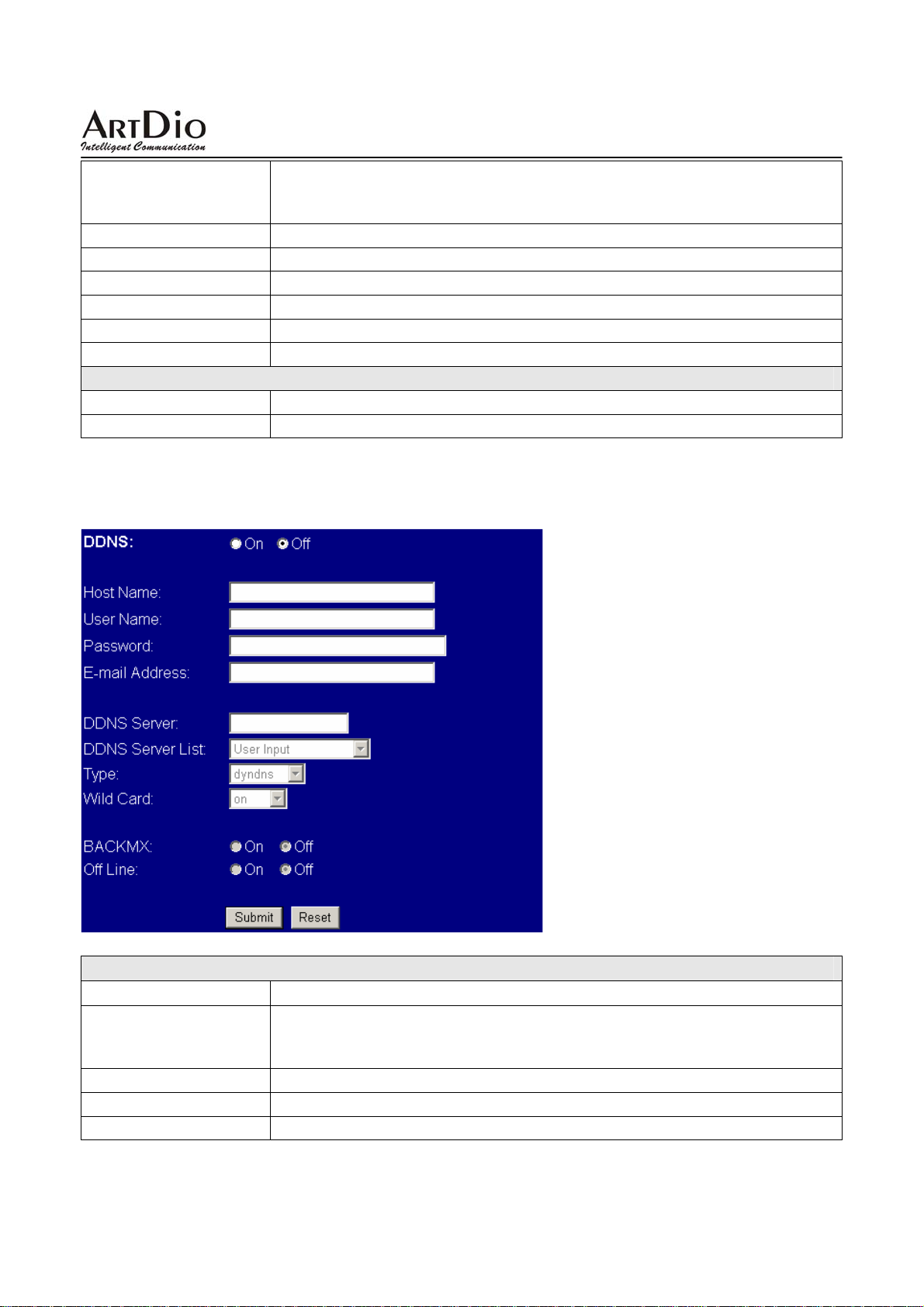
3.3.3 DDNS Setting
To configure the DDNS settings of the IPS-2000 Series.
DDNS Setting
Field Name Description
Set DDNS IP address, name and password to access. IPS-2000 Series is
DDNS
Host Name
User Name
Password:
design to work with SIP, please check DDNS related information to use this
function.
Host Name
User Name
Password
26
Page 27
IPS-2000 Series User’s Manual/使用手冊
E-mail Address
DDNS Server
DDNS Server List
Type
Wild ca rd
Back MX
Off Line
E-mail Address
DDNS Server
DDNS
Select DDNS work mode.
Select to use Wild card.
Check on to use Back MX.
Check on to use Off Line.
Server List
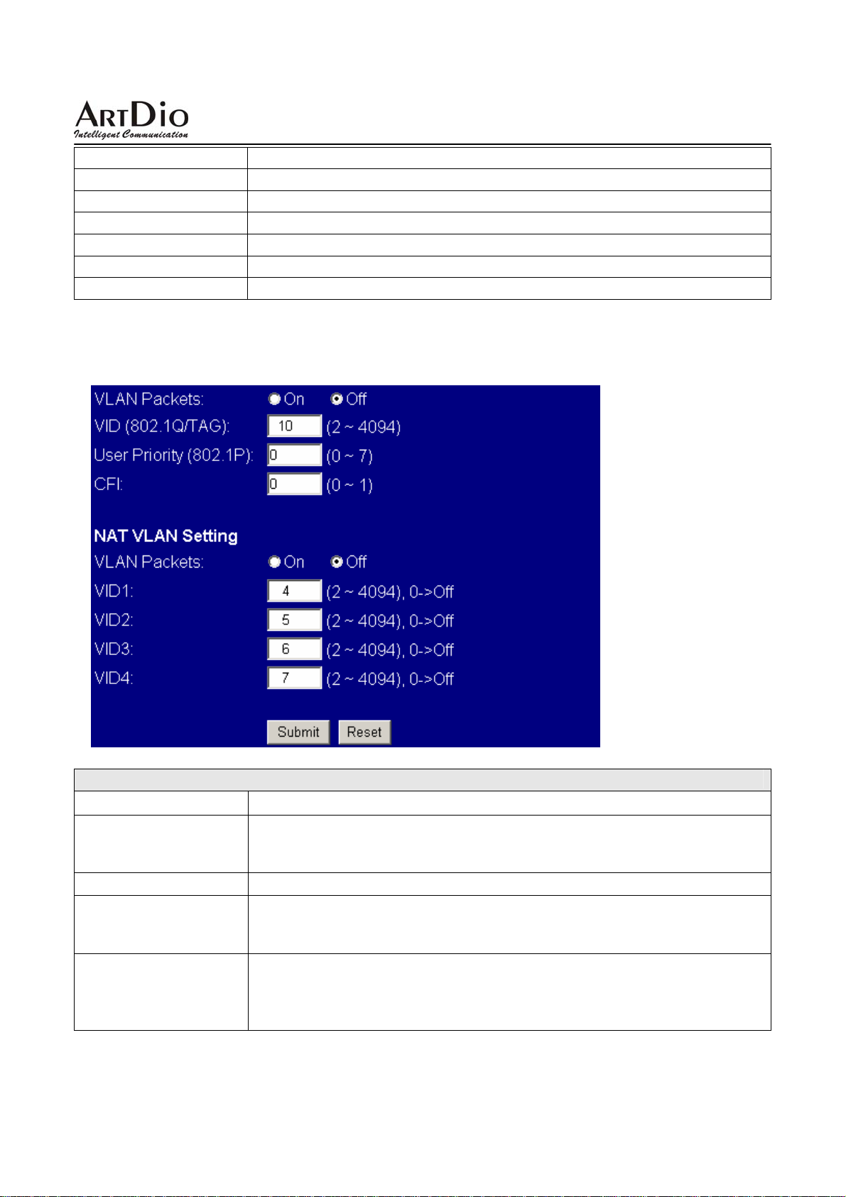
3.3.4 VLAN Setting
To configure the VLAN settings of the IPS-2000 Series.
VLAN Setting
Field Name Description
VLAN Packets Select to use VLAN Packets. If you enable the VLAN Packets and set the
VID, User Priority, and CFI, then all the incoming packets will be check
with the IP Address and the VID
VID Set the VID.
User Priority Defines user priority, giving eight (2^3) priority levels. IEEE 802.1P defines
the operation for these 3 user priority bits. Usually this will be defined by
your service provider.
CFI Canonical Format Indicator is always set to zero for Ethernet switches. CFI
is used for compatibility reason between Ethernet type network and Token
Ring type network. If a frame received at an Ethernet port has a CFI set to
1, then that frame should not be forwarded as it is to an untagged port.
27
Page 28
IPS-2000 Series User’s Manual/使用手冊
NAT VLAN Setting
VLAN Packets Select to use VLAN Packets. When you enable th e VLAN Packets and set
the VID, User Priority, and CFI, then all the incoming packets with the
IPS-2000 Series’ IP address and the same VID will be accept by the
IPS-2000 Series. If the incoming packets with the IPS-2000 Series’ IP
address but the different VID then the packets will be discard by the
IPS-2000 Series. The Other incoming packets with different IP address will
go through the LAN port to the PC.
VID1 ~ 4 Set the VID. When you set your device in NAT mode, IPS-2000 Series can
help you to filter the wrong incoming packets. You can separate the other
device connected behind the IPS-2000 series into 4 VLAN group. You can
set different VID for these 4 groups. When the incoming packets go through
the IPS-2000 Series’ WAN port then the IPS-2000 Series will check the
VID, if the packets is not going to the IPS-2000 Series (with the IPS-2000
Series’ IP address and the correct VID), and the VID is not these four VID
you set, then the packets will be discard by the IPS-2000 Series.
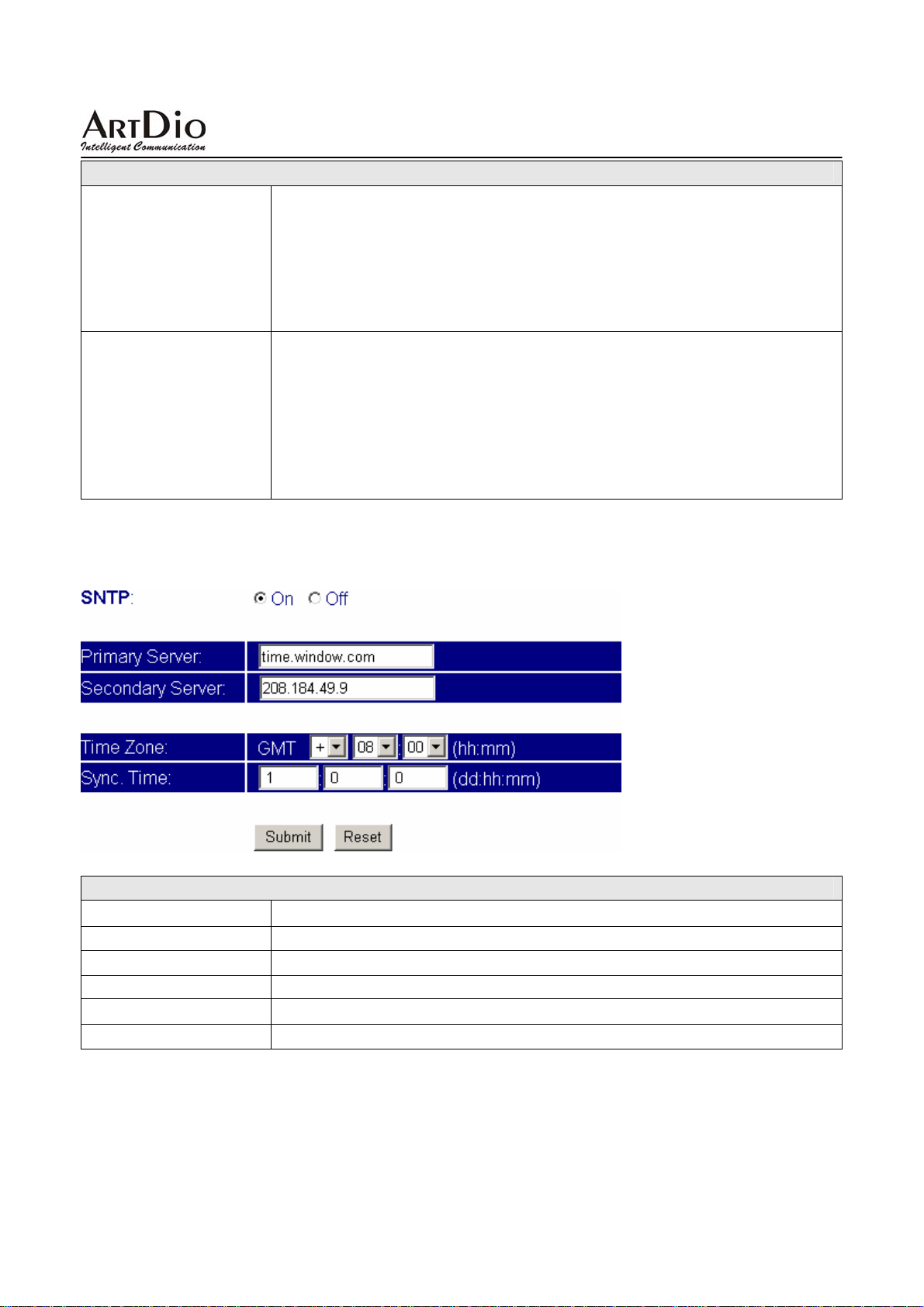
3.3.5 SNTP Setting
To configure the SNTP settings of the IPS-2000 Series.
SNTP Setting
Field Name Description
SNTP
Primary Server
Secondary Server:
Time Zone
Sync. Time
Set to use SNTP time Server, check on to use.
Primary SNTP Server.
Secondary SNTP Server.
Local time zone.
Sync. Time. Input the Sync. Time.
3.4 NAT Router
PS. Only IPS-2000N Plus has NAT router function. IPS-2000 Plus does not have NAT router function.
28
Page 29
IPS-2000 Series User’s Manual/使用手冊
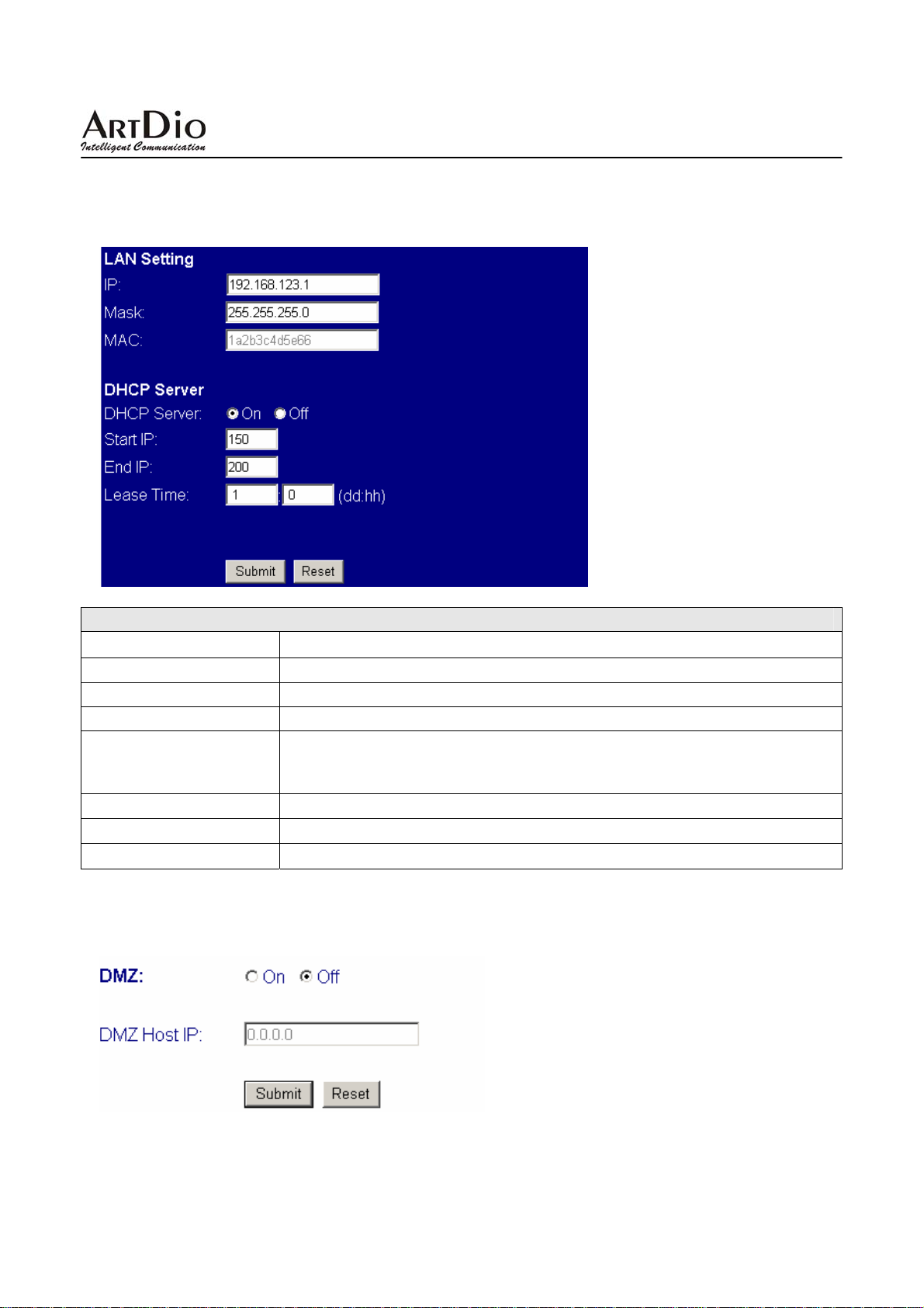
3.4.1 NAT Setting
To configure the NAT settings of the IPS-2000N Plus.
LAN Setting
Field Name Description
IP
Mask
MAC
DHCP Server
Start IP
End IP
Lease Time
Local IP address. Internal local area network settings.
Local Subnet Mask.
Local MAC address.
Set to use DHCP server, check on to use.2 A protocol that lets one device
on a local network, known as a DHCP server, assign temporary IP
addresses to the other network devices, typically computers.
DHCP start IP.
DHCP end IP
DHCP lease time. Provided by DHCP server.
3.4.2 DMZ Setting
To configure the DMZ settings of the IPS-2000N Plus.
29
Page 30
IPS-2000 Series User’s Manual/使用手冊
DMZ Setting
Field Name Description
DMZ Select to use DMZ. Removes the Router’s firewall protection from one
PC, allowing it to be “seen” from the Internet.
DMZ Host IP DMZ host IP address.
3.5 SIP setting
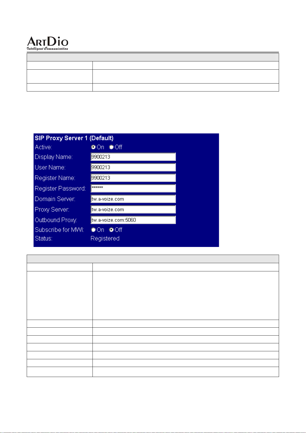
3.5.1 Service Domain
To configure the SIP service domain of IPS-2000 Series
Service Domain
Field Name Description
Make account active
z Up to 3 different SIP accounts can be registered and used in this page.
Check Active on , and fill in the SIP account information.
Active
Display Name
User Name
Register Name
Register Password
Domain Server
Proxy Server
Outbound Proxy
z Dial-out number is the first number registered (the first pick is the
number with “On” option). IF the first accounts could not be
registered automatically switch to register on the next account. Any
checked active and registered account can receive call.
Display Name
Account user name or phone number here.
Register name or phone number
Register password
SIP server domain or IP
SIP proxy server domain or IP
Voice proxy server
30
Page 31
IPS-2000 Series User’s Manual/使用手冊
Subscribe of MWI When set to “On” a Subscribe for Message Waiting Indication will be sent
periodically.
Status
Shows account register status
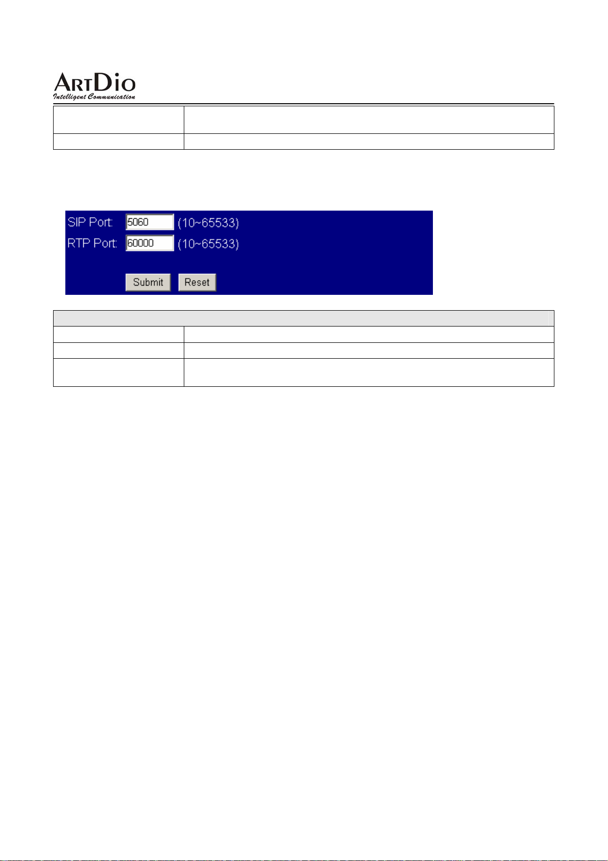
3.5.2 Port Setting
To configure the port mapping of the SIP service domain of your VoIP service provider.
Port Setting
Field Name Description
SIP Port
RTP Port
SIP register port, default to 5060
RTP port is for sending and receiving voice pocket. The port number can
be between 10-65533, but it must be even number.
31
Page 32
IPS-2000 Series User’s Manual/使用手冊
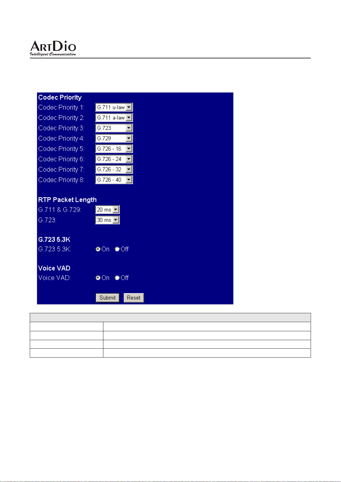
3.5.3 Codec Setting
To configure the voice code settings of the IPS- 2000 Series.
Codec Setting
Field Name Description
Codec Priority
G.723 5.3K:
Voice VAD
Set priority of selected voice codec.
When use G.723 codec, check on to use 5.3K rate.
Check on to use dynamic voice detection.
32
Page 33
IPS-2000 Series User’s Manual/使用手冊
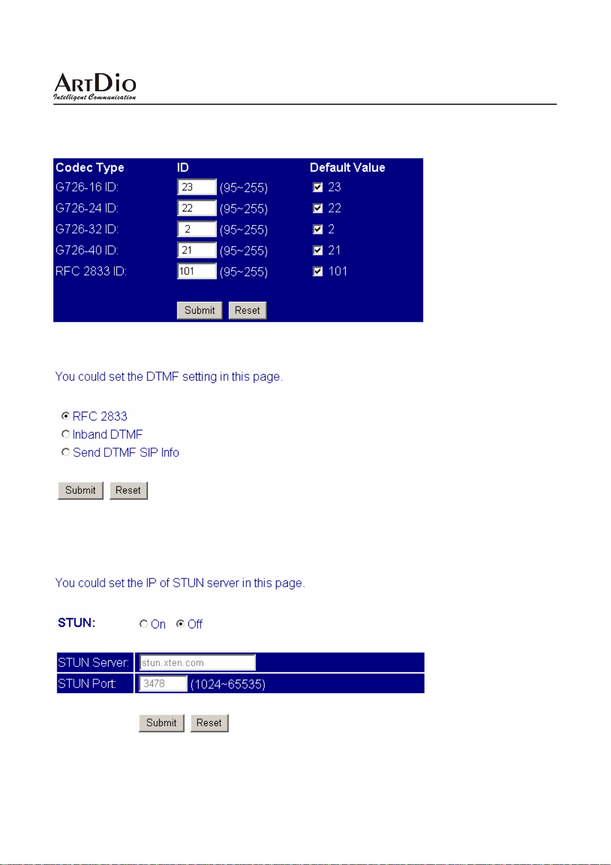
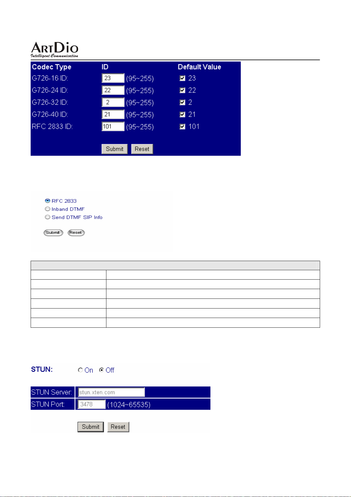
3.5.4 Codec ID
To configure the Codec ID of the IPS-2000 Series. Including all settings for G.726 codec, and setting for
RFC2833.
3.5.5 DTMF Setting
Inband DTMF and Send DTMF SIP Info selection, information provided by your ISP.
3.5.6 STUN Setting
To configure the STUN settings for SIP NAT pass-through.
33
Page 34
IPS-2000 Series User’s Manual/使用手冊
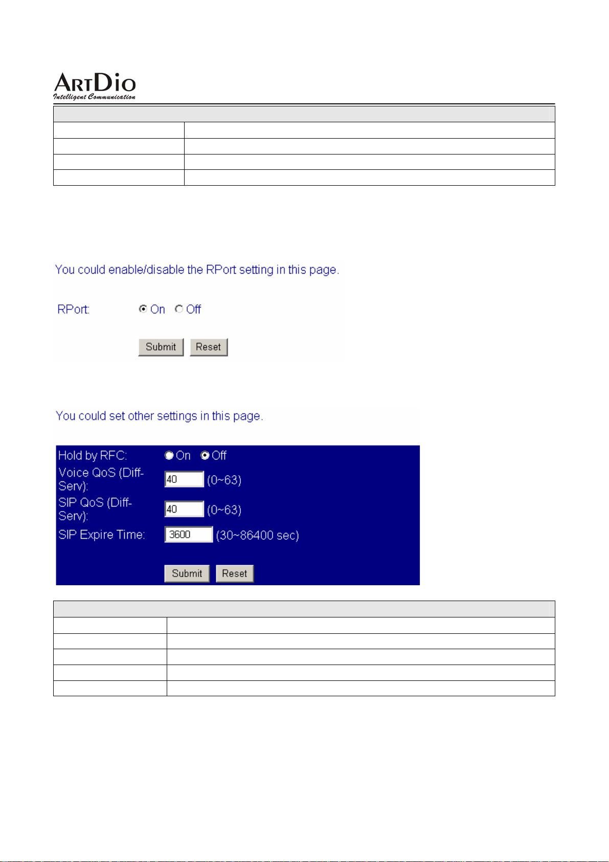
STUN Setting
Field Name Description
STUN
STUN Server
STUN Port
Check on to use STUN.
STUN server address.
STUN server port, default to 3478.
3.5.7 RPort Setting
Check on to use RPort.
3.5.8 Other Setting
Ohter Setting
Field Name Description
Hold by RFC
Voice QoS
Sip QoS
SIP Expire Time
Check on to use this function, this is provided by your ISP.
Set voice pocket size, bigger number means larger pocket size.
Set SIP pocket size.
Set SIP pocket transfer time.
34
Page 35
IPS-2000 Series User’s Manual/使用手冊
3.6 Others
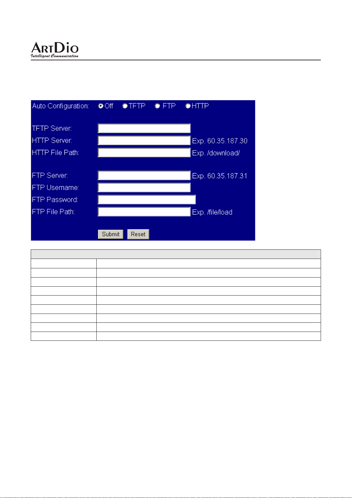
3.6.1 Auto Config
To configure the auto-configuration settings of IPS-2000 Series.
Auto Config
Field Name Description
Auto Configuration
TFTP Server
HTTP Server
HTTP File Path
FTP Server
FTP Username
FTP Password
FTP File Path
Check on to use firmware auto update function.
TFTP server address.
HTTP server address.
HTTP File save Path.
FTP Server address.
FTP Username
FTP Password
FTP File save Path
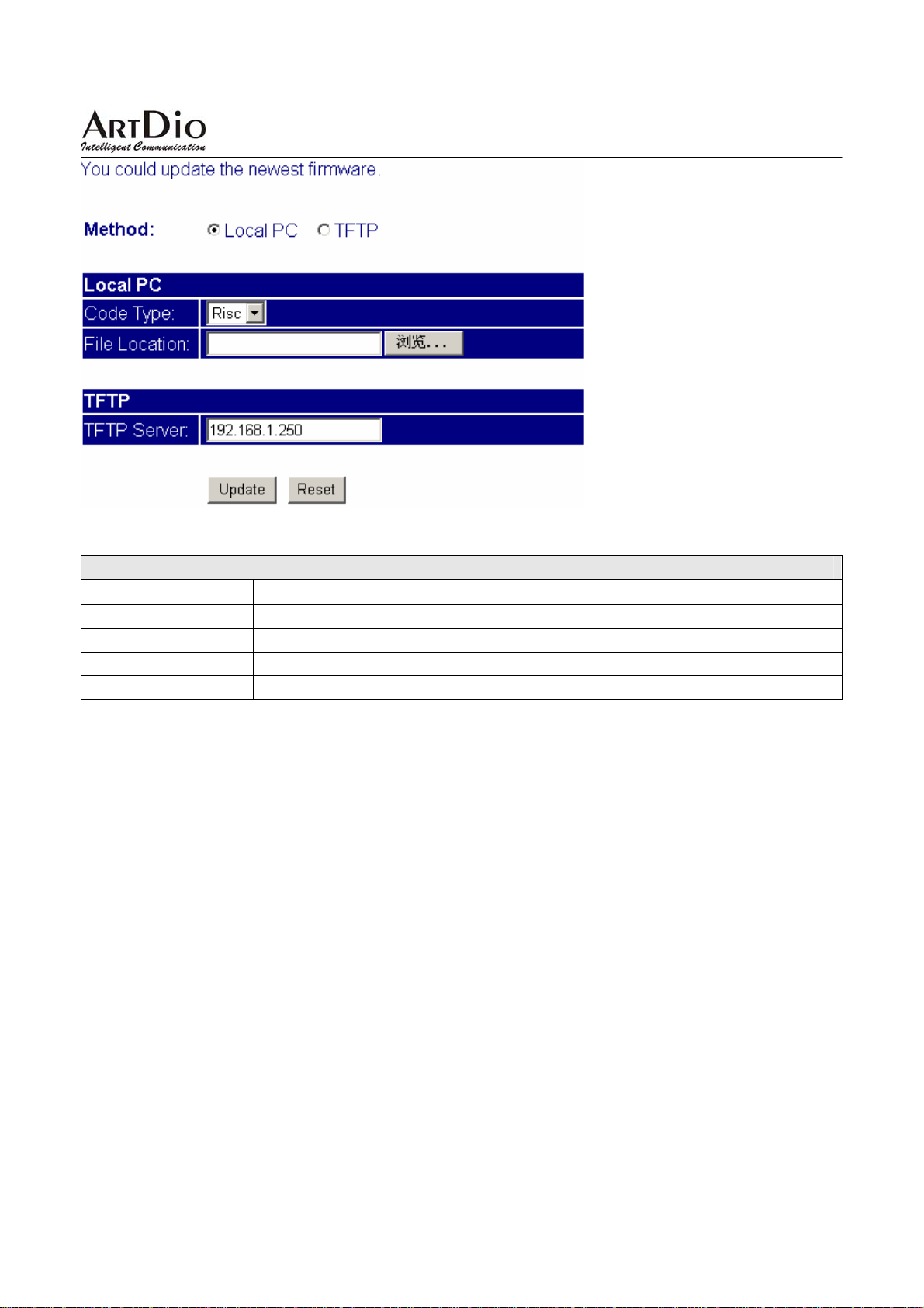
3.6.2 Firmware upgrade
To configure the firmware upgrade settings of the IPS-2000 Series.
35
Page 36
IPS-2000 Series User’s Manual/使用手冊
Firmware upgrade
Field Name Description
Method
Code T ype
File Location
TFTP Server
Select HTTP or TFTP to upgrade firmware.
Select upgrade code type, Risc or DSP.
Select firmware file save location path.
TFTP server address.
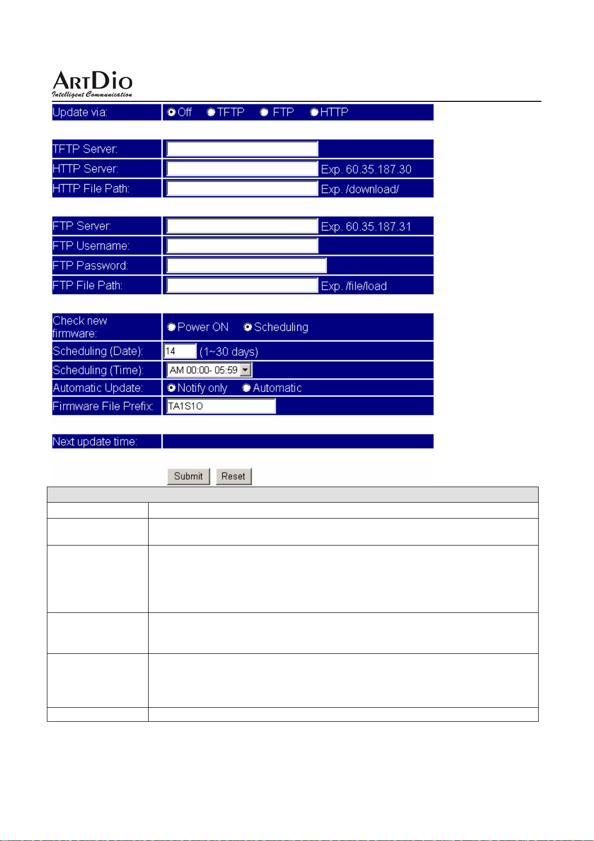
3.6.3 Auto update
To configure the Auto update settings of the IPS-2000 Series.
36
Page 37
IPS-2000 Series User’s Manual/使用手冊
Auto Update
Field Name Description
Update via Default is Off(Do not Auto Update). Automatically update environmental setting,
with TFTP, FTP and HTTP three ways
Check new
Firmware
Scheduling (Date) Default is 14 days, Every once in the days when the gateway check wh ether hav e
Scheduling (Time) Set time’s interval of checking new firmware for the gateway, Each section is
Automatic Update Automatically Updated, providing Notify only (notification messages only).
Default Scheduling( In accordance with schedules ). Checking Ways whether
have new Version for the Gateway
Power ON: Check whether have new Version for the Gateway at Power ON
Scheduling: Check whether have new Version for the Gateway In accordance
with schedules.
new firmware Version for it Auto Update, the shortest one day, the Longest thirty
days
automatically generated. provides 4 Section for User’s Selecting
AM 00:00-05:59,AM 06:00-11:59, AM 12 : 00-17:59 AM 18:00 - 23:59.
Default is AM00:00-05:59
37
Page 38
IPS-2000 Series User’s Manual/使用手冊
Automatic (automatically updated)
Default is Notify Only
-Notify only: Does not implement the action of Updating, Only provide
notification message to User.
-Automatic: If Scheduling has set , Gateway could automatically update New
Firmware version .But POWER ON ,need user to choose whether update the
new Firmware .
Firmware File
Prefix
Next update time Next checking or Updating date and time
Default Product model
Inspection Firmware version of the product model data
3.6.4 Default Setting
Reset to default setting.
3.6.5 Advanced Setting
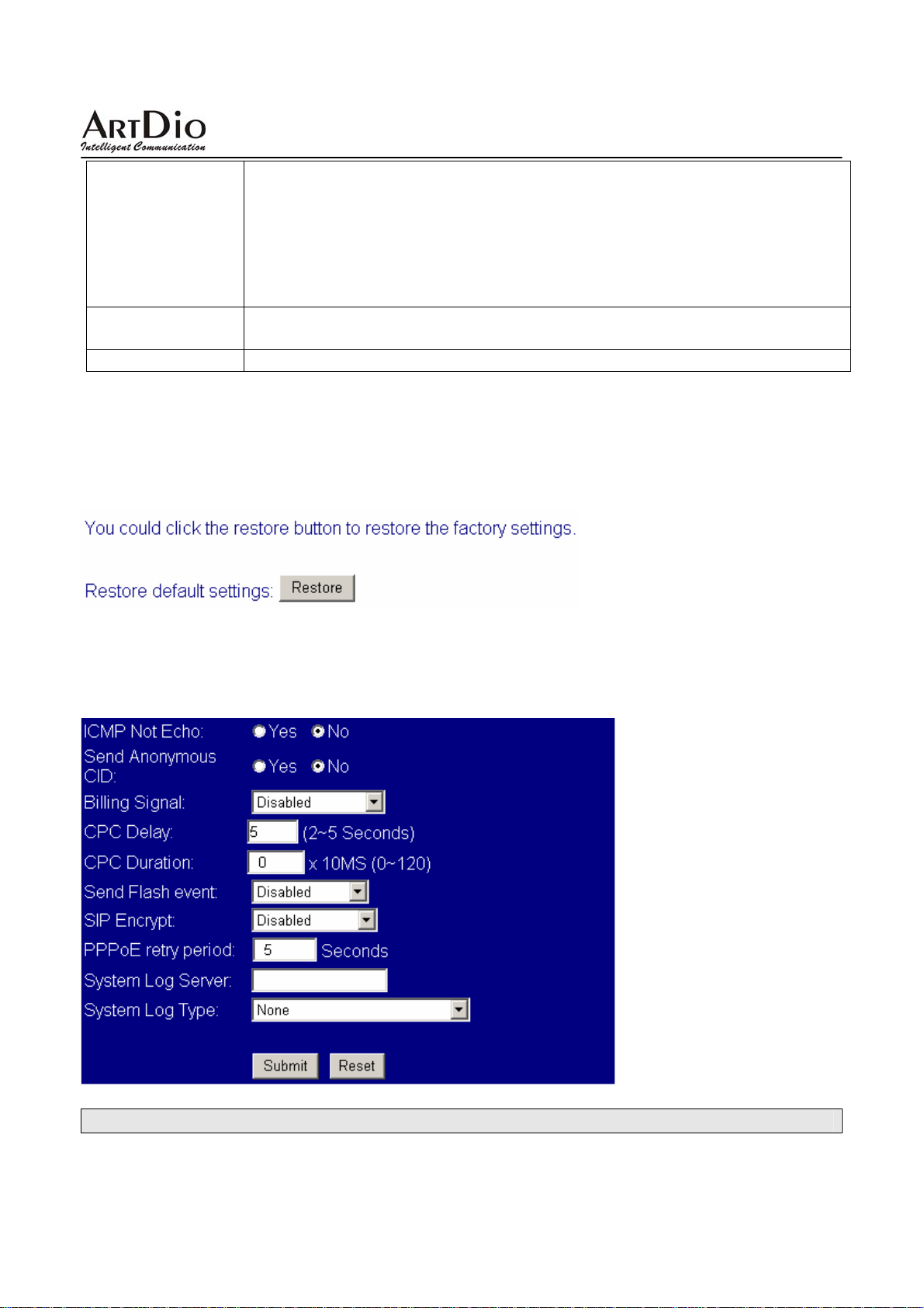
Select PTT type by country. Please check with your VoIP service provider if you would like to change
the settings.
Advanced Setting
38
Page 39
IPS-2000 Series User’s Manual/使用手冊
Field Name Description
ICMP Not Echo Default No, responding to the message of ping, if select “Yes" not
responding to the message of ping.
Send Anonymous CID Default No, Have no Call out security function, send information of the
Gateway, if Select “Yes"do not send information of the Gateway
Bill signal Default Disable. Turn on polarity reversal functions to notice Billing system.
(Polarity Reversal, Tone_12K, Tone_16K). Support FXS Port
CPC Delay Default 2.When received the hang-up signal, how many seconds need to wait
to drop the Voltage to Zero. Support FXS Port.
CPC Duration Default time is 0ms.(No voltage dropped) When voltage dropped to Zero, how
many ms need to continue. Support FXS Port.
Send Flash event Default Disable , User could Select DTMF Event or SIP Info to Send flash
event.
SIP Encrypt Default Disable , IPS-2000 Plus have INFINET, AVS, WALKERSUN1.
WALKERSUN2 four format for SIP encryption.
This service is provided by use environment.
PPPoE retry period Default is 5 Seconds. Set interval is [5~255]. When PPPoE dial failure, how
many seconds need to wait before redial.
System Log Server Provide system information which to store Log server address at the System.
System Log Type Default None (Disable).System Log information type. Provided None, Call
Statistics, General Debug, Call Statistics + General Debug, SIP Debug, Call
Statistics + SIP Debug, General Debug + SIP Debug, All.
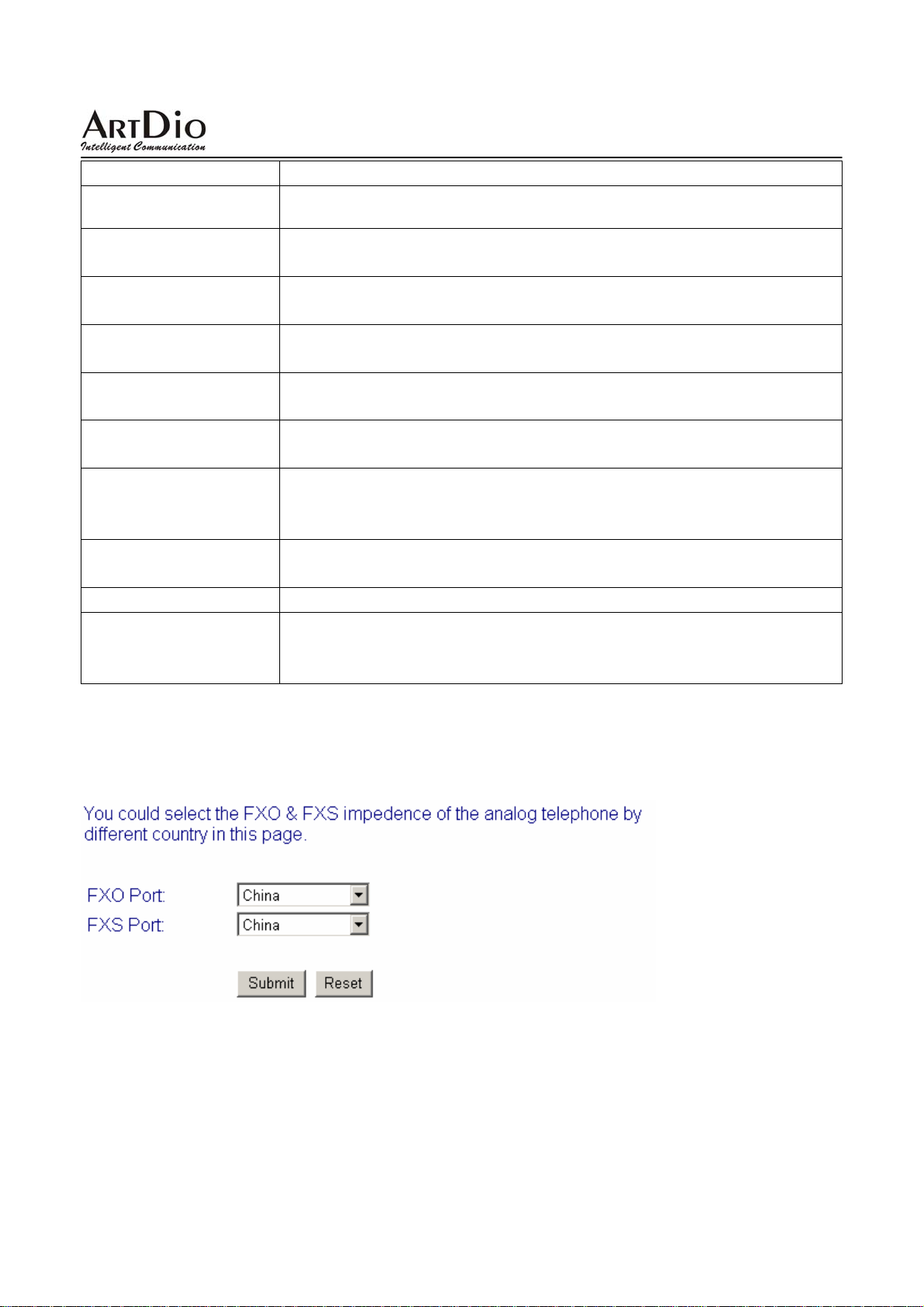
3.6.6 FXO & FXS port
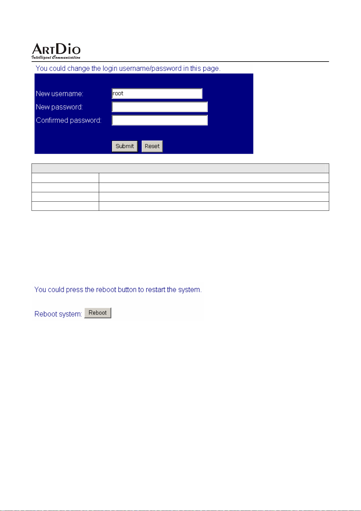
3.6.7 System Auth
To configure the user logins of the IPS-2000 Series.
39
Page 40
IPS-2000 Series User’s Manual/使用手冊
System Auth
Field Name Description
New username
New password
Confirmed password
System user name for IPS-2000 Series setting login.
Set new password.
Repeat new password to confirm.
3.7 Save Change
Click “Save” to save all changed settings, then IPS-2000 Series will restart.
3.8 Reboot
Click “Reboot” button to reboot the system.
40
Page 41
IPS-2000 Series User’s Manual/使用手冊
4. Product Specifications
Voice Interface
Call Control Protocol SIP v1 (RFC 2543), v2 (RFC 3261)
G.711 (64k bit/s, PCM), G.723.1 (6.3k / 5.3k bit/s), G.726 (16k / 24k / 32k /
Voice Compression
Delayed (Point to
Point)
Echo Cancellation
Flow of the Average 5.3K(G.723.1) ~ 64K(G.711) bps
Other Support In-Band DTMF, Out-of Band DTMF, SIP Info
LAN Interface
Interface Spec 10/100Mbps Fast Ethernet
Interface Connector RJ-45 Connector
Management Web Browser
IP Address
Firmware Update HTTP / TFTP / FTP
Call Features
Other Specs.
Input AC/DC Range 100 – 240VAC, 50 – 60Hz, 12VDC
Power Consumption 6W
Operation
Environment
Weight 288g
Certificates CE / FCC
Dimensions 165mm *110 mm *35 mm
Others
40k bit/s, ADPCM), G.729A (8k bit/s, CS-ACELP), G.729B (adds VAD &
CNG to G.729)
< 100ms
Packet Loss Compensation, Adaptive Jitter Buffer, VAD (Voice activity
detection), CNG (Comfortable noise generator), AEC (Acoustic echo
canceller), G. 165 (LEC, Line echo canceller), G.168 (EC, Digital netwo rk echo
canceller)
Static IP / DHCP Client / PPPoE Client / TFTP Client / HTTP Server / DNS
Client / Telnet / SNTP / RTP / RTCP / DDNS
Call Hold / Call Waiting / Call Forward / Call Transfer / Caller ID / Call Block
/ 3-way Conference
Working Temperature : 0 ~ 40℃ (32° ~ 104°F)
Storage Temperature : -30 ~ 65℃ (-22° ~ 149°F)
Relative Humidity: 10 ~ 95% Non-Condensing
140 Phone Contacts
IVR in English version
NAT Pass-through ( STUN / uPnP / R-Port )
Networking Status, Firmware Update, No Answer Forward, Busy Forward, All
Forward, Web Management, LED indicators
41
Page 42

IPS-2000 Series User’s Manual/使用手冊
5. Frequently Asked Questions (FAQ)
1. How to confirm the IPS-2000 Series is successfully registered?
If IPS-2000 Series is successfully registered, the register indicator will be on. If the light is not on
means the registration failed. Normally the IPS- 2000 Series regi stration process takes about 2
minutes to be completed.
2. After connected to a power outlet, the power indicator is on, but WAN(LAN2) i ndicator is not
on, why?
Please check your cable connector if it is loose. Or else, please check your Internet connection with
the server.
3. Can I dial the phone if a blackout occurs?
If the power is cut off , the IPS-2000 Series do not have power supply which means the Gateway
would not be able to receive and make phone calls. But the PSTN phone line is able to function as
normal to receive and make calls.
4. Does it support PSTN inbound call?
Yes, it supports PSTN Inbound Call. Inbound Transit means that users use a PSTN line to make calls
to IP telephone which connected a PSTN line, and this call will be forwarded to another Gateway
through IVR answer function.
How to Dial An Inbound Transit Call:
Dial a call to your IP telephone through the PSTN line, you will hear a dial tone after the phone rings
(3-9) times, and dial the SIP account number. If PIN code is set you need to input the PIN code
before dialing the SIP number.
5. How to make a PSTN phone call?
If Default is PSTN mode, pick up the phone, after you hear a dialing tone then dial a PSTN number.
If Default is IP mode, pick up the phone, press the default “*” sign to switch to PSTN mode, once
you hear a dial tone, you can dial a PSTN number.
6. How to make a call to IP phone number?
If Default is PSTN mode, pick up the phone, press the default “*” sign to switch to IP mode, once
you hear a dial tone, you can dial the number following by a “#” sign.
7. How to use the “Hold” function?
When you are on a call, press the “hold” key or swap key to keep the called party on hold.
42
Page 43

IPS-2000 Series User’s Manual/使用手冊
8. How to use the Call Waiting function?
When you are on a call, you will hear an alert tone means you receive a second incoming call. If you
want to answer the new call, press “hold” key or “Swap” key to switch to the new party.
9. How to use Call Transfer?
Blind Transfer
When you are on a call with A and want to transfer the call to B, press “flash” or “hold” key to keep
A, then press #510# and dial the B party’s number followed by a “#” sign, the call will transfer to B.
Attendant Transfer
When you are on a call with A and want to transfer the call to B, press “flash” or “hold” key to keep
A, then press #511# and dial the B party’s number followed by a “#” sign. When B is connected, you
can talk with B, after you hang up ,A will connect C.
10. How to make a “3-way Conference” call?
When you are on a call with A and want to invite B to the conference, press “flash” or “hold” key to
keep A, then press #512# and dial the B party’s number followed by a “#” sign. When B is connected,
press “flash” or “hold” key and will connect the 3- way conference call.
11. How to use Speed Dial?
First you have to enter the phone numbers to be stored in the phone book list. Then to place a call on
the speed dial list, press “*” sign (switch to IP line), dial the stored speed dial number followed by a
“#” sign.
Note: the speed dial function can only be used on IP to IP calls.
12. What types of telephone devices does IPS-2000 Series supports?
The IPS-2000 Series supports all phones that are international standard, including traditional phone
set and DECT (Digital Enhanced Cordless Telecommunication) wireless phone set. It can support
most of the phone functions. Please refer to your phone’s user guide for more information.
13. Dial plan set example
43
Page 44
IPS-2000 Series User’s Manual/使用手冊
Example 1: Drop prefix: No, Replace rule 1: 002, 8613+8662.
Explain 1
Explain 2
Example 2
Explain 1
Explain 2
Example 3: Drop prefix: No, Replace rule 3: 009, 12.
Explain 1
Example 4: Drop prefix: No, Replace rule 4: 007, 5xxx+35xx+21xx.
Explain 1
Explain 2
Explain 3
Explain 4
:When the dialing number with a prefix of 8613, 002 will automatically add before all the
numbers. Allocated to the actual numbers are [002+8613+xxx].
:When the dialing number with a prefix of 8662, 002 will automatically add before all the
numbers. Allocated to the actual numbers are [002+8662+xxx].
:Drop prefix: Yes, Replace rule 2: 006, 002+003+004+005+007+009.
:When the dialing number with a prefix of 002, 006 will replace 002, and your actual
calling is [006+xxx].
:When the dialing number with a prefix of 003, 006 will replace 003, and your actual
calling is [006+xxx].
:When the dial numbers beginning with 12, before all the numbers will automatically add
009.Allocated to the actual numbers are [009+12+xxx].
:When the dial numbers beginning with 5, and follow with 3 number s, 007 will
automatically add before all of the numbers. Allocated to the actual numbers are
[007+5xxx].
:When the dial numbers beginning with 534, and follow with 2 numbers, it isn’t suitable
for rules. Allocated to the actual numbers are [53 4].
:When the dial numbers beginning with 35, and follow with 2 numbers, 007 will
automatically add before all of the numbers. Allocated to the actual numbers are
[007+35xx].
:When you dial 358822, the numbers beginning with 35 , but followed by 4 numbers , so
it isn’t suitable for rules. Allocated to the actual numbers is [358822].
44
Page 45

IPS-2000 Series User’s Manual/使用手冊
14. How to switch with multi-account?
If your IPS-2000 Series has also set 2-3 SIP platform accounts, if switched to the platform may wish
to use the following method:
For example IPS-2000 Series has set three SIP platforms, A is default account, and you want to
switch to B platforms:
z Pick up the phone and switch to IP line
z Press “2*”
z Hook on the phone
z Now you can use B account to dial.
If want to use C platform:
z Pick up the phone and switch to IP line
z Press “3*”
z Hook on the phone
z Now you can use C account to dial.
If want to use A platform:
z Pick up the phone and switch to IP line
z Press “1*”
z Hook on the phone
z Now you can use A account to dial.
If IPS-2000 Series reboot, then the default platform is A.
45
Page 46

IPS-2000 Series User’s Manual/使用手冊
Taiwan Head Quarter
NO.476,Ming Hu Road,HsinChu 30065,Taiwan,R.O.C.
Tel: +886-3-5202121 Fax: +886-3-5202129 KINYO/
Tel: +886-3-5295000 Fax: +886-3-5295005 ARTDio/
E-mail: [email protected]
E-mail: [email protected]
http://www.kinyo.com.tw/
http://www.artdio.com.tw/
U.S.A. Branch
14235 Lomitas Avenue,La Puente,CA91746, U.S.A.
Tel
:+1-626-333-3711 KINYO/
Tel
:+1-626-336-0369 ARTDio/
Fax
:+1-626-961-9114
Japan Branch
Kinyo Bldg,7F,1-6-13,Kyobashi,Chuo-Ku,
Tokyo,104-0031,Japan
Tel
:+81-3-3538-2272
:+81-3-3538-2276
Fax
Fance Branch
Rue Freycint 77400 LAGNY sur MARNE FRANCE
:+33-1-6412-4460
Tel
Fax
:+33-1-6412-4461
Shanghai Branch
8,775 Nong,Hang Dong Rd.,Shanghai,China
Tel
:+86-21-64216757
:+86-21-64206680
Fax
ShenZhen Plant
No.5,Tianwan Road,Tianliao Village,
Gongming Town,Baoan District,ShenZhen City,
Guangdong Province 518132,China.
SuZhou Plant
No.1268 jiaotong Road,Wujiang Economic
Development Zone,Wujiang City,Jiangsu Province
215200,China
KINYO/
ARTDio/
KINYO/
ARTDio/
The company reserves the rights to continuously improve the product at any time and support
will be based upon the latest release of the product.
Please visit our website at www.artdio.net to download the latest driver and user’s manual.
46
Page 47

IPS-2000 Series User’s Manual/使用手冊
1. 產品介紹
1.1 包裝內容
IPS-2000 Series 包含了以下配備:
z IPS-2000 Series
z 電源供應器
z RJ -45 網路線
z 產品使用說明書
1.2 產品特性
z 適用於普通話機與網路話機之整合與備援
z 支援 SIP v1 (RFC 2543),SIP v2(RFC 3261),TCP/UDP/IP, RTP/RTCP,
HTTP,ICMP,ARP/RARP,DNS,DHCP(包括使用者端與服務端), SNTP, PPPoE, STUN, TFTP等網
路協定
z 支援 FXS 電話擴充及 FXO 局端電信網路
z 強大的數位信號處理能力確保高品質語音;先進的抖動控制,以及防止資料封包遺漏技術
z 支援多種編解碼協定,如:G.711 (64k bit/s, PCM), G.723.1 (6.3k / 5.3k bit/s), G.726 (16k / 24k / 32k /
40k bit/s, ADPCM), G.729A, G.729B
z 支援來電等候,來電等待,來電轉移,來電轉接,來電拒接,音頻撥號,3 方會議等等
z 支援語音調節,快速撥號,電話簿
z 支援靜音抑制,(VAD)靜音檢測,(CNG)背景雜訊生成,回波抵消(AEC), G.165(LEC,線發
回聲消除),G.168(EC, 數傳網路回聲消除)
z 支援 DTMF 功能:In-Band DTMF, Out-of Band DTMF, SIP Info
z 支援 QoS:QoS support
z 支援路由功能
z 支援網頁瀏覽器,遠端登入控制,互動語音
z 支援多重使用者模式
z 支援使用 HTTP/TFTP 協定軟體升級
z 小巧輕便的設計便於旅行使用
z 輕便的通用電源
47
Page 48
IPS-2000 Series User’s Manual/使用手冊
1.3 產品示意圖
此產品依需求不同而提供平放式或直立式之設計
如圖所示:
平放圖 (適合 IPS-2000 Plus) 直立圖
平放圖 (適合IPS-2000N Plus)
48
Page 49
IPS-2000 Series User’s Manual/使用手冊
2. 快速安裝
2.1 介面說明(適合 IPS-2000 Plus)
49
Page 50
IPS-2000 Series User’s Manual/使用手冊
2.2 介面說明(適合 IPS-2000N Plus)
50
Page 51
IPS-2000 Series User’s Manual/使用手冊
2.3 設備安裝
網路設定(下圖 IPS-2000 Series 網路拓撲圖,可用於一般使用者)
Proxy
Internet
PSTN
PSTN
user
z 環境設定(適合 IPS-2000 Series)
ISP 環境 建議接法
有 IP 分享器的接法
此接法是當您的環境有使用 IP 分享器時,而且 IP 分享器只提供一
個網路介面
phone
,所以亦有集線器( HUB )的接法。
IPS-2000Series
Ethernet Cable
PC
51
Page 52
IPS-2000 Series User’s Manual/使用手冊
IPS-2000 Series 的連線概念圖如下所示,將 RJ-45 一端連接至您 IPS-2000 Series 的 WAN 埠,另
一端連接至
IP 分享器的 LAN 埠。PC 或其他上網設備,可以接在 IP 分享器上。
z 環境設定
ISP 環境 建議接法
無 IP 分享器的接法
(一般使用方法)
(適合 IPS-2000 Series)
此接法將 IPS-2000 Series 置於 ADSL 數據機及 PC 之間,最適合只
有一部
足夠之
PC 的 ADSL 使用者利用 PPPoE 上網。但是 ISP 必須允許
IP 位址以供同時上網。
52
Page 53
IPS-2000 Series User’s Manual/使用手冊
將 RJ-45 一端連接至您 IPS-2000 Series 的 WAN(LAN2) 埠,另一端連接至您的 ADSL Modem
上。
IPS-2000 Series
上的 LAN(LAN1) 埠,則可用來接 PC 或其他上網設備。
z 如果不知道目前所在網路環境屬於那種形態,請向 ISP 服務商查詢。
2.4 註冊登入
2.4.1 STATUS(狀態指示)燈號說明(適合 IPS-2000 Plus)
53
Page 54
IPS-2000 Series User’s Manual/使用手冊
2.4.2 STATUS(狀態指示)燈號說明(適合 IPS-2000N Plus)
2.3 圖示
燈號 說明
Power ON(紅色) 紅燈亮,電源正常供電
Line/FXO(藍色) 藍燈閃,PSTN 線路運作中
Tel/FXS(藍色) 藍燈閃,電話運作中,或已經提起話筒
SIP/Reg(藍色) 藍燈亮,註冊登入成功
LAN(LAN1)(藍色) 藍燈亮起,LAN(LAN1)線路正常連接
WAN(LAN2)(藍色) 藍燈亮起,WAN(LAN2)線路正常連接
2.4.3 快速啟動註冊說明
步驟 1 快速啟動
接入電源,電源燈亮起,設備正常啟動,緊接著是 Tel/FXS 和 SIP/Reg 指示燈跳動閃爍,然後
LAN(LAN1)
燈和 WAN(LAN2)(有設備接入)燈亮起,表示您的設備已正常啟動並連接到了網路。
步驟 2 設定網路
IPS-2000 Series 使用話機按鍵設定和修改 IP 位址的操作方法:
1. 修改 IP 可以按下#112 XXX*XXX*XXX*XXX#
2. 修改 Mask IP 可以按下#113 XXX*XXX*XXX*XXX#
3. 修改 Gateway IP 可以按下#114 XXX*XXX*XXX*XXX#
4. 修改 DNS Server 可以按下#115 XXX*XXX*XXX*XXX#
IPS-2000 Series 的預設 IP 為 192.168.1.100,如需要把 IP 位址改為 192.168.1.12,則可以依次按下
#112192*168*001*012#,重新啟動後修改成功。使用者也可以把設備設定成自動取得 IP 狀態, 也就
是 DHCP 的方式以自動取得 IP。只要拿起話筒或按下免持鍵,輸入#111#,設備重新啟動後自動取得
IP 位址。
步驟 3 快速登入註冊
啟動成功後,拿起話筒或按下免持鍵,按下#126#後, 可以聽到語音 IP 提示,然後打開網頁瀏覽器,在
位址欄輸入
http://192.168.1.100:9999),進入到網頁設定登錄頁(如下圖所示),在Username處輸入使用者名稱root
http://IPS-2000 Series IP:9999 (比如您的設備 IP 為 192.168.1.100,則在位址欄輸入
54
Page 55
IPS-2000 Series User’s Manual/使用手冊
和在 Password 處輸入密碼 test(預設使用者名稱和密碼為 root 和 test,使用者可自行修改)。
進入到網頁設定裏
Domain Setting
,把滑鼠移動到 SIP Setting 項,彈出下拉選單,選擇 Service Domain,在 Service
各欄位裏填寫入相關註冊資訊。以註冊newtw1.a-voize.com 平臺為例,其埠號為5070,
使用者可以參照以下圖列設定您的 IPS-2000 Series。
設定完後按下
頁面,按下
按鈕儲存所有設定,設備重新啟動,設定成功。
按鈕儲存您的網頁設定,然後按下網頁左邊方框的 Save change 項,進入儲存
*註: 註冊平臺, SIP Service Domain 等設定值, 需由 VoIP 電信服務商提供相關之設定值。
55
Page 56

IPS-2000 Series User’s Manual/使用手冊
2.5 電話機狀態設定
在話機上按照以下操作,可以讀取或改變其狀態。
切換 IP 狀態(選擇
VoIP 或 PSTN 撥出
電話)
* (PSTN優先)
0 * (IP 優先)
重新啟動
回復出廠預設值
讀取 LAN 埠IP
讀取 IP 類型
讀取 Mask IP
讀取 Gateway IP
讀取 DNS IP
讀取 WAN 埠IP
讀取軟體版本
設定成 DHCP 狀態
修改固定 IP
修改 Mask IP
修改 Gateway IP
修改 DNS Server
設定語音編解碼優
先順序
#195#
#198# 可回復到出廠預設值
#120# 可讀取本機
#121# 可讀取本機IP類型
#123# 讀取
#124# 讀取預設
#125# 讀取功能變數名稱
#126# 可讀取本機
#128#
#111# 設定自動取得IP狀態
#112XXX*XXX*XXX*XXX# 一個 X 代表一個數字
#113XXX*XXX*XXX*XXX#
#114XXX*XXX*XXX*XXX#
#115XXX*XXX*XXX*XXX#
#130+[1-8]#
(1)G711 u-Law, (2)G711 a-Law, (3)G723.1, (4)G729a ,(5)G726 16K,
(6)G726 24K, (7)G726 32K,(8) G726 40K
子網路遮罩 IP 位址
LAN 埠IP位址
閘道 IP 位址
位址 IP
WAN 埠IP位址
設定聽筒聲音大小
設定話筒聲音大小
#131+[00~15]# 預設設定為10
#132+[00~12]# 預設設定為10
2.6 IPS-2000 Series 的上下車功能
上車功能就是由 PSTN 透過 VoIP Gateway 的 FXO 轉撥到 IP 網路上的 VoIP 的 FXS。如下圖所示
(A->B)
下車功能就是由透過 VoIP Gateway 的 FXO 轉撥到 PSTN 的電話號碼。如下圖所示(B->A)
56
Page 57
IPS-2000 Series User’s Manual/使用手冊
2.7 IPS-2000 Series 上下車的操作步驟
步驟 1 註冊帳號
首先確認 IPS-2000 Series 已經註冊有一個 SIP 號碼,並且也有一個 PSTN 電話號碼。
步驟 2 開啟上下車
設定 Phone setting 裏的 Auto Answer 選擇項為 on。Auto Answer Counter 則表示將有上下車通話時
IPS-2000 Series 會震鈴數聲,若 Auto Answer Counter 為 0 則 IPS-2000 Series 不會震鈴直接進入上下車
狀態。
上車使用方法
z 直接撥打 IPS-2000 Series FXO 所接的
機亦會跟著震鈴
z 若有設定 PIN CODE時,在撥通後會聽到數聲震鈴聲(此時IPS-2000 Series 所接話機亦會跟著震
),接著數聲急促的嘟嘟聲,此時按 Pin code#後就會聽到第二次撥號音,再撥打目的地電話。
鈴
下車使用方法
z 撥打到 IPS-2000 Series 的
)後會出現第二次撥號音,再轉撥所要撥打下車的電話。
鈴
z 若有設定 PIN CODE 時,在撥打 IPS-2000 Series 的 SIP 門號撥通後會聽到數聲震鈴聲(此時
IPS-2000 Series 所接話機亦會跟著震鈴
第二次撥號音
)後會出現第二次撥號音,再轉撥所要撥打的電話。
SIP 門號,聽到數聲震鈴聲(此時 IPS-2000 Series 所接話機亦會跟著震
,再撥打目的地電話。
PSTN 外線,聽到數聲震鈴聲(此時 IPS-2000 Series 所接話
),接著數聲急促的嘟嘟聲,此時按 Pin code#後就會聽到
57
Page 58
IPS-2000 Series User’s Manual/使用手冊
3. 網頁設定
拿起話機話筒,於話機按鍵按下#126#就能聽到話機報出 IP 位址的語音,然後再請透過電腦與此
IPS-2000 Series 完成網路之連接, 並於電腦的網路瀏覽器之網頁位址欄裏輸入“http://IPS-2000
Series IP
root 和 test 。輸入完密碼後,按 Login 便可以進入 IPS-2000 Series 的網頁設定畫面。(請參照前文,
「快速啟動註冊說明」部分。
網頁設定中,每頁設定完後按下submit鍵後,方可儲存設定值,然後按下左邊欄位的save change 按鈕
鍵後
以下為 IPS-2000 Series 網頁設定項,各個欄位說明
:9999 "進入網頁設定登錄介面,輸入使用者名稱和密碼。預設使用者名稱和密碼分別是
,按下彈出 save 按鍵,方可儲存全部修改頁面。
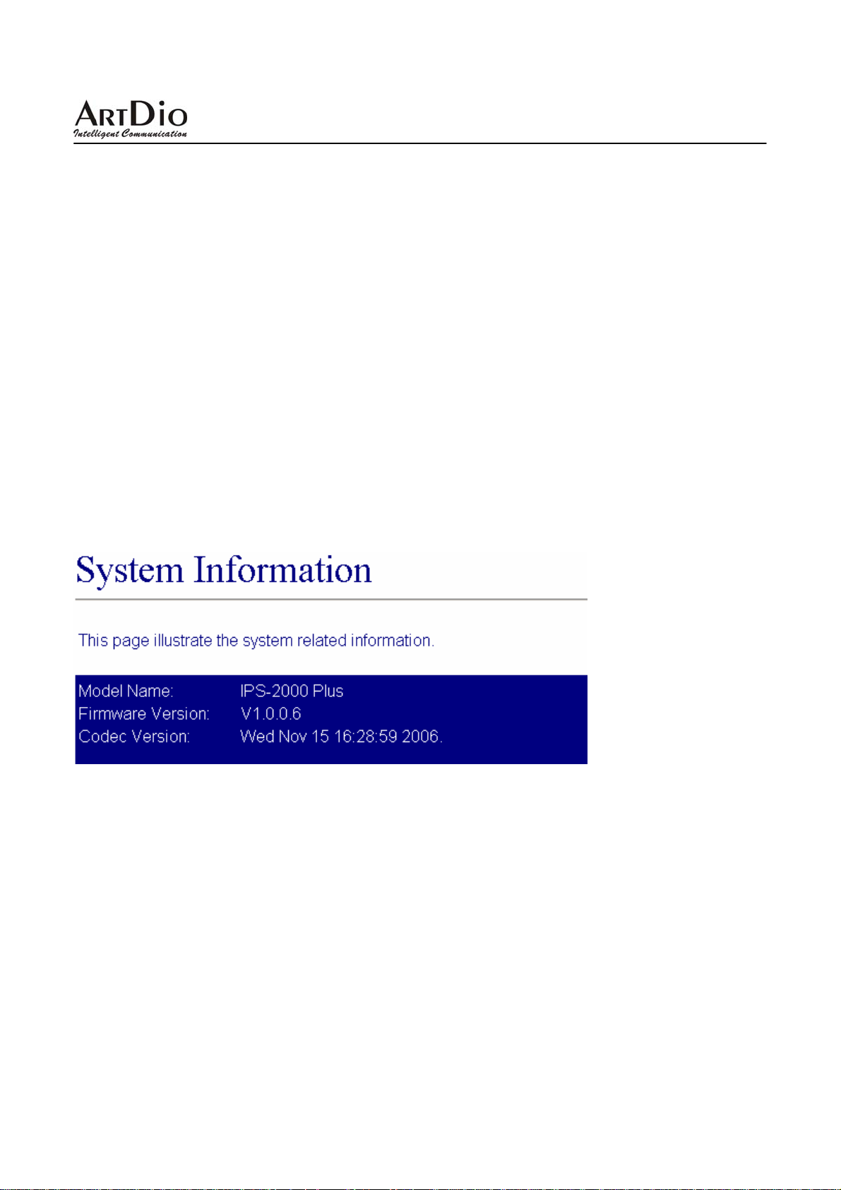
3.1 Information(系統資訊)
IPS-2000 Series 系統基本資訊,可以看到軟體的版本資訊。
Model Name 產品型號
Firmware Version Firmware 軟體的版本
Codec Version Codec 軟體的編譯日期
3.2 Phone Setting(話機設定)
3.2.1 Caller ID
設定來電顯示
58
Page 59

IPS-2000 Series User’s Manual/使用手冊
Caller ID Setting
欄位名稱 說明
Caller ID
Single Caller ID
CID Without T ime
選擇顯示帳號。設定來電顯示,有 4 項來電選擇。有基於 FSK 或 DTMF 設
定的來電顯示功能。
選擇設定是否使用單一的來電 ID。
設定選擇顯示來電時間。
3.2.2 Phone Book(電話簿)
設定電話簿功能
PHONE Book
欄位名稱 說明
Delete Selected
Delete All
Position
Name
刪除按鈕。刪除所選擇項內容。
刪除按鈕。刪除所有內容。
在填入欄裏填寫所對應的序號,隨後填入的號碼將寫到對應欄位裏。
輸入撥號代碼。
59
Page 60
IPS-2000 Series User’s Manual/使用手冊
URL
Add Phone
Reset
輸入外撥號碼或 IP 位置資料。
新增此筆資料。(可填入 140 個電話號碼)
清除已設定之資料。
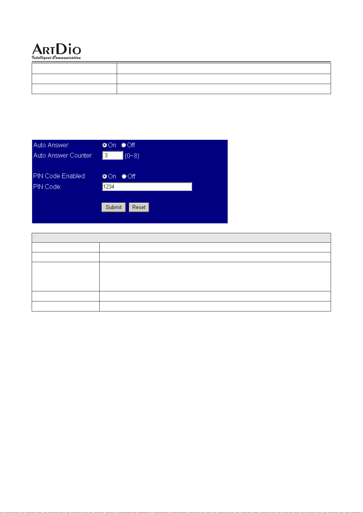
3.2.3 Auto Answer (自動應答)
設定自動應答功能
欄位名稱 說明
Auto Answer
Auto Answer
Counter
PIN Code Enabled
PIN Code
選擇使用自動語音應答。選擇開啟自動應答功能後便使用上下車功能。
自動應答時間。設定來電響鈴 X 聲後(X 為 0~8),沒人接聽則進入自動
應答。若設為
*不能與 No Answer Fwd Time Out 設定相同,否則以 call forward 優先。
設定上、下車是否使用密碼認證。
設定上、下車密碼。
0 則話機不會先響鈴,直接聽到上下車的二次撥號音。
60
Page 61
IPS-2000 Series User’s Manual/使用手冊
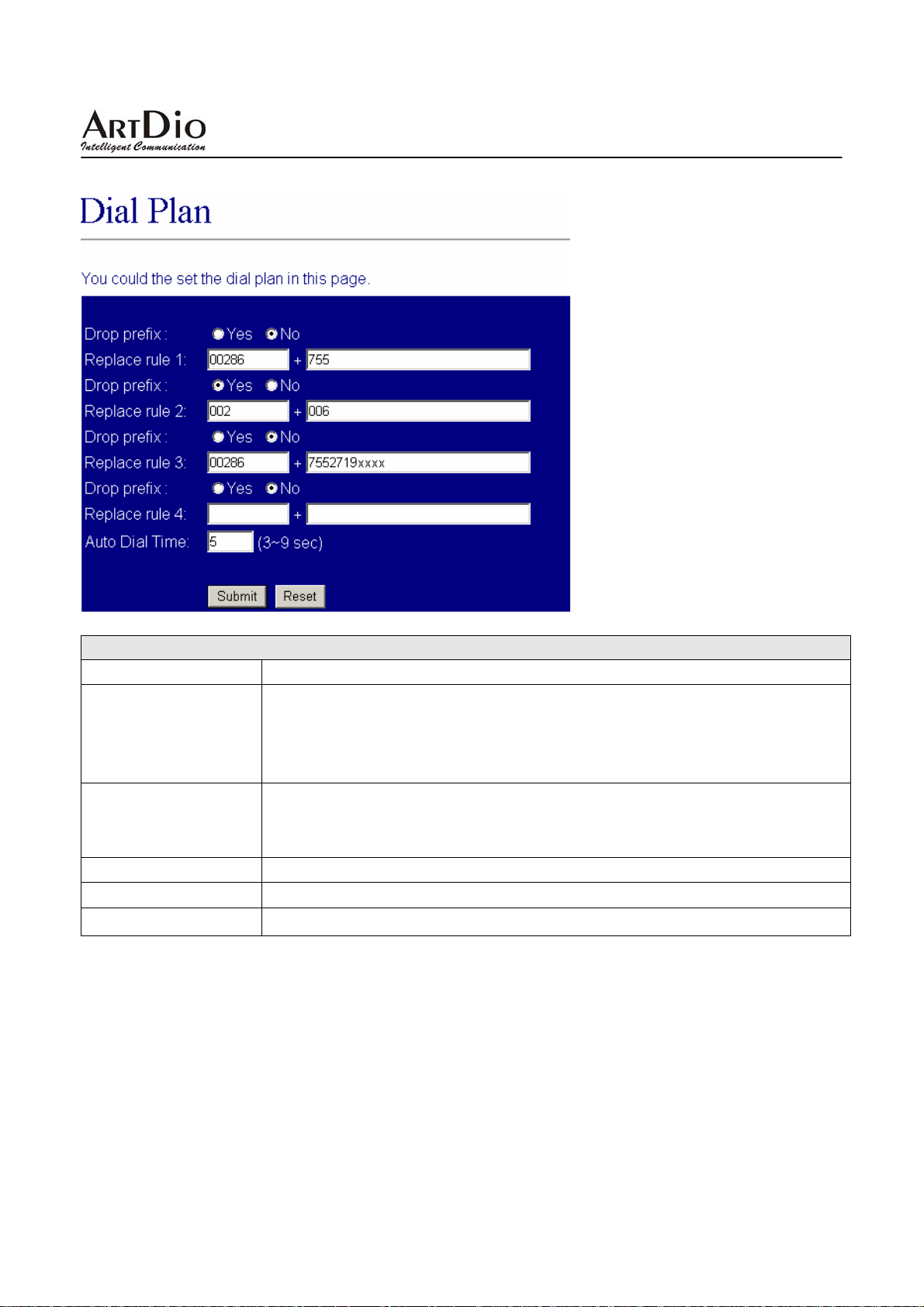
3.2.4 Dial Plan Setting(撥號規則)
Dial Plan Setting
欄位名稱 說明
Drop Prefix
Replace rule1
Auto Dial Time
Submit
Reset
預設為 No (加碼)。當設定為 Yes (減碼)時,則執行減碼的動作。
設定 4 組資料
- No (
- Yes (
設定撥號規範。
+:
xxx:
預設為 5(秒)。等待多久後自動執行撥號。
執行儲存變更設定。
清除已設定之資料。
加碼): 當 rule 符合時,則直接加碼。可輸入 7 位數。
減碼): 當 rule 符合時,則減掉符合之代碼再加碼。可輸入 39 位數。
或。
指定碼長。
61
Page 62
IPS-2000 Series User’s Manual/使用手冊
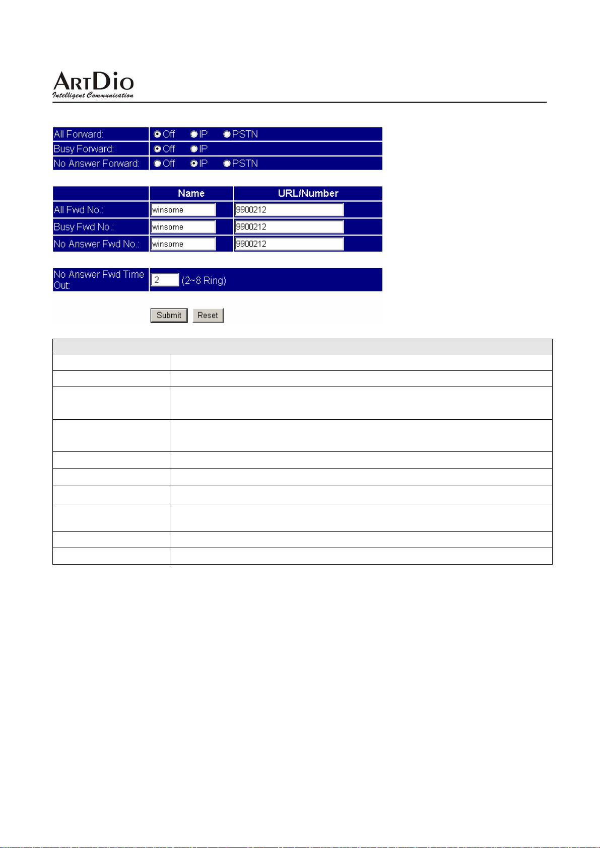
3.2.5 Forward Setting(電話轉接)
Forward Setting
欄位名稱 說明
All Forward
Busy Forward
No Answer Forward
All Fwd No
Busy Fwd No
No Answer Fwd No
No Answer Fwd Time
Out
Submit
Reset
全部轉接。打進來的所有電話都轉撥到指定號碼。
遇忙轉接。電話忙線時,啟用轉撥功能。即當電話打進來後,若電話占線,則
將轉撥到指定號碼。
無應答轉接。電話無人應答時,啟用轉撥功能。即當電話打進來後,在震鈴
逾時後
全部轉接號碼。填入開啟全部轉接後對應的轉撥姓名和電話號碼。
遇忙轉接號碼。填入開啟遇忙轉接後對應的轉撥姓名和電話號碼。
無應答轉接號碼。填入對應的無人接聽電話時轉播的姓名和電話號碼。
設定無應答響鈴時間,超過此響鈴次數,話機會進入無應答轉接狀態。
執行儲存變更設定。
清除已設定之資料。
,則將轉撥到指定號碼。
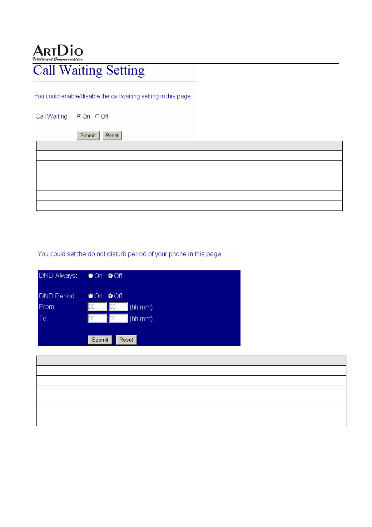
3.2.6 Call Waiting(來電等待)
設定來電等候功能
62
Page 63
IPS-2000 Series User’s Manual/使用手冊
Call Waiting
欄位名稱 說明
來電等待。設定當前話機使用來電等待功能。本機和 A 通話時,B 撥入,
Call Waiting
Submit
Reset
本機會每隔 3 秒聽到“嘟,嘟"兩聲,此時按下“HOLD”鍵來保持 A 並接
B 的電話,並且可以按“hold ”鍵在 A 和 B 之間切換通話。
聽
執行儲存變更設定。
清除已設定之資料。
3.2.7 DNS Setting(來電拒接)
設定拒接電話功能
DNS Setting
欄位名稱 說明
DND Always
DND Period
Submit
Reset
拒接所有撥入電話,選擇on後所有打入的電話將聽到忙線音,off 為不使用。
某時段拒接設定。阻止某段時間打入的電話。From 中填入開始時間,To 為
截至時間。
執行儲存變更設定。
清除已設定之資料。
63
Page 64
IPS-2000 Series User’s Manual/使用手冊
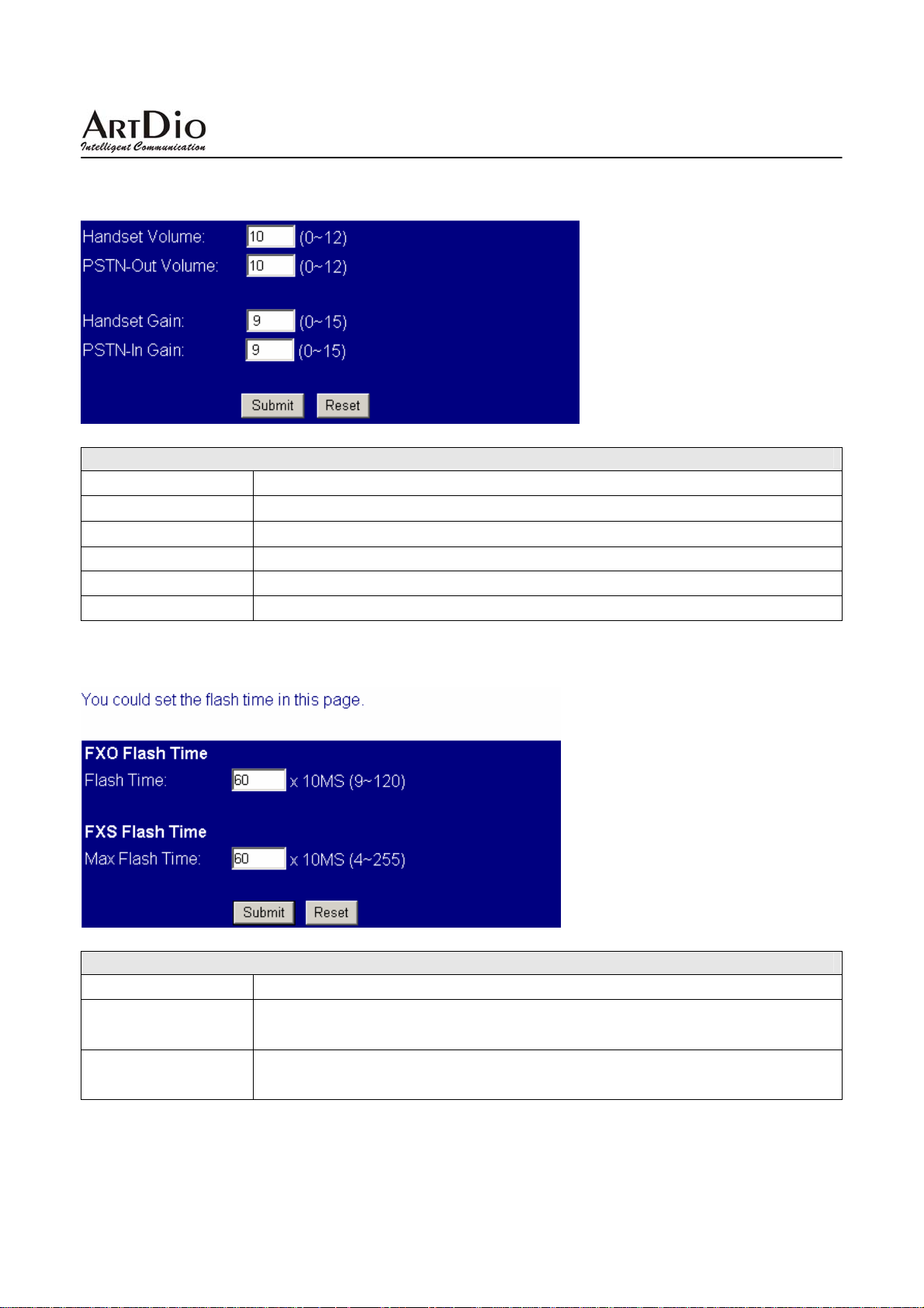
3.2.8 Volume Setting(音量設定)
設定音量大小
Volume Setting
欄位名稱 說明
Handset Volume
Ringer Volume
PSTN-Out Volume
Handset Gain
PSTN-In Gain
話筒音量。設定聽筒輸入大小
震鈴音量。設定響鈴聲大小
設定 PSTN 路線撥出時的聲音大小
設定話筒輸出大小(建議不要超過 13)
設定 PSTN 路線撥入時的聲音大小
3.2.9 Flash Time Setting(閃切設定)
Flash Time Setting
欄位名稱 說明
Flash Time
Max Flash Time
閃切設定。如使用插簧鍵來做切換鍵,設定 FXO 口插簧鍵按下到彈起的間
隔時間。
閃切設定。如使用插簧鍵來做切換鍵,設定 FXS 口插簧鍵按下到彈起的間
隔時間。
64
Page 65
IPS-2000 Series User’s Manual/使用手冊
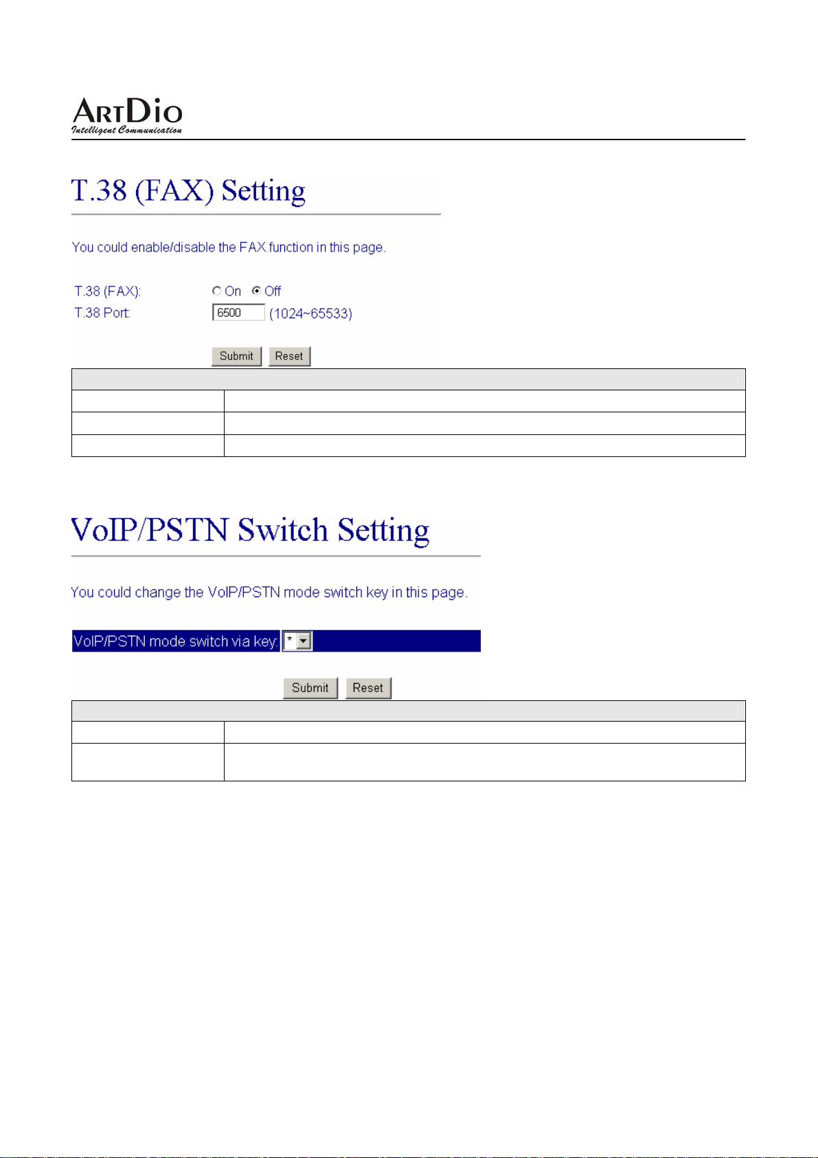
3.2.10 T.38 (FAX) Setting(傳真設定)
T.38 (FAX) Setting
欄位名稱 說明
T.38(FAX)
T.38 Port
設定網路傳真功能。On 為開啟網路傳真功能,off 為不使用。
設定傳真埠。
3.2.11 VoIP/PSTN Switch Setting(VoIP/PSTN 切換功能鍵設定)
Flash Time Setting
欄位名稱 說明
VoIP/PSTN mode
switch via key
選擇電話機的某一按鍵設定切換到 PSTN 模式狀態的按鍵。
3.3 Networking(網路)
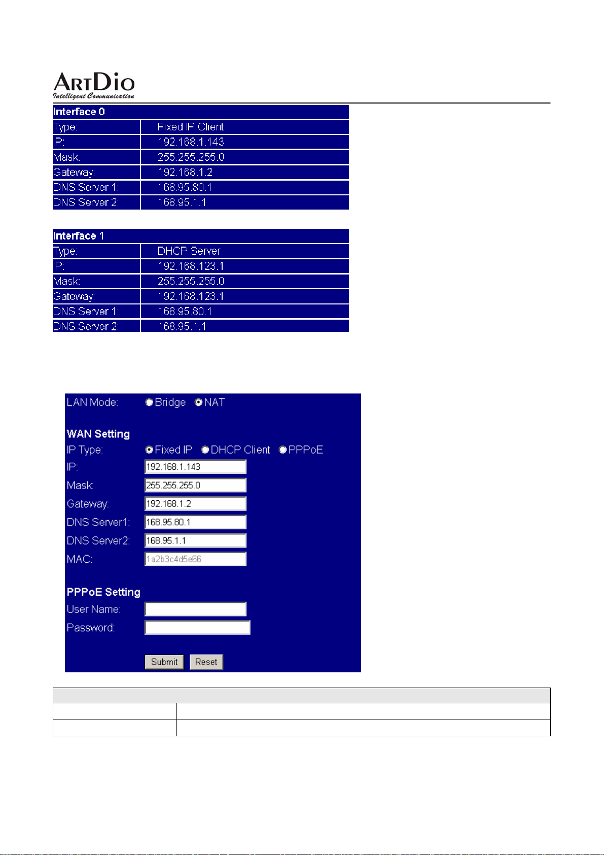
3.3.1 Status(網路狀態)
IPS-2000 Series 設備基本資訊顯示,開啟 Bridge 功能只顯示 Interface 0 資訊,開啟 NAT 功能顯示
Interface 0 和 Interface 1 資訊。
65
Page 66
IPS-2000 Series User’s Manual/使用手冊
3.3.2 Network Setting(網路設定)
設定網路環境
Network Setting
欄位名稱 說明
LAN Mode
Bridge:
開啟橋接器功能。
66
Page 67
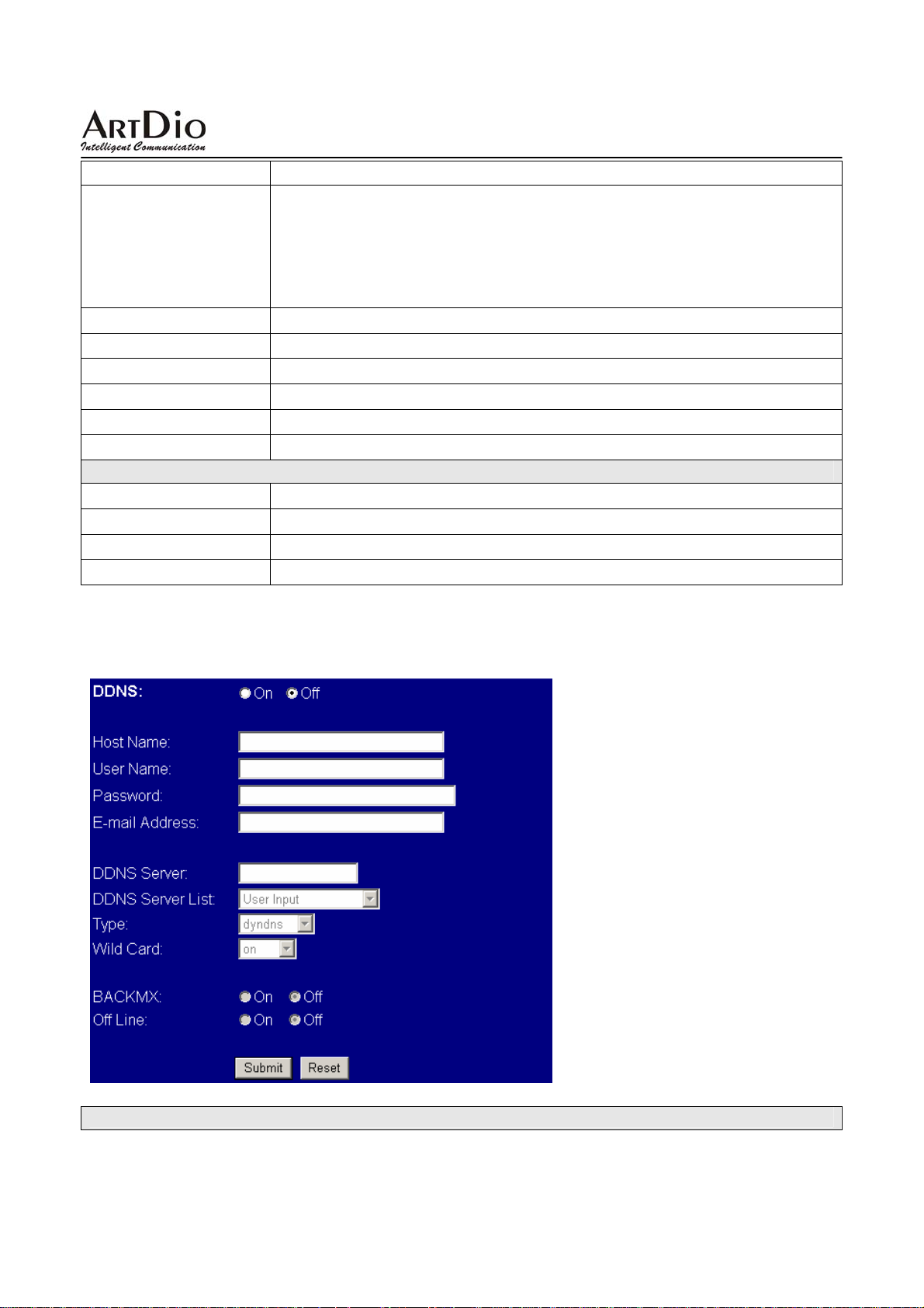
IP Type
IP
Mask
Gateway
DNS Server 1
DNS Server 2
MAC
PPPoE Setting
User Name
Password
Submit
Reset
IPS-2000 Series User’s Manual/使用手冊
NAT:開啟路由器功能
IP 類型。依實際網路環境選擇適當的網路型態:
z Fixed IP 選擇後需將 Local IP、Subnet Mask、Gateway IP、DNS 等欄
位填入相關資料。
z DHCP Client 選取後會由 DHCP server 取得相關 IP 資料。
z PPPoE ADSL 上网方式用戶選擇。
設定 WAN 的 IP 位址。
設定 WAN 的子網路遮罩位址。
設定 WAN 的預設閘道的 IP 地址。
設定 WAN 的主要 DNS 的 IP 位址。
設定 WAN 的備用 DNS 的 IP 位址。
本機網路卡號。
選取 PPPoE 時,設定用戶的 ADSL 帳戶名。
選取 PPPoE 時,設定用戶的 ADSL 帳戶的密碼。
執行儲存變更設定。
清除已設定之資料。
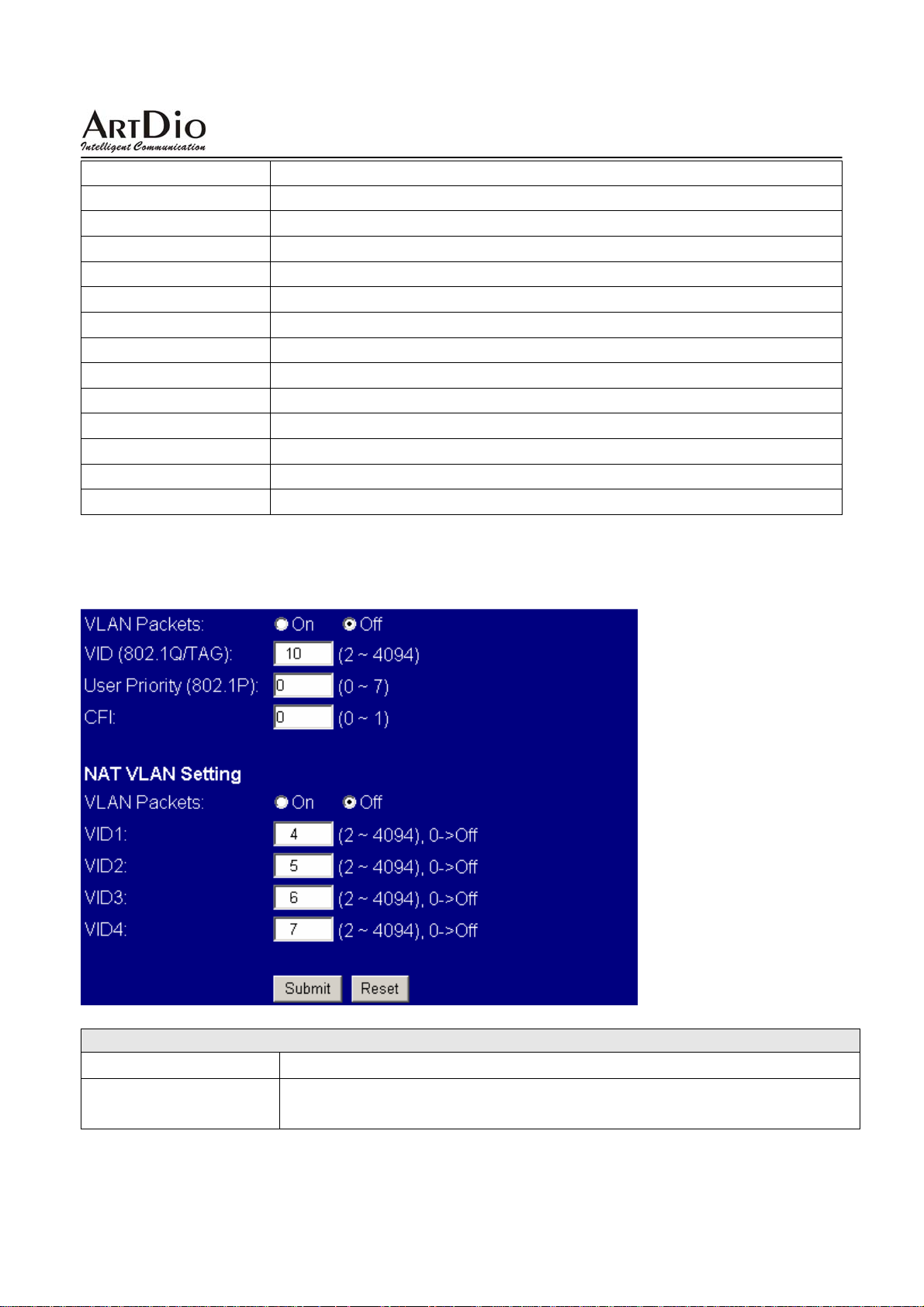
3.3.3 DDNS Setting
設定 DDNS 環境
DDNS Setting
67
Page 68
IPS-2000 Series User’s Manual/使用手冊
欄位名稱 說明
DDNS
Host Name
User Name
Password:
E-mail Address
DDNS Server
DDNS Server List
Type
Wild card
Back MX
Off Line
Submit
Reset
設定使用 DDNS。
DDNS 伺服器主機名。
DDNS 伺服器註冊帳戶。
帳戶密碼。
電子郵件位址。
DDNS 的 IP 位址或域名。
DDNS 服務提供者列表。
選擇 DDNS 工作模式。
選擇是否啟用 Wild Card 功能。
選擇是否啟用 Back MX 功能。
選擇是否啟用 DDNS 的 Off Line 功能。
執行儲存變更設定。
清除已設定之資料。
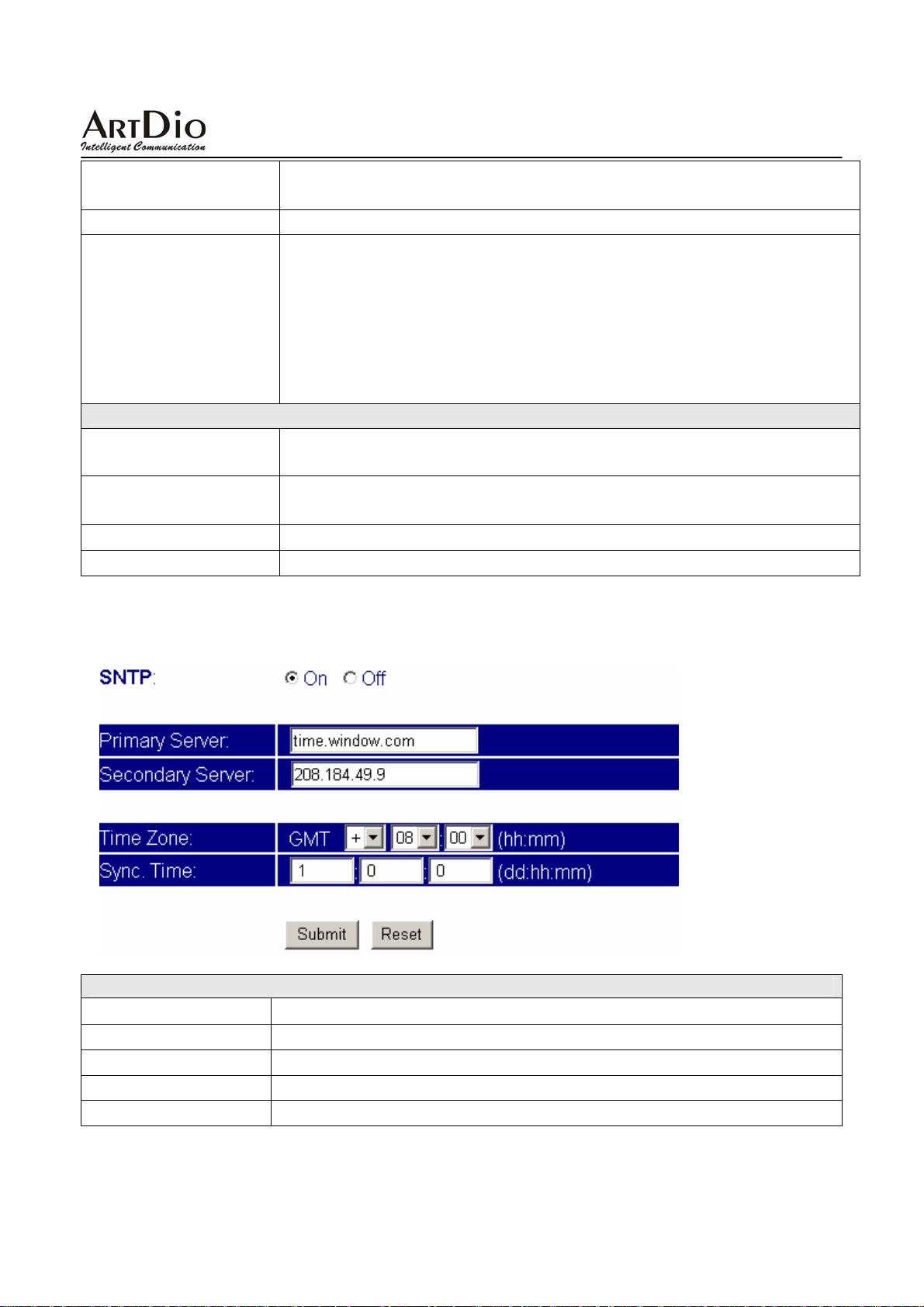
3.3.4 VLAN Setting
虛擬局域網 VLAN 之設定。
VLAN Setting
欄位名稱 說明
VLAN Packets
預設為 Off(不執行)。當設定為 On (執行)時,則啟動接收 VALN Packets 功
能。
68
Page 69
IPS-2000 Series User’s Manual/使用手冊
VID
User Priority
CFI
NAT VLAN Setting
VLAN Packets
VID1 ~ 4
Submit
Reset
預設為 136。設 定 VLAN Server 提供之虛擬區域網路識別碼 (Virtual LAN
簡稱 VLAN ID 或 VID)。
ID,
預設為 0。設定使用者優先權(user priority),優先權範圍為 0~7。
預設為 1。設定一個位元之「制式格式指示」Canonical Format Indicator
。
(CFI)
CFI = 1
資料中所攜帶的
格式」
CFI=0
是「制式格式」。
預設為 Off(不執行)。當設 定 為 On (執行)時,則啟動接收 VALN Packets 功
能。
預設為 136。設 定 VLAN Server 提供之虛擬區域網路識別碼 (Virtual LAN
ID,
執行儲存變更設定。
清除已設定之資料。
表示標籤頭中包含RIF 欄位,而且 RIF中的NCFI 旗標值決定訊框
MAC 位址是「制式格式」(Canonical Format)或「非制式
(Non-Canonical Format)。
則表示此標籤標頭不含 RIF 欄位,而且訊框中所包裝的 MAC 位址
簡稱 VLAN ID 或 VID)。
3.3.5 SNTP Setting
設定 SNTP 環境
SNTP Setting
欄位名稱 說明
SNTP
Primary Server
Secondary Server:
Time Zone
設定使用時間伺服器,on 為使用,off 不使用。
主伺服器。填寫主時間伺服器地址。
次伺服器。填寫副時間伺服器地址。
時區。填入當地時區。
69
Page 70
IPS-2000 Series User’s Manual/使用手冊
Sync. Time
Submit
Reset
自動對時週期設定。
執行儲存變更設定。
清除已設定之資料。
3.4 NAT Router(NAT 路由器設定)
此 NAT Router 功能並非所有 IPS-2000 Series 都具備。一般為依特殊需求所設計之機種才具有 NAT
Router
功能,如機型 IPS-2000N Plus 即具有此功能。
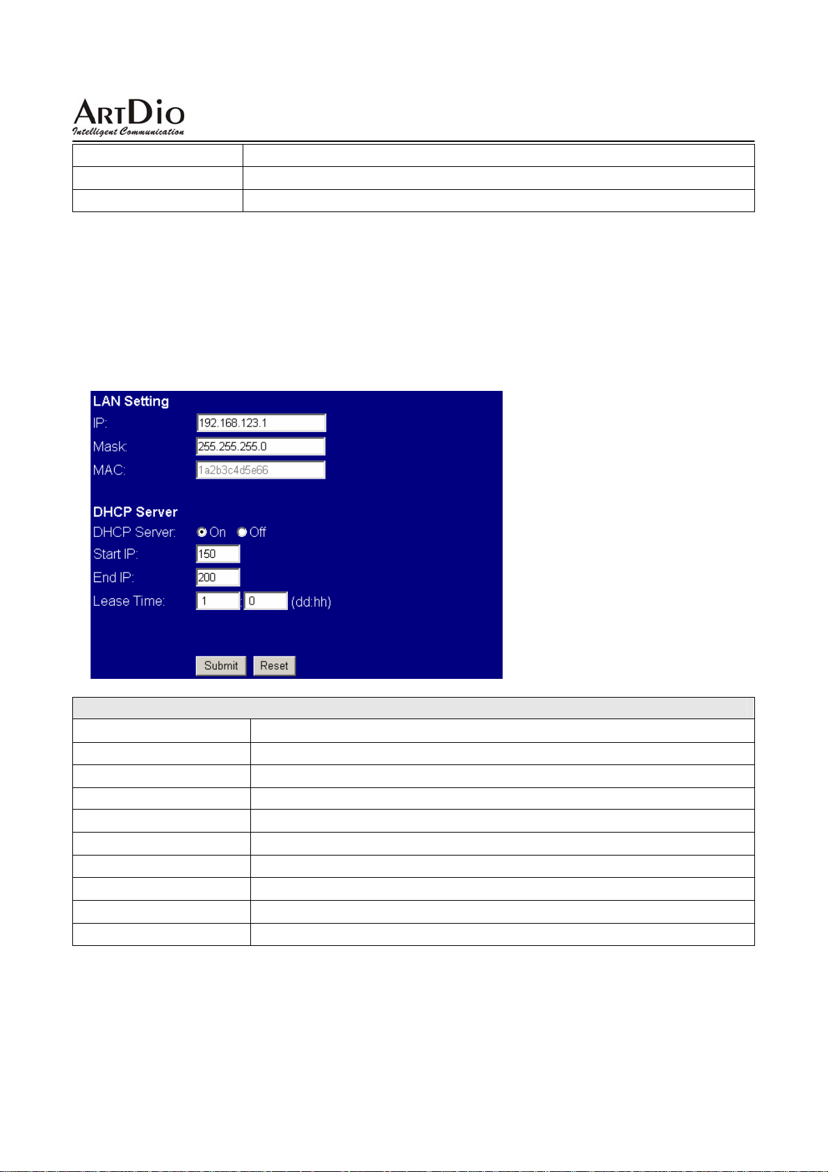
3.4.1 NAT Setting
路由器 NAT 功能之設定
LAN Setting
欄位名稱 說明
IP
Mask
MAC
DHCP Server
Start IP
End IP
Lease Time
Submit
Reset
在開啟 NAT 功能後,LAN 埠將自己成為另一個虛擬網域。
設定 LAN 端子網路遮罩。
本機網路卡號
開啟 DHCP 伺服器服務。
設定 DHCP 分配的起始 IP 其數據不能大於 255。
設定 DHCP 分配的終止 IP 其數據不能大於 255。
租約時間。由 DHCP 伺服器提供,指定 IP 位址可以使用的時間。
執行儲存變更設定。
清除已設定之資料。
70
Page 71
IPS-2000 Series User’s Manual/使用手冊
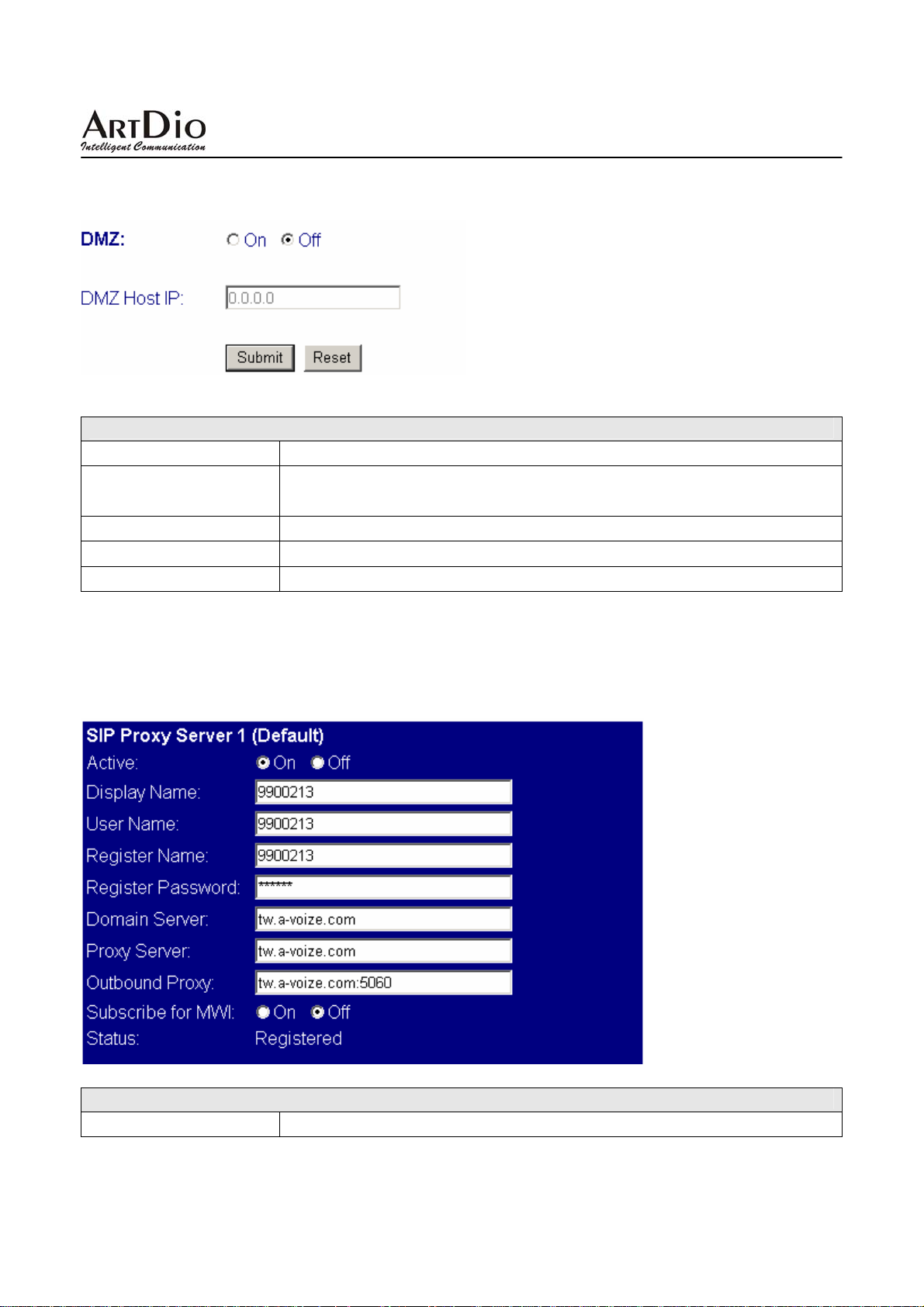
3.4.2 DMZ Setting
路由器 DMZ 功能之設定
DMZ Setting
欄位名稱 說明
DMZ
DMZ Host IP
Submit
Reset
預設為 Off(不執行)。當設定為 On (執行)時,所有的封包(除了 SIP 相關)
都會往該 IP 位置傳送。
輸入指定的 IP Address。
執行儲存變更設定。
清除已設定之資料。
3.5 SIP setting(SIP 設定)
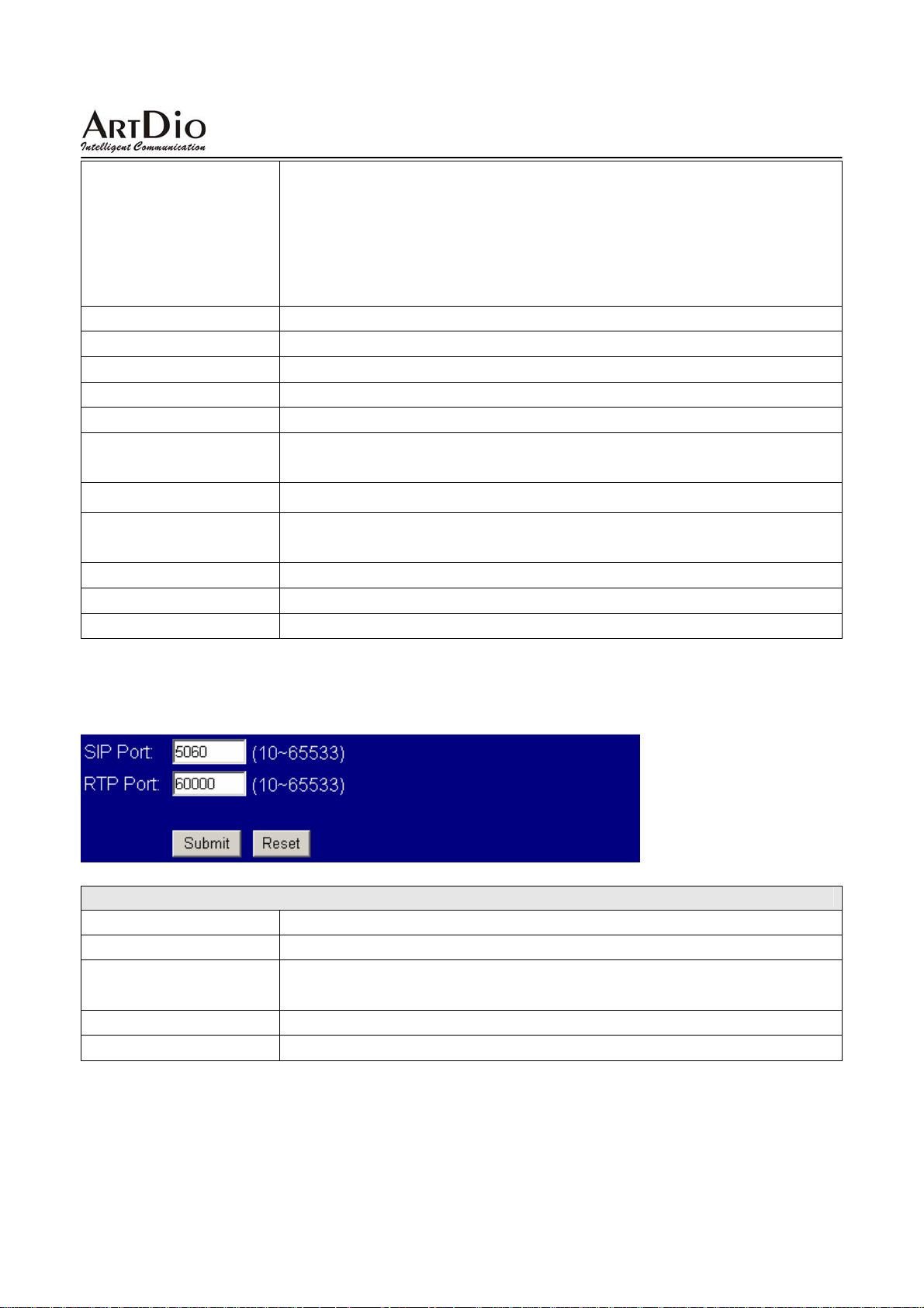
3.5.1 Service Domain(平台設定)
SIP Service Domain 功能之設定
Service Domain
欄位名稱 說明
71
Page 72
Active
Display Name
User Name
Register Name
Register Password
Domain Server
Proxy Server
Outbound Proxy
Subscribe of MWI
Status
Submit
Reset
IPS-2000 Series User’s Manual/使用手冊
帳號選擇。
z 此頁中可填入 3 個不同帳號,並且同時註冊上,當選擇 on 時為使用
當前欄
z 撥出的號碼以註冊的第一個號碼為主(以選取 on 選項的第一個選
項欄為首選
的帳號
SIP
顯示的名稱。
用戶名,使用的號碼,在此設定本話機之電話號碼。
註冊帳號名。
註冊密碼。
網域功能變數名稱。
要登錄的語音閘道器的 IP 位地址或者網域功能變數名稱。如果特殊埠
號則加
語音代理伺服器。如果特殊埠號則加 :埠號。
預設為 Off(不執行)。當設定為 On (執行)時,週期性的傳送“來話訊息
留言偵測"的動作。
註冊狀態,Registered 為註冊成功,Not Registered 為註冊失敗。
執行儲存變更設定。
清除已設定之資料。
,再在當前欄填入對應註冊帳號。
)。 第一個帳號註冊不上將自動跳轉到下一個註冊上
,撥入到註冊上的任一號碼都可以接聽到電話。
:埠號。
3.5.2 Port Setting(埠號設定)
SIP 對應 port 之設定
Port Setting
欄位名稱 說明
SIP Port
RTP Port
Submit
Reset
SIP 協定註冊埠,預設值為 5060。
RTP 埠號指語音傳送與接收的埠號。埠號可在 10-65533 的範圍內選用,
但一定為偶數。
執行儲存變更設定。
清除已設定之資料。
72
Page 73
IPS-2000 Series User’s Manual/使用手冊
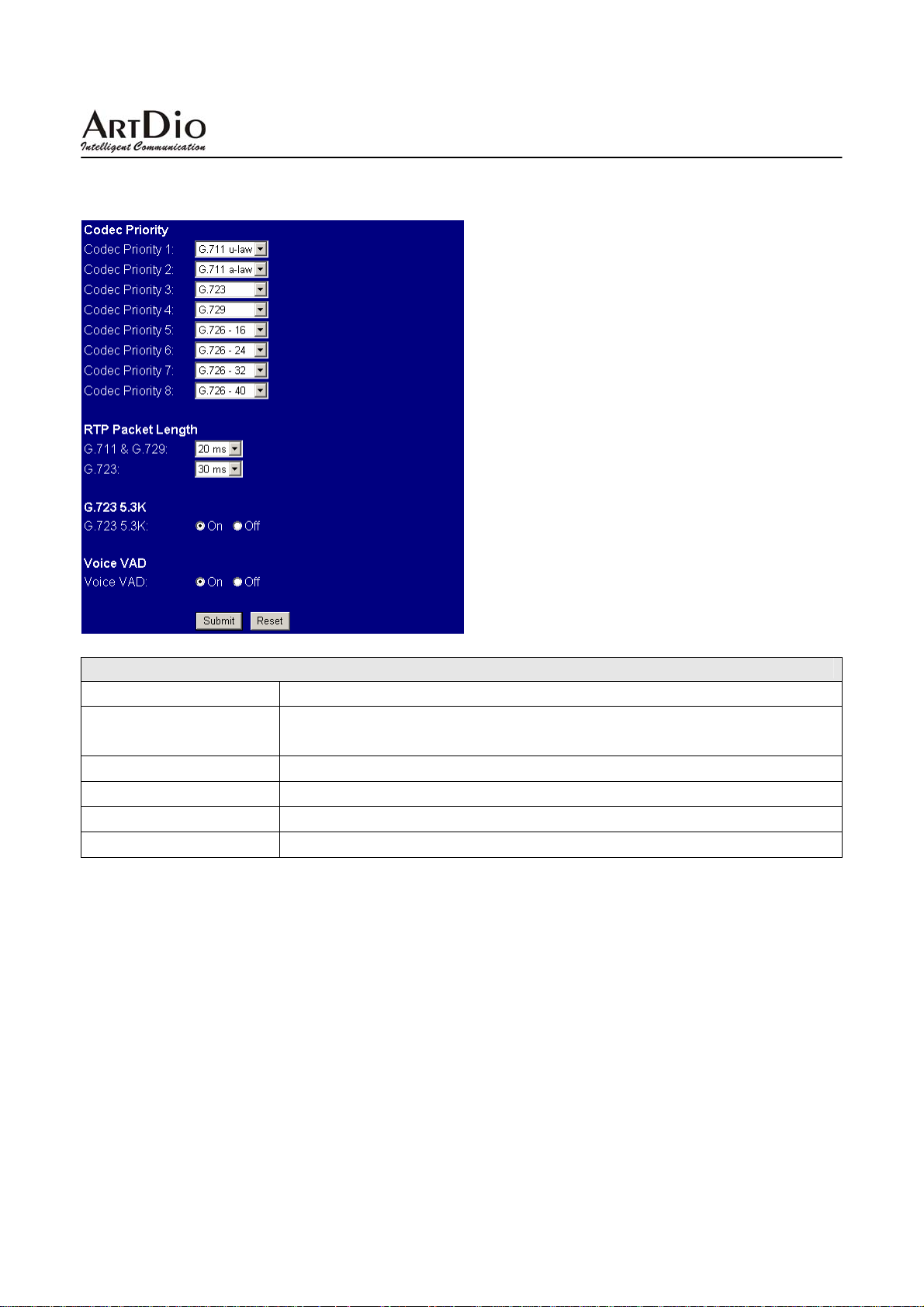
3.5.3 Codec Setting(語音編解碼設定)
語音壓縮編解碼選擇之設定
Codec Setting
欄位名稱 說明
Codec Priority
G.723 5.3K:
Voice VAD
Submit
Reset
編解碼選擇。選擇編解碼的優先權(以 Codec Priority1 為首選),及語
音編解碼格式。
使用 g.723 語音編解碼時,設定 on 為使用 5.3K/S 之 Codec。
使用動態語音檢測。
執行儲存變更設定。
清除已設定之資料。
3.5.4 Codec ID
特殊編解碼之設定
73
Page 74
IPS-2000 Series User’s Manual/使用手冊
G726 各編解碼的設定及 RFC 2833 的設定,建議使用預設值,除非註冊平臺有其他要求。
3.5.5 DTMF Setting
DTMF Setting
欄位名稱 說明
RFC2833
Inband DTMF
Send DTMF SIP Info
Submit
Reset
使用 rfc2833 方式傳送 DTMF 訊號。
使用 Inband DTMF 方式傳送 DTMF 訊號。
使用 SIP Info 方式。
執行儲存變更設定。
清除已設定之資料。
3.5.6 STUN Setting
採 STUN 方式穿越防火牆 NAT 之設定
74
Page 75
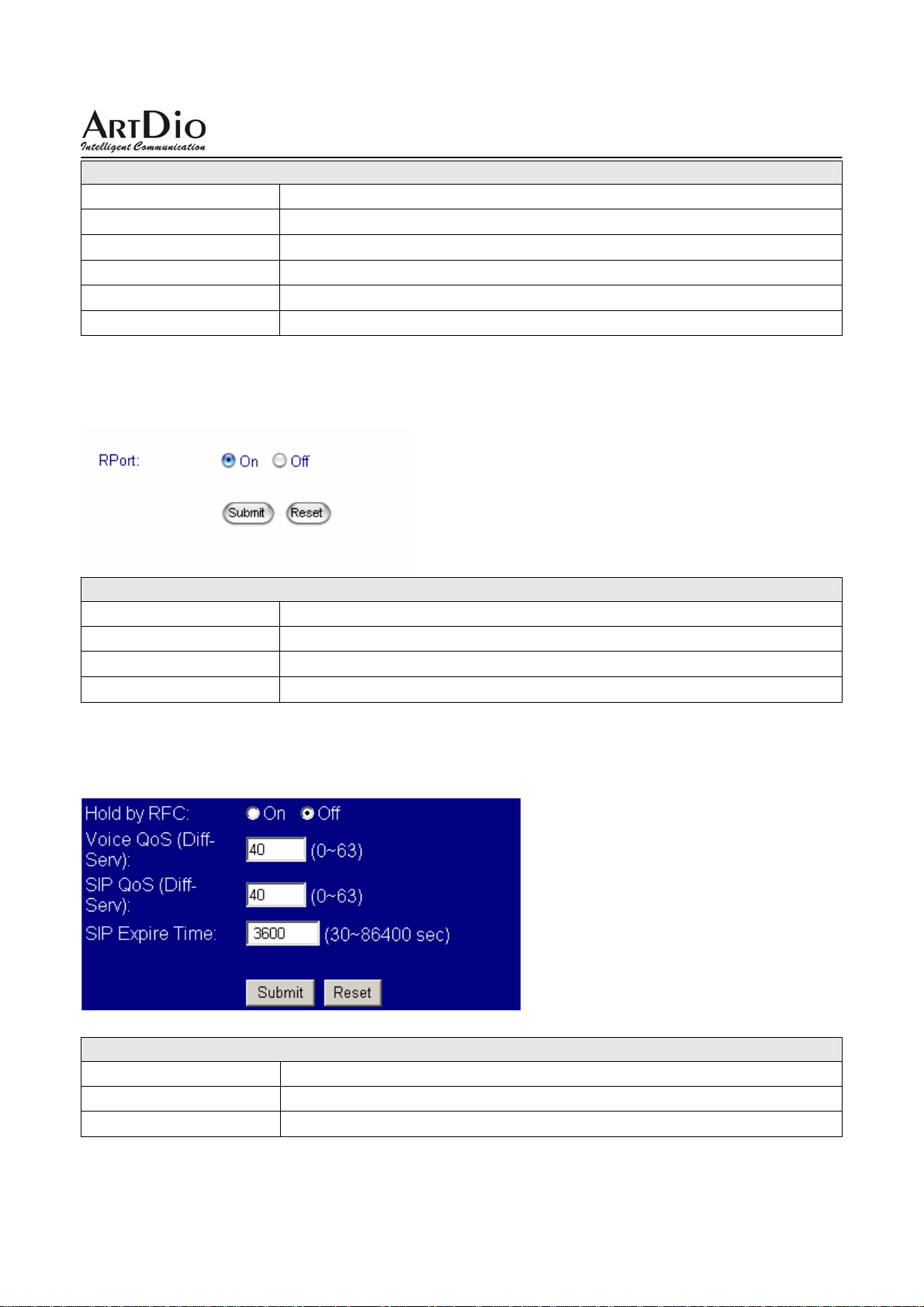
IPS-2000 Series User’s Manual/使用手冊
STUN Setting
欄位名稱 說明
STUN
STUN Server
STUN Port
Submit
Reset
設定是否使用 STUN 協定。
STUN
STUN
執行儲存變更設定。
清除已設定之資料。
3.5.7 RPort Setting
RPort Setting
欄位名稱 說明
On/Off
Submit
Reset
設定是否使用 RPort 协定。
執行儲存變更設定。
清除已設定之資料。
服務器位址。
埠號。
3.5.8 Other Setting
其他編碼相關設定功能
Ohter Setting
欄位名稱 說明
Hold by RFC
Voice QoS
RFC
設定語音包的大小,數值大的高於數值小。
選擇使用。此資訊由服務商提供。
75
Page 76
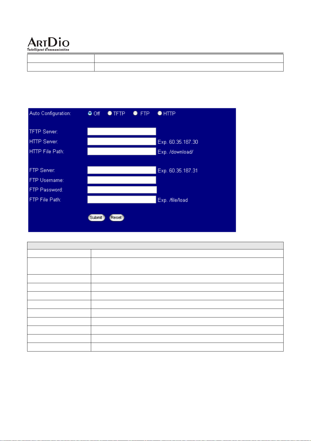
IPS-2000 Series User’s Manual/使用手冊
Sip QoS
SIP Expire Time
設定 SIP 包的大小。
SIP
註冊封包傳送間隔時間。
3.6 Others(其他設定)
3.6.1 Auto Config(自動設定)
自動更新設定功能
Auto Config
欄位名稱 說明
Auto Configuration
TFTP Server
HTTP Server
HTTP File Path
FTP Server
FTP Username
FTP Password
FTP File Path
Submit
Reset
預設為 Off(不執行)。自動更新環境設定方式,提供 TFTP,FTP 及 HTTP
等三種方式。
設定 TFTP Server 位置,可以輸入 IP 或 Domain Name 資料。
設定 HTTP Server 位置,可以輸入 IP 或 Domain Name 資料。
設定路徑名稱,例如: /123/。
設定 FTP Server 位置,可以輸入 IP 或 Domain Name 資料。
登入 FTP Server 之使用者(User name)帳號資料。
登入 FTP Server 之密碼(Password)帳號資料。
設定路徑名稱,例如: /123/。
執行儲存變更設定。
清除已設定之資料。
76
Page 77
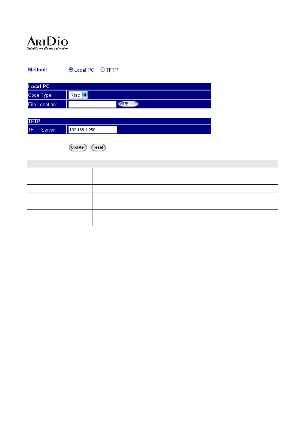
IPS-2000 Series User’s Manual/使用手冊
3.6.2 Firmware upgrade(韌體升級)
Ohter Setting
欄位名稱 說明
Method
Code T ype
File Location
TFTP Server
Submit
Reset
選擇使用 Local PC 方式或 TFTP 升級方式更新軟體。
選擇更新程式編碼類型,可選擇 Risc 和 DSP 類型。
選擇升級程式位址。
填寫升級的 tftp server 的 IP 位址。
執行儲存變更設定。
清除已設定之資料。
5.6. 3 Auto Update(自動升級韌體)
自動版本更新的功能,供提供更新 gz 或 ds 檔案格式;
77
Page 78
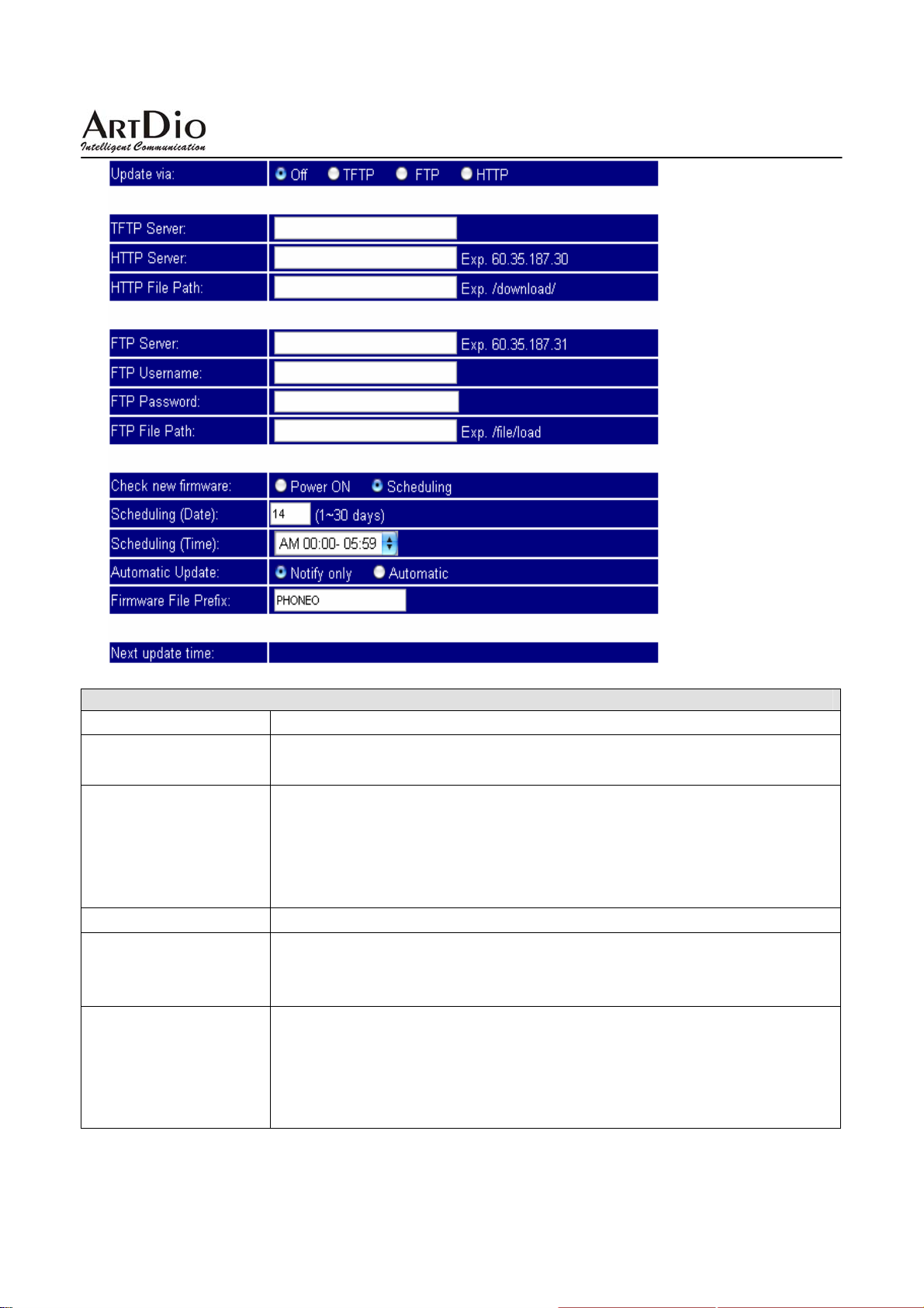
IPS-2000 Series User’s Manual/使用手冊
Auto Update
欄位名稱 說明
Update via
預設為 Off(不執行更新)。版本自動更新方式,提供 TFTP,FTP 及 HTTP
等三種方式。
Check new Firmware
預設為 Scheduling(依照時間排程)。檢查是否有新的版本提供,提供
Power ON (每次開機)或 Scheduling(按照排程)。
- Power On(
排程檢查是否有新的版本可供更新。
- Scheduling:
Scheduling (Date)
Scheduling (Time)
預設為 14 天。每隔幾天去檢查一次,提供最短為 1 天,最長為 30 天。
預設為 AM 00:00 – 05:59。每次去檢查的時間區段,詳細的時間為隨機產
生。提供四個區段分別為
12:00 – 17:59, AM 18:00 – 23:59
Automatic Update
預設為Notify only (發送訊息通知)。自動更新的方式,提供Notify only(發
送訊息通知
- Notify only:
以選擇是否更新為新的軟件。
- Automatic:
開機檢查): Power on + Scheduling,即每次開機時及依照時間
依照時間排程檢查是否有新的版本可供更新。
AM 00:00 – 05:59, AM 06:00 – 11:59, AM
。
),Automatic(自動執行更新)。
發訊息通知有新的版本,但不執行自動更新的動作,用户可
在 Scheduling 已設定的條件下自動執行版本更新的動作,
78
Page 79
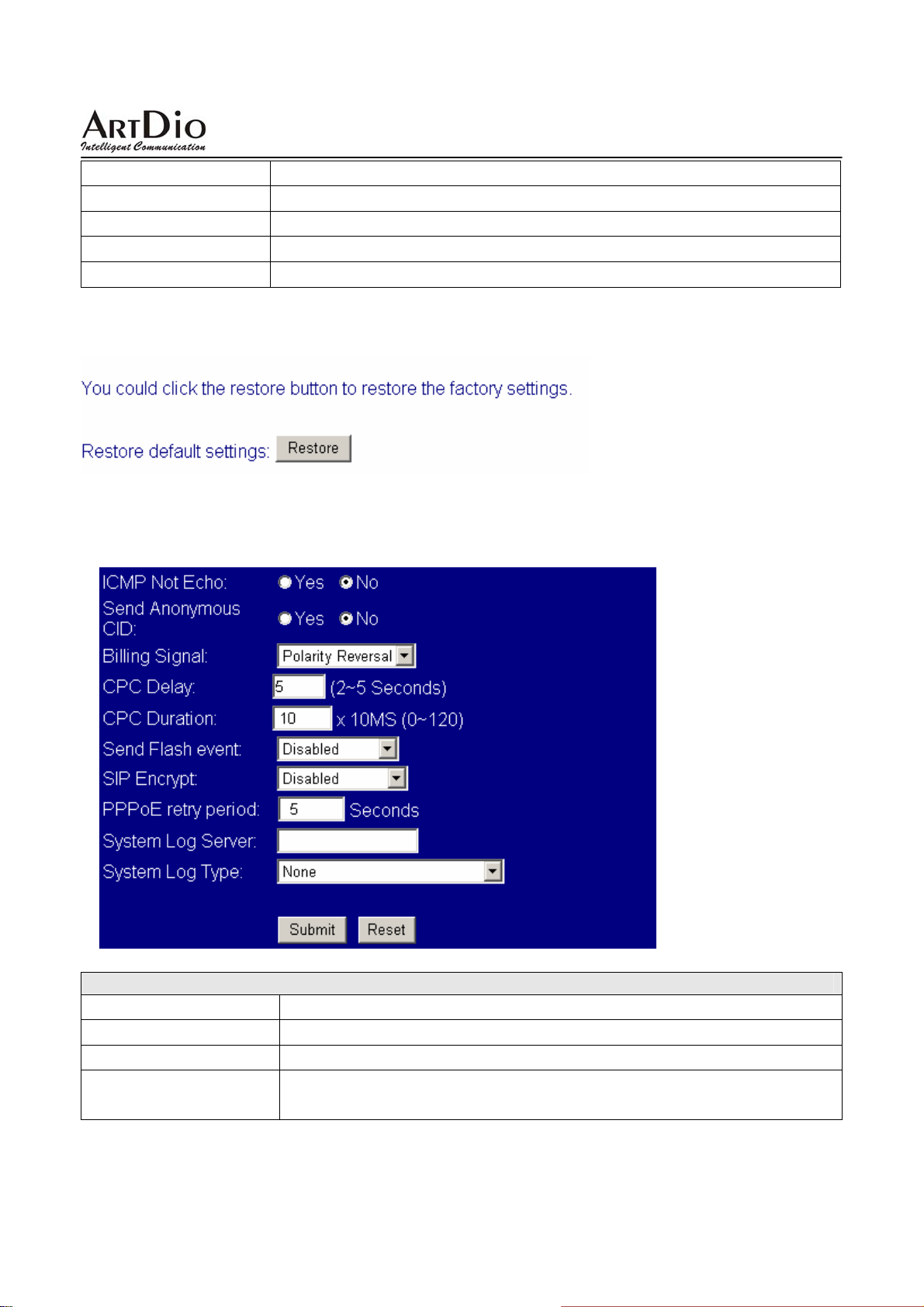
IPS-2000 Series User’s Manual/使用手冊
在 POWER ON 時需用户自己選擇是否更新為新的軟件。
Firmware File Prefix
Next upd ate time
Submit
Reset
預設為產品型號。檢查符合產品型號之版本資料。
下次檢查或更新之日期與時間資料。
執行儲存變更設定。
清除已設定之資料。
3.6.4 Default Setting(回復出廠設定值)
3.6.5 Advanced Setting(進階設定)
依地區電信設備之特性選擇適當之參數,須由經銷商或技術工程師之建議。
Advanced Setting
欄位名稱 說明
ICMP Not Echo
Send Anonymous CID
Billing Signal (*)
預設為 No (不執行)。啟動不回應 ping 的訊息。
預設為 No (不執行)。啟動去電保密功能,不送本機之號碼資料。
預設為 Disable (不執行)。啟動極性反轉功能,通知計費系統 (Polarity
Reversal, T one_12K, Tone_16K)
。支援 FXS 埠。
79
Page 80
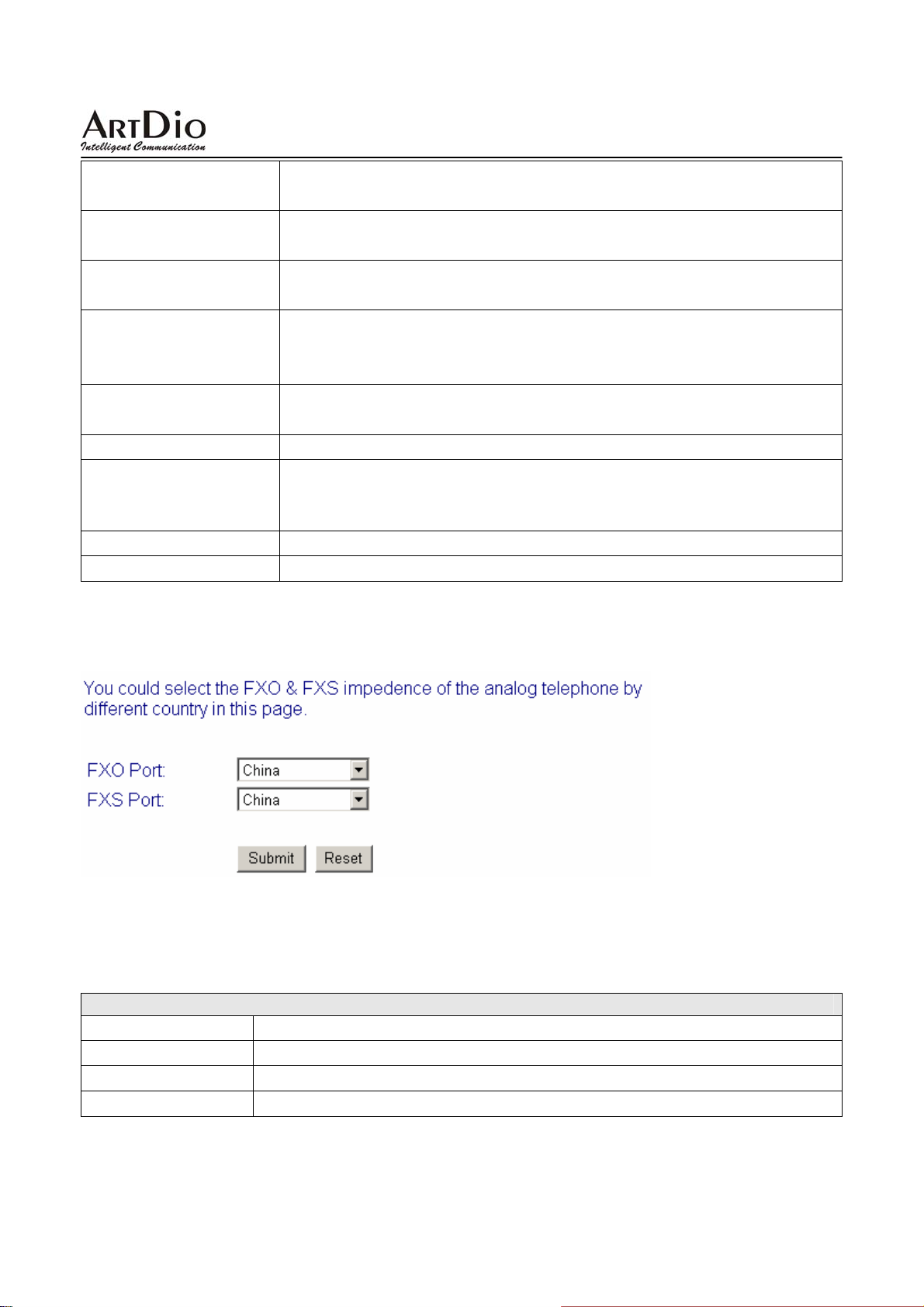
IPS-2000 Series User’s Manual/使用手冊
CPC Delay
CPC Duration
Send Flash event
SIP Encrypt
PPPoE retry period
System Log Server
System Log Type
Submit
Reset
預設為 2。提供設定當收到掛斷訊號時,等待多久時間後,開始將電壓降
到
0V。支援 FXS 埠。
預設為 0ms(不降任何的電壓)。開始將電壓降到 0V 時,要持續送多久
時間
ms。支援 FXS 埠。
預設為 Disable (不執行)。送 flash event 格式,提供 DTMF Event 及 SIP
二種格式。
Info
預設為 Disable ( 不執行)。 SIP 加密方式,提供 INFINET, AVS,
WALKERSUN1, WALKERSUN2
僅提供有此服務之環境使用。
預設為 5 Seconds。設定區間為 5~255。當 PPPoE 撥接失敗後,要等侯
多久時間再重新執行撥接功能。
提供將系統的訊息予以儲存至指定之主機位置。
預設為 None (不執行)。System Log 訊息資料格式,提供 None, Call
Statistics, General Debug, Call Statistics + General Debug, SIP Debug,
Call Statistics + SIP Debug, General Debug + SIP Debug, All
執行儲存變更設定。
清除已設定之資料。
四種格式。
七種格式。
3.6.6 FXO & FXS port(FXO/FXS 設定)
依設備所在的國家區域設定
3.6.7 System Auth
設定使用者密碼
System Auth
欄位名稱 說明
New username
New password
Confirmed password
使用者名稱。這裏設定本設備新登錄名。
設定新使用者密碼。
確認密碼。
80
Page 81

IPS-2000 Series User’s Manual/使用手冊
3.7 Save Change(儲存設定)
點擊 save 鍵後將儲存所有設定,隨後 IPS-2000 Series 將重新啟動。
3.8 Reboot(重新啟動)
重新啟動。
81
Page 82
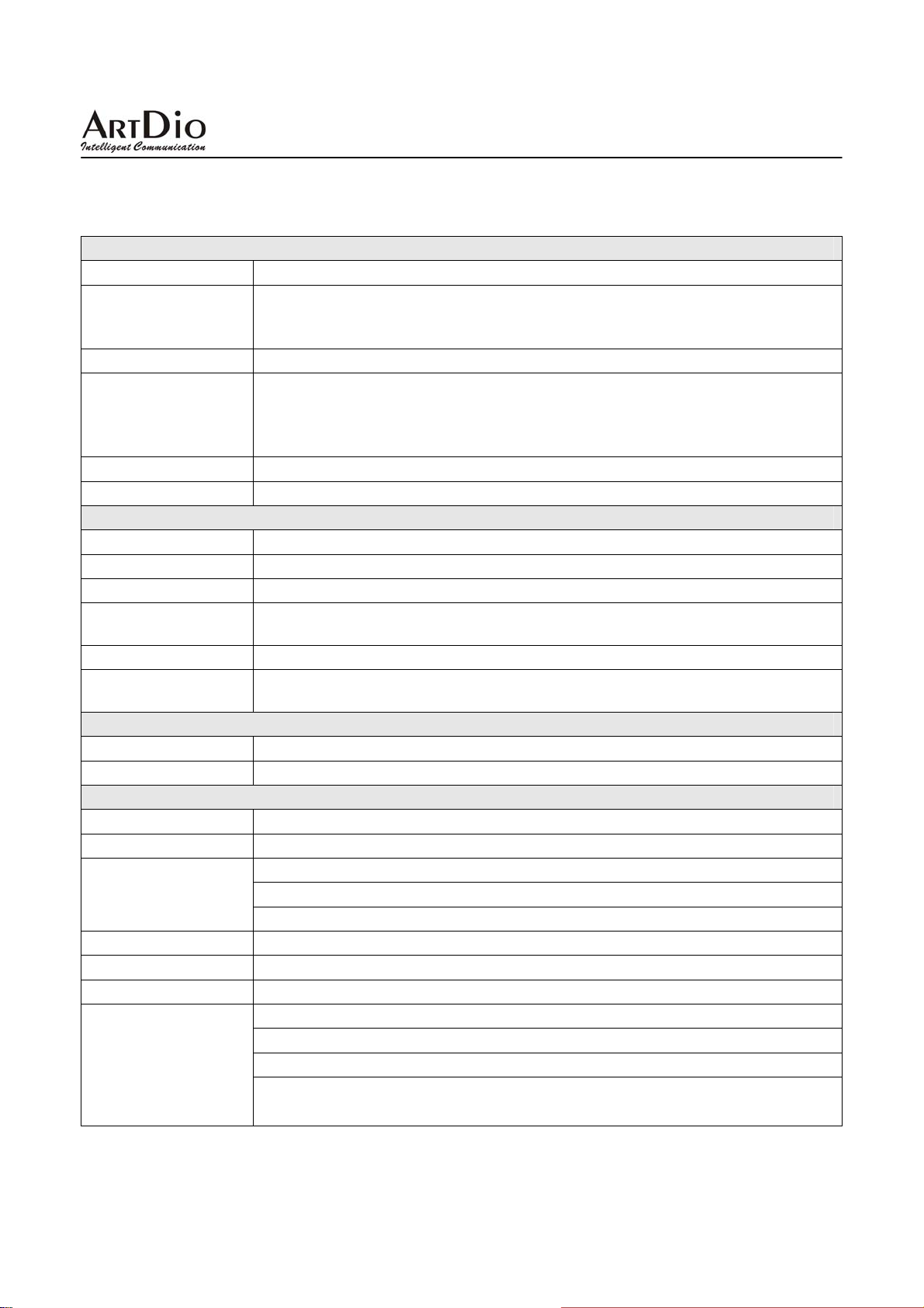
IPS-2000 Series User’s Manual/使用手冊
4. 產品規格
語音介面
呼叫控制協定
語音壓縮
延遲 (點對點)
回音抵消
通話平均流量
其他支援
區域網路介面
介面規格
介面連接器
管理工具 網頁瀏覽器
支援網路協定
韌體更新
呼叫支援
電話機介面
介面規格
介面連接器 RJ11 電話機標準介面
其他規格
電源
耗電量
工作環境
重量
認證
尺寸
其他
SIP v1 (RFC 2543), v2 (RFC 3261)
G.711 (64k bit/s, PCM), G.723.1 (6.3k / 5.3k bit/s), G.726 (16k / 24k / 32k /
40k bit/s, ADPCM), G.729A (8k bit/s, CS-ACELP), G.729B (adds VAD &
CNG to G.729)
< 100ms
Packet Loss Compensation, Adaptive Jitter Buffer, VAD (Voice activity
detection), CNG (Comfortable noise generator), AEC (Acoustic echo
canceller), G.165 (LEC, Line echo canceller), G.168 (EC, Digital network echo
canceller)
5.3K(G.723.1) ~ 64K(G.711) bps
In-Band DTMF, Out-of Band DTMF, SIP Info
10/100Mbps Fast Ethernet
RJ-45 Connector
Static IP / DHCP Client / PPPoE Client / TFTP Client / HTTP Server / DNS
Client / Telnet / SNTP / RTP / RTCP / DDNS
HTTP / TFTP / FTP
Call Hold / Call Waiting / Call Forward / Call Transfer / Calle r ID / Call Block
/ 3-way Conference
FXS/FXO port
100 – 240VAC, 50 – 60Hz, 12VDC
6W
工作溫度:0 ~ 40℃ (32° ~ 104°F)
儲存溫度:-30 ~ 65℃ (-22° ~ 149°F)
相對濕度:10 ~ 95% Non-Condensing
288g
CE / FCC
165mm * 110mm * 35mm
140 筆資料的電話薄
英文的語音提示
NAT 穿透 ( STUN / uPnP / R-Port )
網路狀況顯示、韌體更新、無應答轉接、忙線轉接、來電直接轉接、網頁
式管理設定介面等等
,LED 指示燈。
82
Page 83

IPS-2000 Series User’s Manual/使用手冊
5. 常見問題與排解(Q&A)
1.怎樣確定 IPS-2000 Series 註冊成功?
如果 IPS-2000 Series 帳號註冊成功,IPS-2000 Series 的 register 燈會亮,如果燈滅則表示註冊不成
功。IPS-2000 Series 大約在 2 分鐘內能註冊成功。
2 .接上電源後,POWER 燈能正常亮起,但 WAN(LAN2)燈不亮,這是為什麼?
這時請您檢查連接線路是否有鬆動,如果連接正常,請檢查您的網路是否正常。
3.如果停電了是否會影響正常打電話?
停電後,IPS-2000 Series 將沒有電源供應,這是 IP 路線撥入或撥出的電話將不能接通,但 PSTN 路
線的電話還能正常撥打和接聽。
4.是否支援上下車功能?
支援。上車使用方法:
z 直接從 PSTN 外線撥入,聽到數聲震鈴聲後會出現第二次撥號音,再轉撥所要撥打的電話。
z 若有設定 PIN CODE 時,在撥通後會聽到數聲震鈴聲.接著數聲急促的嘟嘟聲,此時按 Pin code#
後就會聽到第二次撥號音,再轉撥所要撥打的電話。
下車使用方法:
z 撥打 IPS-2000 Series 的 SIP 門號,聽到數聲震鈴聲後會出現第二次撥號音,再轉撥所要撥打下車
的電話。
z 若有設定 PIN CODE 時,在撥打 IPS-2000 Series 的 SIP 門號撥通後會聽到數聲震鈴聲,接著數聲
急促的嘟嘟聲,此時按 Pin code#後就會聽到第二次撥號音,再轉撥所要撥打下車的電話。
5.如何正確撥打 PSTN 電話?
當 PSTN 優先時,拿起話筒,聽到撥號音後,即可撥打 PSTN 號碼;當 IP優先時,拿起話筒,按一下切
換鍵(預設鍵為*)切換到 PSTN 電話, 聽到撥號音後,即可撥打 PSTN 號碼。
6.如何正確撥打 IP 電話?
當 PSTN 優先時,拿起話筒,按一下切換鍵(預設鍵為*)切換到 IP 電話,聽到撥號音後,即可進行
撥號。撥完號碼後按下#鍵結束(也可不按)後,撥號完畢。
7.保留(Hold)如何使用?
當正在接聽電話時,通過按一下 Hold 鍵或者插簧鍵可以保持對方,再按下一次將恢復通話。
8.如何使用來電等待(Call Waiting)?
當正在通話時,從話機聽筒傳出“嘟嘟"兩聲,表示有插撥進來, 若想接聽插撥, 可以按 HOLD
鍵或者插簧鍵,就可以接聽插撥了。
9.如何操作來電轉移 Call Transfer?
z 無條件轉移(
與 B 在通話的過程中,A 執行轉接給第三方,A 先 Hold 住與 B 的通話,按#510#接著輸入第三方的
A
號碼
,結束加"#"字鍵,即可將電話轉給第三方。
z 服務轉移(Attendant Transfer)
A
與 B 在通話的過程中,A 執行轉接給第三方,A 先 hold 住與 B 的通話,#511#接著輸入第三方的號
,結束加"#"字鍵,則第三方開始振鈴,A 與 C 通話後,A 掛斷電話,則 B 與 C 可以互相通話。
碼
Blind Transfer)
83
Page 84
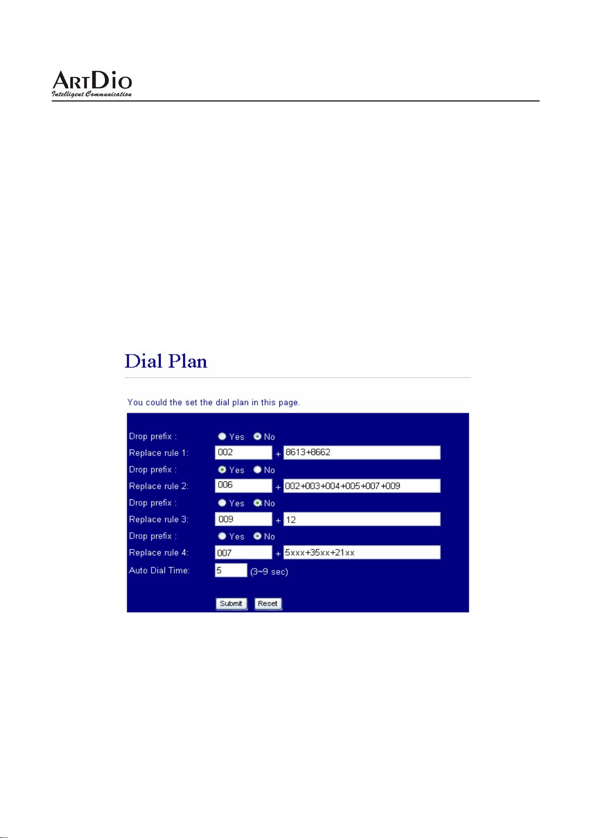
IPS-2000 Series User’s Manual/使用手冊
10.如何操作三方會議?
z 與使用者 A 建立通話。
z 通話中按下 Hold 鍵或者插簧鍵將 A 通話保留
鍵。
,再按#512#接著輸入 B 的號碼,結束加"#"字
z 接通 B 後,告知有來電並詢問接聽意願。
z 如果 B 不願意接聽,或轉接(諮詢)B 失敗,請按下 Hold 鍵或者插簧鍵取消轉接並取回與 A
之通話。
z 如果 B 願意接聽,請您按再下 hold 鍵或者插簧鍵後,進入三方會談。
11.速撥鍵(SPEED DIAL) 要怎麼用?
先在
Speed Dial 的網頁裏填入您需要快速撥號的號碼,然後拿起聽筒或者按下免持鍵後,按下*
鍵(切換到
IP 線路的電話號碼。)
IP 線路),再按下對應的快速撥號號碼,接著按下#鍵後速撥完畢。(注:只能速撥
12. IPS-2000 Series 支持什麼類型的電話機?
IPS-2000 Series 的 RJ-11 介面是國際標準,可以使用於大部分標準的電話機,包括傳統無線電話
DECT(數位先進)無線電話,所有電話的功能都能使用,其餘的功能請參考您的電話使用手冊。
和
13.Dial plan 設定範例
範例 1: Drop prefix: No, Replace rule 1: 002, 8613+8662。
說明 1:當撥號時有輸入 8613 時,只要符合 8613 開頭的號碼,全部在前面自動加上 002;則 實
際號碼為[002+8613+xxx]。
說明 2:當撥號時有輸入 8662 時,只要符合 8662 開頭的號碼,全部在前面自動加上 002;則 實
際號碼為[002+8662+xxx]。
範例 2:Drop prefix: Yes, Replace rule 2: 006, 002+003+004+005+007+009;
84
Page 85

IPS-2000 Series User’s Manual/使用手冊
說明 1:當撥號時有輸入 002 時,只要符合 002 開頭的號碼,全部將 002 開頭的號碼,置換成
006;則實際號碼為[006+xxx]。
說明 2:當撥號時有輸入 003 時,只要符合 003 開頭的號碼,全部將 003 開頭的號碼,置換成
006;則實際號碼為[006+xxx]。
範例 3:Drop prefix: No, Replace rule 3: 009, 12。
說明 1:當撥號時有輸入 12 時,只要符合 12 開頭的號碼,全部在前面自動加上 009;則實際號
碼為[009+12+xxx]。
範例 4:Drop prefix: No, Replace rule 4: 007, 5xxx+35xx+21xx。
說明 1:當撥號時有輸入 5xxx 時,要符合 5 開頭,後面接著 3 碼的資料;全部在前面自動加上
007;則實際號碼為[007+5xxx]。
說明 2:當撥號時有輸入 534 時,符合 5 開頭,後面接著 2 碼的資料;不符合加碼規則;實際號
[534]。
碼為
說明 3:當撥號時有輸入 35xx 時,要符合 35 開頭,後面接著 2 碼的資料;全部在前面自動加
上 007;則實際號碼為[007+35xx]。
說明 4:當撥號時有輸入 358822 時,符合 35 開頭,後面接 4 碼的資料;不符合加碼規則;實際
號碼為[358822]。
14. 如何多個 SIP 平台切換?
如果話機已同時設定好
2-3 個 SIP 平台帳號若要切換到想使用的平台則請照下列方法操作
例如話機同時設定有 ABC 三個 SIP 平台,A 為預設平台;要由 A 平台切換到 B 平台則
z 舉起話筒或按下免持鍵切換到 IP 撥號模式
z 按 2*
z 掛上話筒或按免持鍵保持話機待機狀態
z 現在即可以使用 B 平台撥打電話
如果要使用 C 平台則
z 舉起話筒或按下免持鍵切換到 IP 撥號模式
z 按 3*
z 掛上話筒或按免持鍵保持話機待機狀態
z 現在即可以使用 C 平臺撥打電話
如果又要使用 A 平台則
z 舉起話筒或按下免持鍵切換到 IP 撥號模式
z 按 1*
z 掛上話筒或按免持鍵保持話機待機狀態
z 現在即可以使用 A 平臺撥打電話
若話機重新啟動後則預設平台為 A 平台
85
Page 86
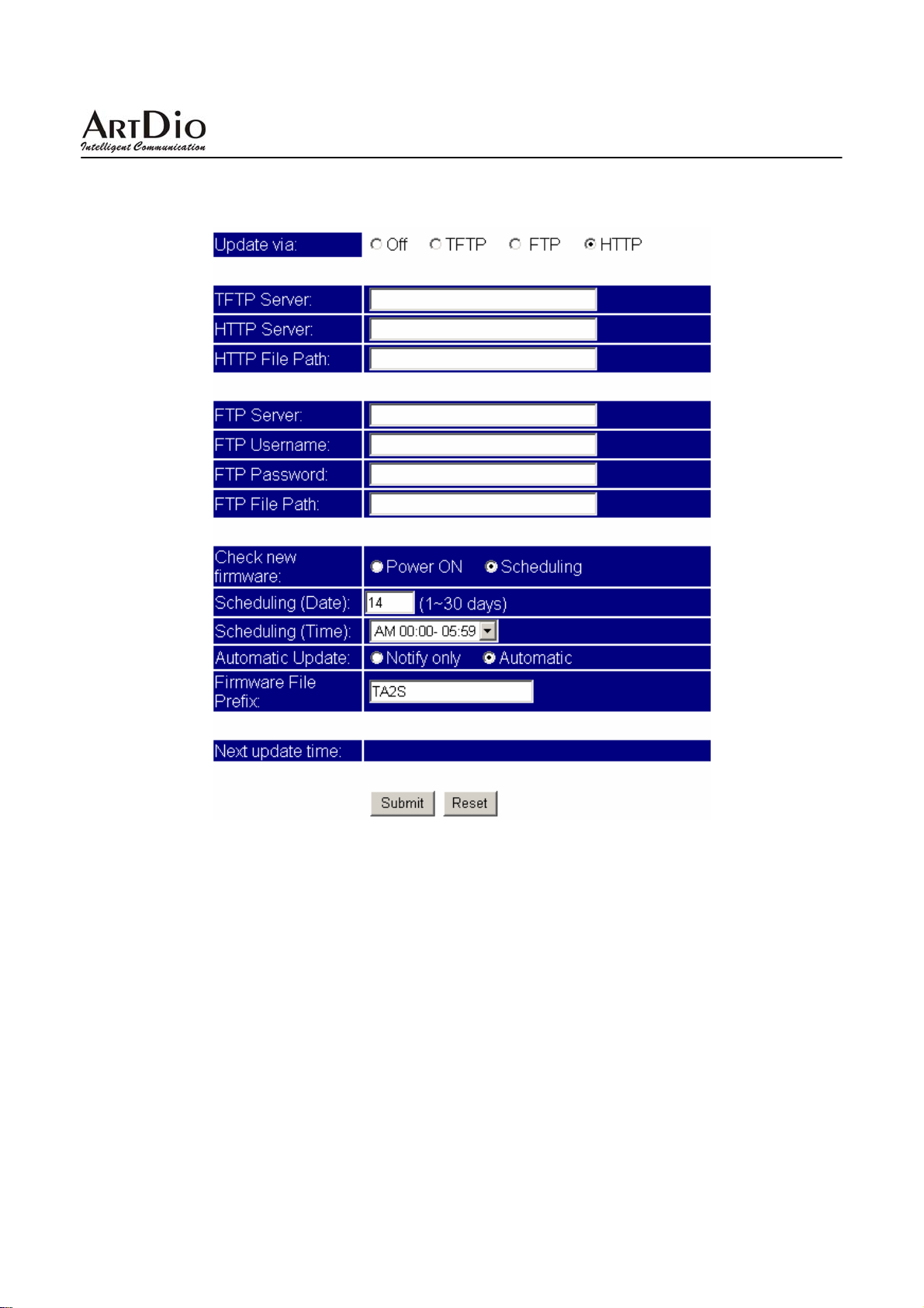
IPS-2000 Series User’s Manual/使用手冊
13. Auto Update 如何設定?
範例說明
範例 1:Update via: HTTP,Check new firmware: Scheduling,Scheduling (Date: 14),Scheduling
(Time): AM 00:00-05:59,Automatic Update: Automatic;Firmware File Prefix: TA2S。
說明 1:依照設定之行程每隔 14 天去 HTTP Server,檢查是否有可供更新之版本,如果有則自
動執行更新的動作。
說明 2:Auto Update 必須配合相應的升級伺服器: HTTP,HTTP Server: 192.168.1.50,HTTP
Path: /file/。
86
Page 87
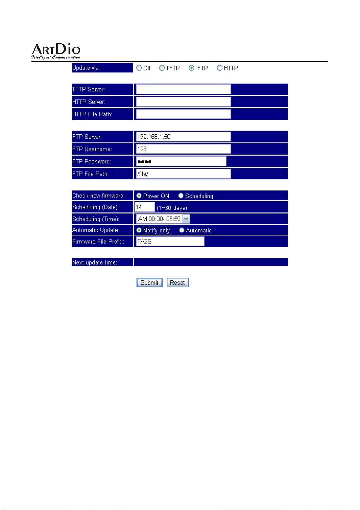
IPS-2000 Series User’s Manual/使用手冊
範例 2:Update via: FTP,Check new firmware: Power,Scheduling (Date: 30),Scheduling (Time):
AM 00:00-05:59,Automatic Update: Notify;Firmware File Prefix: TA2S。
說明 1:依照設定之行程每隔 30 天去 FTP Server,檢查是否有可供更新之版本,如果有則發出
通知的訊息,如果使用話筒當拿起電話時,會聽到 DoDoDo 三聲。如果此時要執行強制
更新的動作,請輸入“#190#”解除鎖定掛上電話,在輸入“#160#”強制執行版本更
新。
說明 2:Auto Update 必須配合相應的升級伺服器: FTP,FTP Server: 192.168.1.50,FTP File
Path: /file/。
87
Page 88

IPS-2000 Series User’s Manual/使用手冊
T aiwan Head Quarter 總公司 /
NO.476,Ming Hu Road,HsinChu 30065,Taiwan,R.O.C.
Tel: +886-3-5202121 Fax: +886-3-5202129 KINYO/
Tel: +886-3-5295000 Fax: +886-3-5295005 ARTDio/
E-mail: [email protected]
E-mail: [email protected]
http://www.kinyo.com.tw/
http://www.artdio.com.tw/
U.S.A. Branch 美國分公司 /
14235 Lomitas Avenue,La Puente,CA91746, U.S.A.
Tel:+1-626-333-3711 KINYO/
Tel:+1-626-333-0369 AR TDio/
Fax:+1-626-961-9114
Japan Branch 日本分公司 /
Kinyo Bldg,7F, 1-6-13,Kyobashi,Chuo-Ku,
Tokyo,104-0031,Japan
Tel:+81-3-3538-2272
Fax:+81-3-3538-2276
Fance Branch 法國分公司 /
Rue Freycint 77400 LAGNY sur MARNE FRANCE
Tel:+33-1-6412-4460
Fax:+33-1-6412-4461
Shanghai Branch 上海公司 /
8,775 Nong,Hang Dong Rd.,Shanghai,China
Tel:+86-21-64216757
Fax:+86-21-64206680
ShenZhen Plant 深圳工廠 /
No.5,Tianwan Road,Tianliao Village,
Gongming Town,Baoan District,ShenZhen City ,
Guangdong Province 518132,China.
SuZhou Plant 蘇州工廠 /
No.1268 jiaotong Road,Wujiang Economic
Development Zone,Wujiang City,jiangsu
215200,China
公司保有修改之權利,若有產品硬體或軟體之設計修改或改善,則以更改之後為准,
詳細軟體使用者手冊或更多的技術諮詢請登錄我們的網站下載:
http://www.artdio.com.tw/tw/support.htm
KINYO/
ARTDio/
KINYO/
ARTDio/
88
 Loading...