

Page 1
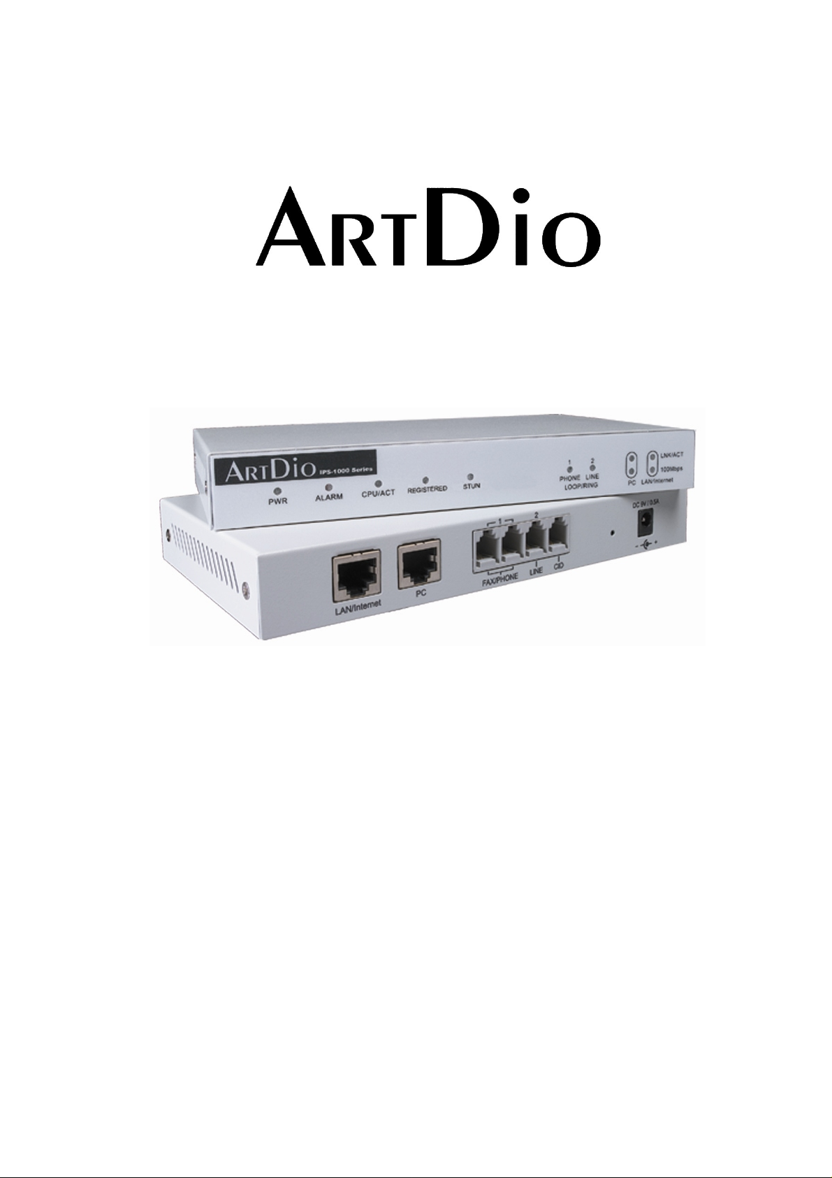
Voice Internet Phone Gateway
IPS 1000 Series
User Manual
Version:3.1 Update:2004/5/7
ARTDio Company Inc.
Page 2

IPS 1000 Series VoIP Gateway
Contents
1. Safety Instructions ............................................................................................................................4
2. Preface..............................................................................................................................................4
2.1. What is SIP........................................................................................................................4
2.1.1. Components of SIP ...................................................................................................5
3. Package Contents.............................................................................................................................7
4. Panel Descriptions............................................................................................................................7
4.1. Front Panel........................................................................................................................7
4.2. Rear Panel ........................................................................................................................8
5. LED Indicators ................................................................................................................................10
6. Connectors......................................................................................................................................11
7. IDC Connectors (Only for 1008/1016) ............................................................................................11
8. Information required before Installation...........................................................................................12
8.1. IP Address.......................................................................................................................12
8.2. SIP Information................................................................................................................13
8.3. Prepare a password for Web Management.....................................................................13
9. Installation and Configuration .........................................................................................................14
9.1. Confirming the Region ID................................................................................................14
9.1.1. Phone Setting..........................................................................................................14
9.1.2. System console settings (Only 3704/3708/3716)....................................................15
9.2. IP Address Settings.........................................................................................................15
9.2.1. Static IP Mode .........................................................................................................16
9.2.2. DHCP Mode ............................................................................................................17
9.2.3. PPPoE Mode...........................................................................................................17
10. SIP Configuration....................................................................................................................23
10.1. Channels and SIP entity..................................................................................................24
10.2. SIP Proxy and Register Parameters ...............................................................................25
10.3. SIP Entity.........................................................................................................................25
10.4. SIP Outbound Authentication..........................................................................................26
10.5. Configure STUN..............................................................................................................27
10.6. Check SIP entity Status...................................................................................................28
10.7. Phone Book.....................................................................................................................28
10.8. Make SIP Calls................................................................................................................29
10.9. Contact Address..............................................................................................................30
11. Other SIP Parameters.............................................................................................................31
11.1. Dialing Plan.....................................................................................................................31
11.2. Call Forward....................................................................................................................32
2
Page 3

IPS 1000 Series VoIP Gateway
11.3. Inbound Authentication....................................................................................................32
11.4. FAX..................................................................................................................................33
11.4.1. The devices at two sides are all IPS 1000 series gateway......................................33
11.4.2. The devices at two sides are IPS 1000 and the other brands.................................33
12. WEB MANAGEMENT INTERFACE........................................................................................34
12.1. BASIC / GENERAL .........................................................................................................35
12.2. IP SETTING ....................................................................................................................37
12.3. ADVANCED / GENERAL ................................................................................................39
12.4. SIP COMMON.................................................................................................................41
12.5. SIP OUTBOUND AUTHENTICATION.............................................................................44
12.6. SIP INBOUND ANTHENTICATION.................................................................................45
12.7. Dialing Plan.....................................................................................................................46
12.8. STUN...............................................................................................................................48
12.9. CHANNEL.......................................................................................................................49
12.10. PHONE BOOK................................................................................................................51
13. Use Private IP (Behind NAT)...................................................................................................52
14. Appendix.................................................................................................................................53
14.1. Appendix A: Phone-Set Command..................................................................................53
14.2. Appendix B: Console Command.....................................................................................55
14.3. Specifications..................................................................................................................56
14.4. Mapping table of characters used in PPPoE................................................................... 57
14.5. Region ID ........................................................................................................................58
15. Contact Information.................................................................................................................59
3
Page 4

IPS 1000 Series VoIP Gateway
1. Safety Instructions
1. Do not attempt to service the product yourself. Any servicing of this product should be referred to
qualified service personal.
2. To avoid electric shock, do not put your finger, pin, wire, or any other metal objects into vents and
gaps.
3. To avoid accidental fire or electric shock, do not twist power cord or place it under heavy objects.
4. The product should be connected to a power supply of the type described in the operating
instructions or as marked on the product.
5. To avoid hazard to children, dispose of the product’s plastic packaging carefully.
6. The phone line should always be connected to the LINE connector. It should not be connected to the
PHONE connector as it may cause damage to the product.
7. Please read all the instructions before using this product.
WARNING
2. Preface
The IPS 1000 unit is a personal SIP VoIP gateway developed using the latest in VoIP technology. It is
also very simple to install and easy to operate.
2.1. What is SIP
Session Initiation Protocol (SIP) is the Internet Engineering Task Force's (IETF's) standard for
multimedia conferencing over IP. SIP is an ASCII-based, application-layer control protocol (defined in
RFC 2543& RFC 3621) that can be used to establish, maintain, and terminate calls between two or more
end points. Like other VoIP protocols, SIP is designed to address the functions of signaling and session
management within a packet telephony network. Signaling allows call information to be carried across
network boundaries. Session management provides the ability to control the attributes of an end-to-end
call.
SIP provides the following capabilities:
Determine the location of the target end point—Supports address resolution, name mapping, and call
redirection.
Determine the media capabilities of the target end point—By using Session Description Protocol (SDP),
4
Page 5

IPS 1000 Series VoIP Gateway
SIP determines the highest level of common services between the end points. Conferences are
established using only the media capabilities that can be supported by all end points.
Determine the availability of the target end point—If a call cannot be completed because the target end
point is unavailable, SIP determines whether the called party is already on the phone or did not answer
in the allotted number of rings. It then returns a message indicating why the target end point is
unavailable.
Establish a session between the originating and target end point—If the call can be completed, SIP
establishes a session between the end points. SIP also supports mid-call changes, such as the addition
of another end point to the conference or the changing of a media characteristic or Codec.
Handle the transfer and termination of calls—SIP supports the transfer of calls from one end point to
another. During a call transfer, SIP simply establishes a session between the transferee and a new end
point (specified by the transferring party) and terminates the session between the transferee and the
transferring party. At the end of a call, SIP terminates the sessions between all parties.
2.1.1. Components of SIP
SIP is a peer-to-peer protocol. The peers in a session are called User Agents (UAs). A user agent can
function in one of the following roles:
User agent client (UAC)—A client application that initiates the SIP request.
User agent server (UAS)—A server application that contacts the user when a SIP request is received
and that returns a response on behalf of the user.
Typically, a SIP end point is capable of functioning as both a UAC and a UAS, but functions only as one
or the other per transaction. Whether the endpoint functions as a UAC or a UAS depends on the UA that
initiated the request.
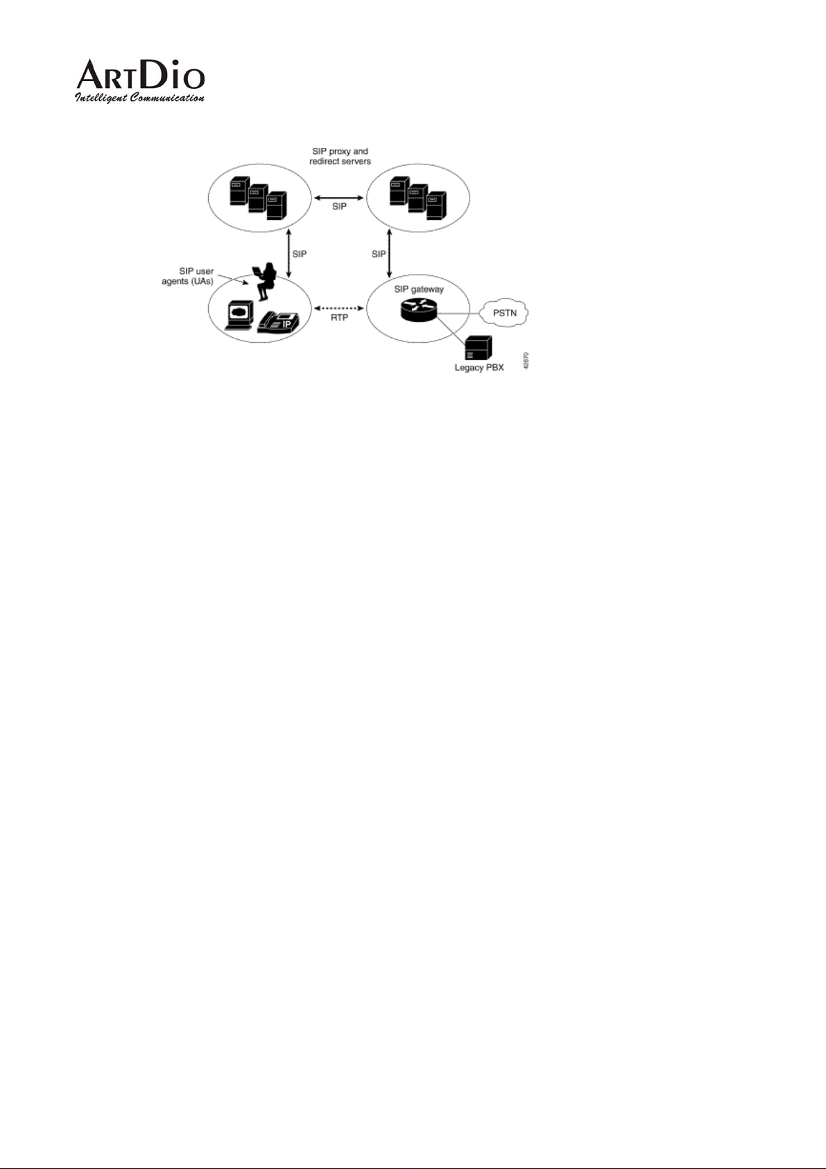
From an architecture standpoint, the physical components of a SIP network can be grouped into two
categories: clients and servers.
5
Page 6
IPS 1000 Series VoIP Gateway
Architecture
SIP Clients
SIP clients include the following:
Phones—Can act as either a UAS or UAC. Soft phones (PCs that have phone capabilities installed) and
Cisco SIP IP phones can initiate SIP requests and respond to requests.
Gateways—Provide call control. Gateways provide much functionality. The most common one is a
translation function between SIP conferencing endpoint s and other terminal types. This function includ es
translation between transmission formats and between communications procedures. In addition, the
gateway also translates between audio and video Codec and performs call setup and clearing on both
the LAN side and the switched-circuit network side.
SIP Servers
SIP servers include the following:
Proxy server—The proxy server is an intermediate device that receives SIP requests from a client and
then forwards the requests on the client's behalf. Basically, proxy servers receive SIP messages and
forward them to the next SIP server in the network. Proxy servers can provide functions such as
authentication, authorization, network access control, routing, reliable request retransmission, and
security.
Redirect server—Provides the client with information about the next hop or hops that a message should
take, then the client contacts the next hop server or UAS directly.
Registrar server—Processes requests from UACs for registration of their current location. Registrar
servers are often co-located with a redirect or proxy server.
6
Page 7
IPS 1000 Series VoIP Gateway
3. Package Contents
The IPS 1000 Gateway x 1
Power Core X 1
Accessories for fixing support X 1 (For 1008/1016)
System CD-ROM X 1
5 IDC Connector X 4 (For 1008/1016)
Rubber footer
RJ-45 Ethernet Cable X 1
RJ-1 1 Telephone Cable X 1
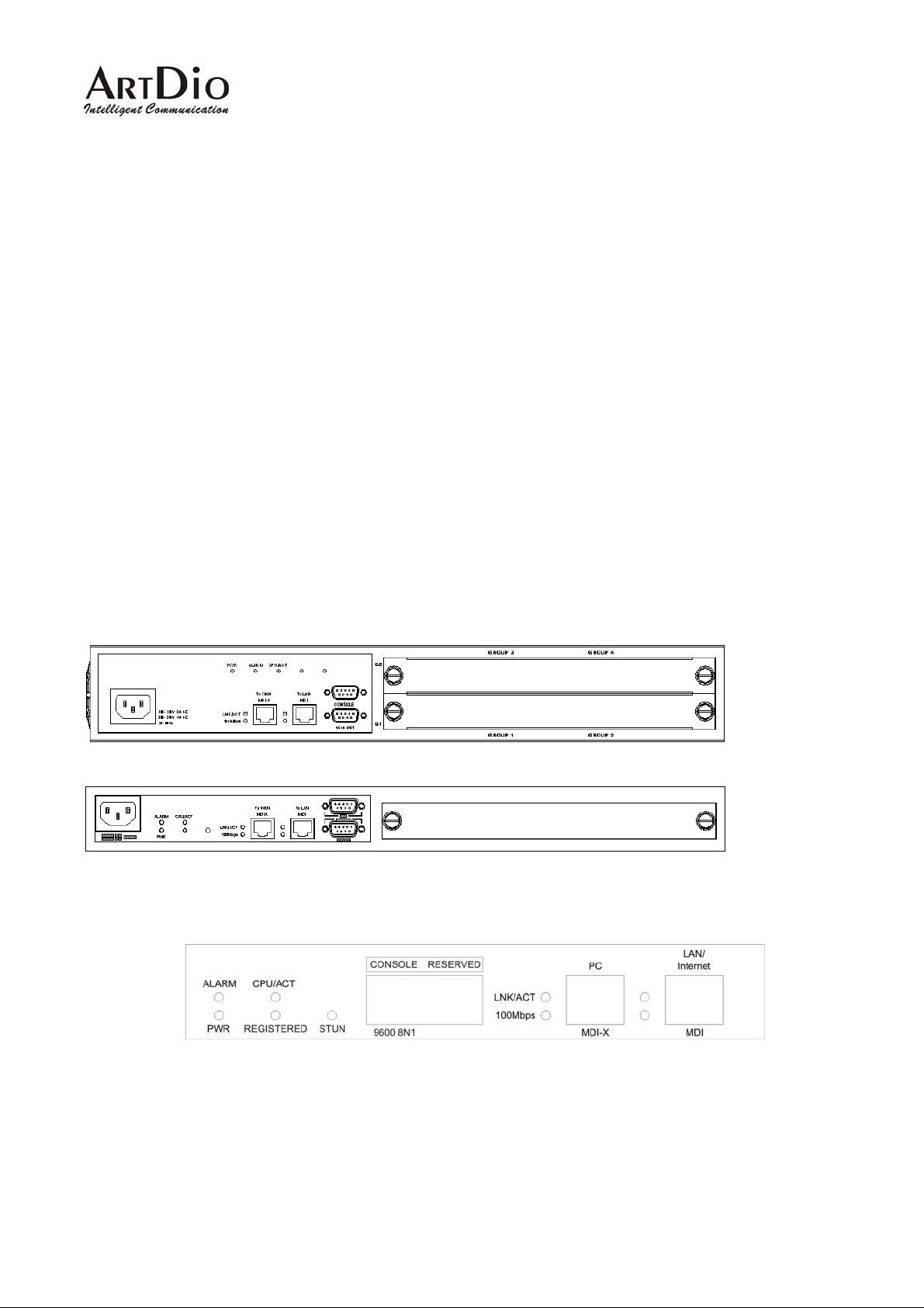
4. Panel Descriptions
4.1. Front Panel
REGISTERED STUN
REGISTERED STUN
IPS 1016 Front Panel (16 ports)
IPS 1008 Front Panel (8 ports)
IPS 1004 Front Panel (4 ports)
7
Page 8
IPS 1000 Series VoIP Gateway
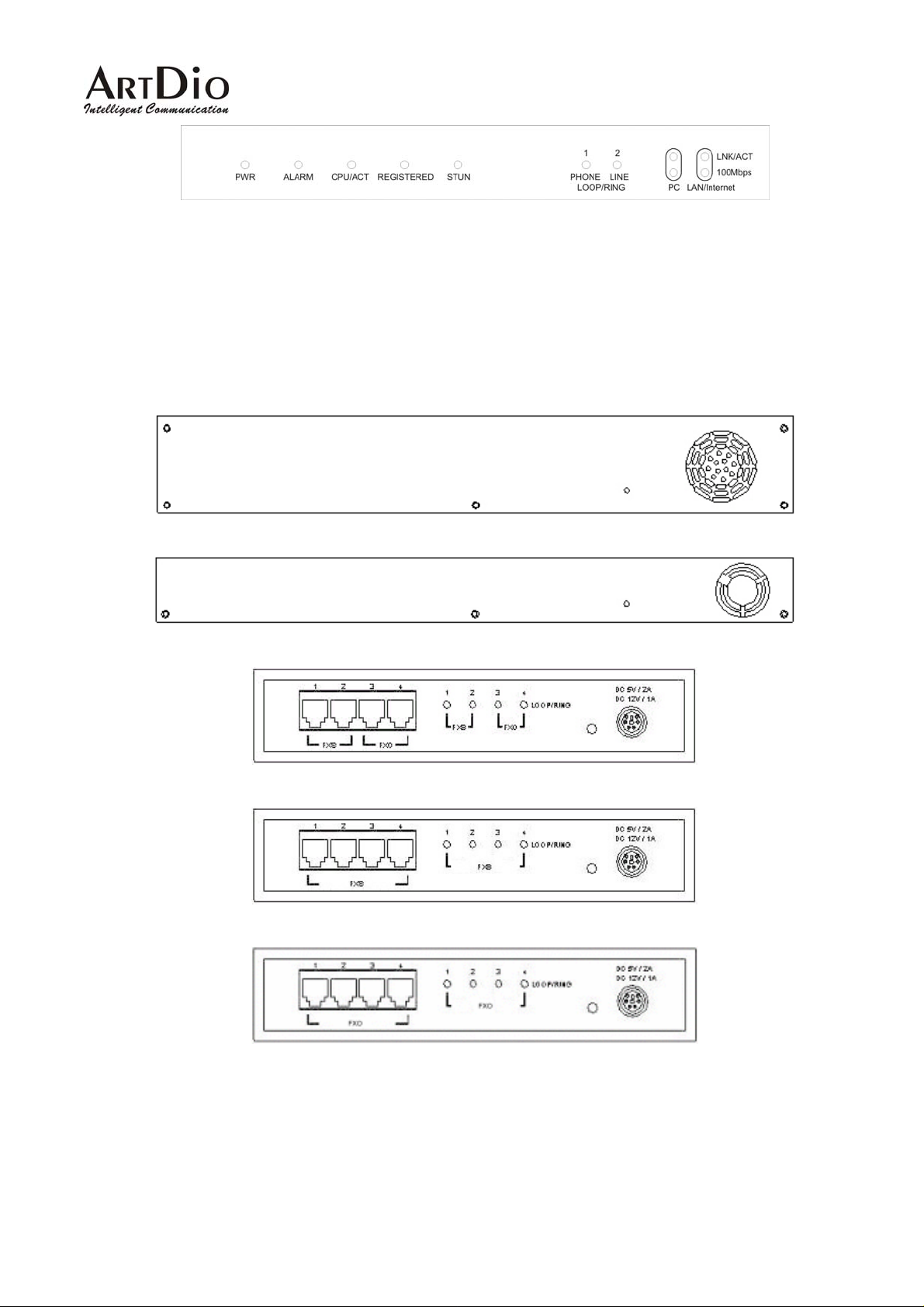
IPS 1002 Front Panel (2 ports)
4.2. Rear Panel
There is a button on the rear panel of gateway for special maintenance. Please don’t touch this button
under normal operation.
IPS 1016 Rear Panel (16 ports)
IPS 1008 Rear Panel (8 ports)
IPS 1202 Rear Panel (4 ports)
IPS 1004 Rear Panel (4 ports)
IPS 1400 Rear Panel (4 ports)
8
Page 9

IPS 1000 Series VoIP Gateway
IPS 1103 Rear Panel (4 ports)
IPS 1101 Rear Panel (2 ports)
9
Page 10

IPS 1000 Series VoIP Gateway
5. LED Indicators
LED Label Description
10/100
Ethernet
LOOP/RING
Device
LNK/ACT
100Mbps
FXS
FXO
Alarm The red light “On” indicates that system has
Power “On” indicates that the power supply is
On Link up
Off Link down
Flash Sending/Receiving
data packets
On (LNK is on) 100Mbps
Off (LNK is on) 10Mbps
On Off hook
Off On hook
Flash Ringing out
On Line is active
Off Line is inactive
Flash Ringing in
some problem; please contact your vender.
working normally.
CPU/ACT “On” indicates that the CPU is working
normally.
Registered “On” indicates that all SIP entities are
registered successful.
“Off” indicates that all SIP entities are
registered fail.
“Flash” indicates that one of these SIP
entities is registered fail.
STUN “On” indicates communicate with STUN
Server once.
“Off” indicates never communicate with
STUN Server.
10
Page 11
IPS 1000 Series VoIP Gateway
6. Connectors
Ports Label Description
Voice Ports
Ethernet
Ports
Console Port
(Only 1004/1008/1016)
FXS Connects to a telephone set or fax
machine
FXO Connects to the phone line
LAN/Internet RJ-45 connector
MDI-X connects to a Modem
PC RJ-45 connector
MDI connects to a PC
Console RJ-45 connector/RS-232 Interface
7. IDC Connectors (Only for IPS-1000 series 8/16 ports)
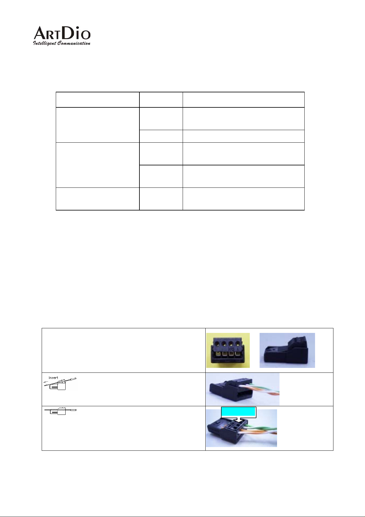
IDC connector is used for the voice interface (FXS and FXO) on the frame model. IDC connector can
easily connect PBX line and telephone wire together to the gateway. No special tools are required;
please follow the instruction to install:
(Remarks: For IDC connector, it’s better to use No. 24 wire, e.g. CAT 5)
Get the material ready
Insert the insulated wires directly into the
block for wire insertion
Push the block down until it is locked to
flush the conductor with the probe
Push from here
11
Page 12

IPS 1000 Series VoIP Gateway
Cut off the conductor outside the edge to avoid from
causing the circuit shortage
8. Information required before Installation
You need to prepare the following information before installing the gateway.
8.1. IP Address
The gateway requires an IP address for operation. Before installation you need to know how to obtain an
IP address from your local ISP. Static IP, DHCP or PPPoE can be used. The following table helps you to
decide what information you need. If your ISP offers static IP, you may need to obtain an IP from MIS
personnel in order to prevent an IP conflict. Otherwise DHCP (most cable broadband providers offer this)
and PPPoE (most ADSL broadband providers offer this) will work fine.
IP Environment Requiring information
Static IP
Public IP
Address
Private IP
Address
IP Address
Subnet Mask
Default Gateway
It is strongly suggested that you obtain an
IP address from MIS personnel in order to
prevent an IP conflict.
IP Address
Subnet Mask
Default Gateway
It is strongly suggested that you obtain an
IP address from MIS personnel in order to
prevent IP conflicts.
Your private IP requires an IP Sharing
device and you must configure the IP
Sharing device to treat the IPS unit and the
Dynamic IP address (DHCP) DHCP mode
IP that it is using as a virtual server.
12
Page 13

IPS 1000 Series VoIP Gateway
PPPoE Account Number
Password
Your ISP normally provides this information.
If you don’t have this information please
contact your ISP.
8.2. SIP Information
Before configuring SIP, the IPS 1000 requires SIP information for operation. The following table helps
you to decide what information you need.
Items Description
1. SIP Proxy If you want to make SIP calls through SIP proxy
server, you will need to know the IP address or
domain name of SIP proxy server. The proxy
server is an intermediate device that receives
SIP requests from a client and then forwards
the requests on the client's behalf. If you don’t
know which SIP proxy for setting, contact your
SIP service provider.
2. Public Address (SIP Account)
Example: [email protected]
3. Outbound Authentication You will need the information when the SIP
The public address is like phone number, you
can get the account from your SIP service
provider.
proxy server requires authentication. You can
get this authentication information from SIP
service provider when you apply for the service.
8.3. Prepare a password for Web Management
You will need to prepare a password for Web based Management. It can be a digit and/or letter
combination ranging from 1 to 6 digits (E.g. 123). For security reason, password must be set to e nter the
Web Management page.
13
Page 14

IPS 1000 Series VoIP Gateway
9. Installation and Configuration
After preparing the information you need as specified in section 5, follow the following steps to do the
basic configuration. You can use either a telephone or a system console to perform basic configurations.
It is simple to connect a telephone set to FXS port and configures the system. If you want to use system
console to configure the system (Only 1004/1008/1016 support), you have to configure your VT100
terminal to match the settings of the IPS unit’s console port. The console port’s terminal connection is
set to 9600 baud, 8 data bits, 1 stop bit and no parity. Turn on the IPS unit’s power and wait for the
terminal to display “Press Enter…” follow the directions to begin.
Here are several procedures to do:
1. Confirming the Region ID.
2. Configure IP address of gateway.
3. Enter into the WEB page.
4. Plan and configure the channels into SIP entity.
5. Configure SIP proxy and register information.
6. Configure SIP entity information.
7. Configure Outbound Authentication (If needs).
8. Configure STUN (If your gateway is behind NAT).
9. Check the SIP entity if is registered successful.
10. Configure Phone book (If needs)
11. Make a SIP call.
9.1. Confirming the Region ID
Skip this step if you are installing your IPS unit in the default region. The default Region ID is printed on
the label located outside the box. If you are installing your IPS unit at any region other then the region ID
specified on the label, you will then need to configure the IPS to the correct Region ID.
9.1.1. Phone Setting
1. Connect the power.
2. Connect the phone cable to the “Phone” socket on the rear panel as pictured above.
3. When the CPU/ACT LED is on, pick up the handset and listen for the dialing tone.
4. Dial “##0000” and listen for 3 short beep.
14
Page 15

IPS 1000 Series VoIP Gateway
5. Dial “9507#”;Assuming you are modifying for China (The last 2 digits are the regional ID)
6. Dial “971
7. Hang up the phone. The device will be updated with the new region setting after it restarts (restart
time is about 10 seconds)
#” ;Sets the new regional ID.
9.1.2. System console settings (Only for 4/8/16 ports)
SIP-RG>enable
SIP-RG #configure
Enter configuration commands, one per line. End with CNTL/Z
SIP-RG(config)#regional_id 07
SIP-RG(config)#exit
SIP-RG#delete nvram
This command resets the system with factory defaults.
All system parameters will revert to their default factory settings. All static
and dynamic addresses will be removed.
Reset system with factory defaults, [Y]es or [N]o? Yes
Attention:
Before Changing the Region ID, the system has to be reset to the default value. Therefore this step
should be done first.
The following instruction may keep the IP address unchanged after reset:
“delete nvram keep_ip”
9.2. IP Address Settings
We recommend using a traditional phone to configure the unit’s parameters, as this is the easiest way.
The following two sections contain the procedures used to configure the IPS unit according to how you
obtain your IP address (Static IP; DHCP or PPPoE).
Attention:
Every time you set a parameter item and press the “#” key to complete it, a successful setting will be
confirmed by three equal tones in succession. If your setting is unsuccessful you will be prompted with
one long tone.
15
Page 16

IPS 1000 Series VoIP Gateway
9.2.1. Static IP Mode
The following table shows an example.
IP Address 210.67.96.121
Subnet Mask 255.255.255.248
Default Gateway 210.67.96.120
Web Management Password 123
Using the information contained in the example above. The procedure is as follows:
1. Connect the IPS unit to a suitable Power source.
2. Connect a traditional phone set to the “FXS” connector located on the rear panel.
3. When the CPU/ACT light is on, pick up the phone to hear the dialing tone.
4. ##0000 ; you should hear three short tones.
5. 010
6. 02210*67*96*121
7. 03255*255*255*248
8. 04210*67*96*120
9. 15123
10. 981
11. Hang up the phone. The system should now restart.
You can also use console to configure IP address. But phone number can’t be configured by
console.(Only 1004/1008/1016)
SIP-RG>enable
SIP-RG#configure
Enter configuration commands, one per line. End with CNTL/Z
SIP-RG(config)#ip state user
SIP-RG(config)#ip address 210.67.96.121 255.255.255.248
System need to restart
SIP-RG(config)#ip default-gateway 210.67.96.120
# ; the digit “0” is used to enable “manual” IP mode.
# ; IP address.
# ; Subnet Mask.
# ; Default Gateway.
# ; “123” is the web management password.
# ; Warm-restarts.
SIP-RG(config)#exit
SIP-RG#restart
This command resets the system. System will restart operation code agent.
Reset system, [Y]es or [N]o? Yes
16
Page 17

IPS 1000 Series VoIP Gateway
9.2.2. DHCP Mode
1. Connect the IPS unit to a suitable Power source.
2. Connect a traditional phone set to the “FXS” connector located on the rear panel.
3. When the CPU/ACT light is on, pick up the phone to hear the dialing tone.
4. ##0000 ; you should hear three short tones.
5. 011
6. 15123
7. 981
8. Hang up the phone. The system should now restart.
You can also use console to configure IP address. But phone number can’t be configured by
console.(Only for 4 ports gateway)
SIP-RG>enable
SIP-RG#configure
Enter configuration commands, one per line. End with CNTL/Z
SIP-RG(config)#ip state dhcp
SIP-RG(config)#exit
SIP-RG#restart
This command resets the system. System will restart operation code agent.
Reset system, [Y]es or [N]o? Yes
# ; the digit “1” is used to enable “DHCP” IP mode.
# ; “123” is the web management password.
# ; Warm-restarts.
9.2.3. PPPoE Mode
If your network environment is using PPPoE, you need to prepare the information as specified in section
8. Information required before Installation.
The following table shows an example.
PPPoE Account [email protected]
PPPoE Password 123ab
Web management password 123
There are three ways to configure user name and password of PPPoE
1. Use phone set to configure:
You can configure the user name and password by using phone set. The command ‘09’ is used for
username and ‘10’ is for password of PPPoE. Since the user name and password use characters and
17
Page 18

IPS 1000 Series VoIP Gateway
digits are accepted by phoneset only, you need a mapping between characters and digits. You can find
them at section 14.4 Mapping table of characters used in PPPoE.
Example user name:[email protected],Password:123ab,The procedure is below
1. Connect the phone to IPS
2. When CPU/ACT is light, pick up the phone
and press
3. ##0000
4. 0938333732314068696*465742*46*46574#
5. 103132336162#
6. 981#
;You will hear 3 short tones.
;Set user name:[email protected]
;Set password is 123ab
;Save and restart.
2. Use Console to configure (Only for 4/8/16 ports Gateway)
SIP-RG>enable
SIP-RG#configure
Enter configuration commands, one per line. End with CNTL/Z
SIP-RG(config)#pppoe username [email protected]
SIP-RG(config)#pppoe password 123ab
SIP-RG(config)#exit
SIP-RG#restart
This command resets the system. System will restart operation code agent.
Reset system, [Y]es or [N]o? Yes
3. Use WEB Interface to configure:
You can configure the user name and password by using WEB interface. Follow the steps to finish
configuration.
Step 1: Using a traditional phone set to configure the web management password and phone number
You will need to use a web browser to perform the PPPoE settings through the IPS unit’s web based
management interface. To enter the web based management interface you must have a previously
configured password. Follow the next procedure to setup your password and phone number.
1. Connect the IPS unit to a suitable Power source.
2. Connect a traditional phone set to the “Phone” connector located on the rear panel.
3. When the CPU/ACT light is on, pick up the phone. You should hear the dialing tone.
4. ##0000 ; you should hear three short tones.
5. 15123
; “123” is the web management password.
6. 010# ; “0” is to enable “manual” IP mode.
18
Page 19
IPS 1000 Series VoIP Gateway
7. 02192*168*0*2# ; IP address.
8. 03255*255*255*0# ; Subnet Mask .
9. 981
# ; Used to restart the IPS unit.
10. Hang up the phone to complete the configuration.
Step 2:Configure IP address of PC
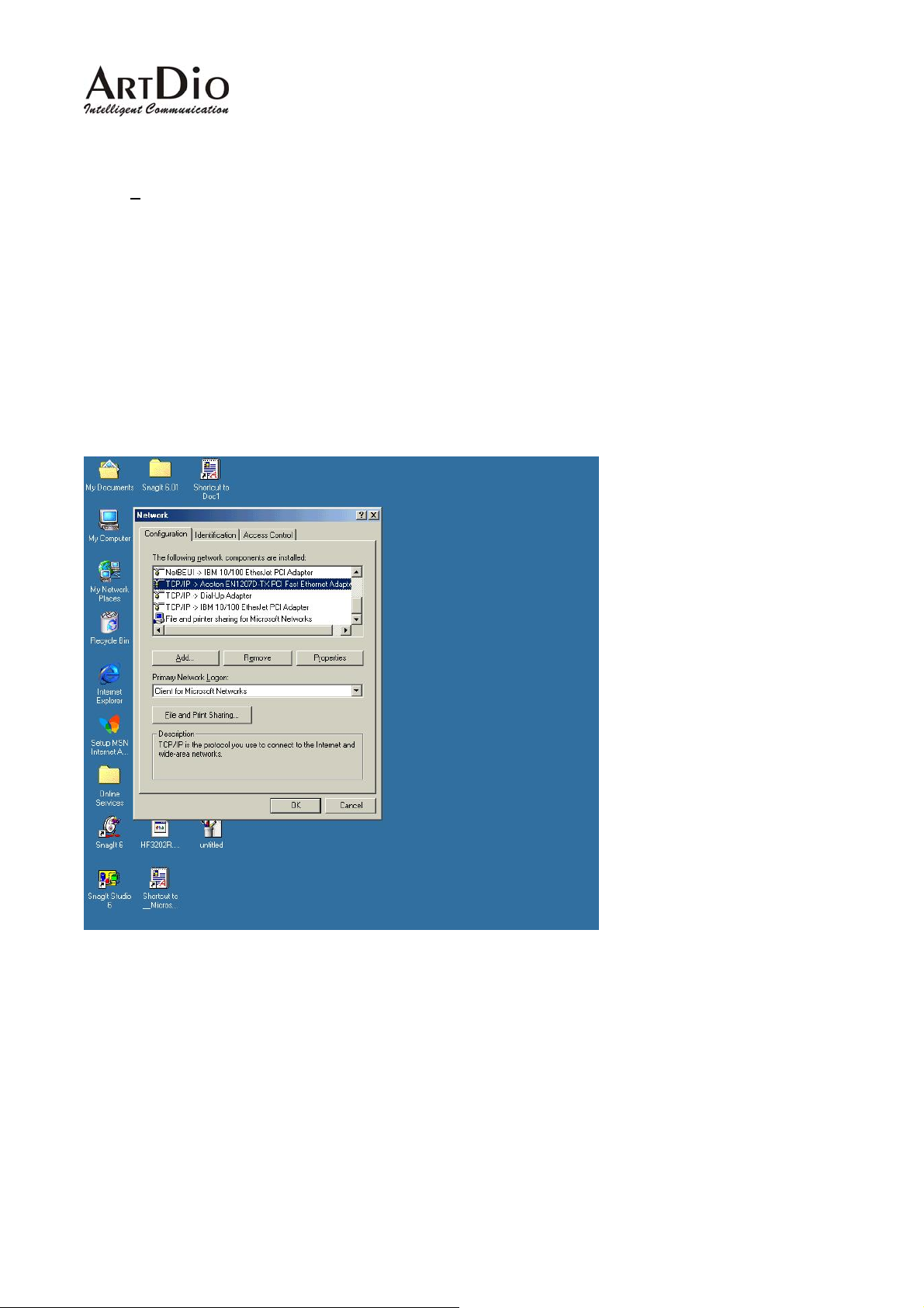
Use the provided Ethernet cable to connect your PC to the port labeled “PC”, located on the rear panel
of the IPS unit.
Because the IPS-1000 series unit’s default IP setting is 192.168.0.2, you must configure your PC to the
same subnet. “192.168.0.x” for example. The following example uses 192.168.0.5 for the IP address
and 255.255.255.0 for the subnet mask.
19
Page 20
IPS 1000 Series VoIP Gateway
After you have completed the PC’s IP address setting, you will be required to restart the PC in order for
the new settings to take effect.
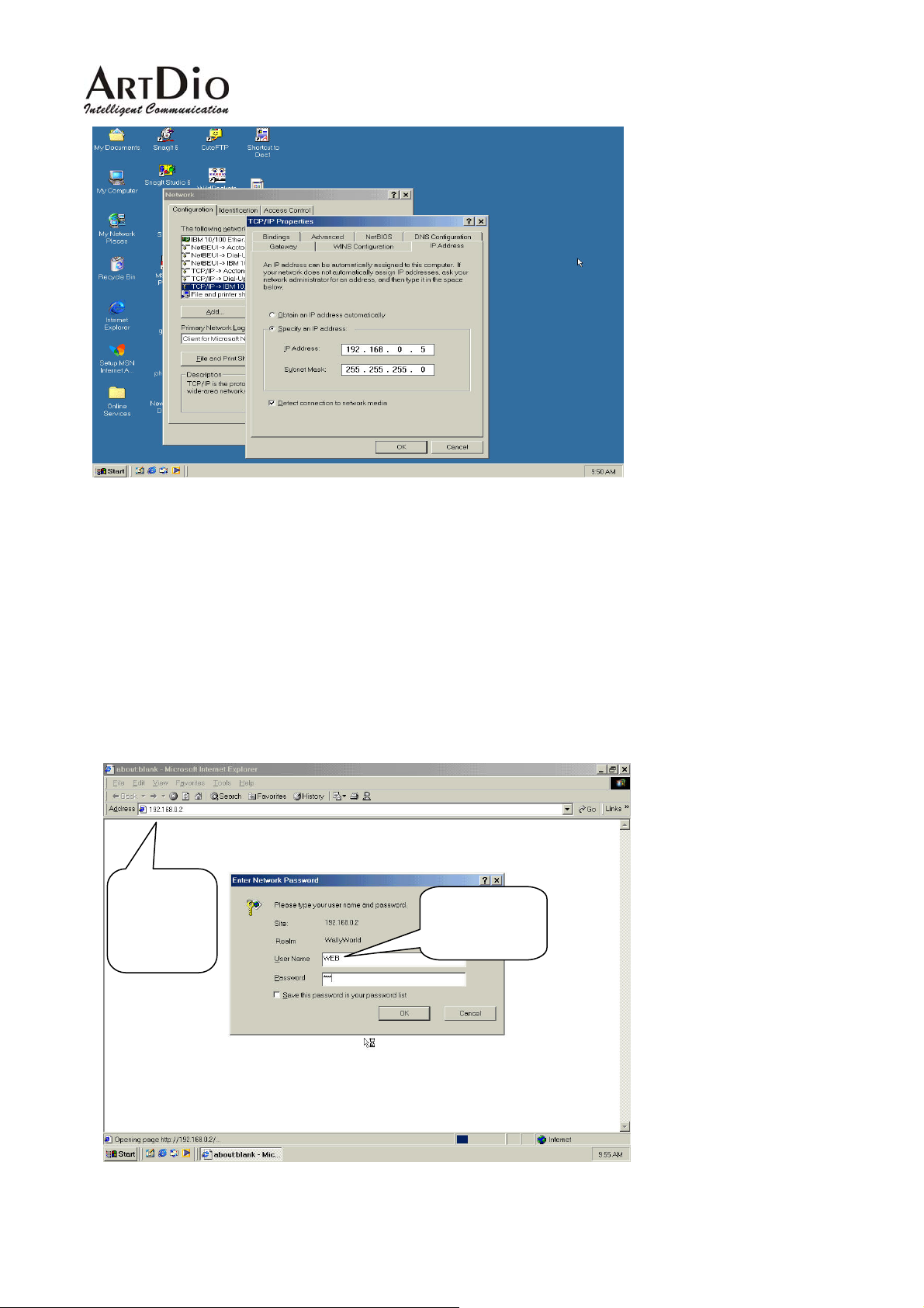
Step 3: Using the browser to configure the PPPoE Parameters of the gateway.
On the PC that is connected to the IPS unit, enter the IPS unit’s IP address (Default 192.168.0.2) and
press enter. The IPS will then prompt you with a dialogue box requesting that you enter a password. Use
“WEB” (all capitals), for the User field and “123” for the password field that you have previously
configured. Click the OK button; you should now have access to the IPS unit’s web based management
interface page.
The
MOSA
unit’s IP
“WEB”
should be all
20
Page 21
IPS 1000 Series VoIP Gateway
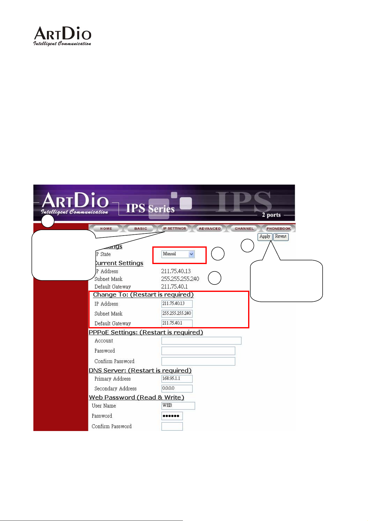
Upon entering the web based configuration interface.
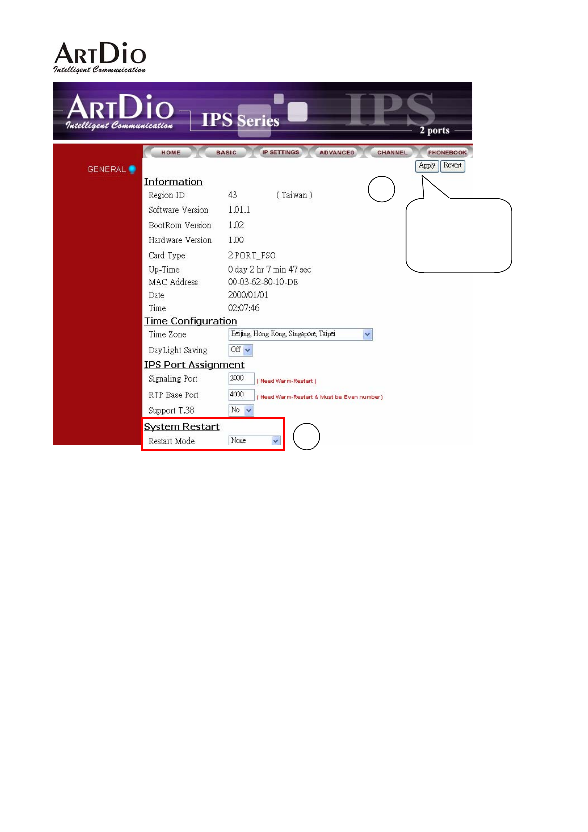
Click on “IP SETTING” at the top of the page and you will see the page as shown in the following image.
Select PPPoE from the “IP State” pull down menu.
Fill in the “Account”, “Password”, and “Confirm Password” under the PPPoE Settings. You can obtain
this information from your ISP.
Click on the Apply button.
Click the “BASIC” button at the top to go to the BASIC page and select “Warm Start” to restart the
gateway. You can also perform a warm start using the phone by picking up the handset and dialing
“##0000” then “981#”.
After restarting, the gateway will use PPPoE to obtain it’s IP address.
1
Click “IP setting”
to open this
display
3
4
2
Click the “Apply”
button to apply any
changes.
21
Page 22
IPS 1000 Series VoIP Gateway
Click the “Apply”
button to apply
any changes.
5
At this stage, your IPS should be able to use PPPoE to access the Internet. However, if you configured a
wrong account number or password, your IPS cannot access the Internet. You are not able to use PC to
access IPS by using the IP address of 192.168.0.2 because IPS has been set in PPPoE mode. You
have to use phone set to configure IPS back to fix IP mode (##0000 010#) and use PC browser to
configure correct parameters.
22
Page 23
IPS 1000 Series VoIP Gateway
10. SIP Configuration
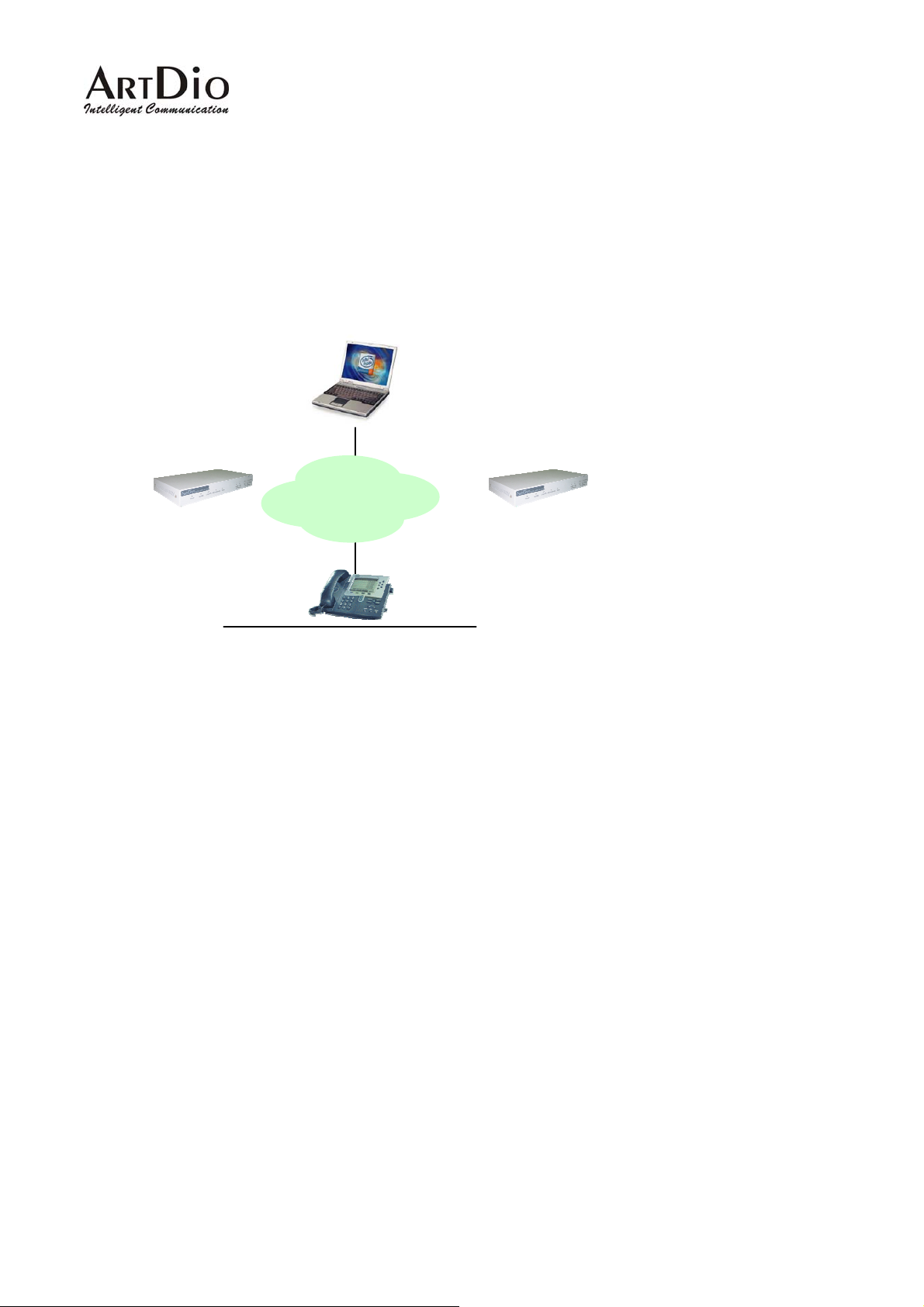
IPS 1000 not only can make regular PSTN calls, it also can communicate with IP Phones or Soft-Phones
by using SIP protocol. Previous paragraphs have described the way to make regular IP calls. This
section shows you what parameters you need to configure for SIP calls and how to make the SIP calls.
SoftPhone ( Notebook /PC )
Notice: These configurations on WEB page, after select or input value in the field, please press “Apply”
button to save and confirm the setting. Some parameters need “Warm-restart”, please process the
restart action, thanks.
IPS 1000
IPS 1000 (SIP)
IP
Cisco IP Phone
23
Page 24
IPS 1000 Series VoIP Gateway
10.1. Channels and SIP entity
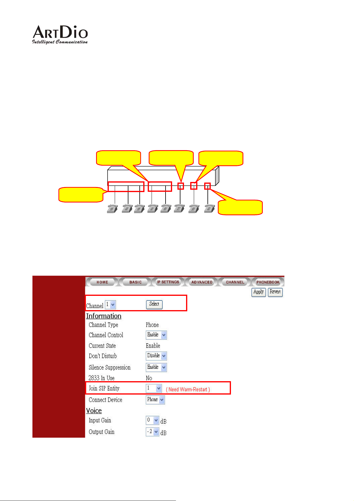
Select the channel and join a SIP entity.
Figure:
-
Configuration:
WEB page: CHANNEL\
SIP Entity 1
SIP Entity 2
IPS-1008
SIP Entity 3
SIP Entity 4
FXS
SIP Entity 5
Notice: Each channel must belong to a SIP entity.
24
Page 25
IPS 1000 Series VoIP Gateway
10.2. SIP Proxy and Register Parameters
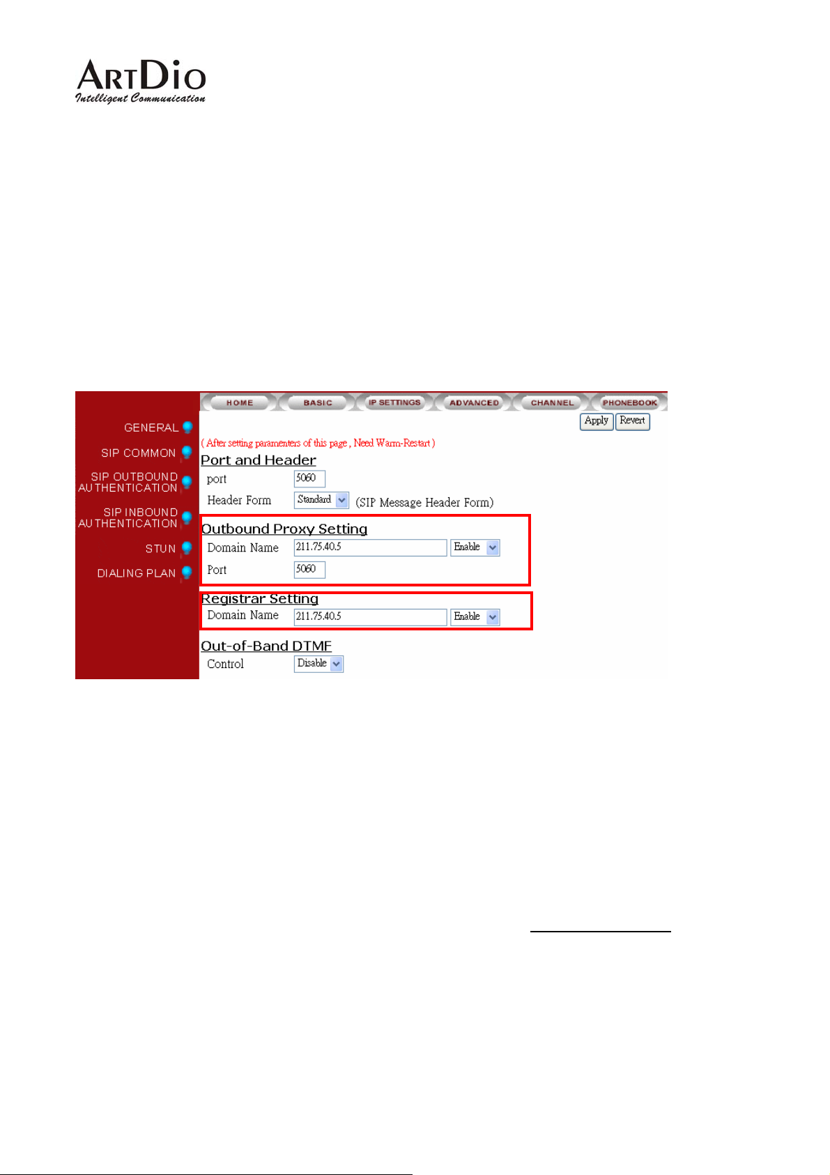
You need to configure IP address or Domain name of Registrar and Outbound Proxy server, please
check the information is right.
SIP service provider will give you an IP address or Domain name of Registrar and Outbound proxy when
you apply for the service.
Configuration
WEB Page: ADVANCED\SIP COMMOM
Notice: The Registrar Server is only for SIP entity registering. If the SIP entity register is fail, please
check the item. SIP calls are all through Outbound Proxy Server, if the parameter is not configured, the
SIP call will fail. So the two parameters must be configured.
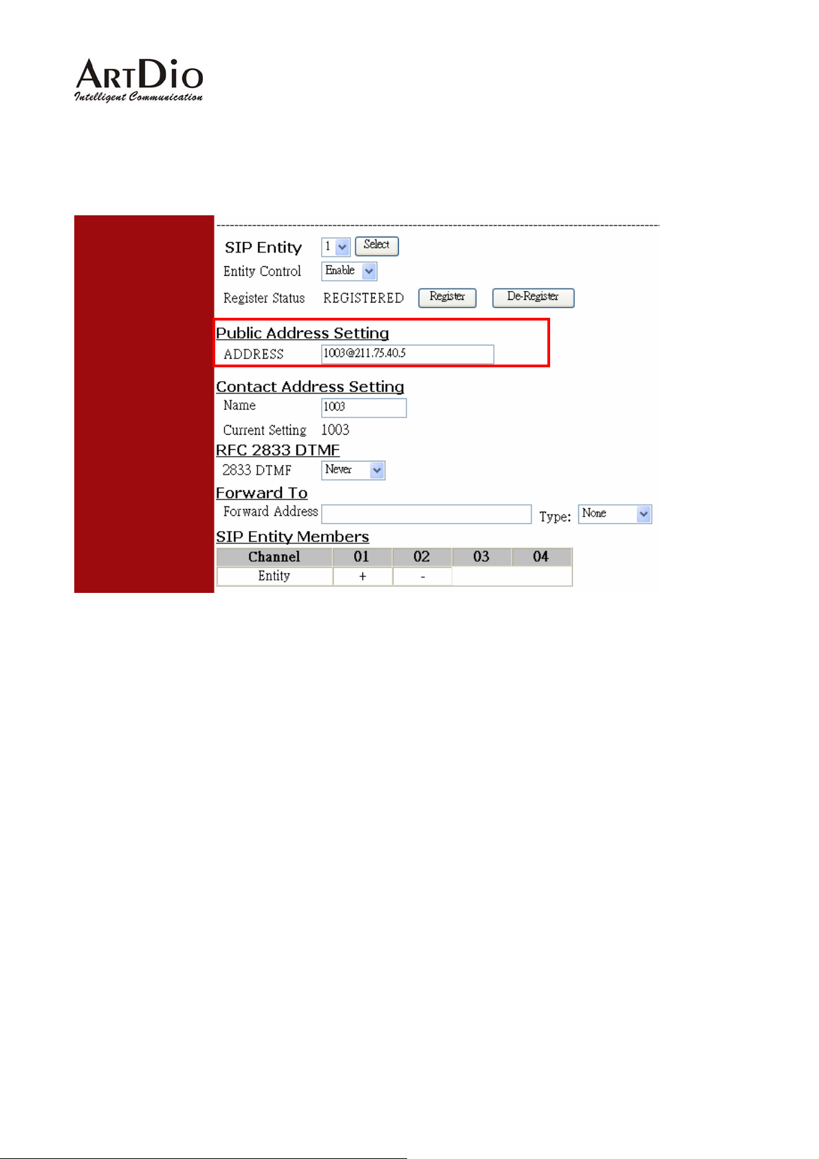
10.3. SIP Entity
SIP service provider will assign one or more SIP accounts for you when you apply for the service. In
standard, the SIP account is called ‘Public Address’, so you need to configure the account information in
‘Public Address’ item. The format is like an E-mail address such as [email protected]
.
25
Page 26
IPS 1000 Series VoIP Gateway
Configuration
WEB Page: ADVANCED \ SIP COMMON
You can control the SIP entity on WEB page, just select ‘Enable’ or ‘Disable’.
10.4. SIP Outbound Authentication
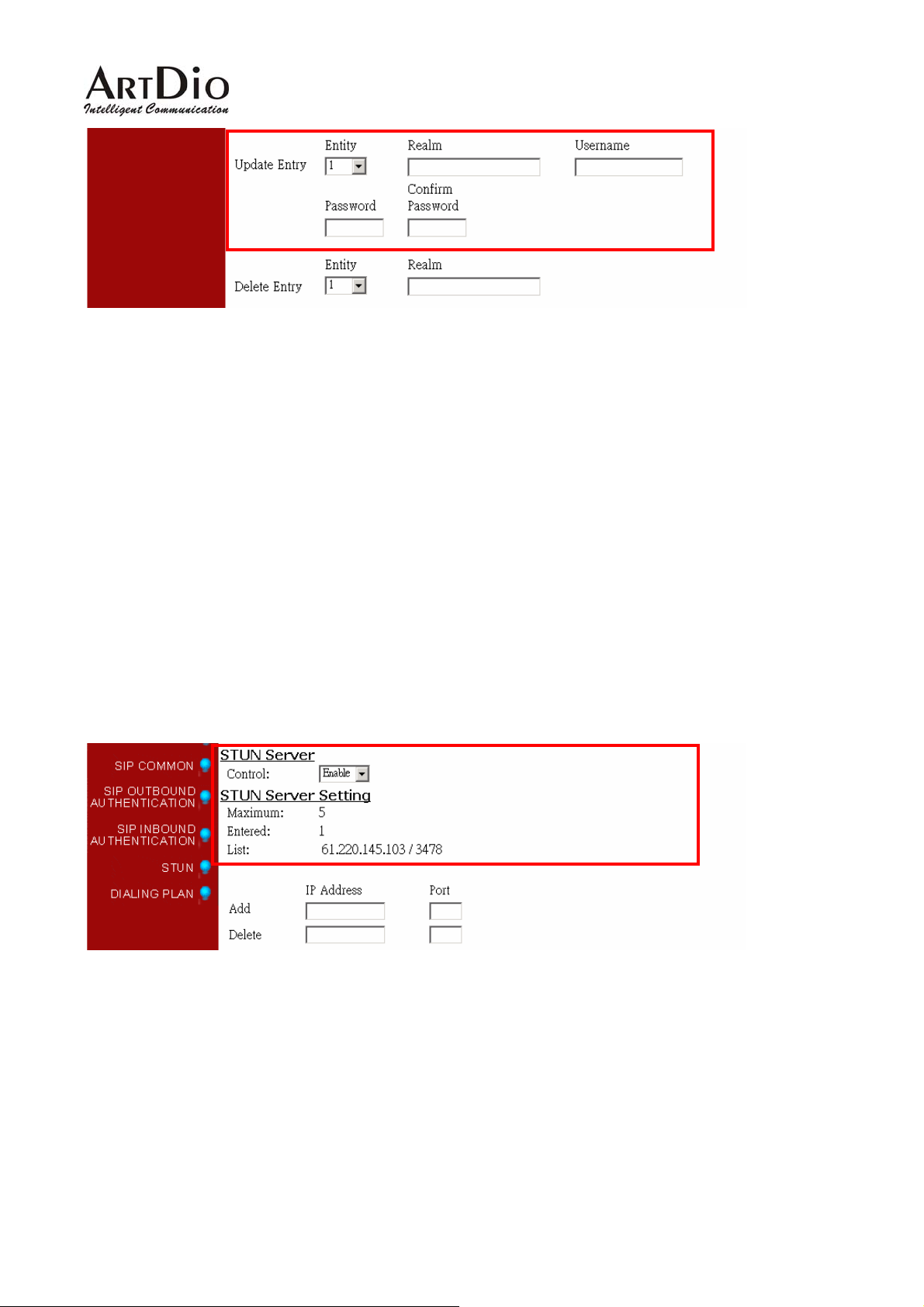
You need to configure outbound authentication for each SIP entity if SIP proxy server or other SIP phone
request for authentication. Please check with SIP service provider if you need the setting.
Please select the entity then input information includes realm, username, and password.
Configuration
WEB Page: ADVANCED \ SIP OUTBOUND AUTHENTICATION
26
Page 27
IPS 1000 Series VoIP Gateway
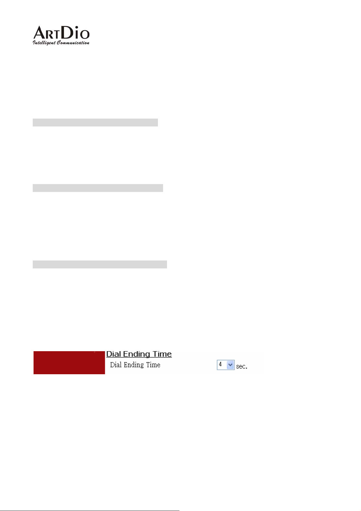
10.5. Configure STUN
The STUN (Simple Traversal UDP through NAT) server is an implementation of the STUN protocol that
enables STUN functionality in SIP-based systems. The STUN server also includes a client API t o enable
STUN functionality in SIP endpoints.
STUN is an application-layer protocol that can determine the public IP and nature of a NAT device that
sits between the STUN client and STUN server.
Notice: If your gateway is behind NAT (Use Private IP), must configure the parameter.
After configuring the parameters of STUN, please act Warm-Restart.
Configuration
WEB Page: ADVANCED\STUN
You can enable and disable the service on WEB page.
The STUN refresh time defines how long the device will send a binding request packet with discard flag
on to STUN server. A binding packet with discard flag off will be sent each time when the number of
binding request packet with discard flag on reach the Rebinding counts. The binding request packet is
used to let the STUN server keep the most fresh client information.
27
Page 28

IPS 1000 Series VoIP Gateway
10.6. Check SIP entity Status
You can use the WEB page to check the SIP entity is registered successful or unsuccessful.
WEB Page: ADVANCED\SIP COMMOM
If the status shows “REGISTERED” means successful, otherwise means fail; please notice that.
When you find the registration is fail, first check the “Registrar Setting” configuration is normal, or not
“Enable”.
Then check the “Public Address” and “Outbound Authentication” configuration is in normal status.
If the configurations are all right, please check the situation with your SIP service provider.
10.7. Phone Book
Since the SIP phone number is not easy for regular phone to dial, IPS 1000 provide a SIP phone book to
let standard phone to make a SIP call easier. The phone book uses index number to map SIP account.
For instance if the phone book is configure as below:
Notice: If your SIP account is number type like [email protected]
need to configure the items.
Configuration
WEB page: PHONEBOOK \
or [email protected], you don’t
28
Page 29
IPS 1000 Series VoIP Gateway
10.8. Make SIP Calls
After you have configured the SIP phone on the SIP phone book, you can easily make SIP calls.
You can select one way to make SIP call following these ways:
Standard Call: Only dial <numbers>+<#>.
1. Compare dialing plan, check the number if it is in setting. Example 050.
2. If the number is in setting, send the call to proxy. If communicate with proxy is fail, then the call will
be sent to PSTN.
3. If the number is not in dialing plan, the call will be sent to PSTN.
Force SIP Call: Dial <#>+ <numbers>+<#>.
1. Compare SIP Phone books; check the number if it is in phone book.
2. If the number is in setting and Proxy selection is set to "No", you will hear a busy tone. If Proxy
selection is set to "Yes", then send the call to proxy.
3. If communicate with proxy is fail, you will hear a busy tone.
4. If the number is not in phone book, you will hear busy tone.
Force PSTN Call: Dial <*>+<numbers>+<#>.
Always go through PSTN
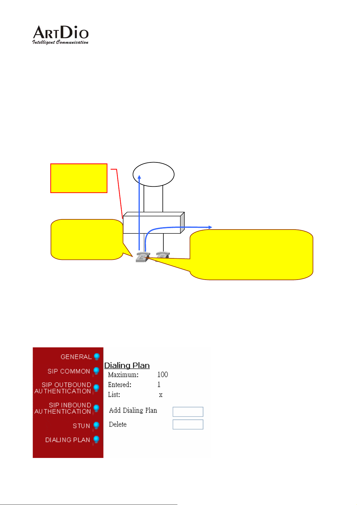
Notice: If you do not want to dial “#” after numbers, please configure the ‘Dial Ending Time’ item. After
the seconds, the call will be sent automatically.
WEB Page: ADVANCED\GENERAL
29
Page 30

IPS 1000 Series VoIP Gateway
10.9. Contact Address
The main purpose of Contact Address is making SIP calls without proxy.
The Contact Address can be any numbers or characters such as ‘Mary’ or ‘1003’.
WEB Page: ADVANCED\SIP COMMOM
Making SIP calls without proxy server:
The SIP protocol allows you to make SIP calls directly to the destination number without through the
proxy server. You can simply dial the SIP number and domain name or IP address. The typical example
is: [email protected]
Notice: For this type of SIP calls, the destination device’s IP address is already known and fixed.
30
Page 31
IPS 1000 Series VoIP Gateway
11. Other SIP Parameters
11.1. Dialing Plan
X means all calls will be send to SIP proxy first, if the SIP call is fail, and then sent to PSTN.
If the configuration is only ‘050’ means the numbers like 050xxxxx will send to SIP proxy, if you dial any
other numbers like 100, the number will send to PSTN immediately.
Dialing Plan:
050 and 070
C
Configuration
WEB Page: ADVANCED\Dialing Plan
Dial 82261234
The call is sent to
PSTN immediately
IPS 1000
FXO
FXS
Dial 050123456 or 070345678
The call will be defined to SIP account
and sent to SIP Proxy. If the SIP call is
fail, then send to PSTN.
31
Page 32
IPS 1000 Series VoIP Gateway
11.2. Call Forward
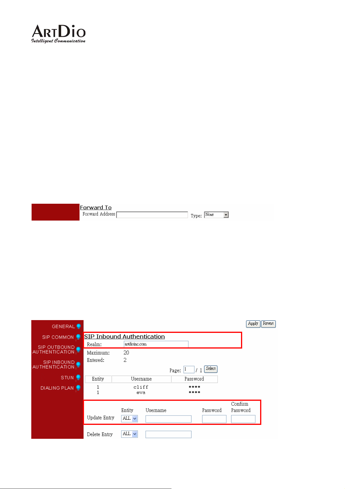
There are three forward types:
1. All: All incoming call to the SIP entity will be forward.
2. Busy: When the SIP entity is busy, the incoming call will be forward.
3. No Answer: When the SIP entity is no answer and after 30 seconds, the incoming call will be
forward.
Notice: In order to let the caller identify the port has been configured ”forward”; the caller will hear
second dial tone, rather than normal dial tone.
Configuration
WEB page: ADVANCED\SIP COMMOM
Phone Set: Please refer to section Appendix A: Phone-Set Command.
11.3. Inbound Authentication
You need to configure inbound authentication if you request authentication for other SIP phone to call
you.
Configuration
WEB Page: ADVANCED \ SIP INBOUND AUTHENTICATION
32
Page 33
IPS 1000 Series VoIP Gateway
11.4. FAX
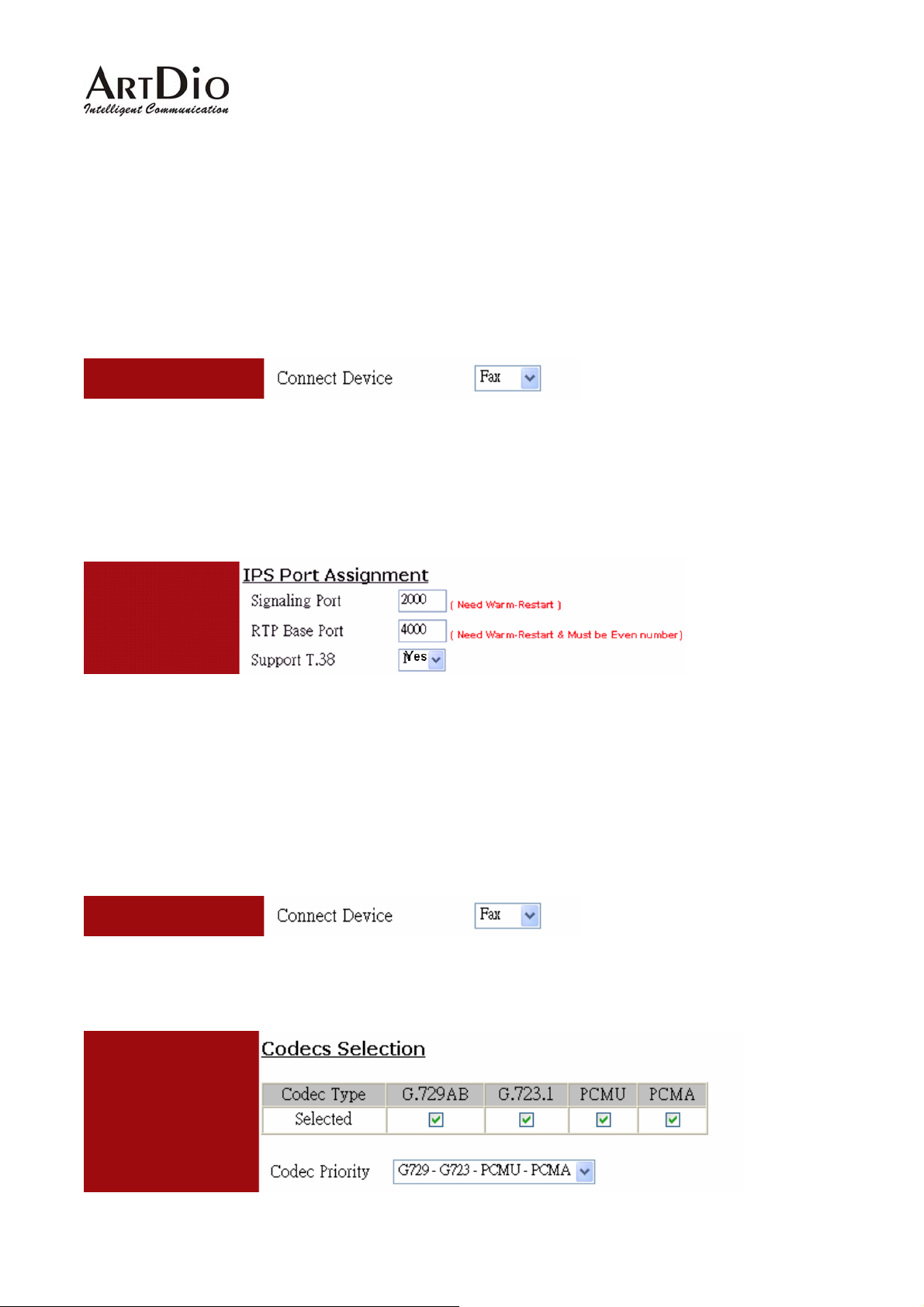
11.4.1. The devices at two sides are all IPS 1000 series gateway
Use the FAX protocol that is the proprietary protocol of IPS (supporting T.38). Setup method is listed
below:
1. Web Folder: “Connect Device” in “Channel” folder. Select “FAX” and then click “Apply” button
2. Web folder: “IPS Protocol” in “Basic” folder
Signaling Port: input “2000”
Support T.38: select “Yes”
Click “Apply” button
3. Warm-Restart the system
11.4.2. The devices at two sides are IPS 1000 and the other brands
Use the FAX protocol as G.711 (non-supporting T.38). Setup method is listed below:
1. Web folder: “Connect Device” in “Channel” folder. Select “FAX” and then click “Apply” button
2. Setup “Check Protocol”, web folder: ADVANCED\SIP COMMON
Select and mark “PCMU” and “PCMA” Codecs, than click “Apply” button
33
Page 34

IPS 1000 Series VoIP Gateway
3. Web folder: “IPS Protocol” in “Basic” folder
Signaling Port: input “0”
Support T.38: select “No”
Click “Apply” button
4. Warm-Restart the system
12. WEB MANAGEMENT INTERFACE
The Tree Architecture of Web Management
HOME BASIC GENERAL
IP SETTING
ADVANCED
CHANNEL
PHONE BOOK
ACCESS
CODE
General
SIP COMMON
SIP OUTBOUND
AUTHENTICATION
SIP INBOUND ATHENTICATION
STUN
Dialing Plan
34
Page 35
IPS 1000 Series VoIP Gateway
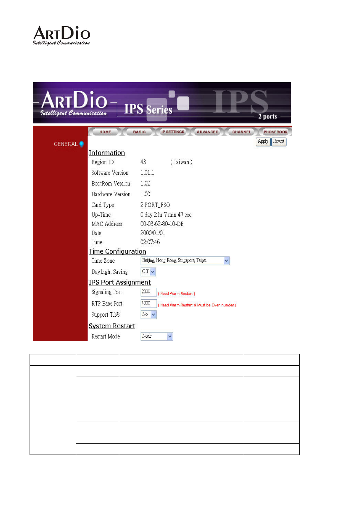
12.1. BASIC / GENERAL
Category Section Description Default Setting
Information
Region ID Display region ID.(Read only) 0
Software
Version
BootRom
Version
Hardware
Version
Card Type Display card type. (Read only)
Display software version.(Read only)
Display BootRom Version.(Read only)
Display hardware Version.(Read only)
35
Page 36

IPS 1000 Series VoIP Gateway
Up-Time Display the use time since from system
reboot.(Read only)
Time
Configuration
IPS
protocol
MAC
Display MAC address.(Read only)
Address
Date Show the date
Time Show the time
Date Manually Input date, only effected in
Manual Mode.
yyyy / mm / dd
Time Manual input time, only effected in
Manual Mode of Time Source.
hh : mm : ss
Time Zone Select local system time zone. Select
correct Time Zone.
Daylight
saving
Signaling
Port
ON: Enable daylight saving.
OFF: Disable daylight saving.
UDP port to transfer signal packets. It
can be setting in the range of 0 to
Empty
Empty
OFF
0
System
Restart
RTP
Base Port
Support
T.38
Restart
Mode
65535. (Must reboot system to apply
changes)(Only support IPS device)
Base of UDP port to receive RTP
packets. It can be setting in the range of
0 to 65534.( Must be Even, after setting
this item, please reboot system to apply
changes)
Enable/Disable the FAX relay (T.38) of
IPS Protocol
None: Not to restart system.
Cold restart: Cold restart.
Warm restart: Warm restart.
4000
No
None
36
Page 37
IPS 1000 Series VoIP Gateway
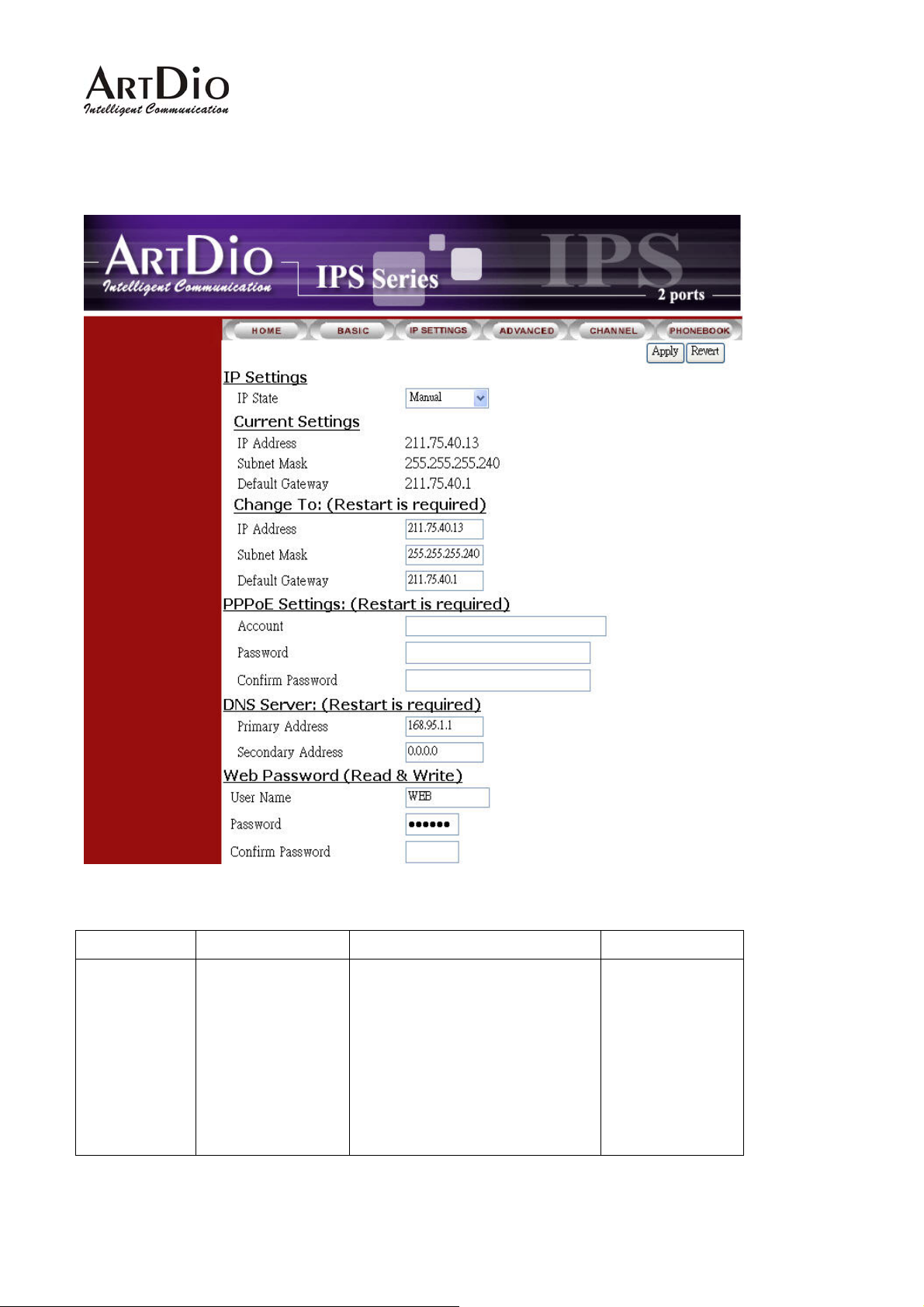
12.2. IP SETTING
Category Section Description Default Setting
IP Settings IP State The way to obtain IP address:
Manual: Entered by user
(Static IP)
Auto(DHCP): Assigned by
DHCP server
PPPoE: Assigned by PPPoE of
ISP
37
Manual
Page 38

IPS 1000 Series VoIP Gateway
Current Setting Display the configured IP
192.168.0.2
PPPoE
Settings
address, subnet mask address
and default gateway. (Read
only)
Change To Enter the IP address that will
be used after next restart,
Including:
IP Address
Subnet Mask Address
Default Gateway
(This item is used only on
Manual mode of IP Setting.)
Account The user’s account of PPPoE
protocol, provided by ISP.
Password The user’s password of PPPoE
protocol.
Confirm
Password
Confirm the user’s password of
PPPoE protocol.
255.255.255.0
192.168.0.1
DNS Server
Web
Password
Service Name The service name of PPPoE
account, provided by ISP.
(Most ISP doesn’t need this)
Primary Address The primary address of DNS
server. The default setting
would be different according to
the local area. In Taiwan, the
default setting is 168.95.1.1.
Secondary
Address
The secondary address of
DNS server.
User Name The user’s name of Web
Management Interface.(12
character)
Password The password of Web
Management Interface.( 6
character)
168.95.1.1
WEB
Password
Confirm
Enter the password again to
confirm it.
38
Page 39
IPS 1000 Series VoIP Gateway
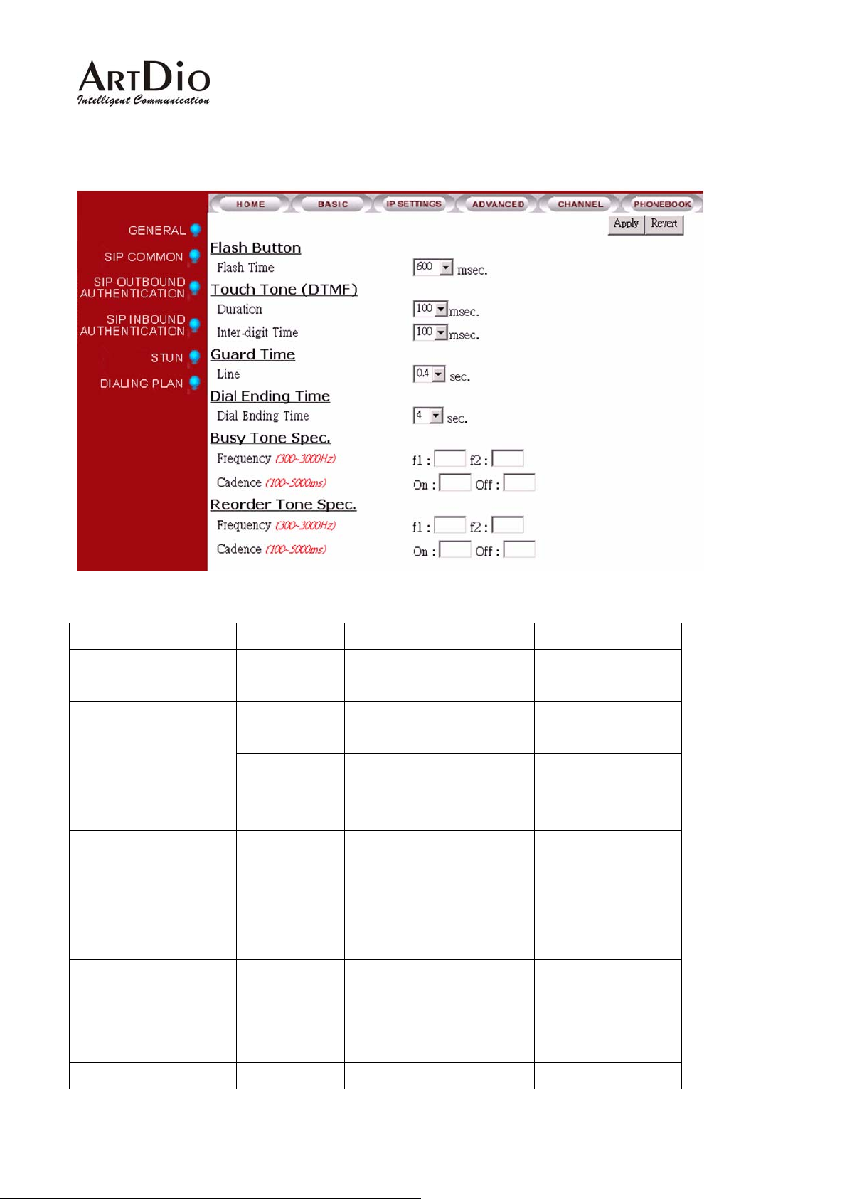
12.3. ADVANCED / GENERAL
Category Section Description Default Setting
Flash Button Flash Time System confirmed
“Flash” time.
Duration The duration to send a
DTMF.
Inter-digit The inter-digit time of
sending string of DTMF
digits.
Guard Time Line The time defines how
long the system will not
take incoming call after
call has been
disconnected.
Dial Ending Time Dial Ending
The time specifies how
200 msec
100 msec Touch Tone (DTMF)
100 msec
0.8 sec
4
Time
Busy Tone Spec Frequency f1, f2
long to end the dialing
number if a ‘#’ digit is
missing.
1-10 (seconds)
(300 ~ 3000Hz)
39
Page 40

IPS 1000 Series VoIP Gateway
Cadence on, off. The on and off
(100 ~ 5000ms)
duration in playing the
tone
Reorder Tone Spec
Frequency f1, f2
Cadence on, off. The on and off
duration in playing the
tone
(300 ~ 3000Hz)
(100 ~ 5000ms)
40
Page 41
IPS 1000 Series VoIP Gateway
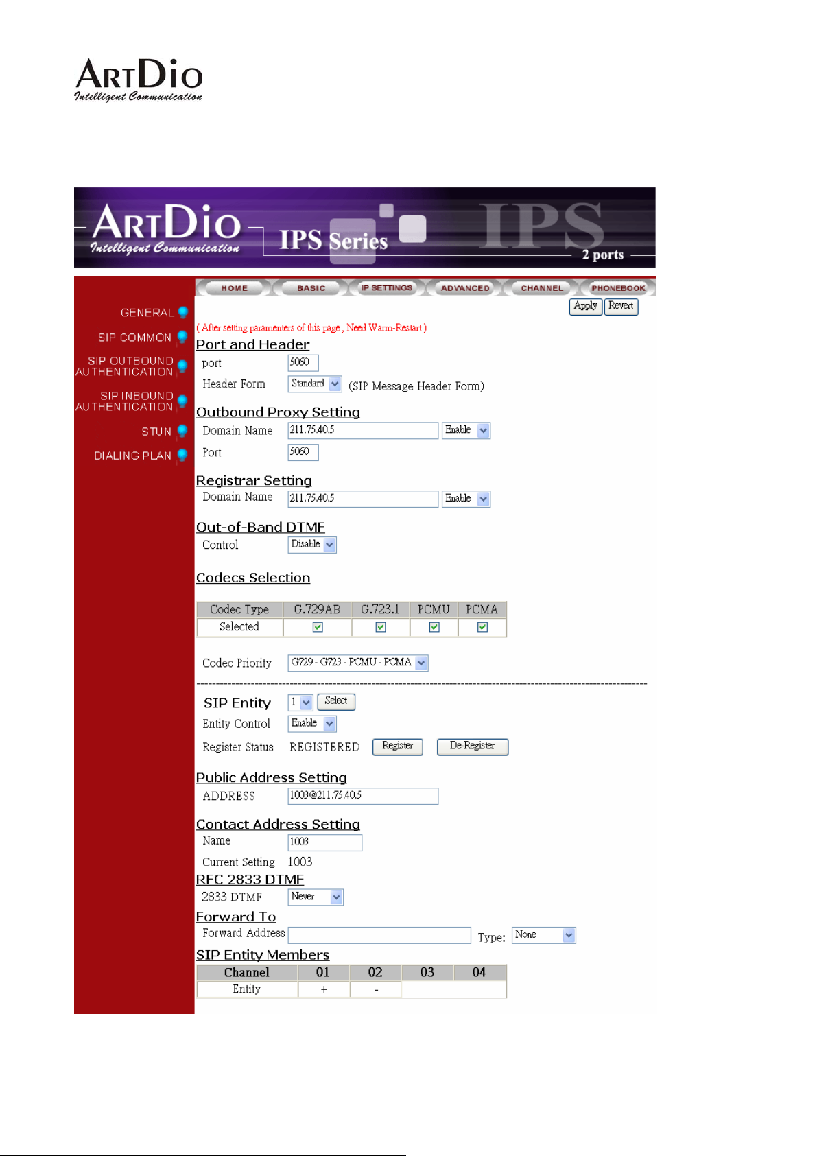
12.4. SIP COMMON
41
Page 42

IPS 1000 Series VoIP Gateway
Section Item Field Description Default
Port The control port number of SIP protocol. 5060 Port and Header
Header
Form
Select ‘Standard’ or ‘Compact’ to be the
header format of SIP packet. When
Standard
Compact is selected, the header will be
shorter and it saves bandwidth.
Outbound Proxy
Setting
Domain
Name
Domain name or IP address of proxy. Empty
Disable
Port Control port number of SIP protocol. 5060
Registrar Setting Domain
Name
Domain name or IP address of proxy
that you want to register.
Empty
Disable
Out-band DTMF Control Enable/Disable Disable
Codecs Selection Codec
Type
G.729AB: Mark the selection to Enable
G.729AB Codec
G.723.1: Mark the selection to Enable
Enable
Enable
G.723.1 Codec
PCMU: Mark the selection to Enable
Enable
PCMU Codec
PCMA: Mark the selection to Enable
Enable
PCMA Codec
Codec
Priority
SIP Entity Select an entity
You can select the codec priority for
your requirement.
G729-G723-P
CMU-PCMA
1
Select: Select Button
Register: Register Button
De-Register: Cancel Register Button
Entity Control Select Enable/Disable Enable
Register Status Register
Status
Show the register status, if it shows
Registered means successful. (Read
Empty
only)
Register: Register Button
De-Register: Cancel Register Button
Public Address
Address Enter SIP phone number of the port.
Empty
Setting
The phone number general assigned by
SIP service provider.
42
Page 43

IPS 1000 Series VoIP Gateway
Section Item Field Description Default
Contact Address
Setting
Forward To
Name Enter Contact Address. You can assign
a name for the port. However, it should
be unique within per channels.
Current
Setting
2833
Display current setting of
Contact Address
Enable/Disable RFC 2833 DTMF. Never RFC 2833 DTMF
(Read Only) 01
DTMF
2833 In
Use
Forward
Address
Display current status of
(Read Only)
DTMF configuration.
Enter a SIP account (Public Address)
forward. When users dial into the SIP
Entity, the call will be forwarded to the
number.
Type N/A: All incoming calls are forward.
Busy: When the SIP entity is busy, the
calls will be forward.
Empty
Empty
N/A
SIP Entity
Members
No Answer: When the SIP entity is no
answer about 30 seconds, the calls will
be forwarded.
Channel Show the all channels Depend on
gateways
Entity Show ‘+ ‘means the SIP entity is for the
Empty
channel.
43
Page 44
IPS 1000 Series VoIP Gateway
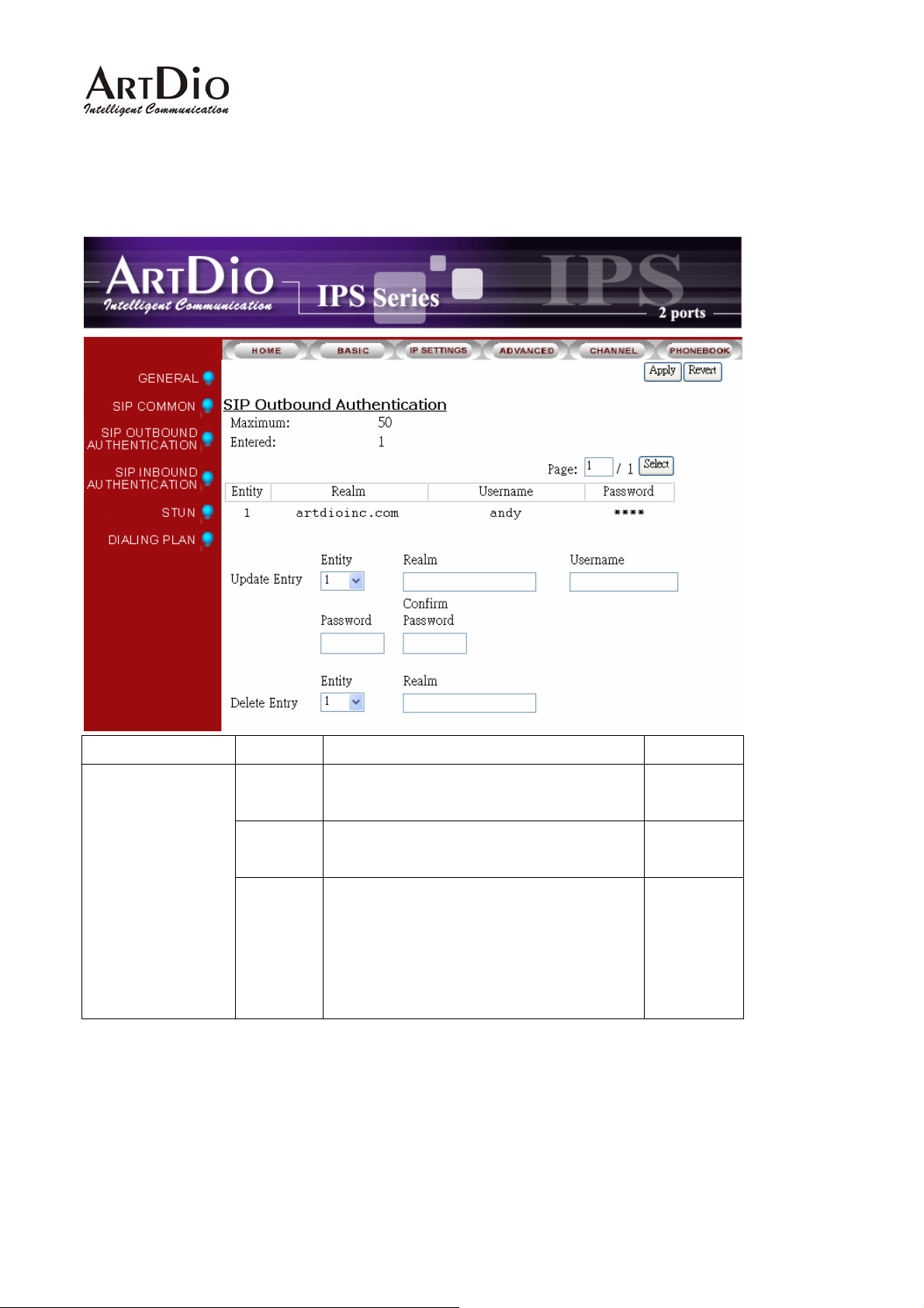
12.5. SIP OUTBOUND AUTHENTICATION
Section Item Field Description Default
SIP Outbound
Authentication
Maximum Maximum number of entries
allowed
Entered Number of entries of
authentication entered.
Entries
List
List of entries (Read Only)
Entity: Which entity that you select.
Realm: Domain name or IP address.
Username: Username of authentication.
Password: Password of authentication.
(Read Only) 50
(Read Only) 0
Empty
44
Page 45
IPS 1000 Series VoIP Gateway
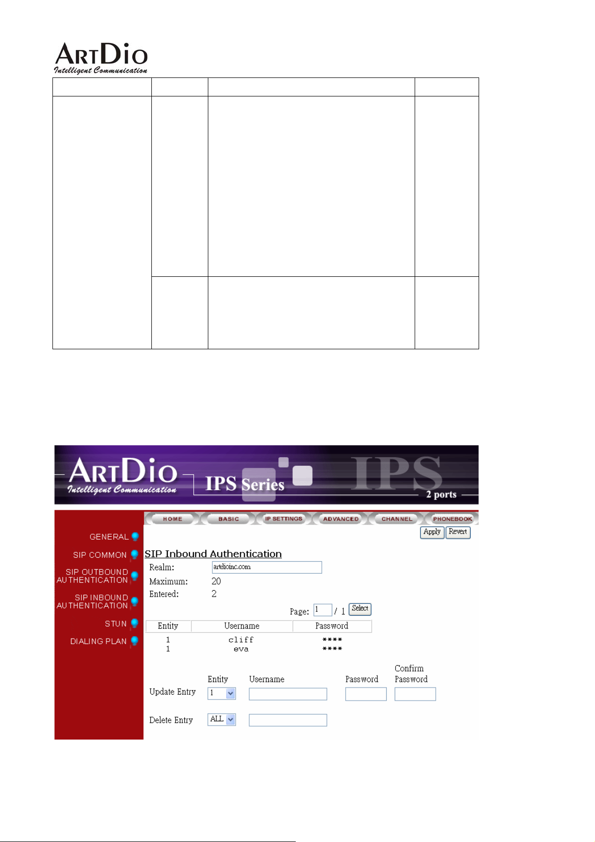
Section Item Field Description Default
Update
Entry
Delete
Entry
Enter the information of outbound
authentication
Entity: Select an entity.
Realm: Domain name or IP address.
Username: Enter Username of
authentication.
Password: Enter password of
authentication.
Confirm Password: Enter password again
for confirmation.
Delete the information of outbound
authentication
Entity: Select an entity.
Realm: Domain name or IP address.
Empty
Empty
12.6. SIP INBOUND ANTHENTICATION
45
Page 46
IPS 1000 Series VoIP Gateway
Section Item Field Description Default
SIP Inbound
Authentication
Realm Enter domain name or IP address Empty
Maximum Maximum number of
entries allowed
Entered Number of entries of
authentication entered.
Display the entries (Read Only)Entries List
Entity: Which entity that you select.
Username: Username of authentication.
Password: Password of authentication.
Update Entry Enter entries of authentication
Entity: Which entity that you select.
Username: Username of authentication.
Password: Password of authentication.
Confirm Password: Enter password
again for confirmation.
Delete Entry Delete entries of authentication
(Read Only) 20
(Read Only) 0
Empty
Empty
Empty
Entity: Which entity that you want to
delete.
Username: Username of authentication.
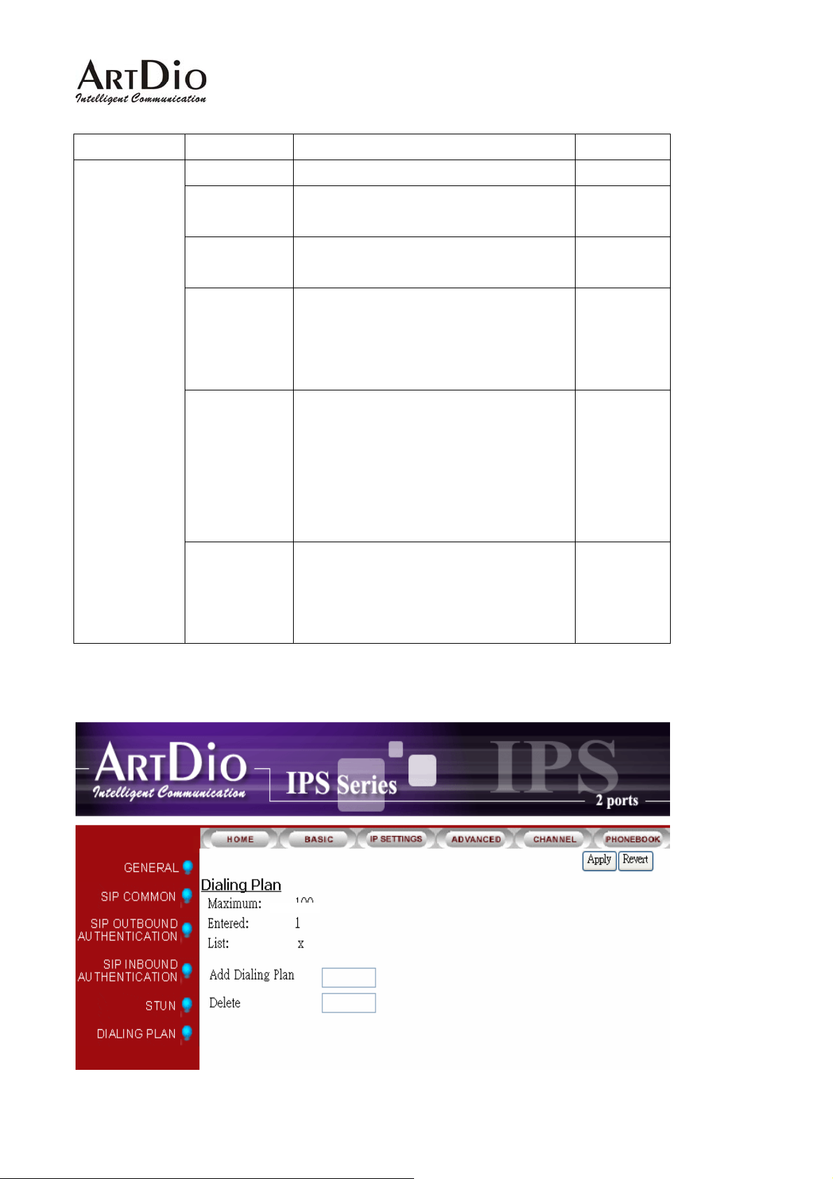
12.7. Dialing Plan
46
Page 47

IPS 1000 Series VoIP Gateway
Section Item Field Description Default
DIALING PLAN
Maximum Maximum number of
(Read Only) 100
entries allowed
Entered Number of entries of
(Read Only) 0
authentication
entered.
Display the entries (Read Only)List
x
The default value “x“means that all
numbers that you dial will first go
through SIP proxy. If the call
communicates with SIP proxy is
fail, it will be transferred to PSTN.
Add Dialing Plan Enter numbers. Example: 050. Empty
Delete Entry Enter numbers for delete. Empty
47
Page 48
IPS 1000 Series VoIP Gateway
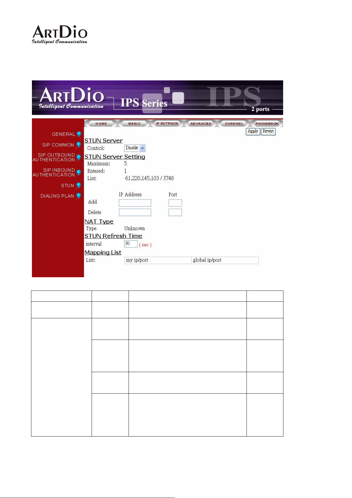
12.8. STUN
Section Item Field Description Default
STUN Server Control Enable or Disable STUN Server service. Disable
STUN Server
Setting
Maximum Maximum number of
entries allowed
Entered Number of entries of
STUN server that have
been entered.
List Display all of servers that
have been entered.
Add Add a stun server
IP Address: Enter IP address or Domain
Name
Port: Enter port number of service.
(Read Only) 5
(Read Only) 0
(Read Only)
Empty
48
Page 49
IPS 1000 Series VoIP Gateway
Section Item Field Description Default
Delete Delete a stun server
IP Address: Enter IP address or Domain
Name.
Port: Enter port number of service.
NAT Type Type Display NAT type (Read Only) Unknown
Stun Refresh Time Interval It defines how long the device will send
a binding request packet with discard
flag on to STUN server.
Mapping List List
My ip/port: shows the
private IP and port
number.
Global ip/port: Display
public IP and port number.
(Read Only) Empty
Empty
30
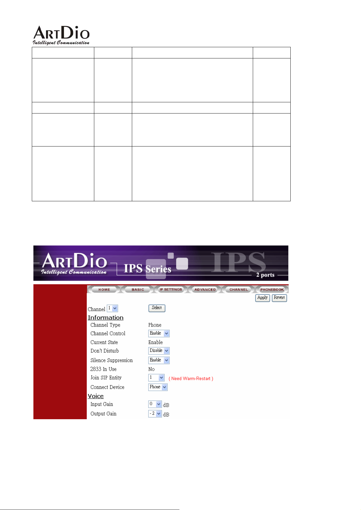
12.9. CHANNEL
49
Page 50

IPS 1000 Series VoIP Gateway
Category Section Description Default
Setting
Channel Channel number: 1
Information
Channel
Type
Display port type. (Read only)
Phone: FXS Interface, connect
to telephone set or Fax
machine.
Line: FXO Interface, connect to
phone line.
NA: Not available.
Channel
Control
Enable/Disable all functions of
this port.
Enable/Disable
Current State Display the current state of this
port. (Read only)
Enable/ Disable.
Do not
Disturb
Silence
Enable/Disable does not
disturb function
Enable/Disable the function. Disable
Enable
Disable
Suppression
2833 In use Yes:
(Read only)
No:
Join SIP
Select an Entity for SIP. 1
Entity
Connect
Device
Phone: Connect to the FXS
port is regular phone
Phone
FAX: Connect to the FXS port
is FAX machine
Input Gain Adjust Voice input Gain 0 Voice
Output Gain Adjust Voice output Gain 0
50
Page 51
IPS 1000 Series VoIP Gateway
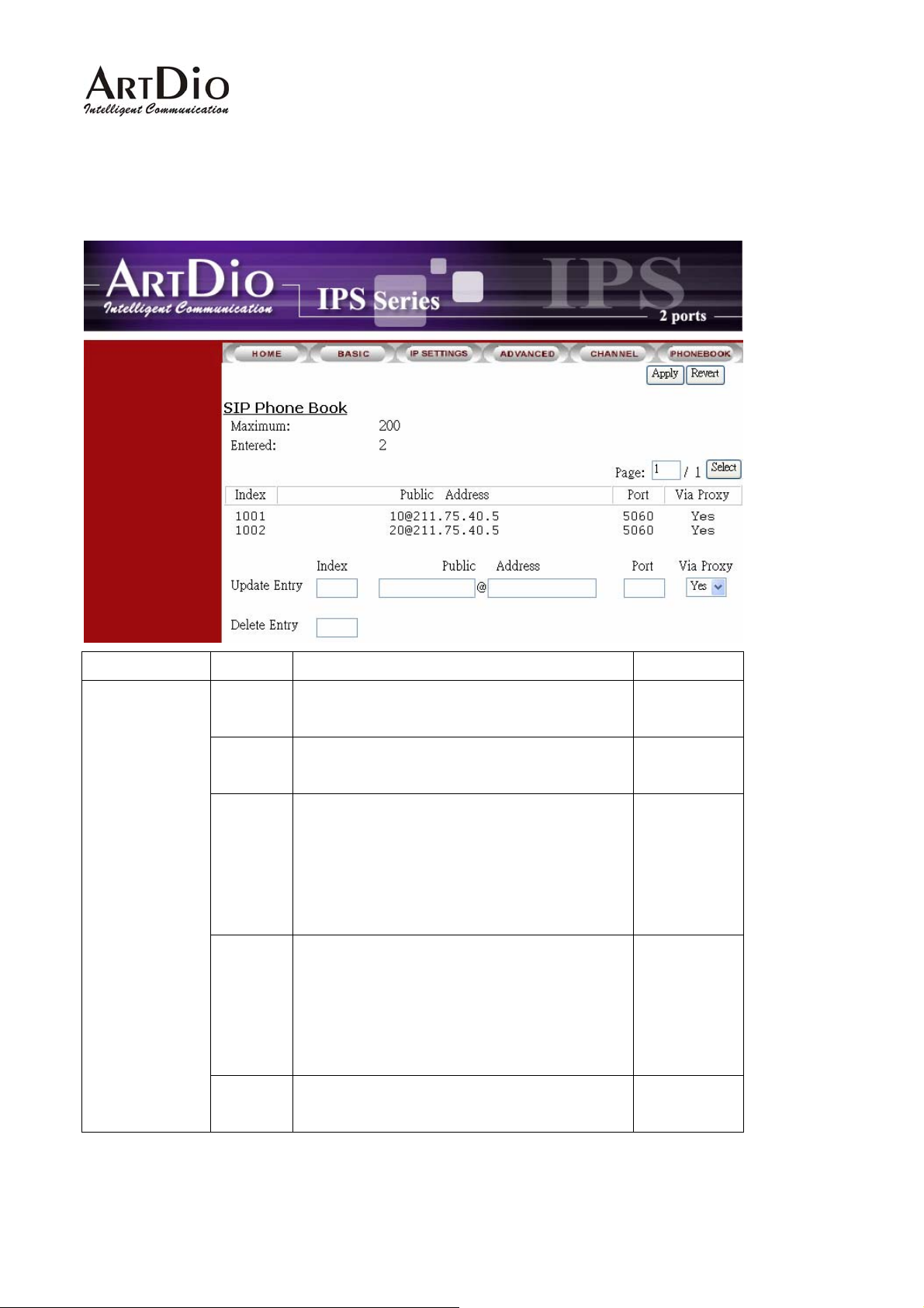
12.10. PHONE BOOK
Section Item Field Description Default
SIP Phone Book
Maximum Maximum number of entries
allowed
Entered Number of entries of phone
books entered.
Display phone books (Read Only) Entries
List
Update
Entry
Index: Dialing number
Public Address: SIP account.
Port: Port number.
Via Proxy: Via proxy or not.
Enter entries
Index: Enter dialing number
Public Address: Enter SIP account.
Port: Enter port number
Via Proxy: Select via Proxy or not
(Read Only) 200
(Read Only) 0
Empty
Empty
Delete
Entry
Delete entries
Index: Enter the index for delete.
51
Empty
Page 52
IPS 1000 Series VoIP Gateway
13. Use Private IP (Behind NAT)
Using a Private IP in a NAT Environment
The IPS unit is able to communicate with other IPS units under a NAT environment using Private IP
addresses on the LAN side of your IP Sharing device. However you must configure the IP Sharing
device to treat the IPS unit as a Virtual Server using UDP port 5060, 2000.
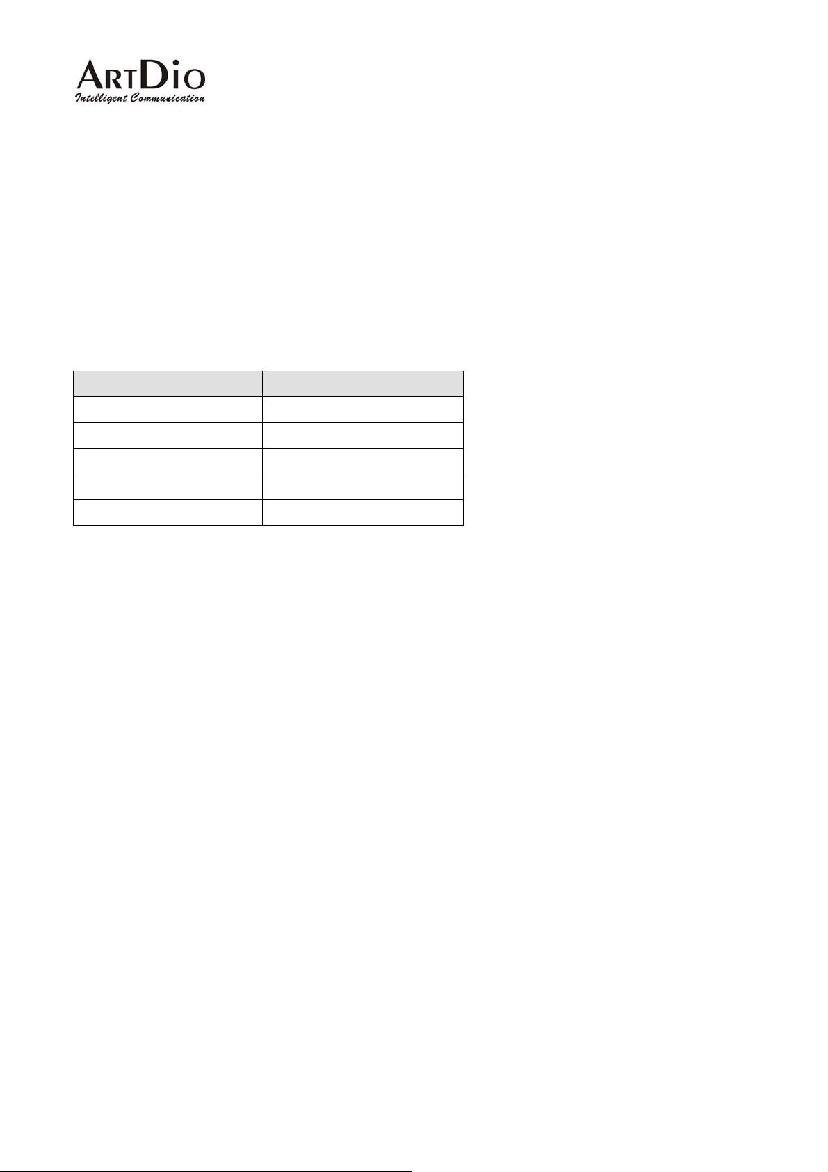
You will have to ask MIS personnel to enable the ports listed in the following table.
Packet Modes Using Ports
SIP Signal Packets UDP 5060
IPS Signaling Port UDP 2000
IPS RTP Base Port UDP 4000
FTP software upgrade TCP 21
Web management TCP 80
If you want to use private IP behind NAT and Proxy Server is in Internet, you must need to enable STUN
service. If the system is installed in VPN, it is not necessary to Enable Stun.
52
Page 53

IPS 1000 Series VoIP Gateway
14. Appendix
14.1. Appendix A: Phone-Set Command
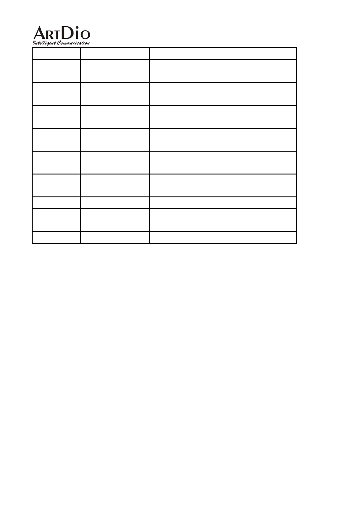
Pick up the handset and listen for the dialing tone. Dial “##0000 and listen for three consecutive tones
before setting the following parameters. After input the parameters, please dial ‘# to end the
configuration.
Command Description
01 IP State 0 : static; 1: DHCP; 2: PPPoE
02 IP Address xxx*xxx*xxx*xxx
03 Subnet Mask xxx*xxx*xxx*xxx
04 Default Gateway xxx*xxx*xxx*xxx
05 Primary DNS Server
IP
06 Second DNS Server
IP
07 Select Signaling Port 0~65535
08 Select RTP Base Port 0~65534 (limit to even port number only)
09 PPPoE username User name (use the mapping table to map
10 PPPoE password Password (use the mapping table to map
11 DND 0 : Disable ; 1: Enable
Parameters
xxx*xxx*xxx*xxx
xxx*xxx*xxx*xxx
character into digits)
character into digits)
12 SIP Forward State 0 : Disable ; 1: Enable; 2: Busy; 3: No Answer
13 SIP Forward Target 6 Digits
14 Change Service Port 1:FTP; 2:HTTP 3:Telnet (Port: 0-65535)
15 Change WEB
Password
16 Change FTP
Password
40 Listen for the IP
Address
41 Listen for the Subnet (ending ”#” is not required)
6 digits
6 digits
(ending ”#” is not required)
53
Page 54
IPS 1000 Series VoIP Gateway
Mask
42 Listen for the Default
(ending ”#” is not required)
Gateway
43 Listen for Current
(ending ”#” is not required)
Signaling Port
44 Listen for Global IP
(ending ”#” is not required)
Address
45 Listen for Global
(ending ”#” is not required)
Signaling Port
46 Listen for WEB, FTP,
1:FTP; 2:HTTP 3:Telnet
Telnet Port
47 Listen for Current
(ending ”#” is not required)
Public Address
96 Region ID 2 digits
97 Reset unit to Factory
1: reset all; 2: keep IP
Default values
98 System Warm Restart 1: do it
54
Page 55

IPS 1000 Series VoIP Gateway
14.2. Appendix B: Console Command
User Exec commands
Enable Turn on privileged commands
Exit Exit from the EXEC
Help Description of the interactive help system
Show Show running system information
show
Dns Show the IP address of domain name server
ethernet Fast Ethernet port status and configuration
history Display the session command history
Ip Display IP configuration
running-config Show current operating configuration
version System hardware and software status
Privileged Mode
Configure Enter configuration mode
Delete Reset configuration
Disable Turn off privileged commands
Exit Exit from the EXEC
Help Description of the interactive help system
Ping Send echo request to destination
Probe-hook probe busy tone cadence
Probe-remove stop probe busy tone cadence
Reload Halt and perform cold start
Restart Halt and perform warm start
Show Show running system information
Global Mode
Dbflush Data Base flush
Dns Set the IP address of domain name server
End Exit from configure mode to privileged mode
Exit Exit from configure mode
Help Description of the interactive help system
Ip Global IP configuration subcommands
Log Control log output
No Negate a command or set its defaults
pppoe PPPoE configuration subcommands
regional_id Set regional id
service_port Set service port number
55
Page 56
IPS 1000 Series VoIP Gateway
14.3. Specifications
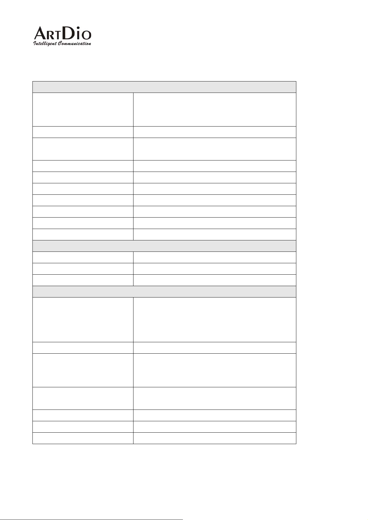
Voice Interface
Loop start, 2 wire
FXS interface
FXO interface Loop start, 2 wire
Connectors
Voice compression G.711/G.723/G.729AB
Silence suppression VAD, CNG
Echo cancellation G.165/G.168 16ms
Jitter buffer Adaptive jitter buffer management
Gain control In/Out +/-6db
Transport protocols RTP, RTCP
Call control protocol Pure SIP
Network Interface
Number of ports Two Ethernet ports
Interface 10BASE-T/100BASE-TX Auto-negotiation
Connectors RJ-45 Connectors
Feeding Voltage: 20V
Feeding Current: 30 mA
RJ-11 Connectors (3702/3704)
IDC Connectors (3708/3716)
General Spec
IPS 3702: 190mm x 110mm x 25 mm
Dimension
Power Voltage: 100-240 VAC, Frequency: 50/60 Hz
Power consumption
Working environment
EMI FCC part 15 Class B . CE Mark
PTT FCC part 68 , NALTE , iDA , JATE
Safety cUL , CCIB , CB
IPS 3704: 172mm x 177mm x 35 mm
IPS 3708: 440mm x 44mm x 254 mm
IPS 3716: 440mm x 66mm x 254 mm
IPS 3702: 8 W
IPS 3704: 12W
IPS 3708/3716: 70W
Operating temperature: 0 to 50℃
Storage temperature: -10 to 70℃
56
Page 57

IPS 1000 Series VoIP Gateway
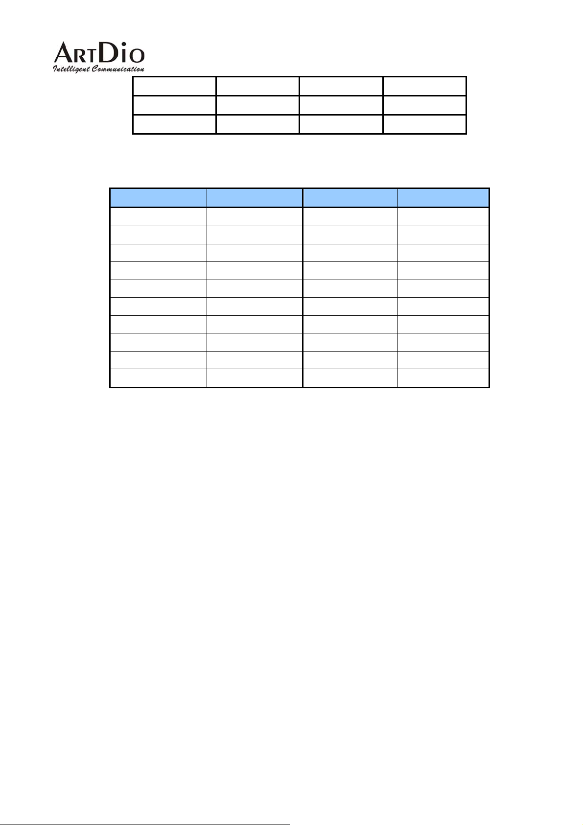
14.4. Mapping table of characters used in PPPoE
Character Digits to key-in Character Digits to key-in
0 30 X 58
1 31 Y 59
2 32 Z 5*0
3 33 a 61
4 34 b 62
5 35 c 63
6 36 d 64
7 37 e 65
8 38 f 66
9 39 g 67
@ 40 h 68
A 41 i 69
B 42 j 6*0
C 43 k 6*1
D 44 l 6*2
E 45 m 6*3
F 46 n 6*4
G 47 o 6*5
H 48 p 70
I 49 q 71
J 4*0 r 72
K 4*1 s 73
L 4*2 t 74
M 4*3 u 75
N 4*4 u 76
O 4*5 w 77
P 50 x 78
Q 51 y 79
R 52 z 7*0
S 53 = 3*3
T 54 . 2*4
57
Page 58
IPS 1000 Series VoIP Gateway
U 55 @hinet.net **01
V 56
W 57
14.5. Region ID
Country Region ID Country Region ID
Australia 02 Korea 24
Philippines 03 Malaysia 26
Canada 06 Singapore 36
China 07 Slovenia 38
Vietnam 10 Spain 40
France 12 Taiwan 43
Germany 13 Thailand 44
Hong Kong 15 British 46
Italy 22 USA 47
Japan 23
58
Page 59
IPS 1000 Series VoIP Gateway
15. Contact Information
If you have any question please feel free to ask our technical support, or visit our website
http://www.artdioinc.com
Taiwan
Add:7th FL.., No.476, Min-Hu RD., Hsin-Chu, Taiwan 300
TEL:+886-3-5295000
FAX:+886-3-5295005
E-Mail:[email protected]
Shang Hai
Add:No.8 775 Nong, Hang Dong RD., Shanghai China
TEL:+86-21-64216757 EXT.16
+86-21-64216758 EXT.16
FAX:+86-21-64216758
E-Mail:[email protected]
Los Angles Office
.
Address:14235 Lomitas Ave. La Puente, CA 91746
TEL:+1-626-336-0369
FAX:+1-626-961-9114
Email:[email protected]
59
 Loading...