

Page 1
The Voice Gateway
User Manual
IPE 1000 Series
version:1.0 update date:2004/1/2
ARTDio Company Inc.
Page 2

Terminology
¾
FXS interface: A Forei gn Exchan ge Station (FXS) interface is used to connects to a st anda rd telephone, fax
machine, trunk side of PBX, or to other FXO interfaces. It will supply ring, voltage, and dial tone. So it is very
important not to connect the FXS interface to the wrong device that are not listed above, it will damage the
voice gateway or the voice gateway will damage the device on the other end.
¾
FXO interface: A Foreign Exchange Of fice (FXS) interface is used to make a connectio n to be directed at the
PSTN central office or to a analog PBX extension line. It will supply hook off, hook on and flash signal that act
like a standard analog phone. On the contrary with FXS interface, FXO do not have line power on it.
¾
Access Code: A use r defined string of digit s, st ands for access dif ferent voice p ath, call control or to activa te
special function for making a call. For example, users can define the access code to make a transit call, a
circuit connect call or a MGCP call.
¾
Soft Key: A string of digits defined for each channel, that this soft key will be send out or activated while detect
the pre-defined trigger events for this channel. Sof t key can alos be activated with a pre-defined access code.
¾
Circuit Connect: A special function provide by PBX gateway, while applying this function the channel from
caller to the channel of called party is connected as if there was a real circuit line between. After the
connection is made, all the number user dial will be send to the other side transparently.
¾
MGCP: MGCP (Media Gateway Control Protocol) is a protocol for the call control of Voice over packet
networks by out-of-band call-control elements known as media gateway controllers (MGCs) or call agents
(CAs). It is described in the IETF RFC2705.
¾
FXO Outgoing Prefix: A prefix (num bers that can allow p ause key) that will be send out from FXO interfaces
before any number. This is used while voice gateways are connected to PBX extension lines with FXO
interfaces.
¾
T.38 Fax Relay: T.38 fax relay is a ITU standard that allow fax b eing transmitted over IP service network. Differ
from T.37 store and forward fax relay that T.38 is defined for real time fax transmission.
2
Page 3

Table of Contents
1.INTRODUCTION .................................................................................................................. 6
1.1 Functions of the PBX VoIP Gateway .........................................................................................................................6
1.1.1 Removes the heterogeneous PBX system barrier.........................................................................................................6
1.1.2 Enables Toll-Bypassing advantages..............................................................................................................................6
1.1.3 Foreign Exchange Advantages.....................................................................................................................................7
1.1.4 Hot-Line Application....................................................................................................................................................7
1.1.5 T elecommuter Application............................................................................................................................................8
2. BASIC APPLICATIONS OF THE PBX VOIP GATEWAY............................................... 9
2.1 Internal Calls ...............................................................................................................................................................9
2.2 Calling From Stations To Remote PSTNs................................................................................................................10
2.3 Calling From PSTNs to internal Stations ................................................................................................................10
2.4 Transit Calls From PSTNs to Remote PSTNs.........................................................................................................11
3. QUICK INSTALLATION................................................................................................ 13
3.1 Quick Start.................................................................................................................................................................13
3.2 Basic Topology ...........................................................................................................................................................13
3.3 Working Under a NAT Networking Environment..................................................................................................16
3.4 Utilizing QoS advantages.........................................................................................................................................18
3.4.1 Connectors and LED Indicators.................................................................................................................................19
3.5 Initial configuration of the Gateway........................................................................................................................22
3.5.1 Using the System Console..........................................................................................................................................22
3.6 IP Configuration........................................................................................................................................................24
3.6.1 Assigning the User IP Address ...................................................................................................................................24
3.6.2 Obtaining an IP Address From a DHCP Server..........................................................................................................26
3.7 Configuring the Master Device.................................................................................................................................28
3
Page 4

3.8 Adding A New Slave Device to the Group...............................................................................................................30
4. BASIC CONFIGURATION............................................................................................ 35
4.1 System Console Modes..............................................................................................................................................35
4.2 System Management .................................................................................................................................................35
4.2.1 Information-Web Management...................................................................................................................................36
4.2.2 Console Commands -Sy st em Information..................................................................................................................38
4.2.3 Registration-Web Interface.........................................................................................................................................39
4.2.4 Registration Information- Console Interface..............................................................................................................42
4.2.5 Configuration-Web Interface......................................................................................................................................42
4.2.6 Configuration Information- Console Interface...........................................................................................................44
4.2.7 Numbering Plan-Web Interface..................................................................................................................................45
4.2.8 Numbering Plan Information- Console Interface.......................................................................................................48
4.2.9 International Code-Web Interface...............................................................................................................................49
4.2.10 International Code Information- Console Interface..................................................................................................50
4.2.11 Long Distance Code-Web Interface..........................................................................................................................51
4.2.12 Long Distance Code Information- Console Interface...............................................................................................52
4.2.13 Routing Table-Web Interface....................................................................................................................................53
4.2.14 Routing Table- Console Interface.............................................................................................................................54
4.2.15 Pin Code Assignment-Web Interface........................................................................................................................55
4.2.16 Pin Code Assignment- Console Interface.................................................................................................................56
4.2.17 Topology-Web Interface ...........................................................................................................................................57
4.2.18 Topology- Console Interface ....................................................................................................................................57
4.2.19 Route Search-Web Interface.....................................................................................................................................58
4.2.20 Route Search- Console Interface..............................................................................................................................58
4.2.21 MGCP C on fi guration - Web Interface......................................................................................................................59
4.2.22 MGCP Configuration - Console Interface................................................................................................................59
4.3 TCP/IP Configur ation...............................................................................................................................................60
4.4 Channel Management...............................................................................................................................................62
4.4.1 Summary....................................................................................................................................................................62
4.4.2 Regional .....................................................................................................................................................................64
4.4.3 Channel Configuration...............................................................................................................................................67
4.4.4 Statistics......................................................................................................................................................................70
4
Page 5

4.4.5 Call Status...................................................................................................................................................................72
4.5 Management Interfaces.............................................................................................................................................73
4.5.1 Web Management.......................................................................................................................................................73
4.5.2 Console Commands....................................................................................................................................................75
4.6 Software Upgrade......................................................................................................................................................76
4.6.1 Console Commands....................................................................................................................................................78
4.7 Additional Console Commands................................................................................................................................79
5. PHONE SET INTERFACE CONFIGURATION PROCEDURES................................... 81
5.1 Configuration procedures.........................................................................................................................................81
5.2 Greeting Message Recording Procedur e.................................................................................................................82
5.3 Configurable Items....................................................................................................................................................83
5.3.1 Data Range.................................................................................................................................................................83
5.3.2 Configurable Items.....................................................................................................................................................83
6. FIREWALL CONFIGURATION..................................................................................... 85
7. REGULATION COMPLIANCE INFORMATION ........................................................... 87
7.1 FCC.............................................................................................................................................................................87
8. REGIONAL TONE ADJUSTMENT............................................................................... 88
9. FTP FOR SOFTWARE UPGRADING, CONFIGURATION AND GREETING MESSAGE
UPLOADING/DOWNLOADING ............................................................................................ 89
10. THE CALL DETAIL RECORD INFORMATION............................................................ 90
5
Page 6
1.Introduction
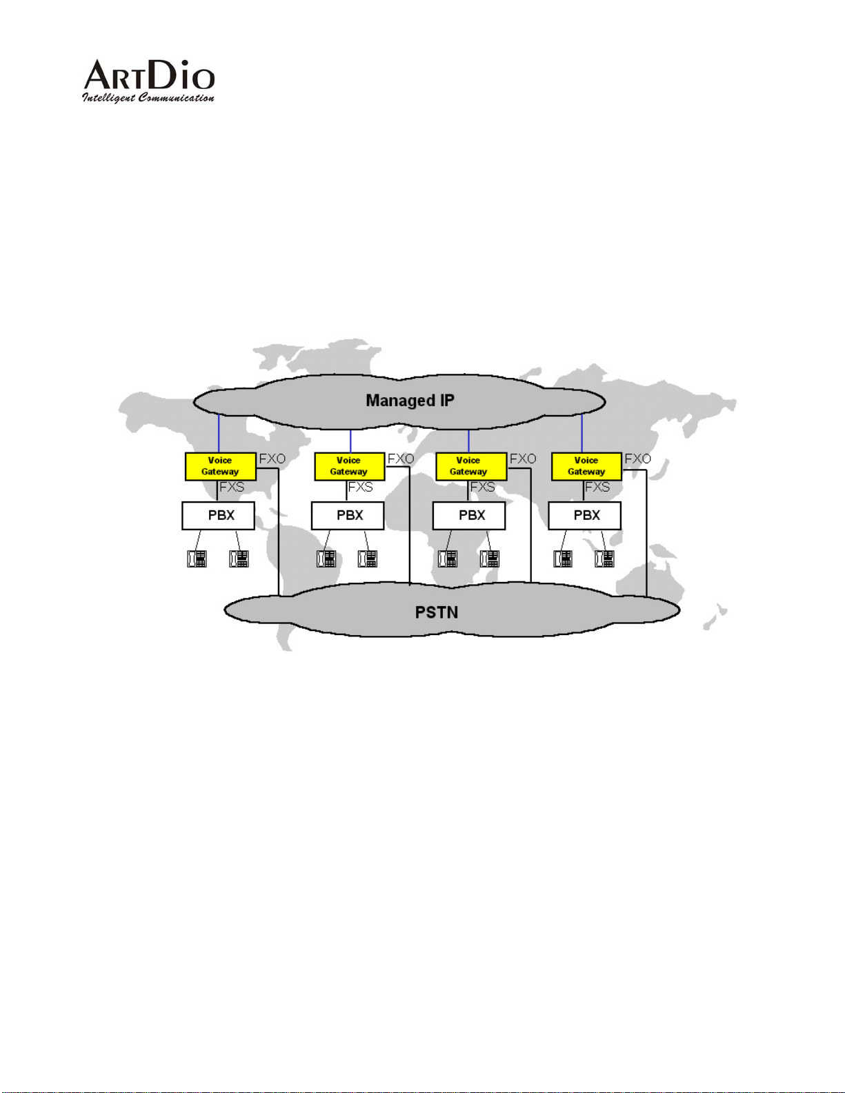
This guide explains how to configure the PBX VoIP gateway using the system console commands and web
management interface. This manual is designed for the technicians respo nsible for configu ring the gateway.
The candidates should have technical networking background and PBX VoIP gateway experience. They
must also have a working knowledge of VOIP fundament als.
1.1 Functions of the PBX VoIP Gateway
1.1.1 Removes the heterogeneous PBX system barrier
For multi-national enterprises or companies that have multiple office s located at different sites, it is dif ficult
to have a mutual interoperable PBX system for the whole group of offices. For it is difficult to have all
related offices using the same PBX system or even one that is compatible.
The PBX VoIP gateway is designed for functioning as the PBX tie trunk as well as maintaining
interoperability with different PBX or KTS systems.
1.1.2 Enables Toll-Bypassing advantages
The PBX VoIP gateway utilizes modern V oIP technology, enabling toll-bypassing advantages with flat rate
data access fees. This can save an enormous expense, especially for a large amount of phone
communication hours between office s.
6
Page 7
1.1.3 Foreign Exchange Advantages
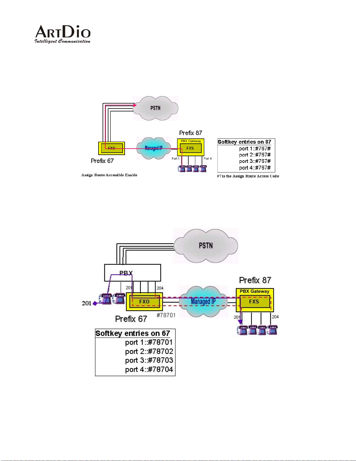
The toll-free advantage can also be extended to access remote PSTNs. A Company can set up a PSTN
line in a remote office in a foreign country. Domestic users can then access the remote PSTN through the
PBX gateway while paying local or long distance phone rates instead of International phone rates.
1.1.4 Hot-Line Application
With the soft key and circuit connect function, it is easily to implement the hot-line application. The remote
office can accesses to the PBX in headquarter as if it is in main office.
7
Page 8
1.1.5 Telecommuter Application
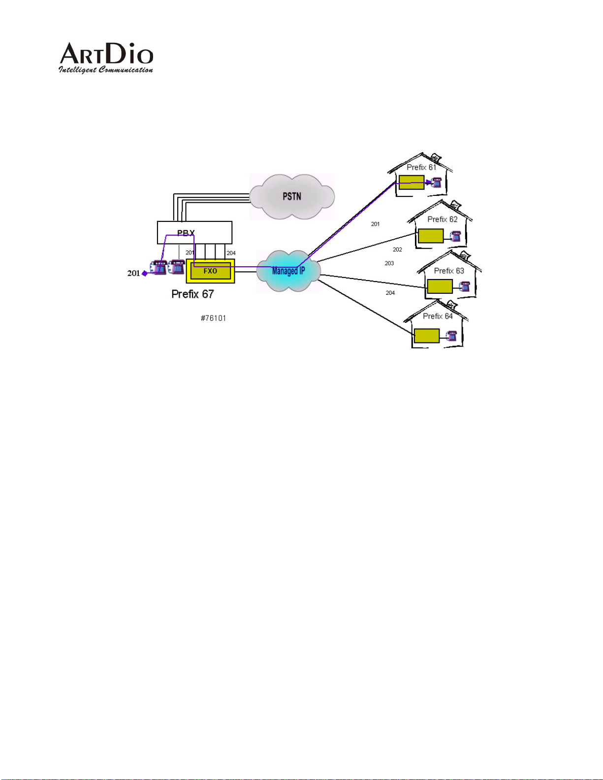
In a company, some of the people are asked to travel around or work at home. With PBX gateway, can
provide the application to allow the user take a small box travel around or install in home, the user can
receive the phone that call to his desk wherever.
8
Page 9
2. Basic Applications of the PBX VoIP Gateway
2.1 Internal Calls
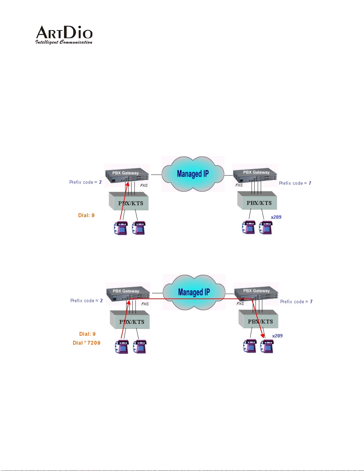
The VoIP Gateway is designed to be the tie trunk of the PBX, which means that when two or more PBXs are
tied with VoIP connections, the extension line on the remote PBX will function as an extension of the local
PBX. The following graphic is an example of this concept. The user at the extension on the PBX VoIP
gateway with the prefix code "2" can dial "9" plus "*7209" to connect to extension 209 of the PBX that has
the PBX VoIP gateway with the prefix "7", where “9” is the trunk group select code of PBX.
9
Page 10
2.2 Calling From Stations To Remote PSTNs
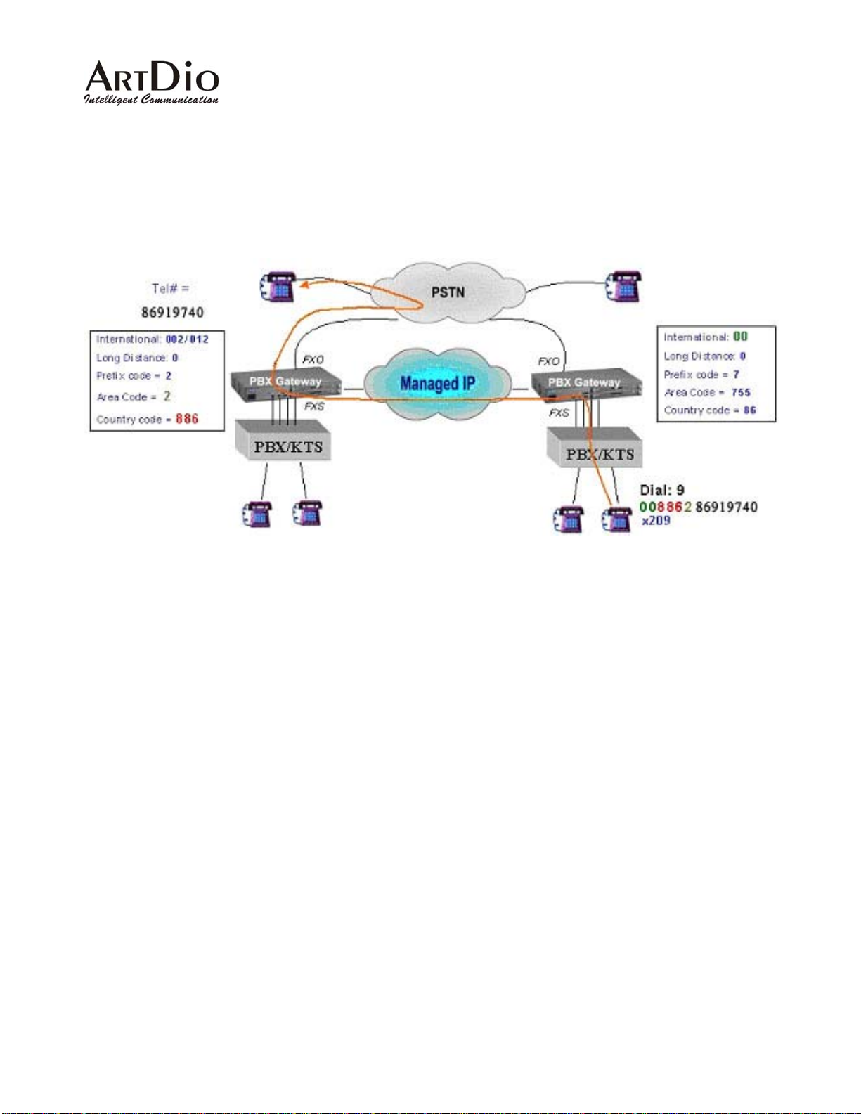
PBX VoIP gateways that have the FXO interface are able to make phone calls from extensions of the PBX
to remote PSTN users through an IP network. The foll owing example demonstrates how a user on
extension "209" at an office in Shenzhen , can communicate with a user in Taipei with the phone number
"886-2-8691-9470" via a PSTN by picking up his desk phone and dialing "9" plus "00886286919740".
Fig 1 Call From Local Station to Remote PSTN
2.3 Calling From PSTNs to internal Stations
The PBXs are tied as a group, therefore the internal station at this location will have (I). Local station: the
stations collocated with the PBX VoIP gateway that PSTN users dial in to. (II). Remote station: the station
that is on the other PBX VoIP gateway that is connected to the IP network.
To call the local station, the PSTN user can dial the main office number "2 322-2222", after hearing the
greeting message, the user would dial "508" so that the phone can connect to extension 508 of the local
PBX. To call the remote station, the local PSTN user can dial the main office number "2322-2222". After
hearing the greeting message, the user would dial "*7209" so that the phone can connect to extension 2 09
of the remote PBX.
10
Page 11
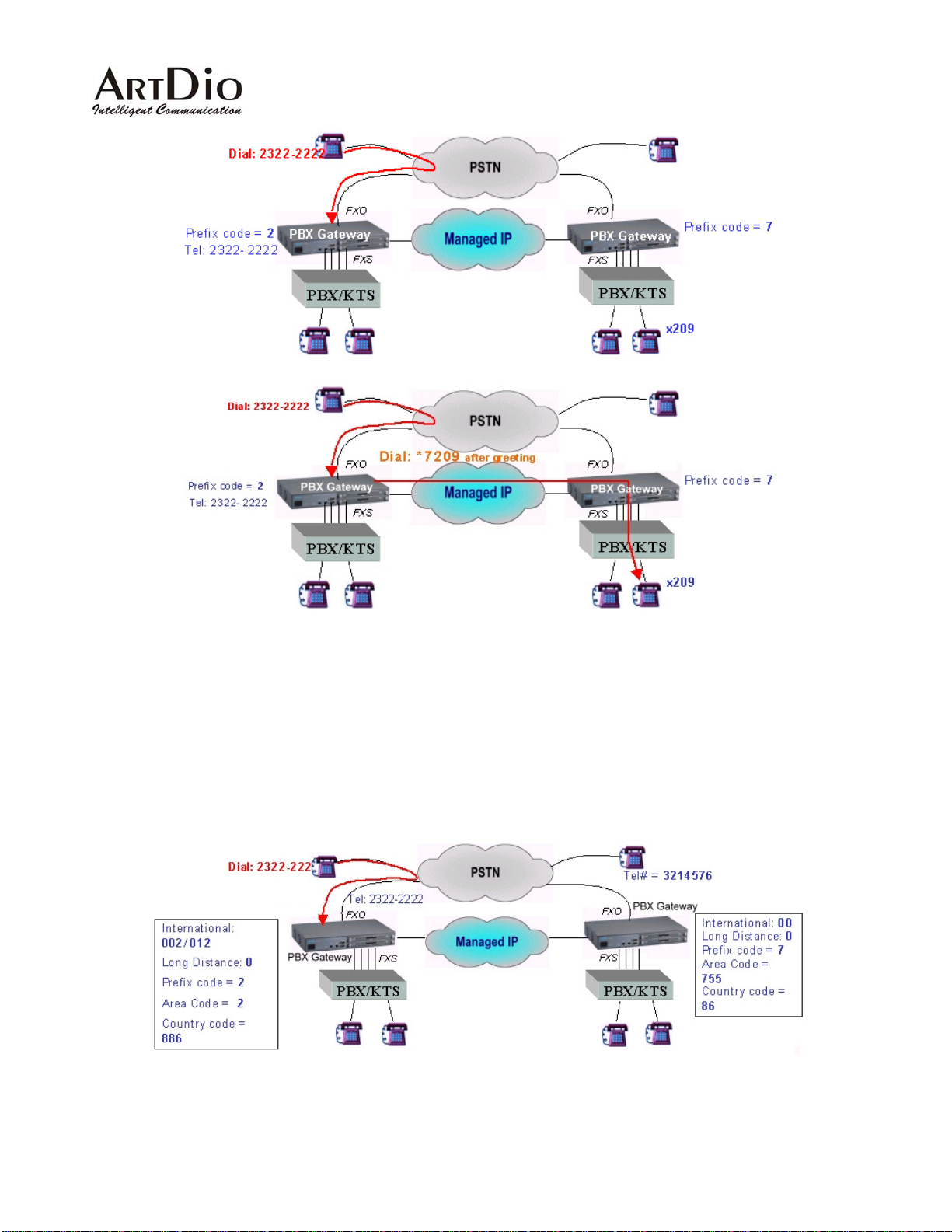
Fig 2 Example of calling from PSTN to internal stations
2.4 Transit Calls From PSTNs to Remote PSTNs
The following example is designed for telecommuters or administrative users that need to access the
remote PSTN in another office. This application allows the user to call from a local PSTN to a remote PSTN
through the PBX VoIP gateway. To maintain company security, the PBX VoIP gateway requires that a pin
code be entered before a transit call is placed.
11
Page 12
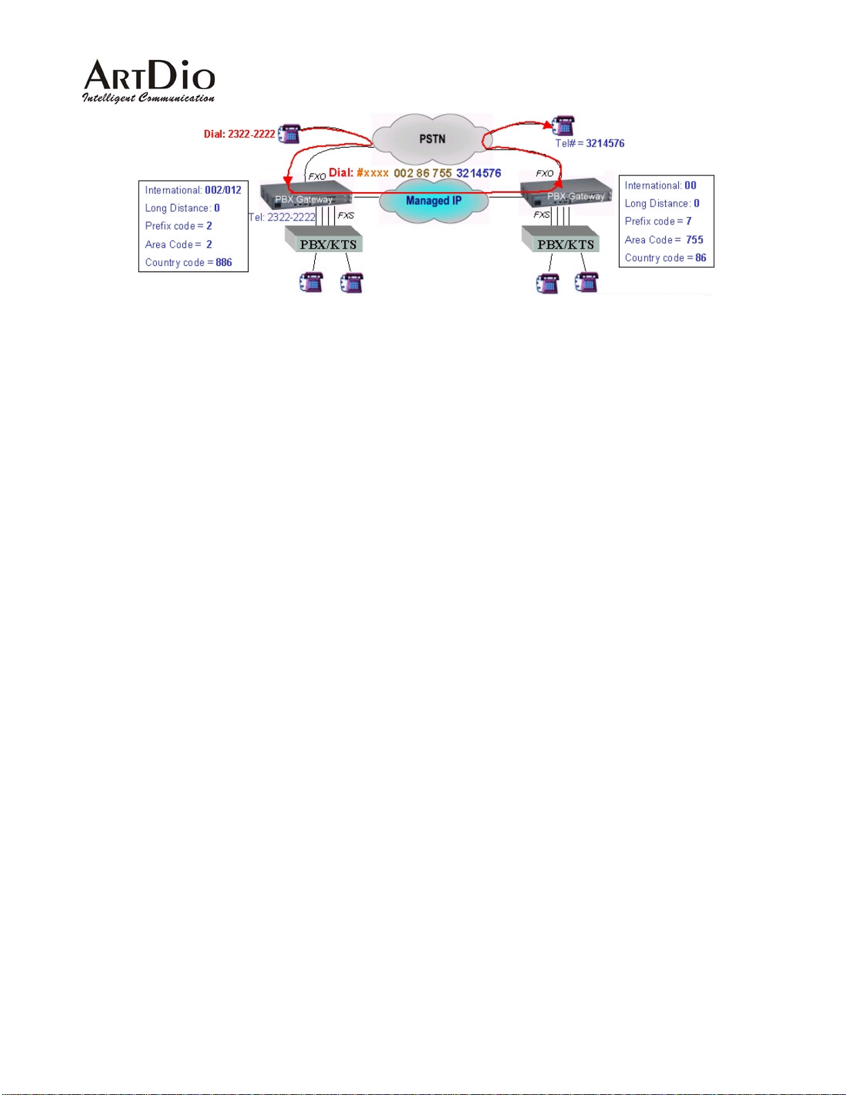
Fig 3 Example of making transit calls from PSTNs to remote PSTNsQuick Installation
12
Page 13

3. Quick Installation
3.1 Quick Start
1. Plug in the Ethernet Cable, Null Modem cable and switch on the device to begin the configuration
procedure.
2. Configure the IP Address, subnet mask, Default Gateway to make the device reachable from the
network.
3. Configure the device’s prefix .
4. Decide the role (master or slave) of the device and configure the Group ID.
5. Add the MAC address of the slave that will join the group to the master.
6. Configure the IP address of the master gateway to the slave device.
7. Restart the device so that the configuration cha nges can take effect.
3.2 Basic T opology
The PBX VoIP gateway is based on master/slave architecture, which means the gateway will work with a
group of slave gateways as a master gateway or join a group that is registered on a particul ar master
gateway. The master gateway is the core of all common and control information in the same group.
The master keeps a list of all the members of the group, while keeping the whole gro up’s
information updated by polling each slave device with routing information and group table. As a
result of this function, when a new device joins the group, it will receive the entire group’s
information from the master. The other members in the group will then also be updated.
A new slave must join the group by synchronizing the group information with the master device.
Unless this step is completed, the slave cannot be used to make phone calls to any other devices.
After a slave joins the group, it will receive a member list of the entire local group. The device can
now make calls to other slave devices even if the master device loses its connection (the Ready
LED light is off). However if the master device has lost its conne ctio n, it will be unable to re ceive
new slave updates .
Each device in the group will have a common prefix number as an ID for the entire group.
The Master also play the role as Real IP Resolver for t he Salves that work under NAT environment
to find its real IP address and port number in the publi c IP network.
The PBX VoIP gateway is designed to work over an IP network. Before it connects to an IP network, you
must assign the Gateway an IP address. Like the regular settings of an IP network, you also need to
configure the subnet mask and the default gateway. The different aspects in configuring the master and
slaves begin after the initial IP address configuration has been completed.
13
Page 14
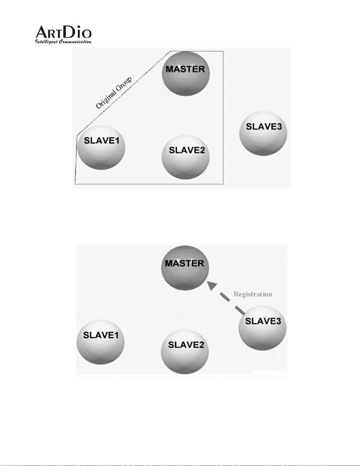
Fig 4 The master is responsible for maintaining the member list
Fig 5 When a new Slave is added to the group registrar.
14
Page 15
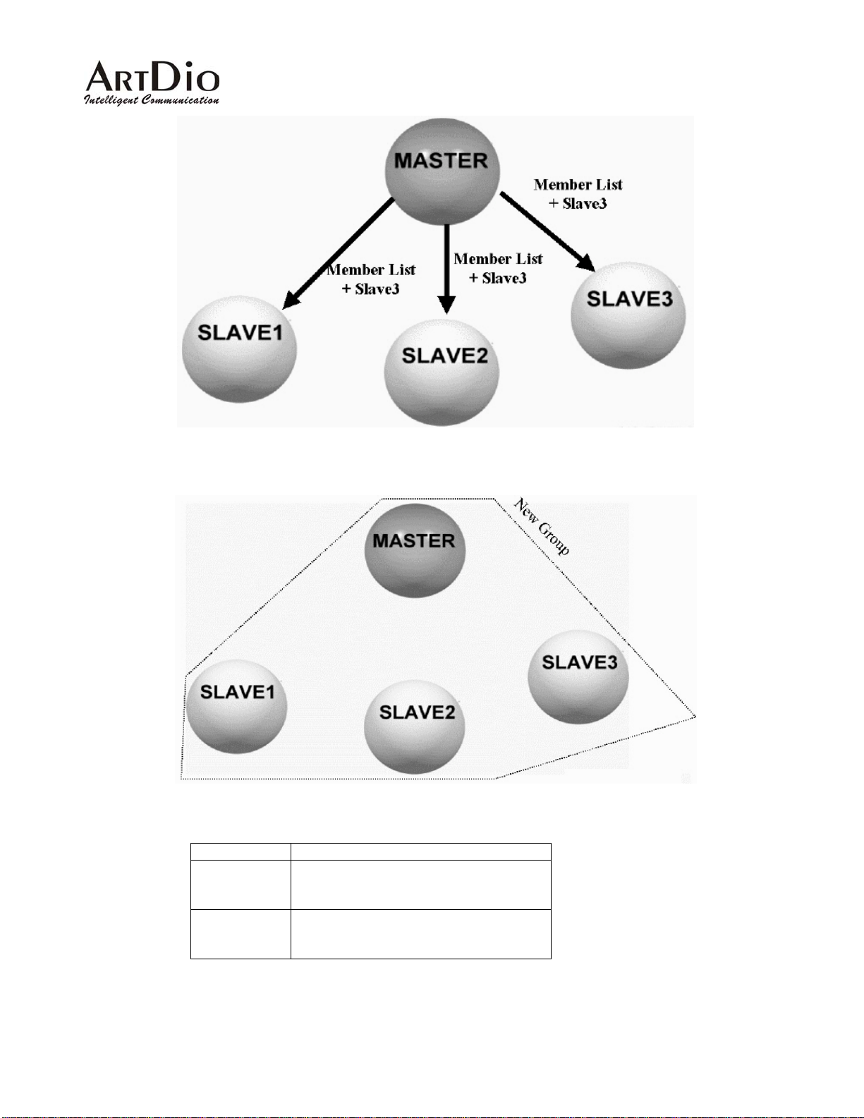
Fig 6 The master updates the new member list and sends it to each mem be r
Fig 7 The master will synchronize the member information with each member.
Device Role MUST Parameters
Master
Prefix
Group ID
MAC address of Slave devices
Slave
Prefix
Group ID
IP address of Master Device
Note 1 If a slave has successfully joined the group; the ready LED will be lit.
15
Page 16
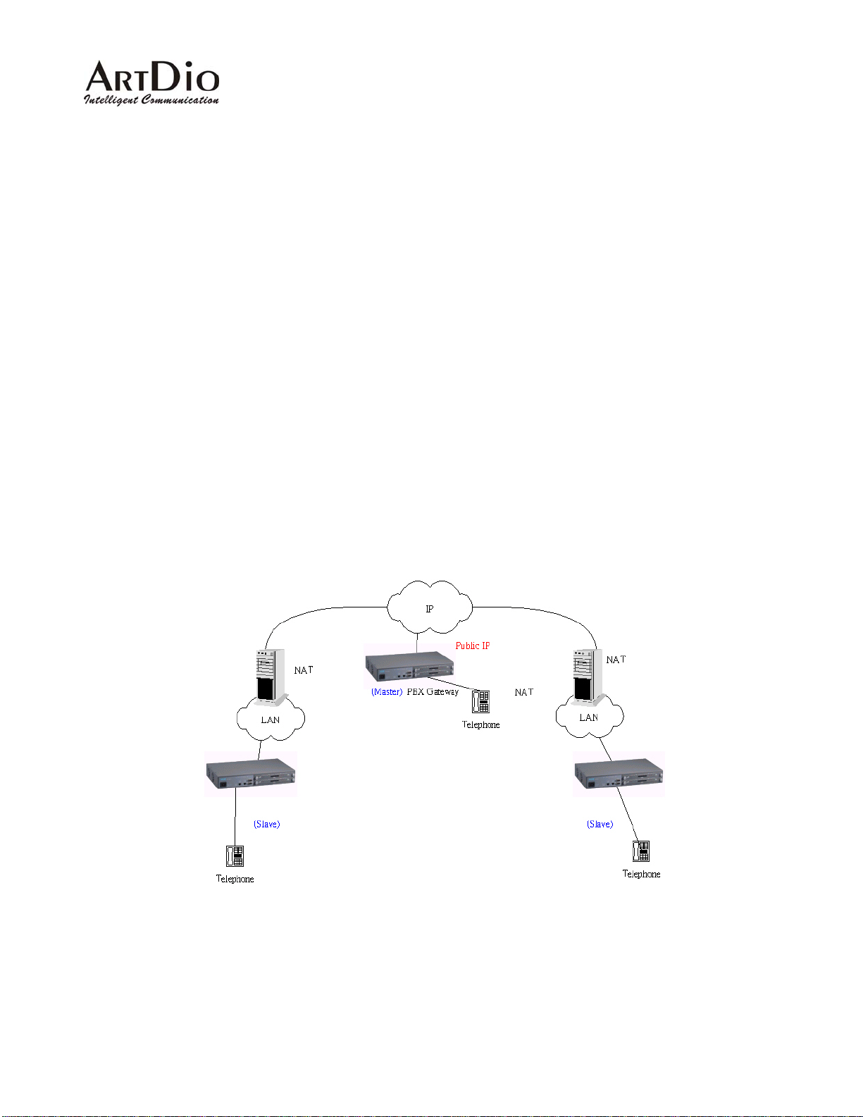
3.3 Working Under a NAT Networking Environment
IP addresses are limited; because of this, not all devices on the Internet can have their own public IP
address. An application is available that allows users to use a private IP address by utilizing a NAT (Network
Address Translation) server. When t he packets are sent out from the local area net work, the IP header will
be replaced with a public IP address. This is very useful in conserving IP address usage on the Internet.
Most VoIP devices cannot support NA T , since NAT servers only replace the IP headers. However , VoIP
packets have IP information in the data area of every voice packet. So while the voice packet has been
replaced with a real IP header, the data inside is still using a private IP address.
The PBX Gateway is able to use private IP addresses by applying NAT. Most of time, you will not need to
change any configuration settings on the NAT server or even on the PBX Gateway itself. The one essential
condition is that the master device of the group should use a public IP address.
Since there are currently so many NAT servers on the market , there is no set standard in addressing how
to develop NA T servers or how to test the interoperability of NA T servers with other applications. Therefore,
depending on your NAT server, you may have to adjust some of the configurations to specify the
In-bound/Out-bound rules in order to give your NAT server the ability to work with various special
applications.
Fig 8 Supports VoIP under a NA T environment
Guaranteed only for tested NAT servers or software
Some of the NAT configuration settings need to specify the In-bound/Out-bound rules, however
16
Page 17

some settings do not need an adjustment on the NAT server, such as the SMC barricade
The master must have a public IP address
Only one slave device with a private IP address may be installed on each NAT domain. This
means that cascading to increase the density of channels by using private IP addresses is not
supported
Some In-bound/Out-bound address translation rules may time out on a NAT server. In this
instance, users may need to restart the voice gateway.
Management Interfaces under NAT
Since the device works with private IP addresse s, users cannot access the management interfaces (W eb or
Telnet) from the Internet if they do not specify the redirection settings on the NAT server. Even if you are
able to specify redirection rules to redirect these (Web or Telnet) requests to the voice gateway , some of the
well known ports (such as TCP port 80 for W eb, TCP port 23 for Telnet and TCP port 21 for FTP) will already
be occupied by public servers that are using private IP addresse s. In this instance , you will ne ed to change
the port numbers to gain access to the voice gateway as well as to maintain public access to internal
servers. You will then need to change the service port numbers for Web and Telnet on the voice gateway.
The commands are as follows (you can only use Telnet or Console to modify the service port information):
1. Show the current service port information
PBX Gateway>enable
PBX Gateway#show service_port
FTP Service Port: 21
Telnet Service Port: 23
Web Service Port: 80
PBX Gateway#
2. Modify the service port
PBX Gateway#config
Enter configuration commands, one per line. End with CTRL/Z
PBX Gateway(config)#service port
PBX Gateway(config)#service_port ?
ftp Set ftp service port number
telnet Set telnet service port number
web Set web service port number
PBX Gateway(config)#service_port web <new port number i.e.88>
17
Page 18
3.4 Utilizing QoS advantages
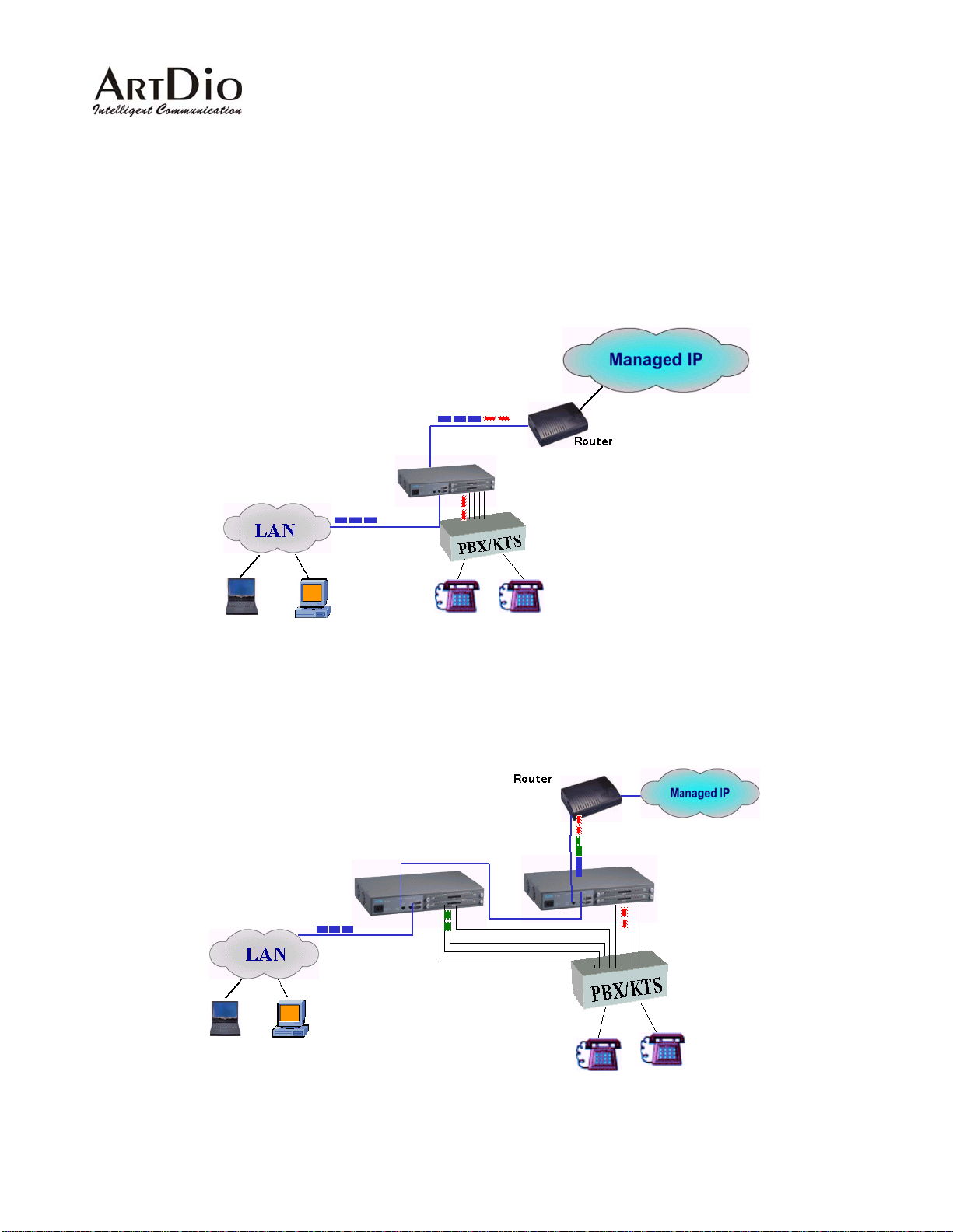
The PBX voice gateway is equipped with QoS capabilities. This provides higher priority for voice than data
from the LAN. However you must install the device according to the following diagram in order to give voice
output a higher priority than data output from a LAN. The "To WAN" Ethernet port on the front panel is used
to connect to the router. The "To LAN" Ethernet port that is near the RS-232 port on the front panel is used
to connect to the HUB or Switch on the LAN. This will give voice output a higher priority than data output.
Fig 9 Diagram shows the utilization of embedded QoS capabilities. To maintain QoS functions while
stacking the devices, you need to connect the LAN port of the primary PBX gateway (that connects to the
router) to the WAN port of the secondary PBX gateway. Likewise the LAN port of the secondary PBX
gateway connects to the HUB or Switch on the LAN.
18
Page 19
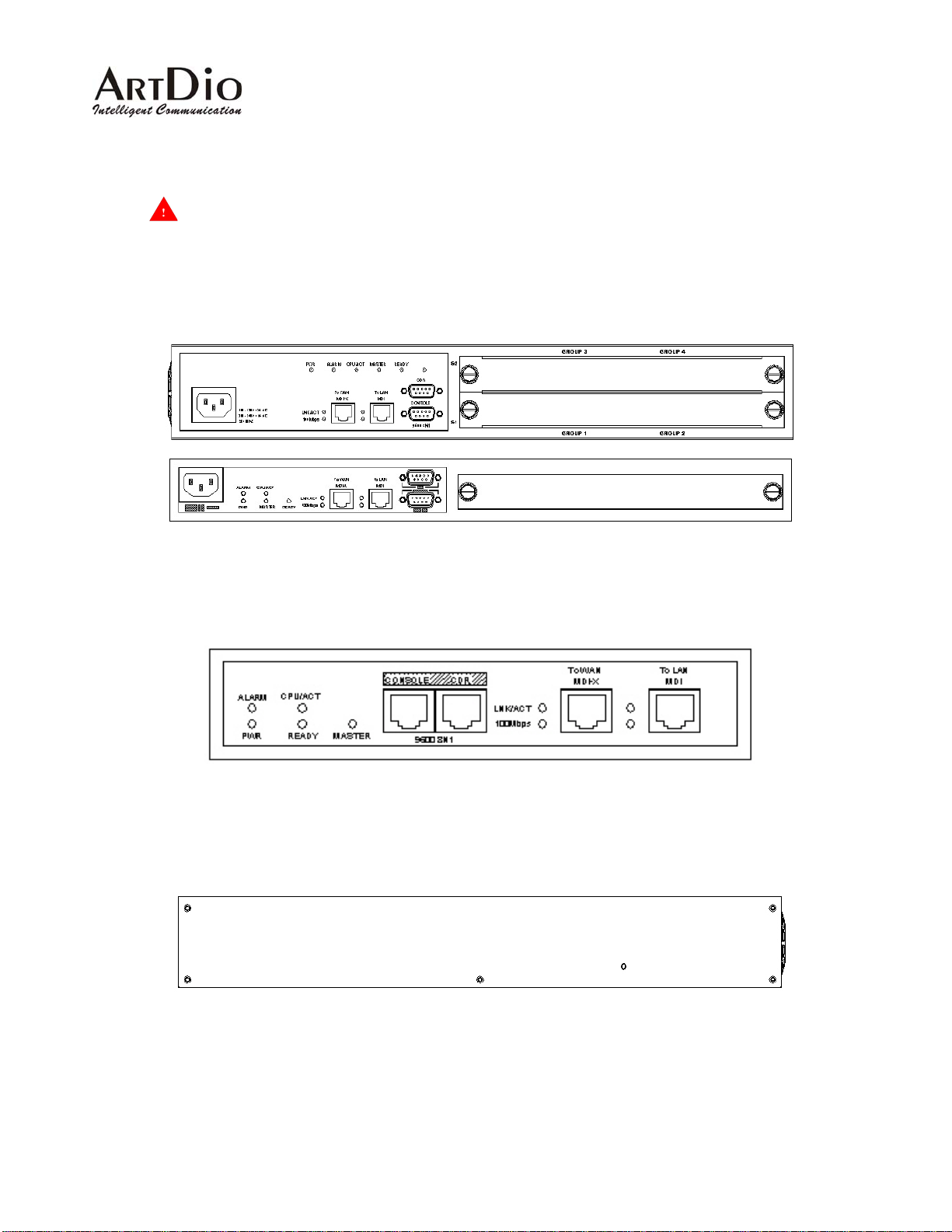
Fig 10 Diagram showing utilization of embedded QoS functions while stacking the devices
3.4.1 Connectors and LED Indicators
WARNING: Please ensure that the cables that will be connected to the FXS interfaces on the PBX
VoIP
gateway are not connected to any power source ("0" voltage).
Front Panels
19-inch model
-inch models 7
s
Fig 11 19-inch models Front Panel
Rear Panels
19-inch 1.5U
model
Fig 12 7-inch model Front Panel
Fig 13 19-inch model Rear Panel
19
Page 20
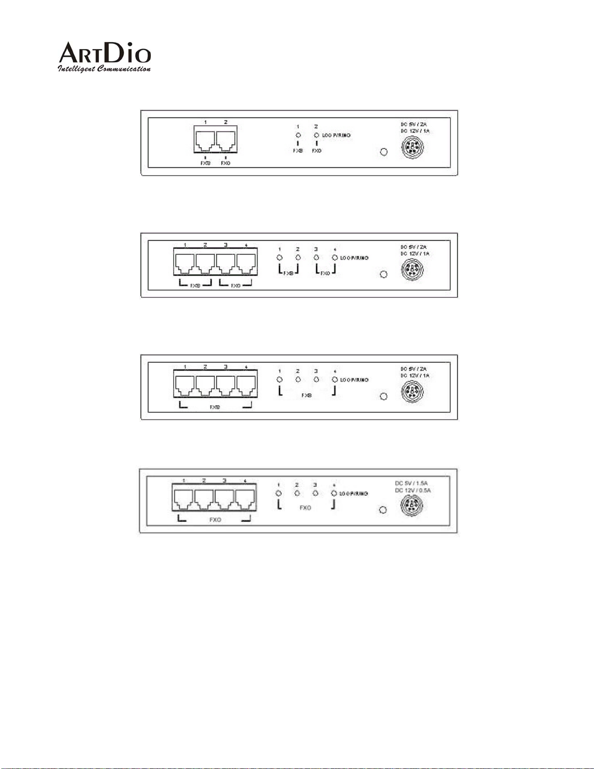
1 FXS and 1 FXO Model
2 FXS and 2 FXO Model
4 FXS Model
4 FXO Model
Fig 14 7-inch model Rear Panel
20
Page 21
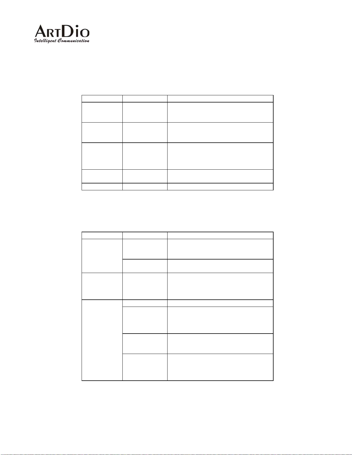
Connectors Description
Connectors Type Description
To WAN
10/100
RJ45 with MDI-X onnect to the Ethernet port Designed to c
on the router.
Ethernet
To LAN
10/100
RJ45 with MDI nnect to one of the LAN’s Designed to co
HUB/Switch ports.
Ethernet
EIA-232
DB-9 DTE a VT100 terminal or Can be connected to
system console. The terminal should be
configured to 9600 baud, 8 bits, 1 stop
bits and none parity check.
POTS Ports
Power
IDC Jack or
RJ-11 jack
AC 90-120 Volt, 220~250Volt
Where analog telephone lines are
connected
ED Description
L
LED Label Description
10/100
Etherne
t
LNK/ACT ates a network connection. When lit, indic
The LED will flash when network traffic is
detected.
100Mbps
Indicating the network is running at
100Mbps
Port
Inform
ation
LOOP/
RING
When lit, indicates a loop has been
detected. Flashing indicates an outg
call on the FXS interface or an incoming
call on the FXO interface.
Device
Power Indicates stable power.
Alarm The device will halt and the indicator will
stay lit if a system test failure is detected,
or if there are loop current lost counted on
FXO interfaces.
Master If this device is configured as the master,
this green LED will be on. If configured as
a slave , it will remain off .
Ready
This green LED will be on when this
device is configured as the master or
configured as a slave , is connected with
the remote master.
oing
if
21
Page 22

3.5 Initial configuration of the Gateway
You must configure the Gateway to allow you to distinguish multiple PBX VoIP gateways from each other.
You may also want to configure a password for the gateway to prevent any unauthorized access.
3.5.1 Using the System Console
The following process shows how the host name and password ca n be configured via the system console.
Before you begin, make sure to perform the following:
y Connect a VT100 terminal to the console port: 9600, 8, 1, N
y Switch on the gateway and wait until it displays ”Press Enter…”
Step 1: Enter Privileged Mode
PBX GATEWAY>enable
Password: ******
PBX GATEWAY#
There is no (factory default) password set
Step 2: Enter configuration mode
PBX GATEWAY#configure terminal
Enter configuration commands, one per line. End with CTRL/Z
PBX GATEWAY (config)#
Step 3: Modify the name of the gateway for easy reference
PBX GATEWAY (config)#hostname PBX Gateway
PBX Gateway (config)#
Step 4: Change the privileged mode pa ssword.
PBX Gateway (config)#password console read <password>
To configure the password for read-only privilege
or
PBX Gateway (config)#password console write <password>
22
Page 23

To configure the password for read and write privileges
The privileges are divided into read-only and read-write with a different password for each privilege.
After you have issued this command, you will then be asked to enter this password each time you enter
privileged mode. Any combination of characters and digits are allowed with a maximum of 6
characters/digits. Here is an example:
PBX Gateway (config)#password read console psw
PBX Gateway (config)#
23
Page 24

3.6 IP Configuration
Y ou must configure the IP address, subnet mask and default gateway so that the PBX VoIP Gateway is able
to connect to the IP network. Since the device provides a 10BASE-T/100BASE-TX Ethernet interface with a
default auto-negotiation setting, it should work like a plug-and-play device; therefore a manual configuration
should seldom be necessary.
The system provides two types of IP assignment:
1. Manually assigned (static)
2. DHCP server assigned
Y ou can use the IP state command to select the app ropriate mode that is used by your network. The default
value is set to manually assigned. On the first time of setting up the gateway, you must assign the IP
address manually. If you want the gateway to receive the IP address from a DHCP server, you must set the
IP state mode to DHCP mode. If a DHCP server is used, it will request the IP address from the server.
1
However, if the DHCP server does not respond within one minute, the system will attempt to use the
manually assigned IP address.
Please note that when the system is in DHCP mode, the IP address received from the DHCP server
will be saved in the configuration file, so if the PBX Gateway is unable to request an IP address
from the DHCP server during the next boot up, this IP address will then be used.
Modifications will not take effect until after your system is restarted .
3.6.1 Assigning the User IP Address
Using the System Console Interface or Telnet
Step 1: Enter privileged mode
PBX GATEWAY>enable
Password: ******
PBX GATEWAY#
Step 2: Enter Configuration Mode
1
While operating under a NAT environment, it is better to have a static IP address and redirect the port number to this static IP to provide
remote managed access from the Internet.
24
Page 25

PBX GATEWAY#configure
Enter configuration commands, one per line. End with CTRL/Z
PBX GATEWAY (config)#
Step 3: Assign the IP address and the subnet mask
Command: PBX GATEWAY (config)#ip address <ip-address> <subnet-mask>
PBX GATEWAY (config)#ip address 203.79.238.144 255.255.255.128
System must then be restarted
PBX GATEWAY (config)#
Step 4: Assign the default gateway
Command: PBX GATEWAY (config)#ip default-gateway <address>
PBX GATEWAY (config)#ip default-gateway 203.79.238.186
PBX GATEWAY (config)#
Step 5: Save the configuration to non-volatile memory immediately. If you power the device off
immediately, your new configurations will be lost when you switch the power off. However, the system
will automatically save the configuration if no input has been detected within one minute.
PBX GATEWAY (config)#dbflush
PBX GATEWAY (config)#
Step 6: Switch back to privileged mode
PBX GATEWAY (config)#exit
PBX GATEWAY#
Step 7: You must now restart the system in order for your changes to take effect. After the restart
command is issued, the system will prompt for a confirmation.
PBX GATEWAY#restart
This command resets the system. System will restart operation code agent.
Reset system, [Y]es or [N]o? Yes
25
Page 26

Using Phone Set Interface
Step 1: Take the handset off the phone
Step 2: Dial the PROG Access Code after hearing the dial tone (default is ##)
Step 3: Enter the Password (default is 0000)
Step 4: Enter code "02".
Step 5: Enter the IP address as "203","*","79","*","238","*","144" and "#" as the ending
prompt. You will then hear the confirmation tone.
Step 6: Enter code "03" to begin the subnet mask configuration.
Step 7: Enter the subnet mask as "255", "*", "255", "*", "255", "*", "128" and "#" as
the ending prompt. You will then hear the confirmation tone.
Step 8: Enter code "04" to begin configuring the IP address for th e default gateway.
Step 9: Enter the IP address of the default gateway as "203", "*", "79", "*", "238", "*",
"186" and "#" as the ending prompt. You will then hear the confirmation tone.
System must now be restarted
Step 10: Enter code "98" then press "1" and "#" as the ending prompt. You will then hear the
confirmation tone, and the system will restart automatically.
Place the handset on the phone to end your configuration session.
3.6.2 Obtaining an IP Address From a DHCP Server
Using System Console Interface
Step 1: Enter Privileged Mode
PBX GATEWAY>enable
Password: ******
PBX GATEWAY#
Step 2: Enter Configuration Mode
PBX GATEWAY#configure
Enter configuration commands, one per line. End with CTRL/Z
26
Page 27

PBX GATEWAY (config)#
Step 3: Enable DHCP Mode
PBX GATEWAY (config)#ip state dhcp
PBX GATEWAY (config)#
Step 4: Back to Privileged Mode
PBX GATEWAY (config)#exit
PBX GATEWAY#
Step 5: Restart the system to enable DHCP mode. After the restart com m and is issued, the system
will prompt for a confirmation.
PBX GATEWAY#restart
This command restarts the system. The system will now restart operation code
agent.
Reset system, [Y]es or [N]o? Yes
Using Phone Set Interface (please refer to the Phone Set Interface Configuration Procedures for
more detailed information)
Step 1: Take the handset off the phone. Step 2: After hearing the dial tone dial the PROG Access
Code.
Step 3: Enter the Password.
2
Step 4: Enter code "01" to begin configuring the DHCP state.
Step 5: Enter "1" to enable DHCP client and "#" as the ending prompt. You will then hear the
confirmation tone. (Or enter "0" to disable the DHCP client and "#" as the ending prompt).
System must now be restarted
Step 6: Enter code "98" then press "1" and "#" as the ending prompt. You will then hear
the confirmation tone, the system will then restart automatically.
Place the handset on the phone to end your configuration session.
2
The (default) password for the Phone Set Interface is "0000".
27
Page 28

3.7 Configuring the Master Device
Using the System Console Interface or Telnet
Step 1: Enter Privileged Mode
PBX GATEWAY>enable
Password: ******
PBX GATEWAY#
Step 2: Enter Routing Mode
PBX GATEWAY#routing
PBX GATEWAY (routing)#
Step 3: Configure this device as the master gateway by setting its value to 0.0.0.0
Command: PBX GATEWAY (routing)#master_ip 0.0.0.0
3
PBX GATEWAY (routing)#
(System must be restarted before the new configurations will take effect )
Step 4: Configure the group ID that is used for the entire group
Command: PBX GATEWAY(routing)#group_id <the group ID for the entire group, same
value for master and slaves that are in the same group>
PBX GATEWAY(routing)#group_id 2000
System must now be restarted
PBX GATEWAY(routing)#
Step 5: Go back to Privileged Mode
PBX GATEWAY (routing)#exit
PBX GATEWAY#
Step 6: Restart the system in order for the settings to t ake ef fect. Af ter the rest art command is issued,
the system will prompt for a confirmation.
PBX GATEWAY#restart
This command restarts the system. The system will now restart operation code
3
The default master IP address is 0.0.0.0 and the default role of each device is to act as the master device. To change a slave device back into
a master, just change the IP address to "0.0.0.0".
28
Page 29

agent.
Reset system, [Y]es or [N]o? Yes
Step 7: Configuring the Prefix for the gateway
The prefix for the gateway should be assigned by the network administrator and configured to the
device. It will be carried in the routing messages to notify the master device of its prefix for other
gateways to route its calls.
Command: PBX GATEWAY (routing)#prefix <prefix for this gateway>
PBX GATEWAY (routing)#prefix 99
PBX GATEWAY (routing)#
Step 8: Configuring the Internal Call Access code for the gateway
Command: PBX GATEWAY(routing-code)#internal_ac <Internal Calls Access code
for this gateway>
PBX GATEWAY(routing)#code
PBX GATEWAY(routing-code)#
PBX GATEWAY(routing-code)#internal_ac *
Step 9: Configuring the Extension Number Length of the PBX
Command: PBX GATEWAY(routing-code)#extension_len <length of extension number
of PBX>
PBX GATEWAY(routing)#code
PBX GATEWAY(routing-code)#
PBX GATEWAY(routing-code)#extension_len 3
(System must be restarted in order for the new configurations to take effect)
Using the Phone Set Interface (please refer to Phone Set Interface Configuration Procedures for more
detailed information)
Step 1: Take the handset off the phone.
Step 2: After hearing the dial tone, dial the PROG Access Cod e.
Step 3: Enter the Password.
Step 4: Enter code "06" to begin configuring the IP address of th e master gateway.
Step 5: Enter the IP address for the master gateway as "0", "*", "0", "*", "0", "*", "0"
29
Page 30

and "#" as the ending prompt. You will then hear the confirmation tone.
Step 8: Enter code "05" to begin the group ID configuration.
Step 9: Enter the group ID as "2009" and "#" as the ending prompt. You will then hear the
confirmation tone.
System must now be restarted
Step 10: Enter code "98" then press "1" and "#" as the ending prompt. You will then hear
the confirmation tone and the system will restart automatically.
Step 11: Enter code "09" to begin configuring the prefix for this gateway.
Step 12: Enter the prefix as "99" and "#" as the ending prompt. You will then hear the confirmation
tone.
Step 13: Enter code "14" to begin configuring the Internal Call Access code for this gateway.
Step 14: Enter the Internal Call Access Code as "*" and "#" as the ending prompt. You will then
hear the confirmation tone.
Step 15: Enter code "28" to begin configuring the Extension Number Length of the PBX for this
gateway.
Step 16: Enter the Extension Number Length of the PBX as "3" and "#" as the ending prompt. You
will then hear the confirmation tone.
System must now be restarted
Step 17: Enter code "98" then press "1" and "#" as the ending prompt. You will then hear
the confirmation tone and the system will restart automatically.
Replace the handset on the phone to end your configuration session.
3.8 Adding A New Slave Device to the Group
Since the master PBX gateway keeps a list of slaves, you need to join your new slave into the group by
adding an entry in the master for this slave gateway . To add an entry you have to input the MAC address
into the member list of slave devices.
Add the MAC address of the New Slave to the Master Device's slave list
Using the System Console Interface or Telnet on the Master
Step 1: Enter Privileged Mode
PBX GATEWAY>enable
30
Page 31

Password: ******
PBX GATEWAY#
Step 2: Enter Routing Mode
PBX GATEWAY#routing
PBX GATEWAY (routing)#
Step 3: Create an entry for this slave gateway
Command: PBX GATEWAY (routing)#slave add <ffffff-ffffff, the MAC address of
this Slave Device>
PBX GATEWAY (routing)#slave add 000362-000004
PBX GATEWAY (routing)#show slave
0001. 00-03-62-00-00-01
0002. 00-03-62-01-00-01
0003. 00-03-62-01-00-1B
0004. 00-03-62-01-00-30
0005. 00-03-62-00-00-04
0006. 00-03-62-01-00-06
Using the Phone Set Interface to create an entry for the Slave Gateway on the Master Gateway
(please refer to the Phone Set Interface Configuration Procedures for more detailed information)
Step 1: Takethe handset off the phone.
Step 2: After hearing the dial tone Dial the PROG Access Code.
Step 3: Enter the Password.
Step 4: Enter code "22" to begin creating an entry for the slave gateway.
Step 5: Enter the last 6 characters of the MAC address of the slave gateway (00-03-6 2-00-00-04) as
"000004" and "#" as the ending prompt. You will then hear the confirmation tone.
Place the handset on the phone phone to end your configuration session.
Configure the Group ID and the MasterIP Address on the Slave
31
Page 32

Using the System Console Interface or Telnet on the Slave Device
Step 1: Enter Privileged Mode
PBX GATEWAY>enable
Password: ******
PBX GATEWAY#
Step 2: Enter Routing Mode
PBX GATEWAY#routing
PBX GATEWAY (routing)#
Step 3: Configure this device as the master gateway
Command: PBX GATEWAY (routing)#master_ip 211.21.40.180
PBX GATEWAY (routing)#
Step 4: Configure the group ID that is used for the entire group
Command: PBX GATEWAY(routing)#group_id <the group ID for the whole group, same
value for master and slaves in the same group>
PBX GATEWAY(routing)#group_id 2000
System need to restart
PBX GATEWAY(routing)#
Step 5: Go back to Privileged Mode
PBX GATEWAY (routing)#exit
PBX GATEWAY#
Step 6: Restart the system for the new settings to t ake ef fect. Af ter the restart command i s issued, the
system will prompt for a confirmation.
PBX GATEWAY#restart
This command restarts the system. The system will now restart operation code
agent.
Reset system, [Y]es or [N]o? Yes
Step 7: Configuring the prefix for the gateway
32
Page 33

The prefix of the gateway should be assigned by the network administrator and configured to the
device. It will be carried in the routing messages to notify the master device of its prefix for other
gateways to route its calls.
Command: PBX GATEWAY (routing)#prefix <prefix for this gateway>
PBX GATEWAY (routing)#prefix 33
PBX GATEWAY (routing)#
Step 8: Configuring the Internal Call Access code for the gateway (default is "*")
Command: PBX GATEWAY(routing-code)#internal_ac <Internal Calls Access code
for this gateway>
PBX GATEWAY(routing)#code
PBX GATEWAY(routing-code)#
PBX GATEWAY(routing-code)#internal_ac *
Step 9: Configuring the Extension Number Length of the PBX
Command: PBX GATEWAY(routing-code)#extension_len <length of extension number
of PBX>
PBX GATEWAY(routing)#code
PBX GATEWAY(routing-code)#
PBX GATEWAY(routing-code)#extension_len 3
(System must be restarted in order for the new configurations to take effect)
Using Phone Set Interface to Set the IP Address of the Master Gateway on the Slave Gateway
(please refer to the Phone Set Interface Configuration Procedures for more detailed information)
Step 1: Take the handset off the phone.
Step 2: After hearing the dial tone Dial the PROG Access Cod e.
Step 3: Enter the Password.
Step 4: Enter code "06" to begin configure the IP address of the master gateway.
Step 5: Enter the IP address of the master gateway as "211", "*", "21", "*", "40", "*",
"180" and "#" as the ending prompt. You will then hear the confirmation tone.
Step 8: Enter code "05" to begin the group ID configuration.
Step 9: Enter the group ID as "2009" and "#" as the ending prompt. You will then hear the
33
Page 34

confirmation tone.
System must now be restarted
Step 10: Enter code "98" then press "1" and "#" as the ending prompt. You will then hear
the confirmation tone andthe system will restart automatically.
Step 11: Enter code "09" to begin configuring for prefix for this gateway.
Step 12: Enter the prefix as "33" and "#" as the ending prompt. You will then hear the confirmation
tone.
Step 13: Enter code "14" to begin configuring the Internal Call Access code for this gateway.
Step 14: Enter the Internal Call Access Code as "*" and "#" as the ending prompt. You will then
hear the confirmation tone.
Step 15: Enter code "28" to begin configuring the Extension Number Length of the PBX for this
gateway.
Step 16: Enter the Extension Number Length of the PBX as "3" and "#" as the ending prompt. You
will then hear the confirmation tone.
System must now be restarted
Step 17: Enter code "98" then press "1" and "#" as the ending prompt. You will then hear
the confirmation tone andthe system will restart automatically.
Place the handset on the phone phone to end your configuration session.
34
Page 35
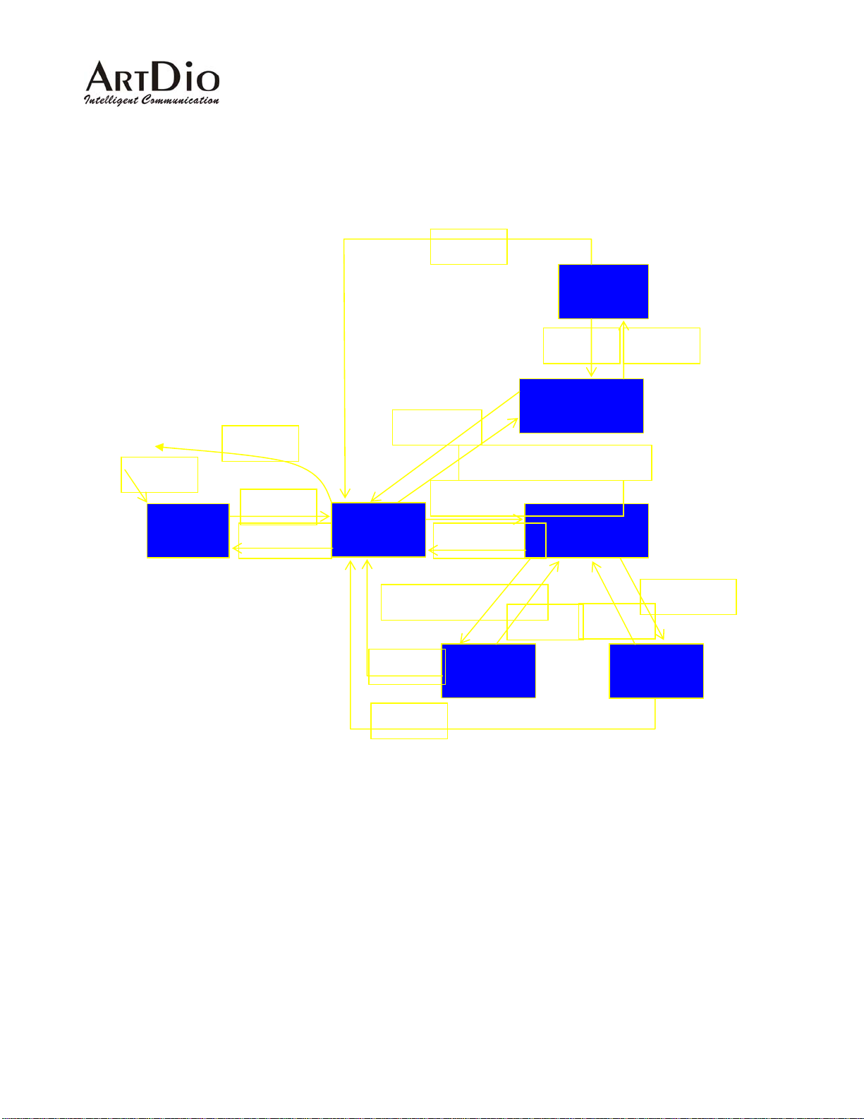
4. Basic Configuration
4.1 System Console Modes
end
login
EXEC
exit
enable
disable
Privileged
line console
end
exit/end
configure
exit/end
Console
Routing
exit
Code
code exit
Routing
Configuration
channel
exit
Channel
4.2 System Management
The following general information is needed to configure the system with the appro priate routing information
to route calls between PBXs and voice gateways. You must configure the prefix and group ID that will be
used inside the group of PBX VoIP gateways. The master gateway IP address is essential for a PBX V oIP
gateway to synchronize the routing information.
end
35
Page 36
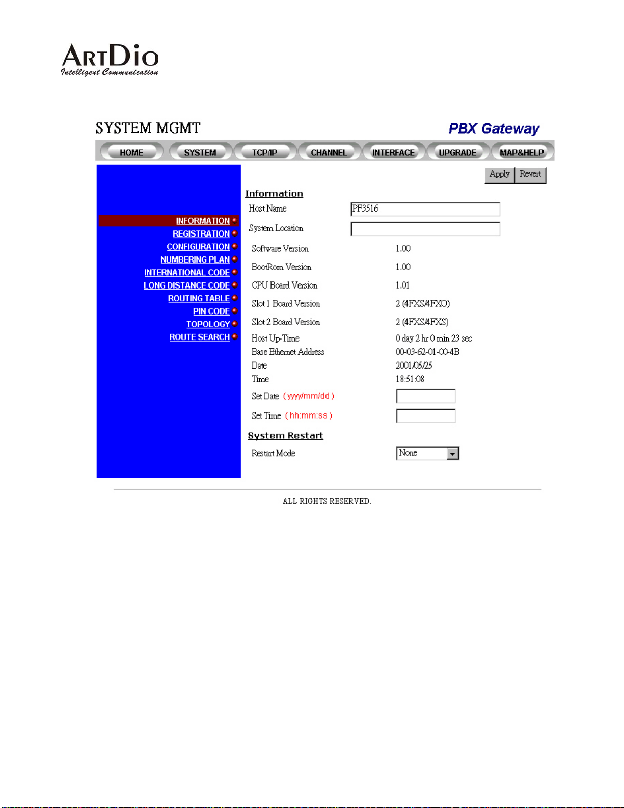
4.2.1 Information-Web Management
36
Page 37
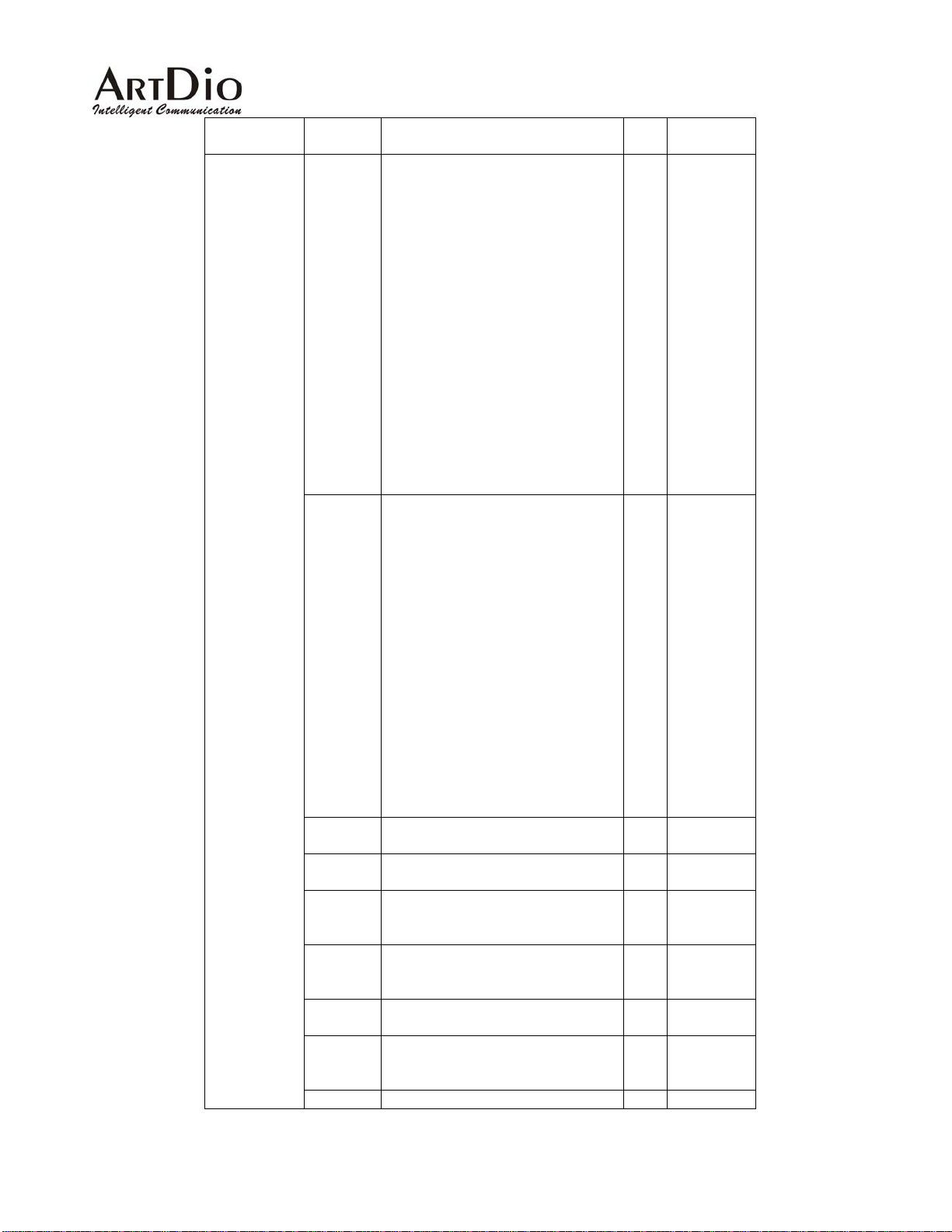
Category Entry Description Data
Range
Type
Information
Host
Name
Name of the gateway for the
system administrator to distinguish
this gateway from others. It will
also be used as a prompt in the
system console.
RW Any string
up to 48
characters
in length
can be
used. You
may input a
total of 255
characters.
However,
once a
length of 48
is reached,
any
characters
above that
will be
truncated.
Location This entry allows the system
administrator to identify the
gateway’s location.
RW Any string
up to 48
characters
in length
can be
used. You
may input a
total of 255
characters.
However,
once a
length of 48
is reached,
any
characters
above that
will be
truncated.
Software
Current software version RO X.XX
Version
BootRom
Current BootRom Code version RO X.XX
Version
CPU
Current CPU Board version RO X.XX
Board
Version
FXS
Current FXS Board version RO X.XX
Board
Version
Host UpTime
Base
Ethernet
System Up-Time since the last
Warm Start
The Ethernet Address of this
device
RO X.XX
RO XX-XX-XX-
XX-XX-XX
Address
Date Current date RW yyyy/mm/dd
37
Page 38
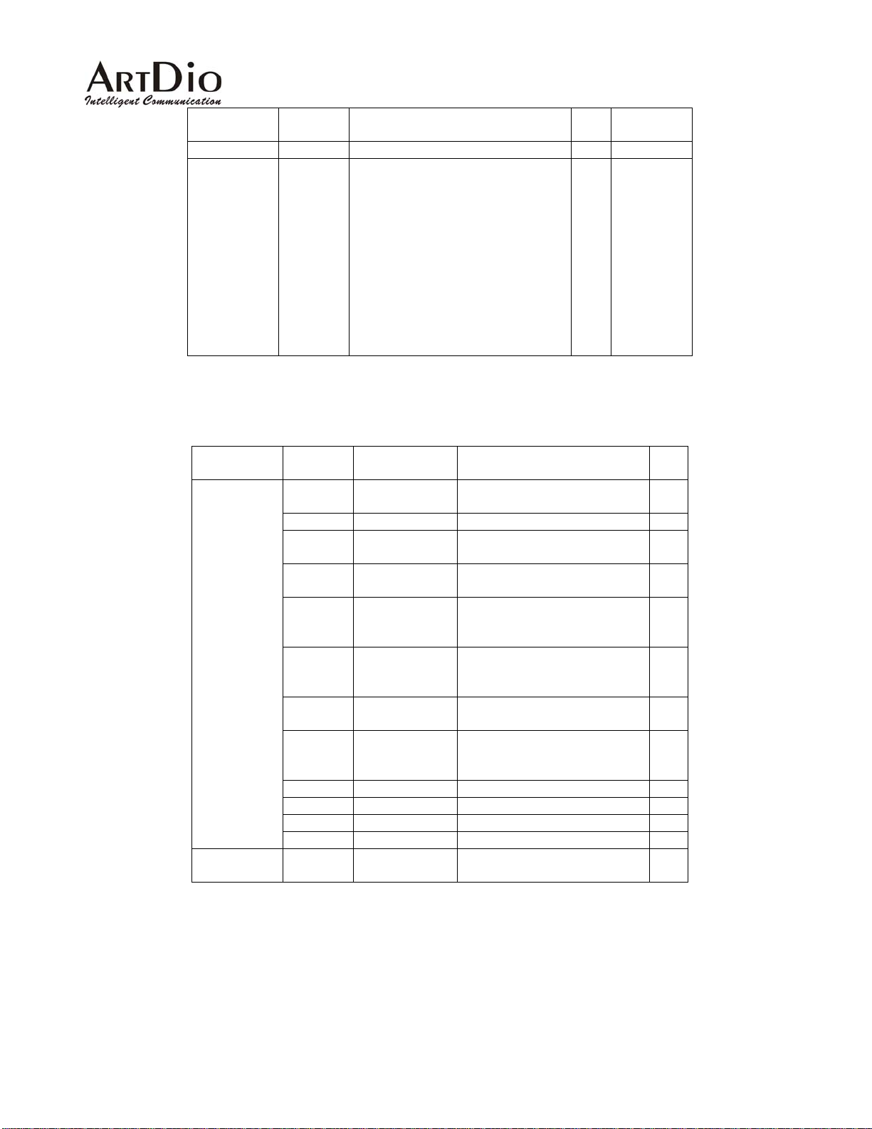
Category Entry Description Data
Time Current Time RW hh:mm:ss
System
Restart
Restart
Mode
This pull-down menu allows you to
select the restart mode:
None: No system restart will be
issued:
Cold Start: The system will restart
from the beginning. The running
code will be decompressed from
the flash memory and initiate all
the system parameters.
Warm Start: The system will
restart but the running code will not
be decompressed.
4.2.2 Console Commands -System Information
Category Entry Console Mode Console Command Data
Information
System
Restart
Host
Name
Location Configuration
Software
Version
BootRom
Version
CPU
Board
Version
FXS
Board
Version
Host UpTime
Base
Ethernet
Address
Date EXEC/Privilege
Time EXEC/Privilege
Date Configuration
Time Configuration
Restart
Mode
Configuration
EXEC/Privilege
EXEC/Privilege
EXEC/Privilege
EXEC/Privilege
EXEC/Privilege
EXEC/Privilege
Privilege
hostname <string>
location <string>
Show Version
Show Version
Show Version
Show Version
Show Version
Show Version
Show date
Show time
date <yyyy/mm/dd>
time <hh:mm:ss>
restart for warm start
reload for cold start
Range
Type
RW NONE
Cold Start
Warm Start
Type
RW
RW
RO
RO
RO
RO
RO
RO
RO
RO
RW
RW
WO
38
Page 39
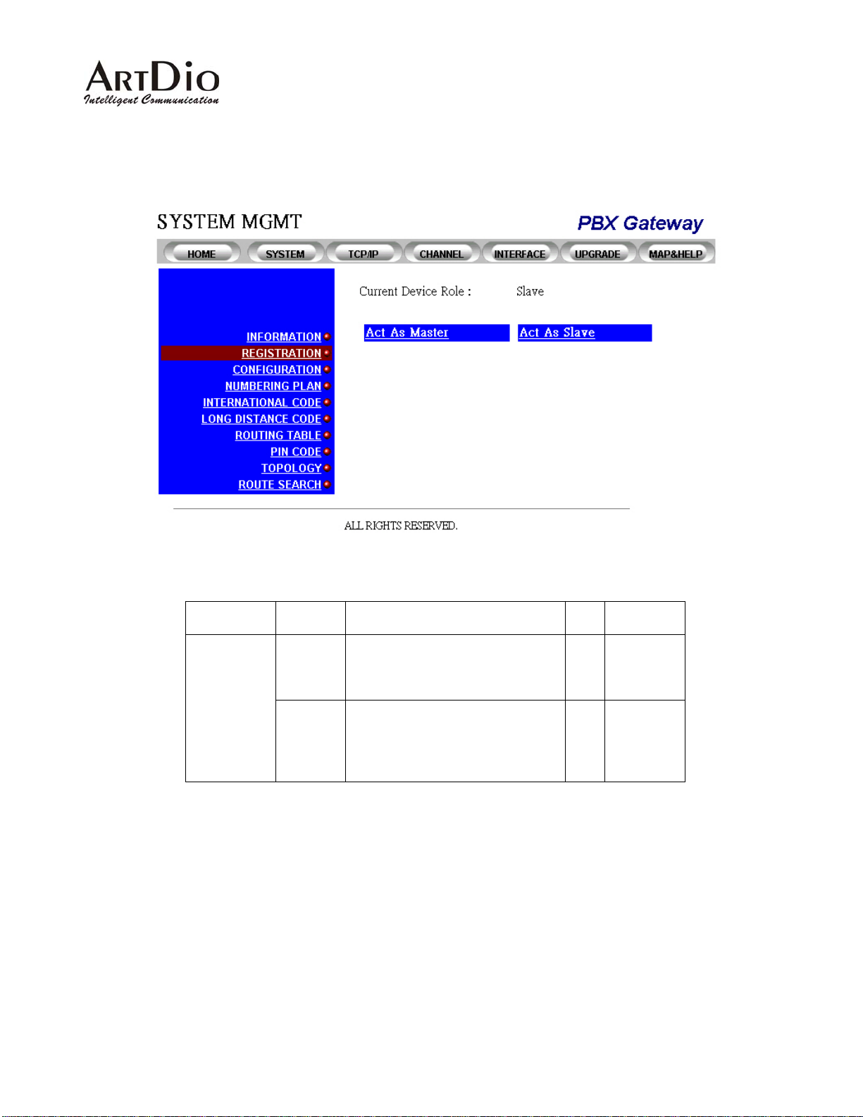
4.2.3 Registration-Web Interface
Category Entry Description Data
Registration
Current
Device
Role
As Master
/
As Slave
Slave: This device is currently
configured as a slave gateway.
Master: This device is currently
configured as a master gateway.
Name of the gateway for the
system administrator to distinguish
this gateway from others. It will
also be used as a prompt in the
system console.
Range
Type
RO
RO
39
Page 40
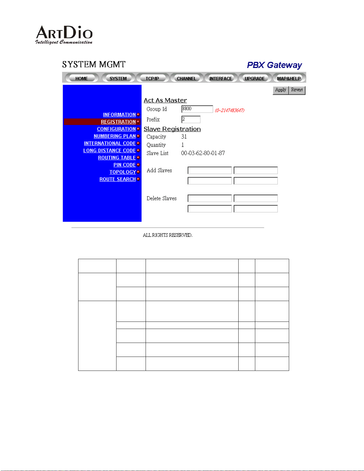
As a Master
Category Entry Description Data
Act As
Master
Group ID The Group ID for PBX VoIP
Gateway
Prefix The prefix is the code used to route
a call to this gateway
Slave
Registration
Capacity The allowed capacity for slave
entries
Quantity Current registered slaves RO 0~31
Slave List The list of MAC addresses of
slaves currently registered.
Add
Slaves
Delete
Salves
Entry to add the MAC address of a
slave
Entry to delete the MAC address of
a slave
Range
Type
RW 0~2147483
647
RW 1~9999
RO 31 not
including
the Master
RO
RW XX-XX-XX-
XX-XX-XX
RW XX-XX-XX-
XX-XX-XX
40
Page 41
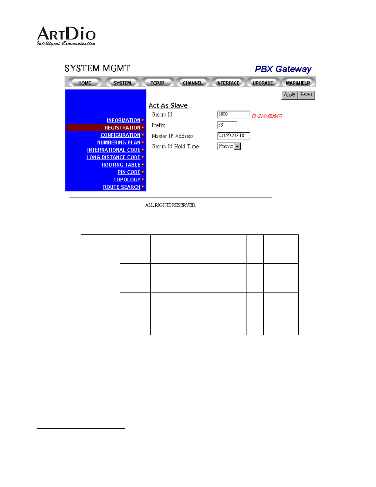
As a Slave
Category Entry Description Data
Range
Type
Act As Slave
Group ID The Group ID for the PBX VoIP
Gateway
Prefix The code used to route a call to
RW 0~2147483
647
RW 1~9999
this gateway
Master IP
Address
Group ID
Hold
Time
The IP Address of the Master
gateway
The Hold Time for the Group ID in
the device when it is switched off
4
RW XXX.XXX.X
XX.XXX
RW Forever|0.5
hr|1.0 hr|1.5
hr|2.0 hr|2.5
hr|3.0 hr|3.5
hr|4.0 hr|4.5
hr|5.0 hr
4
The Group ID Hold time is used to protect the group ID, as well as to deter any would be intruders from stealing the device and re-installing it
at another location.
41
Page 42
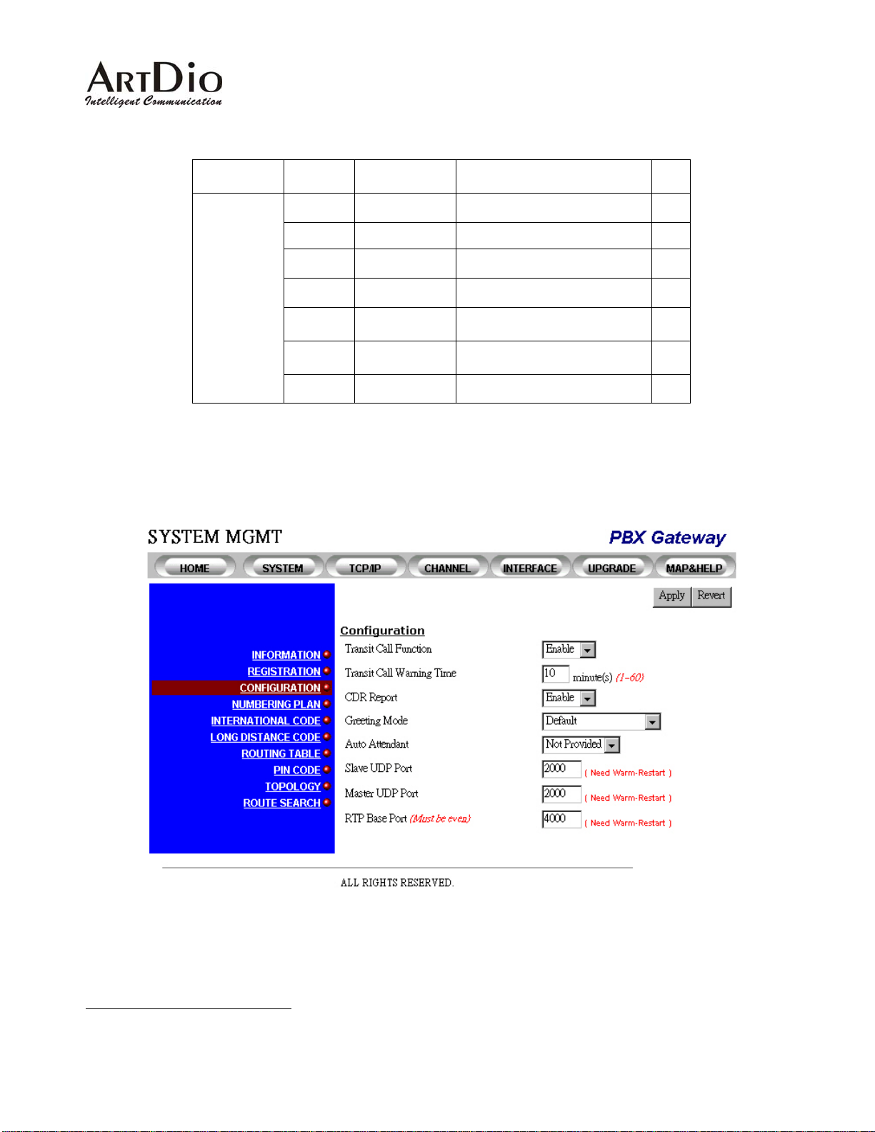
4.2.4 Registration Information- Console Interface
Category Entry Console Mode Console Command Data
Registration
Group ID Routing
group_id <number>
Type
RW
Prefix Routing
Master IP Routing
Add Slave Routing
Delete
Routing
Slave
Group ID
Routing
Hold Time
Slave List Routing
4.2.5 Configuration-Web Interface
prefix <number>
master_ip
<xxx.xxx.xxx.xxx>
Slave add
<ffffff-ffffff>
Slave del
<ffffff-ffffff>
gid_tmr <0-255>
show slave
5
RW
RW
RW
RW
RW
RO
5
The “show slave” option is only available using the console interface on the master gateway. .
42
Page 43
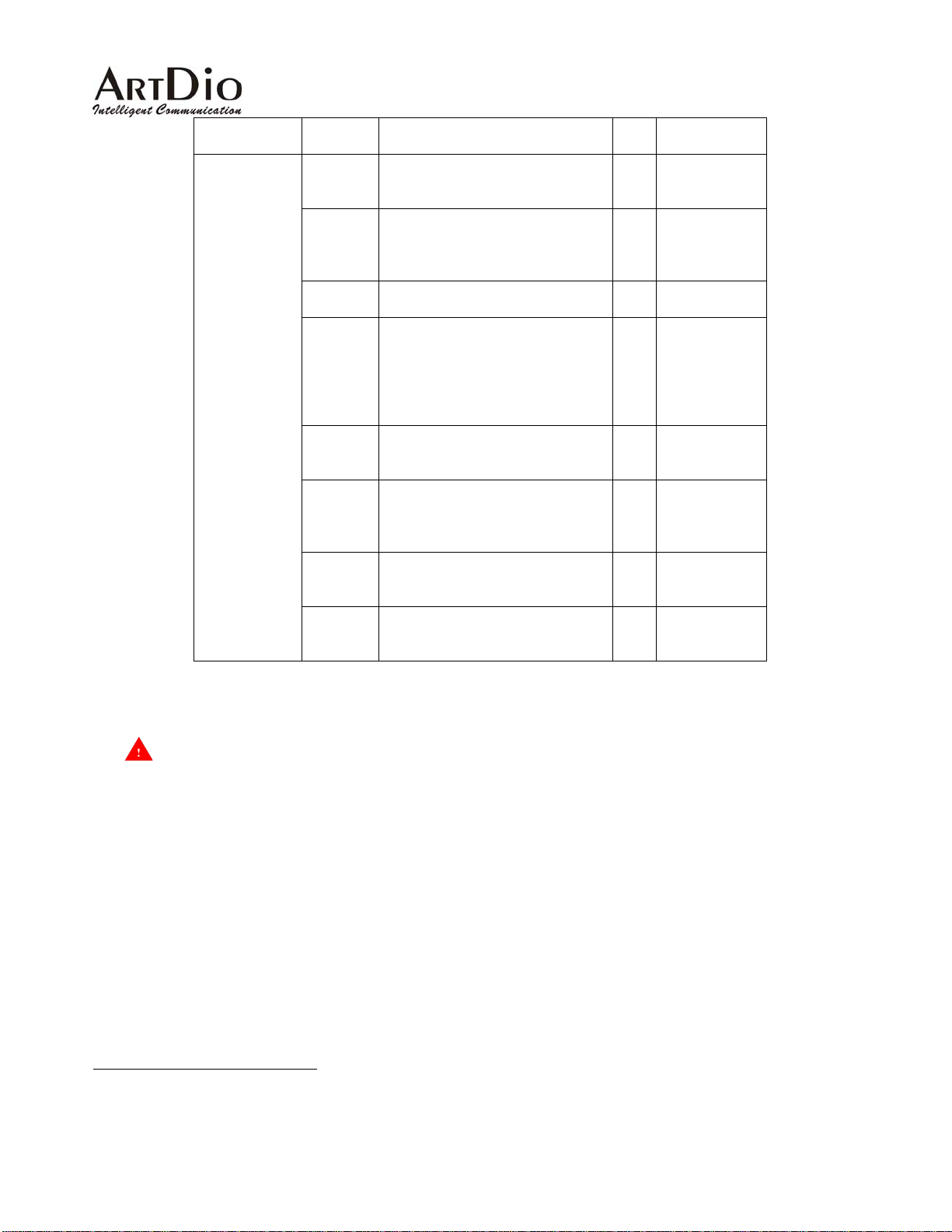
Category Entry Description Data
Range
Type
Configuration
Transit
Enable or disable Transit Calls RW Enable/Disable
Call
Function
Transit
Call
Waiting
The timer for sending a warning
tone to the caller while a transit
call is taking place.
RW (1~60) min
(Default=3)
Time
CDR
Report
Greeting
Mode
Auto
Attendant
Enables or disables CDR report
6
output
There is no message recorded by
default.
Y ou can record your own greeting
message and select how many
times to play the recording.
7
Shows whether or not your PBX
is equipped with the Auto
RW Enable/Disable
RW Default(Not to
play), Play
Recording
Once, twice, 3,
4, 5, 6, 7, 8
times
RW Provided/Not
Provided
Attendant function
Slave
UDP Port
No.
The UDP port number which
carries Call Control signaling
from this slave devices with other
RW 0~65535
(default value
is 2000)
gateways
Master
UDP Port
No.
RTP Base
Port No.
The UDP port number which
carries Port Information signals to
the master device
The Base RTP port number which
carries voice streaming data
RW 0~65535
(default value
is 2000)
RW 0~65535
(must be even)
between gateways
Note 2 The master UDP port number on slave devices should be the same as the definition on the master
device. But the slave UDP port number for each slave may be different for each device.
The configurations of the UDP port number and the RT P port number are relate d to the firewall settings of
your network (refer to chapter 6 Firewall Configuration). Please consult your netwo rk a dministrator before
making any changes.
6
CDR report works only on models that are equipped with the extra RS-232 CDR output interface
7
You can use the Phone Set Interface to configure the Skip Greeting Access Code (item code 30) to specify the access code while trying to
bypass the greeting message recorded in the device.
43
Page 44
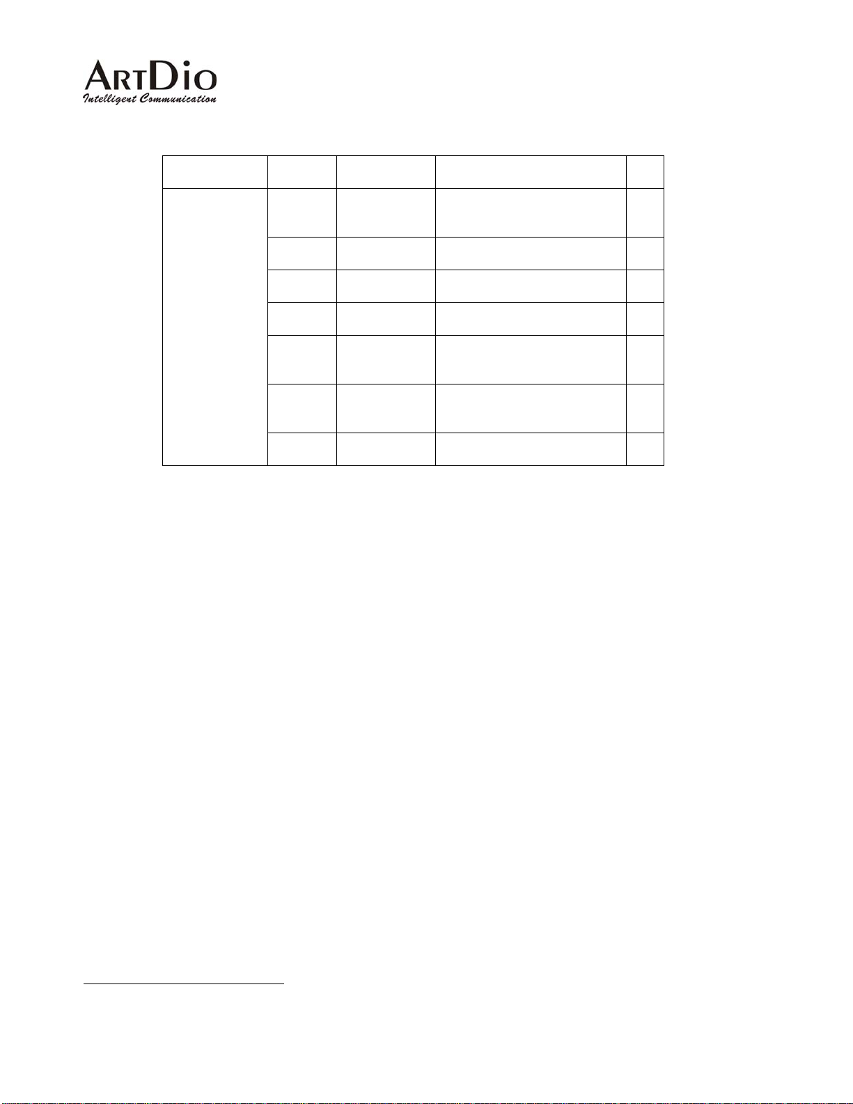
4.2.6 Configuration Information- Console Interface
Category Entry Console Mode Console Command Data
Routing
Transit
Routing
Call
Function
CDR
Routing
Report
Greeting
Routing
Mode
Auto
Routing
Attendant
Master
Routing
UDP Port
No.
Slave
Routing
UDP Port
No.
RTP Base
Routing
Port No.
transit_call
<enable/disable>
8
cdr
<enable/disable>
greet_mode
<default/recoding>
auto_attn
<enable/disable>
udp_port master
<0-65535>
udp_port slave
<0-65535>
rtp_base <0-65535>
Type
RW
RW
RW
RW
RW
RW
RW
8
The CDR function is not provided in FXS only models.
44
Page 45
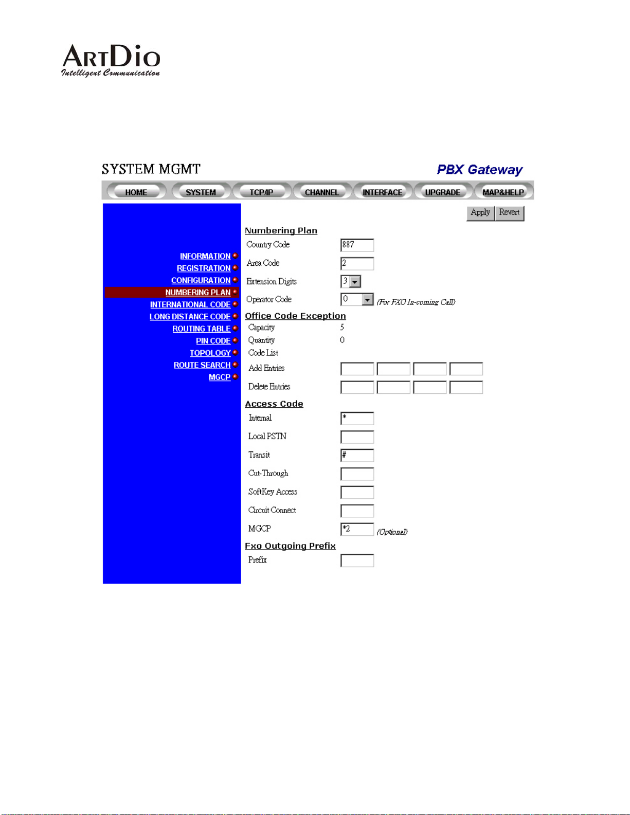
4.2.7 Numbering Plan-Web Interface
45
Page 46
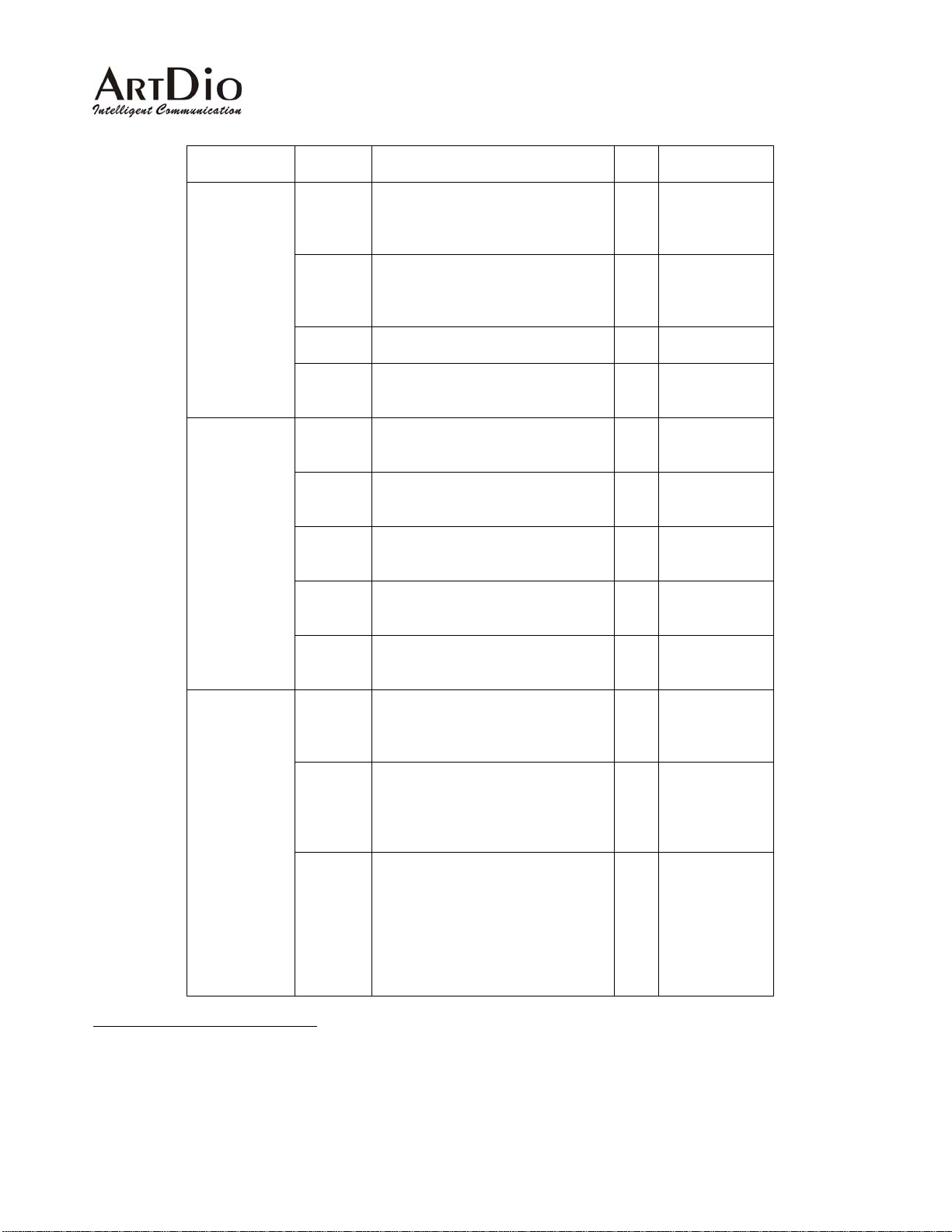
Category Entry Description Data
Type
Numbering
Plan
Country
Code
The Country Code where this
gateway is located. Used for
RW 1~999
receiving incoming calls from other
countries
Area
Code
The Area Code where this
gateway is located. Used for
RW 1~999
receiving incoming calls from other
areas
Extension
Digits
Operator
Code
The number of digits for the PBX
lines
The number that the PBX assigns
9
that is used to connect to the
RW 1-9
RW NONE, 0-9
operator
Office Code
Exception
10
Capacity The number of Exceptional Office
Code entries that are allowed to be
RO 5
specified on this gateway
Quantity The number of Exceptional Office
RO 0-5
Code entries that are currently
specified on this gateway
Code List The list of Exceptional Office
RO [0~9],
Codes that are currently
configured in this gateway
Access Code
Add
Entries
Delete
Entries
Internal The Access Code used to make a
The Exceptional Office Codes to
be added to the Code List
The Exceptional Office Codes to
be removed from the Code List
WO [0~9],
WO [0~9],
RW [0~9,*,#][0~9],
call in-between the PBX gateways
in the same group (See application
in 2.1 Internal Calls)
Local
PSTN
Define the Ac cess Code to force a
call in from local FXS and out from
local FXO interface on the PBX
gateway to PSTN
11
. (FXS to
RW [0~9,*,#][0~9],
FXO ;bypass of routing selection)
Transit The Access Code used to make a
RW [0~9,*,#][0~9],
call from the PSTN to the FXO port
on this device and call out from the
FXO interface on the remote PBX
gateway to the PSTN (This
function takes effect only when you
have FXO interfaces existing in
your group)
12
Range
example
"0349", "0343"
example
"0349", "0343"
example
"0349", "0343"
example
"*12345"
(Default=*)
example
"*12345"
example
"*12345"
(Default=#)
9
If you assign “0” as the operator access code, please ensure that “0” is not also the long distance access code. If both the operator access
code and the long distance access codes are assigned “0”, the PBX gateway will treat the number as a call to operator of your PBX.
10
Office Code Exception are the Area Codes of other locations that have first few digits are exactly the same as the Area Code for this PBX
Gateway, it should take as a long distance call if we wants to make a calls to those area.
11
This function works only on models that come with the FXO interface.
12
This function works only on models that come with the FXO interface.
46
Page 47

Category Entry Description Data
Range
Type
Cut
Through
While access the FXO ports, in
order to dial out directly bypass to
the FXS ports of this device without
listen to the Greeting Message that
recorded in the device, then press
RW [0~9,*,#][0~9],
example
"*12345"
(Default is
Blank)
this Access Code. (FXO to FXS)
Softkey
Access
Define the Acce ss Code to trigger
the soft-key defined for each
channel manually
RW [0~9,*,#][0~9],
example
"*12345"
(Default is
empty)
Circuit
Connect
Define the Ac cess Code for logical
circuit-connect dialing. With this
access code plus the prefix and
port number, the port that start this
circuit connect action will
RW [0~9,*,#][0~9],
example
"*12345"
(Default is
empty)
connected to the remote port
similar that there are circuit
between.
MGCP Define the Acce ss Co de to make a
call to remote MGCP registered
entries. Example: *2 is the MGCP
access code, 30002300 is the
number of entry that registered in
RW [0~9,*,#][0~9],
example
"*12345"
(Default is
empty)
Call Agent. Dial "*2" first, after
hearing the dial tone, dial
"30002300" user can hear the ring
back tone that connecting to this
entry.
FXO
Outgoing
Prefix
Prefix Define the prefix that whenever
dial out from FXO port, it is useful
for connecting under the lines of
PBX
RW [0~9,*,#][0~9][P
13
], example
"9P"
(Default is
empty)
13
"P" in large capital means pause for one second, while connecting the voice gateway to extension lines of PBX, it will take seconds for PBX
to find an available PSTN connection for you. User can apply multiple "P" if user wants take pause for more than one second.
47
Page 48
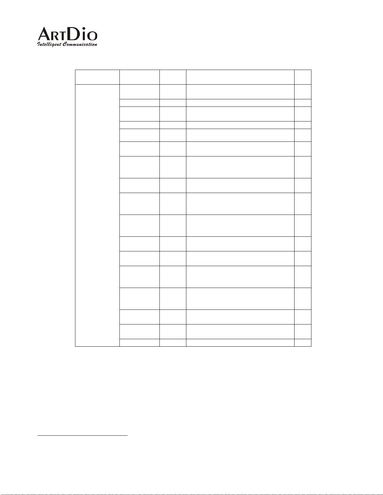
4.2.8 Numbering Plan Information- Console Interface
Category Entry Console
Mode
Routing
Configuration
Country
Code
Area Code Code
Circuit
Code
Code
Connect
Cut_Through Code
Dial Code Code
Extension
Code
Digits
FXO
Code
Outgoing
Prefix
Internal
Code
Access Code
International
Code
Call Access
Code
Long
Code
Distance Call
Access Code
Local PSTN
Code
Access Code
Office Code
Code
Exception
PBX
Code
Operator
Access Code
Phone Set
Code
Program
Access Code
Softkey
Code
Access
Transit Call
Code
Access Code
MGCP Call Code
Console Command Data
country <1-999>
area <1-999>
circuit_connect <Access Code>
Cut_Through <Access Code>
Dial_code <international|
long_distance> <1-999>
extension_len <1-9>
fxo prefix <Access Code|P
internal_ac <Access Code>
intn_code <1-999>
long_distance <1-999>
local_pstn_ac <Access Code>
office_excp <1-999>
oper_code <d|1~9>
(d is the default value, that
stands for None Operator Code)
prog_ac <Access Code>
(Default=##)
soft_start <Access Code>
transit_ac <Access Code>
voiptk_ac
Type
RW
RW
RW
RW
RW
RW
14
>
RW
RW
RW
RW
RW
RW
RW
RW
RW
RW
RW
Note 3 An access Code can be character s ranging from [*|#|0~9] or the character plus a number
between 1 and 5 digits. For example, you can set your access code to "*", "*1", "*999" ,etc...
14
After the FXO outgoing prefix code, you can add “P” which means pause for one second. If multiple “P” are specified, the number of “P” will
be the number of seconds before sending the reset of digits.
48
Page 49
A
4.2.9 International Code-Web Interface
Category Entry Description Data
International
Access Code
(Outbound)
International
Access Code
(Inbound)
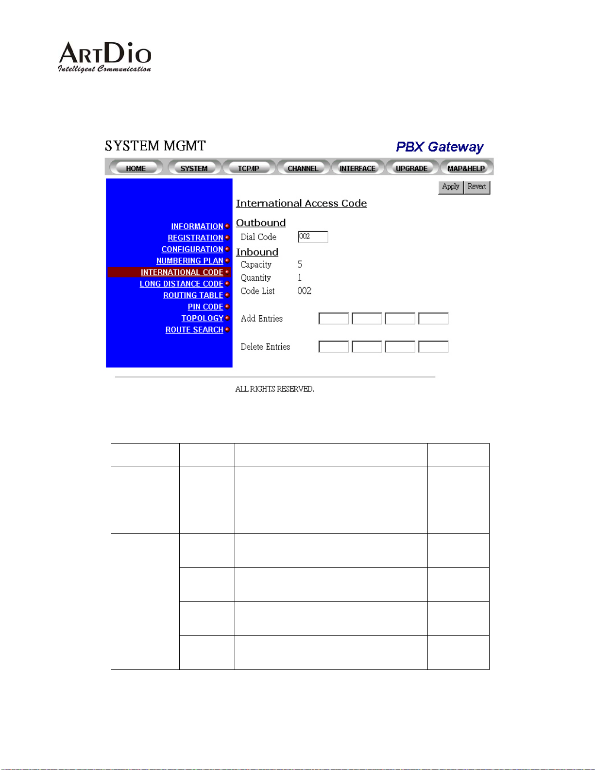
Dial Code The number that is added before the
Country code, Area Code and
subscriber's telephone number to gain
International Call access.
Applies to PBX Gateway with FXO
interface only.
Capacity The number of In-bound International
Access Code entries that are allowed
to be specified on this gateway
Quantity The number of In-bound International
ccess Code entries that are currently
specified on this gateway
Code List The list of Inbound International
Access Codes that are currently
configured on this gateway
Add Entries The Access Codes that you are going
to add to the Code List
Range
Type
RW 0-999
RO 5
RO 0-5
RO [0~9],
example
"012", "002"
WO [0~9],
example
"012", "002"
49
Page 50

Note 4 The Inbound International Access Code is used to analyze the number that the gateway is
receiving from analog voice interfaces. The received numbers are carried with this specified
Inbound International Access Code, a nd the call will be routed to the remote gate way through
the FXO interface to its PSTN. The user will then only need to pay domestic phone fees
instead of international phone fees. Or, an international call will be sent directly through the
local FXO interface as an international call from a local PSTN and will not be able to benefit
Delete
Entries
The Access Codes that you are goin g
to remove from the Code List
WO [0~9],
example
"012", "002"
from the Toll-bypass advantage.
through the remote gateway, leave the In-bound International Access Code entry blank.
If your gateway is not permitted to make international calls
4.2.10 International Code Information- Console Interface
Category Entry Console Mode Console Command Data
International
Access
Code
(Outbound)
International
Access
Code
(Inbound)
Dial Code Code
Code List Code
Add
Entries
Delete
Entries
Code
Code
dial_code
international <1-999>
show ac_summary
intn_code add <1-999>
intn_code del <1-999>
Type
RW
RO
RW
RW
Note 5 The Access Code here is the same as the code that you would be dialing locally to make an
international call.
50
Page 51
4.2.11 Long Distance Code-Web Interface
Category Entry Description Data
Type
Long
Distance
Access Code
(Outbound)
Long
Distance
Access Code
(Inbound)
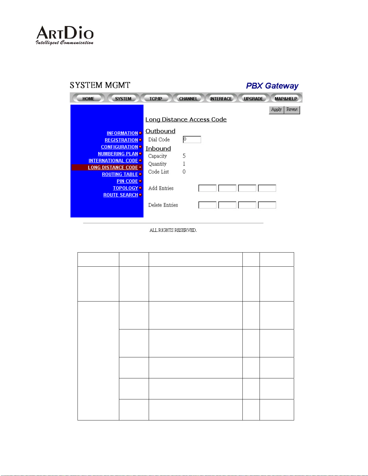
Dial Code The number plus the Area Code
and the subscriber's telephone
number.
Applies to PBX Gateway with FXO
interface only.
Capacity The number of In-bound
International Access Code entries
that are allowed to be specified on
this gateway
Quantity The number of In-bound
International Access Code entries
that are currently specified on this
gateway
Code List The list of Inbound International
Access Codes that are currently
configured on this gateway
Add
Entries
Delete
Entries
The Access Codes that you are
going to add to the Code List
The Access Codes that you are
going to remove from the Code List
RW 0-999
RO 5
RO 0-5
RO [0~9],
WO [0~9],
WO [0~9],
Range
example
"012", "002"
example
"012", "002"
example
"012", "002"
51
Page 52

4.2.12 Long Distance Code Information- Console Interface
Category Entry Console Mode Console Command Data
Long
Distance
Access
Code
(Outbound)
Long
Distance
Access
Code
(Inbound)
Note 6 The Access Code here is the same as the code that you would be dialing locally to make a
Long Distance call.
Dial Code Code
Code List Code
Add
Entries
Delete
Entries
Code
Code
dial_code
long_distance <1-999>
show ac_summary
long_distance add
<1-999>
long_distance del
<1-999>
Type
RW
RO
RW
RW
52
Page 53
4.2.13 Routing Table-Web Interface
Category Entry Description Data
Range
Type
Routing Table
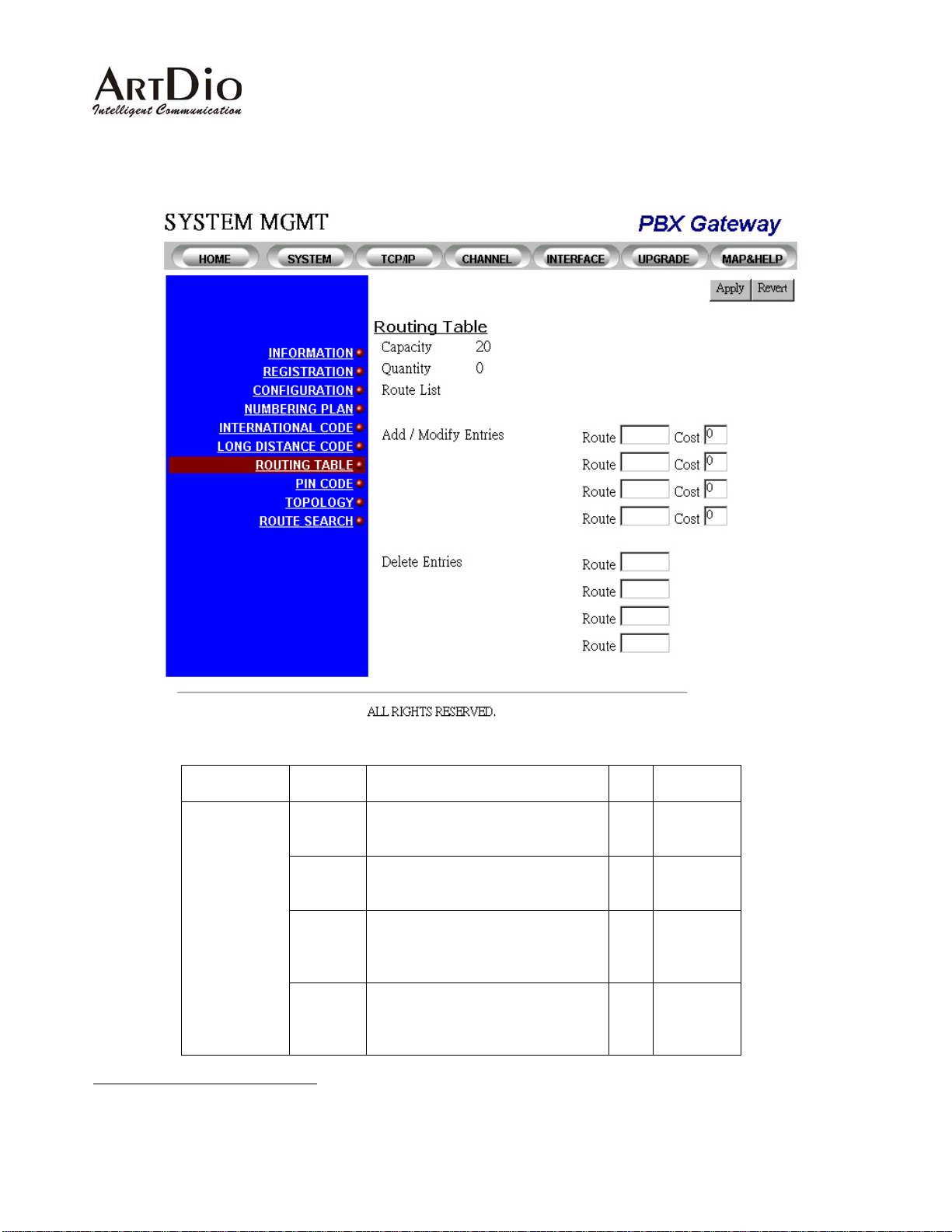
Capacity The number of allowed entries
used for routing a call to the PSTN
via the gateway
15
Quantity The number of routing entries that
RO 20
RO 0-20
are currently configured on the
gateway
Route List List of route entries with their
corresponding route costs
RO Format:
[Routing
Entry Cost]
Add
/Modify
Entries
To add or modify a routing entry
and/or its cost
WO
Routing
Entry:
0-999999;
Cost: 1~99
15
This function works only on gateways that are equipped with the FXO interface. For FXS only gateways, you will not be able to see the
members list under the Topology icon using the Web Interface.
53
Page 54

Note 7 For example, if a gateway is installed in th e USA and is assigned to be the routing gateway for
all calls in the group to Ottawa, Canada, the routing entry for this example will be 1613 with
cost 1 . You will also need to specify the outbound International Access Code 011. So calls
from a gateway in Hong Kong will be routed to a PSTN in the USA using the dial out number
011-1-613-xxxx-xxx to Ottawa-Canada.
Delete
Entries
To delete a routing entry WO 0-999999
4.2.14 Routing Table- Console Interface
Category Entry Console Mode Console Command Data
Type
Routing
Table
Route List Routing
Add
/Modify
Entries
Delete
Entries
Routing
Routing
show call_route
call_route add
<0-999999> <1-99>
call_route del
<0-999999>
RO
WO
WO
Note 8 To modify a routing entry in the Console Interface, you must delete that entry and replace it
with the new value that you want to modify.
54
Page 55
4.2.15 Pin Code Assignment-Web Interface
Category Entry Description Data
PIN Code For
Transit Call
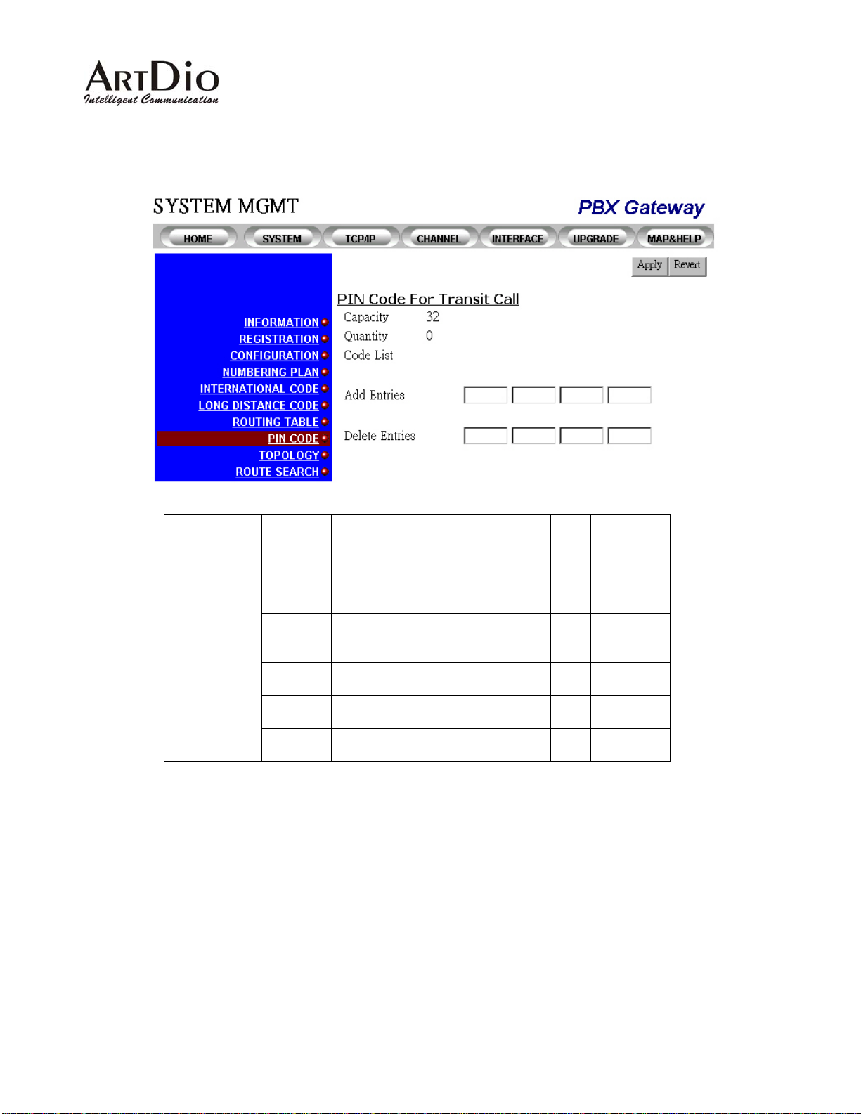
Capacity The allowed amount of entries for
PIN codes that are used when
making transit calls via the
gateway
Quantity The number of PIN codes that are
currently configured on this
gateway
Code List The list of PIN codes that are
configured on this gateway
Add
Entries
Delete
Entries
To add a PIN Code entry WO
To delete a PIN Code entry WO
Range
Type
RO 32
RO 0-32
RO
0-99999999
0-99999999
The PIN Codes are needed to make calls that dial from a PSTN, which then go through an IP network to a
remote PBX gateway and then to the PSTN where the remote gateway is located.
55
Page 56
4.2.16 Pin Code Assignment- Console Interface
Category Entry Console
Mode
Routing
Configuration
Code List Routing
Add Entries Routing
Delete
Entries
Routing
Console Command Data
show pin
pin add <0-99999999> <1-99>
pin del <0-99999999>
Type
RO
WO
WO
56
Page 57
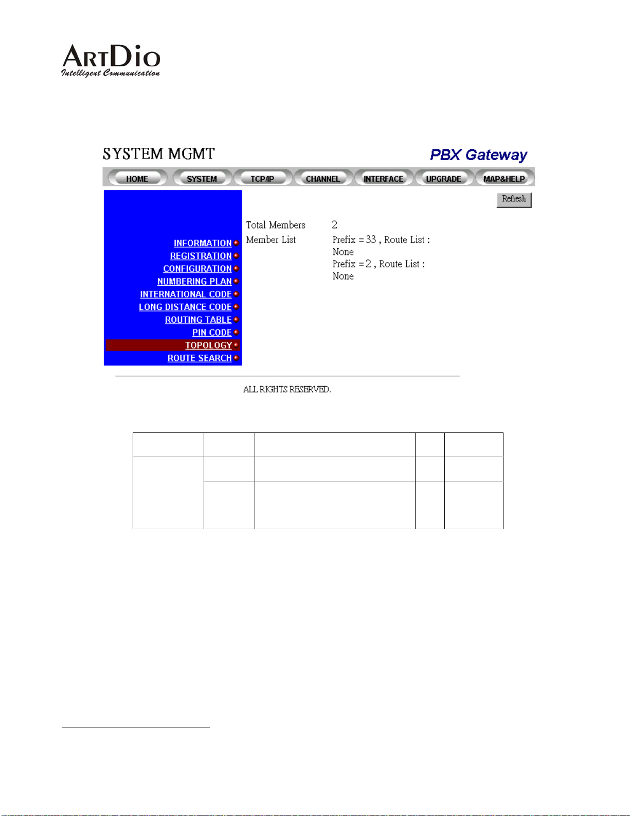
4.2.17 Topology-Web Interface
Category Entry Description Data
Topology
Total
Members
Member
List
The number of members in the
same group
The list of gateways in the same
group. Displays the corresponding
prefix that is specified for each
gateway
16
4.2.18 Topology- Console Interface
Note 9 There is no similar function in the Console Interface
Range
Type
RO
RO
16
For models that are equipped with the FXO interface, the route list with the prefix will be displayed in the Member List.
57
Page 58
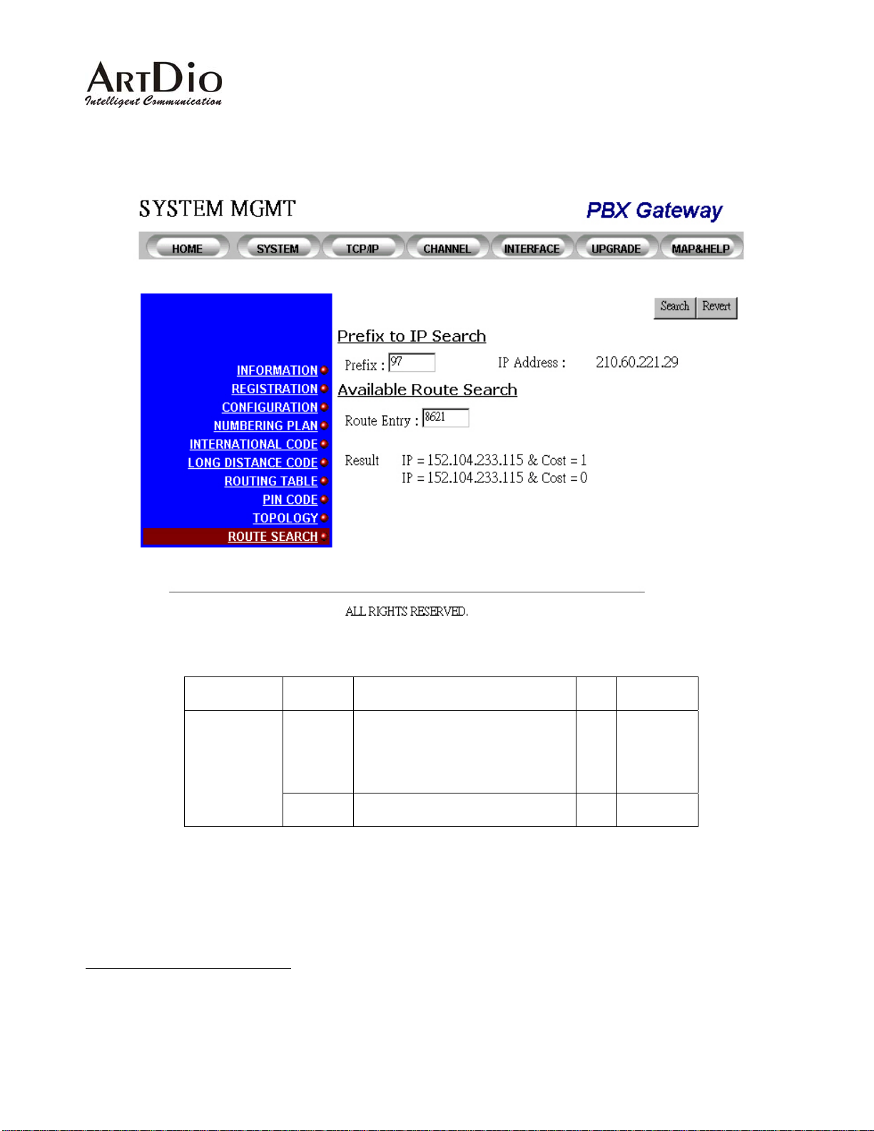
4.2.19 Route Search-Web Interface
Category Entry Description Data
Range
Type
Route Search
IP
Address
If the Prefix that is specified in the
previous section cannot be found,
RO
the IP address of that gateway will
be displayed. Otherwise, "Not
Found" will be displayed.
Route
Entry
The Route Entry that will be
searched
17
WO
4.2.20 Route Search- Console Interface
Note 10 There is no similar function in the Console Interface
17
This function has the same restrictions as other routing table related functions. For example, you want to find an entry that is specified on a
gateway without the FXO interface. However, the gateway is unable to route your calls to the PSTN through the FXO,so you will not get the
desired search results even if you have specified the routing entry correctly. The search entry does not allow wild cards, so you must enter the
search criteria exactly the same as what you specified in the routing entries.
58
Page 59
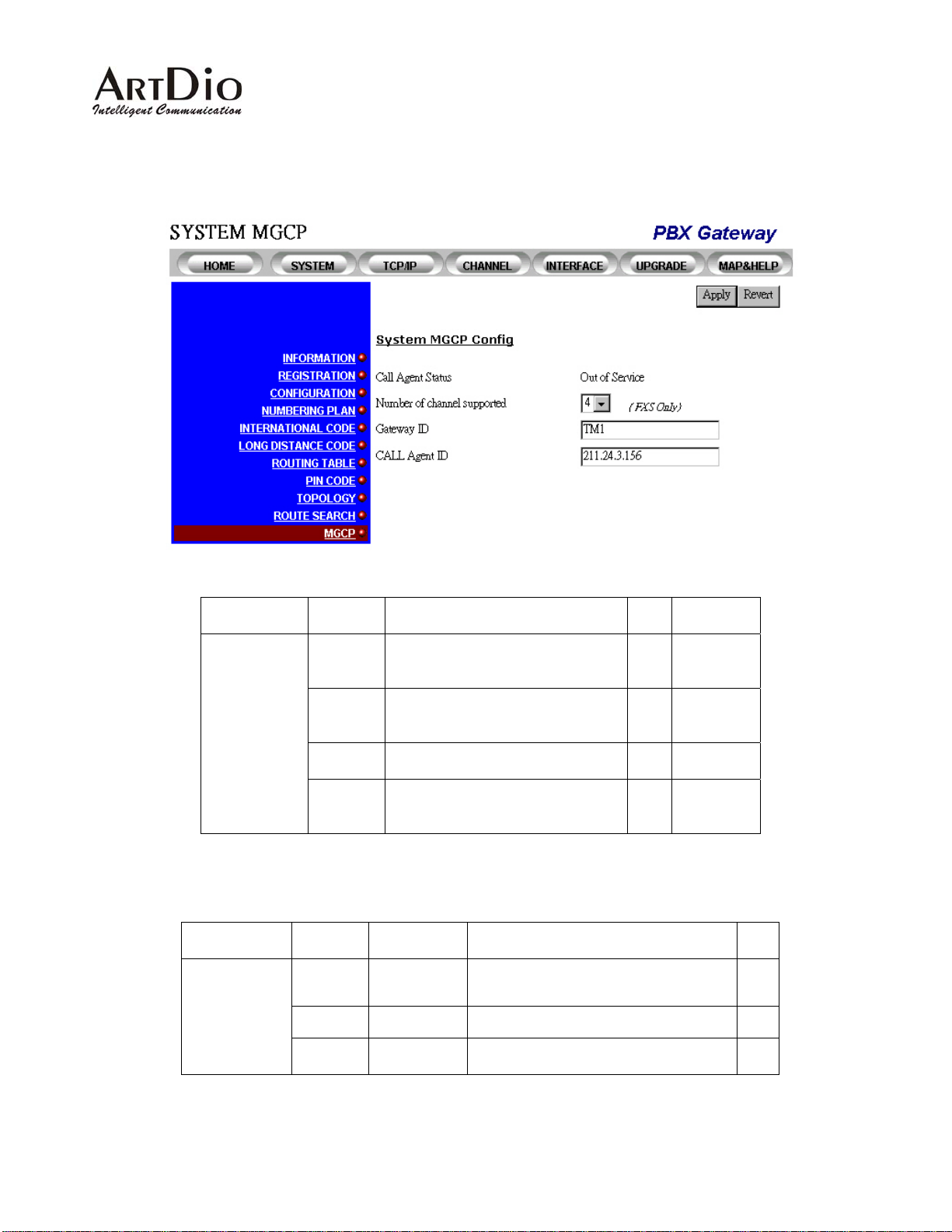
4.2.21 MGCP Configuration - Web Interface
Category Entry Description Data
System
MGCP Config
Call Agent
Status
Number of
channel
supported
Gateway
ID
Call Agent
ID
The status whether this voice
gateway connect to call agent or
not
The number of channels that
registered with call agent
The name of this gateway that
register on call agent
The IP address or domain name of
call agent, used for this gateway to
connect with call agent
4.2.22 MGCP Configuration - Console Interface
Category Entry Console
Mode
MGCP
Configuration
gwid Configuration
call-agent Configuration
mgcp_chan Configuration
Console Command Data
gwid <string of name for this
gateway registered in Call
Agent>
call-agent <string of name for
call agent or its IP address>
mgcp_chan [0|4|8]
Range
Type
RO Out of
Service, In
Service
RW 0, 4, 8
RW String
RW
String or IP
address
Type
WO
WO
WO
59
Page 60
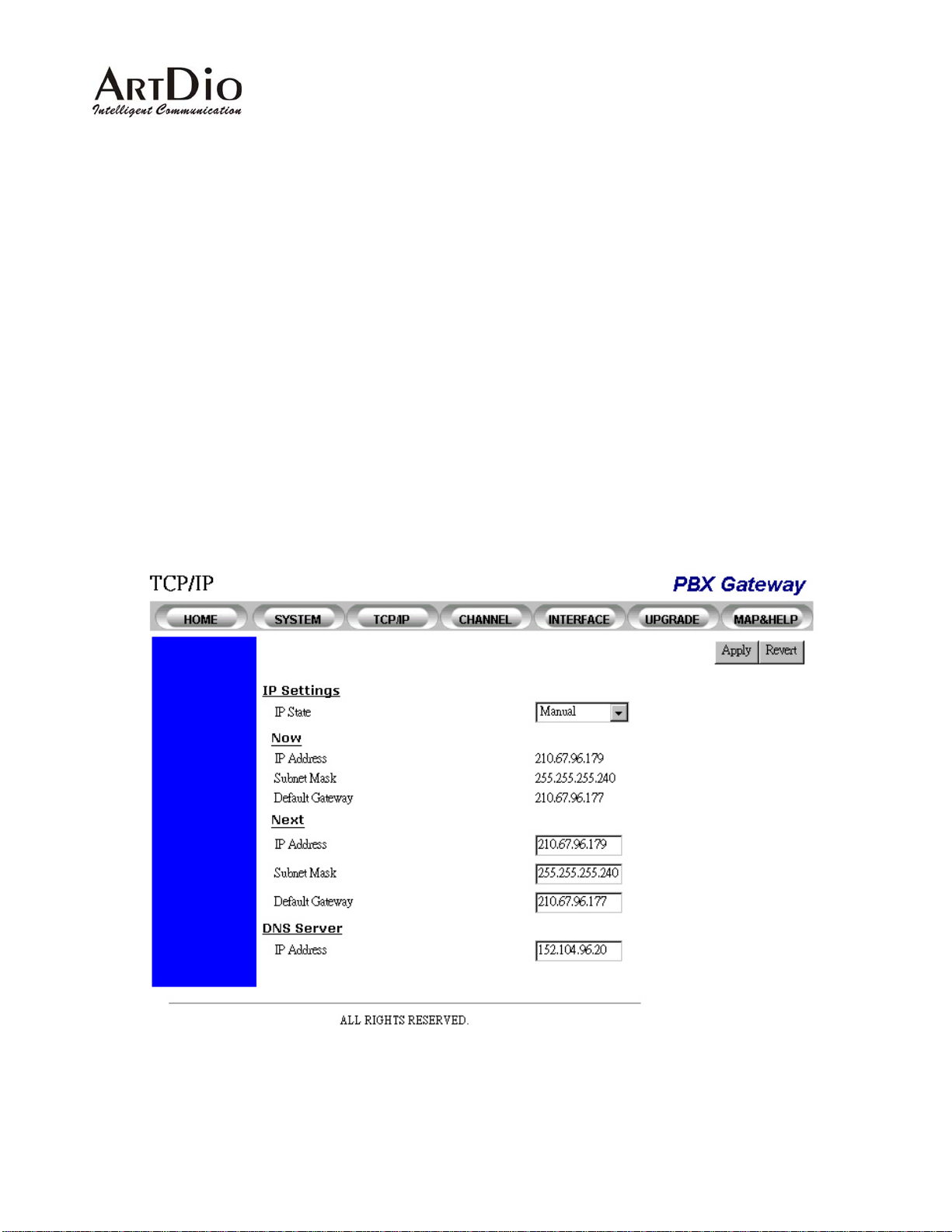
4.3 TCP/IP Configuration
The TCP/IP can be configured through the system console and the W eb manag ement interface. The re are
two ways to obtain the IP address:
1. Manually assigned.
2. DHCP server assigned.
Y ou can select which way you prefer to obt ain the IP b y setting the IP S t ate mode. If Manual is selected, t he
administrator must assign it manually. If DHCP is selected, it will obtain the IP from the DHCP server. You
need to set up a DHCP server and configure its IP address so that the gateway is able to locate it. If the
gateway is configured using the DHCP mode but cannot find the DHCP server, it will use the IP that was
previously configured. After the gateway has successfully acquired the IP address, it will update the newly
acquired (manually configured) IP.
Web Management
60
Page 61
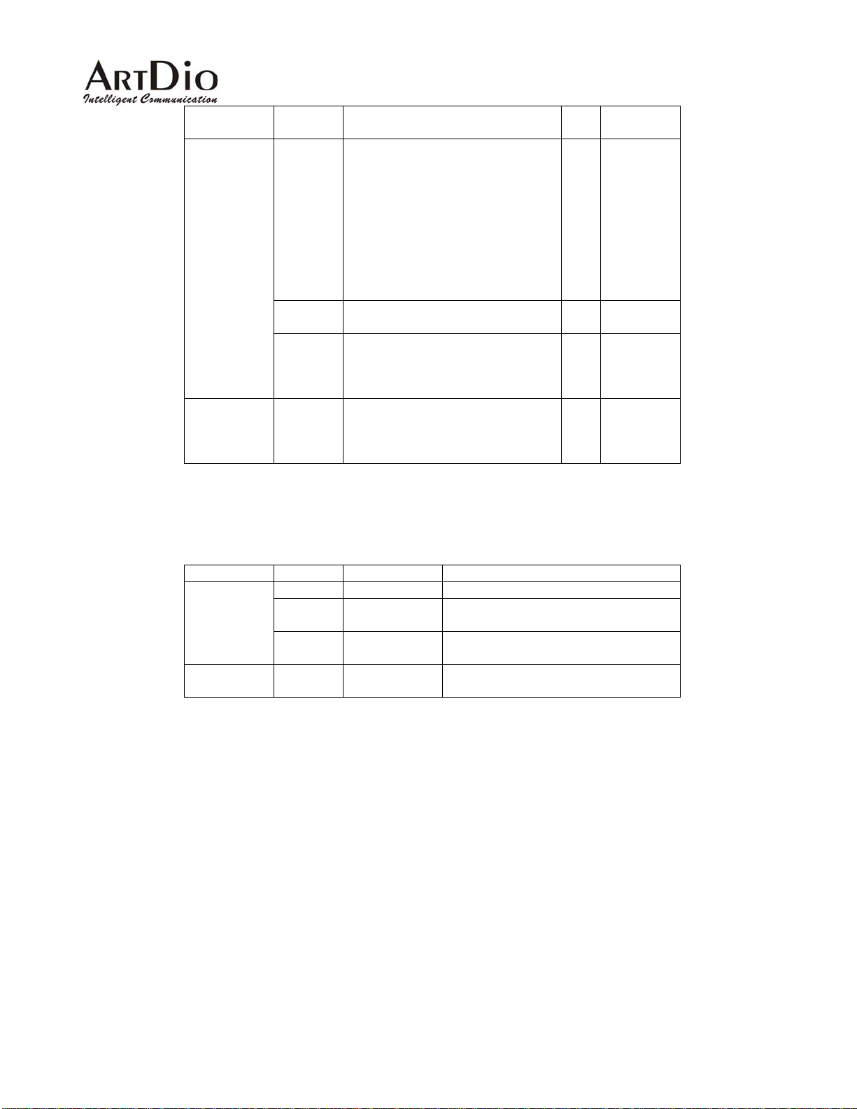
Category Entry Description Data
Range
Type
Information
IP State Defines the mode used to acquire
an IP address:
RW
Manual
Auto (DHCP)
Manual: static address mode. The
system administrator must assign
the IP address directly from the
system console or web page.
Auto (DHCP): If this mode is
selected, the IP will be
automatically obtained from the
DHCP server.
Now Displays the current IP address,
RO -
subnet mask and default gateway.
Next Sets the IP address, subnet mask
RW IP address
and default gateway that will be
used (after a restart is issued) if the
IP state mode is set to manual .
DNS server
IP
Address
The IP address of DNS server , that
MGCP protocol can use the
RW IP address
domain name instead of IP
address.
Console Commands
Category Entry Console Mode Console Command
Information
DNS
IP State configuration
IP
configuration
Address
Default
configuration
Gateway
DNS
configuration
server
ip state <user | dhcp>
ip address <ip address>
<subnet mask>
ip default-gateway <ip
address>
dns <ip address>
61
Page 62
4.4 Channel Management
Channel numbers and naming: There are up to 16 channels that PBX gateway can support and the
minimum port density is two. For large port number serie s, the port naming is given in 4 port s a group.
For 7-inches series, the port naming are given as its sequence.
19-inches and 12 inches models
Sequence Name Sequence Name
port 1 1/1 port 11 3/1
port 2 1/2 port 12 3/2
port 3 1/3 port 13 3/3
port 4 1/4 port 14 3/4
port 5 2/1 port 15 4/1
port 6 2/2 port 16 4/2
port 7 2/3 port 17 4/3
port 8 2/4 port 18 4/4
7-inches model
Sequence Name
port 1 1
port 2 2
port 3 3
port 4 4
4.4.1 Summary
62
Page 63
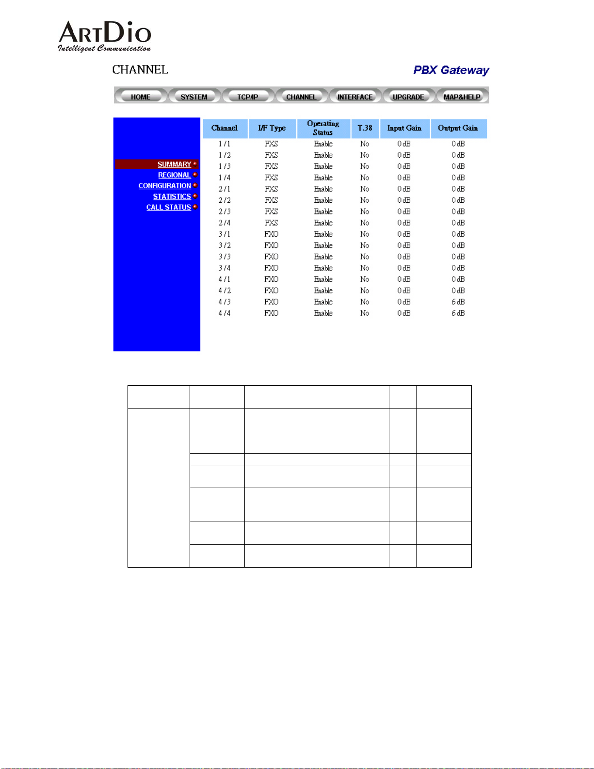
Category Entry Description Data
Range
Type
Summary
Channel
The channel number. It displays
Group/Port format. Port 2 in
group 1 will be shown as 1/2
RO Two groups
and 4 ports
for each
group
I/F Type
Operating
Status
T.38
Shows the port interface type. RO FXS, FXO
Shows the operation status of
this port. Enable/Disable
Whether or not this port is
configured to support the T.38
RO Enable
Disable
RO Enable
Disable
Fax relay
Input Gain
Shows the currently configured
RO -6 db to 6 db
input gain
Output
Gain
Shows the currently configured
output gain
RO -6 db to 6 db
62
Page 64

Console Commands
PBX Gateway - PBX Gateway#sh channel
group port mode admin operation vad T.38 input gain output gain
----- ---- ---- ------- --------- ------- ---- ---------- -----------
1 1 FXS enable enable enable No 0 0
1 2 FXS enable enable enable No 0 0
1 3 FXS enable enable enable No 0 0
1 4 FXS enable enable enable No 0 0
2 1 FXS enable enable enable No 0 0
2 2 FXS enable enable enable No 0 0
2 3 FXS enable enable enable No 0 0
2 4 FXS enable enable enable No 0 0
3 1 FXO enable enable enable No 0 0
3 2 FXO enable enable enable No 0 0
3 3 FXO enable enable enable No 0 0
3 4 FXO enable enable enable No 0 0
4 1 FXO enable enable enable No 0 0
4 2 FXO enable enable enable No 0 0
4 3 FXO enable enable enable No 0 0
4 4 FXO enable enable enable No 0 0
63
Page 65
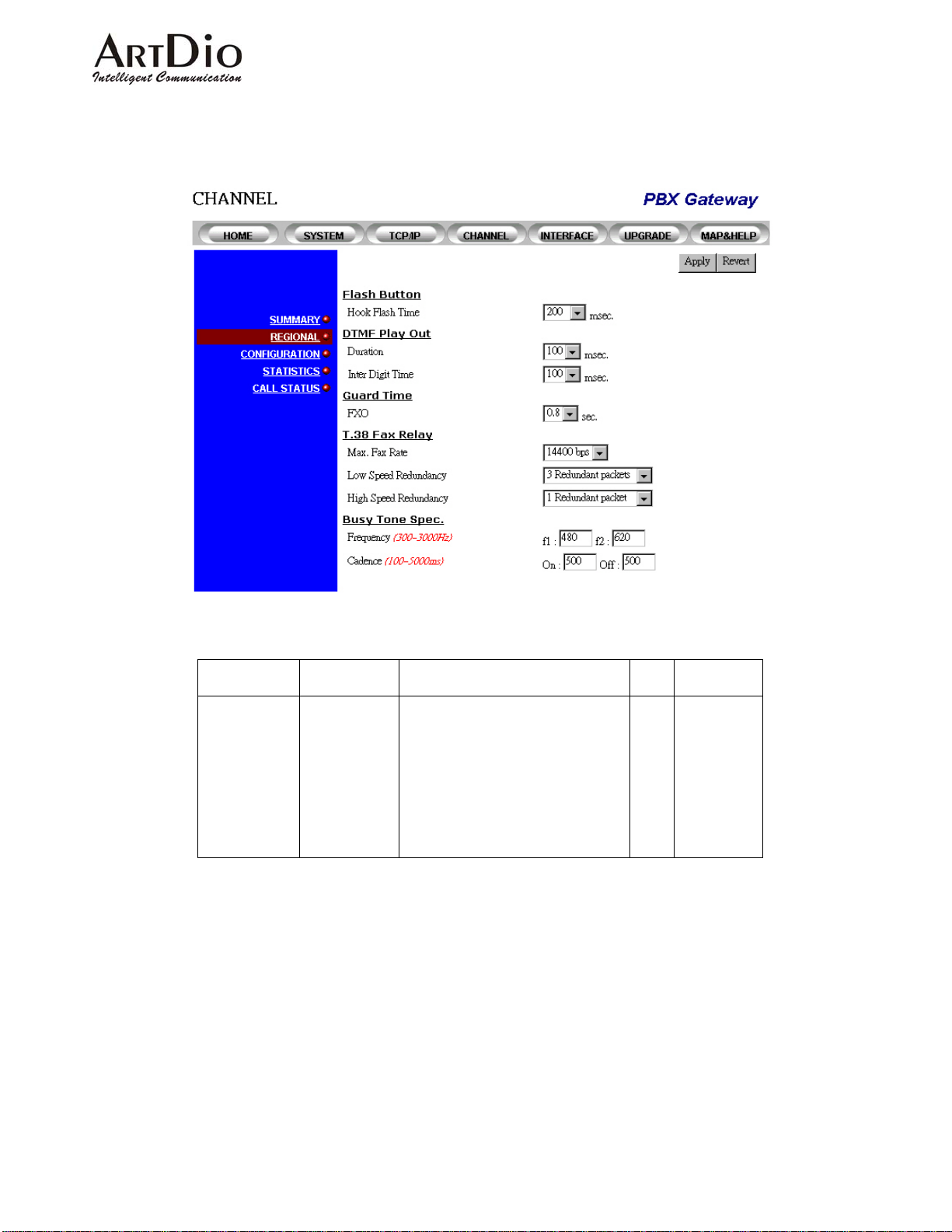
4.4.2 Regional
The configuration shown in this page applies to each channel on the entire device.
Category Entry Description Data
Type
Information
Hook Flash
Time
Defines the time frame of a break
that is to be treated as a Flash
signal.
RW
Range
200ms
300ms
400ms
500 ms
600 ms
700 ms
800 ms
900 ms
1000 ms
64
Page 66

Category Entry Description Data
Type
DTMF Play
out
Duration Defines how long the DTMF will
be sent when the gateway
RW
receives a DTMF Play Out
message from the Call Ag ent.
Inter Digit
Time
Defines the inter-digit time of the
DTMF when the gateway
RW
receives a DTMF Play Out
message.
Guard Time
FXO The amount of time specified to
RW 0.4, 0.6,
prevent the FXO interface from
terminating the connection while
receiving a ring signal that is
going to finish a all or a clearing
signal that is going to terminate
the call session. In this instance,
T.38 Fax
Relay
Max. Fax
Rate
the FXO should not answer the
phone.
The maximum data rate that is
allowed to transmitted for FAX
18
RW 2400, 4800,
transmission.
Low Speed
Redundancy
Number of redundant packets
that must be sent out while being
RW No, 1, 2, 3,
transmitted at low speed.
High Speed
Redundancy
Number of redundant packets
that must be sent out while being
RW No, 1, 2
transmitted at high speed.
Busy Tone
Frequency
f1, f2
RW (300 ~
Spec
Cadence on, off The on and off duration in
RW (100 ~
playing the tone
Range
100
150
200
250
300
350
400
450
500
550
600
650
700
750
800
100
150
200
250
300
350
400
0.8, 1.0,
1.2, 1.4,
1.6, 1.8,
2.0, 2.2,
2.2, 2.4,
2.6, 2.8, 3.0
7200, 9600,
12000,
14400 (bps)
4, 5
(Redundant
packets)
(Redundant
packets)
3000Hz)
5000ms)
Console Commands
18
Someone called this clearing signal "ring off" which is a signal that tells the other party that this call is terminated. This ring signal is different
from the "ring in" signal that does not have an on and off sequence as cadence, instead, it will be a short ring and will not repeat.
65
Page 67

Category Entry Console Mode Console Command
Information
DTMF Play
out
Flash Time Channel
Duration
Inter Digit
Flash <200 – 1000>
Not supported in the console
Not supported in the console
Time
Busy Tone
Spec.
Frequency
Cadence
There is no such function in the Command
Line Interface
66
Page 68
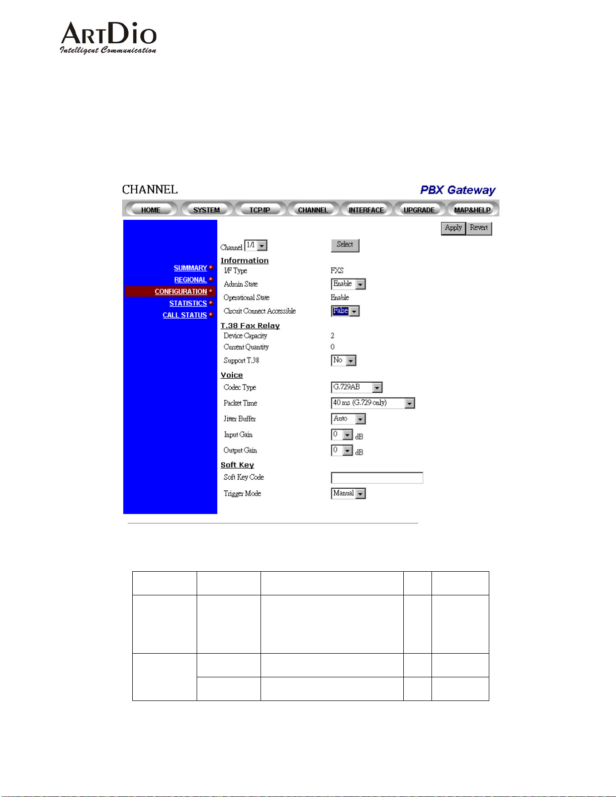
4.4.3 Channel Configuration
The configuration shown in this web page applies to a single channel. You must select a channel and
configure it to your particular specifications.
Web Management
Category Entry Description Data
Information
Channel Channel number. Displays in
Group/Port format. Port 2 in
group 1 will be shown as 1/2
I/F Type Displays the channel interface
type.
Admin State Enables/disables the channel. RW Enable,
67
Range
Type
RW One or two
groups and
4 ports for
each group.
Default: 1/1
RO FXS or FXO
Disable
Page 69

Category Entry Description Data
T.38 Fax
Relay
Operational
State
Device
Capacity
Displays the current operational
states.
The maximum number of
channels that are permitted to
be configured to support the
T.38.
Current
Quantity
The number of channels that
are currently configured to
support the T.38.
Support T.38 Enables/disables the T.38
support on this channel.
Voice
Codec Type Assigning the preferred port
codec type.
Packet Time Defines how long the gateway
will send a voice packet to the
destination port.
Please refer to the Available
Packet time selection table.
Input Gain Input gain selection. RW -6, -5, -4, -3,
Output Gain Output gain selection. -6, -5, -4, -3,
Range
Type
RO Enable,
Disable
RO
2
(Only two
channels
are allowed
to support
T.38)
RO 0, 1, 2
RW Enable,
NO
G .71 1 A Law ,
RW
G. 711 u Law,
G.729AB
10ms –
RW
G.711,
20ms –
G.711, G.729A,
30ms G.711,
40ms G.729A,
60ms G.729A,
80ms G.729A
-2, -1, 0, 1,
2, 3, 4, 5, 6
db
-2, -1, 0, 1,
2, 3, 4, 5, 6
db
Table: Available packet time supported by different coding type
Codec Types 10ms 20ms 30ms 40ms 60ms 80ms
G.711
G.729A
√ √ √
√
√ √ √
68
Page 70
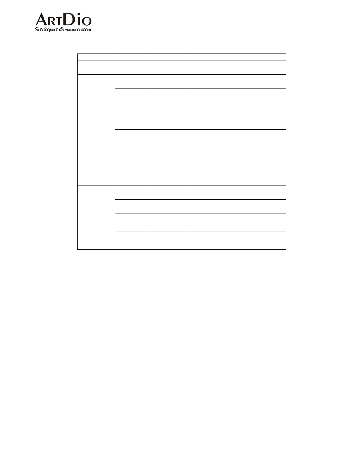
Console Commands
|
|
Category Entry Console Mode Console Command
Information
Fax
Voice
Admin
State
Enable/Di
sable
Redundan
cy at high
Channel
Channel
Configure->Fa
x
channel <group/port> <enable
| disable>
t38_fax <group/port> <enable
| disable>
fax high_redun <0-2>
(default=1)
data rate
Redundan
cy at low
Configure-Fax
fax low_redun <0-5>
(default=3)
data rate
Maximum
Transmit
Rate
Configure-Fax
fax rate 2400 (2400bps)
4800 (4800bps)
7200 (7200bps)
9600 (9600bps)
12000 (12000bps)
14400 (14400bps)
Show Fax
Show Fax
show fax
Configurat
ion
Codec
-
Not supported
Type
Packet
-
Not supported
Time
Input
gain
Output
Gain
Channel
Channel
gain input < group/port> <-6
-5 | -4 | -3 | -2 | -1 | 0
1 | 2 | 3 | 4 | 5 | 6>
gain output <group/port> <-6
| -5 | -4 | -3 | -2 | -1 | 0
| 1 | 2 | 3 | 4 | 5 | 6>
69
Page 71
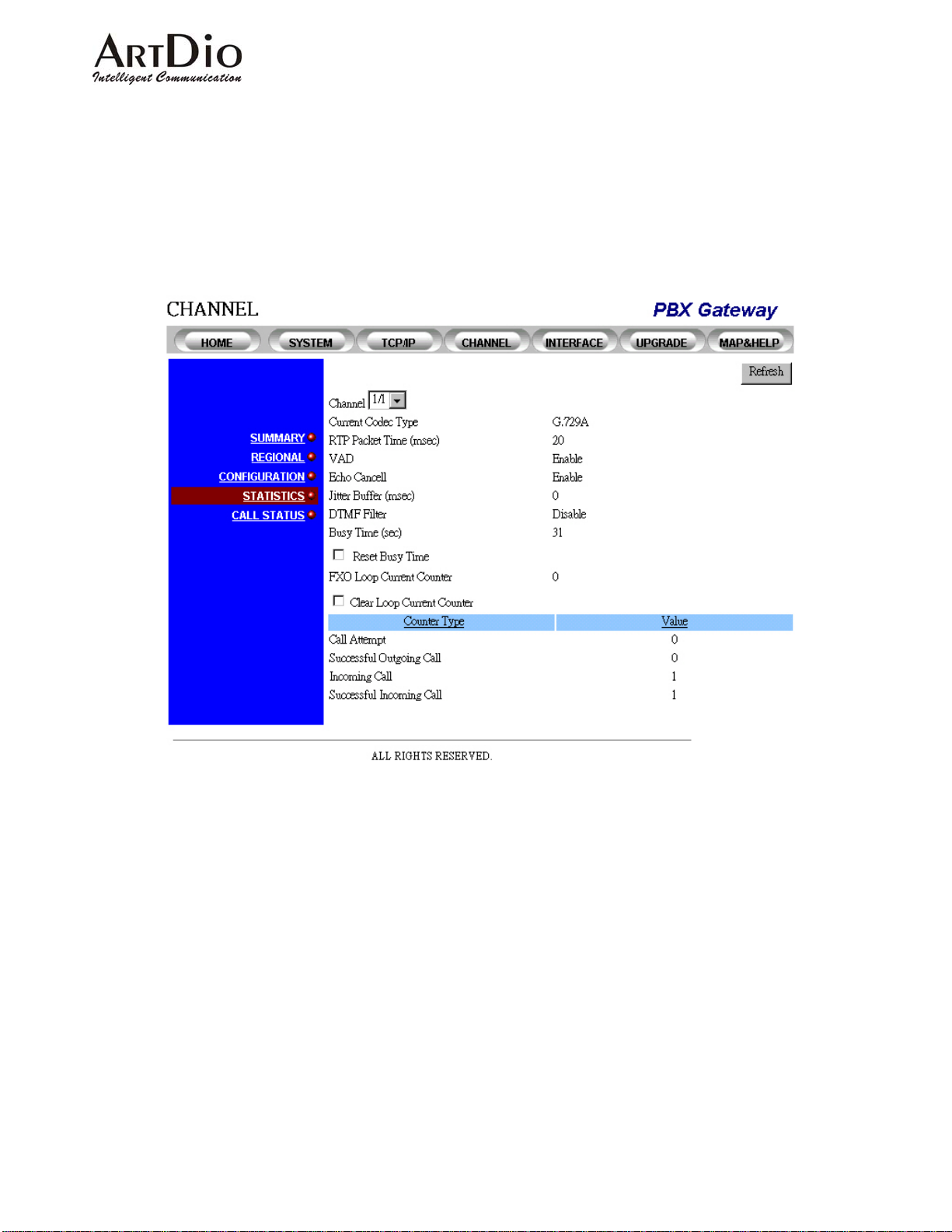
4.4.4 Statistics
This web page shows the configuration and stati stical information of each channel. You only have to select
a channel number and click the refresh button. The gateway will then return a page showing its current
configuration and statistical data.
Web Management
70
Page 72
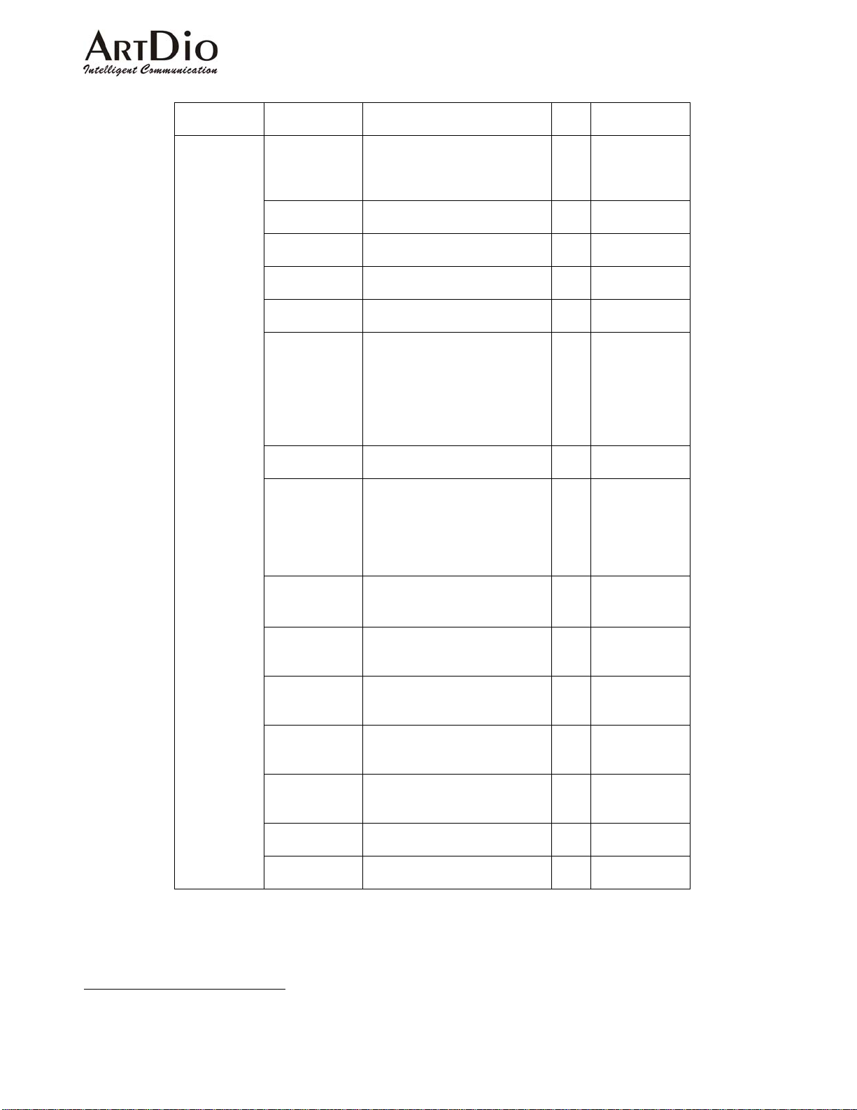
Category Entry Description Data
Type
Channel The channel number. Shown
RW Two groups
in the Group/Port format. Port
2 in group 1 will be shown as
1/2
Current Codec
Type
Packet Time
(msec)
VAD Displays VAD administrative
Displays the current codec in
use by the channel
Displays the current packet
time in use by the channel
RO
RO
RO
status
Echo
Cancellation
Jitter Buffer
(msec)
Displays Echo Cancellation
administrative status
Displays how long the jitter
buffer is used in this channel.
RO
RO
If the channel has received no
traffic, the last value that was
used by the previous call will
be displayed. 0 stands for
AUTO jitter buffer.
DTMF Filter Displays DTMF Filter
administrative status
Busy Time
(sec)
Displays the length of time
this channel has beenbusy .
RO
(Includes incoming and
outgoing calls.)Busy time will
be reset when you switch off
the power .
Reset Busy
Time
Check box. If checked and the
refresh button is then clicked,
RW
Busy Time will then be re set.
FXO Loop
Current Lost
Counter
19
Clear Loop
Current
Displays the number of
counter that FXO interfaces
can not detect loop current
To reset the FXO Loop
Current Counter back to zero
RO
RW
Counter
Call Attempt Displays the number of call
RO
attempts that have been
made.
Successful
Outgoing Call
Displays the number of
successful outgoing calls that
RO
have been made.
Incoming Call Displays the total number of
RO
incoming calls
Successful
Incoming Call
Displays the number of
successful incoming calls
RO
Range
and 4 ports for
each group.
1/1
19
If the counter is greater than "0", then the Red alarm LED on the front panel will be lit. After it is cleared, the Red Alarm LED will go off.
71
Page 73
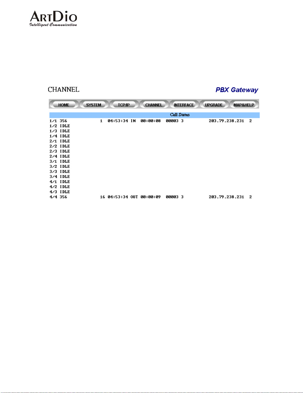
4.4.5 Call Status
This web page shows the activities that are currently being performed on each port. Users must refresh
the screen manually to check the current port activities. The formats that are di splayed here are exactly
the same as the CDR that shows from CDR ports (see Chapter 10 The Call Detail Record information)
Web Management
Command Line Interface
This function is not provided through any command line interfaces such as the Console or Telnet.
Fig 15 Call Status Screen
72
Page 74
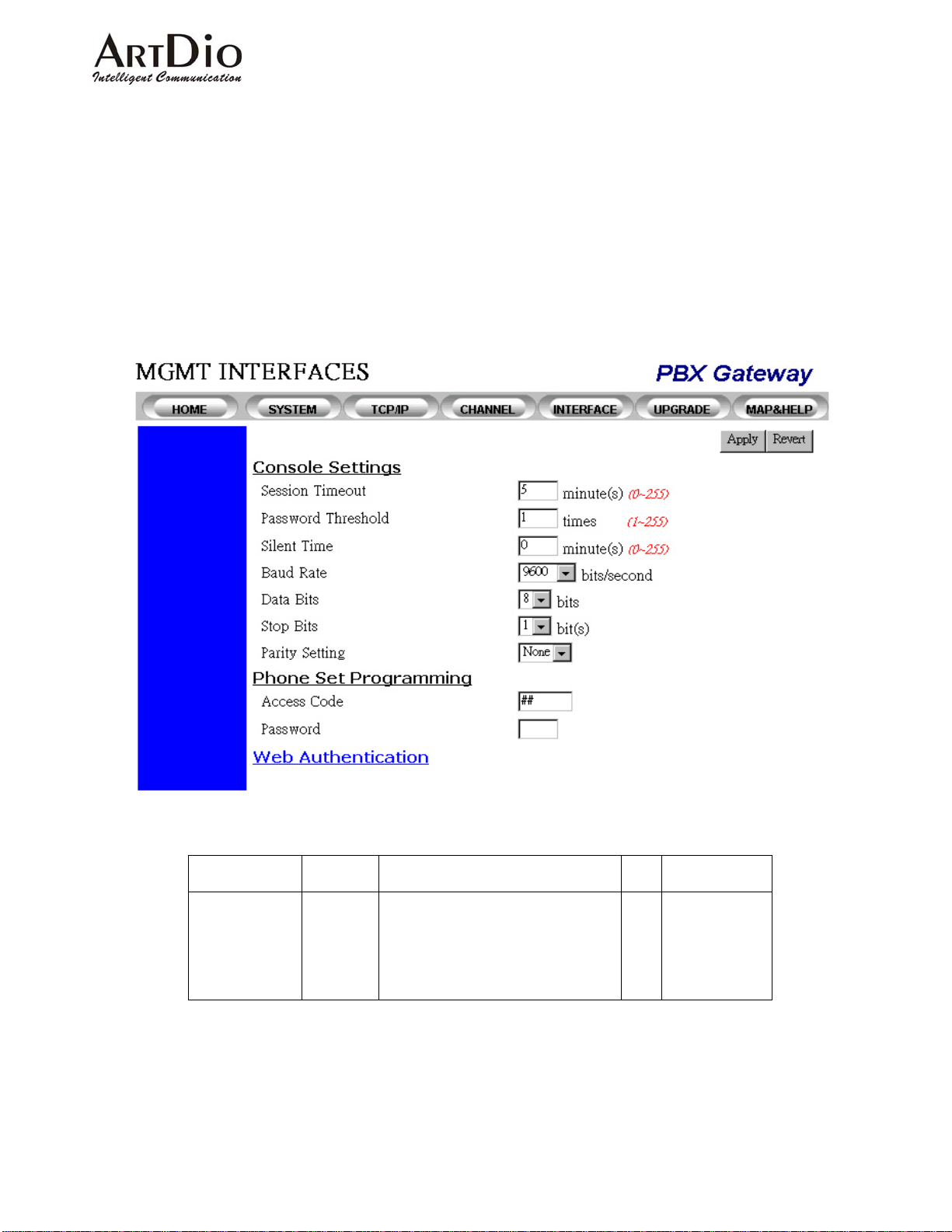
4.5 Management Interfaces
PBX VoIP Gateways are flexible with the Web Management Interface, Console Management Interfaces
(through RS-232), Telnet and Phone Set Configuration Interfaces. You can configure the parameters for
different management interfaces through the web management interface or through the management
interface itself. Following is a demonstration on how it can be configured:
4.5.1 Web Management
Category Entry Description Data
Console
Setting
Session
Timeout
A session (system console or
Telnet) will be automatically
logged-out if the activity timer has
exceeded the maximum timeout
value. The value 0 stands for no
timeout.
73
Range
Type
RW 0 – 255
minutes
(Default:5)
Page 75

A
Category Entry Description Data
Range
Type
Password
Threshold
The session will be halted if the
number of invalid password tries
RW 0 – 255
(Default:1)
has reached the threshold. Please
note that it applies only to the
console and Telnet, it does not
apply to the web interface. The
value of 0 stands for no password
threshold.
Silent
Time
Baud Rate System console bau d rate
Determines how long the console
will halt when the invalid password
tries have reached the threshold.
selection. If the baud rate is set to
any rate other then 9600 you will
see a string of garble in the
RW 0 – 255
minutes
(Default:0)
RW 2400,
9600,
19200,
38400
terminal during system boot up.
The console goes back to normal
after boot up. This is because the
system is set at 9600, 8, 1, N
during boot up. Therefore it is
highly recommended to configure
the system console to 9600 baud.
Data Bits Data bits selection RW 7, 8 bits
Stop Bit s Stop bits selection RW 1, 2 bits
Phone Set
Programming
Access
Code
The Access Code to start the
Phone Set Programming Mode
(see 5 Phone Set Interface
Configuration Procedures for more
RW ## as default,
1-6 digits, the
first digit can
be "#" or "*"
detailed information)
Web
Authentication
Password The password required to enter the
Phone Set Programming Mode
after entering the Access Code
User
Name
The Authentication ID to begin the
Web Management Interface. The
Read & Write account can rea d
and write information via a Web
browser . The Read only account
can read information only.
RW 0000 as
default,
1-4 digits
RW WEB as
default for
Read and
Write, BLANK
for read only
1-12
characters in
string format
Password The Password for the
uthentication ID to begin the Web
Management Interface
WO Empty
password as
default, Allow
string up to 6
characters
Confirm
Password
Re-enter the Password for the
Authentication ID to confirm
access into the Web Management
Interface
WO Empty
password as
default, Allow
string up to 6
characters
74
Page 76
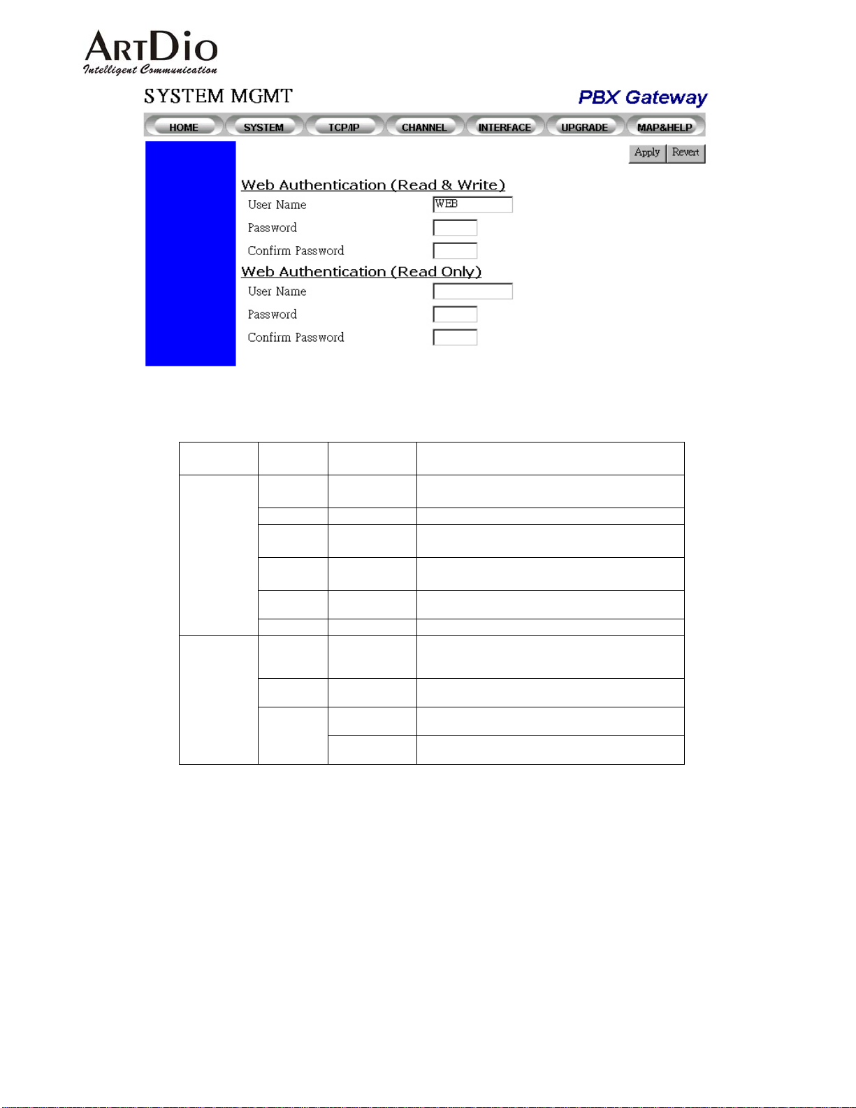
|
4.5.2 Console Commands
Category Entry Console
Line
Console
Password
Session
Timeout
Data bits Console
Password
Threshold
Silent
Time
Baud Rate Console
Time Out Console
Console
Level
Phone Configuration
Web
Mode
Console
Console
Console
Configuration
Configuration
Configuration
Console Command
time-out <0-255> in minutes
data bits <7/8>
password-thresh <0-255>
silent-time <0-255> in minutes
speed <2400 | 9600
>
time-out <0-255> in minutes
password console [read|write]
<password> in 6 characters for
"enable"
password phone digits in 4 digits
(0~9, default is 0000)
password web_read username
<username> in 6 characters
password web_write password
<password> in 6 characters
19200 | 38400
75
Page 77
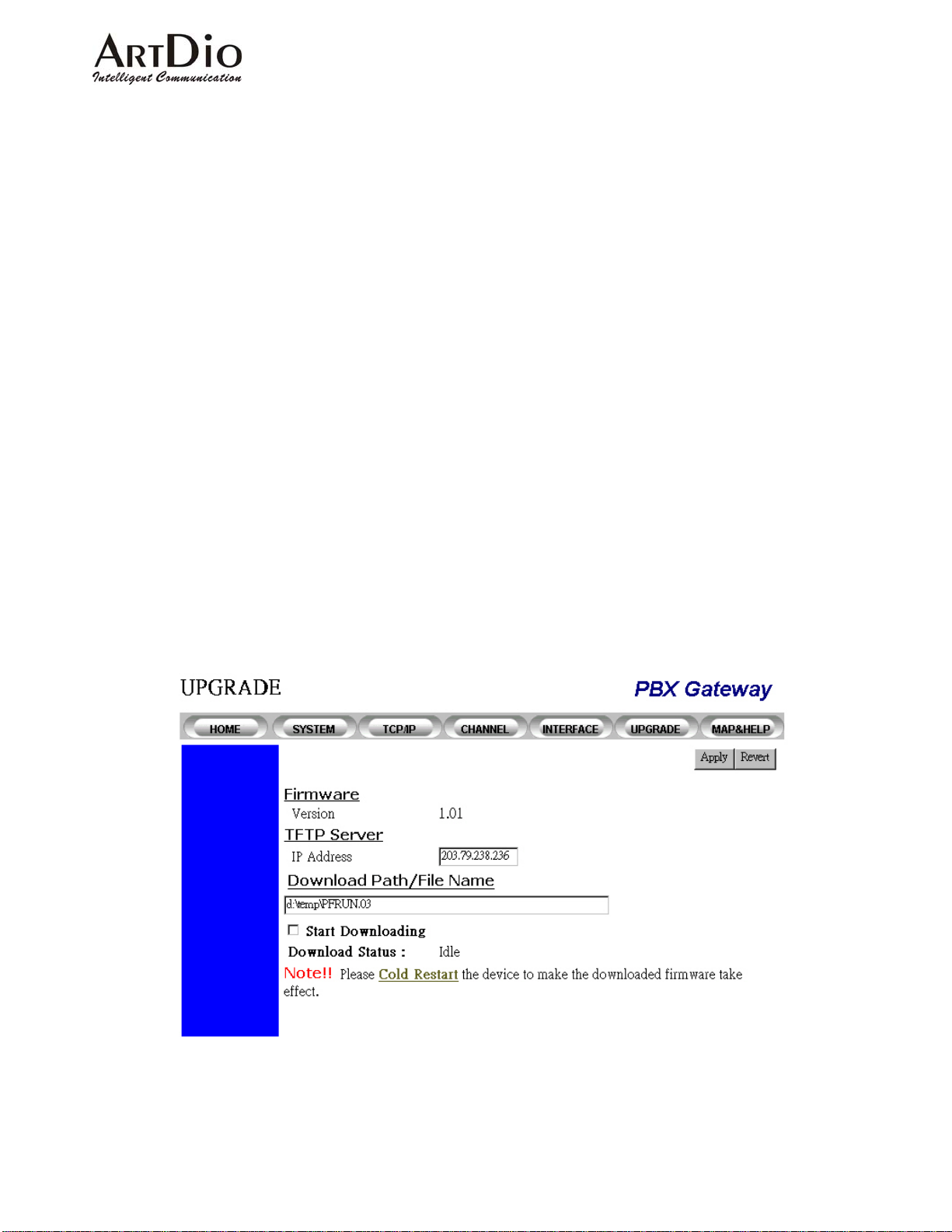
4.6 Software Upgrade
The software upgrade can only be done through a TFTP server, therefore you must have a TFTP server
running on the network and the new firmware must be saved on the server. You can issue a command to
download it from the web management page or system console. The following steps are a guide to
downloading the new firmware from the TFTP server through a web interface.
Step 1. Make sure the TFTP server is running and the newly received firmware is saved on the server.
Step 2. Fill in the IP address of the TFTP server and the path/filename information.
Step 3. Check the Begin Downl oad box
Step 4. Click the Apply button to start downloading the firmware. The gateway will display a page with the
download status showing: in-progress
Step 5. You can check the download status by manually clicking the Apply button repeatedly and holding
until the return page shows a successful download. If the gateway cannot find the TFTP server or
the filename, the download status in the returned page will show Time-out or Error.
Step 6. After the code has been successfully downloaded, you have to initiate a cold-start. The new code
will not take effect until you issue a cold-start command. You can issue a cold-start command
through the system console or through the web management pag e in the System Management.
76
Page 78
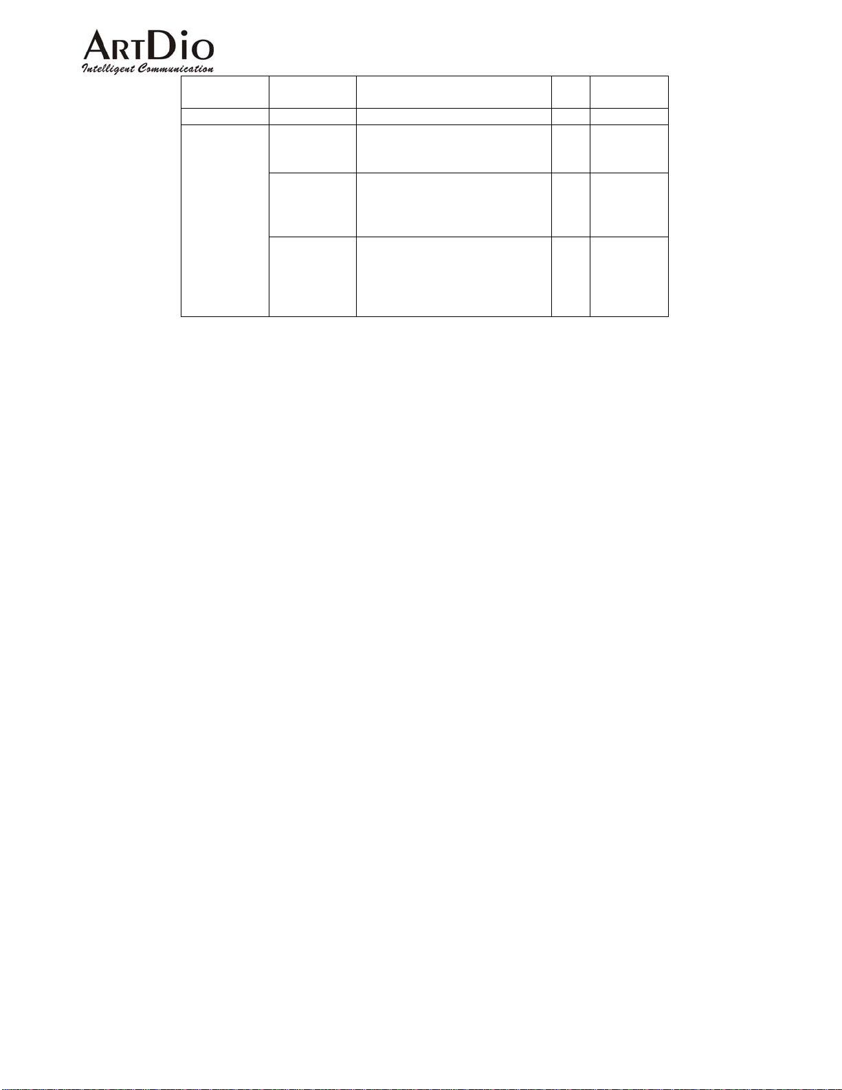
Category Entry Description Data
Firmware
TFTP Server
Version Displays the firmware version RO
IP Address Specifies the IP addre ss of the
TFTP server . A domain name is
also allowed.
Download
Path/File
Name
Specifies the path of the
filename in the TFTP server
such as:
C:/runtime.tcw
Start
Downloading
A check b ox to enable the
system to begin downloading.
When checked and apply is
clicked, the system will
commence downloading.
Range
Type
RW IP address
and domain
name
RW String up to
48
characters
RW
77
Page 79

4.6.1 Console Commands
Using the system console to upgrade the firmware is quite similar to using the We b management interface.
You must run the TFTP server first. You must also assign the IP address of the TFTP server and filename
separately . After they are configured, issue a copy command to initiate the firmware upgrade. You can also
combine three commands into one. Following these steps:
Step 1: Configure TFTP server and filename
a) Separate command:
1. PBX Gateway(config)# tftp server <ip-address | domain name>
2. PBX Gateway(config)# tftp filename <filename>
3. PBX Gateway(config)# exit
4. PBX Gateway# copy tftp:///
b)Combined command
copy tftp://<ip-address>/<filename>
PBX Gateway(config)#copy tftp://192.168.0.201/a:\runtime.tcw
TFTP Server: 192.168.0.201
a:\runtime.tcw
Downloading….
Step 2: The Gateway should now be downloading the firmware. Wait for the result.
PBX Gateway(config)#copy tftp://192.168.0.201/a:\runtime.tcw
TFTP Server: 192.168.0.201
a:\runtime.tcw
Downloading....
Download success
System must reload
Step 3: If the gateway downloaded the firmware successfully, issue a cold-start to launch the new code.
PBX Gateway(config)#reload
78
Page 80

Category Entry Console Mode Console Command
TFTP Server
IP
Address
Download
Path/File
Name
Start
Downloadi
ng
Configuration
Configuration
Privileged Two commands (If the TFTP server IP
tftp server <ip-address |
domain name>
tftp filename <filename>
address and filename have already
been assigned):
copy tftp :///
Or specify the address and file name
at the same time:
copy tftp ://<ip-address>/
<filename>
If the TFTP server IP address and
filename have been assigned:
If the TFTP servers IP has not been
assigned You may specify the
address and file name
simultaneously:
4.7 Additional Console Commands
Comands Purpose
area
auto_attn
call_route
cdr
code
country
cut_through
dbflush
delete nvram
dial_code
exit
end
extension_len
fax
gid_tmr
greet_mode
Sets the device’s area code
Sets the auto attendant status
Sets or deletes an entry in the routing table
Enables or disables the CDR log
Enters the access code configuration mode
Sets the device’s country code
Sets the access code to skip the greeting message on this
device.
Immediately saves the current configuration onto non-volatile
memory. It is recommended that you issue this command
after entering configuration changes. The system will
automatically execute this command if it has detected no
input within a certain time frame.
Resets the configuration to the default value. Also known as
a Factory Reset.
delete nvram
Sets the access number for out-bound analysis
Exits the current mode and returns to a higher level
Returns to Privileged mode
Sets the number of digits for the PBX extension
Sets the T.38 Fax relay configuration
Timer to erase the group id when system shuts down
Sets the device’s greeting mode
79
Page 81

group_id
master_ip
internal_ac
intn_code
local_pstn_ac
long_distance
office_excp
oper_code
pend-restart
pin
ping
prefix
probe-hook
probe-remove
prog_ac
region_id
rtp_base
retransmit
service_port
show ac_summary
show call_route
show channel
show date
show ethernet
show flash
show history
show ip
show line
show location
show pin
show routing-config
show running-config
show service_port
show slave
show tftp
show time
show version
slave
t38_fax
tcwarn_time
transit_ac
transit_call
udp_port
vad
Sets the group ID
Sets the master's IP address
Sets the internal access code for inter-gateway calls
Sets the international access code for in-bound analysis
Sets the local PSTN trunk access code (if it exists)
Sets the long distance access code for in-bound analysis
Sets the long distance access code for in-bound analysis
Sets the code to reach the operator of the PBX system
Perform warm start while system is idle
Sets or deletes a pin code
Checks the IP configuration or network connections
Sets the device’s prefix number
Enable cadence probe state
Disable cadence probe state
Sets the device’s phone set program mode access code
Sets the region/ID information for the proper ringing pattern,
cadence and other regional related profiles
Sets the RTP base port nu mber
Sets the call retransmit count
Sets the Service port for Telnet or Web
Shows a summary of the access code configurations
Shows the device’s routing table
Shows the channel summary
Shows the date
Shows Ethernet information
Shows the flash time settings
Shows the previous commands that were issued
Shows the IP settings
Shows the console settings
Shows the location information
Show all pin codes for transit calls
Shows the device’s current operating routing mode
configuration
Shows the current running configuration
Shows the service port for Telnet or Web
Shows the slave device (if the device is set to master)
Shows the TFTP server’s IP address
Shows the current time
Shows the firmware version
Sets or deletes a slave device
To add/del channels to support the T.38 Fax function
Sets the transit call warning time
Sets the transit access code
Enables or disables the device’s transit call
Sets the UDP port number
Enable or disable the voice activity detection
80
Page 82
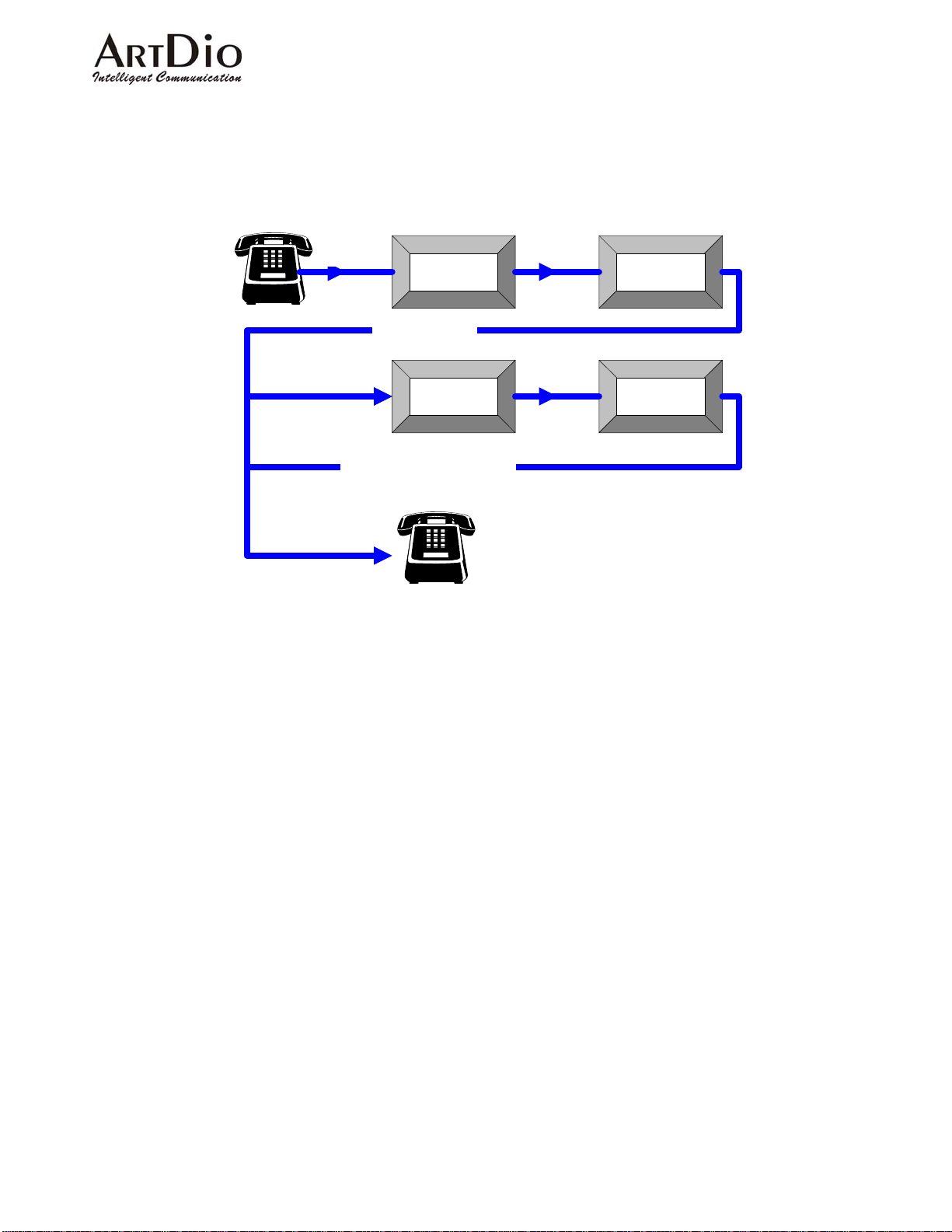
5. Phone Set Interface Configuration Procedures
5.1 Configuration procedures
Dial Tone
Hook Off
Confirmation Tone
Confirmation Tone/Reject Tone
PROG
Access Code
Item
2 Digits
Hook On
Note 11 Use "#" as the ending prompt for the data entry.
Password
Data
Note 12 The (factory default) value PROG Access Code is "##" and the (default) password is "0000".
Note 13 The default confirmation tone is "doo…doo...doo"
81
Page 83
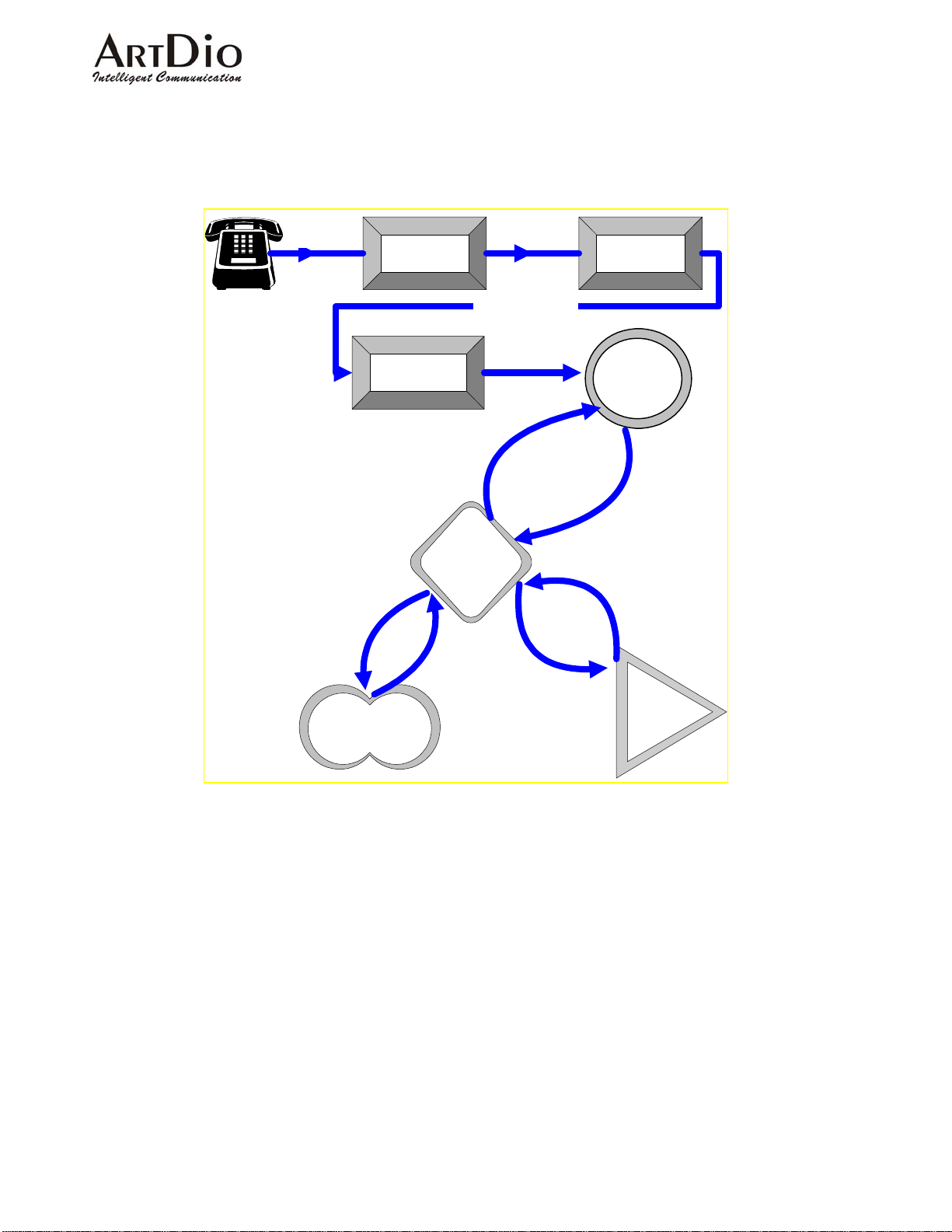
5.2 Greeting Message Recording Procedure
Hook Off
Dial Tone
Press 9#
Access Code
99 -item code
to recording
Save the
recording to
FlashROM
PROG
mode
Confirmation
Confirmation Tone
Store
Recording
Message
Temporarily
tone
Press #
Press 0
Password
Press *
to start
recording
Press #
Press #
Play
temporary
recording
To record the greeting message into the PBX gateway, the user must switch to the recording mode after
entering the Phone Set Configuration mode and pressing the item code “99”. If the user has already
recorded a greeting message, he or she can use the item code “96” to hear it.
In the recording mode, to prevent accidental use the recorded voice will not be stored automatically. You
must press "*" to start recording then "#" to stop recording. You can check your recorded message by
pressing "0", if the recording is satisfactory, press "9#" to store it onto none vanished memory (NVRAM), it
will take few seconds to
save the greeting message and give you confirmation tone if the action is done.
The recorded message can be uploaded to or downloaded from the PBX gateway by using an FTP client
application.
82
Page 84
5.3 Configurable Items
5.3.1 Data Range
Syntax for the data descriptions:
In the Phone Set Programming Mode, all data entered is a combination of the 12 keys shown on the
keypad on the phone set panel.
x or 0|1|2|3|4|5|6|7|8|9: Digits that range from 0 to 9
'*': Keypad "*"
'#': Keypad "#"
f(0 ~ 9): Digits that range from 0 to 9
f(0~9, *, #): String with digit s that ran ge from 0 to 9 or characters * and #.
xf(0~9): x number of digits using digits t hat range from 0 to 9. For example, 4f(0~9) means a four digit
123
456
789
*0#
number like 0000, 1111, 1234, 9999 etc.
[x
]f(0~9): Number of x1 to x2 digits and the range of digits is from 0 to 9. Example, [1,2]f(1~9) means a
1,x2
number of one or two digits, and the digits used are between 1 to 9, like 12, 22, 34, 1, 2 etc. But
does not include 01, 02, 10, 20 etc.
+: Compound operator, which combines more than one definition into a string of digits. Example, f(0~9, *,
#) + [1,5]f(0,9) means that this is a string that has at least one character with the range f(0~9, *,#)
and then 1 to 5 digits as the compound result.
5.3.2 Configurable Items
Code Description Data after item code
01 DHCP Status 0 : Disable ; 1: Enable
02 IP Address xxx,'*',xxx,'*',xxx,'*',xxx
03 Subnet Mask xxx,'*',xxx,'*',xxx,'*',xxx
04 Default Gateway xxx,'*',xxx,'*',xxx,'*',xxx
05 Group ID [1,10]f(0~9), the number is between 0 to
06 Master IP Address xxx,'*',xxx,'*',xxx,'*',xxx; 0.0.0.0 if this
2147483647.
gateway is the master, and it is the
83
Page 85
A
default value.
07 Country Code
08 Area Code
09 Prefix Code
10
dd an Inbound International Access
[1,3]f(0,9)
[1,3]f(0,9)
[1,4]f(0,9)
[1,3]f(0,9)
Code
11 Deletes an Inbound International
[1,3]f(0,9)
Access Code
12 Outbound International Access Code
13 Long Distance Access Code (adds
both In-bound and Out-bound)
20
14 Internal Call Access Code
15 Transit Call Access Code
16 Program Mode Access Code
17 Sets the Local PSTN Access Code
18 Deletes the Local PSTN Access
[1,3]f(0,9)
[1,3]f(0,9)
1f(0~9,*,#)+[1,5]f(0~9)
1f(0~9,*,#)+[1,5]f(0~9)
1f(0~9,*,#)+[1,5]f(0~9)
1f(0~9,*,#)+[1,5]f(0~9)
1f(0~9,*,#)+[1,5]f(0~9)
Code
19 The MGCP Trunk Access Code
20 Adds a Routing Entry
1f(0~9,*,#)+[1,5]f(0~9)
[1,6]f(0~9,*,#)+*+[1,2]f(0~9);
(as Entry * Cost)
21 Deletes a Routing Entry
[1,6]f(0~9,*,#)
22 Adds a Member 6f(0~9,*1,*2,*3,*4), which are the last 6
characters of the MAC address and
*1,*2,*3,*4,*5, *6 means A, B, C, D,
E, F in hexadecimal
23 Deletes a Member 6f(0~9,*1,*2,*3,*4), which are the last 6
characters of the MAC address and
*1,*2,*3,*4, *5,*6 means A, B, C, D,
E, F in hexadecimal
24 Transit Call Status 0 : Disable ; 1: Enable
25 Adds a PIN Code
26 Deletes a PIN Code
[1,8]f(0~9)
[1,8]f(0~9)
27 Auto. Attendant Status 0 : Not Provided ; 1: Provided
28 PBX Extension Digit Length
1f(1~9)
29 Greeting Status 0 : Default ; 1: Recording
30 Skips Auto Attendant Access Code
96 Plays the recorded Greeting
1f(0~9,*,#)+[1,5]f(0~9)
# Stop playing
Message
97 Password Change
4f(0~9)
98 System Restart 1: Enable
99 Enters the Greeting Message
Recording Mode
(see the Greeting Message Recording
procedures in section 5.2)
20
Most of the In-bound/Out-bound Long Distance codes are set to one, as well as the phone set interface. The number, "13", will add both
In-Bound and Out-Bound Long Distance Access codes.
84
Page 86
6. Firewall Configuration
The PBX voice gateway uses UDP packets to transmit the call control signaling between devices, it also
utilizes the normal RTP packets to transmit the voice streams. In order to allow communications to perform
even thoughthe PBX gateway is installed behind a firewall, the network administrator m ust open the required
ports and allow related protocols to pass throu gh the fire wall. The (factory default) values for the required
protocols and port numbers are as follows:
Item Protocol Port Numbers Re-configurable
Signaling UDP 2000 From WEB, Console
Voice Stream UDP (RTP, RTCP) 4000~4031 From WEB, Console
T.38 UDP 4064~4079 (Base on V oice Stream)
FTP TCP 21 Console only
Telnet TCP 23 From Console
WEB Server TCP 80 From Console
UDP Port
Channel No RTP RTCP T.38
01 4000
22
4001 4064
02 4002 4003 4065
03 4004 4005 4066
04 4006 4007 4067
05 4008 4009 4068
06 4010 4011 4069
07 4012 4013 4070
08 4014 4015 4071
09 4016 4017 4072
10 4018 4019 4073
11 4020 4021 4074
12 4022 4023 4075
13 4024 4025 4076
14 4026 4027 4077
15 4028 4029 4078
16 4030 4031 4079
21
Table 6-1 the required port numbers for the PBX voice gateway
Signaling: For out-of-band call control signaling.
Voice Streams: For voice packets.
FTP: For software upgrades and Greeting Messa ge uploads.
Telnet: For remote control.
Web Server: For remote control.
T.38 Fax Relay: For carrying packets of Fax data over IP network
21
Using the command "service_port" in the Command Line Interface to change well-known port numbers to any number you like.
22
4000 is the base RTP port number defined in user’s interfaces. If this number changed, all the mapping will changed.
85
Page 87

On some firewall systems, you are not permitted to use well-known port s, in order to maintain secu rity . In this
case, users may need to change the default port numbers to allow the PBX gateway to function. Such
modifications can be done through the Web/Console Manageme nt Interfaces (refer to
[System]->[Configuration] in Web or [Routing] configurations in the Console). After the modifications, the
system must be warm started in order for the new values to take effective. Such modifications need to be
done on each device that joins to the same routing group. In other words, they must use the same range of
ports in order to communicate with each other.
86
Page 88

7. Regulation Compliance Information
7.1 FCC
FCC Class A
This Equipment has been tested and found to comply with the limits for a Class A digital device, pursuant to
Part 15 of FCC rules. These limits are designed to provide reasonable protection against harmful
interference when the equipment is operated in a commercial environment. This equipment generates,
uses and can radiate radio frequency energy and, if not installed and used in ac cordance with the
instructions, may cause harmful interference to radio communications. Operation of this equipment in a
residential area is likely to cause harmful interference in which case the u ser will be required to correct the
interference at his/her own expense.
Warning:
A shielded-type power cord is required in order to meet FCC emission limits and also to prevent
interference to any nearby radio and television reception.
You are cautioned that changes or modifications not ex pressly approved by the party responsible for
compliance could void your authority to operate this equipment.
The RJ-45 connectors that marked "T o LAN" and "To WAN" on the front panel are used for data access
only.
The RJ-11 Connectors on the rear p anel are designed to connect to analog pho nes or analog trunks to
a PBAX, they are not intended for connection to the external TNV Communication Network (PSTN).
87
Page 89

8. Regional Tone adjustment
For most countries, the tone specifications are not the same. The differences in particular are with the
definitions for Dial Tone, Ring Back Tone, Busy Tone and Reorder Tone. In order to make the PBX gateway
capable of being installed in different countries, the device administrator can change the regional_id
according to which country the device is installed in. If he or she specifies a different regional ID, the ring,
cadence and frequency that is sent out or detected by the PBX voice gateway will be adjusted also .
The command to change the regional_id can be imputed under the Console or Telnet by CLI.
PBX Gateway>enable
PBX Gateway#config
Enter the configuration commands, one per line. End with CTRL/Z
PBX Gateway(config)#regional_id ?
<0-99> Set the value for regional id
PBX Gateway(config)#regional_id 2
PBX Gateway(config)#exit
PBX Gateway#delete nvram ?
all Select the function to delete the NVRAM
keep_ip Select the function to delete the NVRAM
<cr>
PBX Gateway#delete nvram keep_ip
(The command "delete nvram keep_ip" is functioning as the factory reset but will keep the IP
address configuration for this device and the regional_id, after doing this; you should again
re-configure the device).
After the system boot-up again, use “show run” to check the new configured regional ID.
The default value is set to "00" for the regional_id, but it may be equivalent to some of the regional_ids
listed below. This depends on which regional_id will be entered as the default value.
Regional_id Country
06 Canada
07 China
12 France
15 Hong Kong
22 Italy
23 Japan
Regional_id Country
36 Singapore
38
40
43
46
47
Slovenia
Spain
Taiwan
Great Britain
United States
Table 8-1 the table of regional IDs and their corresponding countries
88
Page 90
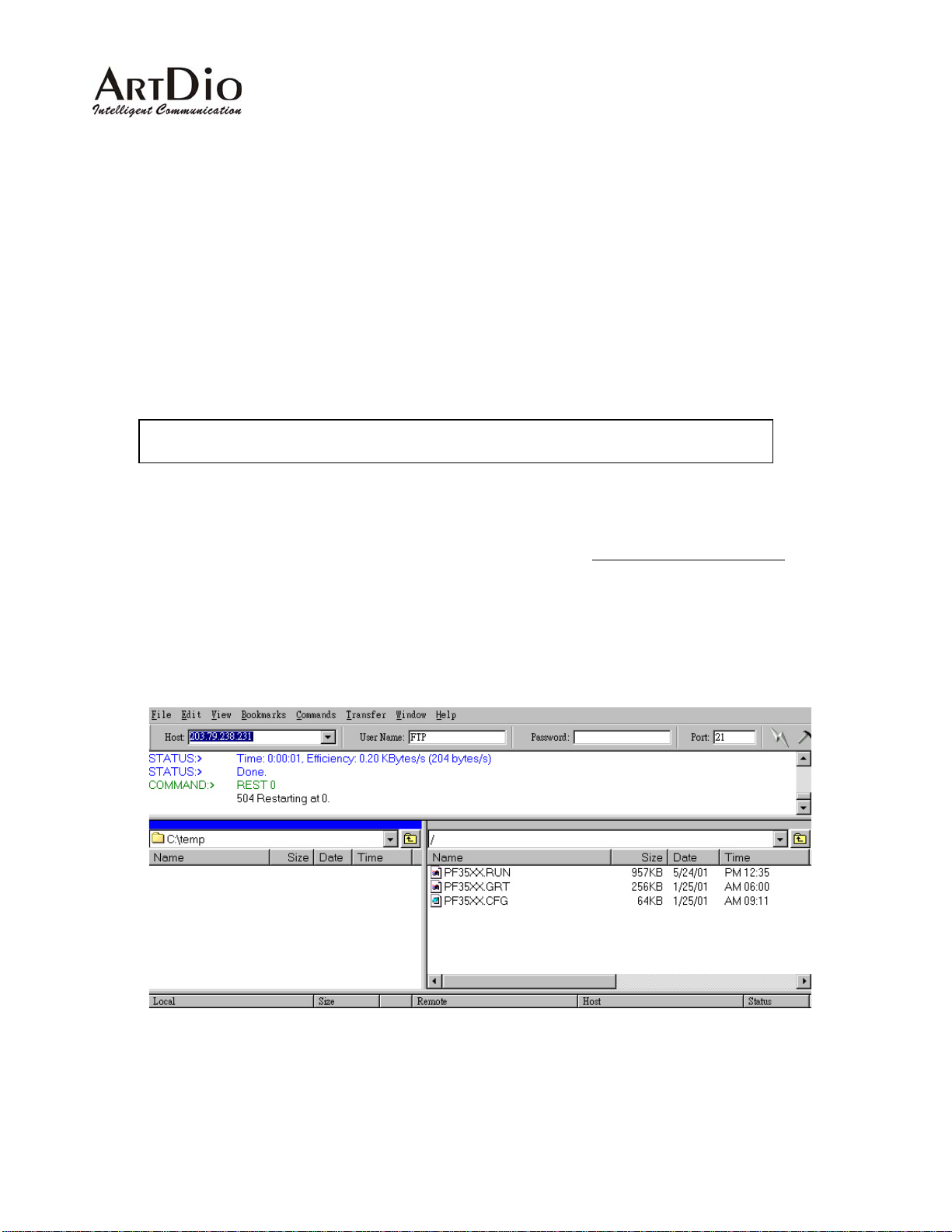
9. FTP for software upgrading, Configuration and
Greeting Message uploading/downloading
On the PBX Gateway series PBX gateway, it gives the user the option to upgrade the software using FTP,
which is less time consuming then TFTP. By using FTP, users can upgrade the software on the PBX gateway
or upload/download the greeting message that is stored in the device.
The (factory default) FTP username is "FTP" (capit als) however the password field is left blank. The
administrator can use the Command Line Interface to change the FTP password by changing the write
privilege for the Console's login password. But the username ("FTP") cannot be modified.
PBX Gateway - PBX Gateway(config)#password console write xxxxx
Fig 16 Commands to change the FTP password
After initiating an FTP session, you will see two or three files listed. Do not modify the filenames
make the device incapable of booting up. If you have recorded the greeting message, the file PF35XX.GRT
will be displayed. You can upload it from your local disk drive or download it from another location. The file
PF35XX.CFG is the configuration file for this device; you can also back it up to your local disk drive. The file
PF35XX.RUN is the software for this device, after changing it, you must perform a cold start.
, since it will
Fig 17 The login screen of an FTP session
89
Page 91
A
10. The Call Detail Record information
The CDR information is very useful for debugging the configuration settings and providing records for billing
systems. If users only want to check the routing or numbering plan configurations, they can use the
Web-based Call Status screen in the Channel Management. From the Web browser, users must refresh the
screen to acquire the updated running status. However, if users need the CDR information for billing
purposes, it would be better to connect the RS-232 Null Modem Cabl e (9600, N, 8, 1) to th e CDR port on the
front panel. From this port the system will deliver real-time Call Det ail Records to t he screen or directly to the
billing system after a call has ended. Th e format of the record will be displayed as:
1 16 10:27:39 IN 00:00:23 00004 4 2
356222 1 10:28:25 IN 00:00:13 00005 3 2
356222 16 10:28:25 OUT 00:00:14 00005 3 2
The
number
dialed
Call Type: "*" for non-defined calls, "0" for non-defined calls, "1" for International calls, "2" for Long
Distance calls, "3" for Local calls and "4" for Internal calls.
Session Number: The numbers that are generated by the caller an d sent to the calling party. A call
session will have identical Call Session numbers.
PIN Code: Partial digits of PIN code, used to trace back to whoever is using the Transit Call Function.
Time activated
Port number
Fig 18 The format of the CDR information
Call direction
ctivating duration
Session number
PIN Code
Call Type
Prefix of
source or
destination
90
 Loading...