

Page 1
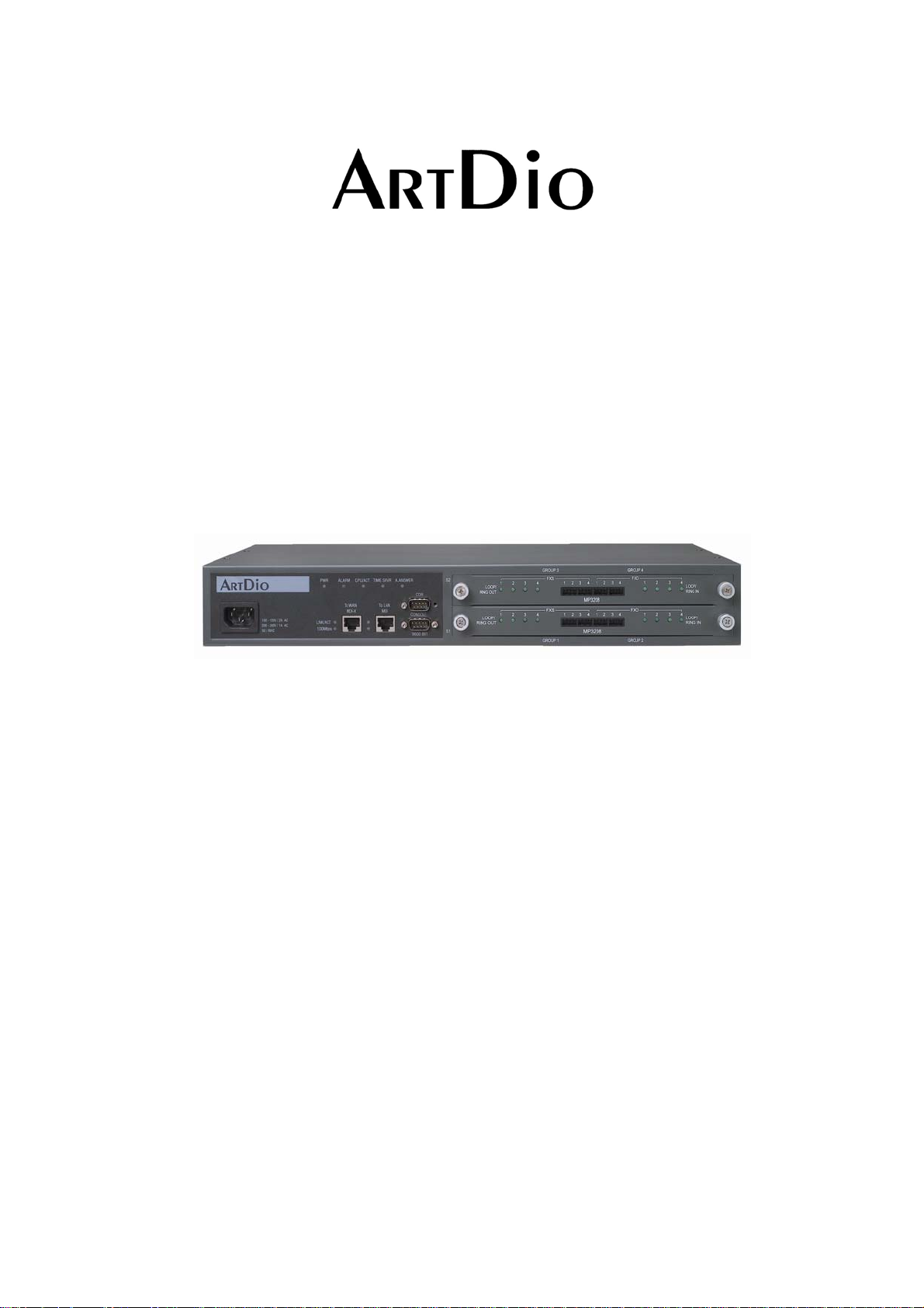
Voice Internet Phone Gateway
User Manual
IPC
version:1.0 update date:2003/12/21
A
RT
1000 Series
Dio Company Inc.
Page 2

ARTDio IPP 1000 Series
Safety Instructions
1. Do not attempt to service or repair the product. Any servicing or repair of this equipment should
be referred to qualified service technicians.
2. To avoid electric shock, do not put fingers, pins, wires, or objects of any sort into vents, or other
openings in the equipment.
3. To avoid accidental fire, or shock, do not twist the power cord, or place heavy items on it.
4. The equipment should be connected to a power supply of the type described in the user’s manual,
or as marked on the product.
5. Dispose of the product’s plastic packaging carefully in order to prevent hazards to children and
pets.
6. The in-coming telephone line should always be connected to the FXO jack, or interface. It shou ld
not be connected to the FXS jack or interface, as this will cause damage to the product.
7. Please read all the instructions before using this product.
Warning
1
Page 3

ARTDio IPP 1000 Series
Table of Contents
SAFETY INSTRUCTIONS ----------------------------------------------------------------------------------1
1. PREFACE--------------------------------------------------------------------------------------------------6
1-1 PBX Function:----------------------------------------------------------------------------------------------------------------- 6
1-2 ADDITIONAL IPP FEATURES--------------------------------------------------------------------------------------------- 7
2. PACKAGE CONTENTS --------------------------------------------------------------------------------8
3. PANEL FEATURES -------------------------------------------------------------------------------------9
3-1 FRONT PANEL----------------------------------------------------------------------------------------------------------------- 9
3-2 REAR PANEL------------------------------------------------------------------------------------------------------------------- 9
3-3 MODULES----------------------------------------------------------------------------------------------------------------------- 9
3-3.1 INDICATOR DESCRIPTION-------------------------------------------------------------------------------------------10
3-3.2 PORT DESCRIPTION ---------------------------------------------------------------------------------------------------10
4. BASIC INSTALLATION ------------------------------------------------------------------------------ 11
4-1 HARDWARE CONNECTIONS --------------------------------------------------------------------------------------------11
4-1.1 Connect Power and Telephone Lines -----------------------------------------------------------------------------------11
4-1.2 PC Connection-------------------------------------------------------------------------------------------------------------11
4-2 CONFIRMING and/or CHANGING REGION ID ---------------------------------------------------------------------12
4-2.1 HOW TO OBTAIN AN IP ADDRESS---------------------------------------------------------------------------------12
4-2.2 SETTING THE IP---------------------------------------------------------------------------------------------------------13
4-2.3 SETTING THE WEB PAGE PASSWORD----------------------------------------------------------------------------14
4-2.4 SETTING THE PHONE NUMBER------------------------------------------------------------------------------------14
5. SETTING FUNCTIONS-------------------------------------------------------------------------------16
5-1 Inter-System Calls -------------------------------------------------------------------------------------------------------------16
5-1.1 SETTING EXTENSION NUMBERS----------------------------------------------------------------------------------17
5-2
CALLING OUTSIDE LINES -------------------------------------------------------------------------------------------18
2
Page 4

5-2.1 Assigning Trunk Group Access Code-----------------------------------------------------------------------------------19
ARTDio IPP 1000 Series
5-2.2 Assigning In-Coming FXO line to a Trunk Group--------------------------------------------------------------------20
5-3 Call Transfer--------------------------------------------------------------------------------------------------------------------20
5-4 Call Pickup----------------------------------------------------------------------------------------------------------------------21
5-5 Call Forward -------------------------------------------------------------------------------------------------------------------22
5-6 Operator-------------------------------------------------------------------------------------------------------------------------23
5-7 Speed Dial-----------------------------------------------------------------------------------------------------------------------24
5-8
VoIP Calls Budget Control-----------------------------------------------------------------------------------------------26
5-9 Outbound Transit Calls-------------------------------------------------------------------------------------------------------27
5-10 Inbound Transit Calls -------------------------------------------------------------------------------------------------------29
5-11 INTER-CONNECTING WITH OTHER IPH/ IPE UNITS----------------------------------------------------------30
5-12 SYSTEM FUNCTION ------------------------------------------------------------------------------------------------------31
5-12.1 Auto Attendant (Built-in DISA) ---------------------------------------------------------------------------------------31
5-13 Numbering Plan--------------------------------------------------------------------------------------------------------------32
5-14 Barring Classes ---------------------------------------------------------------------------------------------------------------32
5-14.1 Create a Barring Class---------------------------------------------------------------------------------------------------33
5-14.2 Changing a Barring Class Attribute -----------------------------------------------------------------------------------34
5-14.3 Assign Barring to a Extension------------------------------------------------------------------------------------------34
5-15 CALLING RECORD SMDR ----------------------------------------------------------------------------------------------35
5-16 FAX OPERATION----------------------------------------------------------------------------------------------------------- 35
6. WEBPAGE EXPLANATION------------------------------------------------------------------------- 36
6-1 Basic------------------------------------------------------------------------------------------------------------------------------36
6-1.1 General --------------------------------------------------------------------------------------------------------------------- 37
6-1.2 Inbound Transit------------------------------------------------------------------------------------------------------------38
6-1.3 Outbound Transit --------------------------------------------------------------------------------------------------------39
6-1.4 Off-net Forward -----------------------------------------------------------------------------------------------------------40
6-1.5 Speed Dial------------------------------------------------------------------------------------------------------------------41
6-1.6 Barring Class---------------------------------------------------------------------------------------------------------------42
6-2 IP Settings -----------------------------------------------------------------------------------------------------------------------44
3
Page 5

6-3 Advanced------------------------------------------------------------------------------------------------------------------------46
ARTDio IPP 1000 Series
6-3.1 General --------------------------------------------------------------------------------------------------------------------- 46
6-3.2 Numbering Plan -----------------------------------------------------------------------------------------------------------47
6-3.3 Trunk Group--------------------------------------------------------------------------------------------------------------48
6-4 Channel--------------------------------------------------------------------------------------------------------------------------49
6-4.1 Summary -------------------------------------------------------------------------------------------------------------------49
6-4.2 Configuration-------------------------------------------------------------------------------------------------------------50
6-5 Phone Book ---------------------------------------------------------------------------------------------------------------------51
6-6 Access Code---------------------------------------------------------------------------------------------------------------------52
7. SPECIAL APPLICATIONS --------------------------------------------------------------------------54
7-1 Using NAT Via Private IP----------------------------------------------------------------------------------------------------54
7-1.1 Virtual Servers on the IP sharing device--------------------------------------------------------------------------------54
7-1.2 Tested IP Sharing Devices------------------------------------------------------------------------------------------------55
7-1.3 IP Sharing Devices Not Recommended --------------------------------------------------------------------------------56
7-2 Firewall--------------------------------------------------------------------------------------------------------------------------56
8. FILE MANAMEMENT--------------------------------------------------------------------------------- 57
8-1 File Type-------------------------------------------------------------------------------------------------------------------------57
8-1.1 File Update Using FTP ---------------------------------------------------------------------------------------------------57
9. NETWORK MANAGEMENT------------------------------------------------------------------------60
9-1 Use Of The System Console--------------------------------------------------------------------------------------------------60
9-1.1 System Command Summary---------------------------------------------------------------------------------------------60
9-2 Use Of The Web Management Page----------------------------------------------------------------------------------------61
9-3 Management Via telephone --------------------------------------------------------------------------------------------------61
9-3.1 Command Summary ------------------------------------------------------------------------------------------------------61
10. INTER-CONNECTION VIA IPN-------------------------------------------------------------------62
10-1 IPN Control Port -----------------------------------------------------------------------------------------------------------62
10-2 IPP Setting IPN IP---------------------------------------------------------------------------------------------------------63
10-3 IPP WEB PAGE------------------------------------------------------------------------------------------------------------64
11. SPECIFICATIONS------------------------------------------------------------------------------------65
4
Page 6

ARTDio IPP 1000 Series
12. APPENDIX ---------------------------------------------------------------------------------------------66
12-1 List of Region ID By Country----------------------------------------------------------------------------------------------66
5
Page 7

ARTDio IPP 1000 Series
1. PREFACE
IPP is the latest in communication technology, combing PBX and VoIP functions. The system
enables no cost telephone and fax communications for significant saving of operations costs. The
system is easy to install, reliable, and is capable of multiple applications.
1-1 PBX Function:
Extension to extension:
The IPP provides the same inter-office communications as an advanced PBX, accommodating
12 extensions, numbered 11-22. Internal extension calling is easy, just pick up the receiver,
listen for the dial tone, and dial the two digit extension number you wish to connect with.
Extensions to any IPP unit’s extension:
Calls can be placed from a IPP extension to extensions at other IPP units via the internet.
Simply dial the number of the remote IPP unit, and add the two digit extension you wish to
reach.
Extensions to any IPH/IPC unit’s FXS access port:
With the IPP you can also call direct to IPH/IPC units via the internet, by simply dialing those
units’ phone number.
Call Pick-up Function:
The IPP can designate any extension for call pick-up.
Call Transfer Function:
The unit can perform a number of call transfer functions:
‧ Forward to any local IPP unit’s extension
‧ Forward to any remote IPP unit’s extension
‧ Forward to any IPH/IPC unit’s FXS access port
Speed Dial Function :
The IPP unit has speed dialing with 100 settings, which are exempted from barring functions.
Built in DISA:
The IPP accommodates 4 outside lines simultaneously, and has 5 pre-recorded options with
prompts.
IPP Basic Functions:
The IPP offers numerous routing options for in-coming calls:
‧ Designate a local extension as operator
‧ Forward to another IPP unit extension, or access port
‧ Forward to IPH/IPC unit’s FXS access port
Trunk Group:
The IPP provides for two Trunk Groups, and all lines are easily assigned to one of the groups
as desired.
Barring Class:
All extensions can easily be assigned to one of 6 barring classes.
SMDR:
The IPP has SMDR call display based on an RS-232, which shows the number being called,
and length of call in real time. This can be recorded via PC for monitoring purposes.
6
Page 8

ARTDio IPP 1000 Series
1-2 ADDITIONAL IPP FEATURES
Transit-in Call for Remote Use:
When away from home or office, you may call into your IPP unit to connect with the IP
network.
Call Forward Feature:
Provides a follow-me service. You can receive calls via any IPP unit in the local area you are
in.
Support T.38 Fax Relay:
IPP provides fax over IP. Just as with voice communication, the unit can be configured to
transit a fax to any designated IPP unit around the world.
Support NAT:
The unit supports NAT allowing connections regardless of public or private IP being used.
Lifeline Support
IPP has a lifeline support feature ensuring users will always be able to place calls if there is a
power outage.
Remote System Management:
In addition to console based management, the system can be configured via internet, telephone,
or Telnet from any location.
:
FTP Remote Software Up-grade:
With properly coded up-grades, you may use FTP applications to up-grade software.
7
Page 9

2. PACKAGE CONTENTS
VoIP Gateway
AC power adapter with cable
Mounting rack
CD-ROM
8 IDC connectors
User’s Manual
ARTDio IPP 1000 Series
8
Page 10
ARTDio IPP 1000 Series
3. PANEL FEATURES
3-1 FRONT PANEL
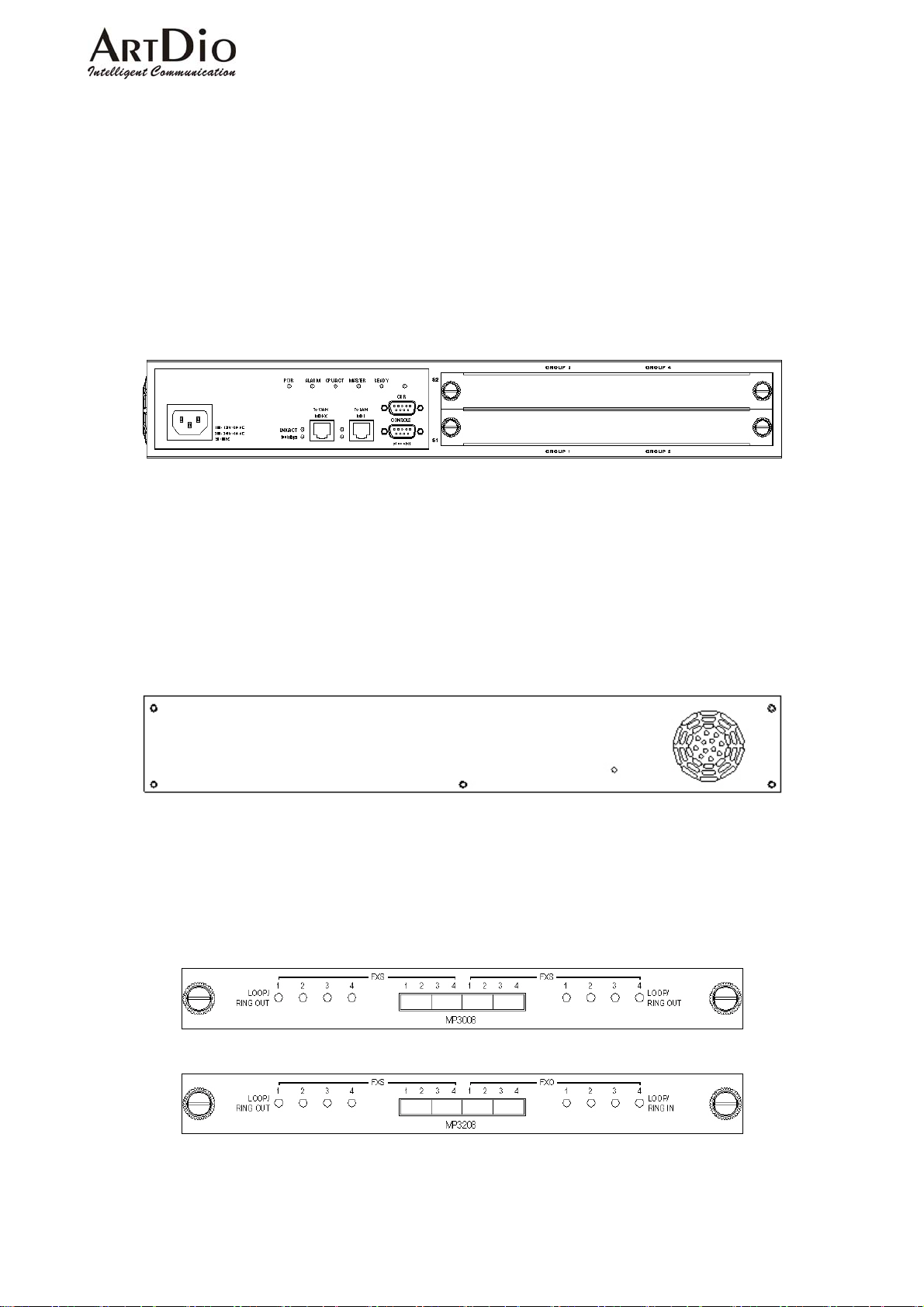
The IPP Series VoIP Gateway is a 19 inch modularized unit.
Each unit has 2 Ethernet ports, 1 console port, LED indicators, and, SMDR call recording port (for
comprehensive calling records).
Front Panel- 4FXO + 12 FXS ports
3-2 REAR PANEL
The IPP Series rear panel consists of only a fan vent, and re-set button (for service technician
use only)
3-3 MODULES
The IPP incorporates two modules:4 FXO + 4 FXS、8 FXS.
The front panels for these modules are shown below.
4 FXO + 4 FXS
8 FXS
9
Page 11
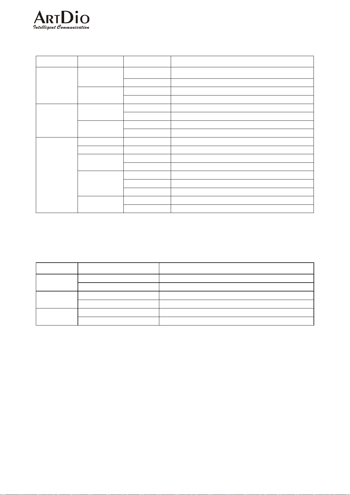
3-3.1 INDICATOR DESCRIPTION
LED Label Indication Description
ARTDio IPP 1000 Series
10/100
Ethernet
Port
Information
Device
On Link Up Link/ACT
Flash Sending/Receiving data Package
100Mbps
On 100Mbps
Off 10Mbps
On FXS off hook condition LOOP/ RING
OUT (FXS)
LOOP/ RING
IN (FXO)
Flash Sending
On FXO Receiving
Flash Ringing
PWR On Power supply normal
ALARM On Self test detects fault or FXO line cut-off
On CPU normal operation CPU/ACT
Flash Computer in use
On TIME SERVER On-line
TIME SRVR
Flash TIME SERVER Connecting
Off TIME SERVER Off-line
A.ANSWER
On Auto Answer Engaged
Off Auto Answer Disengaged
3-3.2 PORT DESCRIPTION
Port
RS-232
Label Description
FXS Connects to telephone or fax Voice
FXO Connects to line
To WAN RJ-45 Connects to internet Ethernet
To LAN RJ-45 Connects to local LAN
CDR SMDR call recording
CONSOLE Console
10
Page 12
4. BASIC INSTALLATION
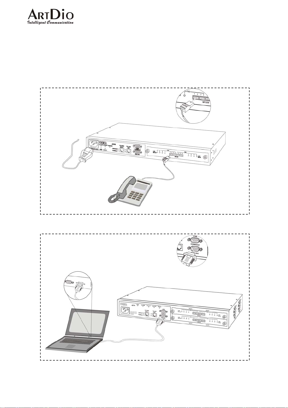
4-1 HARDWARE CONNECTIONS
4-1.1 Connect Power and Telephone Lines
ARTDio IPP 1000 Series
4-1.2 PC Connection
11
Page 13
ARTDio IPP 1000 Series
4-2 CONFIRMING and/or CHANGING REGION ID
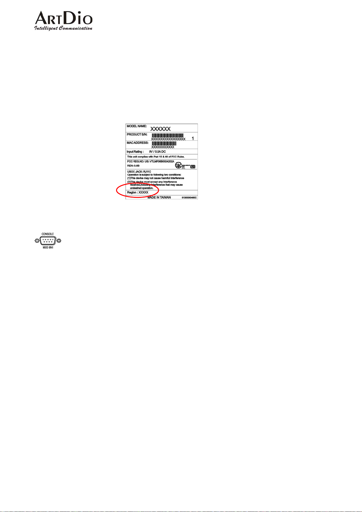
If you are installing your IPP unit in the default region, you may skip this procedure. The
default region is printed on a label on the shipping box (see example below).
If you are installing the unit in any region other than that specified on the label, you will need to
re-configure the IPP unit to the correct Region ID.
See the appendix for 12-1 List of Region ID By Country
To use the console, use the following procedure:
IPP>enable
IPP #configure
Enter configuration commands, one per line. End with CNTL/Z
IPP (config)#regional_id 07
IPP (config)#exit
IPP #delete nvram
This command resets the system with factory defaults.
All system parameters will revert to their default factory settings. All static
and dynamic addresses will be removed.
Reset system with factory defaults, [Y]es or [N]o? Yes
4-2.1 HOW TO OBTAIN AN IP ADDRESS
The IPP unit requires an IP address for operation. Before installation you need to determine
how to obtain an IP address from your local ISP. Static IP, DHCP, or PPPoE can all be used. The
following table helps you determine what information you will need. If your ISP offers static IP,
you may need to obtain an IP from MIS staff to prevent an IP conflict. Otherwise, DHCP (as
provided by most broadband cable), and PPPoE (provided by most ADSL broadband providers) will
work correctly.
12
Page 14
ARTDio IPP 1000 Series
IP Environment Required Information
Static IP
Public IP address
IP address
Subnet mask
Default Gateway
It is recommended that you obtain an IP address from
MIS staff in order to prevent an IP conflict.
Private IP address
IP address
Subnet mask
Default Gateway
It is recommended that you obtain an IP address from
MIS staff in order to prevent an IP conflict.
Note:Your private IP requires an IP sharing device, and
this device must be configured to treat the IPP unit, and
the IP it is using as a ‘virtual server’.
Dynamic IP Address (DHCP) DHCP Mode
PPPoE
Account Number
Password
This information is normally provided by your ISP . If
you don’t have this information, contact your ISP.
4-2.2 SETTING THE IP
The IP address can be set via the console, or the Web Management Page.
To use the console, use the following procedure:
IPP >enable
IPP #configure
Enter configuration commands, one per line. End with CNTL/Z
IPP (config)#ip state user
IPP (config)#ip address 210.62.149.250 255.255.255.128
System needs to restart
IPP (config)#ip default-gateway 210.62.149.254
IPP (config)#exit
IPP #restart
This command resets the system. System will restart operation code agent.
Reset system, [Y]es or [N]o? Yes
13
Page 15
ARTDio IPP 1000 Series
4-2.3 SETTING THE WEB PAGE PASSWORD
Before entering the WEB Management Page first set the password to prevent unauthorized use.
The password can be 1-6 letters or digits, for example ‘123’. The IPP series requires a password
otherwise the web management interface cannot be used.
Use the console to set the password:
IPP >enable
IPP #configure
Enter configuration commands, one per line. End with CNTL/Z
IPP (config)#password web_write password 123
IPP (config)#exit
4-2.4 SETTING THE PHONE NUMBER
The IPP can accommodate four in-coming lines, however, when setting the phone number,
only one number is required.
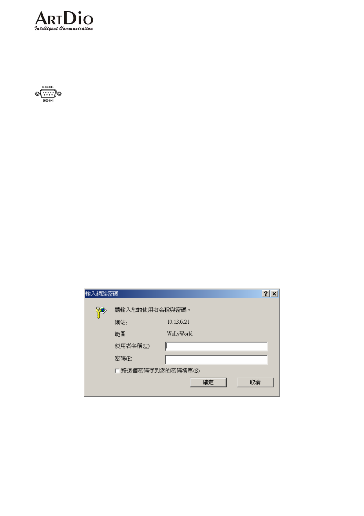
Go to the IPP website, by entering the IP address. You will see a page such as the example
below. Type in the user ID (default is WEB) and the password previously set, select Enter, and you
will access the web management page.
14
Page 16
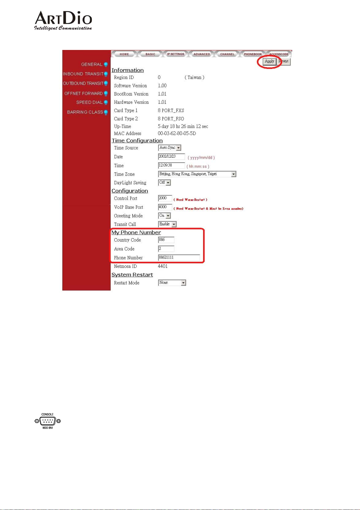
Setting phone number on web page:/ BASIC / My Phone Number
ARTDio IPP 1000 Series
In the field ‘My Phone Number’, will appear the country code corresponding to the entered
Region ID.
Country Code:Enter your country code in the “Country Code”
Area Code:Enter your area code in the Area Code field
Phone Number:Enter your local phone number in the Phone Number field
Click ‘Apply’ at the top right of the page.
Select ‘Warm Restart’ in the System Restart field drop-down box.
Click ‘Apply’.
To use the console, use the following procedure:
Does not support the feature.
15
Page 17
ARTDio IPP 1000 Series
5. SETTING FUNCTIONS
5-1 Inter-System Calls
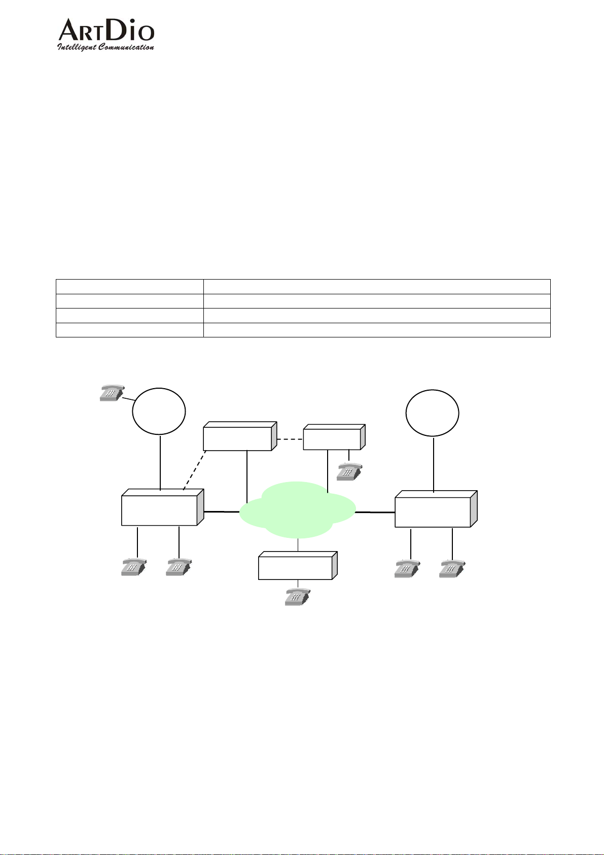
With the IPP Series, you can call other IPP units, and connect to the IPE system. To call an
extension on the same IPP unit simply dial the desired extension number (11-22)
See the table below for the dialing procedure to call to:
Another IPP unit
A IPH/IPC access port
A IPE access port via IPN
Dialing Method:
Receiver Dialing Procedure
Another IPP unit <IP Calls Access Code> + IPP + Phone + Ext. + “#”
IPH/IPC unit FXS port <IP Calls Access Code> + IPH/IPC + Phone + “#”
IPE FXS via IPN <IP Calls Access Code> + IPN ID + “#”
886-2-26951111
886-2-8226-8888
Taipei
x11
Carrier
IPP
…
x22
IPN
IP
886-2-2955-3368
IPH
IPN ID 111
IPE
x11
Carrier
1-644-1234567
IPP
USA
…
x22
16
Page 18
ARTDio IPP 1000 Series
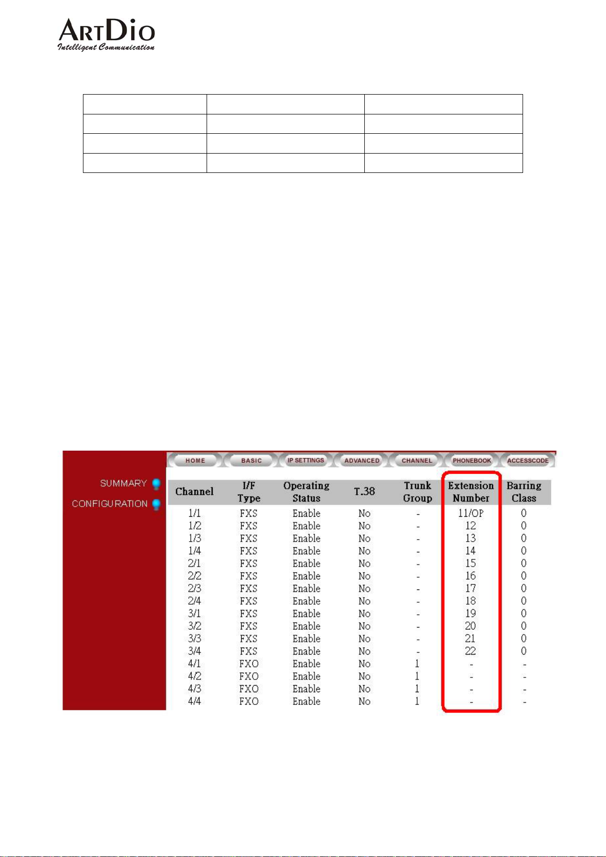
Parameters for example above
Setting Place: Taipei IPP Place: USA IPP
Telephone Number 886-2-8226-8888 1-644-1234567
Extension Number 11-22 11-22
IP Calls Access Code # #
Dialing Example (from Taipei IPP unit):
Taipei extension 11 calling Taipei extension 22:Extension 11 pick-up the receiver, dial 22
Taipei extension 11 calling USA extension 22:Extension 11 pick-up the receiver, dial
#1644123456722#
Dialing Example (from USA IPP unit):
U.S. extension 11 calling U.S. extension 22:Extension 11 pick-up the receiver, dial 22
U.S. extension 11 calling Taipei extension 22:Extension 11 pick-up the receiver, dial
#88628226888822#
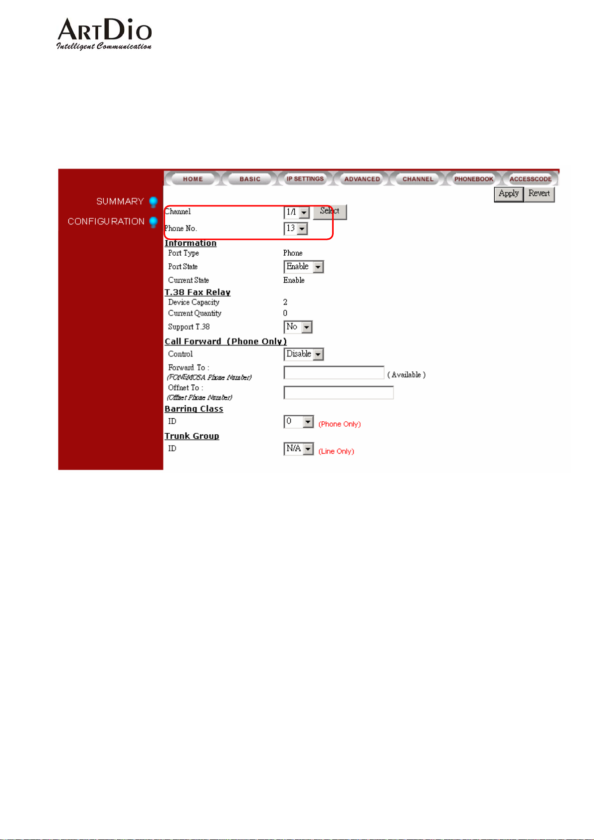
5-1.1 SETTING EXTENSION NUMBERS
To set extension numbers, select ‘CHANNEL’ on the Web Management Page. You will see a
summary of the current configuration.
17
Page 19
ARTDio IPP 1000 Series
Select CHANNEL\CONFIGURATION to bring up the following page:
1. Select Channel in the ‘Channel’ field drop-down box
2. Select extension number (11-22) in the ‘Phone Number’ field drop-down box
3. Click ‘Apply’
5-2 CALLING OUTSIDE LINES
Each FXO can be assigned to one of two trunk groups. All in-coming lines can be assigned to
one trunk, the other trunk being inactive. Any extension can work off either trunk group by dialing
the appropriate ‘Trunk Group Access Code’.
18
Page 20
ARTDio IPP 1000 Series
5-2.1 Assigning Trunk Group Access Code
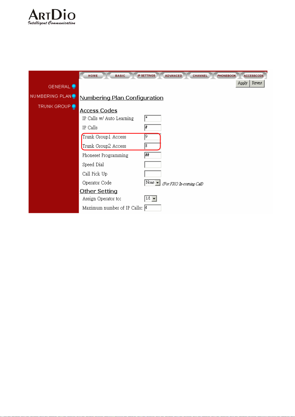
Select the ‘ADVANCED / NUMBERING PLAN’ icons on the Web Management page.
Assign the trunk group access codes in the fields:
Trunk Group1 Access
Trunk Group2 Access
In the example above the Access Code for Trunk Group 1 is ‘9’, and the Access Code for Trunk
Group 2 is ‘8’, for any extension.
19
Page 21
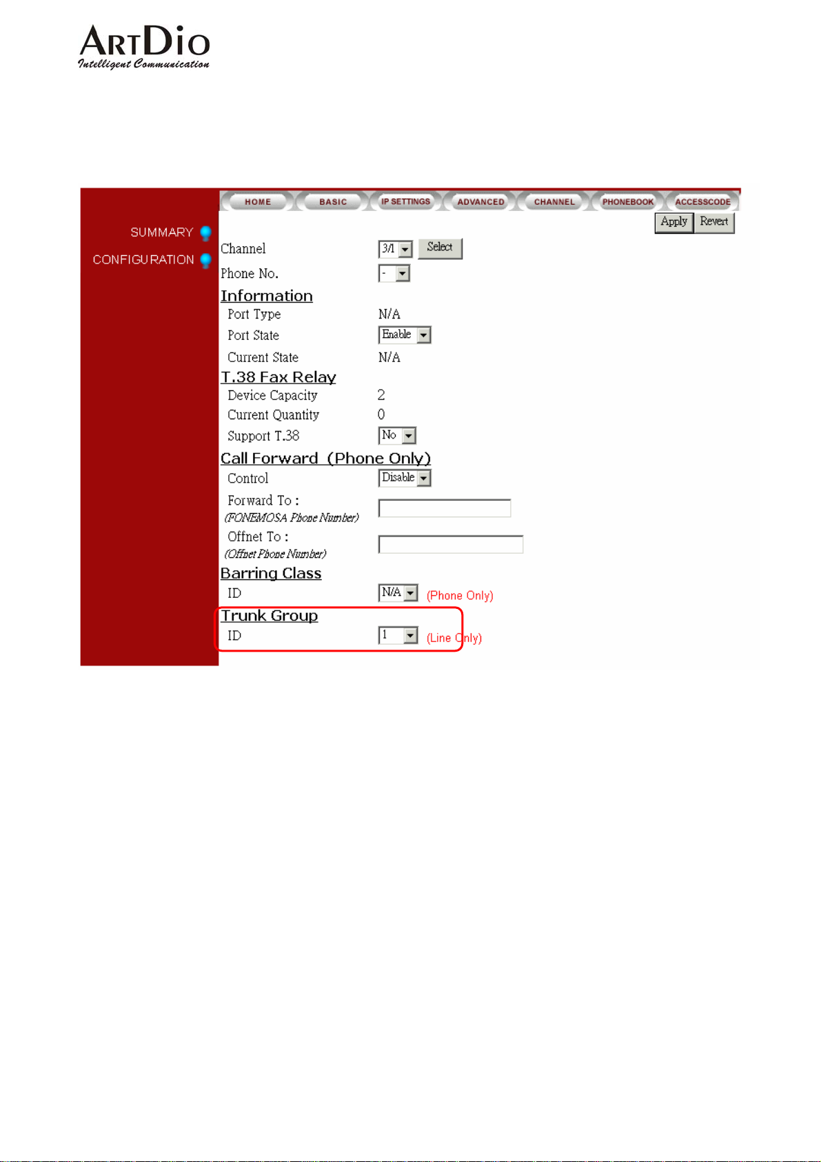
5-2.2 Assigning In-Coming FXO line to a Trunk Group
Select ‘CHANNEL \ CONFIGURATION ‘ on the Web Management Page
ARTDio IPP 1000 Series
Select Group 1 or 2 in the ‘Trunk Group ID’ field at the bottom of the page, Click ‘Apply’.
In the example below, Channel 3/1 has been assigning to Trunk Group 1.
5-3 Call Transfer
Any extension can transfer a call to:
Any extension on the local IPP unit
Any other IPP unit extension
Any IPH/IPC unit FXS access port
Any IPE FXS access port via IPN
20
Page 22
ARTDio IPP 1000 Series
Call Transfer Dialing Method
Destination Transfer Procedure Example
Internal Extension Flash button + extension 14
Another IPP Extension ‘*’ + IPP unit tel. number +
Extension + ‘#’
*8226336814#
(82263368 is IPP unit tel.
number,14 is Extension)
Any IPH/IPC unit ‘*’ + IPP unit tel. number + ‘#’ *82263368#
(82263368 is IPP unit tel. number)
Any IPE unit ‘*’ + IPE, IPN ID + ‘#’ *9823#
(9823 is IPN ID)
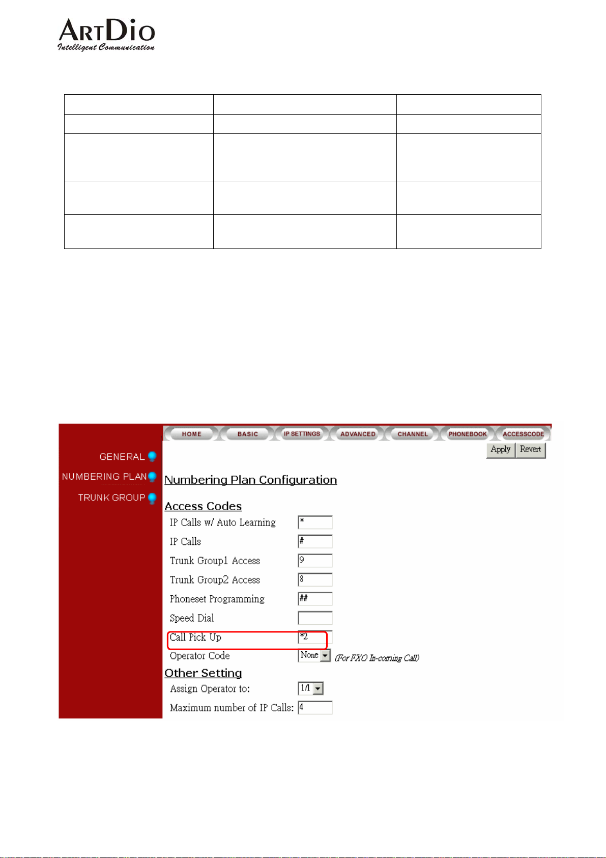
5-4 Call Pickup
Any extension can answer the ring of any other extension by dialing the ‘Call Pick Up’ access
code, which must be assigned.
Select ‘ADVANCED / NUMBERING PLAN’ on the Web Management Page
In the example above the ‘Call Pick Up’ access code is *2.
21
Page 23
5-5 Call Forward
Any IPP extension can forward a call to:
Any extension on the local IPP unit
Any other IPP extension
Any IPH/IPC unit FXS port
Any IPE FXS access port via IPN
Any Off-net Forward phone number
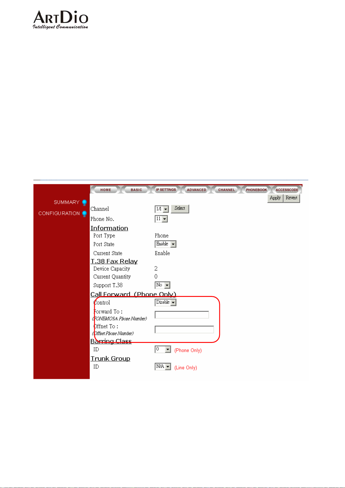
Setting Call Forwarding Destination.
Select ‘CHANNEL / CONFIGURATION’ on the Web Management Page
ARTDio IPP 1000 Series
In the ‘Call Forward (Phone Only)’ section:
Enter a IPP phone number in the ‘Forward to:
Enter a phone number in the ‘Offnet To:
Click ‘Apply’
(IPP Phone Number)
(Offnet Phone Number)
22
’ field
’ field
Page 24
ARTDio IPP 1000 Series
Dialing Procedures
Parameter Command
Control Select “Enable”
Forward T o:
Inter Office Extension #
Local IPP Ext. Local IPP phone number + Ext.
Any IPP unit Any IPP unit phone number + Ext.
Any IPP unit Any IPP phone number
Any IPE unit via IPN Any IPE unit access code number
Offnet To:
Any phone number in the Call
Enter the desired phone number in the field
Forward, ‘Offnet To’ field
5-6 Operator
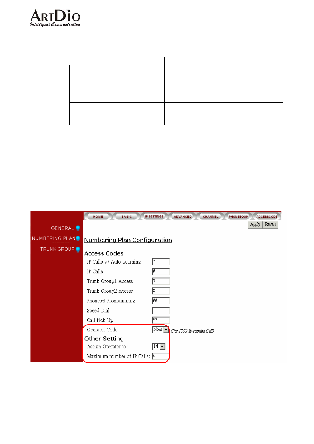
Setting the operator code
Select ‘ADVANCED \ NUMBERING PLAN’ on the Web Management Page
See the code in the ‘Operator Code’ field of the Access Codes section
Alternately in the ‘Other Setting’ section, enter an extension in the ‘Assign Operator to’
field
Click ‘Apply’
Operator Call Forward
The ‘OPERATOR’ function of the IPP will forward calls to:
Any internal extension
Any IPP unit extension
Any IPE unit via IPN
Any phone number
23
Page 25
ARTDio IPP 1000 Series
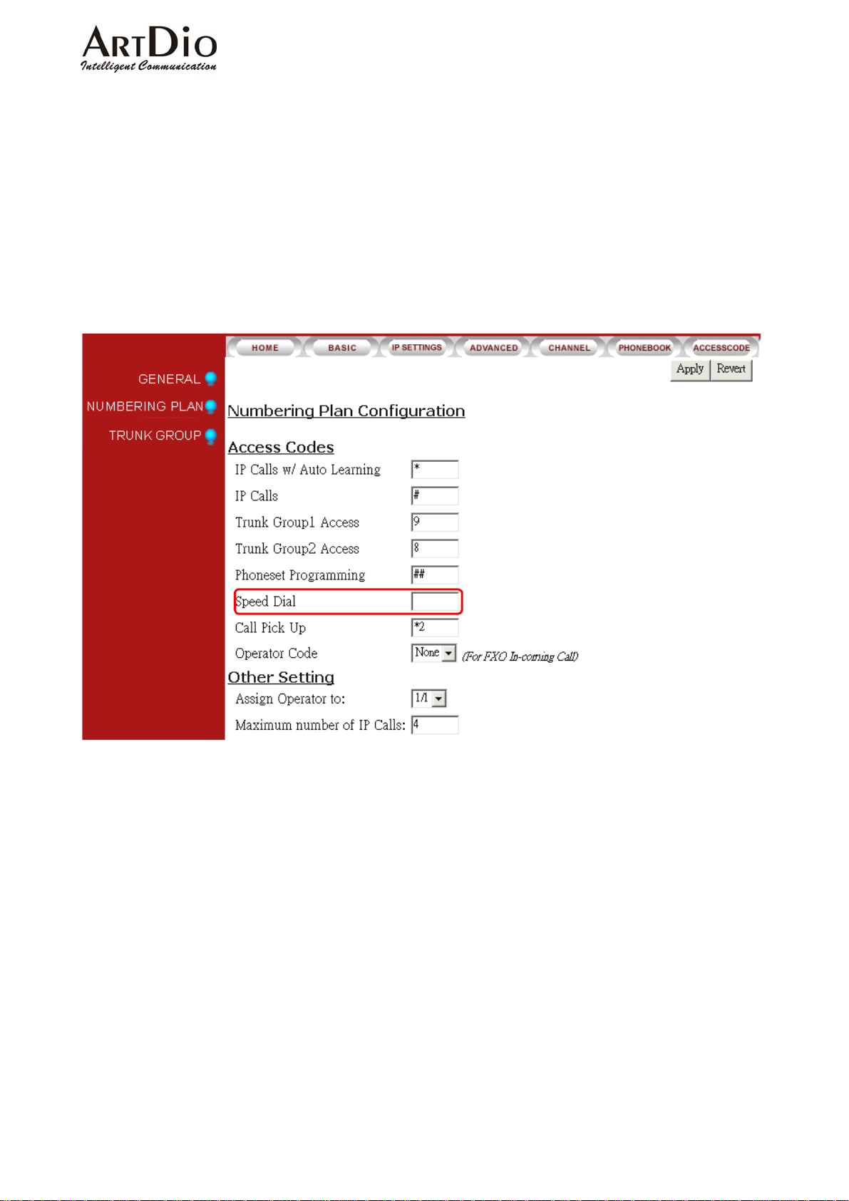
5-7 Speed Dial
The IPP series has a speed dial memory capacity of 100 phone numbers. The phone number
can be set from any extension.
Setting the speed dial access code:
Select ‘ADVANCED \ NUMBERING PLAN’ on the Web Management Page.
In the access code section enter a speed dial access code (0-99) in the ‘Speed Dial’ field.
Click ‘Apply’
24
Page 26
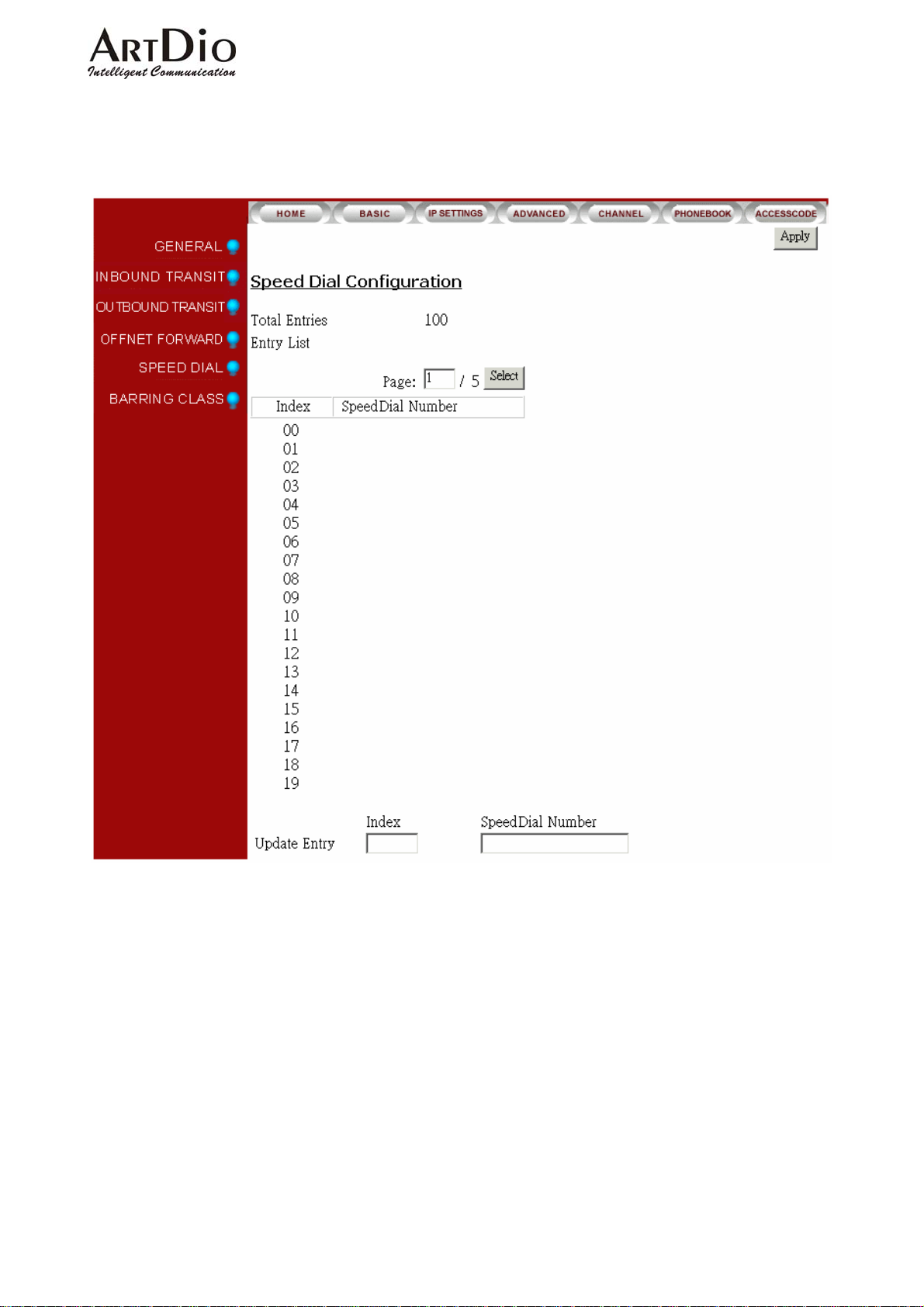
Setting the speed dial phone number:
Select ‘BASIC \ SPEED DIAL’ on the Web Management Page
ARTDio IPP 1000 Series
Enter the desired number(s) in the ‘Index’ field
Click ‘Apply’
25
Page 27
ARTDio IPP 1000 Series
5-8 VoIP Calls Budget Control
IPP series units operate under the G.729AB protocol with voice packets of 40ms with each
voice line using a bandwidth of 12K bps. Thus with the full capacity of IPP series’ 12 lines, the
requirement would be 144 bps (for voice only, not including any other data flow). Therefore the
VoIP volume must be limited to accommodate your system’s bandwidth.
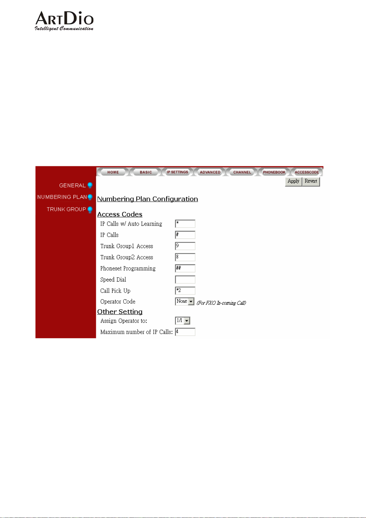
Setting the VoIP Calls Limit:
Select ‘ADVANCED \ NUMBERING PLAN’ on the Web Management Page
In the Access Codes section, enter the IP call limit in the ‘IP Calls’ field.
Click ‘Apply’
26
Page 28
ARTDio IPP 1000 Series
5-9 Outbound Transit Calls
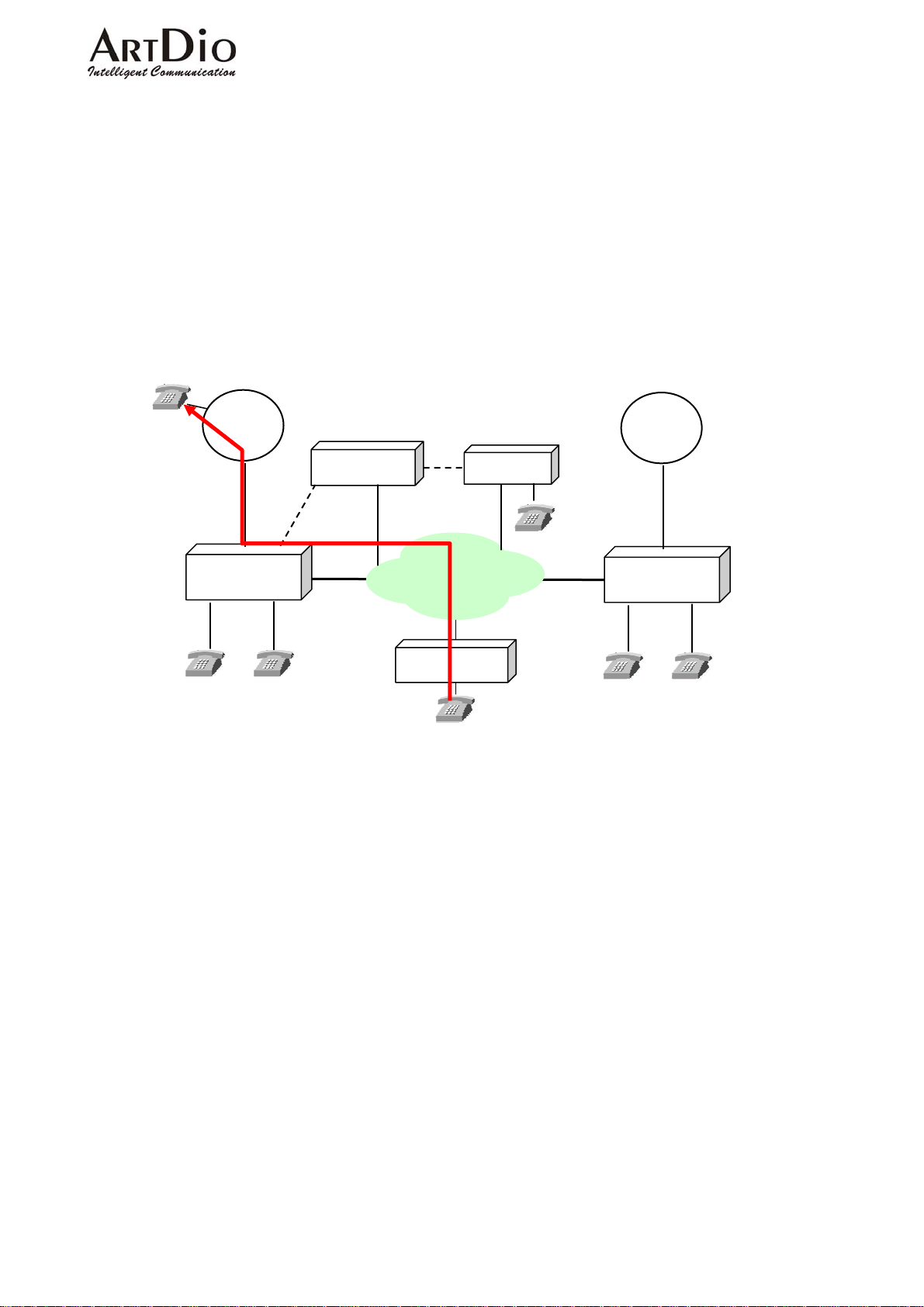
The IPP series is capable of forwarding calls from IPH/IPC/IPE series units to local PSTN. As
the transferring unit must pay for all local charges, the sending unit must be listed in the
‘Permission List Of Outbound Transit’.
In the following example we see the routing of an Outbound Transit call originating in U.S., and
being transited through s IPH unit in Taipei. (EX:#00886226951111#)
886-2-8226-8888
Setting the ‘Permission List Of Outbound Transit’
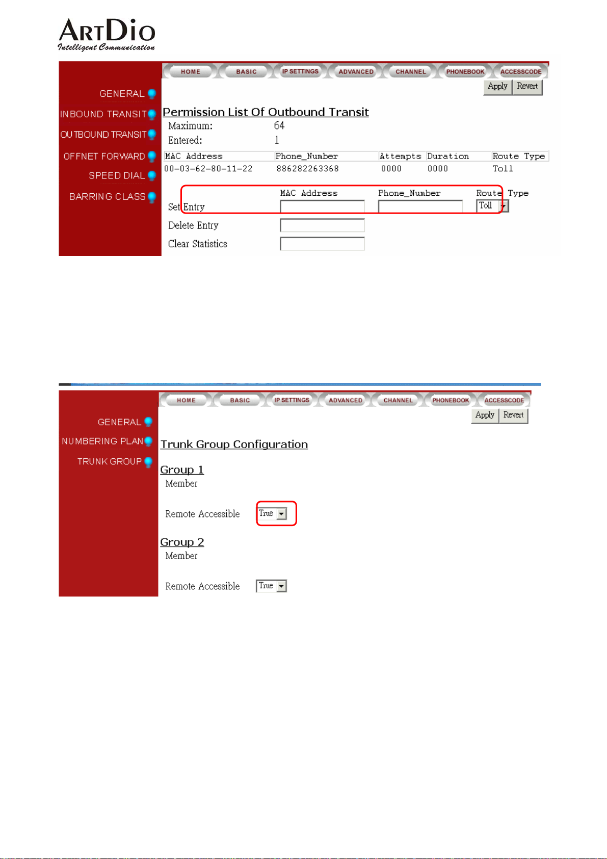
1) Select ‘BASIC \ OUTBOUND TRANSIT’ on the Web Management Page
2)
3)
4)
886-2-26951111
CO
IPN
IPN ID 111
IPE
CO
1-111-1234567
Taipei
x11
IPP
…
x22
IP
IPH
BJ
x11
IPP
…
x22
8610-2955-3368
In the MAC Address field set the remote unit(s) ‘MAC Address’ and ‘Phone Number’
In the Route Type field drop-down box select either ‘Toll’ or ‘Local’
Click ‘Apply’
U.S.
27
Page 29
5)
Select ‘ ADVANCED \ TRUNK GROUP’ on the Web Management Page
6)
In the ‘Remote Access’ field drop-down box select ‘True’
Click ‘Apply’
7)
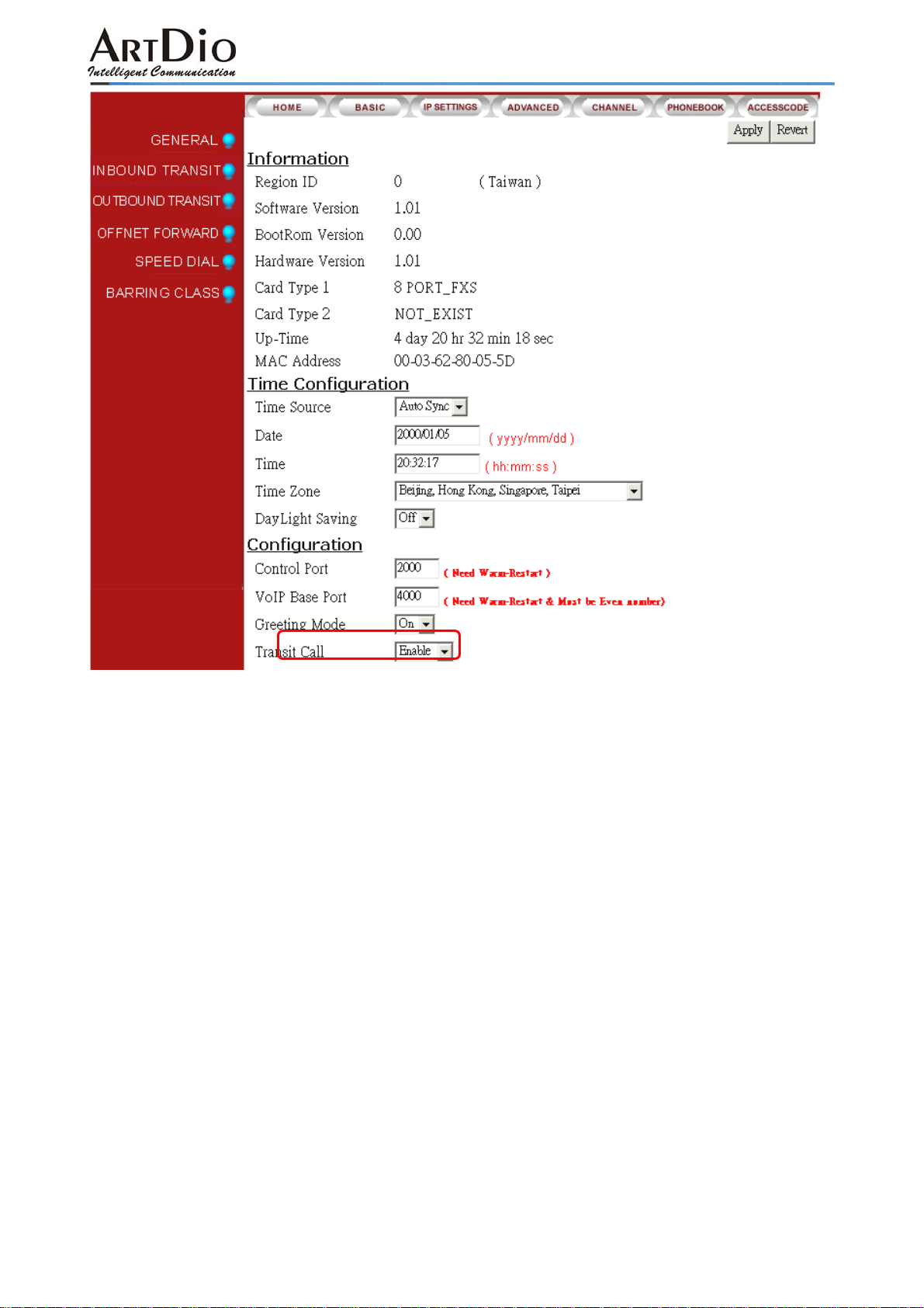
8) Select ‘BASIC \ GENERAL’ on the Web Management Page
ARTDio IPP 1000 Series
9)
In the ‘Configuration’ section select ‘Enable’ in the ‘Transit Call’ field drop-down box
28
Page 30
ARTDio IPP 1000 Series
10) Click ‘Apply’
5-10 Inbound Transit Calls
Incoming calls to IPP unit can be transferred to IPH/IPC/IPE, and IPP unit FXS ports.
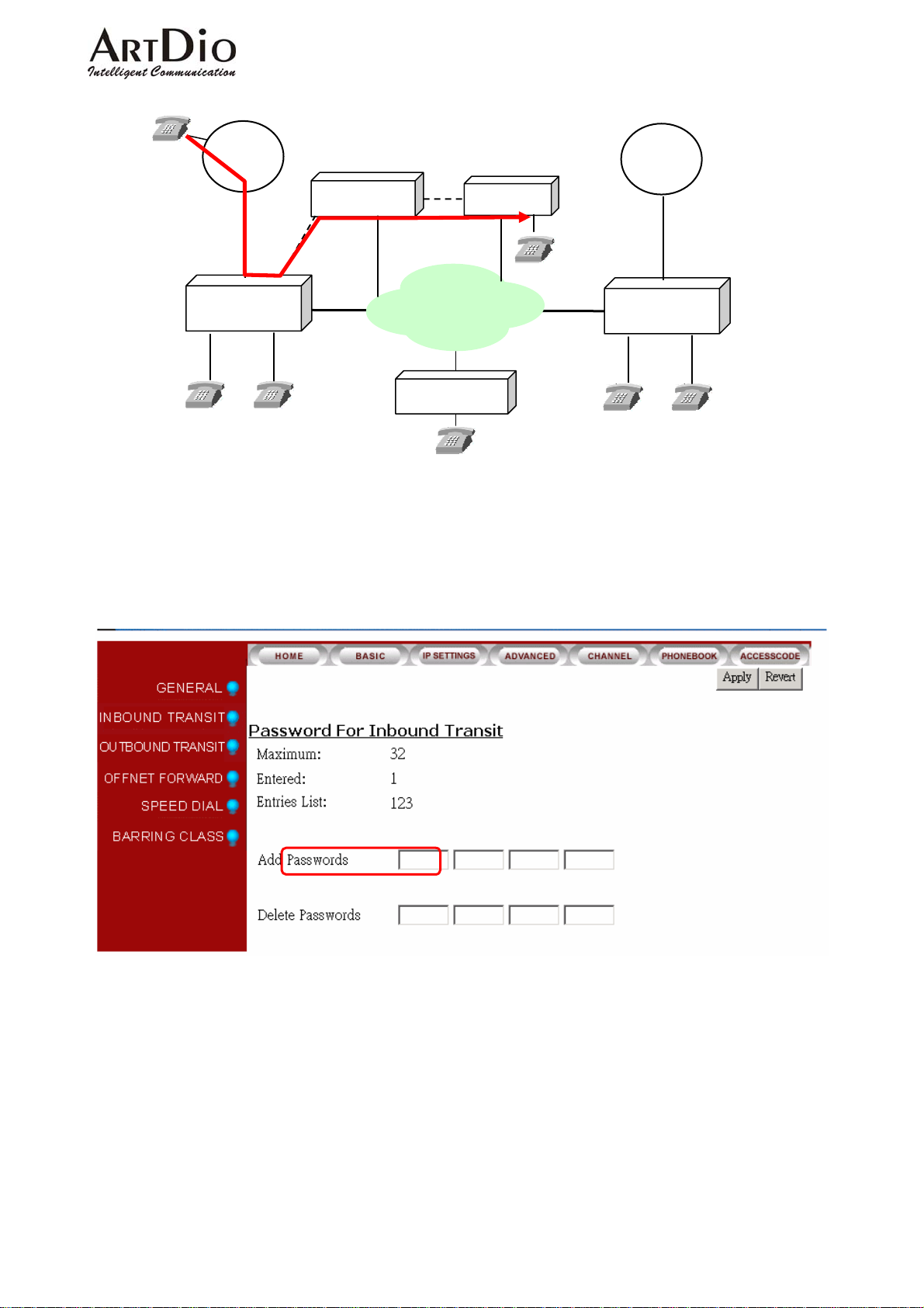
In the following diagram, a IPP receives, and transfers an in-coming call to IPE. The outside caller
dials the IPP unit’s phone number, and when he hears the greeting dial, # + inbound transit
password + #111# (111 being the IP N ID for IPE).
29
Page 31
886-2-26951111
ARTDio IPP 1000 Series
Carrier
IPN
IPN ID 111
IPE
886-2-8226-8888
Taipei
x11
IPP
…
x22
IP
IPH
x11 x22
886-2-2955-3368
Setting the Inbound Transit Password:
1) Select ‘BASIC \ INBOUND TRANSIT’ on the Web Management Page
2)
Enter password (up to 8 digits) in the ‘Add Password’ field
3)
Click ‘Apply’
Carrier
1-111-1234567
IPP
U.S.
…
5-11 INTER-CONNECTING WITH OTHER IPH/ IPE UNITS
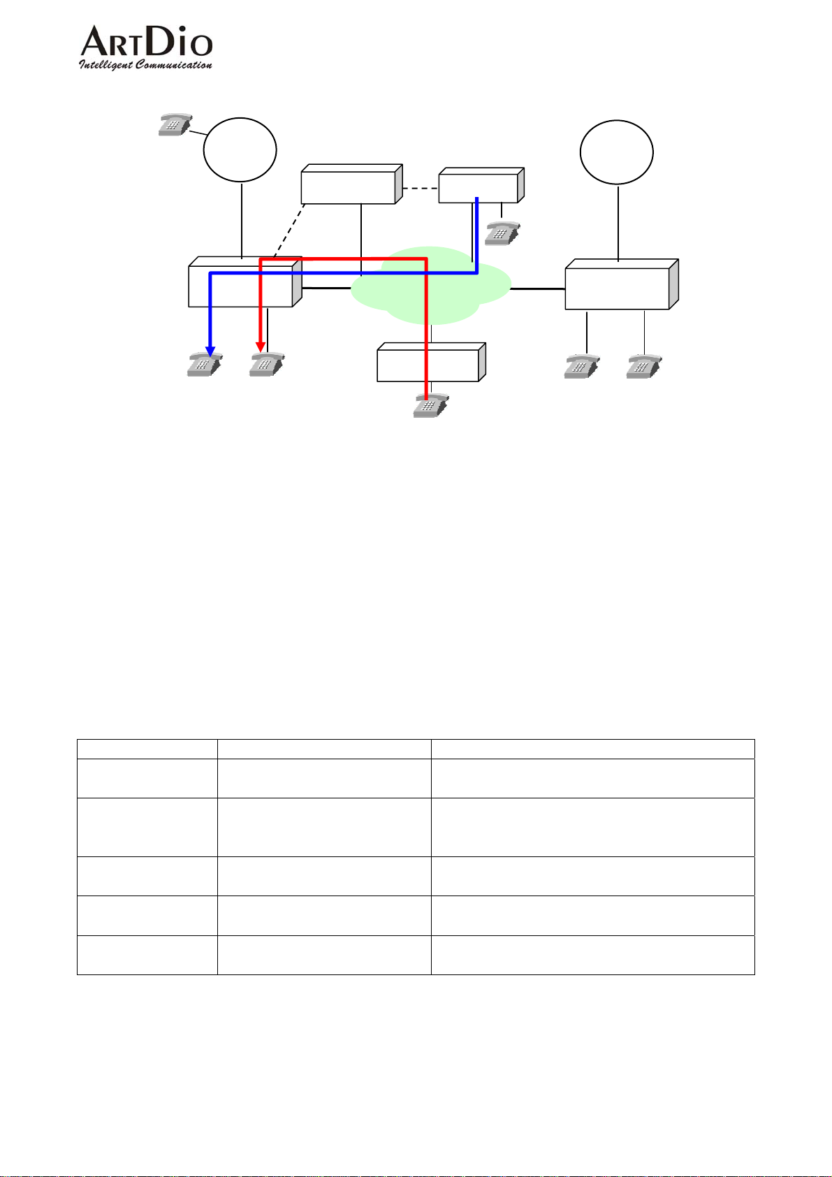
IPH / IPC series and IPE units can transfer calls directly to any extension of IPP units.
The example diagram below illustrates:
1、A IPH in BJ calls Ext. 22 of a IPP in Taipei, by dialing:#00 886 2 8226 8888 22#
2、A IPE unit calls Ext. 11 of a IPP unit in Taipei, by dialing:#1 00 886 2 8226 8888 11#。(#1 is the
IPE access code to IPP units).
30
Page 32
886-2-26951111
ARTDio IPP 1000 Series
Carrier
IPN
886-2-8226-8888
IPP
Taipei
…
x11 x22
5-12 SYSTEM FUNCTION
IPN ID 111
IPE
IP
IPH
8610-2955-3368
BJ
x11
Carrier
1-644-1234567
IPP
U.S.
…
x22
5-12.1 Auto Attendant (Built-in DISA)
The IPP series has an auto-attendant function to receive in-coming FXO calls. This function
does not engage in-coming IPP and IPE IP calls.
Programming the Auto- Attendant:
The unit is programmed for 5 different greetings of up to 1 minute each. No special tools are
required.
The recordings can be made from any extension, and the greeting file can be up-dated with FTP.
Greeting Function Content
Greeting (1) During office hours Welcome to ABC Co, please dial an extension
number, or 9 for operator assistance
Greeting (2) Extension is busy The extension you have dialed is engaged.
Please dial another extension, or 9 for operator
assistance
Greeting (3) Incorrectly dialed number We are not able to connect you with that
extension. Please re-dial.
Greeting (4) All extensions are busy All extensions are busy, please wait for your
connection. Thank you.
Greeting (5) After office hours It is after office hours. Please dial an extension,
or call again during office hours.
Enable the greeting for during or after office hours.
1) Enable the greeting for during office hours: Pick up the phone and dial ##9999 then dial 931#
2) Enable the greeting for during after office hours: Pick up the phone and dial ##9999 then dial
930#
31
Page 33

ARTDio IPP 1000 Series
Auto-Attendant Recording Commands
1. Pick up the phone, listen for dial tone, dial ##9999 after hearing confirmation response of two
beeps:
2. Record greeting 1, dial 991* Æ begin recording, dial # Æ when recording is finished
3. Save greeting 1 recording, dial 9# Æ dial # after hearing confirmation response of two beeps
4. Record greeting 2, dial 992* Æ begin recording, dial # Æ when recording is finished
5. Save greeting 2 recording, dial 9# Æ dial # after hearing confirmation response of two beeps
6. Record greeting 3, dial 993* Æ begin recording, dial # Æ when recording is finished
7. Save greeting 3 recording, dial 9# Æ dial # after hearing confirmation response of two beeps
8. Record greeting 4, dial 994* Æ begin recording, dial # Æ when recording is finished
9. Save greeting 4 recording, dial 9# Æ dial # after hearing confirmation response of two beeps
10. Record greeting 5, dial 995* Æ begin recording, dial # Æ when recording is finished
11. Save greeting 5 recording, dial 9# Æ dial # after hearing confirmation response of two beeps
5-13 Numbering Plan
NO TWO ACCESS CODES CAN HAVE IDENTI CAL DIGITS! Please regard this
requirement when setting access codes. It is recommended to review set access codes when setting
or re-setting a code to avoid a conflict or malfunction.
5-14 Barring Classes
A barring class is used to specify which numbers can or cannot be dialed. Every barring class
element includes the following information: There are six barring classes on the device and all
extensions can be assigned to any class. Initially they are all unassigned and have no association
with any gateways in the group.
Class Name
The name of class
Class Attribute
The class attribute can be set to either “Deny” or “Accept”. Both attributes have a barring table
and an exception table. Each class contains only one attribute.
Attribute Meaning
DENY
Denies
all numbers except those specified in the
Barring table:
Exception table:
ACCEPT
Barring table:
Exception table:
exception table. The barring table does not need to have
elements because “Deny” in general is used to bar all
numbers except those found in the exception table.
Accepts
all numbers except the numbers listed in the
barring table. However the numbers specified in the
exception table should not be barred.
32
Page 34

ARTDio IPP 1000 Series
5-14.1 Create a Barring Class
1. Select a barring class in the Class Entry in the ‘Class Information’ field and click the “Select”
button.
2. Assign a name for the class: enter the name in the ‘Class Name’ field and click the ‘Add
Name’ button.
3. Add an attribute to the class. You can select either Deny or Accept and click the ‘A dd Attr’
button.
4. At this point, you have successfully selected a barring class and have assigned it an attribute.
You can now assign barring numbers or exception numbers to this attribute using the ‘Add
Barr’ control or ‘Add Excp’ control.
5. After the barring class has been created, you must define which gateways this particular
barring class, applies to.
Examples
Example 1:
Assuming the device is located in Shanghai, the setting shown below only allow calls to Beijing and
cell phones. It denies all except 010 and 013 numbers.
Attribute DENY:
Barring Table:
Exception Table:
010
013
Example 2:
Assuming the device is located in Shanghai, the setting shown below only allows local calls. Long
distance (0) or international (00) calls would not be allowed.
However, Beijing (10) and Shenzhen (755) are allowed as they are included in the exception table.
Attribute ACCEPT:
Barring Table:
00
0
Exception Table:
010
0755
Example 3:
Assuming the device is located in San Jose (USA), the setting shown below only allows local calls.
Long distance (1) or international (001) calls would not be allowed.
However, Beijing (0018610) is allowed as it is included in the exception table.
Attribute ACCEPT:
Barring Table:
001
1
Exception Table:
0018610
33
Page 35
ARTDio IPP 1000 Series
Example 4:
Assuming the device is located in Tokyo (Japan), the setting shown below only allows local calls.
Long distance (0) or international (001) calls would not be allowed..
However, Shanghai (China) is allowed as it is included in the exception table.
Attribute ACCEPT:
Barring Table:
001
0
Exception Table:
0018621
5-14.2 Changing a Barring Class Attribute
Once an attribute has been assigned to a selected barring class, you will not be able to assign a
new attribute (New Attr) to that particular barring class. You must delete the old attribute (Delete
Attr) from the selected barring class before assigning a new attribute.
5-14.3 Assign Barring to a Extension
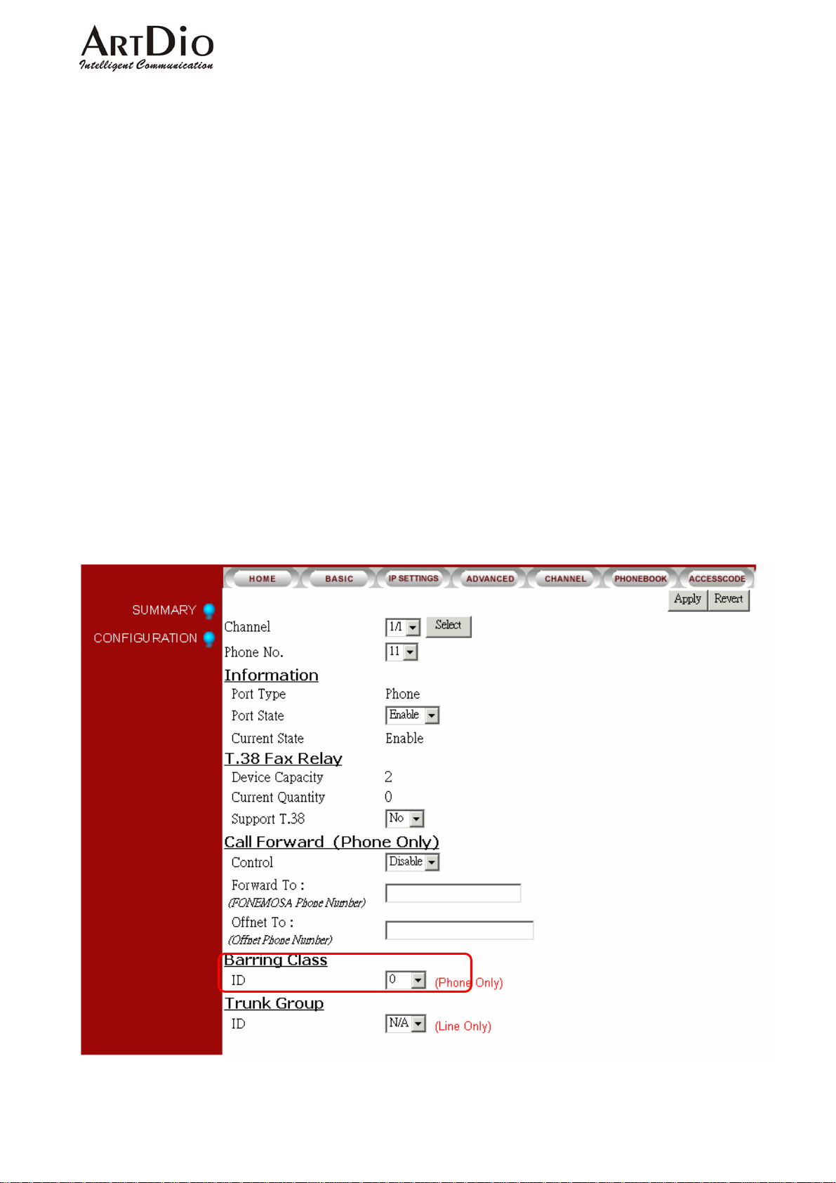
Select ‘CHANNEL\CONFIGURATION’ on the Web Management Page.
Select Class in the ‘Barring Class ID’ field at the bottom of the page, Click ‘Apply’.
34
Page 36
ARTDio IPP 1000 Series
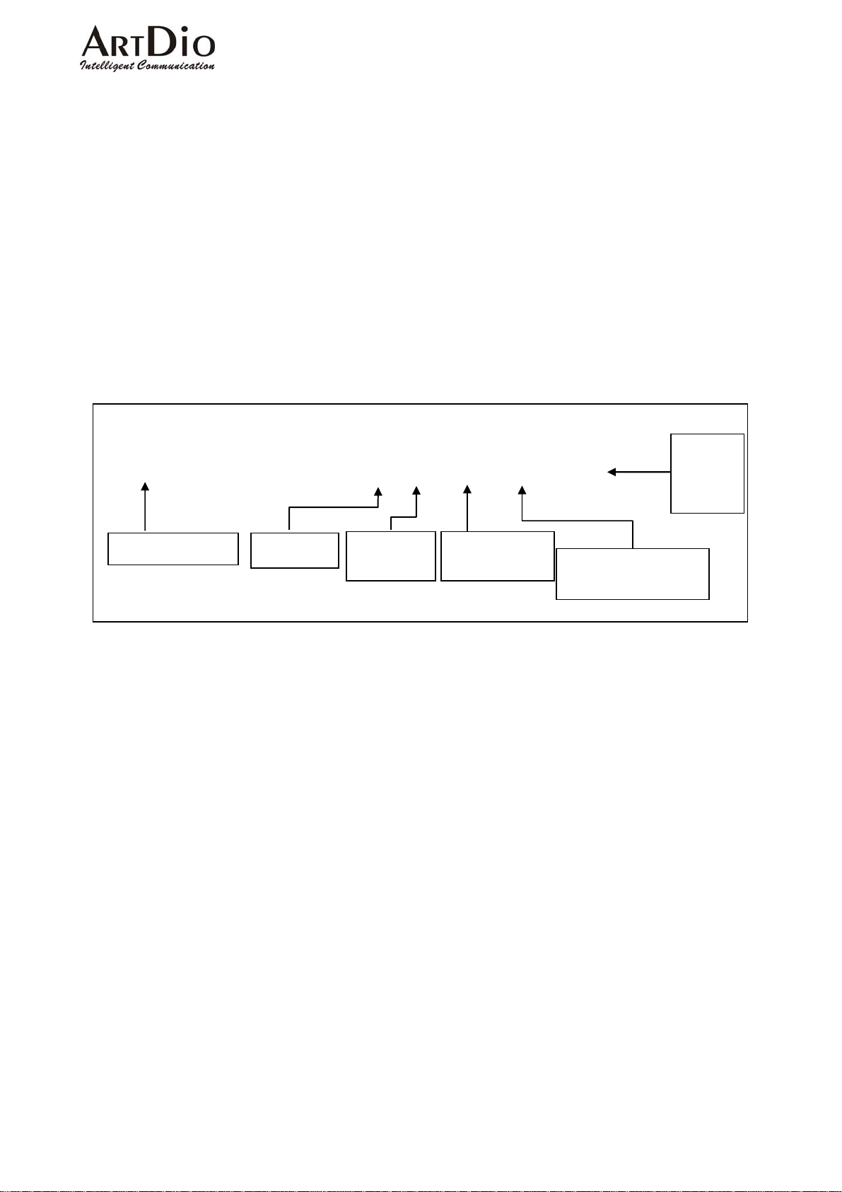
5-15 CALLING RECORD SMDR
All calls through the IPP series units via FXO ports will automatically generate a call detail
record, as seen in the example above. With additional software this record can be saved for purposes
such as billing as it details the number called, and the time of connection. The function can also be
used in real time to check if an incorrect number has been dialed.
NOTE:The SMDR function within the IPP unit is in real time, therefore if the additional required
software is not installed on the PC, no record will be saved, and the display will be terminated when
the call is disconnected.
SMDR as shown on PC screen
82263368 16 00:36:51 00:00:14 2 88624202
0921856869 15 00:37:55 00:00:04 2 88624202
29521133 14 00:36:51 00:00:14 1 88624202
Calling
Unit
Phone
Number
Number Called Channel
Time of
connection
Time of
Disconnection
1) Local
2) Long Distance
5-16 FAX OPERATION
All IPP series units utilize T.38 protocol compatible with fax machines. It should be noted,
however that only two fax machines functioning simultaneously, can be accommodated.
FAX Configuration
1) Select ‘CHANNEL \ CONFIGURATION’ on the Web Management Page
2) In the T.38 FAX Relay section, select ‘Yes’ in the ‘Support T.38’ field drop-down box
3) Click ‘Apply’
35
Page 37
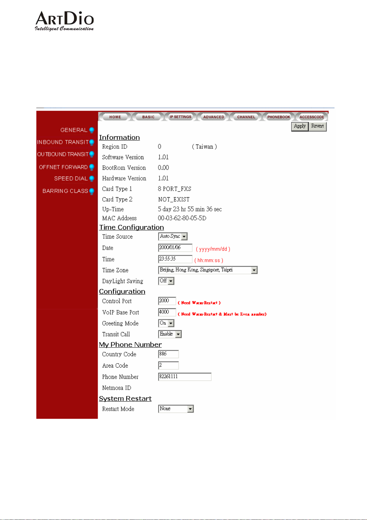
6. WEBPAGE EXPLANATION
6-1 Basic
ARTDio IPP 1000 Series
36
Page 38
ARTDio IPP 1000 Series
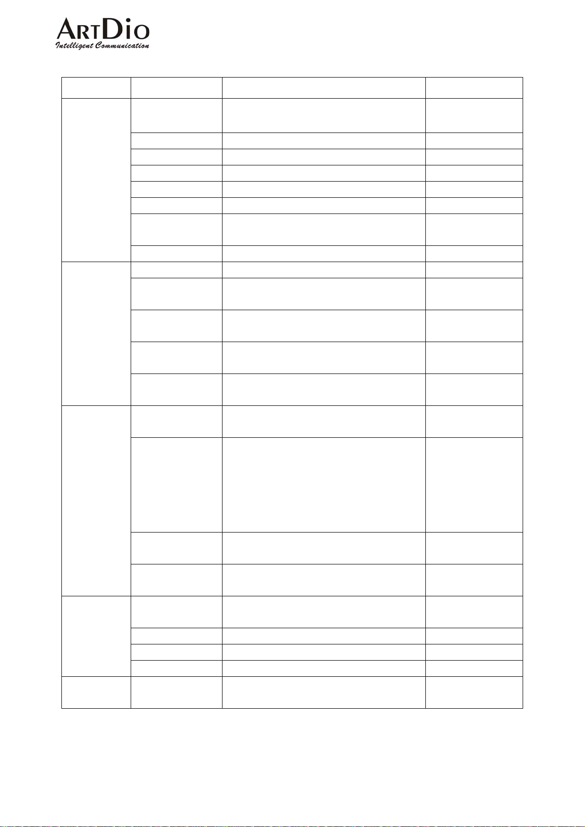
6-1.1 General
Section Item Field Description Default
Information
Time
Configuration
Configuration
My Phone
Number
System Restart Restart Mode Select the system restart mode
Region ID Refers to the country in which the
unit is operating
Software Version Displays the software version (Read Only)
BootRom Version Displays the BootRom version (Read Only)
Hardware Version Displays the Hardware version (Read Only)
Card Type 1 Displays the type of card 1 (Read Only)
Card Type 2 Displays the type of card 2 (Read Only)
Up-Time Indicates time the unit has been
running since connection
MAC Address Indicates the MAC address (Read Only)
Time Source Select ‘AutoSync’ or Manual ‘AutoSync’
Date With the time source field set to ‘Manual’, set the
date:yyyy/mm/dd.
Time With the time source field set to ‘Manual’, set the
time:hh/mm/ss.
Time Zone Select the city the unit is in from the ‘Time Zone’
field drop-down box.
Day Light Saving Select ’On’ or ‘Off’ in the ‘Day Light Saving’ field
drop-down box.
Control Port Control the IP connection signal, set the code in
the field (0 – 65535). (Requires Warm-Restart)
VoIP Base Port
Greeting Mode Select ‘On’ or ‘Off’ in the ‘Greeting Mode’ field
Transit Call Select ‘Enable’ or ‘Disable’ in the ’ Transit Call’
Country Code Set the country code of the country the unit is
Area Code Enter the local area code. None
Phone Number Enter the Phone Number of IPP unit None
IPN ID IPN ID (Read Only)
Control the VoIP connection signal, set the code in
the field (0 – 65534).
Note:
1) all numbers must be even
2) the warm-restart must be engaged to change
the code
drop-down box.
field drop-down box
operating in.
‘None’ /’ Cold Restart’ / ‘Warm Restart’.
(Read Only)
(Read Only)
None
None
OFF
2000
4000
ON
Enable
The Region ID will set
the code
None
None
37
Page 39
ARTDio IPP 1000 Series
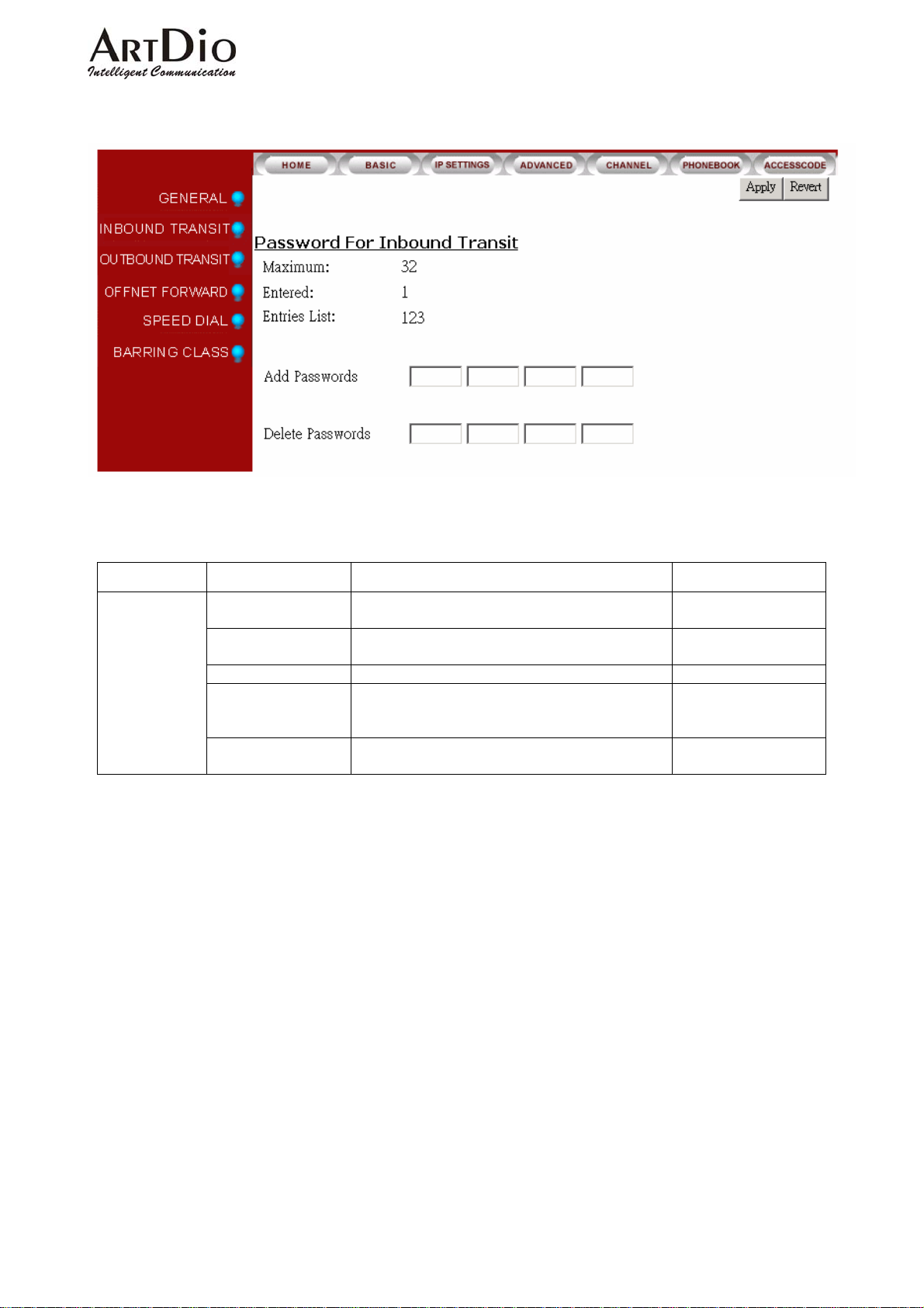
6-1.2 Inbound Transit
Section Item Field Description Default
Password For
Inbound Transit
Maximum Maximum number of entries
allowed.
Entered Number of entries of password
entered.
Entries List List of entries. (Read Only) None
Add Passwords Add passwords. A maximum of four sets of
passwords can be entered at the same time.
Passwords must be 1-8 digits.
Delete Passwords Delete password. Maximum four sets of password
can be deleted at the same time.
(Read Only) 32
(Read Only) 0
None
None
38
Page 40
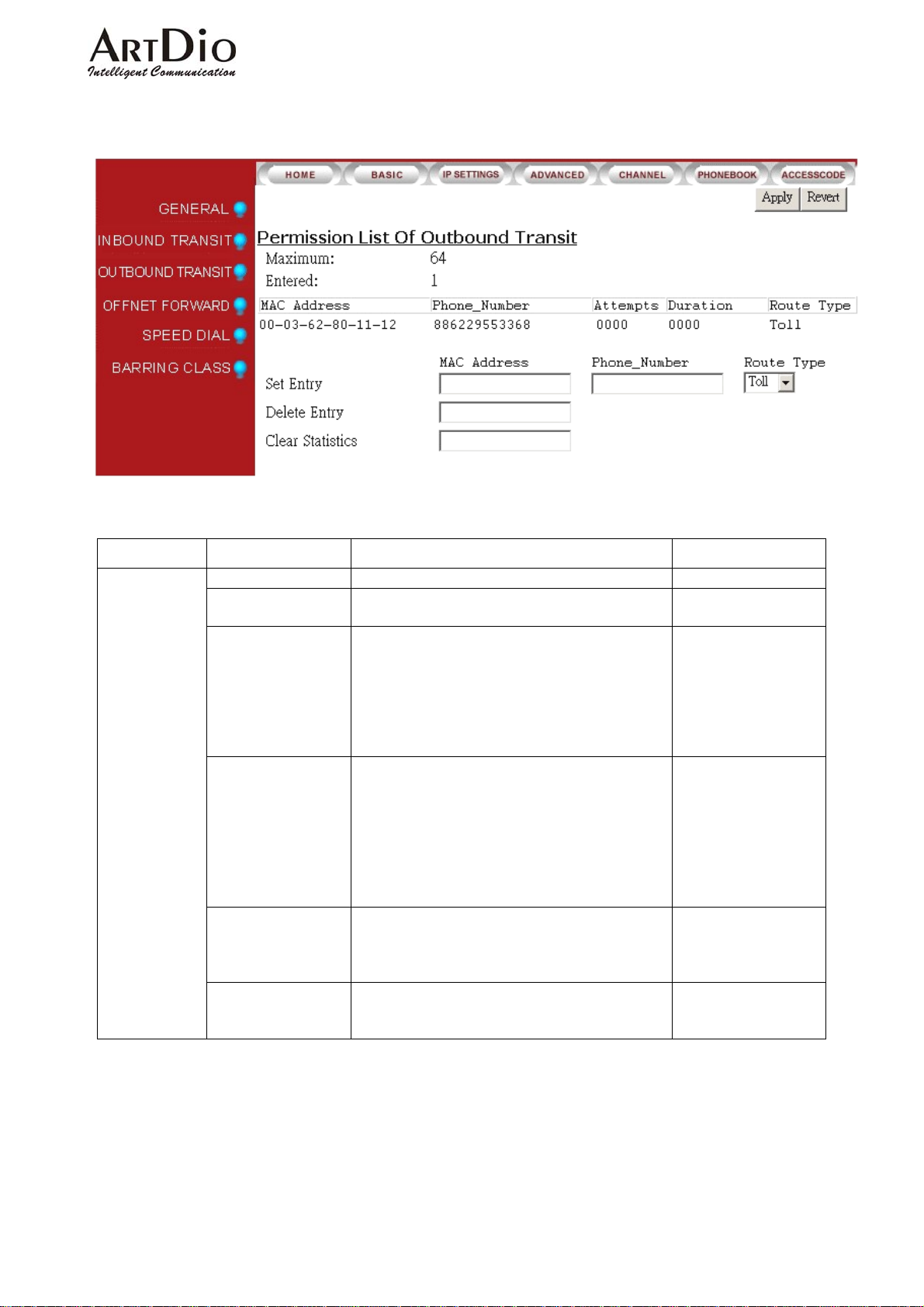
6-1.3 Outbound Transit
ARTDio IPP 1000 Series
Section Item Field Description Default
Permission List
Of Outbound
Transit
Maximum
Entered
Entries List
Set Entry
Delete Entry
Clear Statistics
Maximum number of entries allowed (Read Only)
Displays the number of phone
numbers that have been entered.
Displays all phone numbers permitted to transit.
(Read only)
1) MAC Address: MAC address of permitted
device.
2) Phone Number of permitted device.
3) Attempts: Call attempts
4) Duration: Call duration in the unit of seconds.
Enter the MAC address, phone number, and select
Route Type for devices permitted to transit.
1) MAC Address: Enter the complete MAC
address, for example, 00-03-62-80-13-49.
2) Phone Number: Enter phone number
including country and area code, for example,
886282263368345.
3) Rout e Type: Local or Toll
Remove the device from permission list.
1. MAC Address: Enter MAC address of the
device to be removed. For example,
00-03-62-80-13-49.
Clear attempts and duration of MAC address
device entered. Enter ‘MAC address’ and click
‘Apply’.
(Read Only)
64
0
None
None
None
None
39
Page 41
ARTDio IPP 1000 Series
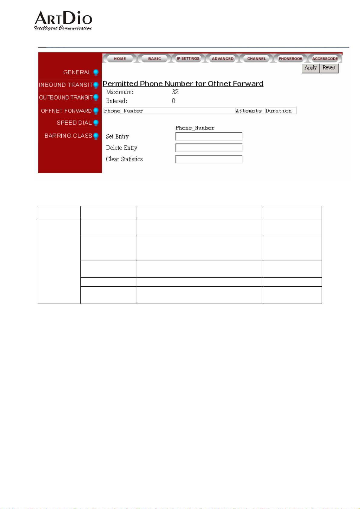
6-1.4 Off-net Forward
Section Item Field Description Default
Permitted Phone
Numbers for
Offnet Forward
Maximum
Entered
Maximum number of entries allowed for off-net
forward calls. (Read Only)
Lists all devices permitted off-net transit, and their
call attempts/duration (Read Only)
32
0
Set Entry
Delete Entry
Clear Statistics
Set permitted phone numbers for off-net fo r war d
calls.
Delete phone numbers from off-net forward calls.
Clears attempts and duration of phone number
entered. Enter phone number and click ‘Ap p l y ’.
40
Page 42
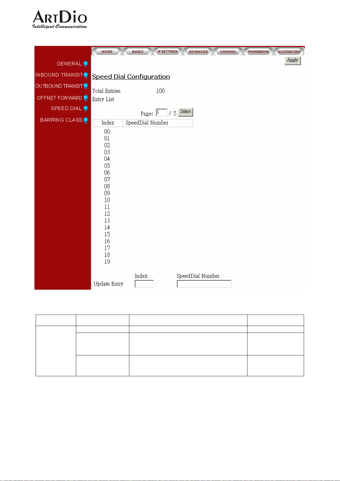
6-1.5 Speed Dial
ARTDio IPP 1000 Series
Section Item Field Description Default
Speed Dial
Configuration
Total Entries The maximum entries that can be set 100
Entry List
Update Entry
Page: 1-5
Index:speed dial index
Speed Dial Number:Phone number
Index:speed dial index
Enter index number to be changed.
Enter new phone number and click ‘Appl y ’.
None
None
41
Page 43
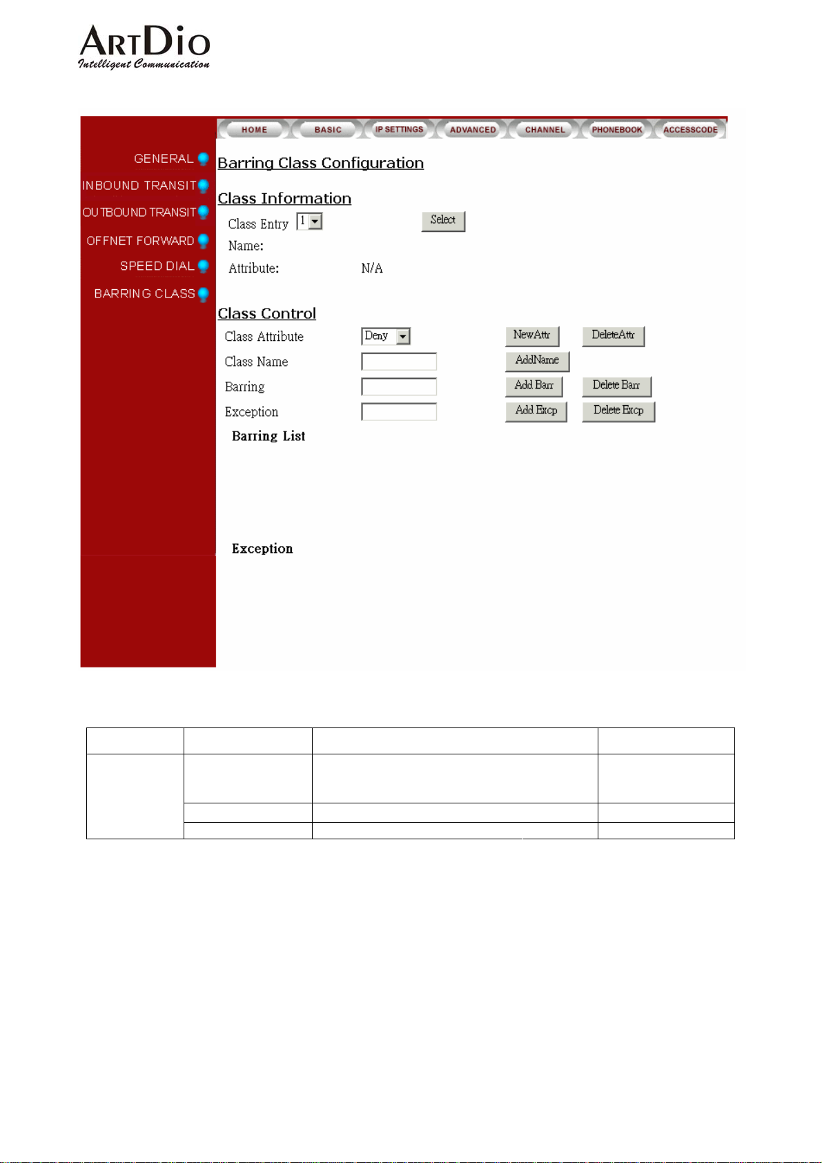
6-1.6 Barring Class
ARTDio IPP 1000 Series
Section Item Field Description Default
Class
Information
Class Entry Select barring class from ‘Class Entry’ field drop
down box.
Click ‘Select’.
Name
Attribute Display the attribute (Read Only) N/A
The name of the class
(Read Only) None
42
Page 44

ARTDio IPP 1000 Series
Section Item Field Description Default
Class Control
Class Attribute The class attribute can be set to either “Deny” or
“Accept”. Both attributes have a barring table and
an exception table. Each class contains only one
attribute.
DENY: Denies all numbers except those
specified in the exception table. The barring
table does not need to have elements because
“Deny” in general is used to bar all numbers
except those found in the exception table.
ACCEPT: Accepts
numbers listed in the barring table. However
the numbers specified in the exception table
will not be barred.
New Attr: Assigns an attribute to the selected
barring class
Delete Attr: Deletes an attribute from the selected
barring class
Class Name The name of the class
Add Name: Assigns a name to the barring class.
The name can be any text up to 15 digits.
Barring
Add Barr: Adds a barring number to an attribute
that has been assigned to a selected barring class.
The maximum length is 19 digits.
Delete Barr: Deletes a barring number from an
attribute that has been assigned to a selected
barring class. The maximum length is 19 digits.
Exception
Add Excp
attribute that has been assigned to a selected
barring class. The maximum length is 19 digits.
Delete Excp: Deletes an exception number from
an attribute that has been assigned to a selected
barring class. The maximum length is 19 digits.
Barring List The barring list shows all the barring
numbers which have been assigned
to each attribute that has been
assigned to a selected barring class.
Exception The exception list shows all the
exception numbers which have been
assigned to each attribute that has
been assigned to the selected barring
class.
:
Adds an exception number to an
all numbers except the
(Read Only)
(Read Only)
43
Page 45
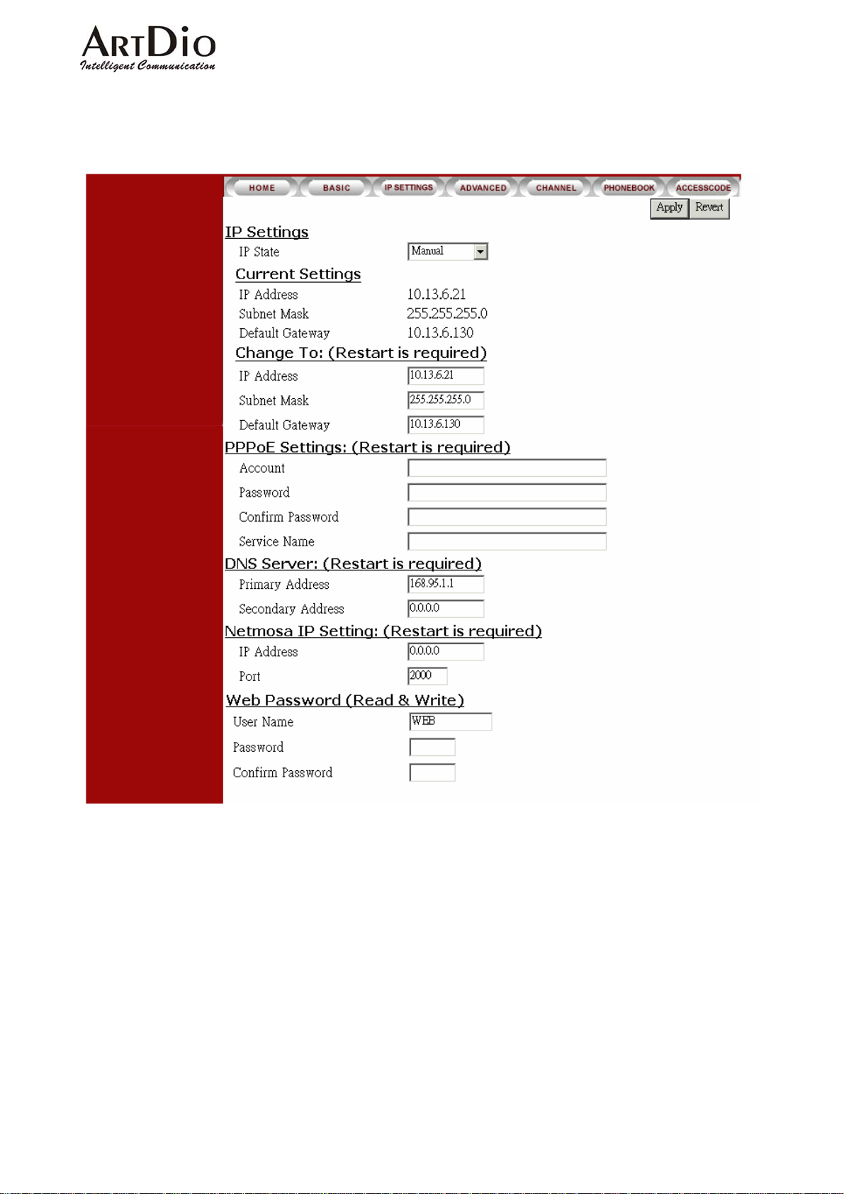
6-2 IP Settings
ARTDio IPP 1000 Series
44
Page 46
ARTDio IPP 1000 Series
Section Item Field Description Default
IP Settings
Ch ange To Enter the IP address that will be used after next
PPPoE Settings
Web Password
IP State Method of obtaining:
Manual: Entered by user (Static IP)
Auto(DHCP): Assigned by DHCP serve r
PPPoE: Assigned by PPPoE of ISP
Current Setting Displays the configured IP address, subnet mask
address, and default gateway. (Read only)
restart, Including:
1. IP Address
2. Subnet Mask Address
3. Default Gateway
(This item is used only in Manual mode of IP
Setting.)
Account Supplied by the ISP None
Password Supplied by the ISP None
Confirm Password Confirm the password None
Service Name To be supplied by the ISP in lieu of account, and
password
Primary Addre ss Enter the DNS Server address
e.g. 168.95.1.1(Taiwan)
Secondary Address Enter an alternate DNS Server address None
IP Address Enter IPN IP address None IPN IP Setting
Port Enter IPN Control Port None
User Name Enter User name WEB
Password Enter Password None
Password Confirm Confirm the password None
Manual
192.168.0.2
255.255.255.0
192.168.0.1
None
168.95.1.1 DNS Server
45
Page 47
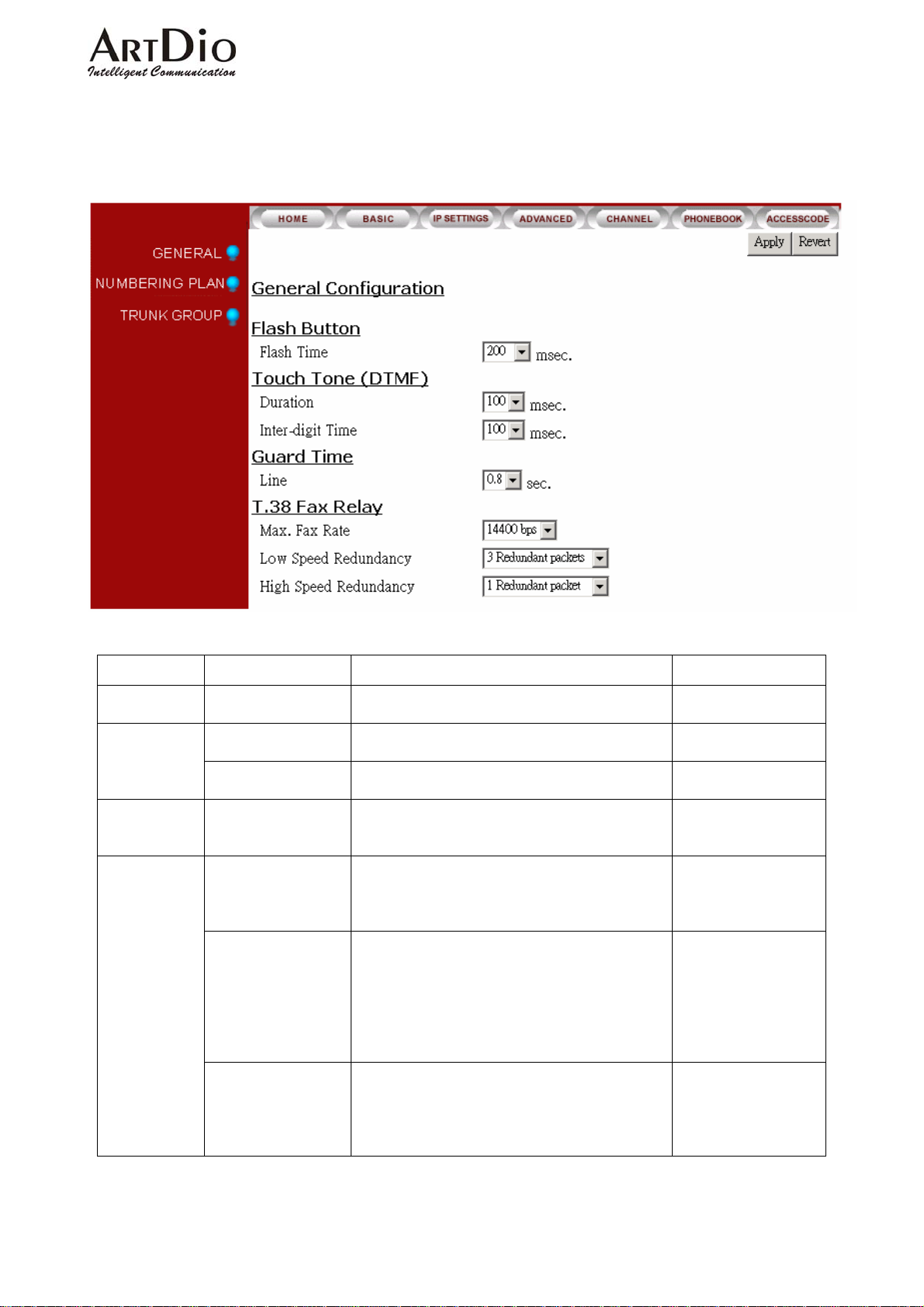
6-3 Advanced
6-3.1 General
ARTDio IPP 1000 Series
Section Item Field Description Default
Flash Button Flash Time
Duration
(DTMF)
Inter-digit Time
Guard Tim e Line
T.38 Fax Relay
Max. Fax Rate
Low Speed
Redundancy
High Speed
Redundancy
Set the flash time duration in seconds. Select an
entry from the ‘Flash Time’ field drop-down box.
Sets the DTMF duration. Select an entry from the
‘Duration’ field drop-down box.
Select an entry from ‘Inter-digit time’ drop down
box.
Sets minimum time between in-coming calls.
Select an entry from the ‘Line’ field drop-down
box.
The system will accommodate 2400 / 4800 / 7200
/ 9600 / 12000 / 14400 bps.
Select an entry from the ‘Max. Fax Rate’ field
drop-down box.
Set the number of redundant packets in low speed.
No Redundant Packets
1 Redundant Packets
2 Redundant Packets
3 Redundant Packets
4 Redundant Packets
5 Redundant Packets
Set the number of redundant packets in high
speed.
No Redundant Packets
1 Redundant Packet
2 Redundant Packets
200 msec
100 msec T ouc h Tone
100 msec
0.8 sec
14400 bps
3 Redundant Packets
1 Redundant Packet
46
Page 48
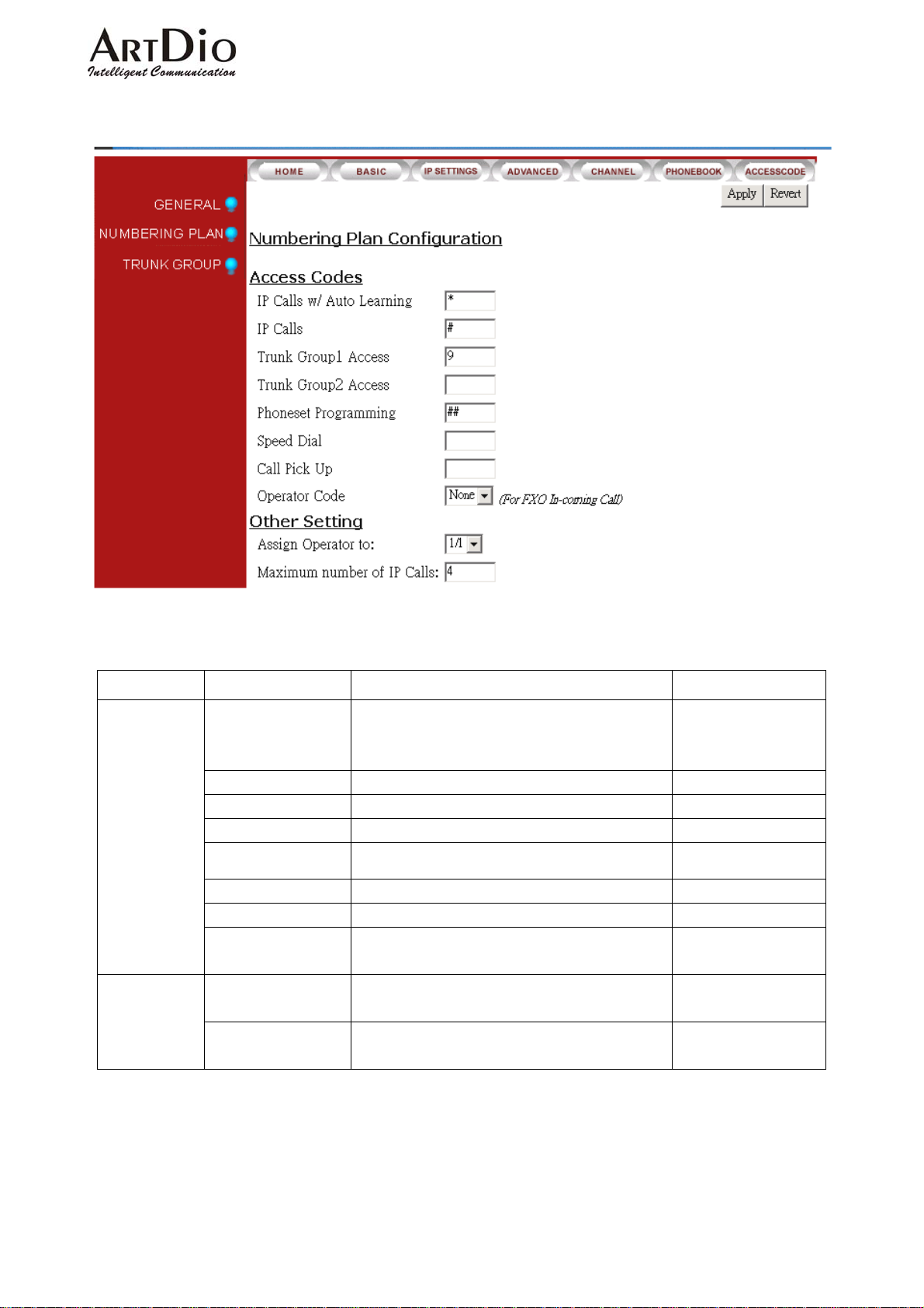
6-3.2 Numbering Plan
ARTDio IPP 1000 Series
Section Item Field Description Default
Access Code
Other Setting
IP Call Auto Learning
IP Call
Trunk Group1 Access
Trunk Group2 Access
Phoneset
Programming
Speed Dial
Call Pick Up
Operator Code
Assign Operator to:
Maximum number of
IP Calls:
Will automatically learn IP calls.
Enter an access code in the ‘IP Calls
w/Auto-learning’ field, Click Apply.
Enter an access code in the field, Click Apply.
Sets the trunk group 1 access code
Sets the trunk group 2 access code
Sets phoneset access code
Sets speed dial access code
Sets call pick up access code
Select an operator code from the ‘Operator Code’
field drop-down box
Select an extension number from the ‘Assign
Operator To: ’ field drop-down box
Enter a maximum number for IP calls in the field
drop-down box
*
#
9
None
##
None
None
None
1/1
4
47
Page 49
ARTDio IPP 1000 Series
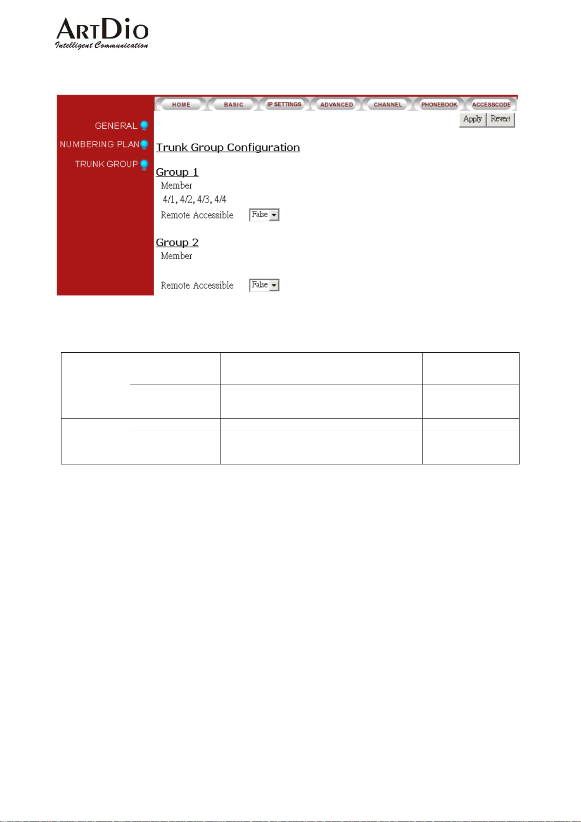
6-3.3 Trunk Group
Section Item Field Description Default
Group1
Member Assignment of in-coming line to trunk group 1
Remote Accessible Permits Transit Call for group.
In the ‘Remote Accessible; field drop-down box,
select ‘True’, or ‘False’ , Click Apply.
Member Assignment of in-coming line to trunk group 2 None Group2
Remote Accessible Permits Transit Call for group.
In the ‘Remote Accessible; field drop-down box,
select ‘True’, or ‘False’ , Click Apply.
4/1,4/2,4/3,4/4
False
False
48
Page 50
6-4 Channel
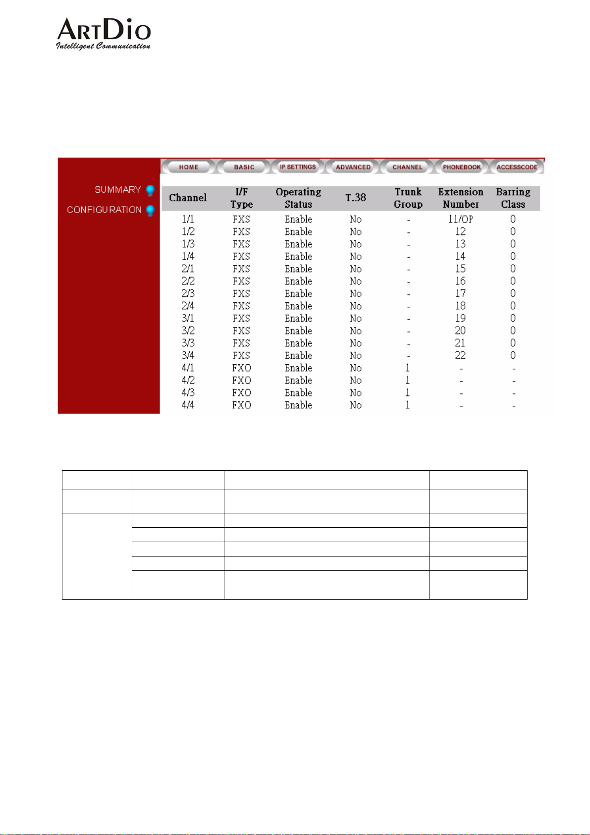
6-4.1 Summary
ARTDio IPP 1000 Series
Section Item Field Description Default
SUMMARY Channel
I/F T ype
Operating Status
T,38
Trunk Group
Extension Number
Barring Class
Lists the channels, and extension (Read Only)
Displays extension I/F type (Read Only)
Displays extension operating status (Read Only)
Displays extension fax enablement (Read Only)
Displays trunk group assignment
Displays local extension assignment
Displays extension barring group assignment
4 groupings of 4 ports
each
FXS / FXO
Enable
NO
None
None
None
49
Page 51
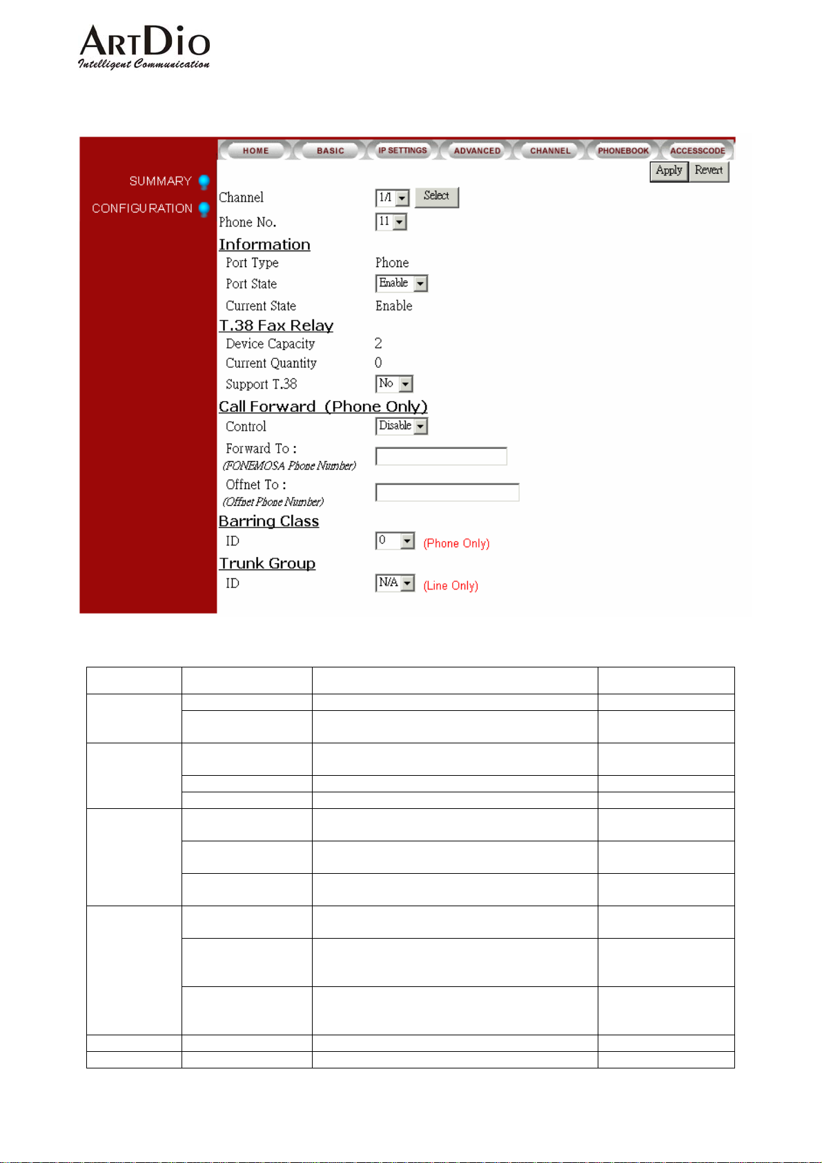
6-4.2 Configuration
ARTDio IPP 1000 Series
Section Item Field Description Default
Channel Select channel/extension to be configured 1/1
Phone NO. Select local extension in the ‘Channel’ field drop
down box, click ‘select’.
Information
T.38 Fax Relay
Call Forward
Barring Class ID Select the extension’s Barring Class ID 0
Trunk Group ID Select the extension’s Trunk Group I D N/A
Port Type Displays extension’s FXO or FXS designation
(Read Only)
Port State Select port state, ‘Enable’ or ‘Disable’ Enable
Current State Displays extension’s state ‘Enable’ or ‘Disable’
Device Capacity Displays the maximum number of devices the T.38
protocol can support.
Current Quantity Displays the number of devices the T.38 protocol
is supporting.
Support T.38 Select ‘Yes’ or ‘No’ to assign the T.38 protocol to
support the extension
Control Select ‘Enable’ or ‘Disable’ to assign the
extension’s call forwarding capability
Forward to
(IPP Phone Number)
Offnet to
(Offnet Phone number)
Enter the IPP phone number to receive calls
forwarded from the extension.
Click ‘Apply’
Enter offnet phone number to receive calls
forwarded from the extension.
Click ‘Apply’
2
0
NO
Disable
None
None
50
Page 52
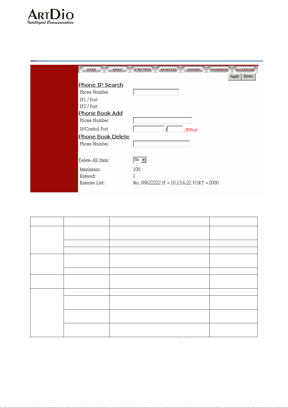
6-5 Phone Book
ARTDio IPP 1000 Series
Section Item Field Description Default
Phone IP Search
Add
Phone Book
Delete
Phone Number
IP1/Port
IP2/Port
Phone Number
IP/Control Port
Phone Number
Delete All Static
Maximum
Entered
Entries List
Enter the phone number to find the IP address
Click ‘Apply’
Indicates the IP address is Public. (Read Only)
Indicates the IP address is Private. (Read Only)
Enter the phone number for Phone Number listing.
Click ‘Apply’
Enter the IP address, and UDP port. Click ‘Apply’
Enter the phone number to be deleted from the
phone book. Click ‘Apply’
Select ‘Yes’ or ‘No’
Display the maximum phone book
entries
Display the number of phone book
entries
List all phone number that are in the
database (Read only)
(Read Only)
(Read Only)
None
None Phone Book
None
None
No
100
0
51
Page 53
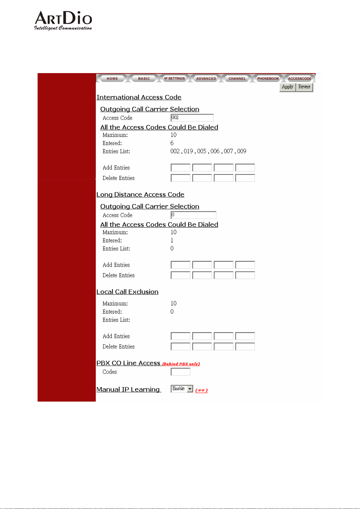
6-6 Access Code
ARTDio IPP 1000 Series
52
Page 54
p
ARTDio IPP 1000 Series
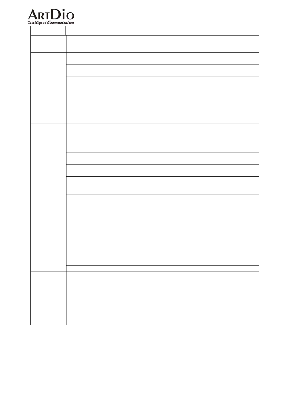
Section Item Field Description Default
Outgoing Call
Carrier Selection
(International)
All the access
codes could be
dialed
(International)
Outgoing Call
Carrier Selection
(Long Distance)
All the access
codes could be
dialed
(Long Distance)
Local Call
Exclusion
PBX CO Line
Access
Manual IP
Learning
Access Code
Maximum
Entered
Entries List
Add Entries
Delete Entries
Access Code
Maximum
Entered
Entries List
Add Entries
Delete Entries
Maximum
Entered
Entries List
Add Entries
Delete Entries
Codes
Enter the international access code to be used for
outgoing international calls.
The maximum entries of all international access
codes that could be dialed. (Read only)
Display all codes that have been entered. (Read
only)
List of all international access codes that could be
dialed. (Read only)
Add entries of all international access codes
allowed to be dialed. Four entries can be entered at
a time.
Delete entries of all international access codes
allowed to be dialed. Four entries can be entered at
a time.
The long distance access code to be inserted on
outgoing long distance calls.
The maximum entries of all long distance access
codes allowed to be dialed. (Read only)
Lists the codes that have been entered. (Read only) Depends on the region
Lists all long distance access codes allowed to be
dialed.
Add entries of all long distance access codes
allowed to be dialed. Four entries can be entered at
a time.
Delete entries of all long distance access codes
allowed to be dialed. Four entries can be entered at
a time.
The maximum entries of all local calls that can be
dialed. (Read only)
The local calls that have been entered.
Lists all local codes that can be dialed.
Add the leading digits of phone number that are
not local call. For an outbound transit call, if the
first digits of phone number are matched with the
hone number, it will not be treated as local call. It
will be treated as a long distance call.
Delete an entry of local call exclusion.
PBX CO line access code, the code to access an
external phone line. If pause is required for 1-5
seconds, a character P can be added to the access
code. Each addition character P adds one second
to the pause. For example dialing 9PP, would
allow a 2 second pause.
Controls the function of Manual IP Learning.
Select ‘Enable’ or ‘Disable’
Click ‘Apply’
(Read only)
(Read only)
Depends on the region
ID configured
10
Depends on the region
ID configured
Depends on the region
ID configured
None
None
Depends on the region
ID configured
10
ID configured
0
None
None
10
0
None
None
None
Enable
53
Page 55
t
(
)
ARTDio IPP 1000 Series
7. Special Applications
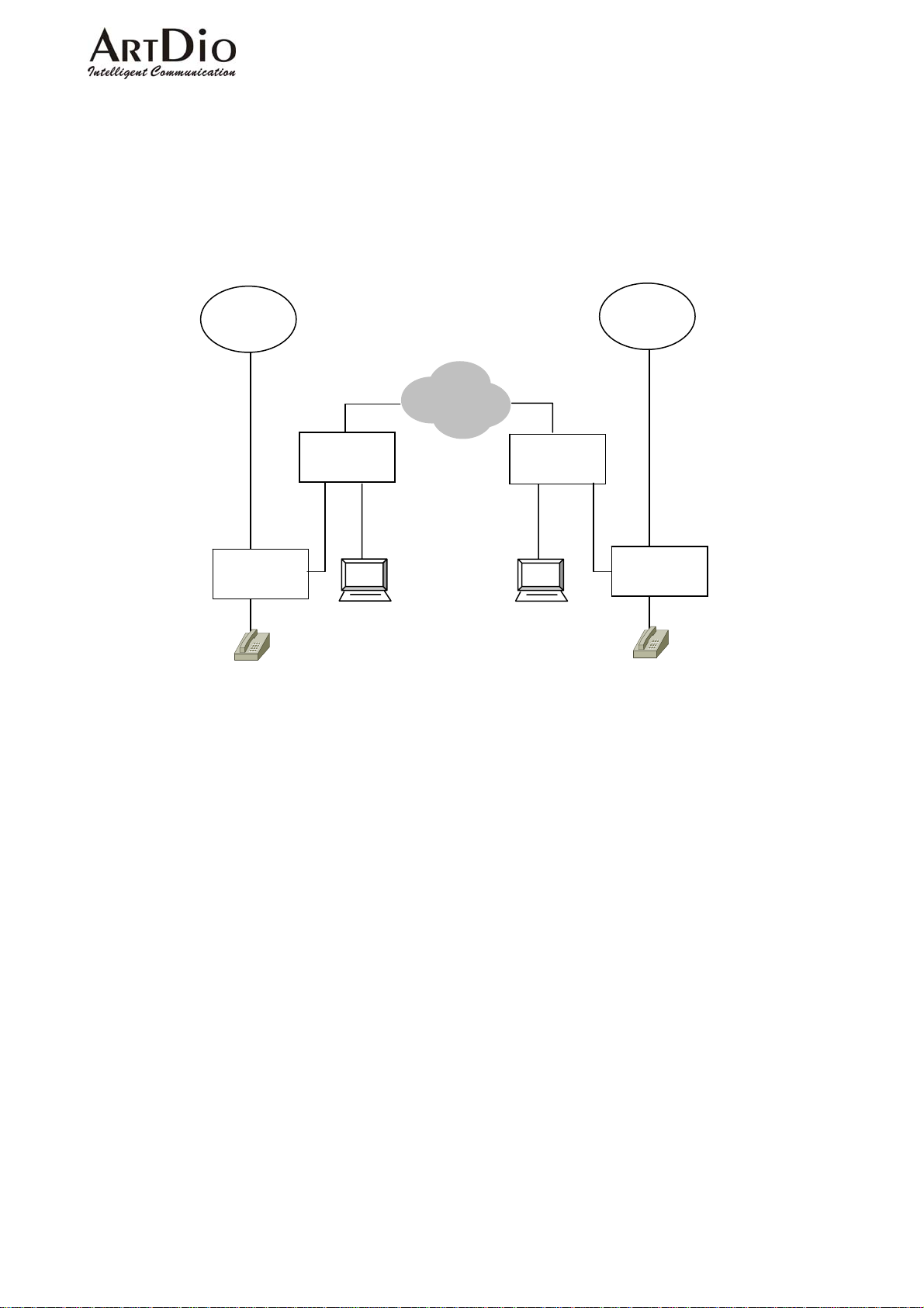
7-1 Using NAT Via Private IP
IPP can be configured as a private IP address and inter-connected with other IPH/IPE units.
Carrier
WAN side
(Public IP)
IP Sharing
IP
WAN side
(Public IP)
IP Sharing
Phone Line
LAN side
LAN side
IPH
(Private IP)
PC
Private IP
PC
(Private IP)
Carrier
Etherne
Phone Line
IPP
(Private IP)
Architecture with IP sharing device
7-1.1 Virtual Servers on the IP sharing device
For the most part, IP sharing devices act as clients, not as servers. However, if you want to
install servers such as web, mail or devices like the IPP unit on the LAN side, you must configure
such devices as virtual servers with the IP sharing device. The IPP unit behaves as a server, so you
must configure the IP sharing device to treat it as a virtual server.
Every server uses a particular port (e.g. TCP port 80 for Web servers and TCP port 21 for FTP
servers). The IPP unit uses UDP port 2000. The method used to configure a virtual server is to map
the server port to the private IP that the virtual server is assigned. Thus is so that incoming packets
that are meant to reach a particular server port are correctly forwarded to the server’s assigned
private IP address on the LAN side of your network. For example, if you want to install a web
server on the LAN side of your network using a private IP address (e.g.192.168.1.1), you must
configure the correct port mapping on the IP sharing device so that it is able to forward all packets
that are intended for destination port TCP 80 on the server’s assigned private IP address
(e.g.192.168.1.1:80). The mapping should be as follows: TCP port 80 <-> 192.168.1.1.
54
Page 56
ARTDio IPP 1000 Series
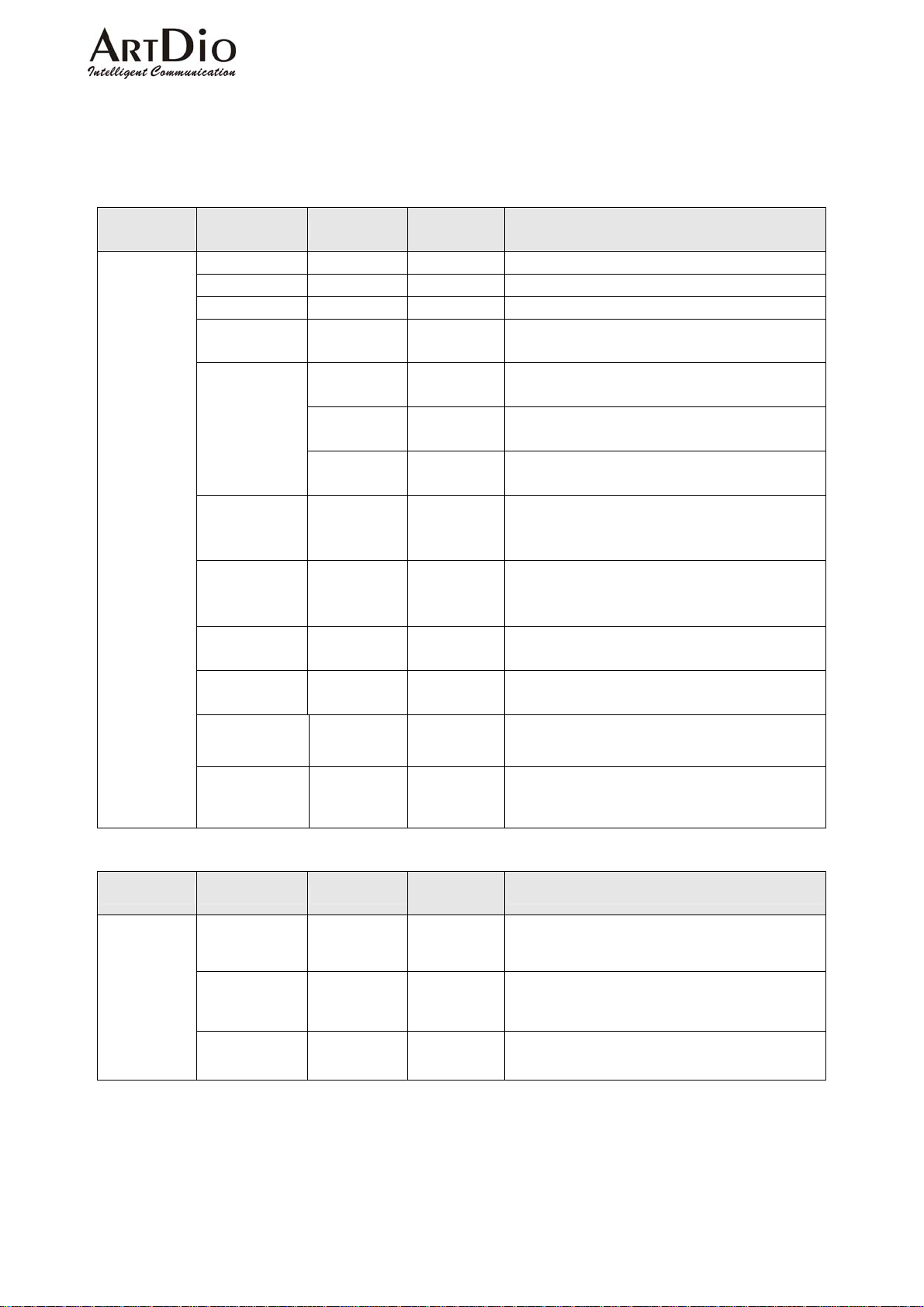
7-1.2 Tested IP Sharing Devices
Although the IPP unit works with most commonly used IP sharing devices, there are still some
devices that have compatibility issues and will not work with the IPP unit. The Following table lists
the IP Sharing devices that have been tested and are known to work with the IPP unit.
Type Brand Model
Stand Alone
D-Link DI-704 2.50 build9
SMC 7004BR R1.86
SOHOmate HIP-120E 1.93S
Corega BAR
SW-4P
Cisco
1600 IOS 12.0
1750 IOS 12.0
2600 IOS 12.0
Linksys BEFN2PS4 1.36p7
SOHOware NBG600 1.16 Sep.
GemTek AirPass
WX-2211
TREND GateLock 1.01.1230
Surecom
Software
Version
R1.10 Apr.
16, 2002
Mar.02,
2001
28 2000
4.62
Test Result
Special configurations are not required.
Special configurations are not required.
Special configurations are not required.
Special configurations are not required.
You will be required to map UDP port
2000 to the IPP unit’s private IP address.
You will be required to map UDP port
2000 to the IPP unit’s private IP address.
You will be required to map UDP port
2000 to the IPP unit’s private IP address.
Works only if it configures as a server
(server mode).
The IPP unit’s IP address must be
configured on the ‘game zone’ of the IP
sharing device.
UDP port 2000 must be configured as a
virtual server.
UDP port 2000 must be configured as a
virtual server.
DMZ must be configured. Only one IPP
is allowed.
NetExcell ver 1.02
Type Brand Model
Software
Tiny Software WinRoute
Based
Microsoft Windows
Microsoft Windows
98 SE2
ME
Software
Version
4.1.25
DMZ must be configured. Only one IPP
is allowed.
Test Result
UDP port 2000 must be configured as a
Virtual Server.
Special configurations are not required.
Special configurations are not required.
55
Page 57
ARTDio IPP 1000 Series
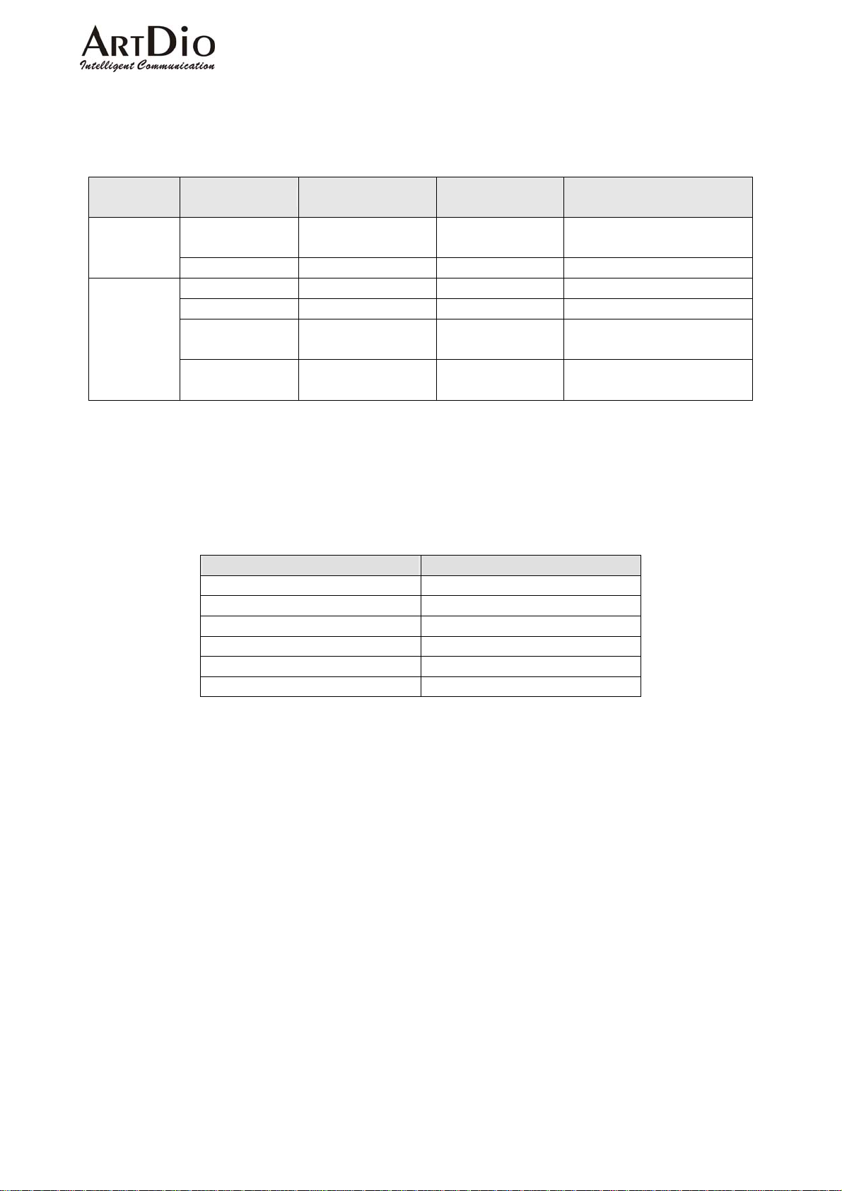
7-1.3 IP Sharing Devices Not Recommended
The following IP Sharing devices have been tested and have been found not to work with the
IPP unit.
Incompatible Stand Alone
Software
Version
Test Result
Incompatible
Incompatible
Type Brand Model
3Com 3CRWE50194
HomeConnect
Accton WildFire Linux 2.2 Incompatible
Software
Based
Ositis Software WinProxy 4.0 Incompatible
Microsoft Windows 2000 Incompatible
Microsoft
Microsoft
Windows
XP
Windows
NT4.0
7-2 Firewall
Lists the port numbers of IPP.
Packet Type Port Type
Control Port UDP 2000
Voice Port UDP 4000 – 4031
FAX Port UDP 4032 – 4047
FTP Port TCP 21
WEB Port TCP 80
Telnet Port TCP 23
56
Page 58
8. FILE MANAMEMENT
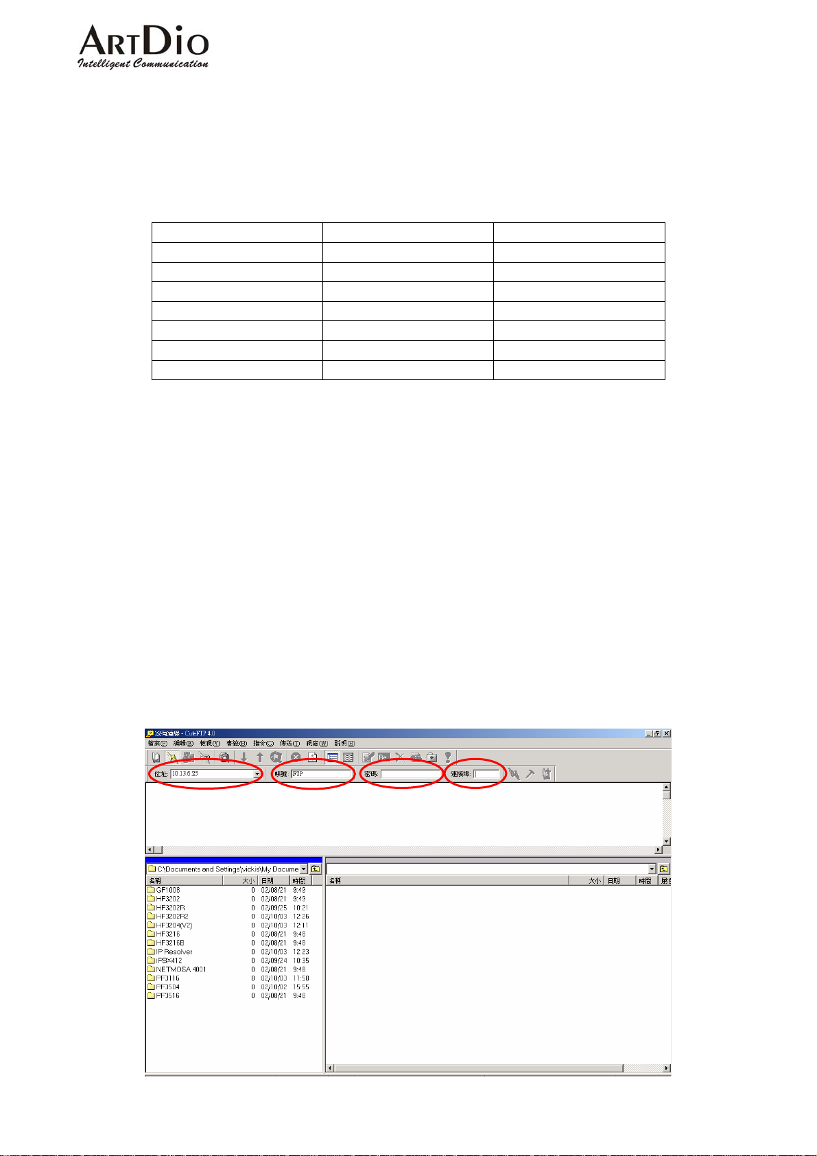
8-1 File Type
File File Type Description
HFIPPX.CFG System Configuration System Configuration
HFIPPX.GT1 Greeting #1 Greeting
HFIPPX.GT2 Greeting #2 Greeting
HFIPPX.GT3 Greeting #3 Greeting
HFIPPX.GT4 Greeting #4 Greeting
HFIPPX.GT5 Greeting #5 Greeting
HFIPPX.RUN RUN File Software
8-1.1 File Update Using FTP
Preparing the update firmware
ARTDio IPP 1000 Series
1. Gateway power on
2. PC power on
3. Connect to the IP (The FTP must be accessed via the IP)
4. The Gateway, and PC have previously been set for IP, subnet, Gateway
5. Connect the NULL MODEM CABLE to the console
6. The system is configured to update files
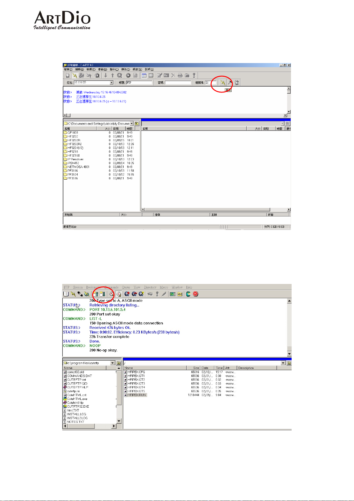
FILE Update Using FTP (The example web page is Chinese version)
1. Run the FTP Client software (such as CuteFTP)
Enter the IP address, User Name, (default:FTP ), Password (the FTP Password is the same
as the console’s, and default is empty), and Port Number:21
57
Page 59
ARTDio IPP 1000 Series
2. Selecting ‘Connect’ will synchronize the PC and IPP systems. A successful connection will
call up the Gateway File.
3. Download software to PC hard disc, Select ‘RUN’ click ‘Upload’ at the top of the page.
Note:The updated file must be the same name as the original gateway file, for example:
hfIPPx.run).
58
Page 60
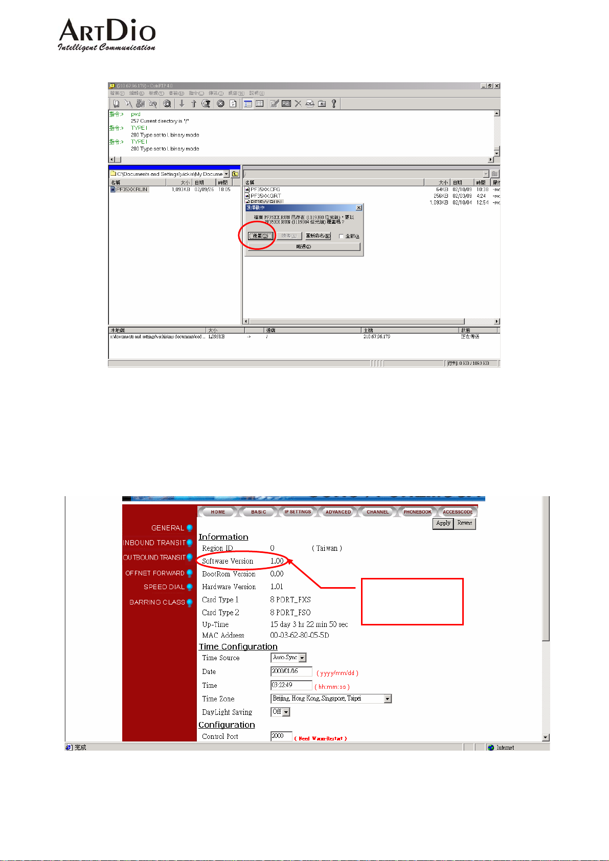
4. Select ‘Overwrite’
ARTDio IPP 1000 Series
5. After selecting ‘Overwrite’, check to insure the time and date are the same. Return to the
Web Management Page, select ‘Cold Re-start’ in the ‘Re-start’ field drop-down box. The
update is complete.
Note:To confirm the update has been successful go to Web Management Page,
‘BASIC’, and see that the ‘Software Version’ field has changed.
Confirm the
software version
59
Page 61

ARTDio IPP 1000 Series
9. NETWORK MANAGEMENT
9-1 Use Of The System Console
9-1.1 System Command Summary
User Exec commands:
Enable Turn on privileged commands
Exit Exit from the Exec
Help Description of the interactive help system
Show Show running system information
show:
Dns Show the IP address of domain name server
ethernet FastEthernet port status and configuration
history Display the session command history
IP Display IP configuration
running-config Show current operating configuration
version System hardware and software status
Privileged Mode:
Configure Enter configuration mode
Delete Reset configuration
Disable Turn off privileged commands
Exit Exit from the EXEC
Help Description of the interactive help system
Ping Send echo request to destination
Reload Halt and perform cold start
Restart Halt and perform warm start
Show Show running system information
Global Mode:
Dbflush DataBase flush
Dns Set the IP address of domain name server
End Exit from configure mode to privileged mode
Exit Exit from configure mode
Help Description of the interactive help system
IP Global IP configuration subcommands
Manager Enable/Disable the specific management function
No Negate a command or set its defaults
Password Modify password of enable command
pppoe PPPoE configuration subcommands
regional_id Set regional id
service_port Set service port number
Description
60
Page 62
ARTDio IPP 1000 Series
9-2 Use Of The Web Management Page
Use console to configure IP information and open the web page using the configured IP.
9-3 Management Via telephone
Pick-up the phone, and listen for the dial tone. Dial #9999. When the three beeping tone signal is
heard, then the item numbers can be dialed.
9-3.1 Command Summary
Item
DESCRIPTION
For Specific FXS Port
01 Call Forward
02 Forwarding In-coming Calls 1~19 (Digits)
03 Off-net Forward Number 1 ~ 22 (Digits)
04 Alarm Set hh*mm*x hh: 00~23; mm: 00~59;
05 Gain Control
06 Password 4 Digits
07 After office hours greeting
operation
0/1;0:Disable;1:Enable
x: 1 : one only 2 : periodic
0:Factory Default
1:+2 db
2/22/222:-2/-4/-6 db
0/1:0:Disable, 1:Enable
Item
DESCRIPTION
For All Interface
91 Call Barring Bypass
92 Reset Password (Per-Port) 11~22 (2digits)
Reset the selected channel’s password to “0000”
93 After Work Operation 0 : Disable ; 1: Enable
96 Play Greeting 1~5 (1digit) Record Greeting File (1~5)
98 System Restart 1: Enable
99 Record Greeting 1~5 (1digit) select Greeting File(1~5)
*
#
0
#
9
#
#
Parameter
Parameter
Start record
End record
Start Play back
Stop play back
Start save
Stop save
Leave record state
61
Page 63
ARTDio IPP 1000 Series
10. INTER-CONNECTION VIA IPN
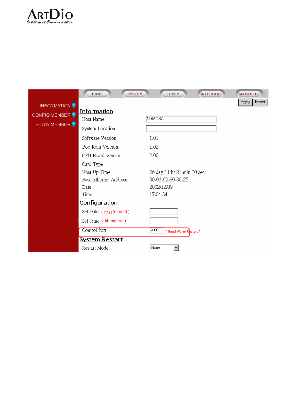
When IPP is configured as a IPN IP and port number, the IPP will join the IPN group. IPN
must be configured as the MAC and phone number of IPP.
10-1 IPN Control Port
62
Page 64
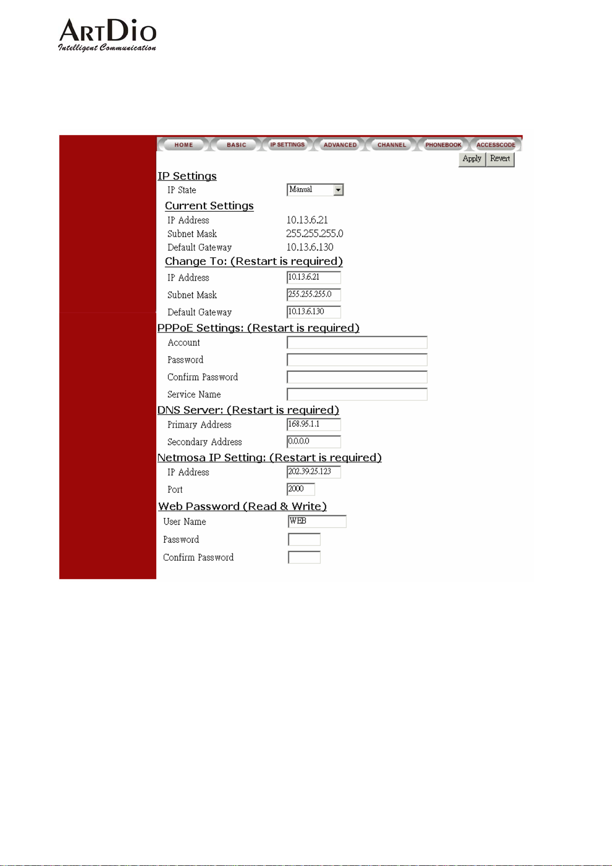
10-2 IPP Setting IPN IP
ARTDio IPP 1000 Series
63
Page 65
ARTDio IPP 1000 Series
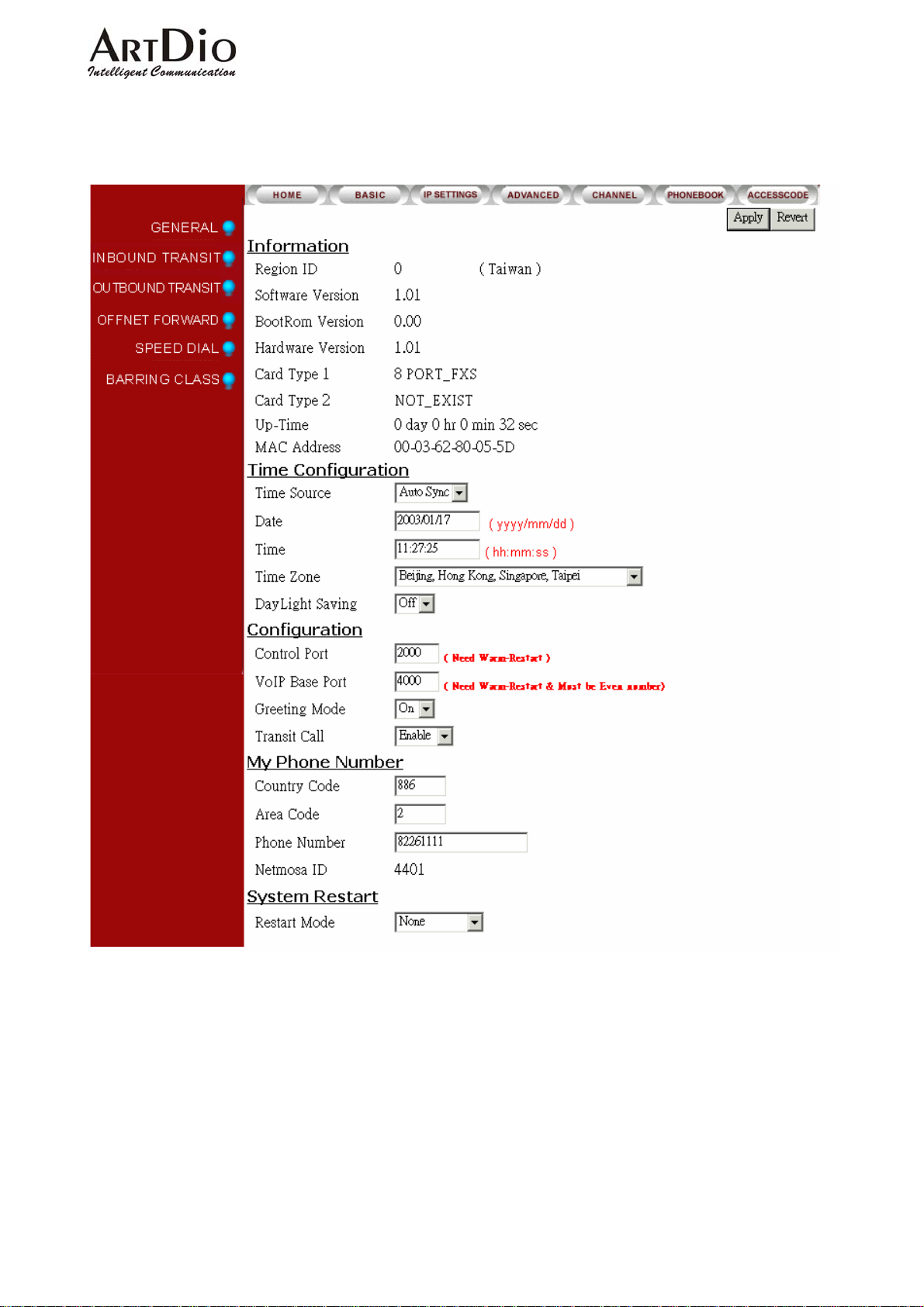
10-3 IPP WEB PAGE
Open the web page to confirm the setting is working. Select BASIC/GENERAL
64
Page 66

ARTDio IPP 1000 Series
11. Specifications
Number of ports 4 FXO + 12FXS
FAX relay T.30/T.38
FXS interface Transport protocols
FXO interface Loop start, 2 wire
Connectors IDC connectors
Voice compression G.711/G.729AB
Silence suppression VAD, CNG
Echo cancellation G.165/G.168 16ms
Jitter buffer Adaptive jitter buffer management
Gain control In/Out +/-6db
Packet time 40 ms
Transport protocols RTP, RTCP
Call control protocol Proprietary MGCP
Phone book Auto-learning, manual configuration
LAN Ports
Number of ports Two Ethernet Ports
Interfaces 10Base-T/100BASE-TX auto-negotiation
Connectors RJ-45 connectors
Management Web browser, Telephone set, Telnet, Console
IP address Static, Private, PPPoE, NAT, DHCP
Software Up-grade FTP
General Information
Power External power adapter
Voltage:100VAC 240VAC Frequency: 50/60Hz .
Power consumption 70 W
Dimension 440mm x 66mm x 254 mm
Working environment
Operating temperature: 0 to 50℃
Storage temperature: -10 to 70℃
EMI certification FCC part 15 , CE Mark , VCCI
PTT regulations FCC part 68 , , iDA , JATE
Safety UL , CCIB , CB
65
Page 67

12. Appendix
12-1 List of Region ID By Country
ID NO. Country ID NO. Country ID NO. Country ID NO. Country
01 Argentina 02 Australia 03 Philippines 04 Portugal
05 Brazil 06 Canada 07 China 08 Russia
09 Sweden 10 Vietnam 12 France 13 Germany
15 Hong Kong 18 India 22 Italy 23 Japan
24 Korea 26 Malaysia 27 Mexico 28 Netherlands
ARTDio IPP 1000 Series
29
40 Spain 42 Switzerland 43 Taiwan 44 Thailand
46 British 47 USA 60 Iran 61 Dubai
New Zealand
36 Singapore 38 Slovenia 39 South Africa
66
 Loading...