

Page 1
Direct Thermal Printer
AL-D460 Labelprinter
(4B-2054K)
User Manual
Page 2

Contents
Copyright statement............................................................................................................. 1
Cautions ...............................................................................................................................2
I. Product............................................................................................................................. 3
II. Receiving........................................................................................................................ 4
2.1 Unpacking and checking accessories.................................................................. 4
2.2 Printer components .............................................................................................. 5
2.2.1 Front view ..................................................................................................... 5
2.2.2 Rear view ...................................................................................................... 5
III. Installation...................................................................................................................... 6
3.1 Install the printer..................................................................................................... 6
3.2 Install the label........................................................................................................ 7
3.3 Install the stripping module – optional ...................................................................8
3.4 Stripping mode – optional...................................................................................... 9
3.5 Install the cutter – optional ................................................................................... 10
IV. LED indicator and button functions............................................................................. 10
4.1 LED indicator ....................................................................................................... 10
4.2 General button functions....................................................................................... 11
4.3 Boot function ........................................................................................................ 11
V. Diagnostic Tool.............................................................................................................. 17
5.1 Enable the Diagnostic Tool program .................................................................... 17
5.2 Printer settings ...................................................................................................... 18
5.3 Calibrate the paper sensor with the Diagnostic Tool ............................................ 18
5.4
Set the Ethernet with the Diagnostic Tool (optional)............................................ 19
VI. Troubleshooting ........................................................................................................... 21
6.1 Common problems............................................................................................... 21
VII. Simple maintenance procedures of the printer........................................................... 25
Page 3

Copyright statement
Information in this subject to change without notice and does not represent a commitment on the part.
No part of this manual may be reproduced or transmitted in any form by any means, for any purpose
other than the purchaser’s personal use, without the expressed written permission..
1
Page 4

Cautions
1. When opening the cover of the printer, keep ngers and other parts of
your body away from the paper exit to avoid crushing injury.
2. If the button battery RTC contained in the main board is not replaced
correctly, the main board cannot be used normally.
3. Please dispose of the used batteries according to the manufacturer’s
operation instructions.
2
Page 5

I. Product
Thank you for purchasing our 4B-2054K series thermal barcode printer. This desktop
printer will provide you with safe, reliable and ecient printing at a reasonable price. By
using it, the volume labels can be printed in a wide range of texts or graphic formats.
Meanwhile, its superior function and easy operation make it your best choice among the
thermal barcode printers of the same level.
The 4B-2054K series printer provides thermal printing. The printing speed is adjustable
from 2.0, 3.0, 4.0, 5.0 to 6.0 inches per second. It applies to a variety of printing materials,
including paper rolls, paper slices and fan-fold labels. In addition, the printer has the
built-in 1D and 2D barcodes that are commonly used, a TTF font and eight sets of English
numeric fonts in dierent sizes, and supports printing in 4 dierent directions. And through
the zoom function, the fonts can be enlarged. All these will enable you to improve the label
printing eciency signicantly.
3
Page 6

II. Receiving
This printer is specially packaged to protect against possible damage in transit.
However, since the printer may still be subjected to unexpected damage during
transportation, you are kindly required to check the packaging and all units carefully when
receiving the printer. In case of obvious damage, please contact the sales dealer directly and
indicate the severity of the damage. If necessary, you should keep the packaging materials
for returning the printer.
2.1 Unpacking and checking accessories
Once you have received your barcode printer, place it on a clean, steady table and
carefully remove the packaging materials. Check if the following items are included:
One printer
Paper supply kit (1" core)
One USB cable
One power supply
One power cord
One copy of quick installation guide
Dealer's options:
Peel-off module (factory optional)
Ethernet interface (factory optional)
WIFI interface(factory optional)
Bluetooth interface(factory optional)
RTC battery (factory optional)
Cutter module (factory optional)
User’s options:
External paper roll holder (O.D. 214 mm with 1" or 3" core)
Bushing of paper roll shaft: 1.5", two
4
Page 7
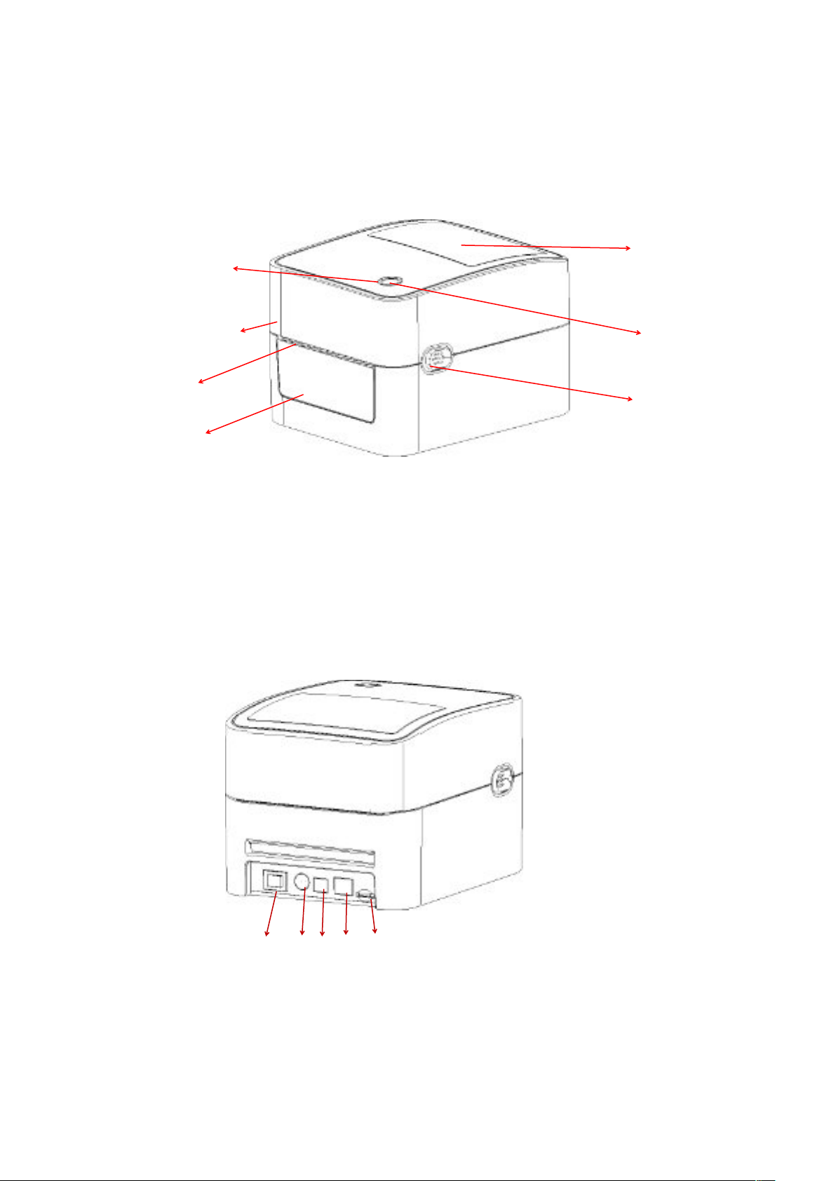
2.2 Printer components
2.2.1 Front view
Feed button
Transparent window
Printer cover
Paper exit
Front panel
2.2.2 Rear view
Power indicator
Cover hook
Power switch
1.
Power socket
2.
3. USB interface
4. Ethernet interface
5. SD card slot
1 2 3 4 5
Note: The transmission interfaces of the printer in the picture will vary depending on the
model of machine you purchase. For the actual transmission interface, please refer to the
catalog specifications.
5
Page 8
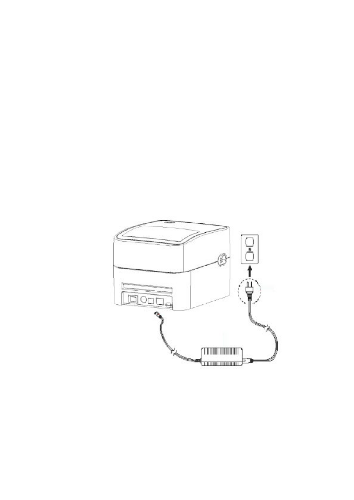
III. Installation
3.1 Install the printer
1. Place the printer on a smooth and steady surface and
make sure the power is off.
2. Plug one end of the parallel port cable, serial port
cable or USB cable into the slot on the back of the
printer, and connect the other end of the cable to the
appropriate slot of your computer.
3. Plug the power cord into the power slot on the back
of the printer and plug the other end into an AC socket.
Note: Make sure the printer power is switched off when
you plug the power cord into the power slot on the back
of the printer.
6
Page 9
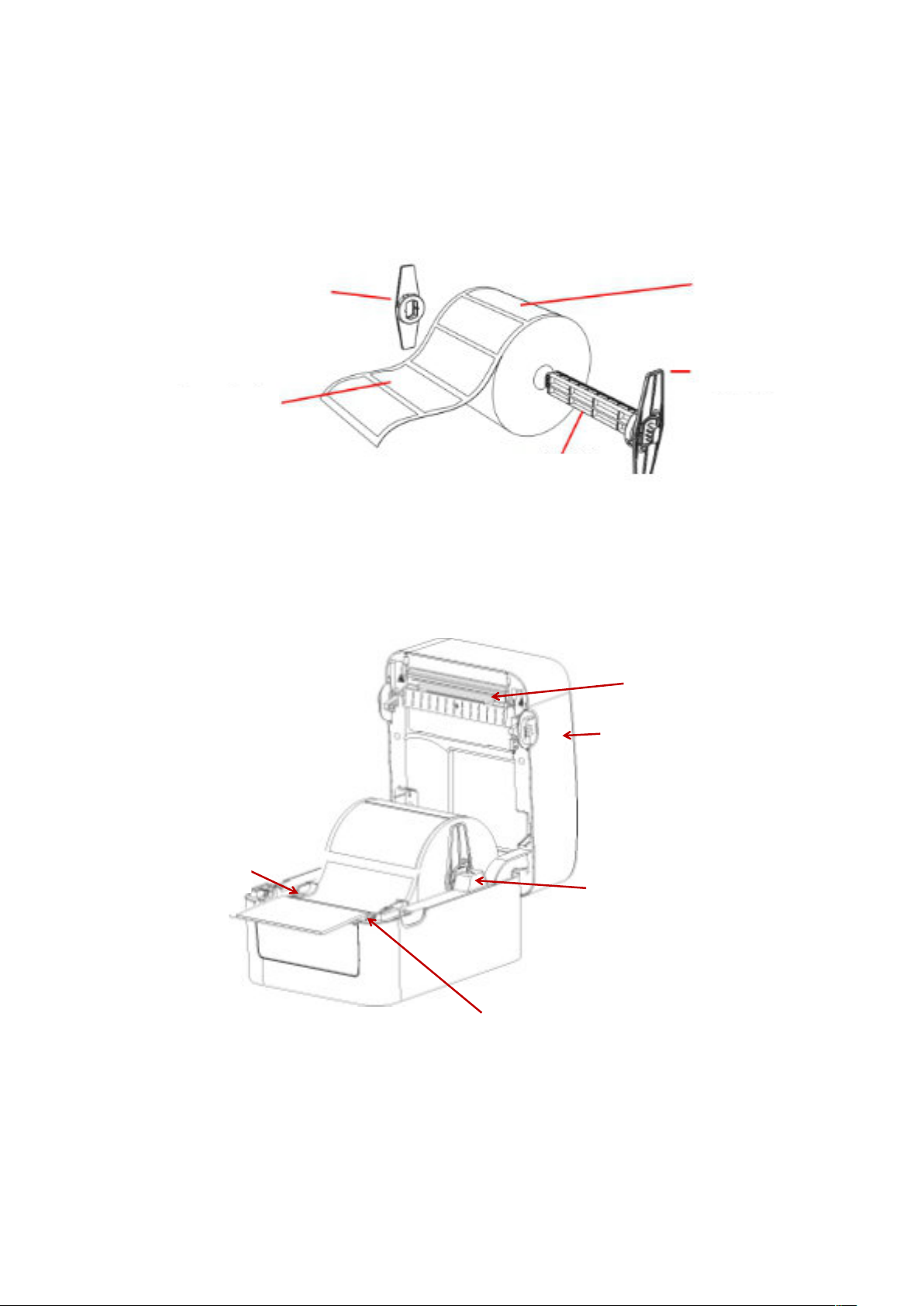
3.2 Install the label
1. Install the label into the paper supply kit. (Fixing plate & Paper roll shaft )
Fixing plate
*1.5"纸卷轴榇套
打印面朝上
Print side up
纸卷轴
1" Paper roll shaft
2. Push the printer cover hook forward with both hands to open the printer cover.
3. Place the label roll on the label roll holder. (Print side up)
4. Pass the label through the paper guide and pull the label over the rubber roller.
Print head
Paper roll
固定片
Fixing plate
纸卷
Paper guide
Printer cover hook
Label holder
Rubber roller
7
Page 10
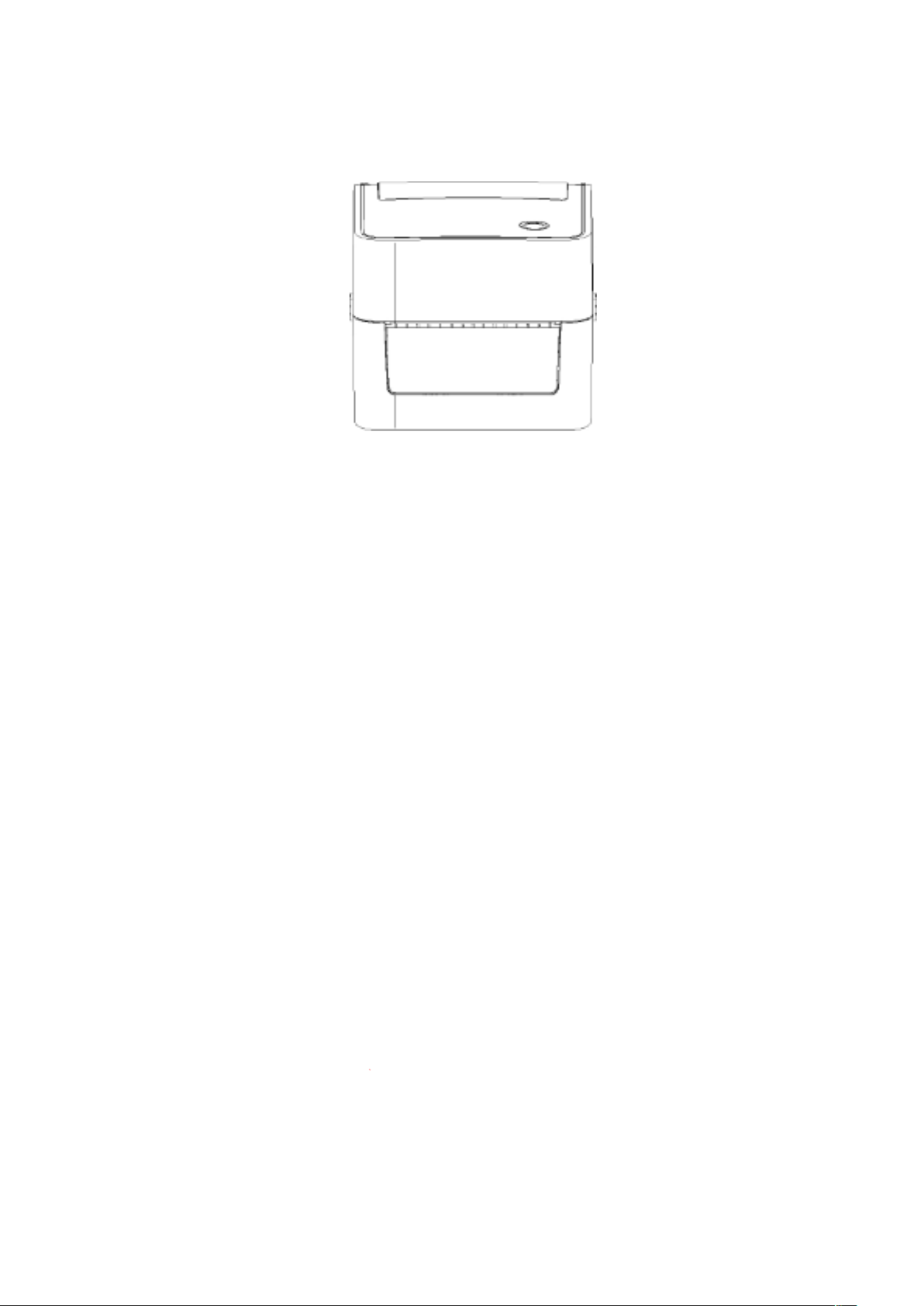
5. Close the printer cover.
Note: To avoid poor printing quality, make sure the printer cover is closed tightly.
3.3 Install the peel-off module – optional
1. Push the cover hook forward with both hands to open the upper cover of the printer.
2. Dismantle the front panel, insert the peel off cable into the corresponding socket hole.
3. Install the peel-o module into the lower inner cover groove.
4. Gently push the stripping panel to lock the lower inner cover.
5. Reinstall the upper cover on the printer.
8
Page 11
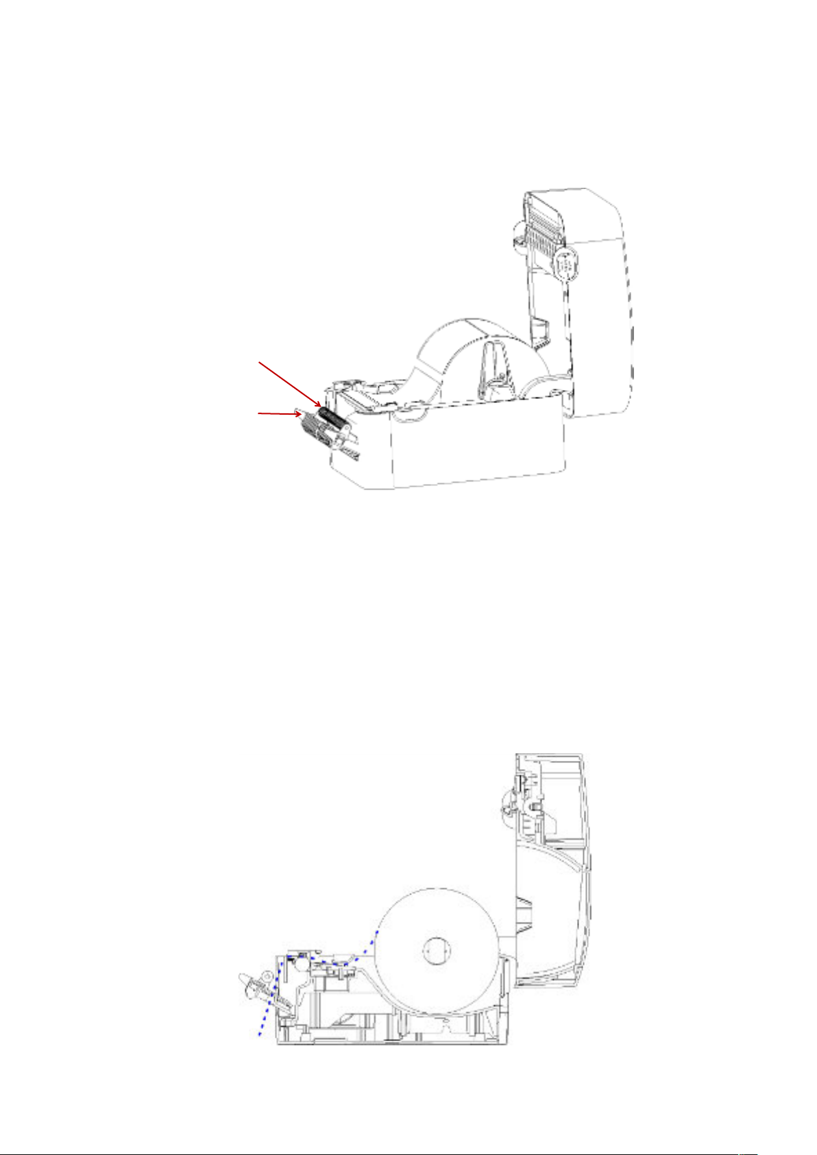
3.4 Install the label with peel-off module
1. Pull the paper stripper apart.
Peel-off roller
front panel
2. Pass the label through the paper guide, and pull the label over the rubber roller.
3. Pass the label through the backing paper exit under the roller (as shown by the blue
dotted line below).
4. Adjust the center offset label guide with your nger to adapt to the edge on the back of
the label.
9
Page 12
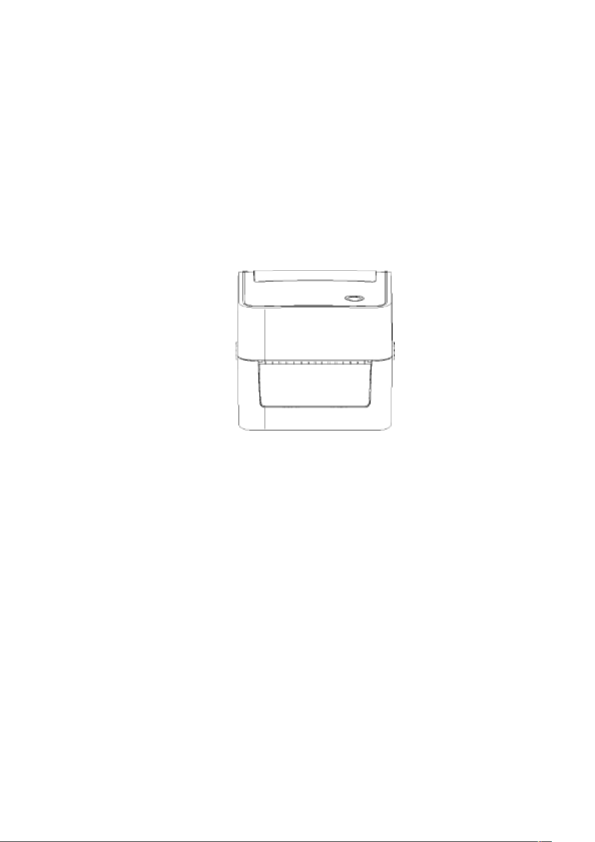
5. Close the front panel.
6. Put on the upper cover of the printer.
3.5 Install the cutter – optional
1. Push the cover release button forward with both hands to open the upper cover of the
printer.
2. Insert the cutter cable into the corresponding socket hole.
3. Align the cutter module with the lower inner cover groove.
4. Gently push the cutter module downward to lock the lower inner cover.
5. Reinstall the upper cover on the printer.
IV. LED indicator and button functions
This printer has one button and one indicator that can display three colors. Pressing the button in
conjunction with dierent colors or collaborating with the power switch will enable the printer to
start multiple functions, such as feeding paper, pausing the printer, calibrating the label sensor,
printing the self-test value, and initializing the printer. Details are described as follows:
4.1 LED indicator
10
Page 13

LED indicator color
Description
Blue (fixed) Power on, printer standby to print.
Boot function
Indicator color cycle mode:
Indicator signal
Function
Blue (blinking) The printer is downloading data or the printer is paused.
Purple
The printer is formatting the data.
Red (fixed) Printer is in head opened or cutter error status.
Red (blinking)
Printing error occurs, e.g. out of paper, paper jam, or memory
error, etc.
4.2 General button functions
1. Paper feeding
When the printer is standby (LED blue xed), the installed paper will move forward one unit
if feed button is pressed once.
2. Pausing of printing operation
While the printer is printing, Press the feed button will pause the operation. At this point,
the power indicator blinks blue. Press the button again to resume the printing.
4.3 Boot function
This printer has four boot functions that can be used to set or test the printer's hardware.
Please follow the steps below to start the boot function:
1. Turn o the printer.
2. Turn on the printer while holding down the button.
3. Release the button with the light signal indicating the required function, as listed in the table
below.
Purple Blue Red Purple Blue Blue
(Blink 5 times) (Blink 5 times) (Blink 5 times) (Fixed blue)
1. Gap/black mark sensor detection
2. Gap/black mark sensor detection,
printing self-test value and entering the
debugging mode
3. Printer initialization (restore factory
defaults)
4. Skip the AUTO. BAS program
Release the button
Release the button
Release the button
Release the button
4.3.1 Gap/black mark sensor detection
This test aims to determine the sensitivity of the label paper sensor after the printer is turned on.
When the user installs a new paper roll of a dierent specification or initializes the printer and
restores it to the factory default value, the label paper gap sensor needs to be re-measured. The
gap detection or black line mark calibration will be completed with your last set value as the
reference value. The default value of this printer sensor is set to gap calibration.
11
Page 14

Please follow the steps below to calibrate the ribbon and gap/black mark sensor:
Internal settings of printer printed in the self-test mode
1. Turn o the printer.
2. Turn on the printer while holding down the feed button.
3. When the indicator blinks red after the rst purple, release the feed button.
Indicator color cycle mode:
PurpleBlueRed (blink 5 times)
Purple (blink 5 times)
Blue (blink 5 times)
Blue (fixed)
Note:
Whether the printer volume label sensor detects the gap or the black mark depends on the GAP or
BLINE command sent to the printer (with your last set value as the reference value, the default
value of the printer sensor is set to gap calibration); for more information on GAP and BLINE
commands, please refer to the TSPL2 programming manual.
4.3.2 Gap/black mark sensor detection; printing self-test value and entering the
debugging mode
This test aims to determine the sensitivity of the label paper sensor after the printer is turned on.
When the user installs a new paper roll of a dierent specication or initializes the printer and
restores it to the factory default value, the label paper gap sensor needs to be re-measured. The
gap detection or black line mark calibration will be completed with your last set value as the
reference value. The default value of this printer sensor is set to gap calibration.
Please follow the steps below to calibrate the label paper by the sensor:
1.Make sure that the label paper is properly installed
2.Turn o the printer
3.Turn on the printer while holding down the feed button
4.When the indicator blinks purple after the rst purple, release the feed button
Indicator color cycle mode:
PurpleBlueRed (blink 5 times)Purple (blink 5 times)Blue (blink 5 times)Blue (fixed)
5.The sensor will calibrate the label paper and the printer will print out the self-test value, and
finally enter the debugging mode and print out the value
6.Turn the machine o and on again to return the printer to the normal printing mode
Note:
Before carrying out the label paper sensor calibration, rst conrm the type of label to be detected
with Diagnostic Tool or GAP/BLINE command. For more information on GAP and BLINE
commands, please refer to the TSPL2 programming manual.
Self-test
When the sensor calibration is completed, the printer prints out the self-test value. Before
connecting the printer to your computer, you can use self-test to conrm that the printer is
functioning properly. The self-test info can be used to check the printing quality of the print head
and know the internal settings of the printer.
12
Page 15
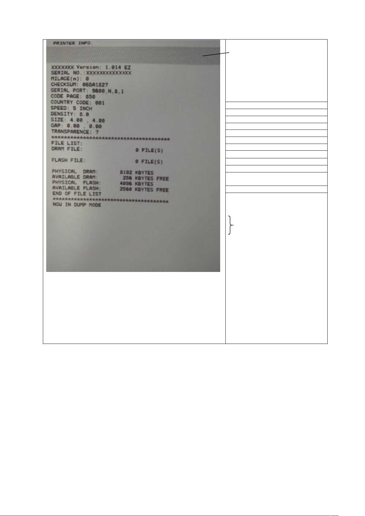
Print head check sample
Model & firmware version
Machine serial number
Print head mileage
Check code
Serial port setting
Character set
Country code
Printing speed
Printing density
Paper size (width, height)
Black mark or gap size (vertical gap,
offset)
Sensor strength
Stored file information
13
Page 16
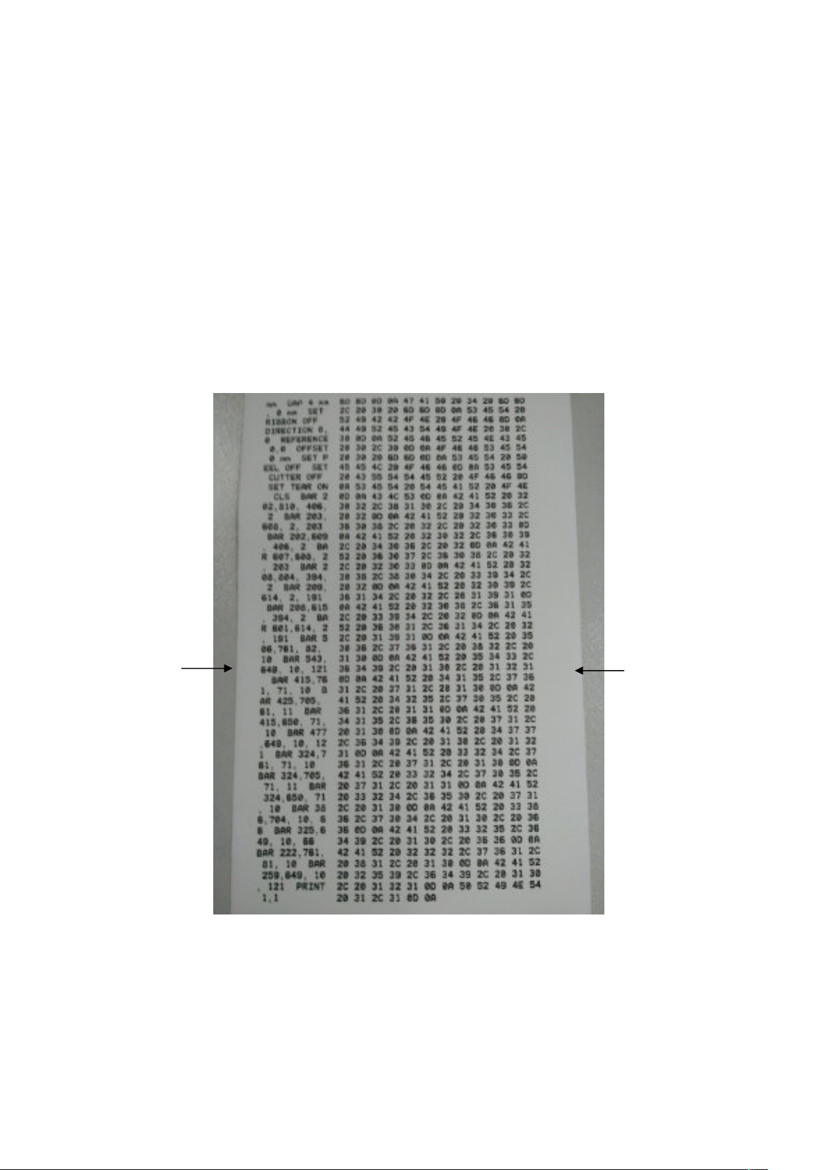
Debug mode
After the self-test is printed, the printer system enters the debugging mode. In the debugging
mode, all the volume labels will be printed as machine code. The ASCII strings on the left are
the data received by the system. The data on the right are printed from the strings on the left, in
hexadecimal values. This function is provided for users or engineers to debug programs. You
only need to restart the printer to leave the debugging mode and return to the normal printing
mode.
ASCII string
Hexadecimal value
data corresponding to
the ASCII string listed
on the left
14
Page 17

Note:
Parameters
Defaults
1. Label paper of 4" wide is required to print all the debugging mode data.
2. Restart the printer to leave the debugging mode and return to the normal printing mode,
or press the FEED button to return to the standby state.
4.3.3 Printer initialization
The printer initialization function is to clear the downloaded files in the memory (DRAM) and
restore the print parameters to the factory default settings.
Please follow the steps below to complete the initialization:
1. Turn o the power.
2. Hold down the feed button and turn on the power. At this point, the power indicator color
will cycle as follows:
Indicator color cycle mode:
PurpleBlueRed (blink 5 times)Purple (blink 5 times)Blue (blink 5 times)Blue (fixed)
3. Release the feed button when the power indicator is blinking blue. At this point, the printer
will be reset, and then the power indicator will blink purple once, and nally the power
indicator will be blue in ready state.
After initialization, the printer conguration is restored to its default values as follows:
Speed
Density
Label width
Label height
Sensor type
Gap setting
Printing direction
Reference point
Oset
Tear-o mode
Peel-o mode
Characters
Country code
Clear flash
IP address
152.0 mm/sec (6 ips) (203DPI)
8
4” (100 mm)
7.9” (180 mm)
Gap sensor
0.16” (4.0 mm)
0
0,0 (upper left corner)
0
On
O
850
001
No
DHCP
15
Page 18

4.3.4 Skip the AUTO.BAS program
The TSPL2 command language allows the user to load an auto-execute file (AUTO.BAS) into
the flash memory. When the printer is turned on, it will be automatically executed according to
the file loaded by the user. When you want to skip the AUTO.BAS after power-on, you can use
this boot function to ignore this auto-execute file.
Please follow the steps below to skip AUTO.BAS:
1. Turn o the power.
2. Hold down the feed button and turn on the power. At this point, the power indicator color
will cycle as follows:
Indicator color cycle mode:
PurpleBlueRed (blink 5 times)Purple (blink 5 times)Blue (blink 5 times)Blue (fixed)
3. Release the FEED button when the indicator is xed blue.
4. The printer will skip the AUTO.BAS program.
16
Page 19
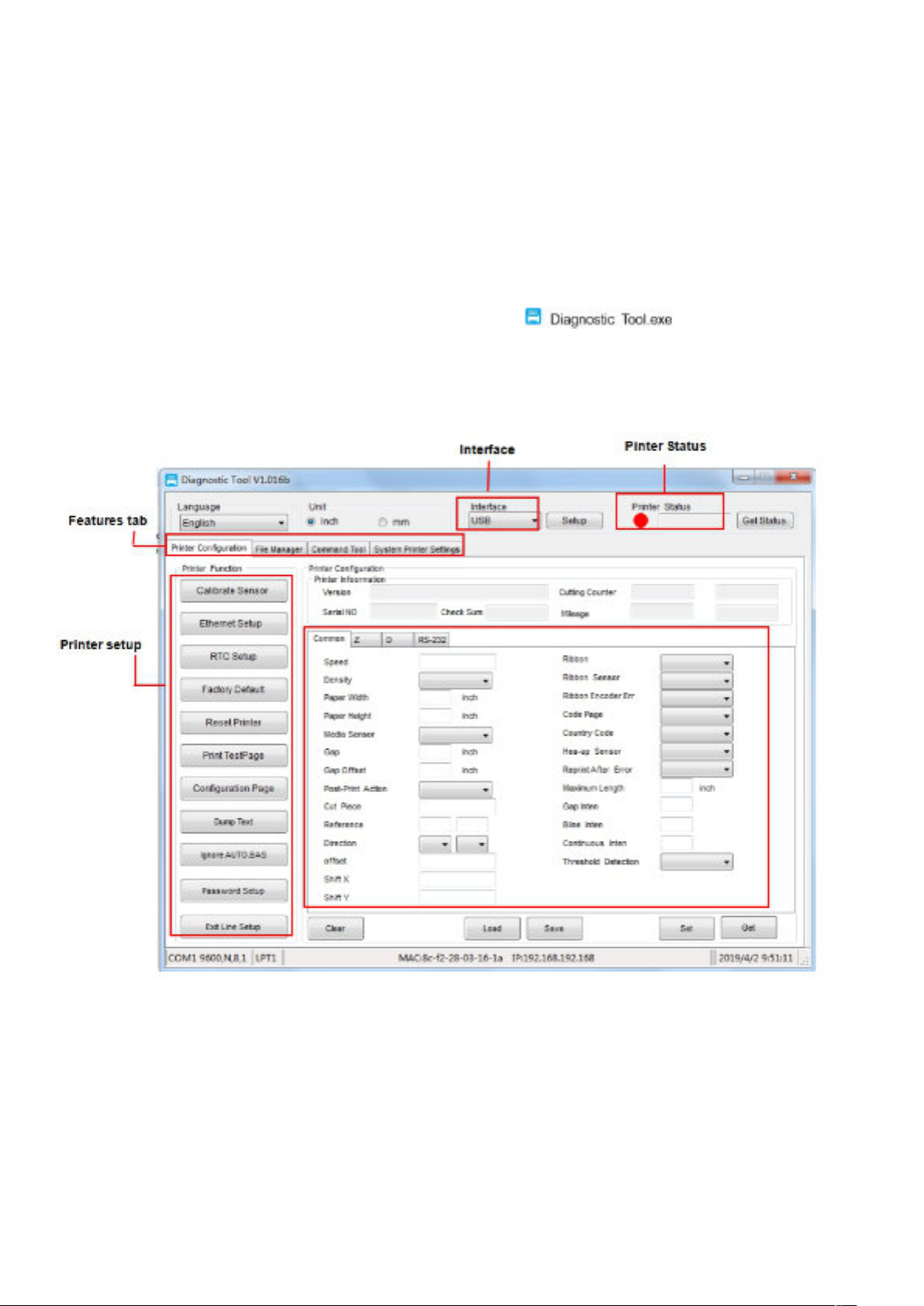
V. Diagnostic Tool
Diagnostic Tool is an easy-to-use window-type utility program that allows you to check the current
status and settings of the printer, download graphic files, programs, font files, etc., and complete
firmware updates according to the actual need. Moreover, it supports creation and download of
dot-matrix fonts, transmission of commands or les and so on. By using it, you can complete the
printer setup, check the printer status and troubleshoot the printer usage problems more easily.
5.1 Enable the Diagnostic Tool program
1. Move the mouse cursor to the Diagnostic Tool image and double click the
left mouse button.
2. After it is started, the main screen shows 4 management pages (printer settings, le
management, communication tools, system printer settings).
17
Page 20
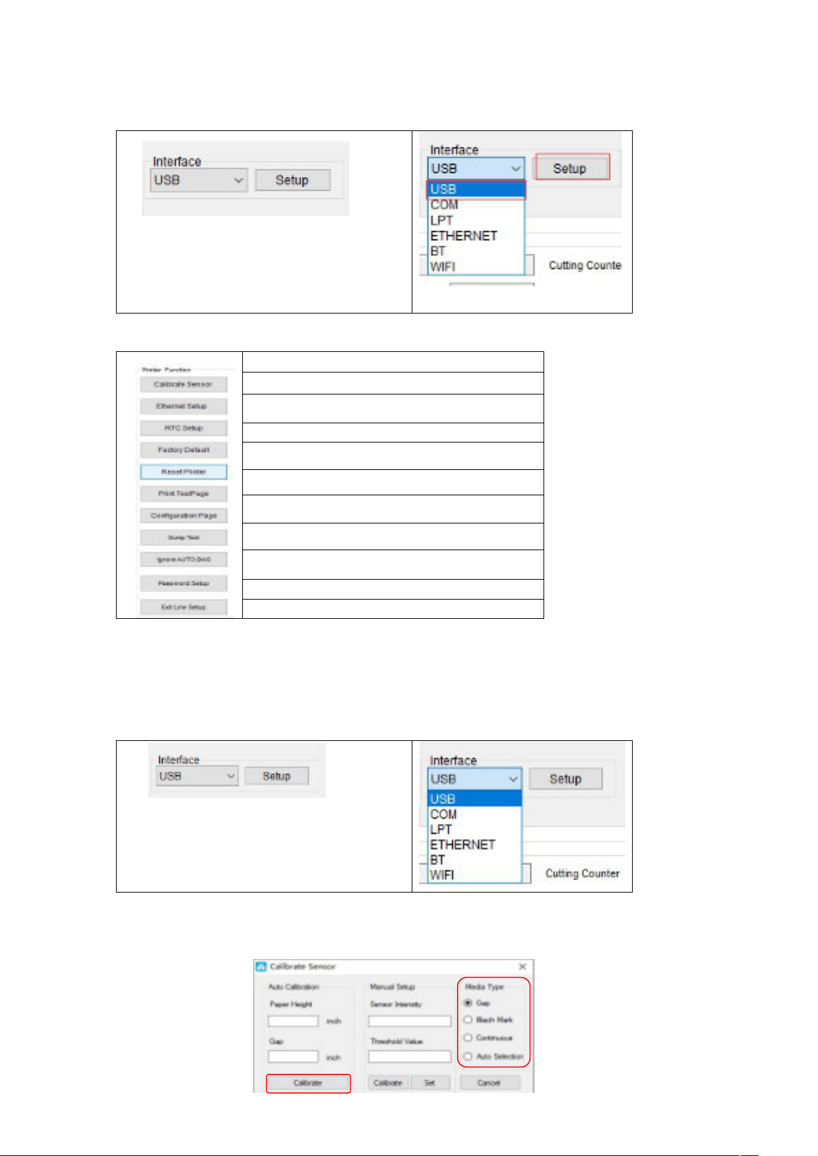
5.2 Printer settings
1. Select the connection interface between your computer and the printer.
The default communication interface of
the Diagnostic Tool program is USB, so if
the computer is connected through USB
cable for transmission, no changes need to
be made to the settings.
2. Click on a function you intend to set in the "Printer Settings".
3. The printer functions in the Printer Settings management page are described as below:
Description
Sensor Calibration
Set Ethernet Network
Set Printer RTC Time Parameters
Restore Factory Defaults and Reboot
Restart the Printer
Print Test Page
Print Self-test Page
Enter Printer Debugging Mode
Ignore the AUTO.BAS File
Set the Diagnostic Tool Password
5.3 Calibrate the paper sensor with the Diagnostic Tool
5.3.1 Automatic correction
1. Make sure that the paper is installed correctly and the print head is closed.
2. Turn on the printer.
3. Start the Diagnostic Tool and set the transmission interface (the default is USB).
The default communication interface of
the Diagnostic Tool program is USB, so if
the computer is connected through USB
cable for transmission, no changes need to
be made to the settings.
4. Click on "Sensor Calibration".
5. Select the paper type and click on "Calibration". The printer will automatically feed the paper
to calibrate the sensor.
18
Page 21
Set the Ethernet with the Diagnostic Tool (optional)
5.4
The Diagnostic Tool program is attached to the Utilities folder in the CD provided with the
printer. The user can use the Diagnostic Tool to set up via USB, RS-232 or Ethernet interface
through Ethernet.
5.4.1 Setting via USB interface
1. Connect USB cable to the printer and the computer.
2. Turn on the power of the printer.
3. Double click the left button of the mouse on icon to start the Diagnostic Tool
program of the printer.
4. The default communication interface of the Diagnostic Tool program is USB, so if the
computer is connected through USB cable for transmission, no changes need to be made to the
settings.
5. In the printer functions page, click the “Network Setting” button in the printer functions to
set IP, subnet mask, and gateway.
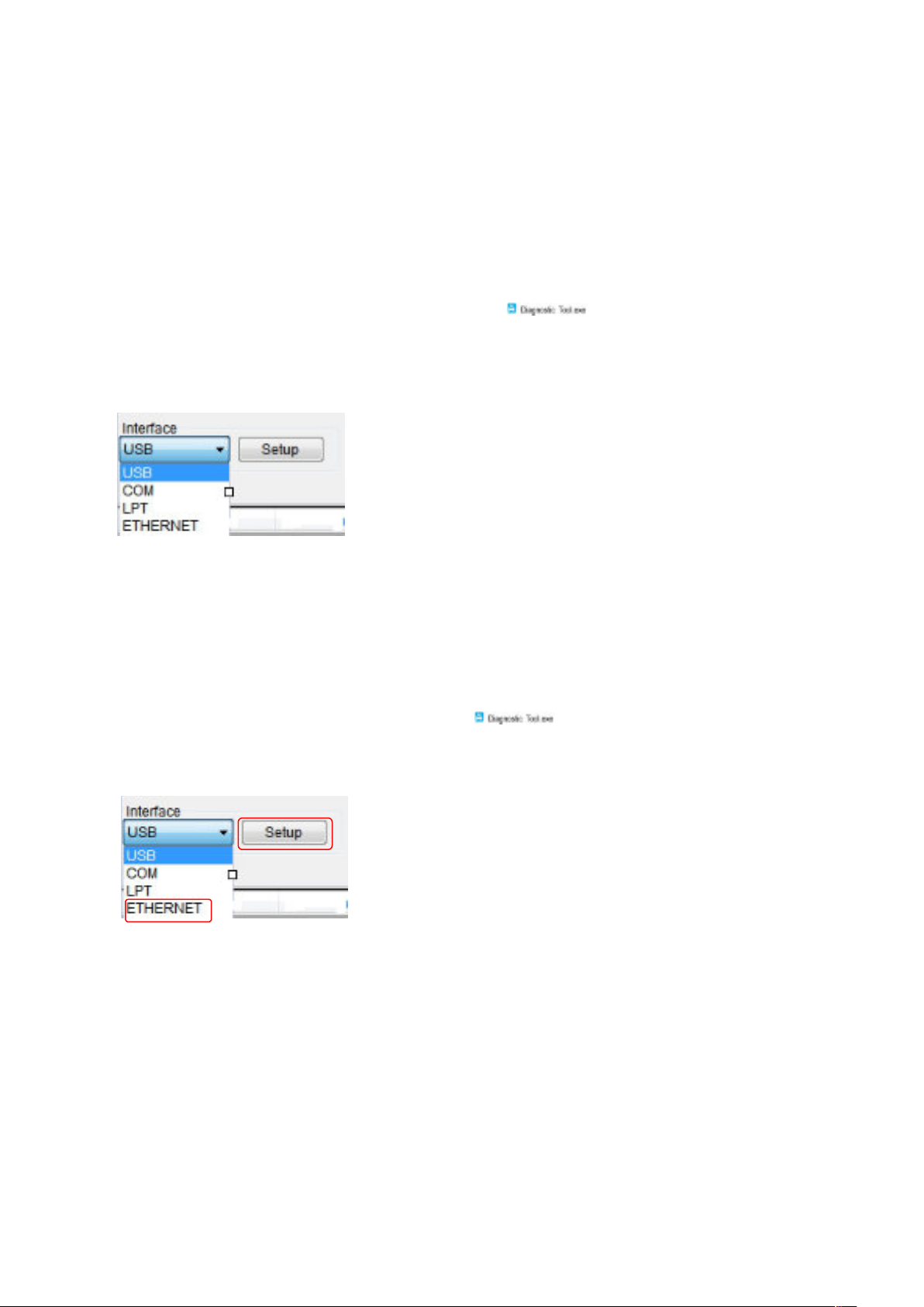
5.4.2 Setting via Ethernet interface
1. Connect the computer and the printer to the local area network.
2. Turn on the power of the printer.
3. Double click the left button of the mouse on
4. Select “ETHERNET” at the communication interface and press the “Setup” button to set IP,
subnet mask, and gateway.
5. Press “Discover” button to nd printers available on the local area network.
6. Select the printer to be set on the left side, and its IP address will appear in the “Name/IP
address of printer” on the right side.
7. Press “Change IP” button to set the assigned IP address or automatically obtain the IP location
(DHCP).
icon to start the Diagnostic Tool
19
Page 22
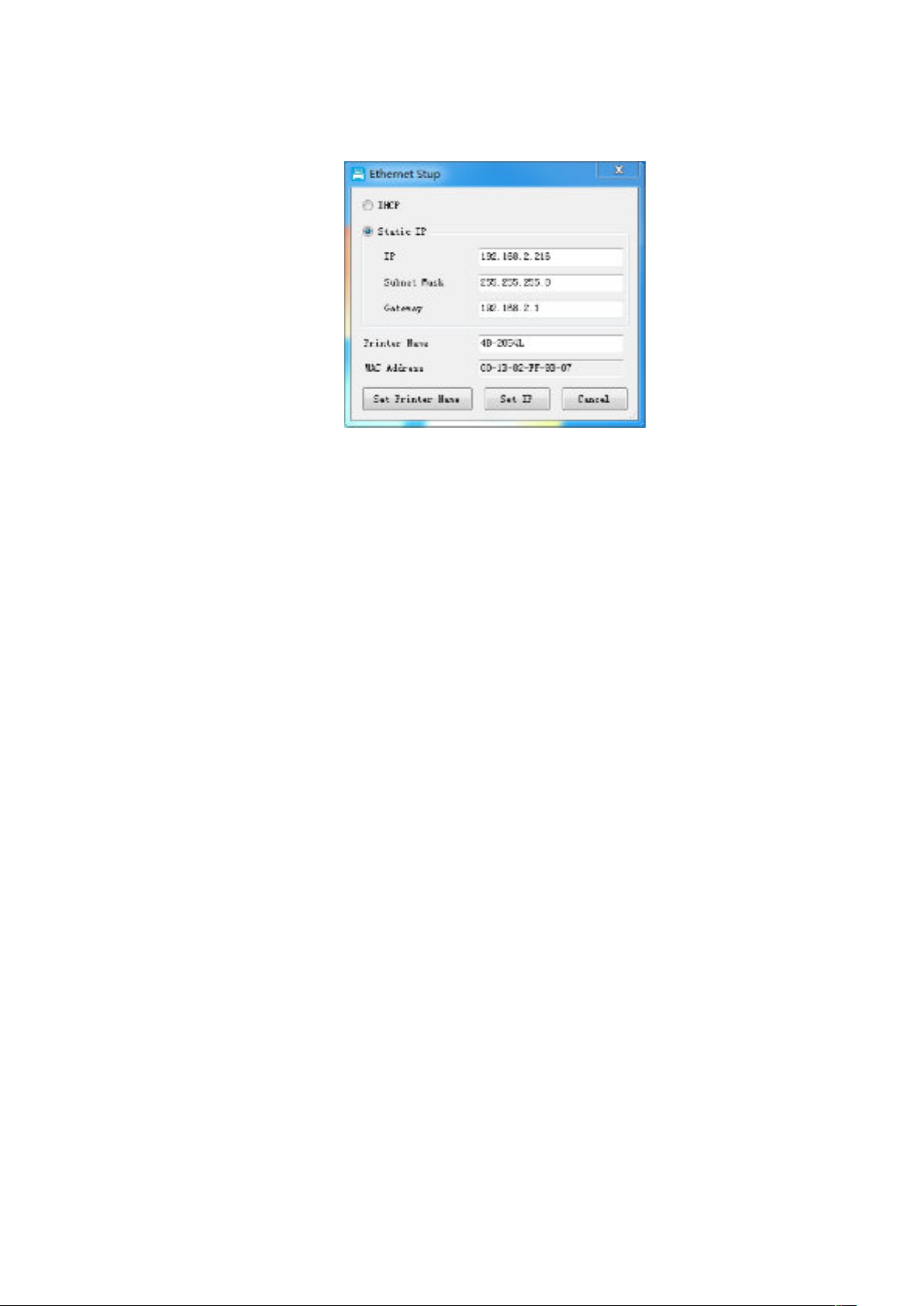
The factory default value set by such IP is “Automatically obtain the IP location”. If you
need to change your IP location, please select “Designate the IP location” and enter the IP,
subnet mask and gateway to be set, and then press the “Set IP” button to set, and the user
can also change the name of the printer by pressing the “Set printer name” button after
entering the intended name in the printer name column.
Note: After pressing the “Set printer name” or “Set IP” button, the printer will reset its
value.
8. Press the “Exit” button to leave this TCP/IP Setup screen and return to the main screen of the
Diagnostic Tool program.
“Factory default value” button
Press this button to change the setting of IP back to the automatic obtaining of IP location
(DHCP) in the factory default setting and reset of the printer name.
“Webpage setting” button
In addition to the setting with the Diagnostic Tool, the user can also set, check or update the
firmware of the printer by opening the webpage via IE or Firefox. By use of this function, the
user may set the printer remotely via the local area network.
20
Page 23

VI. Troubleshooting
6.1 Common problems
The table below shows the common problems the printer operators normally meet and the
solutions to them; if you have tried the troubleshooting in the ways we suggest but the printer is
still not working properly, please contact the customer service of the vendor for more assistance.
- The power indicator is off. * The AC socket plug and the
power supply plug are not
properly connected to the
socket of the printer
* The printer power is not
switched on
- The Diagnostic Tool
displays "Head open"
- The Diagnostic Tool
displays "Paper end"
- The Diagnostic Tool
displays "Paper Jam"
* The cover of printer is not
closed
* The label paper is used up
* The label installation path is
incorrect
* The sensor setting is
incorrect.
* The sensor setting is
incorrect.
* Check the power connector,
and make sure that the AC
socket and the power supply
plug are properly connected
to the printer
* Turn on the power switch
* Close the cover of printer.
* Install new label paper
* Refer to the steps of label
installation and reinstall it
* Calibrate the label.
* Calibrate the volume label
sensor
* The label paper size setting
is incorrect
* There may be volume label
paper stuck inside the printer
mechanism
21
* Set the correct label size
* Clean the inside of the
mechanism
Page 24

Problem
Possible cause
Solution
- Unable to
print
- The memory
space is full
(FLASH/
DRAM)
* The pin of the serial
cable in the
transmission line slot
of the machine is not
of 1 to 1 type
*The FLASH/DRAM
memory space is full
* Reconnect the transmission line
* If you are using a serial port cable,
- Replace the serial port cable. The pin of the
cable must be of 1 to 1 type
- Make sure that the transmission rate of the
printer is set to 9600, n,8,1
* If you are using an Ethernet cable,
- Make sure that the Ethernet RJ-45 blue/purple
light is ON
- Make sure that it is the purple light that blinks
when transmitting data via the Ethernet RJ-45
transmission line
- Make sure that the printer gets an IP address
when it is in the DHCP mode
- Make sure that the IP address setting is correct
when it uses a xed IP address
- Wait a few seconds for the printer to contact the
server and then check the IP address again
* Replace it with a new transmission line
* Clean the print head
* The printing density setting for the printer is
incorrect
* The connection line of the print head is not well
connected. Please turn o the printer and reconnect
the print head cable
* Make sure that the stepper motor cable is
connected correctly
* Make sure that the PRINT program has PRINT
commands at the end of the file, and CRLF is at the
end of each line of the commands
* Clear unnecessary les inside FLASH/DRAM.
* The DRAM can store up to 256 les
* User can store up to 256KB in DRAM
* The FLASH can store up to 256 les
* The maximum a user can store in FLASH is
2560KB
22
Page 25

Problem
Possible cause
Solution
- The microSD
memory card is not
available
- Poor printing
quality
* The microSD memory
card is damaged
* The microSD memory
card is not inserted correctly
* The microSD card is from
unveried manufacturer
* There is dust or adhesive
buildup on the print head
* The printing density is not
set properly
* The print head is damaged
* The print head pressure
setting is inappropriate
* Use a microSD memory card with
supporting capacity
* Re-insert the microSD memory card
* Reinstall the consumables
* Clean the print head
* Clean the rubber roller
* Adjust the printing density and
printing speed of the printer
* Print out the self-test value to check if
the print head is damaged. If yes, replace
it
* Adjust the print head pressure
adjusting knob
- If it is too light on the left of the
printed label, adjust and increase the
value of the pressure adjusting knob on
the left side. If the value is already "5",
but it is still too light, adjust the value of
the pressure adjusting knob back to "1"
and then adjust the Z-axis adjuster to
find the best pressure setting
- If it is too light on the right of the
printed label, adjust and increase the
value of the pressure adjusting knob on
the right side to improve the printing
quality
- Paper skip occurs
while printing
* The label size setting is
incorrect or incomplete
* The label has been
changed without
recalibrating the sensor
* The label sensor is
covered by dust, causing
incorrect detection
23
* If the thickness of the label exceeds
0.22 mm, the printing quality may not be
good enough. Please increase the print
head pressure rst
* Make sure that the print head holder is
fully closed
* Make sure that the label size setting is
correct
* Recalibrate the label sensor
* Remove dust from the sensor with an
air brush
Page 26
Problem
Possible cause
Solution
- The print position is
not correct when
printing small volume
labels
* The label sensor setting is
incorrect
* The label size setting is
incorrect
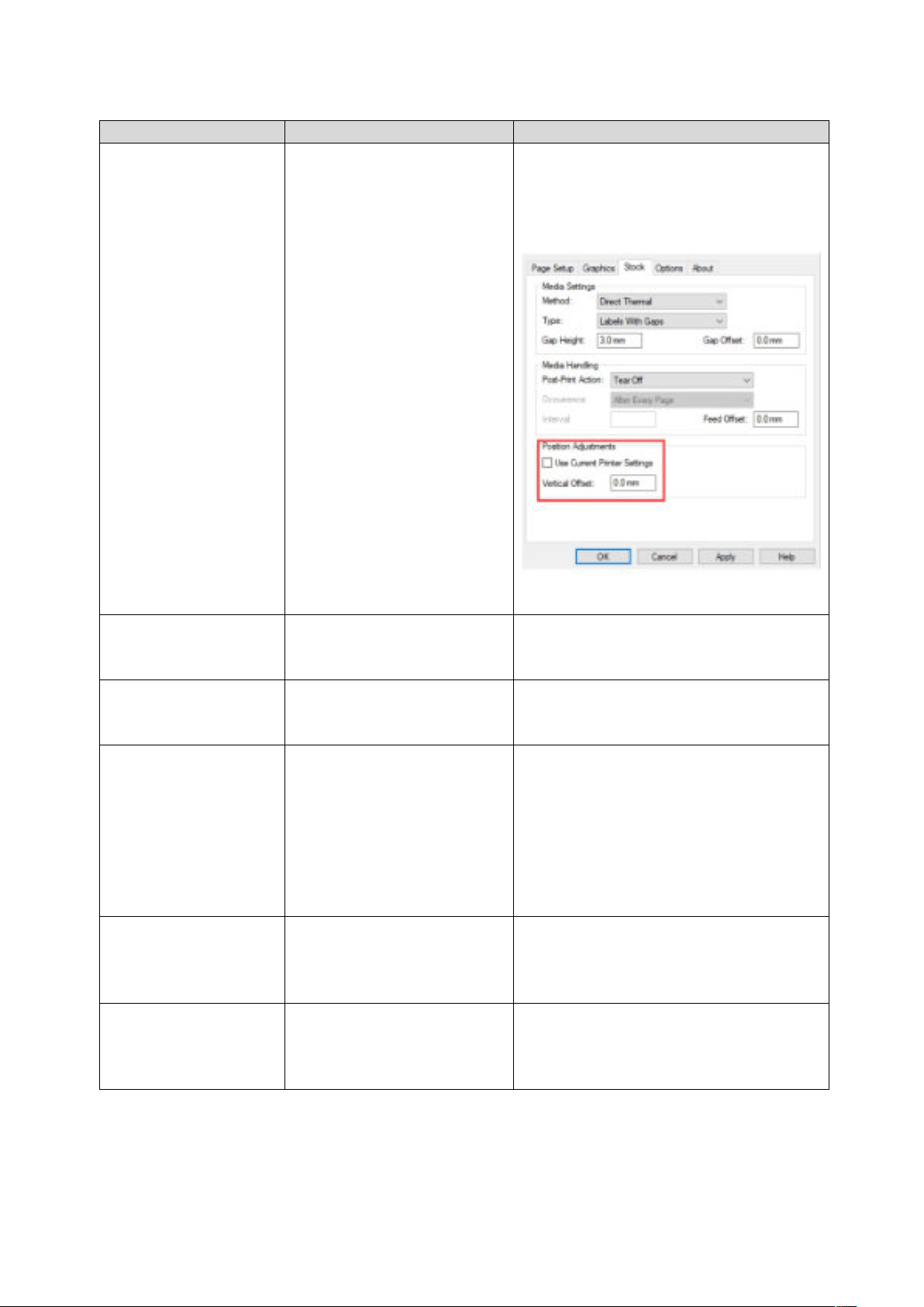
* The vertical oset setting
of the volume label style in
the printer driver is
incorrect
* Recalibrate the label sensor
* Set the correct volume label size and
volume label gap size
* If the BarTender software is used, set
the vertical oset in the printer driver
- Print missing on
both left and right
sides
- The RTC time is
not correct after
restarting the printer
- Wrinkle problem
- Gray lines appear on
black mark paper
- Unstable printing
* The label size setting is
* Set the correct label size
incorrect
* The battery is dead * Check the battery on the main board
* The print head pressure is
uneven
* The label paper is
installed incorrectly
* The printing density is
incorrect
* For uneven print head pressure, refer
to the next section for adjustment
* Set the appropriate label printing
density
* Use the label width adjuster to adapt
it to the label width
* The label paper feeding is
incorrect
* There is dirt on the print
head
* Clean the print head
* Clean the rubber roller
* There is dirt on the rubber
roller
* The printer is in the Hex
Dump mode
* The serial cable (RS-232)
* Turn the printer o and on again to
jump out of the Dump mode
* Reset RS-232
setting is incorrect
24
Page 27
VII. Simple maintenance procedures of the printer
Item
Steps
Recommended frequency
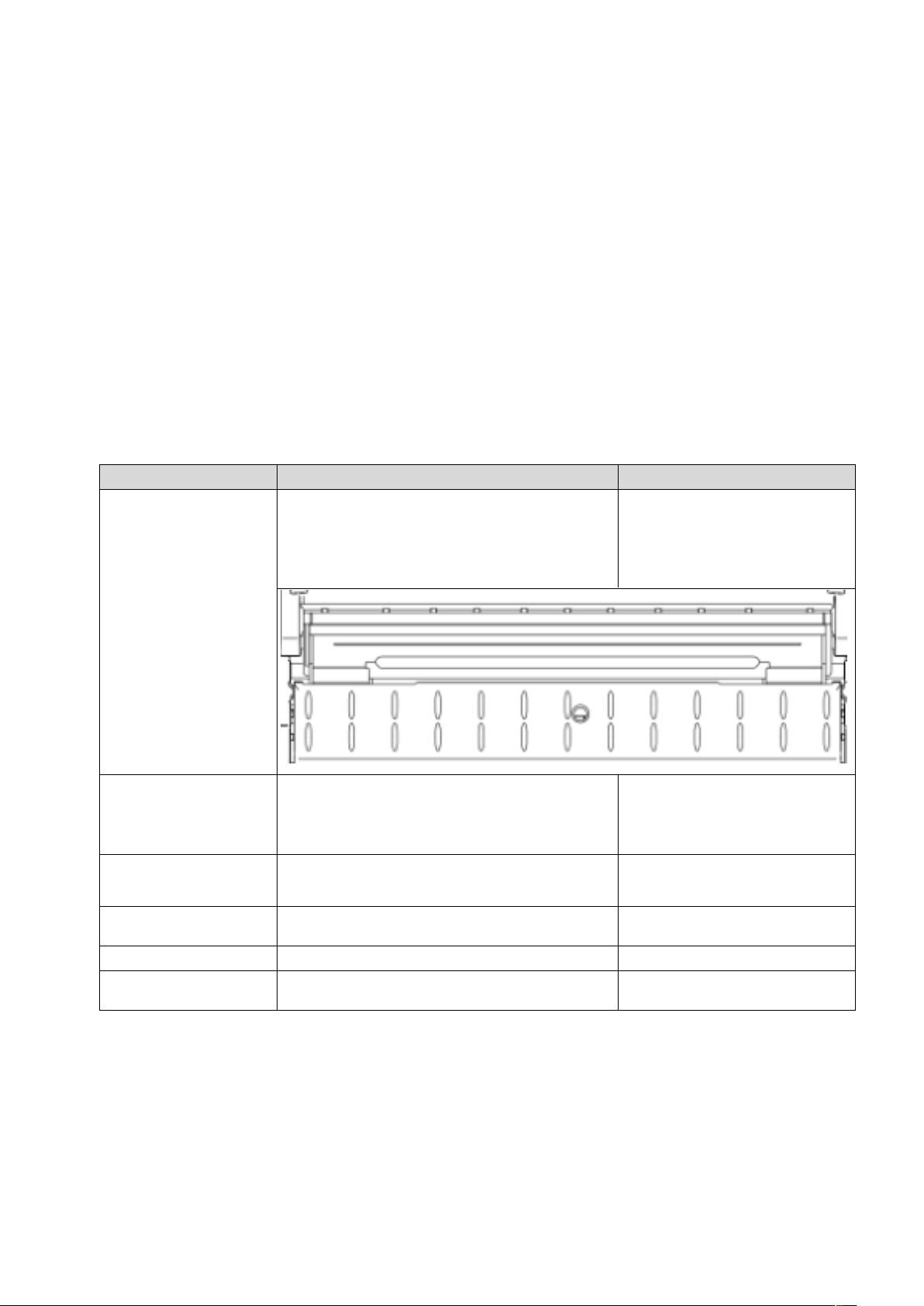
The simple maintenance procedures aim to ensure the printing quality and extend the life of the
printer. Below are some of our recommended maintenance procedures.
1. Clean and maintain your printer by using the tools listed below:
Cotton cloth
Vacuum cleaner or air brush
Medical alcohol
Cotton swab
2. Cleaning steps:
1. Turn o the printer
2. Allow the print head to cool for at least
one minute
3. Wipe the print head surface with a cotton
swab dipped in medical alcohol
Print head
When installing a new roll of
label paper
1. Turn o the printer
Rubber roller
Paper tearing-o piece
Paper stripping piece
Sensor
Outside of the machine Wipe it with a wet cotton cloth
Inside of the machine
2. While rotating the rubber roller, carefully
wipe it with a cotton cloth or cotton swab
dipped in medical alcohol
Wipe it with a cotton cloth dipped in medical
alcohol
Remove dust from the sensor with an air brush
or vacuum cleaner.
Remove dust from inside of the machine with
an air brush or vacuum cleaner
Note:
Do not touch the print head directly by hand. If your hand touches it accidentally, wipe it with
a cotton swab dipped in medical alcohol
Use medical alcohol. Do not use industrial alcohol, which may damage the print head
If your printer displays error messages frequently, clean the sensor of the printer regularly
The equipment can be used safely in tropical climates
When installing a new roll of
label paper
When needed
Monthly
When needed
When needed
25
Page 28

This is a Class A product that may cause radio interference in a living environment. In such
case, user may need to take practical measures accordingly
26
 Loading...