

Page 1

717480312
Owner’s Manual
& Assembly Guide
01C
Model No. STA42-A
4’ x 2’
Nominal Size
R
Base
Size
51” x 27 7/8”
129,5 cm x 70,8 cm
BUILDING DIMENSIONS
Approx.
1,3 m x 0,7 m 0,8 m2 0,7 m
* See Inside for Detailed Safety Information.
†
Size
4’ x 2’ 9 Sq. Ft. 26 Cu. Ft. 54 3/4” 30 1/2” 36” 49 1/2” 26 3/8” 35” 23 5/8” 32 1/2”
Storage
Area
3
Gloves must be worn
at all times to reduce
risk of injury!
†
Size rounded off to the nearest foot
Exterior Dimensions
(Lid Edge to Lid Edge)
Width Depth Height
139,1 cm 77,5 cm 91,4 cm 125,7 cm 67,0 cm 88,9 cm 60,0 cm 82,6 cm
Interior Dimensions
(Wall to Wall)
Width Depth Height
Door
Opening
Width Height
MADE IN USA
Page 2

BEFORE YOU BEGIN...
Safety precautions MUST be followed at all times throughout the construction of your Storette®!
•Care must be taken when handling various pieces of your Storette® since
many contain sharp edges. Please wear work gloves, eye protection and long
sleeves when assembling or performing any maintenance on your Storette®.
•Practice caution with the tools being used in the assembly of your Storette®.
Be especially familiar with the operation of all power tools.
•Keep children and pets away from the worksite during construction. Do not
allow children to help with assembly.
•Do NOT attempt to assemble your Storette® on a windy day. The large panels
can catch the wind like a “sail”, causing them to be whipped around making
construction diffi cult and unsafe.
02C
•If possible, two people should work together to assemble your Storette®. This
will make assembly faster and easier.
•Your Storette® needs to be anchored after assembly. The Storette® may be
anchored to a deck or concrete patio using deck screws or concrete anchors.
You may also anchor it to any fl at, level surface. Alternatively, patio blocks may
be used to anchor the Storette®. See back page for more info.
Reading and following all steps carefully will help make assembly quicker and easier. Before you begin
assembly, be sure to confi rm that all the parts for your building are present using the checklist on pages 3
and 4. If parts are missing, include the model number of your building and contact the retailer where you
purchased your Storette®.
Below is a list of things you will need to assemble your Storette®.
WHAT YOU NEED
• Work Gloves
• Safety Glasses
• No. 2 Phillips Screwdriver (Magnetic Tip Preferred)
• Pliers
RECOMMENDED TIME SAVERS
• Power Drill (Cordless, Variable Speed)
• Nut Driver or Wrench
• Awl (to align holes)
2
Page 3
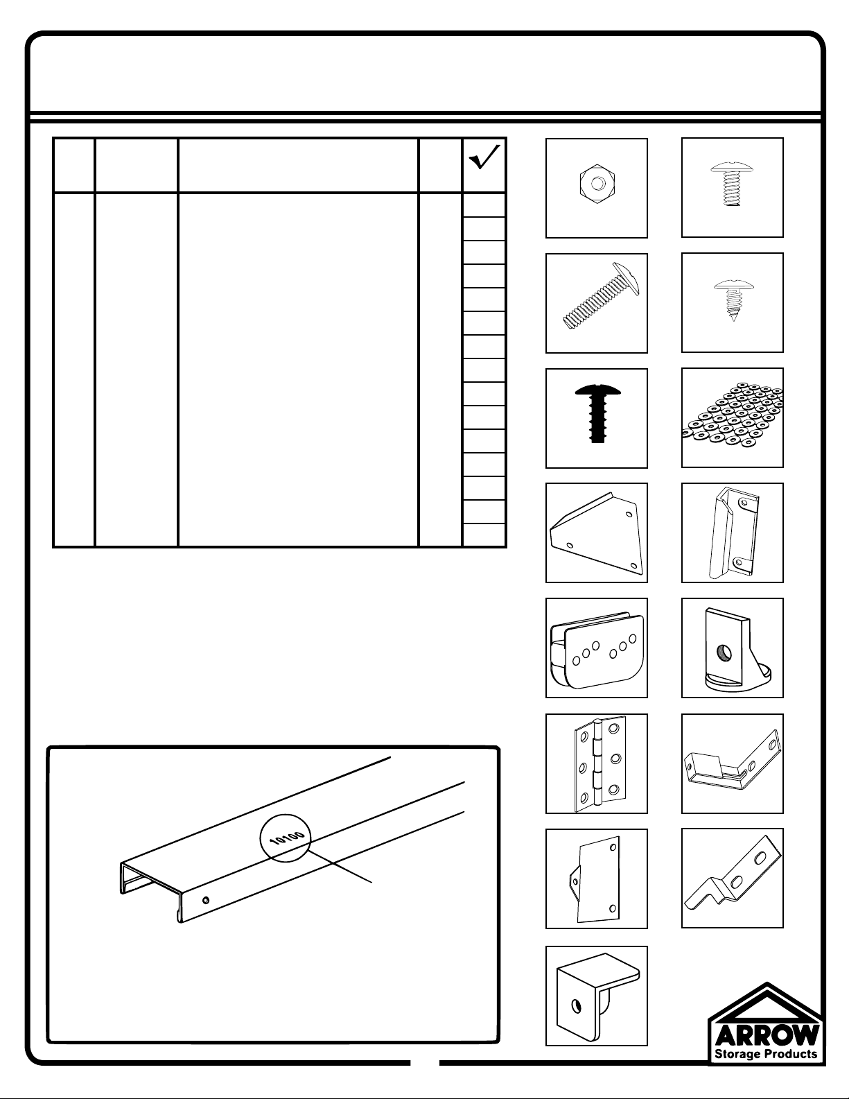
HARDWARE LIST...
03C
Key Part Part Qty.
No. No. Description List
1 65103 Hex Nut (#8-32) 61
2 65923 Bolt (#8-32 x 3/8) (10 mm) 56
3 65958 Long Bolt (#8-32 x 7/8) (22 mm) 2
4 65004 Screw (#8AB x 5/16) (8 mm) 64
5 65900A Black Screw (#10B x 1/2) (13 mm) 8
6 66646 Washer Sheet 2
7 6481 Gusset 2
8 66045 Door Handle 2
9 66769 Door Slide 4
10 66382 Door Guide 4
11 66609 Hinge 3
12 10670 Lid Latch Bracket 1
13 10671 Lid Support Arm Bracket 1
14 10672 Door Latch Finger 1
15 60H Corner Caps 4
1
11/32 Hex.
3
#2 Phillips #2 Phillips
5
#2 Phillips
7
2
#2 Phillips
4
6
8
Confi rm that all hardware and parts are present
before attempting to assemble your Storette®.
For missing parts, include the model number of your
building and contact the retailer where you purchased
your Storette®.
Part Numbers
Part Number
1. Each part has an identifying part number on it.
2. Part Numbers are referenced in each step.
3. Unpainted parts have a stamped in number and painted
parts have a number that is inked on.
9
11
13
15
10
12
14
Remove inked on numbers with soap and water after assembly.
3
Page 4

PARTS LIST...
04C
Key Part Part Qty.
No. No. Description List
1 10653 Door Jamb 2
2 10654 Door Track 1
3 10655 Front Bottom Channel 1
4 10656 Front Corner Panel 2
5 10657 Front Wall Panel 2
6 10658 Horizontal Door Brace 4
7 10659 Lid Diagonal Brace 2
8 10660 Front Lid Channel 1
9 10661 Rear Lid Channel 1
10 10662 Right Lid Channel 1
11 10663 Lower Door Track Angle 1
12 10664 Right Door 1
13 10665 Rear Bottom Angle 1
14 10666 Right Lid Panel 1
15 10667 Rear Top Angle 1
16 10668 Right Top Channel 1
17 10669 Side Bottom Angle 2
18 80039 Left Door 1
19 80041 Left Lid Panel 1
20 80043 Left Top Channel 1
21 80045 Left Lid Channel 1
22 9537 Rear Corner Panel 2
23 9767 Lid Support Arm 1
Selected End Views by Key No.
1
Painted
6
Unpainted
9
Painted
13
Unpainted
17
Unpainted
23
2
Painted
7
Unpainted
10
Painted
15
Unpainted
20
Unpainted
3
Unpainted
8
Painted
11
Unpainted
16
Unpainted
21
Painted
Some Tips for Assembly:
Crimped Rib
Uncrimped Rib
Whenever a crimped rib and an uncrimped
rib meet, the crimped rib should be placed
UNDER the uncrimped rib if possible.
Unpainted
6
4
Page 5
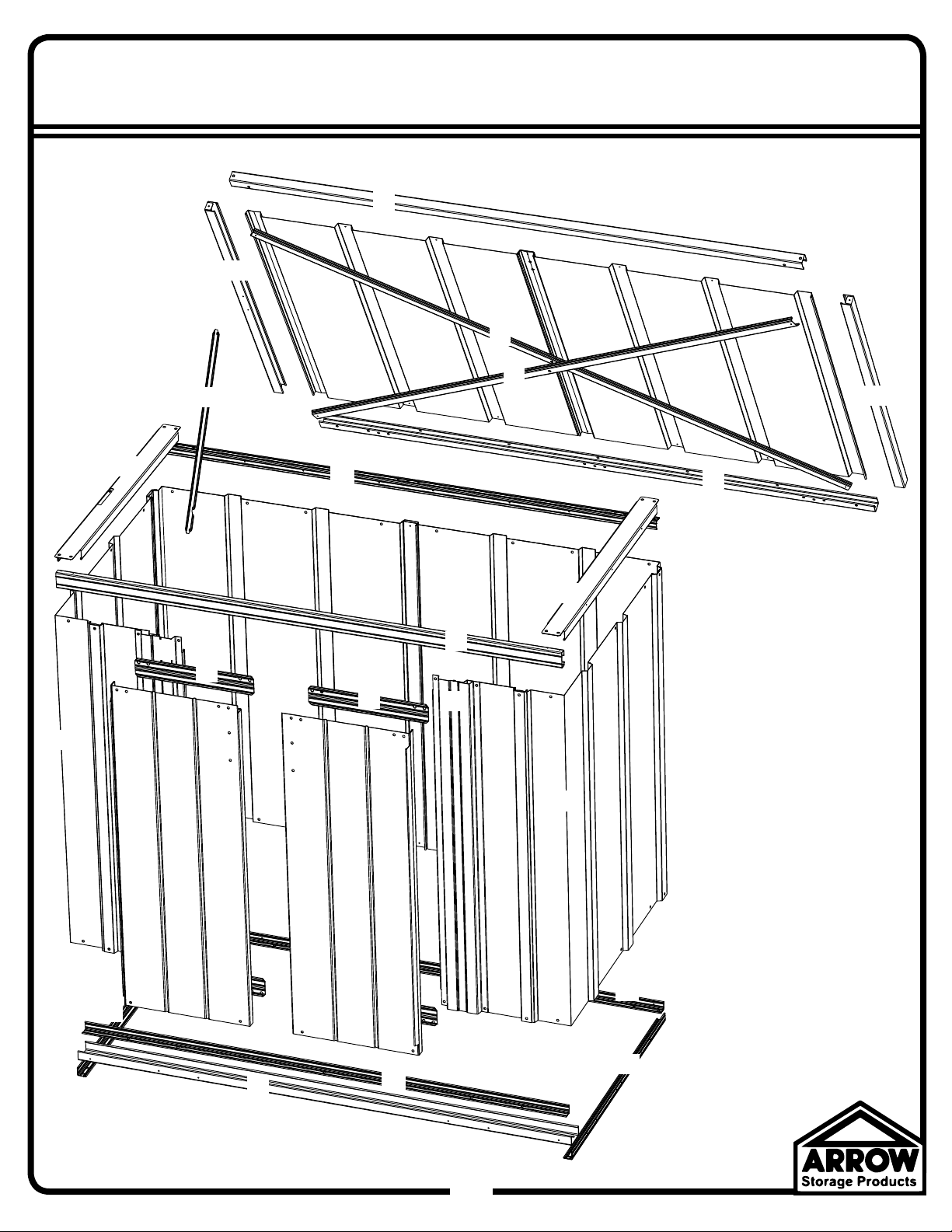
ASSEMBLY BY KEY NO.
8
21
05C
19
23
20
22
5
1
6
4
15
22
6
7
7
9
16
2
1
14
10
17
18
5
12
6
6
3
11
4
13
17
5
Page 6

Step 1
1
2
06C
You will need for this page:
(QTY: 10)
ATTACH IN REAR FIRST FOR EASIER ASSEMBLY.
10656
(QTY: 3)
9537
• 10656 Front Corner Panel (2)
• 9537 Rear Corner Panel (2)
• 10657 Front Wall Panel (2)
• 10655 Front Bottom Channel (1)
• 10663 Lower Door Track Angle (1)
Place Washers on all Bolts and
Screws used on painted parts.
9537
10656
10657
Use Bolts and Nuts to attach the Lower Door Track Angle to the Front Bottom Channel as shown.
ANCHORING HOLES
Double check that the end view of the
assembled frame looks like the image to
the left.
10657
Use Bolts and Nuts to attach the Corners and Front Wall Panels as shown.
This Assembly will be used on the next page.
10663
10655
6
6
Page 7

You will need for this page:
4
5
3
(QTY: 16)
(QTY: 10)
07C
• Front Bottom Channel Assembly from previous page
• 10665 Rear Bottom Angle (1)
• 10669 Side Bottom Angle (2)
• 6481 Gusset (2)
10665
For ease of assembly, the bottom of the
Storette® will be assembled fi rst, and
the Storette® will then be turned over to
complete assembly (see Step 1.5 below).
Next, position the Side Bottom
Angles as shown and secure
them to the walls with Screws.
Position the Gussets in rear
and secure the Side Bottom
Angles to the Front and
Rear Frames using Bolts
and Nuts as shown.
6481
10669
Use Screws to attach the Front Bottom
Channel Assembly and Rear Bottom
Angle to the Walls as shown.
Side Angle over Rear Angle.
6481
10669
After you have completed these steps,
carefully turn the Storette® over as shown.
7
Page 8

Step 2
4
3
1
2
08C
You will need for this page:
(QTY: 18)
10661
Slide ALL Door Slides into the Door Track before installation.
(QTY: 18)
10667
• 10667 Rear Top Angle (1)
• 10661 Rear Lid Channel (1)
• 66609 Hinge (3)
• 10654 Door Track (1)
• 66769 Door Slide (4)
• 10653 Door Jamb (2)
Attach the Rear Top Angle, Hinges, and Rear
Lid Channel together using Bolts and Nuts as
shown. Double check that the end view of the
assembled piece matches the image above.
Long leg on top.
10654
10653
10654
10653
Attach the Rear Top Angle Assembly and Door
Track to the Walls with Screws as shown.
Next, attach the Door Jambs to the Walls and
Door Track as shown.
TO REAR
Wall Panel
6
8
Page 9

You will need for this page:
5
6
7
8
(QTY: 16)
Position the Left and Right Top Channels as shown and secure to Walls with Screws.
(QTY: 4)
• 10668 Right Top Channel (1)
• 80043 Left Top Channel (1)
• 10666 Right Lid Panel (1)
• 80041 Left Lid Panel (1)
(QTY: 4)
Next, secure the Left and Right Top Channels to the Front and Rear of the
80043
• 10660 Front Lid Channel (1)
building with Screws in Front and Bolts and Nuts in Rear as shown.
10668
09C
10660
Notched side of Frame faces INSIDE building.
80041
10666
Slide Left and Right Lid Panels into
the Rear Lid Channel and secure with
Screws as shown. Do not fully tighten.
Next, position the Front Lid Channel
and secure with Screws as shown. Do
not fully tighten at this time.
9
Page 10

Step 3
1
2
3
You will need for this page:
(QTY: 2)
Working with one Brace at a time, attach
each Diagonal Brace to the bottom of the
Lid at the ends and then rotate to align with the
top of the Lid.
the Braces in the middle with a Long Bolt and
Nut as shown. Fully tighten all Screws and Bolts,
including Screws from previous step.
(QTY: 4)
With both Braces in place, secure
(QTY: 1)
10C
• 10659 Lid Diagonal Brace (2)
• 10671 Lid Support Arm Bracket (1)
• 80045 Left Lid Channel (1)
10659
10659
When inserting the Long
Bolt in the Diagonal Braces,
fi rst locate the Nut against the back side
of the hole with your fi nger and thread
the Bolt into the Nut. This will make the
process easier.
Attach the Lid Support Arm Bracket to the Left Lid Channel with Screws as shown.
10671
80045
The end view of the assembled
Channel should match the image
to the left.
Bend the tabs on both ends
of the Left and Right Lid
Channels as shown.
6
10
Page 11

You will need for this page:
4
5
• 10662 Right Lid Channel (1)
• 80045 Left Lid Channel (1)
• 60H Corner Cap (4)
(QTY: 4)
Slide Left and Right Lid Channels into place as shown below. DO NOT
secure Lid Channels until Corner Caps are in place (see below).
80045
11C
10662
10662
60H
Position the Corner Caps and secure with Screws as shown.
60H
10662
60H
60H
11
Page 12

Step 4
3
1
2
You will need for this page:
(QTY: 1) (QTY: 1)
Place a Bolt thru the bottom of the Lid Support Arm as
shown. There should be a Nut on BOTH sides of the
Support Arm as indicated.
12C
• 9767 Lid Support Arm (1)
Next, place a Long Bolt thru the
Lid Support Arm Bracket and
secure with a Nut as shown.
9767
Now slide the Support Arm up thru the slot in the Left Top Channel as shown.
Notch in Lid Support Arm MUST face rear of Storette®.
6
12
Page 13

You will need for this page:
4
5
(QTY: 2)
Rotate the Support Arm into place and
slide it onto the Long Bolt as shown.
13C
Next, put two Nuts on the end of the Bolt one at a
time. Tighten the second Nut against the fi rst. The
second Nut will act as a ‘Jam Nut’, keeping the fi rst
Nut in place.
Be sure to leave a gap as indicated in the image to the
right. This gap will allow the Support Arm to ‘fl oat’ as
the Lid is closed. If you do not leave a gap, the Lid may
close improperly.
13
Page 14

Step 5
1
2
14C
You will need for this page:
(QTY: 4)
80039
(QTY: 4)
Do NOT place hardware thru the top row of holes
yet. These lines are to show alignment only.
(QTY: 8)
• 10664 Right Door (1)
• 80039 Left Door (1)
• 10658 Horizontal Door Brace (4)
• 10672 Door Latch Finger (1)
• 66045 Door Handle (2)
• 66382 Door Guide (4)
10658
66045
80039
Horizontal Door Brace MUST
be attached on INSIDE of Door
as shown below.
10672
66045
10658
10664
10664
10664
INSIDE VIEW OF Storette®
80039
6
14
66382
10658
Attach the Door Handles to the Left and Right
Doors with Bolts and Nuts as shown. Attach the
Door Guides and the Horizontal Door Braces to
the BOTTOM side of the Left and Right Doors using
Bolts and Nuts as shown.
Next, place one Door in the Front Bottom Frame
and rotate it into place as shown. Position the
Horizontal Door Brace (and Door Latch Finger
for the Left Door) as shown and secure to Door
Slides with Black Screws.
Repeat for other Door.
Each Door Slide has three sets of holes. Install Doors
by placing the Black Screws thru the middle holes
fi rst. If Doors do not align, raise or lower the Doors by
moving the Screws to a different set of holes.
66382
Middle Holes
66382
10658
66382
Page 15

You will need for this page:
3
• 10670 Lid Latch Bracket (1)
(QTY: 2)
15C
Position the Lid Latch Bracket and secure with
Bolts and Nuts as shown.
10670
DOOR OPEN
The Latch and Latch Finger should interlock
as shown when the Left Door is closed. If
they do not align, loosen the Bolts securing
them and slide to align.
With the Lid Latch in place, CLOSING the Doors will LATCH
the Lid and OPENING the Doors will UNLATCH the Lid.
DOOR CLOSED
LID UNLATCHED
LID LATCHED
15
Page 16

Exterior Care:
For a long lasting fi nish clean and wax the exterior surface. We recommend washing with a mild soap solution. DO
NOT use power washing to clean your Storette®. Using a spray automotive type wax periodically on the exterior is
highly recommended if you are in a high humidity or coastal climate region.
Combustibles and corrosives must be stored in air tight containers designed for chemical and/or combustible
storage. Corrosive chemicals such as fertilizers, pesticides and herbicides should be cleaned off the interior and
exterior surfaces immediately. Rust caused by chemical damage is not covered by the warranty.
DO NOT STORE POOL CHEMICALS IN YOUR Storette® - THIS VOIDS YOUR WARRANTY
Rust protection precautions may help to stop rust from developing, or stop it quickly as soon as it appears.
• Avoid nicking or scraping the coating surface, inside and out.
• Use washers everywhere indicated in this manual to help prevent corrosion.
• Keep lid, base perimeter and door tracks free of debris and leaves which may accumulate and retain moisture.
These can do double damage since they give off acid as they decay. Lubricate door track as needed.
• Touch up scrapes or nicks and any area of visible rust as soon as possible. Make sure the surface is free of
moisture, oils, dirt or grime and then apply an even fi lm of high quality touch-up paint.
16C
• Various paint manufacturers provide products for rust treatment and coverage. If surface rust does appear on
your Storette® we recommend treating those areas as soon as possible, following the paint supplier of your choice
instructions.
Please note, Manufacturer cannot be held responsible for any consequences due to buildings that are not installed
per these instructions, or for damage due to weather conditions or acts of God.
Anchoring Your Storette®
The entire fl oor frame MUST be securely anchored once the building is erected.
Here are recommended ways of anchoring.
Anchoring into Concrete:
Anchoring into Wood/Post:
Use 1/4" (6 mm) Wood Screws. There are 1/4" (6 mm)
dia. holes provided in the frames for proper anchoring.
1. For poured concrete slab or footing or patio blocks:
Use 1/4" x 2" (6 mm x 51 mm) Lag Screws.
2. For Anchor Post of Concrete poured after building is
erected: Use 1/4" x 6" (6 mm x 152 mm) Lag Screws.
1. 2.
1.
Keep these assembly instructions and owner’s manual for future reference.
2.
 Loading...