

Page 1

Owner’s Manual
Refrigerated
Compressed Air Dryers
Model F-20
Read carefully before attempting to assemble, install, operate or maintain the
product described. Protect yourself and others by observing all safety information.
Failure to comply with instructions could result in personal injury and/or property
damage. Retain instructions for future reference.
WARNING: Air treated by this equipment is not suitable for breathing without
further purifi cation. Refer to O.S.H.A. standards for the requirements for breathing
quality air.
Figure 1 - F-20
ARROW DRYERS 745 CLARK AVE. BRISTOL, CT 06010 TOLL FREE: (877) 640-8300
Form F-0031A
Revised 10/04
Page 2
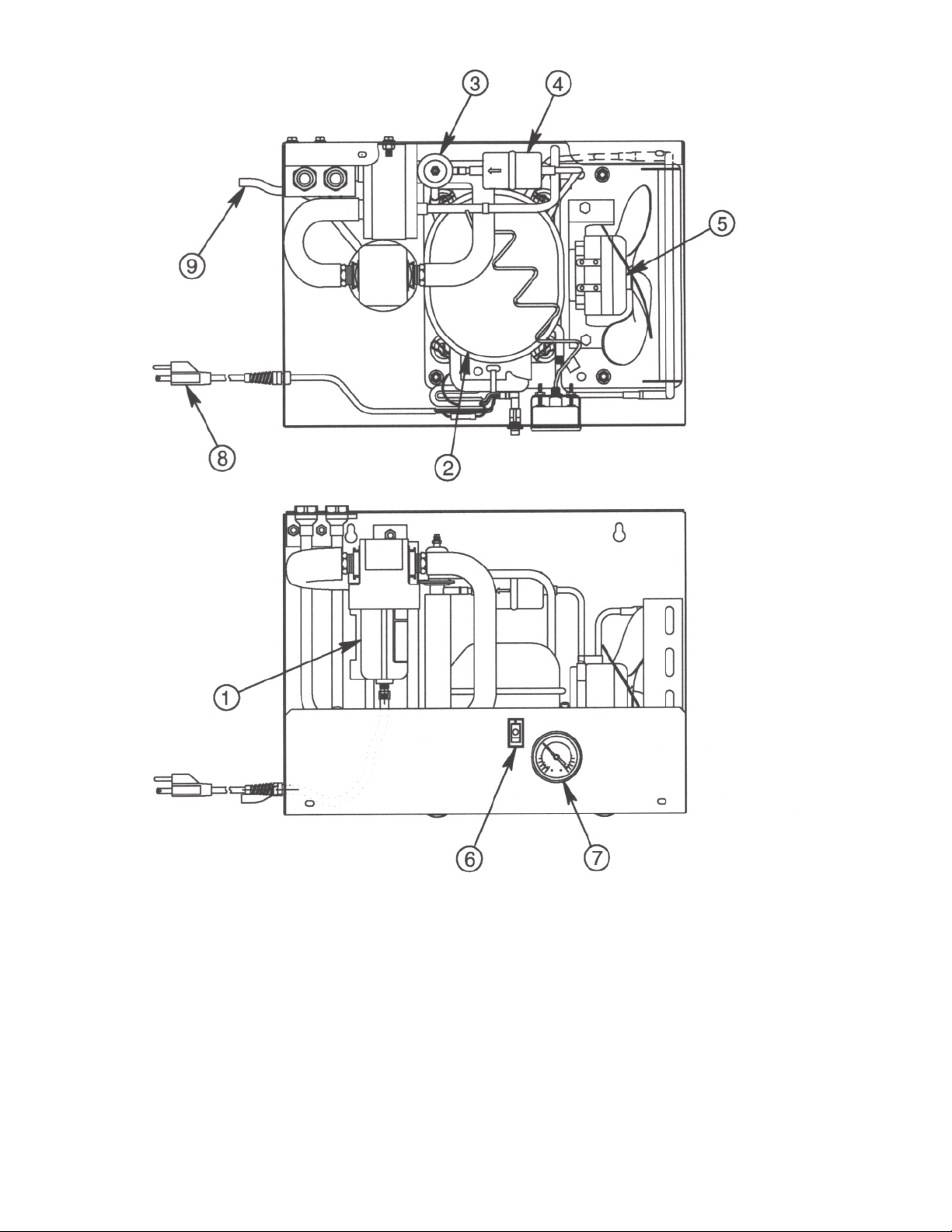
1) Separator
2) Compressor
3) Expansion/Control Valve
4) Refrigerant Filter
5) Fan Motor
6) Power On Light/Switch
7) Dew Point Indicator
8) Power Cord
9) Drain Line
1
Page 3
Receiving and inspection
Arrow Dryers are carefully prepared for shipment at the
factory to protect them from damage in transit. Dryers
are shipped F.O.B. factory. Immediately upon arrival,
check the dryer for possible damage. If
damage is found, report it to the carrier and file
a damage claim.
Check the suction pressure gauge. If the suction pressure
gauge reads zero, it indicates a possible refrigerant leak.
Notify your dealer immediately.
Be sure you have the right dryer. Check the nameplate for
voltage and amperage
Location and Installation
Locate the dryer indoors in a protected area where ambient temperature will range between 45ºF and 100ºF. Dryers
are usually located near the compressor. Do not cycle the
dryer with the compressor. If an aftercooler is used after the
compressor, install the dryer downstream of the aftercooler
and receiver (see figure 2). Install the dryer so that there is
sufficient room around it to permit circulation of air through
the refrigeration condensing unit. Allow for easy access into
the dryer through the cover panel.
Check the nameplate for voltage and amperage. The dryer
is furnished with a 6 foot electrical cord for connection to a
grounded outlet.
How the Air Dryer Works
Compressed air enters the inlet and passes through the
air-to-air heat exchanger where the air is partially cooled
by the exiting cold air. Next, the air passes through a refrigerant-to-air heat exchanger where it is cooled to near
the freezing point of water. As the air is cooled, it loses the
capacity to hold water vapor. The water vapor condenses
into water droplets and drains to the separator. Passing
through the separator, air flow slows down and causes
more water to condense and collect in the bottom of the
separator bowl. The water is exhausted by the float drain
(see figure 4).
The compressed air, now at a pressure dew point of 35ºF,
leaves the dryer through the air-to-air heat exchanger
where it is heated by the incoming air.
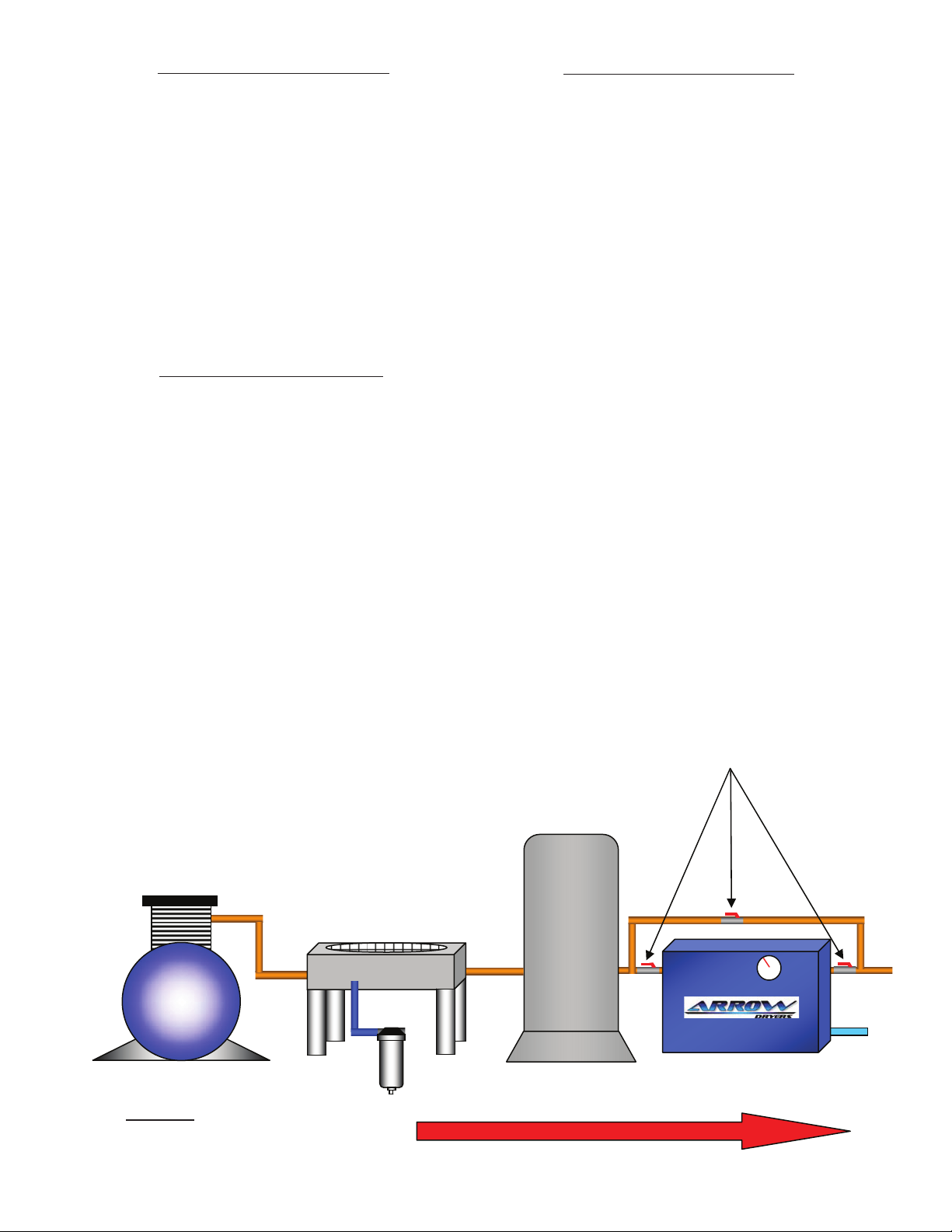
Typical Compressed Air Systems
The dryer can be mounted on a wall with the key hole slots
provided or on a floor stand.
Be sure that the compressor air passes through the dryer
in the proper direction. Connect the compressed air lines to
the inlet and outlet connection as marked on the cabinet.
Connect the air lines with standard pipe fittings.
The mechanical separator has an automatic float drain with
a ⅜” plastic drain line connection that exits through the
dryer cabinet.
It is recommended that a bypass line is piped around the
dryer. Shutoff valves should be installed at both inlet and
outlet, with another valve in the bypass line. This complies
with O.S.H.A. lockout regulations and permits the dryer to
be removed from the system or serviced without turning off
the air supply.
3 Valve Dryer By-Pass
Air Receiver
Compressor
Figure 2
Aftercooler
Air Flow
Separator w/ Auto Drain
2
Air Dryer
Condensate
Drain
Page 4

Dimensions
F-20 Air Dryer
F-20 Wiring Diagram
115/220V CSIR
Specifi cations
Model Power Capacity Dimensions Air Line Drain Net Max. Full L.R.
No. Supply SCFM (Inches) Conn. Line H.P. Refrig Wt. Press. Load AMP
@ 100 PSIG Length Height Width FPT Conn. Charge* Lbs. PSI AMP
O.D.
F-20-1 115/1/60 20 18 14.0 13 1/2” 3/8” 1/6 10 OZ. 50 250 3.3 18
F-20-2 230/1/60 20 18 14.0 13 1/2” 3/8” 1/6 10 OZ. 50 250 1.6 9.3
F20-250 220/1/50 20 18 14.0 13 1/2” 3/8” 1/6 10 OZ. 50 250 1.7 10.5
*Refrigerant R-134A
3
Page 5

Design Conditions
The Dryer must not be cycled with the air compressor. The dryer is non-cycling and is designed to run
continuously (even under light loads). If the compressed
air system remains pressurized and the air compressor cycles off and on to maintain line pressure, the dryer should
remain in operation to keep the air lines dry.
Air Flow SCFM: The rated air flow (SCFM) of the dryer
is designed for 100 PSIG. Above the rated air flow, the dew
point will rise and moist air may reappear downstream. The
dryer may cycle off and on under excessive load and cause
compressor damage.
Inlet Air Temperature: The dryer will function normally
up to 100ºF. Above this temperature, the dryer capacity will
fall off. Inlet air temperature should be controlled so that it
does not exceed 100ºF.
Line Pressure: The maximum design pressure is 250
PSIG. The standard internal float drain in the separator will
not rise and water will ejected.
How to Make Minor Refrigerant
Suction Pressure Adjustments
1) Keep the dryer running under no load and turn off or
bypass the compressed air.
2) Remove the dryer cover and locate the control valve
(See Figure 3).
3) Loosen the locknut and turn clockwise to increase or
counterclockwise to decrease the suction pressure (1/4
turn will normally be enough). Tighten lockout securely
and wait 3 to 4 minutes for the suction pressure to
settle. Repeat if needed.
Figure 3
Maintenance and Care
Periodically or as part of a preventative maintenance program, check the following:
Ambient Air Temperature: Locate the dryer indoors in
a protected area where the ambient temperature will range
between 45ºF and 100ºF. Note: Above an ambient temperature of 100ºF the refrigerant will rise until the dryer shuts
down. Several off and on cycles under these conditions will
damage the compressor.
Automatic Expansion Valve: The automatic expansion valve regulates the refrigerant suction pressure. The
expansion valve is factory set between 33 and 36 PSIG.
Always turn the dryer on 5 to 10 minutes before
the air compressor. This will allow the dryer to reach
operating temperature and will prevent moist air downstream of the dryer. After starting the dryer, the dew point
indicator will slowly drop and hold be within the green area
of the gauge.
A lighted on/off switch glows when the power is on. During normal operation, the light will be on and the gauge
will read in the green area. If the gauge reads in lower
red area, the cause is a low refrigerant charge or low expansion valve setting. If the gauge reads in the higher red
area, the compressor could be off. Other causes of a high
gauge reading: a dirty air cooled condenser, high ambient air temperature, high inlet air temperature or an air
flow above the dryer’s capacity. When the dryer is off, the
gauge should read close to room temperature.
Start UP
Be sure that there is a free flow of water from the separator
drain. Check the drain mechanism and bronze element periodically and clean monthly. The drain cock can be opened
manually under pressure by turning the knurled stem.
To clean the drain assembly, bypass the air supply. Remove the bowl and then remove the float assembly and
wash all part in warm soapy water. Clean bronze element
with kerosene. Reassemble in the reverse order.
Be sure that there is a free flow of air over the condenser
coils. Check the condenser fins periodically to prevent a
build up of dust deposit. If fins are coated with dust, blow
compressed air through the fins to clean.
Frosting on refrigerant lines is an indication of too much refrigeration capacity. This results in frozen air passages and
prevents air flow through the dryer. It may be necessary to
increase the refrigerant suction pressure.
Dry Air Exits
Wet Air Enters
Model F-20
Bronze Element
Figure 4
Float Drain
4
Quite Zone to
Eliminate Carryover
Page 6

TROUBLESHOOTING CHART
Symptom Possible Causes(s) Corrective Action
Unit will not run. 1. No Power. 1. Correct power supply, fuses,
circuit breaker.
2. Internal compressor overload. 2. Feel the temperature of the comp-
ressor and allow to cool off if hot.
Observe the fan motor. Have the
motor checked if it does not run.
Clean the condenser.
Dew Point Indicator Red (High) 1. Internal compressor overload. 1. Check for air overload. Check inlet
air temperature. Check operation
of fan motor.
2. High ambient temperature. 2. Check room temperature and hold
between 45°F and 100°F.
Dew Point Indicator Red (Low) 1. High air fl ow. 1. Air fl ow above rated fl ow of dryer.
2. Drain valve not discharging. 2. Manually blow down drain until
water fl ow stops. Clean drain.
3. Freezing moisture in evaporator. 3. Re-adjust hot gas valve to the green
area on the dew point indicator gauge.
(See minor pressure adjustment)
Water downstream of dryer 1. Compressed air is fl owing through 1. Dryer must be operating 5-10
dryer before it is turned on. minutes before compressed air load.
2. Dirty separator element or drain. 2. Disassemble and clean.
3. Overload dryer above air fl ow 3. Reduce air load to dryer
capacity. specifi cations.*
4. High suction pressure. 4. Inlet air temperature too hot.
5. Low outlet air pressure. 5. Freezing of water, adjust suction
pressure.*
6. Low refrigerant charge. 6. Contact service technician to leak
check.
*ALL ADJUSTMENTS MUST BE MADE WITH DRYER RUNNING UNDER NO COMPRESSED AIR LOAD.
5
Page 7

If Trouble Starts
If the dryer cycles off and on for any reason TURN OFF
THE DRYER. Call the factory for instructions, Check or
repairs of the refrigeration systems must be made by
a qualified refrigeration service technician. Before call-
ing the factory for instructions, have the following data to
report.
Model No.
Serial No.
Refrigeration Suction Pressure.
REPLACEMENT PARTS
Model F-20-1 F20-2 F20-250
Voltage 115/1/60 230-220/1/60 240-220/1/50
Compressor Make TECUMSEH R-134A TECUMSEH R-134A TECUMSEH R-134A
Separator/
Drain Assembly PART NUMBER PART NUMBER PART NUMBER
Separator F354F-S2 F354F-S2 F354F-S2
Bowl Separator 75180-S2 75180-S2 75180-S2
Repair Kit RKF35 RKF35 RKF35
Element Kit EK35 EK35 EK35
Float Drain FD06B FD06B FD06B
Refrigeration
System
Condensing Unit 97829 97799 97834
Compressor 97836 97838 97837
Condenser 92950 92950 92950
Expansion Valve 91221 91221 91221
Refrigerant Filter 91235 91235 91235
Heat Exchanger 14100 14100 14100
Electrical
Fan Motor 94930 92933 92933
Fan Blade 92940 92940 92940
Overload 91411 91409 91409
Power On Light/Switch 57300 57300 57300
Gauges
Dew Point Temp. Indicator 14765 14765 14765
Cabinet Panels
Base 14011 14011 14011
Cover 14016 14016 14016
Right Side Vented 92430 92430 92430
Left Side Vented 14121 14121 14121
6
Page 8

ORDER REPLACEMENT PARTS
BY CALLING
(877) 640-8300
Please provide following information:
• Model Number
• Serial Number (if any)
• Part Description and Number
Address parts correspondence to:
ARROW DRYERS
745 Clark Ave.
Bristol, CT 06010
WARRANTY POLICY
When used under the conditions recommended by the manufacturer, Arrow Dryers, this
model is warranted to be free from defects in material and workmanship for a period of
twenty-four (24) months from date of receipt, not to exceed thirty (30) months from the
factory ship date, provided Arrow is furnished the customer’s name, address, and date of
shipment information
These units will utilize either a braze plate or modular type heat exchanger which will be
warranted for five (5) years. This warranty is limited to the replacement of the heat exchangers, F.O.B. Factory, and subject to the same restrictions as outlined below concerning misuse, abuse or accident. The automatic drain carries a 90-day warranty.
This warranty will apply to equipment installed, operated and maintained in accordance
with the procedures and recommendations as outlined in the owner’s manual published
by Arrow Dryers.
During the life of this warranty, Arrow Dryers will repair or replace (at Arrow Dryers’ option) any defective part or assembly, free of charge, F.O.B. its plant if such defect occurred
in normal service and was not due to apparent misuse, abuse or accident.
Any warranty service performed in the field must be authorized by Arrow Dryers, Unauthorized service voids the warranty and any resulting charge will not be paid by Arrow
Dryers.
Arrow Dryers makes no other warranties or guarantees, expressed or implied. The merchantability of the components is expressly excluded. The manufacturer assumes no liability for indirect or consequential damages.
7
 Loading...